EP2566086A2 - Method and apparatus for transmitting and receiving information in a broadcasting/communication system - Google Patents
Method and apparatus for transmitting and receiving information in a broadcasting/communication system Download PDFInfo
- Publication number
- EP2566086A2 EP2566086A2 EP12181864A EP12181864A EP2566086A2 EP 2566086 A2 EP2566086 A2 EP 2566086A2 EP 12181864 A EP12181864 A EP 12181864A EP 12181864 A EP12181864 A EP 12181864A EP 2566086 A2 EP2566086 A2 EP 2566086A2
- Authority
- EP
- European Patent Office
- Prior art keywords
- bits
- parity
- punctured
- indicates
- bch
- Prior art date
- Legal status (The legal status is an assumption and is not a legal conclusion. Google has not performed a legal analysis and makes no representation as to the accuracy of the status listed.)
- Granted
Links
- 238000000034 method Methods 0.000 title claims abstract description 39
- 238000004891 communication Methods 0.000 title claims abstract description 22
- 230000005540 biological transmission Effects 0.000 claims description 47
- 101100340610 Mus musculus Igdcc3 gene Proteins 0.000 claims description 24
- 230000010363 phase shift Effects 0.000 claims description 3
- 230000011664 signaling Effects 0.000 description 33
- 238000004904 shortening Methods 0.000 description 29
- 230000008859 change Effects 0.000 description 8
- 238000010586 diagram Methods 0.000 description 8
- 238000012545 processing Methods 0.000 description 6
- 238000012937 correction Methods 0.000 description 3
- 230000015556 catabolic process Effects 0.000 description 2
- 238000006731 degradation reaction Methods 0.000 description 2
- 238000005562 fading Methods 0.000 description 2
- 230000008569 process Effects 0.000 description 2
- 230000007423 decrease Effects 0.000 description 1
- 238000012217 deletion Methods 0.000 description 1
- 230000037430 deletion Effects 0.000 description 1
- 238000011161 development Methods 0.000 description 1
- 230000000694 effects Effects 0.000 description 1
- 230000006872 improvement Effects 0.000 description 1
- 239000011159 matrix material Substances 0.000 description 1
- 238000011160 research Methods 0.000 description 1
Images


Classifications
-
- H—ELECTRICITY
- H04—ELECTRIC COMMUNICATION TECHNIQUE
- H04L—TRANSMISSION OF DIGITAL INFORMATION, e.g. TELEGRAPHIC COMMUNICATION
- H04L1/00—Arrangements for detecting or preventing errors in the information received
- H04L1/004—Arrangements for detecting or preventing errors in the information received by using forward error control
- H04L1/0056—Systems characterized by the type of code used
- H04L1/0067—Rate matching
- H04L1/0068—Rate matching by puncturing
-
- H—ELECTRICITY
- H04—ELECTRIC COMMUNICATION TECHNIQUE
- H04L—TRANSMISSION OF DIGITAL INFORMATION, e.g. TELEGRAPHIC COMMUNICATION
- H04L1/00—Arrangements for detecting or preventing errors in the information received
- H04L1/004—Arrangements for detecting or preventing errors in the information received by using forward error control
- H04L1/0056—Systems characterized by the type of code used
- H04L1/0057—Block codes
-
- H—ELECTRICITY
- H04—ELECTRIC COMMUNICATION TECHNIQUE
- H04L—TRANSMISSION OF DIGITAL INFORMATION, e.g. TELEGRAPHIC COMMUNICATION
- H04L1/00—Arrangements for detecting or preventing errors in the information received
- H04L1/004—Arrangements for detecting or preventing errors in the information received by using forward error control
- H04L1/0072—Error control for data other than payload data, e.g. control data
-
- H—ELECTRICITY
- H04—ELECTRIC COMMUNICATION TECHNIQUE
- H04L—TRANSMISSION OF DIGITAL INFORMATION, e.g. TELEGRAPHIC COMMUNICATION
- H04L1/00—Arrangements for detecting or preventing errors in the information received
- H04L1/004—Arrangements for detecting or preventing errors in the information received by using forward error control
- H04L1/0056—Systems characterized by the type of code used
- H04L1/0064—Concatenated codes
- H04L1/0065—Serial concatenated codes
-
- H—ELECTRICITY
- H04—ELECTRIC COMMUNICATION TECHNIQUE
- H04L—TRANSMISSION OF DIGITAL INFORMATION, e.g. TELEGRAPHIC COMMUNICATION
- H04L1/00—Arrangements for detecting or preventing errors in the information received
- H04L2001/0092—Error control systems characterised by the topology of the transmission link
- H04L2001/0093—Point-to-multipoint
Definitions
- the present invention relates generally to transmission and reception of information in a broadcasting/communication system, and more particularly, to a method and apparatus for controlling a code rate according to transmission and reception of signaling information in a broadcasting/communication system.
- a broadcasting/communication system may experience poor link performance due to noise, a fading phenomenon, and Inter-Symbol Interference (ISI).
- ISI Inter-Symbol Interference
- an error-correcting code e.g., a Low-Density Parity Check (LDPC) code, for improving the reliability of broadcasting/communication by efficiently restoring distortion of information to an original state.
- LDPC Low-Density Parity Check
- an LDPC encoder receives LDPC information bits (or an LDPC information word or an LDPC uncoded block) having K ldpc bits to generate LDPC coded bits (or an LPDC code word, an LDPC codeword, or an LDPC coded block) having N ldpc bits. If the length of LDPC information bits input to the LDPC encoder, K ldpc , is shorter than the length of an input information bits (or input information word) to be encoded, K sig , then a transmission end performs encoding after a shortening process.
- the present invention is designed to address at least the problems and/or disadvantages described above and to provide at least the advantages described below.
- An aspect of the present invention is to provide a method and apparatus for transmitting and receiving information in a broadcasting/communication system.
- Another aspect of the present invention is to provide a method and apparatus for controlling a code rate in a broadcasting/communication system.
- Another aspect of the present invention is to provide a method and apparatus for selecting a shortening/puncturing rate according to a length of an information word in a broadcasting/communication system.
- Another aspect of the present invention is to provide a method and apparatus for determining a number of bits to be punctured according to a length of an input information word in a broadcasting/communication system.
- a method for transmitting information in a broadcasting/communication system includes comparing a number of bits of an information word to be transmitted with a predetermined threshold value, if the number of bits of the information word is less than the threshold value, determining a first parameter pair, if the number of bits of the information word is not less than the threshold value, determining a second parameter pair, determining a number of bits to be punctured based on one of the first parameter pair and the second parameter pair, and puncturing the determined number of bits to be punctured, with respect to parity bits of a codeword generated by encoding the information word.
- an apparatus for transmitting information in a broadcasting/communication system includes an encoder for encoding an information word to be transmitted and outputting a codeword; a controller for comparing a number of bits of the information word with a predetermined threshold value, determining a first parameter pair, if the number of bits of the information word is less than the predetermined threshold value, determining a second parameter pair, if the number of bits of the information word is not less than the predetermined threshold value, and determining a number of bits to be punctured, based on one of the first parameter pair and the second parameter pair; and a puncturer for puncturing the determined number of bits to be punctured, with respect to parity bits of the codeword.
- a method for receiving information in a broadcasting/communication system includes comparing a number of bits of an information word transmitted by a transmission end with a predetermined threshold value, determining a first parameter pair, if the number of bits of the information word is less than the predetermined threshold value, determining a second parameter pair, if the number of bits of the information word is not less than the predetermined threshold value, determining a number of bits to be punctured, based on one of the first parameter pair and the second parameter pair, generating values corresponding to bits punctured by the transmission end and padding the generated values to a modulated signal of a received signal to generate a decoder input by using the determined number of bits to be punctured, and decoding the decoder input to reconstruct information word bits.
- an apparatus for receiving information in a broadcasting/communication system includes a demodulator for demodulating a received signal; a controller for obtaining information about a number of bits of an information word transmitted from a transmission end, comparing the number of bits of the information word transmitted by the transmission end with a predetermined threshold value, determining a first parameter pair, if the number of bits of the information word is less than the predetermined threshold value, determining a second parameter pair, if the number of bits of the information word is not less than the predetermined threshold value, and determining a number of bits to be punctured, based on one of the first parameter pair and the second parameter pair; a puncturing processor for generating values corresponding to the bits punctured by the transmission end by using the determined number of bits to be punctured, and padding the generated values to an output signal of the demodulator; and a decoder for receiving and decoding output values of the puncturing processor to reconstruct information word bits.
- DVD-T2 Digital Video Broadcasting the 2 nd Generation Terrestrial
- DVD-NGH Digital Video Broadcasting Next Generation Handheld
- N ldpc K ldpc + N parity
- a transmission end may perform shortening and/or puncturing (hereinafter referred to as "shortening/puncturing"). That is, if a length of LDPC information bits of the LDPC encoder is K ldpc and signaling bits having a bit length of K sig are input to the LDPC encoder, (K ldpc - K sig ) bits are shortened.
- shortening means padding (K ldpc -K sig ) '0' bits to the signaling bits for LDPC encoding, and after LDPC encoding, deleting the padded '0' bits, or reducing the size of a parity check matrix of the LDPC encoder, which has the same effect as shortening based on the padding and deletion.
- puncturing means excluding some of encoding bits, especially, parity bits, from a transmission.
- the transmission end of the broadcasting/communication system may use two concatenated encoders.
- an encoder that concatenates a Bose, Chaudhuri, Hocquenghem (BCH) code with an LDPC code i.e., a BCH/LDPC encoder, receives BCH information bits (BCH information or information bits) having K bch bits and outputs BCH coded bits (or BCH codeword or a BCH coded block) having N bch bits.
- N bch is equal to the number of LDPC information bits, K ldpc
- the N bch bits may also be referred to as LDPC information bits (or an LDPC uncoded block), which is information input to the LDPC encoder.
- the BCH coded bits i.e., the LDPC information bits
- a transmission end When an information word, which includes signaling bits having a variable length, is input to an encoder, a transmission end performs shortening/puncturing with respect to a codeword output from the encoder. That is, signaling bits having a bit length of K sig are input to the BCH/LDPC encoder and (K bch - K sig ) bits are shortened. As described above, shortening means that (K bch - K sig ) '0' bits are padded to the input signaling bits and are BCH/LDPC encoded, and then the padded '0' bits are deleted.
- shortening reduces a code rate, such that as the number of bits to be shortened (i.e., a shortening bit length) increases, encoding performance improves.
- encoding performance should not vary with the length of input information. That is, when reception power in a receiver is constant, it is preferable that performance should not differ with the length of input information word. Therefore, by adjusting the number of bits to be punctured (i.e., a puncturing bit length) according to the number of bits to be shortened, stable encoding performance is provided.
- the number of bits to be punctured is determined according to a bit length of input information word, i.e., a bit number of the input information word, such that the number of bits to be punctured depends on the bit number of the input information word.
- N punc may be calculated using one of Equations (1) to (4).
- Equation (1) is used when a BCH code is concatenated and Equation (2) is used when a BCH code is not concatenated. That is, when the BCH code is concatenated, the number of bits to be shortened is (K bch - K sig ), such that N punc may be calculated using Equation (1).
- N punc ⁇ A ⁇ K bch - K sig - B ⁇ where 0 ⁇ B
- N punc ⁇ A ⁇ K ldpc - K sig - B ⁇ where 0 ⁇ B
- A indicates a rate of the number of bits to be shortened to the number of bits to be punctured
- (K bch - K sig ) and (K ldpc - K sig ) indicate the number of bits to be shortened
- K bch indicates the number of BCH information bits (i.e., an information bit length) input to generate BCH coded bits including K ldpc bits through BCH encoding
- K ldpc indicates the number of LDPC information bits input to generate the LDPC coded bits.
- K sig indicates a bit length of an information word input to the encoder before shortening.
- B indicates a correction factor.
- the operation ⁇ x ⁇ indicates a floor function and means the largest integer less than or equal to x .
- N punc ⁇ A ⁇ K bch - K sig + B ⁇ where 0 ⁇ B ⁇ N parity - A ⁇ K bch - K sig_ min
- N punc ⁇ A ⁇ K ldpc - K sig + B ⁇ where 0 ⁇ B ⁇ N parity - A ⁇ K ldpc - K sig_ min
- A indicates a rate of the number of bits to be shortened to the number of bits to be punctured
- (K bch - K sig ) and (K ldpc - K sig ) indicate the number of bits to be shortened
- K bch indicates the number of BCH information bits (i.e., an information bit length) input to generate BCH coded bits composed of K ldpc bits through BCH encoding.
- K ldpc indicates the number of LDPC information bits input to generate the LDPC coded bits.
- K sig indicates a bit length of an information word input to the encoder before shortening.
- B indicates a correction factor.
- K sig_ min indicates a bit length of the shortest information word among information words that can be input to the encoder.
- N punc is smaller than the number of parity bits, N parity , only when a condition of B ⁇ N parity - A(K lapc - K sig_ min ) is satisfied.
- N punc may change according to the parameters A and B. Accordingly, a code rate may change according to A and B.
- a code rate of an LDPC code, R may be calculated using Equation (5).
- R K ldpc N ldpc
- Equation (6) an effective code rate R eff after shortening and puncturing is calculated using Equation (6).
- R eff K sig K sig + N bch_parity + N parity - N punc
- N bch_parity indicates the number of parity bits of a BCH code, which is 0 when a BCH code is not used.
- FER Frame Error Rate
- a code rate is lower than that in FIG. 2 , such that overall performance improvement is achieved.
- K sig the number of input information bits
- Equations (7) and (8) different values of A and B, i.e., A 1 and B 1 or A 2 and B 2 are used according to an input information bit length.
- Equation (7) can be modified to following Equation (7a).
- N punc ⁇ A 1 ⁇ K bch - K sig ⁇ + B 1
- Equation (7) can be modified to following Equation (7b).
- Equation (8) can be modified in similar to the Equations (7a) and (7b).
- Equations (7) and (8) a case of an input information bit length being less than a predetermined threshold value K th and a case of the input information bit length being greater than the threshold value K th are divided.
- a plurality of threshold values may be used to divide a case of the input information bit length, such that two or more pairs of A and B may be used.
- K th may be experimentally determined not to cause an encoding performance difference with N punc .
- a value corresponding to a case where performance is relatively good or a case where performance is relatively bad is determined as K th .
- the number of bits to be punctured is preferably adjusted according to the number of bits to be shortened, and the number of bits to be shortened is determined according to a bit length of an input information word.
- a 1 and A 2 indicating ratios of the number of bits to be shortened to the number of bits to be punctured may be constant values determined according to a bit length of an input information word. Therefore, B 1 and B 2 may be determined as constant values.
- the transmission end punctures parity bits among coded bits generated by encoding input information bits with N punc .
- K sig is more than 1350, which is equal to K th
- FIG. 5 is a graph illustrating an FER according to an embodiment of the present invention. Specifically, FIG. 5 illustrates FER performance with respect to various information bit lengths of 280, 396, 880, 1350, 1550, 1670, and 1900.
- a code rate is lower than illustrated in FIG. 2 , such that performance is better.
- a code rate is higher than illustrated in FIG. 3 , such that performance degradation occurs. Therefore, an overall performance difference is 0.3dB and an encoding performance difference is reduced when compared to FIGs. 2 and 3 .
- N punc the number of bits to be punctured, N punc .
- N punc_temp a temporary number of bits to be punctured
- the transmission end when performing puncturing by using N punc , may more precisely adjust N punc according to additional parameters, e.g., the number of BCH parity bits, a modulation order, etc.
- additional parameters e.g., the number of BCH parity bits, a modulation order, etc.
- N punc_temp The temporary number of bits to be punctured, is calculated using Equation (9), which is substantially the same as the above-described Equation (7) and the description related thereto.
- N puch_temp ⁇ If K sig ⁇ 1350 , ⁇ 1.3 ⁇ K bch - K sig + 3357 ⁇ Ohterwise , ⁇ 1.35 ⁇ K bch - K sig + 3320 ⁇ ,
- N post_temp The temporary number of bits to be encoded, N post_temp , is calculated using N punc_temp as shown in Equation (10).
- N post_temp K sig + N bch_parity + N ldpc_parity_ext_ 4 ⁇ K - N punc_temp
- K sig indicates the number of input information bits as described above, and for example, it may indicate the number of signaling information bits.
- N bch_parity indicates the number of BCH parity bits, and N ldpc_parity_ext_ 4 K indicates a constant value determined according to a type of an LDPC code.
- N post ⁇ N post_temp 2 ⁇ ⁇ MOD ⁇ ⁇ 2 ⁇ ⁇ MOD
- ⁇ MOD indicates a modulation order, which is 1, 2, 4, and 6 for Binary Phase Shift Keying (BPSK), Quadrature PSK (QPSK), 16-ary Quadrature Amplitude Modulation (16-QAM), and 64-ary QAM (64-QAM), respectively.
- BPSK Binary Phase Shift Keying
- QPSK Quadrature PSK
- 16-ary Quadrature Amplitude Modulation (16-QAM)
- 64-QAM 64-ary QAM
- N post Determining the number of encoded bits of each information word block, N post , as shown in Equation (11a), causes N post to be a multiple of the number of columns of a block interleaver.
- the block interleaver although not being shown and additionally described, is used when bits of each LDPC block is bit-interleaved later.
- Equation (11a) can be converted into Equation (11b).
- N post ⁇ N post_temp ⁇ MOD ⁇ ⁇ ⁇ MOD
- N punc N punc_temp - N post - N post_temp
- FIG. 6 is a flowchart illustrating a procedure for puncturing parity bits based on an input information bit length according to an embodiment of the present invention.
- step 600 the number of input information bits including signaling information for transmission (i.e., an input information bit length) is determined.
- the transmission end checks parameters for calculating the number of bits to be punctured, i.e., a puncturing bit length. That is, the transmission end determines whether to select ( A 1 , B 1 ) or ( A 2 , B 2 ) according to the input information bit length using Equations (7) and (8). Although not shown, one of two or more predetermined parameter pairs may be selected according to the input information bit length.
- step 604 the number of parity bits to be punctured (i.e., a puncturing parity bit length) is calculated based on the determined parameters, e.g., using Equations 7 and 8 or Equations (9) to (12).
- step 606 parity bits of a codeword are punctured based on the calculated puncturing parity bit length.
- the parity bits generated with respect to the signaling bits, which are the input information bits, may be transmitted in a distributed manner through the same frame as a frame in which the signaling bits are transmitted and a preceding frame.
- the parity bits transmitted through the same frame as that which carries the signaling bits will be referred to herein as a first parity
- the parity bits transmitted through the preceding frame will be referred to herein as a second parity or an additional parity.
- FIG. 7 is a diagram illustrates a frame structure for transmitting two types of parity bits according to an embodiment of the present invention.
- Layer-1 signaling bits are transmitted through an i th frame 702; a first parity 710 generated for signaling bits is transmitted through the i th frame 702, together with the signaling bits; and an additional parity 712 is transmitted through an (i-1) th frame 700.
- a reception end performs decoding based on the signaling bits and the first parity 710 received through the i th frame 702. If decoding fails, the reception end also performs decoding using the additional parity 712 received through the (i-1) th frame 700.
- the reception end determines that decoding with respect to the signaling bits fails, stores an additional parity included in the i th frame 702, and then receives an (i+1) th frame.
- the reception end stores the additional parity 712 received through the (i-1) th frame 700 at all times, and performs decoding based on the signaling bits and the first parity 710 received through the i th frame 702 and the stored additional parity 712.
- the number of additional parity bits may be expressed using Equation (13).
- N tx_parity indicates the number of parity bits transmitted through the same frame as that for an information word (i.e., the first parity bits), and may also mean the number of parity bits to be actually transmitted. In this case, N tx_parity may be calculated as N parity - N punc .
- FIG. 8 is a diagram illustrating an LDPC code for supporting parity transmission according to an embodiment of the present invention.
- an LDPC codeword includes K ldpc LDPC information bits 800, N parity parity bits 802, and M IR Incremental Redundancy (IR) parity bits 804.
- the N parity parity bits 802 and the M IR IR parity bits 804 are collectively referred to herein as parity bits.
- the structure of the LDPC code illustrated in FIG. 8 is designed considering the parity bits 802. Therefore, in puncturing, the IR parity bits 804 are punctured.
- the LDPC code of FIG. 8 may be expressed as parity bits, without discrimination between the parity bits 802 and the IR parity bits 804.
- the LDPC information bits 800 may include the signaling bits 806, parity bits 807 for a BCH code, and '0' padding bits 808 for shortening.
- the parity bits 802 and the IR parity bits 804 include non-punctured parity bits 810, and punctured parity bits 812.
- a detailed position (i.e., an index) of each bit is not relevant to the subject matter of the present invention, , i.e., which bits between the parity bits 802 and the IR parity bits 804 are to be punctured and which bits there between are not to be punctured. Accordingly, a specific puncturing pattern, will not be described herein.
- the parity bits 807 of the BCH code exist when a concatenated code of the BCH code and the LDPC code is used, and the BCH parity bits 807 will be omitted when only the LDPC code is used.
- the signaling bits 806, the BCH parity bits 807, and the non-punctured parity bits 810 form a first part 814, which is later transmitted through the i th frame 702, as illustrated in FIG. 7 .
- Some of the punctured parity bits 812 form an additional parity 816, which is later transmitted through the (i-1) th frame 700, as illustrated in FIG. 7 . That is, some of the punctured parity bits 812 are the same as the additional parities 807 and 712.
- the additional parity 708 may be determined a number of ways.
- the punctured parity bits 812 may be preferentially selected as an additional parity.
- N punc parity bits obtained based on N punc_temp of Equation (9), using Equations (10) to (12), may be punctured.
- Detailed values of parameters used to calculate N punc may be determined according to a modulation scheme used for transmission and the number of Orthogonal Frequency Division Multiplexing (OFDM) symbols.
- OFDM Orthogonal Frequency Division Multiplexing
- K sig + N bch_parity +N parity +M IR -N punc the number of bits to be transmitted
- K sig indicates the number of input signaling information bits
- N bch_parity indicates the number of parity bits of a BCH code
- n indicates an order of a modulation scheme.
- the number of bits of the additional parity 712 of FIG. 7 or the additional parity 816 of FIG. 8 may be calculated using Equation (15).
- ⁇ max x x
- ⁇ is determined to be a maximum value among values in which a sum of the number of first parity bits, N tx_parity , and the number of additional parity bits, N add_parity , which are transmitted when I l is the maximum value I L-1 and K sig is the maximum length among input information bits, K sig_ max , that is, ( N tx_parity + N add_parity ) is maximal and the sum is less than (N parity + M IR ).
- Equation (16) assumes that the BPSK modulation scheme is used. That is, ⁇ is determined such that the number of first parity bits and the number of additional parity bits transmitted when using the BPSK modulation scheme is used is less than N parity + M IR . Therefore, when another modulation scheme, e.g., QPSK, 16-QAM, or 64-QAM is used, correction with respect to N add_parity is required such that the number of first parity bits and the number of additional parity bits is less than N parity + M IR . Therefore, the number of temporary additional parity bits may be obtained using Equation (17).
- N add_parity_temp min ⁇ N parity - N punc , ⁇ 0.35 ⁇ K ⁇ N parity - N punc ⁇
- K indicates an L1 additional parity ratio, and is another expression of I i from Equations (13) and (15).
- K may be transmitted from the transmitter to the receiver through signaling 'L1_AP_RATIO'.
- N add_parity ⁇ N add - parity_temp 2 ⁇ ⁇ MOD ⁇ ⁇ 2 ⁇ ⁇ MOD
- ⁇ MOD indicates a modulation order, which is 1, 2, 4, and 6 for BPSK, QPSK, 16-QAM, and 64-QAM, respectively.
- N add _ parity The number of additional parity bits, N add _ parity , is adjusted in Equation (18a) to cause N add_parity to be a multiple of the number of columns of the block interleaver.
- the block interleaver is used when each bit of the additional parity is bit-interleaved.
- Equation (18a) can be converted into Equation (18b).
- N add_parity ⁇ N add - parity_temp ⁇ MOD ⁇ ⁇ ⁇ MOD
- N add_parity is determined according to the number of OFDM symbols used for transmission.
- L1_AP_SIZE indicates a product of the number of coded blocks and N add_parity .
- 'L1_AP_SIZE' may indicate 2 ⁇ N add_parity .
- the receiver may know the number of additional parity bits from that signaling parameter.
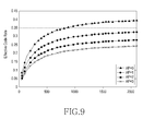
- FIG. 9 is a graph illustrating a code rate when a number of additional parity bits is calculated using Equation (15), according to an embodiment of the present invention.
- Equation (19) K sig K sig + N tx_parity + N add_parity
- N tx_parity indicates the number of parity bits of the first part 814 of FIG. 8
- N ldpc + M IR -N punc 6480 - N punc
- N add_parity indicates the number of additional parity bits of the part 816 of FIG. 8 .
- the IR parity bits 804 of the LDPC code in FIG. 8 may be selectively used. That is, the parity bits 802 are preferentially generated for input information word bits, and the IR parity bits 804 may be generated only when the IR parity is necessary, thereby improving encoding/decoding efficiency.
- Equation (20) if N punc is a positive integer, only the parity bits 802 are generated and only N punc parity bits of the parity bits 802 are punctured. However, if N punc is a negative value, both the parity bits 802 and the IR parity bits 804 are generated, and then only (M IR + N punc ) bits of the IR parity bits 804 are punctured.
- N punc obtained using Equations (10) to (12), based on Equation (20)
- parity bits are punctured.
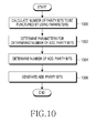
- FIG. 10 is a flowchart illustrating a procedure for determining a number of two types of parity bits according to an embodiment of the present invention.
- step 1000 the number of parity bits to be punctured is calculated using Equations (7) and (8) or Equations (9) to (12).
- step 1002 parameters, ⁇ , I l , and N tx_parity , which are used in Equations (13), (15), and (17), are determined.
- step 1002 already-determined ⁇ or I l may be used, and I l is expressed as K in Equations (17) and (18). As described above, K may be indicated by separate signaling 'L1_AP_RATIO'.
- step 1004 the number of additional parity bits, N add_parity , is determined based on Equation (13) or Equations (17) and (18), using the parameters determined in step 1002.
- step 1006 the additional parity bits are configured according to the calculated number of additional parity bits.
- FIG. 11 is a block diagram of a transmission end according to an embodiment of the present invention.
- the transmission end includes an encoder 1101, a puncturer 1103, a controller 1105, a modulator 1107, a Radio Frequency (RF) processor 1109, and selectively, an additional parity configuring unit 1111.
- an encoder 1101 a puncturer 1103, a controller 1105, a modulator 1107, a Radio Frequency (RF) processor 1109, and selectively, an additional parity configuring unit 1111.
- RF Radio Frequency
- the encoder 1101 outputs encoded bits generated by encoding information word bits for transmission. For example, when a BCH/LDPC code is used, the encoder 1101 encodes BCH information bits having K bch bits to generate a BCH codeword having K ldpc bits. Thereafter, the encoder 1101 performs LDPC-encoding on the BCH codeword, thus generating and outputting an LDPC codeword having N ldpc bits.
- the encoder 1101 generates and outputs an LDPC codeword having (N ldpc + M IR ) bits.
- the BCH information bits having K bch bits may be configured by padding (K bch - K sig ) '0' bits into K sig input information bits.
- the padded (K bch - K sig ) '0' bits are not to be transmitted.
- the puncturer 1103 punctures a codeword provided from the encoder 1101 according to a puncturing pattern and a puncturing bit length (K bch - K sig ), which are provided from the controller 1105.
- the controller 1105 calculates the puncturing bit length according to the number of information bits to control the puncturer 1103. For example, the controller 1105 determines A and B according to the number of input information bits (or the number of signaling bits) for transmission at the transmission end, and provides the determined A and B to the puncturer 1103.
- the controller 1105 obtains the number of bits to be punctured from the determined parameters A and B, and provides the obtained number of bits to be punctured to the puncturer 1103.
- the modulator 1107 modulates, according to a corresponding modulation scheme, and outputs a signal provided from the puncturer 1103.
- the RF unit 1109 converts the modulated signal provided from the modulator 1107 into a high-frequency signal and transmits the high-frequency signal through an antenna.
- the controller 1105 determines the number of additional parity bits, as illustrated in FIG. 10 , and provides the determined number of additional parity bits to the additional parity configuring unit 1111.
- the additional parity configuring unit 1111 configures the additional parity bits and provides them to the modulator 1107. It should be noted that additional parities generated in the current frame are transmitted through a previous frame.
- (K ldpc - K sig ) bits are shortened for an input information bit length K sig . If a BCH code is concatenated, (K bch - K sig ) bits are shortened for a BCH information bit length K bch .
- FIG. 12 is a block diagram of a reception end according to an embodiment of the present invention.
- the reception end includes an RF unit 1200, a demodulator 1202, a shortening/puncturing processor 1204, a decoder 1206, a controller 1208, and selectively, an additional parity processing unit 1210.
- the RF unit 1200 receives a signal transmitted from the RF unit 1109 of the transmission end and provides the signal to the demodulator 1202.
- the demodulator 1202 demodulates the signal provided from the RF unit 1200 by utilizing a demodulation scheme corresponding to a modulation scheme used in the modulator 1107 of the transmission end. For example, the demodulator 1202 obtains a Log Likely Ratio (LLR), by taking a log of a ratio of a probability of each bit being 1 to a probability of each bit being 0 for each of shortened/punctured encoded bits and additional parity bits transmitted from the modulator 1107, and provides the obtained LLR to the shortening/puncturing processor 1204 and the additional parity processing unit 1210.
- LLR Log Likely Ratio
- the additional parity processor 1201 is optional, in that it is not used when additional parity is not received.
- the shortening/puncturing processor 1204 receives an output signal of the demodulator 1202, generates values corresponding to shortening and puncturing with respect to the bits shortened and punctured by the transmission end, and pads the values to the output signal of the demodulator 1202. For example, for a shortened bit, an LLR value is the (+) or (-) maximum value among a decoder input value, and for a punctured bit, an LLR value is '0'.
- the shortening/puncturing processor 1204 receives information about the number of shortened and punctured bits and index from the controller 1208. That is, the controller 1208 calculates a puncturing bit length according to the number of information bits of the encoder 1101 of the transmission end and controls the shortening/puncturing processor 1204.
- the controller 1208 determines A and B according to the number of bits of signaling information for transmission at the transmission end, as illustrated in FIG. 6 , and provides the determined A and B to the shortening/puncturing processor 1204.
- the controller 1208 obtains the number of bits to be punctured from the determined parameters A and B and provides the obtained number of bits to be punctured to the shortening/puncturing processor 1204.
- Information about the number of input information bits input to the encoder of the transmission end may be transmitted to the controller 1208 of the receiver through, for example, additional signaling.
- the decoder 1206 receives and decodes output values of the shortening/puncturing processor 1204 to reconstruct information word bits. For example, when a BCH/LDPC code is used, the decoder 1206 receives N ldpc or (N ldpc +M IR ) LLR values and performs LDPC-decoding thereon to reconstruct K ldpc bits, and then reconstruct K bch information word bits through BCH decoding.
- the controller 1208 determines the number of additional parity bits, as illustrated in FIG. 10 , and provides the determined number of additional parity bits to the additional parity processing unit 1210.
- the additional parity processing unit 1210 receives LLR values for the additional parity bits generated by the transmission end from the demodulator 1202 and provides the LLR values to the decoder 1206.
- the decoder 1206 performs decoding by using both the values provided from the shortening/puncturing processor 1204 and the values provided from the additional parity processing unit 1210. It should be noted that additional parities received in the current frame are used in decoding of the next frame according to processing at the transmitter. That is, in decoding of a code received in the current frame, additional parity bits received in the previous frame are used.
Landscapes
- Engineering & Computer Science (AREA)
- Computer Networks & Wireless Communication (AREA)
- Signal Processing (AREA)
- Error Detection And Correction (AREA)
Abstract
Description
- The present invention relates generally to transmission and reception of information in a broadcasting/communication system, and more particularly, to a method and apparatus for controlling a code rate according to transmission and reception of signaling information in a broadcasting/communication system.
- A broadcasting/communication system may experience poor link performance due to noise, a fading phenomenon, and Inter-Symbol Interference (ISI). Thus, to implement high-speed digital broadcasting/communication systems, which require high data throughput and reliability, development of a technique for overcoming noise, fading, and ISI is essential. To address these issues, research is currently being conducted on an error-correcting code, e.g., a Low-Density Parity Check (LDPC) code, for improving the reliability of broadcasting/communication by efficiently restoring distortion of information to an original state.
- More specifically, an LDPC encoder receives LDPC information bits (or an LDPC information word or an LDPC uncoded block) having Kldpc bits to generate LDPC coded bits (or an LPDC code word, an LDPC codeword, or an LDPC coded block) having Nldpc bits. If the length of LDPC information bits input to the LDPC encoder, Kldpc, is shorter than the length of an input information bits (or input information word) to be encoded, Ksig, then a transmission end performs encoding after a shortening process. If the number of parity bits used by the transmission end, i.e., a parity bit length, Ntx_parity, is shorter than the length of parity bits output from the encoder, (Nparity=Nldpc-Kldpc), the transmission end punctures the parity bits output from the encoder by (Nparity - Ntx_parity ).
- If the shortening bit length increases, a code rate decreases, such that Bit Error Rate(BER)/Frame Error Rate (FER) performance may be improved in comparison to a code before shortening. However, if the puncturing bit length increases, a code rate also increases, such that the BER/FER performance may be degraded in comparison to a code before puncturing. Therefore, to maintain similar performance regardless of the length of an information word for system stability, a technique for selecting the appropriate number of puncturing bits according to the length of an information word is required.
- Accordingly, the present invention is designed to address at least the problems and/or disadvantages described above and to provide at least the advantages described below.
- An aspect of the present invention is to provide a method and apparatus for transmitting and receiving information in a broadcasting/communication system.
- Another aspect of the present invention is to provide a method and apparatus for controlling a code rate in a broadcasting/communication system.
- Another aspect of the present invention is to provide a method and apparatus for selecting a shortening/puncturing rate according to a length of an information word in a broadcasting/communication system.
- Another aspect of the present invention is to provide a method and apparatus for determining a number of bits to be punctured according to a length of an input information word in a broadcasting/communication system.
- In accordance with an aspect of the present invention, a method for transmitting information in a broadcasting/communication system is provided. The method includes comparing a number of bits of an information word to be transmitted with a predetermined threshold value, if the number of bits of the information word is less than the threshold value, determining a first parameter pair, if the number of bits of the information word is not less than the threshold value, determining a second parameter pair, determining a number of bits to be punctured based on one of the first parameter pair and the second parameter pair, and puncturing the determined number of bits to be punctured, with respect to parity bits of a codeword generated by encoding the information word.
- In accordance with another aspect of the present invention, an apparatus for transmitting information in a broadcasting/communication system is provided. The apparatus includes an encoder for encoding an information word to be transmitted and outputting a codeword; a controller for comparing a number of bits of the information word with a predetermined threshold value, determining a first parameter pair, if the number of bits of the information word is less than the predetermined threshold value, determining a second parameter pair, if the number of bits of the information word is not less than the predetermined threshold value, and determining a number of bits to be punctured, based on one of the first parameter pair and the second parameter pair; and a puncturer for puncturing the determined number of bits to be punctured, with respect to parity bits of the codeword.
- In accordance with another aspect of the present invention, a method for receiving information in a broadcasting/communication system is provided. The method includes comparing a number of bits of an information word transmitted by a transmission end with a predetermined threshold value, determining a first parameter pair, if the number of bits of the information word is less than the predetermined threshold value, determining a second parameter pair, if the number of bits of the information word is not less than the predetermined threshold value, determining a number of bits to be punctured, based on one of the first parameter pair and the second parameter pair, generating values corresponding to bits punctured by the transmission end and padding the generated values to a modulated signal of a received signal to generate a decoder input by using the determined number of bits to be punctured, and decoding the decoder input to reconstruct information word bits.
- In accordance with another aspect of the present invention, an apparatus for receiving information in a broadcasting/communication system is provided. The apparatus includes a demodulator for demodulating a received signal; a controller for obtaining information about a number of bits of an information word transmitted from a transmission end, comparing the number of bits of the information word transmitted by the transmission end with a predetermined threshold value, determining a first parameter pair, if the number of bits of the information word is less than the predetermined threshold value, determining a second parameter pair, if the number of bits of the information word is not less than the predetermined threshold value, and determining a number of bits to be punctured, based on one of the first parameter pair and the second parameter pair; a puncturing processor for generating values corresponding to the bits punctured by the transmission end by using the determined number of bits to be punctured, and padding the generated values to an output signal of the demodulator; and a decoder for receiving and decoding output values of the puncturing processor to reconstruct information word bits.
- The above and other aspects, features, and advantages of certain embodiments of the present invention will be more apparent from the following detailed description taken in conjunction with the accompanying drawings, in which:
-
FIG. 1 is a graph illustrating a change in a code rate according to an embodiment of the present invention; -
FIGs. 2 and3 are graphs illustrating efficiency of an LDPC code according to an embodiment of the present invention; -
FIG. 4 is a graph illustrating a change in an effective code rate according to an embodiment of the present invention; -
FIG. 5 is a graph illustrating efficiency of an LDPC code according to an embodiment of the present invention; -
FIG. 6 is a flowchart illustrating a procedure for puncturing parity bits based on an information bit length according to an embodiment of the present invention; -
FIG. 7 is a diagram illustrating a frame structure for transmitting two types of parity bits according to an embodiment of the present invention; -
FIG. 8 is a diagram illustrating a structure of an LDPC code for supporting transmission of parity bits according to an embodiment of the present invention; -
FIG. 9 is a graph illustrating a change in an effective code rate according to an embodiment of the present invention; -
FIG. 10 is a flowchart illustrating a procedure for determining a number of two types of parity bits according to an embodiment of the present invention; -
FIG. 11 a block diagram illustrating a transmission end according to an embodiment of the present invention; and -
FIG. 12 is a block diagram illustrating a receiving end according to an embodiment of the present invention. - Various embodiments of the present invention will be described in detail below with reference to the accompanying drawings. Well-known functions and structures will not be described if they may unnecessarily obscure the subject matter of the present invention. Further, the terms used herein are defined based on functions in the present invention and may vary according to users, operator intention, or usual practices. Therefore, definitions of the terms should be made based on the content throughout the specification.
- Although the following description of the present invention is based on a Digital Video Broadcasting the 2nd Generation Terrestrial (DVB-T2) system, which is the Europe digital broadcasting standard, and a Digital Video Broadcasting Next Generation Handheld (DVB-NGH) system, which is being currently standardized, the present invention is equally applied to other systems.
- Additionally, although the following description controls a code rate corresponding to transmission of signaling information, the present invention is also applicable to the transmission of other information.
- In a transmission end of a broadcasting/communication system, an LDPC encoder receives Kldpc LDPC information bits, generates Nparity parity bits, and outputs Nldpc (=Kldpc + Nparity) LDPC coded bits. In the following description, for convenience' sake, the input and output of "bits" will be described, but the same description is also applied to the input and output of symbols.
- When signaling bits of a variable length are input to an encoder, a transmission end may perform shortening and/or puncturing (hereinafter referred to as "shortening/puncturing"). That is, if a length of LDPC information bits of the LDPC encoder is Kldpc and signaling bits having a bit length of Ksig are input to the LDPC encoder, (Kldpc- Ksig) bits are shortened. Herein, shortening means padding (Kldpc-Ksig) '0' bits to the signaling bits for LDPC encoding, and after LDPC encoding, deleting the padded '0' bits, or reducing the size of a parity check matrix of the LDPC encoder, which has the same effect as shortening based on the padding and deletion. Further, puncturing means excluding some of encoding bits, especially, parity bits, from a transmission.
- The transmission end of the broadcasting/communication system may use two concatenated encoders. For example, an encoder that concatenates a Bose, Chaudhuri, Hocquenghem (BCH) code with an LDPC code, i.e., a BCH/LDPC encoder, receives BCH information bits (BCH information or information bits) having Kbch bits and outputs BCH coded bits (or BCH codeword or a BCH coded block) having Nbch bits. Nbch is equal to the number of LDPC information bits, Kldpc, and the Nbch bits may also be referred to as LDPC information bits (or an LDPC uncoded block), which is information input to the LDPC encoder. The BCH coded bits, i.e., the LDPC information bits, are input to the LDPC encoder and are output as LDPC coded bits, an LDPC coded block, or an LDPC codeword having a length of Nldpc.
- When an information word, which includes signaling bits having a variable length, is input to an encoder, a transmission end performs shortening/puncturing with respect to a codeword output from the encoder. That is, signaling bits having a bit length of Ksig are input to the BCH/LDPC encoder and (Kbch- Ksig) bits are shortened. As described above, shortening means that (Kbch- Ksig) '0' bits are padded to the input signaling bits and are BCH/LDPC encoded, and then the padded '0' bits are deleted.
- As described above, shortening reduces a code rate, such that as the number of bits to be shortened (i.e., a shortening bit length) increases, encoding performance improves. However, when signaling information is encoded, it is preferable that encoding performance should not vary with the length of input information. That is, when reception power in a receiver is constant, it is preferable that performance should not differ with the length of input information word. Therefore, by adjusting the number of bits to be punctured (i.e., a puncturing bit length) according to the number of bits to be shortened, stable encoding performance is provided. The number of bits to be punctured is determined according to a bit length of input information word, i.e., a bit number of the input information word, such that the number of bits to be punctured depends on the bit number of the input information word.
- Hereinbelow, embodiments for determining an input parameter used for puncturing, i.e., the number of bits to be punctured, Npunc, will be described.
- In one embodiment, Npunc may be calculated using one of Equations (1) to (4).
- Equation (1) is used when a BCH code is concatenated and Equation (2) is used when a BCH code is not concatenated. That is, when the BCH code is concatenated, the number of bits to be shortened is (Kbch- Ksig), such that Npunc may be calculated using Equation (1).

- When the BCH code is not concatenated, the number of bits to be shortened is (Kldpc- Ksig), such that Npunc may be calculated using Equation (2).

- In Equations (1) and (2), A indicates a rate of the number of bits to be shortened to the number of bits to be punctured, and (Kbch- Ksig) and (Kldpc- Ksig) indicate the number of bits to be shortened. Kbch indicates the number of BCH information bits (i.e., an information bit length) input to generate BCH coded bits including Kldpc bits through BCH encoding. Kldpc indicates the number of LDPC information bits input to generate the LDPC coded bits. Ksig indicates a bit length of an information word input to the encoder before shortening. B indicates a correction factor. The operation └x┘ indicates a floor function and means the largest integer less than or equal to x.
- When the number of bits to be punctured is calculated based on Equations (1) or (2), a lower code rate can be obtained than when shortening and puncturing are not performed. In the foregoing description, if B is 0, it can be omitted.
- Alternatively, when Npunc is calculated using Equations (3) or (4), a lower code rate can be obtained than when shortening and puncturing are not performed.
- More specifically, when the BCH code is concatenated, the number of bits to be shortened is (Kbch- Ksig), such that Npunc may be calculated using Equation (3).

- When the BCH code is not concatenated, the number of bits to be shortened is (Kldpc- Ksig), such that Npunc may be calculated using Equation (4).

- In Equations (3) and (4), A indicates a rate of the number of bits to be shortened to the number of bits to be punctured, and (Kbch- Ksig) and (Kldpc- Ksig) indicate the number of bits to be shortened. Kbch indicates the number of BCH information bits (i.e., an information bit length) input to generate BCH coded bits composed of Kldpc bits through BCH encoding. Kldpc indicates the number of LDPC information bits input to generate the LDPC coded bits. Ksig indicates a bit length of an information word input to the encoder before shortening. B indicates a correction factor. K sig_min indicates a bit length of the shortest information word among information words that can be input to the encoder.
- In Equations (3) and (4), Npunc is smaller than the number of parity bits, Nparity, only when a condition of B < Nparity - A(Klapc- K sig_min) is satisfied.
- In Equations (1) to (4), Npunc may change according to the parameters A and B. Accordingly, a code rate may change according to A and B. When Kldpc bits are input and Nldpc coded bits are output, a code rate of an LDPC code, R, may be calculated using Equation (5).

- For Ksig input information word bits, an effective code rate Reff after shortening and puncturing is calculated using Equation (6).

- In Equation (6), Nbch_parity indicates the number of parity bits of a BCH code, which is 0 when a BCH code is not used.
-
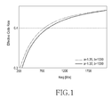
FIG. 1 is a graph illustrating a change in an effective code rate according to an embodiment of the present invention. Specifically,FIG. 1 illustrates a change in a code rate for Kbch=2100, Kldpc=2160, and Nldpc=8640, when A=1.35 and B=3320 are applied to Equation (3) and when A=1.32 and B=3320 are applied to Equation (3). As is shown, a code rate for transmission of information varies with A, i.e., as A increases, a code rate also increases. -
FIG. 2 illustrates a Frame Error Rate (FER) of a codeword with respect to various information bit lengths of 280, 396, 880, 1350, 1550, 1670, and 1900 for A=1.35 and B=3320. - Referring to
FIG. 2 , when the number of input information bits, Ksig, is 280, performance degradation occurs. Therefore, for FER=10e-4, a performance difference between the best performance and the worst performance is 0.7dB. -
FIG. 3 illustrates an FER of a codeword with respect to various information bit lengths of 280, 396, 880, 1350, 1550, 1670, 1900 for A=1.32 and B=3320. - Referring to
FIG. 3 , a code rate is lower than that inFIG. 2 , such that overall performance improvement is achieved. In particular, when the number of input information bits, Ksig, is 1350, performance is much better than in other cases. It can also be seen that for FER=10e-4, a performance difference between the best performance and the worst performance is 0.7dB. - As described above, it is preferable that encoding performance does not differ much with an input information bit length. Thus, a method for adjusting A and B in Equations (1) to (4) according to an input information bit length is required.
- Therefore, in accordance with an embodiment of the present invention, Npunc is determined using Equations (7) and (8).


- In Equations (7) and (8), different values of A and B, i.e., A 1 and B 1 or A 2 and B 2 are used according to an input information bit length.
- If B1 is integer, the Equation (7) can be modified to following Equation (7a).

- If A1=C+D (where C is integer and D is real number), the Equation (7) can be modified to following Equation (7b).

- Also, the Equation (8) can be modified in similar to the Equations (7a) and (7b).
- In Equations (7) and (8), a case of an input information bit length being less than a predetermined threshold value Kth and a case of the input information bit length being greater than the threshold value Kth are divided. However, a plurality of threshold values may be used to divide a case of the input information bit length, such that two or more pairs of A and B may be used.
- Kth may be experimentally determined not to cause an encoding performance difference with Npunc. In particular, a value corresponding to a case where performance is relatively good or a case where performance is relatively bad is determined as Kth. In addition, different parameter pairs (A 1 , B 1) and (A 2 , B 2) are determined such that for Ksig=Kth, Npunc values are equal to each other.
- As described above, the number of bits to be punctured is preferably adjusted according to the number of bits to be shortened, and the number of bits to be shortened is determined according to a bit length of an input information word. Thus, A 1 and A 2 indicating ratios of the number of bits to be shortened to the number of bits to be punctured may be constant values determined according to a bit length of an input information word. Therefore, B 1 and B 2 may be determined as constant values.
- Once Npunc is determined as described above, the transmission end punctures parity bits among coded bits generated by encoding input information bits with Npunc.
-
FIG. 4 is a graph illustrating a change in an effective code rate according to an embodiment of the present invention, where A=1.35 and B=3320 in Equation (3), and A=1.32 and B=3320 in Equation (3) are compared with using Equations (7) and (8), which is indicated as "proposed". - Specifically, "proposed" indicates that Kbch=2100, Kldpc=2160, Nldpc=8640, A 1=1.3, B 1 =3357, A 2=1.35, B 2=3320, and Kth=1350 are applied to Equation (7). As illustrated in
FIG. 4 , when Ksig is more than 1350, which is equal to Kth, the "proposed" case shows the same code rate as when A=1.35 and B=3320 in Equation (3). -
FIG. 5 is a graph illustrating an FER according to an embodiment of the present invention. Specifically,FIG. 5 illustrates FER performance with respect to various information bit lengths of 280, 396, 880, 1350, 1550, 1670, and 1900. - Referring to
FIG. 5 , for an input information bit length of 280, a code rate is lower than illustrated inFIG. 2 , such that performance is better. For an input information bit length of 1350, a code rate is higher than illustrated inFIG. 3 , such that performance degradation occurs. Therefore, an overall performance difference is 0.3dB and an encoding performance difference is reduced when compared toFIGs. 2 and3 . - In the description above, the number of bits to be punctured, Npunc, is calculated by using the foregoing equations. However, in the following description, a value obtained using the foregoing equations is assumed to be a temporary value of Npunc, i.e., a temporary number of bits to be punctured, Npunc_temp, and through several processes, Npunc is obtained more precisely.
- In accordance with an embodiment of the present invention, the transmission end, when performing puncturing by using Npunc, may more precisely adjust Npunc according to additional parameters, e.g., the number of BCH parity bits, a modulation order, etc. Hereinafter, a procedure for calculating the final number of bits to be punctured using Npunc_temp will be described.
- The temporary number of bits to be punctured, Npunc_temp, is calculated using Equation (9), which is substantially the same as the above-described Equation (7) and the description related thereto.

- An LDPC code concatenated with a BCH code is used, and in Equation (9), values (A 1, B 1)=(1.3, 3357) and (A 2, B 2)=(1.35, 3320) of
FIG. 4 are used. - The temporary number of bits to be encoded, Npost_temp , is calculated using Npunc_temp as shown in Equation (10).

- In Equation (10), Ksig indicates the number of input information bits as described above, and for example, it may indicate the number of signaling information bits. Nbch_parity indicates the number of BCH parity bits, and N ldpc_parity_ext_4K indicates a constant value determined according to a type of an LDPC code.
- Taking Npost_temp and a modulation order into account, the final number of bits to be encoded (a bit number of each LDPC block) is calculated using Equation (11a):

- In Equation (11 a), η MOD indicates a modulation order, which is 1, 2, 4, and 6 for Binary Phase Shift Keying (BPSK), Quadrature PSK (QPSK), 16-ary Quadrature Amplitude Modulation (16-QAM), and 64-ary QAM (64-QAM), respectively.
- Determining the number of encoded bits of each information word block, Npost, as shown in Equation (11a), causes Npost to be a multiple of the number of columns of a block interleaver. The block interleaver, although not being shown and additionally described, is used when bits of each LDPC block is bit-interleaved later.
- When the block interleaver is not used, for example, when only BPSK and QPSK are used, Equation (11a) can be converted into Equation (11b).

- The number of bits to be punctured among parity bits of each LDPC block, Npunc, is calculated using Equation (12).

-
FIG. 6 is a flowchart illustrating a procedure for puncturing parity bits based on an input information bit length according to an embodiment of the present invention. - Referring to
FIG. 6 , instep 600, the number of input information bits including signaling information for transmission (i.e., an input information bit length) is determined. Instep 602, the transmission end checks parameters for calculating the number of bits to be punctured, i.e., a puncturing bit length. That is, the transmission end determines whether to select (A 1 , B 1) or (A 2 , B 2) according to the input information bit length using Equations (7) and (8). Although not shown, one of two or more predetermined parameter pairs may be selected according to the input information bit length. Alternatively, instep 602, the transmission end may obtain parameter values (A 1, B 1)=(1.3, 3357) or (A 2 , B 2)=(1.35, 3320) to be used in Equation (9) according to a result of comparison of the input information bit length with a predetermined threshold value of 1350. - In
step 604, the number of parity bits to be punctured (i.e., a puncturing parity bit length) is calculated based on the determined parameters, e.g., using Equations 7 and 8 or Equations (9) to (12). Instep 606, parity bits of a codeword are punctured based on the calculated puncturing parity bit length. - The parity bits generated with respect to the signaling bits, which are the input information bits, may be transmitted in a distributed manner through the same frame as a frame in which the signaling bits are transmitted and a preceding frame. The parity bits transmitted through the same frame as that which carries the signaling bits will be referred to herein as a first parity, and the parity bits transmitted through the preceding frame will be referred to herein as a second parity or an additional parity.
-
FIG. 7 is a diagram illustrates a frame structure for transmitting two types of parity bits according to an embodiment of the present invention. - Referring to
FIG. 7 , Layer-1 signaling bits are transmitted through an ith frame 702; afirst parity 710 generated for signaling bits is transmitted through the ith frame 702, together with the signaling bits; and anadditional parity 712 is transmitted through an (i-1)thframe 700. - In accordance with an embodiment of the present invention, a reception end performs decoding based on the signaling bits and the
first parity 710 received through the ith frame 702. If decoding fails, the reception end also performs decoding using theadditional parity 712 received through the (i-1)thframe 700. - In accordance with another embodiment of the present invention, if decoding with respect to the signaling bits and the
first parity 710 fails, the reception end determines that decoding with respect to the signaling bits fails, stores an additional parity included in the ith frame 702, and then receives an (i+1)th frame. - In accordance with yet another embodiment of the present invention, the reception end stores the
additional parity 712 received through the (i-1)thframe 700 at all times, and performs decoding based on the signaling bits and thefirst parity 710 received through the ith frame 702 and the storedadditional parity 712. - Herein below, a method for determining the number of additional parity bits will be described in more detail.
- In accordance with an embodiment of the present invention, the number of additional parity bits may be expressed using Equation (13).

- In Equation (13), α · Il indicates a ratio of the number of first parity bits to the number of additional parity bits, where α is a fixed value, Ii may be selected between 0 and L-1, and L1 indicates an L1 additional parity ratio. Ii may be transmitted through separate signaling 'L1_AP_RATIO'. When Ii =0, additional parity bits are not used. Ntx_parity indicates the number of parity bits transmitted through the same frame as that for an information word (i.e., the first parity bits), and may also mean the number of parity bits to be actually transmitted. In this case, Ntx_parity may be calculated as Nparity - Npunc.
-
FIG. 8 is a diagram illustrating an LDPC code for supporting parity transmission according to an embodiment of the present invention. - Referring to
FIG. 8 , an LDPC codeword includes KldpcLDPC information bits 800, Nparity parity bits 802, and MIR Incremental Redundancy (IR)parity bits 804. For convenience, the Nparity parity bits 802 and the MIRIR parity bits 804 are collectively referred to herein as parity bits. The structure of the LDPC code illustrated inFIG. 8 is designed considering theparity bits 802. Therefore, in puncturing, theIR parity bits 804 are punctured. The LDPC code ofFIG. 8 may be expressed as parity bits, without discrimination between theparity bits 802 and theIR parity bits 804. - To encode signaling
bits 806, theLDPC information bits 800 may include the signalingbits 806,parity bits 807 for a BCH code, and '0'padding bits 808 for shortening. Theparity bits 802 and theIR parity bits 804 includenon-punctured parity bits 810, and puncturedparity bits 812. Herein, a detailed position (i.e., an index) of each bit is not relevant to the subject matter of the present invention, , i.e., which bits between theparity bits 802 and theIR parity bits 804 are to be punctured and which bits there between are not to be punctured. Accordingly, a specific puncturing pattern, will not be described herein. - The
parity bits 807 of the BCH code exist when a concatenated code of the BCH code and the LDPC code is used, and theBCH parity bits 807 will be omitted when only the LDPC code is used. - The signaling
bits 806, theBCH parity bits 807, and thenon-punctured parity bits 810 form afirst part 814, which is later transmitted through the ith frame 702, as illustrated inFIG. 7 . Some of the puncturedparity bits 812 form anadditional parity 816, which is later transmitted through the (i-1)thframe 700, as illustrated inFIG. 7 . That is, some of the puncturedparity bits 812 are the same as theadditional parities - The
additional parity 708 may be determined a number of ways. For example, the puncturedparity bits 812 may be preferentially selected as an additional parity. - For Kbch=2100, Kldpc=2160, Nldpc=4320, and MIR = 4320, Rldpc = Kldpc/Nldpc = 1/2 and RIR = Kldpc/(Nldpc+Mldpc) = 1/4. In this case, according to an embodiment of the present invention, Npunc may be calculated, based on Equation 7, using Equation (14) below.

- In Equation (14), A 1=1.3, B 1=3357, A 2=1.35, B2=3320, and Kth=1350. Therefore, among the
parity bits 802 and theIR parity bits 804, Npunc parity bits based on Equation (14) are punctured. - In accordance with another embodiment of the present invention, Npunc parity bits obtained based on Npunc_temp of Equation (9), using Equations (10) to (12), may be punctured.
- Detailed values of parameters used to calculate Npunc may be determined according to a modulation scheme used for transmission and the number of Orthogonal Frequency Division Multiplexing (OFDM) symbols. For example, when 2n- Quadrature Amplitude Modulation (QAM) is used as a modulation scheme, the number of bits to be transmitted, (Ksig+ Nbch_parity +Nparity+MIR-Npunc) is a multiple of n. Herein, Ksig indicates the number of input signaling information bits, Nbch_parity indicates the number of parity bits of a BCH code, and n indicates an order of a modulation scheme.
- The number of bits of the
additional parity 712 ofFIG. 7 or theadditional parity 816 ofFIG. 8 may be calculated using Equation (15).
- In Equation (15), I0=0, I1=1, I2=2, and I3=3. Further, α =0.35 is applied to Equation (13), where α is a value selected to satisfy Equation (16) below.

- That is, α is determined to be a maximum value among values in which a sum of the number of first parity bits, Ntx_parity, and the number of additional parity bits, Nadd_parity, which are transmitted when Il is the maximum value IL-1 and Ksig is the maximum length among input information bits, K sig_max, that is, (Ntx_parity + Nadd_parity ) is maximal and the sum is less than (Nparity + MIR).
- When the maximum length among the input information bits, K sig_max, is 2100, Npunc = 3320, such that Ntx_parity = 3160, and when Il is the maximum value IL-1 = I3 = 3, Nadd_parity = 0.35×3×3160 = 3318, such that Ntx_parity + Nadd_parity = 6478, which is less than Nparity + MIR = 6480.
- Hereinafter, an embodiment for obtaining more precise Nadd_parity considering a modulation scheme used for transmission based on Nadd_parity obtained through the foregoing equations will be described.
- Equation (16) assumes that the BPSK modulation scheme is used. That is, α is determined such that the number of first parity bits and the number of additional parity bits transmitted when using the BPSK modulation scheme is used is less than Nparity + MIR. Therefore, when another modulation scheme, e.g., QPSK, 16-QAM, or 64-QAM is used, correction with respect to Nadd_parity is required such that the number of first parity bits and the number of additional parity bits is less than Nparity + MIR. Therefore, the number of temporary additional parity bits may be obtained using Equation (17).

- In Equation (17), K indicates an L1 additional parity ratio, and is another expression of Ii from Equations (13) and (15). In accordance with an embodiment of the present invention, K may be transmitted from the transmitter to the receiver through signaling 'L1_AP_RATIO'. For example, 'L1_AP_RATIO' is a 2-bit parameter, and when this parameter is '00', K=0; for the parameter of '01', K=1; K=2 for the parameter of '10'; and K=3 for the parameter of '11'.
- Taking Nadd_parity_temp of Equation (17) and a modulation order, the final number of additional parity bits may be calculated using Equation (18a).

- In Equation (18a), η MOD indicates a modulation order, which is 1, 2, 4, and 6 for BPSK, QPSK, 16-QAM, and 64-QAM, respectively.
- The number of additional parity bits, N add_ parity, is adjusted in Equation (18a) to cause Nadd_parity to be a multiple of the number of columns of the block interleaver. The block interleaver is used when each bit of the additional parity is bit-interleaved.
- When the block interleaver is not used, e.g., when only BPSK and QPSK are used, Equation (18a) can be converted into Equation (18b).

- Nadd_parity is determined according to the number of OFDM symbols used for transmission.
- Information about the number of additional parity bits can be transmitted from the transmitter to the receiver through a signaling parameter 'L1_AP_SIZE'. If a plurality of LDPC coded blocks are used for transmission, L1_AP_SIZE indicates a product of the number of coded blocks and Nadd_parity. For example, when two coded blocks are used, 'L1_AP_SIZE' may indicate 2 × Nadd_parity . The receiver may know the number of additional parity bits from that signaling parameter.
-
FIG. 9 is a graph illustrating a code rate when a number of additional parity bits is calculated using Equation (15), according to an embodiment of the present invention. - Specifically, the code rate is calculated using Equation (19).

- In Equation (19), Ntx_parity indicates the number of parity bits of the
first part 814 ofFIG. 8 , andNldpc + MIR-Npunc = 6480 - Npunc. Nadd_parity indicates the number of additional parity bits of thepart 816 ofFIG. 8 . - In
FIG. 9 , Additional Parity (AP)=0 corresponds to a code rate for I0=0 in which the additional parity is not used, AP=1 corresponds to a code rate for I1=1, AP=2 corresponds to a code rate for I2=2, and AP=3 corresponds to a code rate for I3=3. - In accordance with another embodiment of the present invention, the
IR parity bits 804 of the LDPC code inFIG. 8 may be selectively used. That is, theparity bits 802 are preferentially generated for input information word bits, and theIR parity bits 804 may be generated only when the IR parity is necessary, thereby improving encoding/decoding efficiency. - As described above, the
parity bits 802 are preferentially generated for input information bits, and for theparity bits 802, Npunc may be calculated based on Equation (7), as shown in Equation (20).
- In Equation (20), if Npunc is a positive integer, only the
parity bits 802 are generated and only Npunc parity bits of theparity bits 802 are punctured. However, if Npunc is a negative value, both theparity bits 802 and theIR parity bits 804 are generated, and then only (MIR + Npunc) bits of theIR parity bits 804 are punctured. - According to another embodiment of the present invention, Npunc (obtained using Equations (10) to (12), based on Equation (20)) parity bits are punctured.
-
FIG. 10 is a flowchart illustrating a procedure for determining a number of two types of parity bits according to an embodiment of the present invention. - Referring to
FIG. 10 , instep 1000, the number of parity bits to be punctured is calculated using Equations (7) and (8) or Equations (9) to (12). Instep 1002, parameters, α, Il , and Ntx_parity, which are used in Equations (13), (15), and (17), are determined. Instep 1002, already-determined α or Il may be used, and Il is expressed as K in Equations (17) and (18). As described above, K may be indicated by separate signaling 'L1_AP_RATIO'. - In
step 1004, the number of additional parity bits, Nadd_parity, is determined based on Equation (13) or Equations (17) and (18), using the parameters determined instep 1002. Instep 1006, the additional parity bits are configured according to the calculated number of additional parity bits. -
FIG. 11 is a block diagram of a transmission end according to an embodiment of the present invention. - Referring to
FIG. 11 , the transmission end includes anencoder 1101, apuncturer 1103, acontroller 1105, amodulator 1107, a Radio Frequency (RF)processor 1109, and selectively, an additionalparity configuring unit 1111. - The
encoder 1101 outputs encoded bits generated by encoding information word bits for transmission. For example, when a BCH/LDPC code is used, theencoder 1101 encodes BCH information bits having Kbch bits to generate a BCH codeword having Kldpc bits. Thereafter, theencoder 1101 performs LDPC-encoding on the BCH codeword, thus generating and outputting an LDPC codeword having Nldpc bits. - Alternatively, the
encoder 1101 generates and outputs an LDPC codeword having (Nldpc + MIR) bits. - Although not illustrated, the BCH information bits having Kbch bits may be configured by padding (Kbch - Ksig) '0' bits into Ksig input information bits. The padded (Kbch - Ksig) '0' bits are not to be transmitted.
- The
puncturer 1103 punctures a codeword provided from theencoder 1101 according to a puncturing pattern and a puncturing bit length (Kbch - Ksig), which are provided from thecontroller 1105. Thecontroller 1105 calculates the puncturing bit length according to the number of information bits to control thepuncturer 1103. For example, thecontroller 1105 determines A and B according to the number of input information bits (or the number of signaling bits) for transmission at the transmission end, and provides the determined A and B to thepuncturer 1103. - Alternatively, the
controller 1105 obtains the number of bits to be punctured from the determined parameters A and B, and provides the obtained number of bits to be punctured to thepuncturer 1103. Themodulator 1107 modulates, according to a corresponding modulation scheme, and outputs a signal provided from thepuncturer 1103. TheRF unit 1109 converts the modulated signal provided from themodulator 1107 into a high-frequency signal and transmits the high-frequency signal through an antenna. - If additional parity bits are to be transmitted, the
controller 1105 determines the number of additional parity bits, as illustrated inFIG. 10 , and provides the determined number of additional parity bits to the additionalparity configuring unit 1111. The additionalparity configuring unit 1111 configures the additional parity bits and provides them to themodulator 1107. It should be noted that additional parities generated in the current frame are transmitted through a previous frame. - Assuming (Nldpc, Kldpc) LDPC encoding, (Kldpc - Ksig) bits are shortened for an input information bit length Ksig. If a BCH code is concatenated, (Kbch - Ksig) bits are shortened for a BCH information bit length Kbch.
-
FIG. 12 is a block diagram of a reception end according to an embodiment of the present invention. - Referring to
FIG. 12 , the reception end includes anRF unit 1200, ademodulator 1202, a shortening/puncturing processor 1204, adecoder 1206, acontroller 1208, and selectively, an additionalparity processing unit 1210. - The
RF unit 1200 receives a signal transmitted from theRF unit 1109 of the transmission end and provides the signal to thedemodulator 1202. - The
demodulator 1202 demodulates the signal provided from theRF unit 1200 by utilizing a demodulation scheme corresponding to a modulation scheme used in themodulator 1107 of the transmission end. For example, thedemodulator 1202 obtains a Log Likely Ratio (LLR), by taking a log of a ratio of a probability of each bit being 1 to a probability of each bit being 0 for each of shortened/punctured encoded bits and additional parity bits transmitted from themodulator 1107, and provides the obtained LLR to the shortening/puncturing processor 1204 and the additionalparity processing unit 1210. The additional parity processor 1201 is optional, in that it is not used when additional parity is not received. - The shortening/
puncturing processor 1204 receives an output signal of thedemodulator 1202, generates values corresponding to shortening and puncturing with respect to the bits shortened and punctured by the transmission end, and pads the values to the output signal of thedemodulator 1202. For example, for a shortened bit, an LLR value is the (+) or (-) maximum value among a decoder input value, and for a punctured bit, an LLR value is '0'. The shortening/puncturing processor 1204 receives information about the number of shortened and punctured bits and index from thecontroller 1208. That is, thecontroller 1208 calculates a puncturing bit length according to the number of information bits of theencoder 1101 of the transmission end and controls the shortening/puncturing processor 1204. - For example, the
controller 1208 determines A and B according to the number of bits of signaling information for transmission at the transmission end, as illustrated inFIG. 6 , and provides the determined A and B to the shortening/puncturing processor 1204. - Alternatively, the
controller 1208 obtains the number of bits to be punctured from the determined parameters A and B and provides the obtained number of bits to be punctured to the shortening/puncturing processor 1204. Information about the number of input information bits input to the encoder of the transmission end may be transmitted to thecontroller 1208 of the receiver through, for example, additional signaling. - The
decoder 1206 receives and decodes output values of the shortening/puncturing processor 1204 to reconstruct information word bits. For example, when a BCH/LDPC code is used, thedecoder 1206 receives Nldpc or (Nldpc+MIR) LLR values and performs LDPC-decoding thereon to reconstruct Kldpc bits, and then reconstruct Kbch information word bits through BCH decoding. - When additional parity bits are transmitted, the
controller 1208 determines the number of additional parity bits, as illustrated inFIG. 10 , and provides the determined number of additional parity bits to the additionalparity processing unit 1210. The additionalparity processing unit 1210 receives LLR values for the additional parity bits generated by the transmission end from thedemodulator 1202 and provides the LLR values to thedecoder 1206. Thedecoder 1206 performs decoding by using both the values provided from the shortening/puncturing processor 1204 and the values provided from the additionalparity processing unit 1210. It should be noted that additional parities received in the current frame are used in decoding of the next frame according to processing at the transmitter. That is, in decoding of a code received in the current frame, additional parity bits received in the previous frame are used. - According to the above-described embodiments of the present invention, by adaptively selecting a shortening/puncturing rate based on channel status information required in a broadcasting/communication system, similar performance is maintained, regardless of a length of an information word, thereby maintaining system stability.
- While the present invention has been particularly shown and described with reference to certain embodiments thereof, it will be understood by those of ordinary skill in the art that various changes in form and details may be made therein without departing from the spirit and scope of the present invention as defined by the following claims and their equivalents.
Claims (14)
- A method for transmitting information in a broadcasting/communication system, the method comprising:comparing a number of bits of an information word to be transmitted with a predetermined threshold value;if the number of bits of the information word is less than the predetermined threshold value, determining a first parameter pair;if the number of bits of the information word is not less than the predetermined threshold value, determining a second parameter pair;determining a number of bits to be punctured based on one of the first parameter pair and the second parameter pair; andpuncturing the determined number of bits to be punctured, with respect to parity bits of a codeword generated by encoding the information word.
- The method of claim 1, wherein determining the number of bits to be punctured comprises:calculating a temporary number of bits to be punctured based on one of the first parameter pair and the second parameter pair;calculating a temporary number of encoded bits based on the calculated temporary number of bits to be punctured;calculating a final number of encoded bits based on the temporary number of encoded bits and a modulation order; anddetermining the number of bits to be punctured based on the temporary number of bits to be punctured, the temporary number of encoded bits, and the final number of encoded bits.
- The method of claim 2, wherein the temporary number of bits to be punctured is determined by:

wherein N punc_temp indicates the temporary number of bits to be punctured, Kbch indicates an input bit length of a Bose, Chaudhuri, Hocquenghem (BCH) encoder, Ksig indicates the number of bits of the information word, (1.3, 3357) indicates the first parameter pair, (1.35, 3320) indicates the second parameter pair, and the predetermined threshold value is 1350. - The method of claim 1, further comprising:determining at least one third parameter for determining an additional parity bit length;determining the additional parity bit length based on the at least one third parameter; andencoding the information word to generate additional parity bits based on the additional parity bit length.
- The method of claim 4, wherein the at least one third parameter includes a ratio of a number of first parity bits transmitted in a frame transmitting the information word to the number of additional parity bits, or a number of first parity bits, Ntx_parity.
- The method of claim 4, wherein the additional parity bit length is determined by:

where η MOD indicates a modulation order, which is 1, 2, 4, and 6 for Binary Phase Shift Keying (BPSK), Quadrature PSK (QPSK), 16-ary Quadrature Amplitude Modulation (16-QAM), and 64-ary QAM (64-QAM), respectively, and Nadd_parity_temp is determined by:
where Nparity indicates the number of parity bits, Npunc indicates the number of bits to be punctured, and K indicates an additional parity ratio. - A method for receiving information in a broadcasting/communication system, the method comprising:comparing a number of bits of an information word transmitted by a transmission end with a predetermined threshold value;determining a first parameter pair, if the number of bits of the information word is less than the predetermined threshold value;determining a second parameter pair, if the number of bits of the information word is not less than the predetermined threshold value;determining a number of bits to be punctured, based on one of the first parameter pair and the second parameter pair;generating values corresponding to bits punctured by the transmission end and padding the generated values to a modulated signal of a received signal to generate a decoder input by using the determined number of bits to be punctured; anddecoding the decoder input to reconstruct information word bits.
- The method of claim 7, wherein determining the number of bits to be punctured comprises:calculating a temporary number of bits to be punctured based on one of the first parameter pair and the second parameter pair;calculating a temporary number of encoded bits based on the calculated temporary number of bits to be punctured;calculating a final number of encoded bits based on the temporary number of encoded bits and a modulation order; anddetermining the number of bits to be punctured based on the temporary number of bits to be punctured, the temporary number of encoded bits, and the final number of encoded bits.
- The method of claim 8, wherein the temporary number of bits to be punctured is determined by:

wherein N punc_temp indicates the temporary number of bits to be punctured, Kbch indicates an input bit length of a Bose, Chaudhuri, Hocquenghem (BCH) encoder, Ksig indicates the number of bits of the information word, (1.3, 3357) indicates the first parameter pair, (1.35, 3320) indicates the second parameter pair, and the predetermined threshold value is 1350. - The method of claim 7, further comprising:determining at least one third parameter for determining an additional parity bit length;determining the additional parity bit length based on the at least one third parameter; andgenerating values corresponding to bits additionally punctured by the transmission end by using the additional parity bit length and padding the generated values corresponding to the additionally punctured bits to the modulated signal of the received signal to generate the decoder input.
- The method of claim 10, wherein the at least one third parameter includes at least one of a ratio of the number of first parity bits transmitted in a frame transmitting the information word to the number of additional parity bits, and a number of first parity bits, Ntx_parity.
- The method of claim 10, wherein the additional parity bit length is determined by:

where η MOD indicates a modulation order which is 1,2, 4, and 6 for Binary Phase Shift Keying (BPSK), Quadrature PSK (QPSK), 16-ary Quadrature Amplitude Modulation (16-QAM), and 64-ary QAM (64-QAM), respectively, and Nadd_parity_temp is determined by:
where Nparity indicates the number of parity bits, Npunc indicates the number of bits to be punctured, and K indicates an additional parity ratio. - An apparatus for transmitting information in a broadcasting/communication system and to perform all or part of the method of any of claims 1 to 6.
- An apparatus for receiving information in a broadcasting/communication system and to perform all or part of the method of any of claims 7 to 12.
Applications Claiming Priority (2)
| Application Number | Priority Date | Filing Date | Title |
|---|---|---|---|
| KR20110087464 | 2011-08-30 | ||
| KR1020120005565A KR101922555B1 (en) | 2011-08-30 | 2012-01-18 | Method and apparatus transmitting and receiving information in broadcasting/communication system |
Publications (3)
| Publication Number | Publication Date |
|---|---|
| EP2566086A2 true EP2566086A2 (en) | 2013-03-06 |
| EP2566086A3 EP2566086A3 (en) | 2014-08-27 |
| EP2566086B1 EP2566086B1 (en) | 2017-11-08 |
Family
ID=46888904
Family Applications (1)
| Application Number | Title | Priority Date | Filing Date |
|---|---|---|---|
| EP12181864.5A Active EP2566086B1 (en) | 2011-08-30 | 2012-08-27 | Method and apparatus for transmitting and receiving information in a broadcasting/communication system |
Country Status (3)
| Country | Link |
|---|---|
| US (1) | US9479290B2 (en) |
| EP (1) | EP2566086B1 (en) |
| WO (1) | WO2013032156A1 (en) |
Families Citing this family (24)
| Publication number | Priority date | Publication date | Assignee | Title |
|---|---|---|---|---|
| US9294247B2 (en) * | 2013-07-05 | 2016-03-22 | Lg Electronics Inc. | Apparatus for transmitting broadcast signals, apparatus for receiving broadcast signals, method for transmitting broadcast signals and method for receiving broadcast signals |
| KR102212425B1 (en) * | 2013-09-11 | 2021-02-05 | 삼성전자주식회사 | Trnasmitter, receiver and signal processing method thereof |
| US9553610B2 (en) | 2013-09-11 | 2017-01-24 | Samsung Electronics Co., Ltd. | Transmitter, receiver, and signal processing method thereof |
| US9774352B2 (en) | 2013-09-17 | 2017-09-26 | Samsung Electronics Co., Ltd. | Transmitting apparatus, and puncturing method thereof |
| WO2015041481A1 (en) | 2013-09-18 | 2015-03-26 | Samsung Electronics Co., Ltd. | Transmitter and zero bits padding method thereof |
| US9553613B2 (en) | 2013-09-18 | 2017-01-24 | Samsung Electronics Co., Ltd. | Transmitter and puncturing method thereof |
| KR101800423B1 (en) * | 2015-02-13 | 2017-11-23 | 삼성전자주식회사 | Transmitter and additional parity generating method thereof |
| CN111669253B (en) | 2015-02-13 | 2023-11-03 | 三星电子株式会社 | Transmitter and method for generating additional parity thereof |
| WO2016137234A1 (en) * | 2015-02-24 | 2016-09-01 | Samsung Electronics Co., Ltd. | Transmitter and repetition method thereof |
| KR101776267B1 (en) * | 2015-02-24 | 2017-09-07 | 삼성전자주식회사 | Transmitter and repetition method thereof |
| KR102426380B1 (en) | 2015-02-25 | 2022-07-29 | 삼성전자주식회사 | Transmitter and method for generating additional parity thereof |
| WO2016137256A1 (en) | 2015-02-25 | 2016-09-01 | Samsung Electronics Co., Ltd. | Transmitter and method for generating additional parity thereof |
| MY195738A (en) * | 2015-02-25 | 2023-02-08 | Samsung Electronics Co Ltd | Transmitter and Method for Generating Additional Parity Thereof |
| KR101776273B1 (en) | 2015-02-25 | 2017-09-07 | 삼성전자주식회사 | Transmitter and method for generating additional parity thereof |
| KR102453476B1 (en) | 2015-02-27 | 2022-10-14 | 한국전자통신연구원 | Apparatus of parity interleaving for encoding fixed-length signaling information and method using the same |
| KR102453472B1 (en) | 2015-02-27 | 2022-10-14 | 한국전자통신연구원 | Apparatus of parity puncturing for encoding variable-length signaling information and method using the same |
| WO2016137253A1 (en) | 2015-02-27 | 2016-09-01 | 한국전자통신연구원 | Parity puncturing device for fixed-length signaling information encoding, and parity puncturing method using same |
| WO2016137254A1 (en) | 2015-02-27 | 2016-09-01 | 한국전자통신연구원 | Parity interleaving apparatus for encoding variable-length signaling information and parity interleaving method using same |
| KR102453474B1 (en) | 2015-02-27 | 2022-10-14 | 한국전자통신연구원 | Apparatus of parity interleaving for encoding variable-length signaling information and method using the same |
| WO2016137204A1 (en) | 2015-02-27 | 2016-09-01 | 한국전자통신연구원 | Parity interleaving apparatus for encoding fixed-length signaling information, and parity interleaving method using same |
| US10291256B2 (en) | 2015-03-02 | 2019-05-14 | Samsung Electronics Co., Ltd. | Transmitter and method for generating additional parity thereof |
| CN112260800B (en) * | 2015-03-02 | 2024-02-23 | 三星电子株式会社 | Transmitting apparatus and receiving apparatus |
| KR101800414B1 (en) * | 2015-03-02 | 2017-11-23 | 삼성전자주식회사 | Transmitter and additional parity generating method thereof |
| MY182123A (en) | 2015-03-02 | 2021-01-18 | Samsung Electronics Co Ltd | Transmitter and segmentation method thereof |
Family Cites Families (21)
| Publication number | Priority date | Publication date | Assignee | Title |
|---|---|---|---|---|
| EP1317070A1 (en) | 2001-12-03 | 2003-06-04 | Mitsubishi Electric Information Technology Centre Europe B.V. | Method for obtaining from a block turbo-code an error correcting code of desired parameters |
| KR20040036460A (en) * | 2002-10-26 | 2004-04-30 | 삼성전자주식회사 | LDPC decoding apparatus and method |
| US7325174B2 (en) * | 2003-12-26 | 2008-01-29 | Electronics And Telecommunications Research Institute | Pre-processing apparatus using nonuniform quantization of channel reliability value and LDPC decoding system using the same |
| US7395495B2 (en) * | 2004-01-12 | 2008-07-01 | Intel Corporation | Method and apparatus for decoding forward error correction codes |
| WO2006039801A1 (en) | 2004-10-12 | 2006-04-20 | Nortel Networks Limited | System and method for low density parity check encoding of data |
| US7581159B2 (en) * | 2004-11-23 | 2009-08-25 | Texas Instruments Incorporated | Simplified decoding using structured and punctured LDPC codes |
| KR100881002B1 (en) * | 2005-02-22 | 2009-02-03 | 삼성전자주식회사 | Apparatus and method for generation of low density parity check code using zigzag code in communication system |
| US7661037B2 (en) | 2005-10-27 | 2010-02-09 | Samsung Electronics Co., Ltd. | LDPC concatenation rules for IEEE 802.11n systems |
| US7584406B2 (en) | 2005-12-20 | 2009-09-01 | Samsung Electronics Co., Ltd. | LDPC concatenation rules for IEEE 802.11n system with packets length specific in octets |
| CN101431337A (en) * | 2007-11-09 | 2009-05-13 | 松下电器产业株式会社 | Method for improving code parallelism degree and implementing coding delay |
| EP2381582B1 (en) | 2007-12-06 | 2013-04-10 | Samsung Electronics Co., Ltd. | Method and apparatus for channel encoding in a communication system using low-density parity-check codes |
| US8327215B2 (en) * | 2007-12-13 | 2012-12-04 | Electronics And Telecommunications Research Institute | Apparatus and method for encoding LDPC code using message passing algorithm |
| KR101502623B1 (en) | 2008-02-11 | 2015-03-16 | 삼성전자주식회사 | Apparatus and method for channel encoding and decoding in communication system using low-density parity-check codes |
| KR20090095432A (en) | 2008-03-03 | 2009-09-09 | 삼성전자주식회사 | Apparatus and method for channel encoding and decoding in communication system using low-density parity-check codes |
| EP2099150B1 (en) * | 2008-03-03 | 2012-04-18 | Samsung Electronics Co., Ltd. | Method and apparatus for transmitting encoded control information in a wireless communication system |
| PL2099135T3 (en) | 2008-03-03 | 2018-07-31 | Samsung Electronics Co., Ltd. | Apparatus and method for channel encoding and decoding in communication system using low-density parity-check codes |
| KR20090094738A (en) | 2008-03-03 | 2009-09-08 | 삼성전자주식회사 | Apparatus and method for encoding signalling information in radio communication system |
| CN101630989B (en) | 2008-07-14 | 2012-10-03 | 上海华为技术有限公司 | Method and device for data transmission and communication system |
| CN101753264B (en) | 2008-12-18 | 2013-06-12 | 华为技术有限公司 | Acquisition method and device for evaluating threshold value of perforation pattern performance |
| CN101567697B (en) | 2009-05-25 | 2012-12-12 | 普天信息技术研究院有限公司 | Coder and method for coding rate-compatible low-density parity-check codes |
| US8707125B2 (en) * | 2009-11-18 | 2014-04-22 | Samsung Electronics Co., Ltd | Method and apparatus for transmitting and receiving data in a communication system |
-
2012
- 2012-08-16 WO PCT/KR2012/006516 patent/WO2013032156A1/en active Application Filing
- 2012-08-27 EP EP12181864.5A patent/EP2566086B1/en active Active
- 2012-08-30 US US13/599,551 patent/US9479290B2/en active Active
Non-Patent Citations (1)
| Title |
|---|
| None |
Also Published As
| Publication number | Publication date |
|---|---|
| US9479290B2 (en) | 2016-10-25 |
| EP2566086A3 (en) | 2014-08-27 |
| US20130055051A1 (en) | 2013-02-28 |
| EP2566086B1 (en) | 2017-11-08 |
| WO2013032156A1 (en) | 2013-03-07 |
Similar Documents
| Publication | Publication Date | Title |
|---|---|---|
| EP2566086B1 (en) | Method and apparatus for transmitting and receiving information in a broadcasting/communication system | |
| AU2012302460B2 (en) | Method and apparatus for transmitting and receiving information in a broadcasting/communication system | |
| US20180309600A1 (en) | Method and apparatus for transmitting and receiving data in a communication system | |
| EP2099136B1 (en) | Method and apparatus for channel encoding and decoding in a communication system using low-density parity-check codes | |
| EP2502378B1 (en) | Transmitter and transmission method for broadcasting data in a broadcasting system providing incremental redundancy | |
| KR101972131B1 (en) | Apparatus and method for transmitting and receiving data in communication system | |
| CN111066252B (en) | Method and apparatus for processing LDPC coded data | |
| KR101651683B1 (en) | Apparatus and method for channel encoding in a communication system | |
| US20070162811A1 (en) | Re-transmission control method and communication device | |
| US7907070B2 (en) | Systems and methods for providing unequal error protection using embedded coding | |
| EP2538597A2 (en) | Method and apparatus for transmitting and receiving data in broadcasting system | |
| EP2502351B1 (en) | Receiver and receiving method for receiving data in a broadcasting system using incremental redundancy | |
| KR20180107703A (en) | Apparatus and method of transmission using harq in communication or broadcasting system | |
| WO2022036657A1 (en) | Permutated extension and shortened low density parity check codes for hybrid automatic repeat request | |
| KR20230107872A (en) | Data decoding method and apparatus in communication or broadcasting system | |
| WO2024099857A1 (en) | Communication device and method | |
| KR20180107701A (en) | Apparatus and method of transmission using harq in communication or broadcasting system |
Legal Events
| Date | Code | Title | Description |
|---|---|---|---|
| PUAI | Public reference made under article 153(3) epc to a published international application that has entered the european phase |
Free format text: ORIGINAL CODE: 0009012 |
|
| AK | Designated contracting states |
Kind code of ref document: A2 Designated state(s): AL AT BE BG CH CY CZ DE DK EE ES FI FR GB GR HR HU IE IS IT LI LT LU LV MC MK MT NL NO PL PT RO RS SE SI SK SM TR |
|
| AX | Request for extension of the european patent |
Extension state: BA ME |
|
| PUAL | Search report despatched |
Free format text: ORIGINAL CODE: 0009013 |
|
| AK | Designated contracting states |
Kind code of ref document: A3 Designated state(s): AL AT BE BG CH CY CZ DE DK EE ES FI FR GB GR HR HU IE IS IT LI LT LU LV MC MK MT NL NO PL PT RO RS SE SI SK SM TR |
|
| AX | Request for extension of the european patent |
Extension state: BA ME |
|
| RIC1 | Information provided on ipc code assigned before grant |
Ipc: H04L 1/00 20060101AFI20140724BHEP |
|
| 17P | Request for examination filed |
Effective date: 20150226 |
|
| RBV | Designated contracting states (corrected) |
Designated state(s): AL AT BE BG CH CY CZ DE DK EE ES FI FR GB GR HR HU IE IS IT LI LT LU LV MC MK MT NL NO PL PT RO RS SE SI SK SM TR |
|
| GRAP | Despatch of communication of intention to grant a patent |
Free format text: ORIGINAL CODE: EPIDOSNIGR1 |
|
| INTG | Intention to grant announced |
Effective date: 20170530 |
|
| GRAS | Grant fee paid |
Free format text: ORIGINAL CODE: EPIDOSNIGR3 |
|
| GRAA | (expected) grant |
Free format text: ORIGINAL CODE: 0009210 |
|
| AK | Designated contracting states |
Kind code of ref document: B1 Designated state(s): AL AT BE BG CH CY CZ DE DK EE ES FI FR GB GR HR HU IE IS IT LI LT LU LV MC MK MT NL NO PL PT RO RS SE SI SK SM TR |
|
| REG | Reference to a national code |
Ref country code: GB Ref legal event code: FG4D |
|
| REG | Reference to a national code |
Ref country code: AT Ref legal event code: REF Ref document number: 945119 Country of ref document: AT Kind code of ref document: T Effective date: 20171115 Ref country code: CH Ref legal event code: EP |
|
| REG | Reference to a national code |
Ref country code: IE Ref legal event code: FG4D |
|
| REG | Reference to a national code |
Ref country code: DE Ref legal event code: R096 Ref document number: 602012039426 Country of ref document: DE |
|
| REG | Reference to a national code |
Ref country code: NL Ref legal event code: FP |
|
| REG | Reference to a national code |
Ref country code: LT Ref legal event code: MG4D |
|
| REG | Reference to a national code |
Ref country code: AT Ref legal event code: MK05 Ref document number: 945119 Country of ref document: AT Kind code of ref document: T Effective date: 20171108 |
|
| PG25 | Lapsed in a contracting state [announced via postgrant information from national office to epo] |
Ref country code: NO Free format text: LAPSE BECAUSE OF FAILURE TO SUBMIT A TRANSLATION OF THE DESCRIPTION OR TO PAY THE FEE WITHIN THE PRESCRIBED TIME-LIMIT Effective date: 20180208 Ref country code: ES Free format text: LAPSE BECAUSE OF FAILURE TO SUBMIT A TRANSLATION OF THE DESCRIPTION OR TO PAY THE FEE WITHIN THE PRESCRIBED TIME-LIMIT Effective date: 20171108 Ref country code: SE Free format text: LAPSE BECAUSE OF FAILURE TO SUBMIT A TRANSLATION OF THE DESCRIPTION OR TO PAY THE FEE WITHIN THE PRESCRIBED TIME-LIMIT Effective date: 20171108 Ref country code: FI Free format text: LAPSE BECAUSE OF FAILURE TO SUBMIT A TRANSLATION OF THE DESCRIPTION OR TO PAY THE FEE WITHIN THE PRESCRIBED TIME-LIMIT Effective date: 20171108 Ref country code: LT Free format text: LAPSE BECAUSE OF FAILURE TO SUBMIT A TRANSLATION OF THE DESCRIPTION OR TO PAY THE FEE WITHIN THE PRESCRIBED TIME-LIMIT Effective date: 20171108 |
|
| PG25 | Lapsed in a contracting state [announced via postgrant information from national office to epo] |
Ref country code: LV Free format text: LAPSE BECAUSE OF FAILURE TO SUBMIT A TRANSLATION OF THE DESCRIPTION OR TO PAY THE FEE WITHIN THE PRESCRIBED TIME-LIMIT Effective date: 20171108 Ref country code: AT Free format text: LAPSE BECAUSE OF FAILURE TO SUBMIT A TRANSLATION OF THE DESCRIPTION OR TO PAY THE FEE WITHIN THE PRESCRIBED TIME-LIMIT Effective date: 20171108 Ref country code: GR Free format text: LAPSE BECAUSE OF FAILURE TO SUBMIT A TRANSLATION OF THE DESCRIPTION OR TO PAY THE FEE WITHIN THE PRESCRIBED TIME-LIMIT Effective date: 20180209 Ref country code: HR Free format text: LAPSE BECAUSE OF FAILURE TO SUBMIT A TRANSLATION OF THE DESCRIPTION OR TO PAY THE FEE WITHIN THE PRESCRIBED TIME-LIMIT Effective date: 20171108 Ref country code: BG Free format text: LAPSE BECAUSE OF FAILURE TO SUBMIT A TRANSLATION OF THE DESCRIPTION OR TO PAY THE FEE WITHIN THE PRESCRIBED TIME-LIMIT Effective date: 20180208 Ref country code: RS Free format text: LAPSE BECAUSE OF FAILURE TO SUBMIT A TRANSLATION OF THE DESCRIPTION OR TO PAY THE FEE WITHIN THE PRESCRIBED TIME-LIMIT Effective date: 20171108 Ref country code: IS Free format text: LAPSE BECAUSE OF FAILURE TO SUBMIT A TRANSLATION OF THE DESCRIPTION OR TO PAY THE FEE WITHIN THE PRESCRIBED TIME-LIMIT Effective date: 20180308 |
|
| REG | Reference to a national code |
Ref country code: FR Ref legal event code: PLFP Year of fee payment: 7 |
|
| PG25 | Lapsed in a contracting state [announced via postgrant information from national office to epo] |
Ref country code: CZ Free format text: LAPSE BECAUSE OF FAILURE TO SUBMIT A TRANSLATION OF THE DESCRIPTION OR TO PAY THE FEE WITHIN THE PRESCRIBED TIME-LIMIT Effective date: 20171108 Ref country code: SK Free format text: LAPSE BECAUSE OF FAILURE TO SUBMIT A TRANSLATION OF THE DESCRIPTION OR TO PAY THE FEE WITHIN THE PRESCRIBED TIME-LIMIT Effective date: 20171108 Ref country code: EE Free format text: LAPSE BECAUSE OF FAILURE TO SUBMIT A TRANSLATION OF THE DESCRIPTION OR TO PAY THE FEE WITHIN THE PRESCRIBED TIME-LIMIT Effective date: 20171108 Ref country code: CY Free format text: LAPSE BECAUSE OF FAILURE TO SUBMIT A TRANSLATION OF THE DESCRIPTION OR TO PAY THE FEE WITHIN THE PRESCRIBED TIME-LIMIT Effective date: 20171108 Ref country code: DK Free format text: LAPSE BECAUSE OF FAILURE TO SUBMIT A TRANSLATION OF THE DESCRIPTION OR TO PAY THE FEE WITHIN THE PRESCRIBED TIME-LIMIT Effective date: 20171108 |
|
| REG | Reference to a national code |
Ref country code: DE Ref legal event code: R097 Ref document number: 602012039426 Country of ref document: DE |
|
| PG25 | Lapsed in a contracting state [announced via postgrant information from national office to epo] |
Ref country code: PL Free format text: LAPSE BECAUSE OF FAILURE TO SUBMIT A TRANSLATION OF THE DESCRIPTION OR TO PAY THE FEE WITHIN THE PRESCRIBED TIME-LIMIT Effective date: 20171108 Ref country code: RO Free format text: LAPSE BECAUSE OF FAILURE TO SUBMIT A TRANSLATION OF THE DESCRIPTION OR TO PAY THE FEE WITHIN THE PRESCRIBED TIME-LIMIT Effective date: 20171108 Ref country code: SM Free format text: LAPSE BECAUSE OF FAILURE TO SUBMIT A TRANSLATION OF THE DESCRIPTION OR TO PAY THE FEE WITHIN THE PRESCRIBED TIME-LIMIT Effective date: 20171108 Ref country code: IT Free format text: LAPSE BECAUSE OF FAILURE TO SUBMIT A TRANSLATION OF THE DESCRIPTION OR TO PAY THE FEE WITHIN THE PRESCRIBED TIME-LIMIT Effective date: 20171108 |
|
| PLBE | No opposition filed within time limit |
Free format text: ORIGINAL CODE: 0009261 |
|
| STAA | Information on the status of an ep patent application or granted ep patent |
Free format text: STATUS: NO OPPOSITION FILED WITHIN TIME LIMIT |
|
| 26N | No opposition filed |
Effective date: 20180809 |
|
| PG25 | Lapsed in a contracting state [announced via postgrant information from national office to epo] |
Ref country code: SI Free format text: LAPSE BECAUSE OF FAILURE TO SUBMIT A TRANSLATION OF THE DESCRIPTION OR TO PAY THE FEE WITHIN THE PRESCRIBED TIME-LIMIT Effective date: 20171108 |
|
| PG25 | Lapsed in a contracting state [announced via postgrant information from national office to epo] |
Ref country code: MC Free format text: LAPSE BECAUSE OF FAILURE TO SUBMIT A TRANSLATION OF THE DESCRIPTION OR TO PAY THE FEE WITHIN THE PRESCRIBED TIME-LIMIT Effective date: 20171108 |
|
| REG | Reference to a national code |
Ref country code: CH Ref legal event code: PL |
|
| PG25 | Lapsed in a contracting state [announced via postgrant information from national office to epo] |
Ref country code: LI Free format text: LAPSE BECAUSE OF NON-PAYMENT OF DUE FEES Effective date: 20180831 Ref country code: CH Free format text: LAPSE BECAUSE OF NON-PAYMENT OF DUE FEES Effective date: 20180831 Ref country code: LU Free format text: LAPSE BECAUSE OF NON-PAYMENT OF DUE FEES Effective date: 20180827 |
|
| REG | Reference to a national code |
Ref country code: BE Ref legal event code: MM Effective date: 20180831 |
|
| PG25 | Lapsed in a contracting state [announced via postgrant information from national office to epo] |
Ref country code: BE Free format text: LAPSE BECAUSE OF NON-PAYMENT OF DUE FEES Effective date: 20180831 |
|
| PG25 | Lapsed in a contracting state [announced via postgrant information from national office to epo] |
Ref country code: MT Free format text: LAPSE BECAUSE OF NON-PAYMENT OF DUE FEES Effective date: 20180827 |
|
| PG25 | Lapsed in a contracting state [announced via postgrant information from national office to epo] |
Ref country code: TR Free format text: LAPSE BECAUSE OF FAILURE TO SUBMIT A TRANSLATION OF THE DESCRIPTION OR TO PAY THE FEE WITHIN THE PRESCRIBED TIME-LIMIT Effective date: 20171108 |
|
| PG25 | Lapsed in a contracting state [announced via postgrant information from national office to epo] |
Ref country code: PT Free format text: LAPSE BECAUSE OF FAILURE TO SUBMIT A TRANSLATION OF THE DESCRIPTION OR TO PAY THE FEE WITHIN THE PRESCRIBED TIME-LIMIT Effective date: 20171108 Ref country code: HU Free format text: LAPSE BECAUSE OF FAILURE TO SUBMIT A TRANSLATION OF THE DESCRIPTION OR TO PAY THE FEE WITHIN THE PRESCRIBED TIME-LIMIT; INVALID AB INITIO Effective date: 20120827 |
|
| PG25 | Lapsed in a contracting state [announced via postgrant information from national office to epo] |
Ref country code: MK Free format text: LAPSE BECAUSE OF NON-PAYMENT OF DUE FEES Effective date: 20171108 Ref country code: IE Free format text: LAPSE BECAUSE OF NON-PAYMENT OF DUE FEES Effective date: 20180827 |
|
| PG25 | Lapsed in a contracting state [announced via postgrant information from national office to epo] |
Ref country code: AL Free format text: LAPSE BECAUSE OF FAILURE TO SUBMIT A TRANSLATION OF THE DESCRIPTION OR TO PAY THE FEE WITHIN THE PRESCRIBED TIME-LIMIT Effective date: 20171108 |
|
| PGFP | Annual fee paid to national office [announced via postgrant information from national office to epo] |
Ref country code: NL Payment date: 20230721 Year of fee payment: 12 |
|
| PGFP | Annual fee paid to national office [announced via postgrant information from national office to epo] |
Ref country code: GB Payment date: 20230720 Year of fee payment: 12 |
|
| PGFP | Annual fee paid to national office [announced via postgrant information from national office to epo] |
Ref country code: FR Payment date: 20230725 Year of fee payment: 12 Ref country code: DE Payment date: 20230720 Year of fee payment: 12 |