EP2544935B1 - Method and device for detecting a deviation of a rotation rate signal of a rotation rate sensor - Google Patents
Method and device for detecting a deviation of a rotation rate signal of a rotation rate sensor Download PDFInfo
- Publication number
- EP2544935B1 EP2544935B1 EP11703846.3A EP11703846A EP2544935B1 EP 2544935 B1 EP2544935 B1 EP 2544935B1 EP 11703846 A EP11703846 A EP 11703846A EP 2544935 B1 EP2544935 B1 EP 2544935B1
- Authority
- EP
- European Patent Office
- Prior art keywords
- rotation rate
- rotation
- signal
- vehicle
- rate signal
- Prior art date
- Legal status (The legal status is an assumption and is not a legal conclusion. Google has not performed a legal analysis and makes no representation as to the accuracy of the status listed.)
- Active
Links
- 238000000034 method Methods 0.000 title claims description 31
- 230000001133 acceleration Effects 0.000 claims description 110
- 238000004458 analytical method Methods 0.000 claims description 9
- 238000004590 computer program Methods 0.000 claims description 4
- 230000010354 integration Effects 0.000 description 17
- 238000011156 evaluation Methods 0.000 description 11
- 230000006870 function Effects 0.000 description 10
- 238000005259 measurement Methods 0.000 description 10
- 238000012544 monitoring process Methods 0.000 description 6
- 230000010355 oscillation Effects 0.000 description 6
- 238000012545 processing Methods 0.000 description 6
- 238000001514 detection method Methods 0.000 description 4
- 230000004044 response Effects 0.000 description 4
- 230000003068 static effect Effects 0.000 description 3
- 230000008901 benefit Effects 0.000 description 2
- 230000005540 biological transmission Effects 0.000 description 2
- 238000012937 correction Methods 0.000 description 2
- 238000011161 development Methods 0.000 description 2
- 230000000284 resting effect Effects 0.000 description 2
- 208000010201 Exanthema Diseases 0.000 description 1
- 230000009471 action Effects 0.000 description 1
- 230000004913 activation Effects 0.000 description 1
- 230000006978 adaptation Effects 0.000 description 1
- 230000003321 amplification Effects 0.000 description 1
- 238000013459 approach Methods 0.000 description 1
- 230000008859 change Effects 0.000 description 1
- 230000001143 conditioned effect Effects 0.000 description 1
- 230000003750 conditioning effect Effects 0.000 description 1
- 230000001419 dependent effect Effects 0.000 description 1
- 238000009795 derivation Methods 0.000 description 1
- 238000013461 design Methods 0.000 description 1
- 238000010586 diagram Methods 0.000 description 1
- 201000005884 exanthem Diseases 0.000 description 1
- 238000001914 filtration Methods 0.000 description 1
- 238000004519 manufacturing process Methods 0.000 description 1
- 238000003199 nucleic acid amplification method Methods 0.000 description 1
- 230000003287 optical effect Effects 0.000 description 1
- 230000008569 process Effects 0.000 description 1
- 206010037844 rash Diseases 0.000 description 1
- 230000009467 reduction Effects 0.000 description 1
- 238000005070 sampling Methods 0.000 description 1
- 239000004065 semiconductor Substances 0.000 description 1
- 230000009897 systematic effect Effects 0.000 description 1
- 238000012549 training Methods 0.000 description 1
Images


Classifications
-
- G—PHYSICS
- G06—COMPUTING; CALCULATING OR COUNTING
- G06F—ELECTRIC DIGITAL DATA PROCESSING
- G06F17/00—Digital computing or data processing equipment or methods, specially adapted for specific functions
-
- G—PHYSICS
- G01—MEASURING; TESTING
- G01C—MEASURING DISTANCES, LEVELS OR BEARINGS; SURVEYING; NAVIGATION; GYROSCOPIC INSTRUMENTS; PHOTOGRAMMETRY OR VIDEOGRAMMETRY
- G01C21/00—Navigation; Navigational instruments not provided for in groups G01C1/00 - G01C19/00
- G01C21/26—Navigation; Navigational instruments not provided for in groups G01C1/00 - G01C19/00 specially adapted for navigation in a road network
-
- G—PHYSICS
- G01—MEASURING; TESTING
- G01C—MEASURING DISTANCES, LEVELS OR BEARINGS; SURVEYING; NAVIGATION; GYROSCOPIC INSTRUMENTS; PHOTOGRAMMETRY OR VIDEOGRAMMETRY
- G01C25/00—Manufacturing, calibrating, cleaning, or repairing instruments or devices referred to in the other groups of this subclass
- G01C25/005—Manufacturing, calibrating, cleaning, or repairing instruments or devices referred to in the other groups of this subclass initial alignment, calibration or starting-up of inertial devices
-
- B—PERFORMING OPERATIONS; TRANSPORTING
- B60—VEHICLES IN GENERAL
- B60W—CONJOINT CONTROL OF VEHICLE SUB-UNITS OF DIFFERENT TYPE OR DIFFERENT FUNCTION; CONTROL SYSTEMS SPECIALLY ADAPTED FOR HYBRID VEHICLES; ROAD VEHICLE DRIVE CONTROL SYSTEMS FOR PURPOSES NOT RELATED TO THE CONTROL OF A PARTICULAR SUB-UNIT
- B60W50/00—Details of control systems for road vehicle drive control not related to the control of a particular sub-unit, e.g. process diagnostic or vehicle driver interfaces
- B60W50/02—Ensuring safety in case of control system failures, e.g. by diagnosing, circumventing or fixing failures
- B60W50/0205—Diagnosing or detecting failures; Failure detection models
- B60W2050/0215—Sensor drifts or sensor failures
-
- B—PERFORMING OPERATIONS; TRANSPORTING
- B60—VEHICLES IN GENERAL
- B60W—CONJOINT CONTROL OF VEHICLE SUB-UNITS OF DIFFERENT TYPE OR DIFFERENT FUNCTION; CONTROL SYSTEMS SPECIALLY ADAPTED FOR HYBRID VEHICLES; ROAD VEHICLE DRIVE CONTROL SYSTEMS FOR PURPOSES NOT RELATED TO THE CONTROL OF A PARTICULAR SUB-UNIT
- B60W2520/00—Input parameters relating to overall vehicle dynamics
- B60W2520/12—Lateral speed
- B60W2520/125—Lateral acceleration
-
- B—PERFORMING OPERATIONS; TRANSPORTING
- B60—VEHICLES IN GENERAL
- B60W—CONJOINT CONTROL OF VEHICLE SUB-UNITS OF DIFFERENT TYPE OR DIFFERENT FUNCTION; CONTROL SYSTEMS SPECIALLY ADAPTED FOR HYBRID VEHICLES; ROAD VEHICLE DRIVE CONTROL SYSTEMS FOR PURPOSES NOT RELATED TO THE CONTROL OF A PARTICULAR SUB-UNIT
- B60W2520/00—Input parameters relating to overall vehicle dynamics
- B60W2520/14—Yaw
Definitions
- the present invention relates to a method for detecting a deviation of a rotation rate signal of a rotation rate sensor, to a corresponding control device and to a corresponding computer program product.
- Inertial sensors used for active and passive safety consist of a single-channel rotation rate sensor and a dual-channel acceleration sensor in one housing. Very high demands are placed on the offset stability of the inertial sensors.
- the DE 10 2007 004 606 A1 deals with a method for determining a signal offset of a yaw rate sensor. To determine the signal offset, a signal of the yaw rate sensor is detected and integrated. The signal offset of the yaw rate sensor is determined if the amount of lateral acceleration is less than a threshold.
- a device for determining a rate of rotation about the vertical axis of a vehicle comprising a rotation rate sensor which emits a dependent of the rotation rate about the vertical axis signal, and a signal evaluation means which determines the rate of rotation from the signal supplied by the rotation rate sensor.
- a beam sensor is provided for detecting an angle of a vehicle located in advance of the vehicle ahead vehicle relative to the vehicle, wherein the data of the beam sensor for detecting the angle supplied to the signal evaluation means and taken into account in the compensation of the offset error of the rotation rate sensor.
- a signal of the roll rate sensor is detected to determine a signal offset of a roll rate sensor of a vehicle.
- a lateral acceleration of the vehicle and a time derivative of the lateral acceleration is determined. It is then checked whether an amount of the time derivative of the lateral acceleration is smaller than a predetermined first threshold value.
- the signal offset of the roll rate sensor is determined if the amount of the time derivative of the lateral acceleration is less than the predetermined first threshold value.
- a signal of the pitch rate sensor is detected to determine a signal offset of a pitch rate sensor of a vehicle.
- a longitudinal acceleration of the vehicle is determined.
- a time derivative of the longitudinal acceleration is determined. It is then checked whether an amount of the time derivative of the longitudinal acceleration is smaller than a first predetermined threshold value.
- the signal offset of the pitch rate sensor is determined if the magnitude of the time derivative of the longitudinal acceleration is less than the first predetermined threshold value.
- the present invention provides a method for detecting a deviation of a rotation rate signal of a rotation rate sensor, furthermore a device which uses this method, and finally a corresponding computer program product according to the independent patent claims.
- Advantageous embodiments emerge from the respective subclaims and the following description.
- the invention is based on the finding that an absolute rotational offset error, caused by impermissible drifts or errors in the sensor, can be determined independently by the sensor in the rest position. No additional rotation rate sensor is required for monitoring. Only the error that goes beyond a specified, known error is of interest. Exceeds can be displayed to the system or made available as an absolute size. Thus, a relevant function based on a signal from the sensor can respond to the error by, for example, increasing the safety margin for triggering the function. In "normal operation", safe operation must be ensured only with the purely specified, that is known error. The quality or performance of the function can therefore be selected as high as possible, since unknown errors in the offset are detected beyond the specified range.
- an independent detection of offsets jumps and drifts of the rotation rate signal for example in an inertial sensor with a yaw rate sensor and an acceleration sensor, is made possible.
- the signals of the high-resolution acceleration sensors which are also present in the inertial sensor, are used according to the invention. Instead of an inertial sensor, the signals may also be provided by other suitable sensors.
- the yaw rate signal can only provide an output signal of 0 ° / s at the sensor output without the influence of external physical forces, ie in the rest position. Since every measuring system has errors, this signal is specified with a tolerance that covers the entire operating range as well as the service life.
- Today's customer requirements allow the rotation rate signal to deviate by a maximum of ⁇ 3 ° / s from the actually measured value. Based on the above example of the rest position, the yaw rate signal provided at the sensor output may therefore have a value between -3 ° / s and + 3 ° / s, although the actual rate of rotation at rest is 0 ° / s.
- the offset error of the inertial sensors is an essential factor that determines the quality of the function.
- the vehicle function must therefore be robust enough to compensate offset errors, ie deviations from the actually applied signal. It must be taken into account that not only the allowed offset error of ⁇ 3 ° / s here, but also larger deviations of the offset during operation due to impermissible drifts, e.g. by leaving the specified operating range or caused by errors. This compensation is always a compromise between quality and robustness. That is, the known systematic error must be compensated by the function by providing a safe distance to the function, that is, the activation, or causes a less accurate response of the system to the measurement signal, resulting in a loss of quality.
- the present invention provides a method of detecting a deviation of a yaw rate signal of a sensor of a vehicle, comprising the steps of: receiving information about a linear acceleration of the vehicle via a first interface; Receiving the yaw rate signal via a second interface, the yaw rate signal representing a rotational speed of the vehicle; and analyzing the yaw rate signal if the linear acceleration is less than a first threshold to detect the deviation of the yaw rate signal.
- the vehicle may be a motor vehicle.
- the information about the linear acceleration and the rotation rate signal can be from one or more sensors, for example, from acceleration sensors or from a Inertialsensor be provided. If the sensor or sensors are arranged in the vehicle, then the linear acceleration and the rate of rotation of the vehicle can be determined.
- the linear acceleration may represent a lateral acceleration or a longitudinal acceleration of the vehicle.
- the rotation rate may characterize a rotational speed of the vehicle, for example about a vehicle vertical axis, vehicle longitudinal axis or vehicle transverse axis.
- the deviation of the rotation rate signal can represent a measurement error of the rotation rate signal, that is to say a difference between a rotation rate value displayed by the rotation rate signal and a rotation rate value actually present.
- the deviation can result from an offset error of the sensor, which can be caused for example by impermissible drifts or by sensor errors.
- a deviation can be detected which exceeds a permissible, known or tolerable deviation of the yaw rate signal.
- the first and the second interface may be internal sensor interfaces or interfaces to one or more sensors.
- the information about the linear acceleration may comprise temporally continuous measured values corresponding to the linear acceleration.
- the information about a linear acceleration can provide a time course of the linear acceleration.
- the rotation rate signal can comprise corresponding measurement values in chronological order of the rotation rate.
- the rotation rate signal can provide a time course of the rotation rate.
- the analysis of the rotation rate signal can take place if the linear acceleration is smaller in magnitude than the first threshold value.
- the information about the linear acceleration may have a rest error.
- the quiescent error can result in a displayed value for linear acceleration, even though the sensor is at rest when there is actually no linear acceleration.
- the first threshold may define an allowable tolerance limit for the sleep error.
- Analyzing the yaw rate signal may include evaluating successive values of the yaw rate signal. In this case, the successive values of the yaw rate signal can be combined and then compared with a suitable threshold value. Depending on the embodiment, reaching, exceeding or undershooting the threshold value may indicate a deviation of the yaw rate signal. If the deviation of the yaw rate signal detected, then a corresponding information can be provided.
- the information can contain an indication that there is a deviation.
- the information may indicate a size of the deviation.
- the magnitude of the deviation may characterize a current sensor error that may be taken into account in further processing of the sensor data. Alternatively, further processing of the sensor data can be prevented if the detected deviation is too large.
- the method according to the invention may comprise a step of comparing the information about the linear acceleration with the first threshold value. By means of the comparison it can be determined whether the linear acceleration is smaller than the first threshold value. In this case, an amount of the linear acceleration can be compared with the first threshold value. Alternatively, different first threshold values can be provided for different signs of the linear acceleration, which differ in magnitude or can not differentiate. Also, a conditioned value of the linear acceleration can be compared with the first threshold value. Corresponding conditioning may include amplification or filtering of the measured linear acceleration. In this case, it is still possible to deduce an absolute value of the linear acceleration from the processed value and not just a change in the linear acceleration, as would be the case, for example, in the derivation of a time profile of the linear acceleration.
- the result of the comparison shows that the linear acceleration is less than the first threshold value, then it can be assumed that there is either no or only a negligible linear acceleration and thus also no or only a negligibly small rotation rate. In this case, analyzing the yaw rate signal can be started or continued. In the event that it is determined on the basis of the comparison that there is a non-negligible linear acceleration, the analysis of the yaw rate signal can be terminated or not even begun.
- the step of analyzing may comprise summing the yaw rate signal over a period of time. By summing up, a rotation rate sum signal can be obtained. The deviation of the rotation rate signal can be detected by comparing the rotation rate sum signal with a second threshold value. During summation, time-sequential signed discrete values of the rotation rate can be added up. Also can at Summing up integrating the yaw rate signal over time. The rotation rate sum signal can thus correspond to a rotation angle which actually exists within the time period or is simulated by the deviation of the rotation rate signal. If the linear acceleration is smaller than the first threshold, it can be assumed that there is no rotation and thus the yaw-rate signal results from the deviation of the yaw-rate signal. The time span can be fixed. The deviation may be considered detected when the rotation rate sum signal reaches or passes the second threshold within the time period or at the end of the time period.
- the deviation of the yaw rate signal can be detected when the yaw rate signal exceeds the second threshold within the time period.
- the time span can be less than 200ms.
- the rotation rate signal can be analyzed again.
- the rotation rate sum signal can be reset and started with a new summation of the rotation rate signal.
- the first threshold may be less than or equal to a threshold of allowable noise of the linear acceleration information. In this way it can be determined in a simple manner whether an actual linear acceleration is present, which would prevent detection of the deviation of the yaw rate signal.
- the second threshold value may correspond to a value resulting from adding up an allowable deviation of the rotation rate signal over the time period.
- the second threshold value can correspond to a value of the permissible deviation of the yaw rate signal added over the time period.
- the second threshold may correspond to a value slightly greater than the value obtained by summing the allowable deviation of the yaw rate signal over the time period.
- the allowable deviation may correspond to a known specified error of the yaw rate signal. If the summation of the yaw rate signal leads to reaching or exceeding the second threshold value, although it is determined via the linear acceleration that there is no actual yaw rate, then this means that the deviation of the yaw rate signal is greater than the permissible deviation.
- the method according to the invention may comprise a step of providing a value of the rotation rate sum signal at the end of the time period.
- the yaw rate signal may be provided to an evaluation device or to a memory device prior to resetting the yaw rate signal for re-analysis of the yaw rate.
- the rotation rate sum signal gives an indication of a currently existing deviation of the rotation rate signal and can be taken into account in a further processing of the rotation rate signal. For example, a correction value for the correction of a rotation rate signal provided for further processing can be used from the rotation rate sum signal.
- the linear acceleration may represent a lateral acceleration or longitudinal acceleration of the vehicle and the rate of rotation a rotational speed of the vehicle about a vehicle vertical axis, vehicle longitudinal axis or vehicle transverse axis.
- the method according to the invention can advantageously be used to secure the yaw rate and / or the roll rate and / or the pitch rate.
- the present invention further provides an apparatus adapted to perform the steps of the method according to the invention in corresponding devices. Also by this embodiment of the invention in the form of a device, the object underlying the invention can be solved quickly and efficiently.
- the device may be a sensor, an evaluation device or a control device.
- a device can be understood as meaning an electrical device which processes sensor signals and outputs control signals in dependence thereon.
- the device may have an interface, which may be formed in hardware and / or software.
- the interfaces can be part of a so-called system ASIC, for example, which contains a wide variety of functions of the device.
- the interfaces are their own integrated circuits or at least partially consist of discrete components.
- the interfaces may be software modules that are present for example on a microcontroller in addition to other software modules.
- Also of advantage is a computer program product with program code which is stored on a machine-readable carrier such as a semiconductor memory, a hard disk memory or an optical memory and is used to carry out the method according to one of the embodiments described above, when the program is executed on a control unit.
- a machine-readable carrier such as a semiconductor memory, a hard disk memory or an optical memory
- Fig. 1 shows a schematic representation of a vehicle, in which the inventive method for detecting a deviation of a rotation rate signal a sensor according to an embodiment of the present invention can be implemented.
- the inertial sensor 102 is designed to detect linear accelerations of the vehicle in the vehicle longitudinal axis x and the vehicle transverse axis y and a rotation rate ⁇ Z of the vehicle about the vehicle vertical axis z and to provide corresponding information or signals to an evaluation device 104.
- the evaluation device 104 may be part of the inertial sensor 102 or be designed as a separate device, which is connected via a corresponding interface with the inertial sensor 102.
- Fig. 2 shows a flowchart of a method for detecting a deviation of a rotation rate signal of a sensor, according to an embodiment of the present invention.
- a step 201 information about a linear acceleration is received.
- the information about the acceleration may be a lateral acceleration along the vehicle transverse axis.
- the information about the acceleration may represent an acceleration signal as shown in FIG Fig. 3 is shown.
- the rotation rate signal is received.
- the yaw rate signal may be the yaw rate of the vehicle about the vehicle's vertical axis.
- the rotation rate signal may have a profile, as in Fig. 4 is shown.
- the steps 201, 203 may also be performed in reverse order or simultaneously.
- the information about the linear acceleration and the rotation rate signal can also be received continuously.
- the rotation rate signal is analyzed.
- the parsing may be performed in parallel to steps 201, 203 when the linear acceleration is less than a threshold.
- By analyzing the deviation of the rotation rate signal can be detected. The analysis can be done according to the Fig. 5 described procedure can be performed.
- Fig. 3 shows a time course of a linear acceleration 311 in a coordinate system in which on the abscissa the time T in milliseconds and on the ordinate the acceleration a [g] is plotted.
- the linear acceleration may be a y-acceleration, that is, for example, a lateral acceleration of a vehicle. Even if there is no real linear acceleration, the course of the linear acceleration 311 may have a deflection due to noise.
- an upper noise threshold 313 and a lower noise threshold 315 are shown.
- the upper noise threshold 313 and the lower noise threshold 315 have different signs and can be equal in magnitude.
- the noise thresholds 313, 315 define acceleration values that narrow a range that corresponds to negligible real lateral acceleration.
- the profile of the linear acceleration 311 has strong oscillations with an amplitude that exceeds the noise thresholds 313, 315.
- the course of the linear acceleration 311 has oscillations that run within the area bounded by the noise thresholds 313, 315.
- the oscillations between times 321, 323 may be caused by noise. That is, the course of the linear acceleration 311 indicates a linear acceleration although there is no real linear acceleration.
- Fig. 4 shows a time course of a rotation rate 411 in a coordinate system in which the abscissa time T in milliseconds and on the ordinate the rotation rate [° / s] is plotted.
- the rate of rotation may be a rotational speed of a vehicle. Even if there is no real rotation rate, the course of the rotation rate 411 may have a deflection due to noise.
- an upper offset and noise threshold 413 and a lower offset and noise threshold 415 are shown.
- a noise is allowed plus an approved raw offset of the rotation rate sensor.
- the upper offset and noise thresholds 413 and the lower offset and Noise threshold 415 have different signs and can be the same size.
- the corresponding times off Fig. 3 are three additional times 431, 433, 435 applied.
- the course of the rotation rate 411 has oscillations that run within the area bounded by the offset and noise thresholds 413, 415.
- the progression of the rate of rotation 411 has oscillations with an amplitude that exceeds the upper offset and noise thresholds 413.
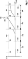
- Fig. 5 shows a time course of a Breintegralwindrate in the form of a rotation angle 511 in a coordinate system in which the abscissa time T in milliseconds and on the ordinate of the rotation angle [°] is plotted.
- the rotation angle is determined by integration of in Fig. 4 shown course of the rate of rotation over time, the rotation angle 511 is reset regularly. Instead of integration, it is also possible to accumulate discrete values of the rotation rate. Even if there is no true rate of rotation, the course of the rate of rotation due to noise can have a rash. Thus, the course of the rotation angle 511 can also indicate rotation angle values, if there is no rotation rate in real terms.
- an upper offset threshold 513 is shown.
- Fig. 5 it can be seen that the in Fig. 4 corresponding times 431, 433, 435 between the start time 321 and the stop time 323 are selected so that between adjacent times 321, 431, 433, 435, 323 time windows 541, 542, 543, 544 are formed for the integration of the rotation rate.
- the time windows 541, 542, 543, 544 may each have the same duration.
- the start time 321 starts the integration of the rotation rate.
- the rotation rate has a symmetry about the zero point oscillation curve. Accordingly, the course of the rotation angle 511 within the first time window 541 has no increase.
- the value of the rotation angle 511 is reset.
- the rotation rate has a waveform shifted from the zero point. Accordingly, the course of the rotation angle 511 within the second time window 542 has an increase.
- the course of the rotation angle 511 within the second time window 542 does not exceed the offset threshold 513.
- the value of the rotation angle 511 is reset.
- the rotation rate has a vibration course shifted from the zero point. Accordingly, the course of the rotation angle 511 within the third time window 543 has an increase. After the rate of rotation in the third time window 543 at least temporarily exceeds the upper offset and noise threshold, the course of the rotation angle 511 within the third time window 543 exceeds the offset threshold 513. This leads to an offset error detection 550. Thus, one has exceeded the predetermined tolerance lying deviation of the rotation rate signal detected. At the end of the third time window 543, at the time 435, the value of the rotation angle 511 is reset.
- the rate of rotation continues to have a shifted from the zero point waveform. Accordingly, the course of the rotation angle 511 within the fourth time window 544 has an increase.
- the integration ends with the stop time 323, which is characterized in that the in Fig. 3 shown acceleration exceeds the upper noise threshold.
- the inventive method is based on the FIGS. 3 to 5 again described the embodiment of a vehicle.
- centrifugal force F z a lateral acceleration force, the centrifugal force F z , occurs on the vehicle.
- the centrifugal force is composed of the mass of the vehicle, the speed and the radius of the curve. As long as this force F Z is less than the static friction force F R of the vehicle, the vehicle will move safely through the curve.
- the static friction arises the weight of the vehicle and the coefficient of static friction ⁇ , which depends on the two friction partners wheel-road.
- ⁇ is about 0.1.
- This lateral acceleration ay is in the range of 0.981 m / s 2 .
- the absolute rotation rate offset error of the yaw rate can be determined.
- the acceleration signal ay 311 of the vehicle transverse axis is continuously monitored for its size, as shown in FIG Fig. 3 is shown. This is necessary because accelerations of the vehicle transverse axis represent the essential variable for the possible occurrence of rotations about the vehicle vertical axis or only indicate a cornering, which also lead to small rotation rates about the vertical axis.
- the acceleration signal ay of the vehicle transverse axis is within a defined range, which corresponds to the resting value of the signal without external lateral acceleration including the permitted noise, as shown in FIG Fig. 3 is denoted by ⁇ 1 ⁇
- the yaw rate signal 411 of the yaw rate sensor included in Fig. 4 shown to be monitored for offset errors.
- no increased lateral acceleration ay is integrated over the noise of each data word of the yaw rate sensor over a fixed time interval t_integral to the angle of rotation, as shown in FIG Fig. 5 is characterized by ⁇ 2 ⁇ .
- This time window t_Integral 541, 542, 543, 544, shown in FIG Fig. 5 is set to 20ms, but could also be extended arbitrarily.
- the minimum requirement of 20ms results from the desired fault detection time, which may correspond to a request from the customers.
- each new gyro date provided will be integrated.
- the integration eliminates noise and other random signals from the yaw rate sensor.
- the angle of rotation results from the addition of the rate of rotation per signal data over the time t_integral, here 20 ms.
- a lateral acceleration ay less than or equal to a specified noise of the lateral acceleration ay including a possible safety margin means rest. So there are no external influences. This is comparable to a straight ahead.
- Each signal data ⁇ z with a maximum of 3 ° / s, which are allowed per 1 ms sampling time, is integrated on 20ms. This results in a rotation angle of 0.06 °.
- the measured lateral acceleration ay will only correspond to the known noise and allowed offset drift of the lateral acceleration sensor. In today's inertial sensors, this value will be in the range of about 0.1 m / s 2 .
- This threshold shown in Fig. 3 , however, can be freely chosen to take into account system-specific adaptations to the target application. As a rule, however, the threshold will be derived from the known noise of the lateral acceleration sensor including the offset, taking into account also its maximum values, so-called peak-to-peak values.
- the response threshold is responsible for the beginning of the offset drift measurement, ie the integration of the yaw rate of the yaw rate sensor. At the same time, however, the increase in the transverse acceleration beyond this threshold also means that the offset drift measurement has stopped, since it must now be assumed that external physical forces can produce a real yaw rate in the yaw rate sensor, as described in US Pat Figures 3 and 5 represented by ⁇ 3 ⁇ .
- the above example shows a permissible angle of rotation of ⁇ 0.06 ° over 20 ms integration. So as long as the rotation angle remains below 0.06 ° absolute, depending on the length, ie duration, the integration and the allowed offset of the sensor, there is no unacceptable offset drift. Drifting over ⁇ 3 ° / s, as in Fig. 4 represented by ⁇ 4 ⁇ , but are recognized by the integration and lead to a larger rotation angle than 0.06 ° absolute. This violation is used as a condition to indicate the impermissible deviation of the rotation rate offset to the system as shown in Fig. 5 represented by ⁇ 5 ⁇ .
- a monitoring signal which is constantly present during the transmission of the current sensor signals to the evaluation system, e.g. to a microcontroller, is integrated.
- the evaluation system e.g. to a microcontroller
- a digital accelerometer may use its SPI interface to digitally display additional information in addition to the reading.
- Fig. 6 shows a flowchart of an embodiment of the present invention. This embodiment is based on a principle of storing the integrated rotation angle in phases of rest, so where no lateral acceleration occurs.
- a step 630 it is checked whether the angle of rotation over the time window, here over 20 ms, is completely integrated.
- the rotation angle 411 is completely integrated at the times 431, 433, 435, 323. If it is determined in step 630 that the rotation angle is not completely integrated, step 630 is repeated. If, on the other hand, it is determined in step 630 that the rotation angle is completely integrated, in step 632 the angle of rotation is stored, for example in a variable x. Thus, the angle of rotation determined during the last integration performed is stored. In addition, a new integration is started. During the course of the new integration, it is again checked in step 630 whether the new rotation angle is completely integrated.
- Steps 630, 632 may again be performed as long as ay ⁇ ay_allowed.
- ay denotes the acceleration indicated by the sensor in the transverse direction and ay_ permits the response threshold as shown in FIG Fig. 3 are shown.
- Fig. 7 shows a flowchart of an embodiment of the present invention. This embodiment is based on a principle of providing an information when the threshold for the permitted rotation angle is exceeded.
- a step 740 it is checked whether the rotation angle x is above the permitted rotation angle.
- the angle of rotation x may be the angle of rotation which occurs in the in Fig. 6 embodiment shown in step 632 is stored. This makes it possible to compare the rotation angle with a threshold value after the time window of the integration has expired. Alternatively, it may also be at the angle of rotation in the Fig. 5 shown rotation angle 411, which can be continuously compared during the implementation of the integration with the threshold. If it is determined in step 740 that the rotation angle is not above the allowable rotation angle, step 740 is repeated. If, on the other hand, it is determined in step 740 that the angle of rotation lies above the permitted angle of rotation, then in step 742 information about setting a status message takes place. The status message may indicate that the rotation angle exceeds the permitted rotation angle, and thus there is a deviation of the rotation rate signal that is above the tolerated or known deviation.
- Step 740 may be repeated continuously so that continuous monitoring of variable x is performed.
- the basis of the FIGS. 3 to 5 described measurement of the rotational rate offset continuously from the sensor or even from the subsequent evaluation done as long as only the lateral acceleration of the vehicle, measured over the integrated high-resolution side acceleration sensor below the trigger threshold of, for example, ⁇ 0.1m / s 2 .
- the calculated rotation angle is saved.
- the following results from the continuous measurements, here every 20 ms, are also stored continuously by overwriting the previously calculated rotation angle.
- the evaluation unit can return the transmitted rotation angle by knowing the integration time t_integral at any time in the absolute rotation rate offset in Recalculate calm. This is done by simply differentiating the angle of rotation over time t_integral.
- the monitoring according to the invention can also be applied to a roll rate sensor.
- These inertial sensors also have a highly sensitive lateral ay and vertical az acceleration element. When vehicle turns about the longitudinal axis, a roll corresponds to a rollover, always occur on vertical and lateral accelerations. The monitoring of both accelerations on exceeding of the permitted noise can be used to cancel the offset drift measurement of the roll rate signal.
- the method according to the invention is therefore applicable to all inertial sensors, that is to say sensors which have at least one yaw rate channel and an acceleration channel in the direction of action relative to the axis of rotation in a housing, for example a ⁇ Z twist rate element and an ay acceleration element.
- the internal acceleration channel must be sensitive enough to detect accelerations leading to yaw rates in the yaw rate sensor above its own noise.
- all ESP central acceleration sensors are referred to as "low gx, y”.
- the measuring range is usually in the range up to ⁇ 50m / s 2 , whereby the resolution is at least 0.002m / s 2 .
- External acceleration sensors can also be used. This means that intertial sensors are not absolutely necessary for the application according to the invention.
- the signal processing and offset determination does not necessarily have to be in the same sensor housing, for example on an ASIC, and could also be taken over by an external arithmetic unit. Typical for this are also analogue sensors in which the measuring signal is transmitted analogously to an external microcontroller and there the further processing takes place.
- the approach according to the invention can be used with inertial sensors.
- Such sensors may include an integrated microcontroller that may be used to monitor the sensor signals.
- the advantage of such a microcontroller lies in a flexible programming which can be accessed directly on the measurement data of the sensor in the sensor itself.
- the implementation of the offset drift monitoring according to the invention can thus Software programming is not necessary and does not have to be taken into account in the ASIC design, which also results in a cost reduction.
- the parameterization can be carried out flexibly during the development of the individual sample phases.
Landscapes
- Engineering & Computer Science (AREA)
- Radar, Positioning & Navigation (AREA)
- Remote Sensing (AREA)
- Physics & Mathematics (AREA)
- General Physics & Mathematics (AREA)
- Theoretical Computer Science (AREA)
- Manufacturing & Machinery (AREA)
- Automation & Control Theory (AREA)
- Data Mining & Analysis (AREA)
- Software Systems (AREA)
- General Engineering & Computer Science (AREA)
- Mathematical Physics (AREA)
- Databases & Information Systems (AREA)
- Gyroscopes (AREA)
Description
Die vorliegende Erfindung bezieht sich auf ein Verfahren zur Erkennung einer Abweichung eines Drehratensignals eines Drehratensensors, auf ein entsprechendes Steuergerät sowie auf ein entsprechendes Computerprogrammprodukt.The present invention relates to a method for detecting a deviation of a rotation rate signal of a rotation rate sensor, to a corresponding control device and to a corresponding computer program product.
Für die aktive und passive Sicherheit eingesetzten Inertialsensoren bestehen aus einem einkanaligen Drehratensensor und einem zweikanaligen Beschleunigungssensor in einem Gehäuse. Es werden sehr hohe Anforderungen an die Offsetstabilität der Inertialsensoren gestellt.Inertial sensors used for active and passive safety consist of a single-channel rotation rate sensor and a dual-channel acceleration sensor in one housing. Very high demands are placed on the offset stability of the inertial sensors.
Die
Aus der
Aus der
Aus der
Vor diesem Hintergrund wird mit der vorliegenden Erfindung ein Verfahren zur Erkennung einer Abweichung eines Drehratensignals eines Drehratensensors, weiterhin eine Vorrichtung, die dieses Verfahren verwendet sowie schließlich ein entsprechendes Computerprogrammprodukt gemäß den unabhängigen Patentansprüchen vorgestellt. Vorteilhafte Ausgestaltungen ergeben sich aus den jeweiligen Unteransprüchen und der nachfolgenden Beschreibung.Against this background, the present invention provides a method for detecting a deviation of a rotation rate signal of a rotation rate sensor, furthermore a device which uses this method, and finally a corresponding computer program product according to the independent patent claims. Advantageous embodiments emerge from the respective subclaims and the following description.
Die Erfindung basiert auf der Erkenntnis, dass ein absoluter Drehratenoffsetfehler, hervorgerufen durch unzulässige Driften oder Fehler im Sensor, in Ruhelage selbstständig von dem Sensor ermittel werden kann. Es wird kein zusätzlicher Drehratensensor für die Überwachung benötigt. Dabei interessiert nur der Fehler, der über einen spezifizierten, bekannten Fehler hinaus geht. Überschreitungen können so dem System angezeigt bzw. als absolute Größe zur Verfügung gestellt werden. Damit kann eine auf einem Signal des Sensors basierende relevante Funktion auf den Fehler reagieren, indem beispielsweise der Sicherheitsbereich zum Auslösen der Funktion vergrößert wird. Im "Normalbetrieb" muss nur mit dem reinen spezifizierten, also bekannten Fehler sicherer Betrieb gewährleistet werden. Die Güte oder Performance der Funktion kann also so hoch wie möglich gewählt werden, da über den spezifizierten Bereich hinaus unbekannte Fehler im Offset erkannt werden.The invention is based on the finding that an absolute rotational offset error, caused by impermissible drifts or errors in the sensor, can be determined independently by the sensor in the rest position. No additional rotation rate sensor is required for monitoring. Only the error that goes beyond a specified, known error is of interest. Exceeds can be displayed to the system or made available as an absolute size. Thus, a relevant function based on a signal from the sensor can respond to the error by, for example, increasing the safety margin for triggering the function. In "normal operation", safe operation must be ensured only with the purely specified, that is known error. The quality or performance of the function can therefore be selected as high as possible, since unknown errors in the offset are detected beyond the specified range.
Mittels des erfindungsgemäßen Verfahrens wird eine selbstständige Erkennung von Offsetsprüngen und Driften des Drehratensignals, beispielsweise in einem Inertialsensor mit einem Drehratensensor und einem Beschleunigungssensor ermöglicht. Für das Bestimmen des tatsächlichen Ruheoffsets des Sensors muss sichergestellt sein, dass keine externen physikalischen Kräfte am Fahrzeug eine tatsächliche Drehrate im Sensor erzeugen. Diese tatsächlich erzeugte wahre Drehrate könnte sonst als Fehldrehrate aus der Ablage zum erlaubten Ruhewert interpretiert werden. Daher werden die ebenfalls im Inertialsensor vorhandenen Signale der hochauflösenden Beschleunigungssensoren erfindungsgemäß genutzt. Anstelle von einem Inertialsensor können die Signale auch von anderen geeigneten Sensoren bereitgestellt werden.By means of the method according to the invention, an independent detection of offsets jumps and drifts of the rotation rate signal, for example in an inertial sensor with a yaw rate sensor and an acceleration sensor, is made possible. For determining the actual resting offset of the sensor, it must be ensured that no external physical forces on the vehicle generate an actual rate of turn in the sensor. This actually generated true rate of rotation could otherwise be interpreted as a misguided rate from the storage to the permitted rest value. Therefore, the signals of the high-resolution acceleration sensors, which are also present in the inertial sensor, are used according to the invention. Instead of an inertial sensor, the signals may also be provided by other suitable sensors.
Die Anforderungen, die an die Offsetstabilität von Inertialsensoren gestellt werden, umfassen beispielsweise, dass das Drehratensignal ohne Einfluss externer physikalischer Kräfte, also in Ruhelage, nur ein Ausgangssignal von 0°/s am Sensorausgang bereitstellen darf. Da jedes Messsystem Fehler aufweist, ist dieses Signal mit einer Toleranz spezifiziert, die den gesamten Betriebsbereich sowie die Lebensdauer abdeckt. Heutige Kundenanforderungen erlauben dem Drehratensignal eine maximale Abweichung vom tatsächlich gemessenen Messwert von ±3°/s. Auf das obige Beispiel der Ruhelage bezogen, darf das am Sensorausgang bereitgestellte Drehratensignal also einen Wert zwischen -3°/s und +3°/s haben, obwohl die tatsächliche Drehrate in Ruhe 0°/s beträgt.The requirements placed on the offset stability of inertial sensors include, for example, that the yaw rate signal can only provide an output signal of 0 ° / s at the sensor output without the influence of external physical forces, ie in the rest position. Since every measuring system has errors, this signal is specified with a tolerance that covers the entire operating range as well as the service life. Today's customer requirements allow the rotation rate signal to deviate by a maximum of ± 3 ° / s from the actually measured value. Based on the above example of the rest position, the yaw rate signal provided at the sensor output may therefore have a value between -3 ° / s and + 3 ° / s, although the actual rate of rotation at rest is 0 ° / s.
In Applikationen wie ESP, aktive Lenkung oder auch Airbag ist der Offsetfehler der Inertialsensoren eine essentielle Größe, die die Güte der Funktion bestimmt. Die Fahrzeugfunktion muss daher robust genug sein, Offsetfehler, also Abweichungen vom tatsächlich anliegenden Signal, zu kompensieren. Dabei muss berücksichtigt werden, dass nicht allein der erlaubte Offsetfehler von hier ±3°/s, sondern vielmehr auch größere Abweichungen des Offset im Betrieb aufgrund unzulässiger Driften, z.B. durch ein Verlassen des spezifizierten Betriebsbereiches oder hervorgerufen durch Fehler, berücksichtigt werden. Diese Kompensation ist immer ein Kompromiss zwischen Güte und Robustheit. Das heißt, der bekannte systematische Fehler muss von der Funktion durch Bereitstellen eines Sicherheitsabstandes zu dem Funktionseingreifpunkt, also der Aktivierung, kompensiert werden oder bedingt eine ungenauere Antwort des Systems auf das Messsignal, wodurch sich ein Verlust an Güte ergibt.In applications such as ESP, active steering or airbag, the offset error of the inertial sensors is an essential factor that determines the quality of the function. The vehicle function must therefore be robust enough to compensate offset errors, ie deviations from the actually applied signal. It must be taken into account that not only the allowed offset error of ± 3 ° / s here, but also larger deviations of the offset during operation due to impermissible drifts, e.g. by leaving the specified operating range or caused by errors. This compensation is always a compromise between quality and robustness. That is, the known systematic error must be compensated by the function by providing a safe distance to the function, that is, the activation, or causes a less accurate response of the system to the measurement signal, resulting in a loss of quality.
Da es auch Funktonen im Kraftfahrzeug gibt, die eine sehr hohe Güte der Messsignale benötigen, z.B. die aktive Lenkung, ist eine Ungenauigkeit in der Antwort der Funktion nicht mehr vertretbar. Erfindungsgemäß ist es damit nicht mehr erforderlich, dort nötige Sensoren mindestens doppelt, also redundant zu verbauen, um durch Vorliegen mehrerer gleicher Messsignale die Güte dieser zu bestimmen, indem sie gegenseitig verglichen werden. Durch einen Verzicht auf die mehrfache Verwendung von gleichen Sensoren in einem Steuergerät kann ein Anstieg der Entwicklungs- und Produktionskosten vermieden werden.Since there are also functions in the motor vehicle which require a very high quality of the measuring signals, e.g. the active steering, an inaccuracy in the response of the function is no longer justifiable. According to the invention, it is thus no longer necessary to install sensors which are necessary there at least twice, that is to say redundantly, in order to determine the quality of these by the presence of a plurality of identical measuring signals by comparing them with one another. By eliminating the multiple use of the same sensors in a controller, an increase in development and production costs can be avoided.
Die vorliegende Erfindung schafft ein Verfahren zur Erkennung einer Abweichung eines Drehratensignals eines Sensors eines Fahrzeugs, das die folgenden Schritte umfasst: Empfangen einer Information über eine Linearbeschleunigung des Fahrzeugs über eine erste Schnittstelle; Empfangen des Drehratensignals über eine zweite Schnittstelle, wobei das Drehratensignal eine Drehgeschwindigkeit des Fahrzeugs repräsentiert; und Analysieren des Drehratensignals, wenn die Linearbeschleunigung kleiner als ein erster Schwellwert ist, um die Abweichung des Drehratensignals zu erkennen.The present invention provides a method of detecting a deviation of a yaw rate signal of a sensor of a vehicle, comprising the steps of: receiving information about a linear acceleration of the vehicle via a first interface; Receiving the yaw rate signal via a second interface, the yaw rate signal representing a rotational speed of the vehicle; and analyzing the yaw rate signal if the linear acceleration is less than a first threshold to detect the deviation of the yaw rate signal.
Bei dem Fahrzeug kann es sich um ein Kraftfahrzeug handeln. Die Information über die Linearbeschleunigung und das Drehratensignal können von einem oder mehreren Sensoren, beispielsweise von Beschleunigungssensoren oder von einem Inertialsensor, bereitgestellt werden. Sind der oder die Sensoren in dem Fahrzeug angeordnet, so können die Linearbeschleunigung und die Drehrate des Fahrzeugs ermittelt werden. Die Linearbeschleunigung kann eine Querbeschleunigung oder eine Längsbeschleunigung des Fahrzeugs darstellen. Die Drehrate kann eine Drehgeschwindigkeit des Fahrzeugs, beispielsweise um eine Fahrzeughochachse, Fahrzeuglängsachse oder Fahrzeugquerachse, charakterisieren. Die Abweichung des Drehratensignals kann einen Messfehler des Drehratensignals repräsentieren, also einen Unterschied zwischen einem von dem Drehratensignal angezeigten Drehratenwert und einem tatsächlich vorliegenden Drehratenwert. Die Abweichung kann aus einem Offsetfehler des Sensors resultieren, der beispielsweise durch unzulässige Driften oder durch Sensorfehler hervorgerufen werden kann. Insbesondere kann eine Abweichung erkannt werden, die eine zulässige, bekannte oder tolerierbare Abweichung des Drehratensignals überschreitet. Je nachdem, ob das Verfahren durch einen Sensor oder durch eine Auswertevorrichtung umgesetzt wird, kann es sich bei der ersten und der zweiten Schnittstelle um interne Sensorschnittstellen oder um Schnittstellen zu einem oder mehreren Sensoren handeln. Die Information über die Linearbeschleunigung kann zeitlich fortlaufend der Linearbeschleunigung entsprechende Messwerte umfassen. Somit kann die Information über eine Linearbeschleunigung einen zeitlichen Verlauf der Linearbeschleunigung bereitstellen. Entsprechend dazu kann das Drehratensignal zeitlich fortlaufend der Drehrate entsprechende Messwerte umfassen. Somit kann das Drehratensignal einen zeitlichen Verlauf der Drehrate bereitstellen. Das Analysieren des Drehratensignals kann erfolgen, wenn die Linearbeschleunigung betragsmäßig kleiner als der erste Schwellwert ist. Die Information über die Linearbeschleunigung kann einen Ruhefehler aufweisen. Der Ruhefehler kann zu einem angezeigten Wert für eine Linearbeschleunigung führen, obwohl sich der Sensor in Ruhe befindet, als tatsächlich keine Linearbeschleunigung vorliegt. Der erste Schwellwert kann eine erlaubte Toleranzgrenze für den Ruhefehler definieren. Das Analysieren des Drehratensignals kann ein Auswerten aufeinanderfolgender Werte des Drehratensignals umfassen. Dabei können die aufeinanderfolgenden Werte des Drehratensignals zusammengefasst und anschließend mit einem geeigneten Schwellwert verglichen werden. Je nach Ausführungsform kann ein Erreichen, Überschreiten oder Unterschreiten des Schwellwertes eine Abweichung des Drehratensignals anzeigen. Wird die Abweichung des Drehratensignals erkannt, so kann eine entsprechende Information bereitgestellt werden. Die Information kann einen Hinweis darauf enthalten, dass eine Abweichung vorliegt. Zusätzlich kann die Information eine Größe der Abweichung anzeigen. Die Größe der Abweichung kann einen aktuellen Sensorfehler charakterisieren, der bei einer Weiterverarbeitung der Sensordaten berücksichtigt werden kann. Alternativ kann eine Weiterverarbeitung der Sensordaten verhindert werden, wenn die Erkannte Abweichung zu groß ist.The vehicle may be a motor vehicle. The information about the linear acceleration and the rotation rate signal can be from one or more sensors, for example, from acceleration sensors or from a Inertialsensor be provided. If the sensor or sensors are arranged in the vehicle, then the linear acceleration and the rate of rotation of the vehicle can be determined. The linear acceleration may represent a lateral acceleration or a longitudinal acceleration of the vehicle. The rotation rate may characterize a rotational speed of the vehicle, for example about a vehicle vertical axis, vehicle longitudinal axis or vehicle transverse axis. The deviation of the rotation rate signal can represent a measurement error of the rotation rate signal, that is to say a difference between a rotation rate value displayed by the rotation rate signal and a rotation rate value actually present. The deviation can result from an offset error of the sensor, which can be caused for example by impermissible drifts or by sensor errors. In particular, a deviation can be detected which exceeds a permissible, known or tolerable deviation of the yaw rate signal. Depending on whether the method is implemented by a sensor or by an evaluation device, the first and the second interface may be internal sensor interfaces or interfaces to one or more sensors. The information about the linear acceleration may comprise temporally continuous measured values corresponding to the linear acceleration. Thus, the information about a linear acceleration can provide a time course of the linear acceleration. Correspondingly, the rotation rate signal can comprise corresponding measurement values in chronological order of the rotation rate. Thus, the rotation rate signal can provide a time course of the rotation rate. The analysis of the rotation rate signal can take place if the linear acceleration is smaller in magnitude than the first threshold value. The information about the linear acceleration may have a rest error. The quiescent error can result in a displayed value for linear acceleration, even though the sensor is at rest when there is actually no linear acceleration. The first threshold may define an allowable tolerance limit for the sleep error. Analyzing the yaw rate signal may include evaluating successive values of the yaw rate signal. In this case, the successive values of the yaw rate signal can be combined and then compared with a suitable threshold value. Depending on the embodiment, reaching, exceeding or undershooting the threshold value may indicate a deviation of the yaw rate signal. If the deviation of the yaw rate signal detected, then a corresponding information can be provided. The information can contain an indication that there is a deviation. In addition, the information may indicate a size of the deviation. The magnitude of the deviation may characterize a current sensor error that may be taken into account in further processing of the sensor data. Alternatively, further processing of the sensor data can be prevented if the detected deviation is too large.
Das erfindungsgemäße Verfahren kann einen Schritt des Vergleichens der Information über die Linearbeschleunigung mit dem ersten Schwellwert umfassen. Mittels des Vergleichens kann bestimmt werden, ob die Linearbeschleunigung kleiner als der erste Schwellwert ist. Dabei kann ein Betrag der Linearbeschleunigung mit dem ersten Schwellwert verglichen werden. Alternativ können für unterschiedliche Vorzeichen der Linearbeschleunigung unterschiedliche erste Schwellwerte vorgesehen sein, die sich betragsmäßig unterscheiden oder nicht unterscheiden können. Auch kann ein aufbereiteter Wert der Linearbeschleunigung mit dem ersten Schwellwert verglichen werden. Eine entsprechende Aufbereitung kann eine Verstärkung oder Filterung der gemessenen Linearbeschleunigung umfassen. Dabei kann aus dem aufbereiteten Wert nach wie vor auf einen absoluten Wert der Linearbeschleunigung geschlossen werden und nicht nur auf eine Veränderung der Linearbeschleunigung, wie es beispielsweise bei einer Ableitung eines zeitlichen Verlaufs der Linearbeschleunigung der Fall wäre. Ergibt das Vergleichsergebnis, das die Linearbeschleunigung kleiner als der erste Schwellwert ist, so kann davon ausgegangen werden, dass entweder keine oder nur eine vernachlässigbar kleine Linearbeschleunigung und somit auch keine oder nur eine vernachlässigbar kleine Drehrate vorliegt. In diesem Fall kann das Analysieren des Drehratensignals begonnen oder weitergeführt werden. Für den Fall, dass aufgrund des Vergleichs festgestellt wird, dass eine nicht vernachlässigbare Linearbeschleunigung vorliegt, so kann das Analysieren des Drehratensignals beendet oder erst gar nicht begonnen werden.The method according to the invention may comprise a step of comparing the information about the linear acceleration with the first threshold value. By means of the comparison it can be determined whether the linear acceleration is smaller than the first threshold value. In this case, an amount of the linear acceleration can be compared with the first threshold value. Alternatively, different first threshold values can be provided for different signs of the linear acceleration, which differ in magnitude or can not differentiate. Also, a conditioned value of the linear acceleration can be compared with the first threshold value. Corresponding conditioning may include amplification or filtering of the measured linear acceleration. In this case, it is still possible to deduce an absolute value of the linear acceleration from the processed value and not just a change in the linear acceleration, as would be the case, for example, in the derivation of a time profile of the linear acceleration. If the result of the comparison shows that the linear acceleration is less than the first threshold value, then it can be assumed that there is either no or only a negligible linear acceleration and thus also no or only a negligibly small rotation rate. In this case, analyzing the yaw rate signal can be started or continued. In the event that it is determined on the basis of the comparison that there is a non-negligible linear acceleration, the analysis of the yaw rate signal can be terminated or not even begun.
Der Schritt des Analysierens kann ein Aufsummieren des Drehratensignals über eine Zeitspanne umfassen. Durch das Aufsummieren kann ein Drehratensummensignal erhalten werden. Die Abweichung des Drehratensignals kann durch ein Vergleichen des Drehratensummensignals mit einem zweiten Schwellwert erkannt werden. Beim Aufsummieren können zeitlich aufeinanderfolgende vorzeichenbehaftete diskrete Werte der Drehrate aufaddiert werden. Auch kann beim Aufsummieren ein Integrieren des Drehratensignals über die Zeit durchgeführt werden. Das Drehratensummensignal kann somit einem Drehwinkel entsprechen, der innerhalb der Zeitspanne tatsächlich besteht oder durch die Abweichung des Drehratensignals vorgetäuscht wird. Sofern die Linearbeschleunigung kleiner als der erste Schwellwert ist, kann davon ausgegangen werden, dass keine Drehung vorliegt und das Drehratensummensignal somit aus der Abweichung des Drehratensignals resultiert. Die Zeitspanne kann fest vorgegeben sein. Die Abweichung kann als erkannt gelten, wenn das Drehratensummensignal innerhalb der Zeitspanne oder am Ende der Zeitspanne den zweiten Schwellwert erreicht oder passiert.The step of analyzing may comprise summing the yaw rate signal over a period of time. By summing up, a rotation rate sum signal can be obtained. The deviation of the rotation rate signal can be detected by comparing the rotation rate sum signal with a second threshold value. During summation, time-sequential signed discrete values of the rotation rate can be added up. Also can at Summing up integrating the yaw rate signal over time. The rotation rate sum signal can thus correspond to a rotation angle which actually exists within the time period or is simulated by the deviation of the rotation rate signal. If the linear acceleration is smaller than the first threshold, it can be assumed that there is no rotation and thus the yaw-rate signal results from the deviation of the yaw-rate signal. The time span can be fixed. The deviation may be considered detected when the rotation rate sum signal reaches or passes the second threshold within the time period or at the end of the time period.
Gemäß einer Ausführungsform kann die Abweichung des Drehratensignals erkannt werden, wenn das Drehratensummensignal innerhalb der Zeitspanne den zweiten Schwellwert überschreitet. Die Zeitspanne kann kleiner als 200ms sein. Beispielsweise kann die Zeitspanne zwischen 20ms und 40ms dauern. Nach Ablauf einer ersten Zeitspanne kann das Drehratensignal erneut analysiert werden. Dazu kann das Drehratensummensignal zurückgesetzt und mit einem erneuten Aufsummieren des Drehratensignals begonnen werden.According to one embodiment, the deviation of the yaw rate signal can be detected when the yaw rate signal exceeds the second threshold within the time period. The time span can be less than 200ms. For example, the time span can be between 20ms and 40ms. After a first period of time, the rotation rate signal can be analyzed again. For this purpose, the rotation rate sum signal can be reset and started with a new summation of the rotation rate signal.
Der erste Schwellwert kann kleiner oder gleich einem Grenzwert eines zulässigen Rauschanteils der Information über die Linearbeschleunigung sein. Auf diese Weise kann auf einfache Weise bestimmt werden, ob eine tatsächliche Linearbeschleunigung vorliegt, die ein Erkennen der Abweichung des Drehratensignals verhindern würde.The first threshold may be less than or equal to a threshold of allowable noise of the linear acceleration information. In this way it can be determined in a simple manner whether an actual linear acceleration is present, which would prevent detection of the deviation of the yaw rate signal.
Entsprechend dazu kann der zweite Schwellwert einem Wert entsprechen, der sich durch ein Aufsummieren einer zulässigen Abweichung des Drehratensignals über die Zeitspanne ergibt. Somit kann der zweite Schwellwert einem über die Zeitspanne aufsummierten Wert der zulässigen Abweichung des Drehratensignals entsprechen. Auch kann der zweite Schwellwert einem Wert entsprechen, der geringfügig größer als der Wert ist, der sich durch ein Aufsummieren der zulässigen Abweichung des Drehratensignals über die Zeitspanne ergibt. Die zulässige Abweichung kann einem bekannten spezifizierten Fehler des Drehratensignals entsprechen. Führt das Aufsummieren des Drehratensignals zu einem Erreichen oder Überschreiten des zweiten Schwellwertes, obwohl über die Linearbeschleunigung festgestellt wird, das keine tatsächliche Drehrate vorliegt, so bedeutet dies, dass die Abweichung des Drehratensignals größer als die zulässige Abweichung ist.Correspondingly, the second threshold value may correspond to a value resulting from adding up an allowable deviation of the rotation rate signal over the time period. Thus, the second threshold value can correspond to a value of the permissible deviation of the yaw rate signal added over the time period. Also, the second threshold may correspond to a value slightly greater than the value obtained by summing the allowable deviation of the yaw rate signal over the time period. The allowable deviation may correspond to a known specified error of the yaw rate signal. If the summation of the yaw rate signal leads to reaching or exceeding the second threshold value, although it is determined via the linear acceleration that there is no actual yaw rate, then this means that the deviation of the yaw rate signal is greater than the permissible deviation.
Gemäß einer Ausführungsform kann das erfindungsgemäße Verfahren einen Schritt des Bereitstellens eines Wertes des Drehratensummensignals zum Ende der Zeitspanne umfassen. Das Drehratensummensignal kann vor einem Rücksetzten des Drehratensummensignals für eine erneute Analyse der Drehrate an eine Auswerteeinrichtung oder an eine Speichereinrichtung bereitgestellt werden. Das Drehratensummensignal gibt einen Hinweis auf eine aktuell vorliegende Abweichung des Drehratensignals und kann bei einer Weiterverarbeitung des Drehratensignals berücksichtigt werden. Beispielsweise kann aus dem Drehratensummensignal ein Korrekturwert zur Korrektur eines zur Weiterverarbeitung vorgesehenen Drehratensignals eingesetzt werden.According to one embodiment, the method according to the invention may comprise a step of providing a value of the rotation rate sum signal at the end of the time period. The yaw rate signal may be provided to an evaluation device or to a memory device prior to resetting the yaw rate signal for re-analysis of the yaw rate. The rotation rate sum signal gives an indication of a currently existing deviation of the rotation rate signal and can be taken into account in a further processing of the rotation rate signal. For example, a correction value for the correction of a rotation rate signal provided for further processing can be used from the rotation rate sum signal.
Die Linearbeschleunigung kann eine Querbeschleunigung oder Längsbeschleunigung des Fahrzeugs und die Drehrate eine Drehgeschwindigkeit des Fahrzeugs um eine Fahrzeughochachse, Fahrzeuglängsachse oder Fahrzeugquerachse repräsentieren. Somit kann das erfindungsgemäße Verfahren vorteilhaft zur Absicherung der Gierrate und/oder der Rollrate und/oder der Pitchrate eingesetzt werden.The linear acceleration may represent a lateral acceleration or longitudinal acceleration of the vehicle and the rate of rotation a rotational speed of the vehicle about a vehicle vertical axis, vehicle longitudinal axis or vehicle transverse axis. Thus, the method according to the invention can advantageously be used to secure the yaw rate and / or the roll rate and / or the pitch rate.
Die vorliegende Erfindung schafft ferner eine Vorrichtung, die ausgebildet ist, um die Schritte des erfindungsgemäßen Verfahrens in entsprechenden Einrichtungen durchzuführen bzw. umzusetzen. Auch durch diese Ausführungsvariante der Erfindung in Form einer Vorrichtung kann die der Erfindung zugrunde liegende Aufgabe schnell und effizient gelöst werden. Bei der Vorrichtung kann es sich um einen Sensor, eine Auswertevorrichtung oder um ein Steuergerät handeln.The present invention further provides an apparatus adapted to perform the steps of the method according to the invention in corresponding devices. Also by this embodiment of the invention in the form of a device, the object underlying the invention can be solved quickly and efficiently. The device may be a sensor, an evaluation device or a control device.
Unter einer Vorrichtung kann vorliegend ein elektrisches Gerät verstanden werden, das Sensorsignale verarbeitet und in Abhängigkeit davon Steuersignale ausgibt. Die Vorrichtung kann eine Schnittstelle aufweisen, die hard- und/oder softwaremäßig ausgebildet sein kann. Bei einer hardwaremäßigen Ausbildung können die Schnittstellen beispielsweise Teil eines sogenannten System-ASICs sein, der verschiedenste Funktionen der Vorrichtung beinhaltet. Es ist jedoch auch möglich, dass die Schnittstellen eigene, integrierte Schaltkreise sind oder zumindest teilweise aus diskreten Bauelementen bestehen. Bei einer softwaremäßigen Ausbildung können die Schnittstellen Softwaremodule sein, die beispielsweise auf einem Mikrocontroller neben anderen Softwaremodulen vorhanden sind.In the present case, a device can be understood as meaning an electrical device which processes sensor signals and outputs control signals in dependence thereon. The device may have an interface, which may be formed in hardware and / or software. In the case of a hardware-based embodiment, the interfaces can be part of a so-called system ASIC, for example, which contains a wide variety of functions of the device. However, it is also possible that the interfaces are their own integrated circuits or at least partially consist of discrete components. In a software-based Training, the interfaces may be software modules that are present for example on a microcontroller in addition to other software modules.
Von Vorteil ist auch ein Computerprogrammprodukt mit Programmcode, der auf einem maschinenlesbaren Träger wie einem Halbleiterspeicher, einem Festplattenspeicher oder einem optischen Speicher gespeichert ist und zur Durchführung des Verfahrens nach einer der vorstehend beschriebenen Ausführungsformen verwendet wird, wenn das Programm auf einem Steuergerät ausgeführt wird.Also of advantage is a computer program product with program code which is stored on a machine-readable carrier such as a semiconductor memory, a hard disk memory or an optical memory and is used to carry out the method according to one of the embodiments described above, when the program is executed on a control unit.
Die Erfindung wird nachstehend anhand der beigefügten Zeichnungen beispielhaft näher erläutert. Es zeigen:
- Fig. 1
- ein schematische Darstellung eines Fahrzeugs;
- Fig. 2
- ein Ablaufdiagramm eines erfindungsgemäßen Verfahrens;
- Fig. 3
- eine Darstellung eines Beschleunigungssignals;
- Fig. 4
- eine Darstellung eines Drehratensignals;
- Fig. 5
- eine Darstellung einer Analyse des Drehratensignals;
- Fig. 6
- ein Ablaufdiagramm eines Ausführungsbeispiels der vorliegenden Erfindung; und
- Fig. 7
- ein Ablaufdiagramm eines weiteren Ausführungsbeispiels der vorliegenden Erfindung.
- Fig. 1
- a schematic representation of a vehicle;
- Fig. 2
- a flow diagram of a method according to the invention;
- Fig. 3
- a representation of an acceleration signal;
- Fig. 4
- a representation of a rotation rate signal;
- Fig. 5
- a representation of an analysis of the rotation rate signal;
- Fig. 6
- a flowchart of an embodiment of the present invention; and
- Fig. 7
- a flowchart of another embodiment of the present invention.
In der nachfolgenden Beschreibung bevorzugter Ausführungsbeispiele der vorliegenden Erfindung werden für die in den verschiedenen Figuren dargestellten und ähnlich wirkenden Elemente gleiche oder ähnliche Bezugszeichen verwendet, wobei auf eine wiederholte Beschreibung dieser Elemente verzichtet wird.In the following description of preferred embodiments of the present invention, the same or similar reference numerals are used for the elements shown in the various figures and similarly acting, wherein a repeated description of these elements is omitted.
Gezeigt ist ein Fahrzeug 100, in dem ein Inertialsensor 102 angeordnet ist. Der Inertialsensor 102 ist ausgebildet, um Linearbeschleunigungen des Fahrzeugs in der Fahrzeuglängsachse x und der Fahrzeugquerachse y und eine Drehrate ωZ des Fahrzeugs um die Fahrzeughochachse z zu erfassen und entsprechende Informationen oder Signale an eine Auswerteeinrichtung 104 bereitzustellen. Die Auswerteeinrichtung 104 kann Teil des Inertialsensor 102 sein oder als separate Einrichtung ausgeführt sein, die über eine entsprechende Schnittstelle mit dem Inertialsensor 102 verbunden ist.Shown is a
Anhand der
In einem Zeitbereich bis zu einem Startzeitpunkt 321 weist der Verlauf der Linearbeschleunigung 311 starke Schwingungen mit einer Amplitude auf, die die Rauschschwellen 313, 315 überschreitet. Ab dem Startzeitpunkt 321 und bis zu einem Stoppzeitpunkt 323 weist der Verlauf der Linearbeschleunigung 311 Schwingungen auf, die innerhalb des durch die Rauschschwellen 313, 315 begrenzten Bereichs verlaufen. Die Schwingungen zwischen den Zeitpunkten 321, 323 können durch Rauschen hervorgerufen sein. Das heißt es wird der Verlauf der Linearbeschleunigung 311 zeigt eine Linearbeschleunigung an, obwohl real keine Linearbeschleunigung vorliegt. Zum Stoppzeitpunkt 323 überschreitet der Verlauf der Linearbeschleunigung 311 die obere Rauschschwelle 313. Dies kann dadurch verursacht sein, das eine tatsächliche Linearbeschleunigung vorliegt.In a time range up to a
Zwischen dem Startzeitpunkt 321 und dem Stoppzeitpunkt 323, die den entsprechenden Zeitpunkten aus
Aus
Vor dem Startzeitpunkt 321 findet keine Analyse der Drehrate statt. Die Analyse beginnt mit dem Startzeitpunkt 321. Dementsprechend beginnt mit dem Startzeitpunkt 321 die Integration der Drehrate. Innerhalb des ersten Zeitfensters 541 weist die Drehrate einen um den Nullpunkt symmetrischen Schwingungsverlauf auf. Dementsprechend weist der Verlauf des Drehwinkels 511 innerhalb des ersten Zeitfensters 541 keinen Anstieg auf. Am Ende des ersten Zeitfensters 541, zum Zeitpunkt 431 wird der Wert des Drehwinkels 511 wieder zurückgesetzt. Innerhalb der zweiten Hälfte des zweiten Zeitfensters 542 weist die Drehrate einen vom Nullpunkt verschobenen Schwingungsverlauf auf. Dementsprechend weist der Verlauf des Drehwinkels 511 innerhalb des zweiten Zeitfensters 542 einen Anstieg auf. Nachdem die Drehrate im zweiten Zeitfenster 542 innerhalb der Offset - und Rauschschwellen verläuft, übersteigt der Verlauf des Drehwinkels 511 innerhalb des zweiten Zeitfensters 542 nicht die Offsetschwelle 513. Am Ende des zweiten Zeitfensters 542, zum Zeitpunkt 433 wird der Wert des Drehwinkels 511 wieder zurückgesetzt.Before the
Innerhalb des dritten Zeitfensters 543 weist die Drehrate einen vom Nullpunkt verschobenen Schwingungsverlauf auf. Dementsprechend weist der Verlauf des Drehwinkels 511 innerhalb des dritten Zeitfensters 543 einen Anstieg auf. Nachdem die Drehrate im dritten Zeitfenster 543 zumindest zeitweise die obere Offset-und Rauschschwelle überschreitet, übersteigt der Verlauf des Drehwinkels 511 innerhalb des dritten Zeitfensters 543 die Offsetschwelle 513. Dies führt zu einer Offset-Fehler-Erkennung 550. Somit wurde eine über der vorgegebenen Toleranz liegende Abweichung des Drehratensignals erkannt. Am Ende des dritten Zeitfensters 543, zum Zeitpunkt 435 wird der Wert des Drehwinkels 511 wieder zurückgesetzt.Within the
Innerhalb des vierten Zeitfensters 544 weist die Drehrate weiterhin einen vom Nullpunkt verschobenen Schwingungsverlauf auf. Dementsprechend weist der Verlauf des Drehwinkels 511 innerhalb des vierten Zeitfensters 544 einen Anstieg auf. Die Integration endet mit dem Stoppzeitpunkt 323, der dadurch gekennzeichnet ist, dass die in
Im Folgenden wird das erfindungsgemäße Verfahren anhand der
Bei jeder Kurvenfahrt tritt eine Seitenbeschleunigungskraft, die Zentrifugalkraft FZ, am Fahrzeug auf. Die Zentrifugalkraft setzt sich aus der Masse des Fahrzeuges, der Geschwindigkeit und dem Radius der Kurve zusammen. Solange diese Kraft FZ kleiner als die Haftreibungskraft FR des Fahrzeuges ist, wird sich das Fahrzeug sicher durch die Kurve bewegen. Die Haftreibungskraft ergibt sich aus der Gewichtskraft des Fahrzeugs und der Haftreibungszahl µ, die von den beiden Reibpartnern Rad-Straße abhängt.At each cornering, a lateral acceleration force, the centrifugal force F z , occurs on the vehicle. The centrifugal force is composed of the mass of the vehicle, the speed and the radius of the curve. As long as this force F Z is less than the static friction force F R of the vehicle, the vehicle will move safely through the curve. The static friction arises the weight of the vehicle and the coefficient of static friction μ, which depends on the two friction partners wheel-road.
Geht man von dem ungünstigsten Fall einer vollständig vereisten Fahrbahn aus, so beträgt µ ca. 0,1. Über das Kräftegleichgewicht lässt sich somit auf die zu erwartende Seitenbeschleunigung ohne Verlassen der gewünschten Spur (Normalfahrt) schließen. Diese Seitenbeschleunigung ay liegt im Bereich von 0,981 m/s2.Assuming the worst case of a completely icy roadway, μ is about 0.1. About the balance of power can thus close on the expected lateral acceleration without leaving the desired track (normal drive). This lateral acceleration ay is in the range of 0.981 m / s 2 .
Basierend auf einem Inertialsensor zur gleichzeitigen Messung von Gierrate ωZ. die eine Drehung um die Fahrzeughochachse beschreibt, sowie der Beschleunigungen ax und ay der Fahrzeuglängsachse und der Fahrzeugquerachse kann der absolute Drehratenoffsetfehler der Gierrate ermittelt werden. Dazu wird kontinuierlich das Beschleunigungssignal ay 311 der Fahrzeugquerachse auf dessen Größe überwacht, wie es in
Solange sich das Beschleunigungssignal ay der Fahrzeugquerachse in einen definierten Bereich befindet, der dem Ruhewert des Signals ohne externe Seitenbeschleunigung einschließlich des erlaubten Rauschens entspricht, wie es in
Dieses Zeitfenster t_Integral 541, 542, 543, 544, gezeigt in 
Beispielsweise bedeutet eine Querbeschleunigung ay, die kleiner gleich einem spezifizierten Rauschen der Querbeschleunigung ay einschließlich einer eventuellen Sicherheitsreserve ist, Ruhe. Es treten also keine externen Einflüsse auf. Dies ist vergleichbar mit einer Geradeausfahrt. Jedes Signaldatum ωz mit maximal 3°/s, die pro 1 ms Abtastzeit zugelassen sind wird auf 20ms integriert. Daraus ergibt sich ein Drehwinkel von 0,06°.For example, a lateral acceleration ay less than or equal to a specified noise of the lateral acceleration ay including a possible safety margin means rest. So there are no external influences. This is comparable to a straight ahead. Each signal data ω z with a maximum of 3 ° / s, which are allowed per 1 ms sampling time, is integrated on 20ms. This results in a rotation angle of 0.06 °.
Solange das Fahrzeug ohne messbare Seitenbeschleunigung ay betrieben wird, beispielsweise während eines Ampelstopps oder einer Geradeausfahrt, wird die gemessene Seitenbeschleunigung ay nur dem bekannten Rauschen und der erlaubten Offsetdrift des Querbeschleunigungssensors entsprechen. In heutigen Inertialsensoren wird dieser Wert im Bereich von ca. 0,1 m/s2 liegen. Diese Ansprechschwelle, gezeigt in
Die Ansprechschwelle ist für den Beginn der Offsetdriftmessung, also der Integration der Drehrate des Gierratensensors, verantwortlich. Gleichzeitig bedeutet aber der Anstieg der Querbeschleunigung über diese Ansprechschwelle hinaus den Abbruch der Offsetdriftmessung, da jetzt davon ausgegangen werden muss, dass externe physikalische Kräfte eine reale Drehrate im Drehratensensor erzeugen können, wie es in den
Berücksichtigt man die zugelassene Drift des Drehratensignals von maximal ±3°/s ergibt sich aus obigen Beispiel ein zulässiger Drehwinkel von ±0,06° über 20ms Integration. Solange also der Drehwinkel unterhalb 0,06° absolut bleibt, abhängig von der Länge, also Zeitdauer, der Integration und dem erlaubten Offset des Sensors, liegt keine unzulässige Offsetdrift vor. Driften über ±3°/s, wie in
Dazu ist es denkbar, die Information an ein Überwachungssignal zu koppeln, das ständig bei der Übertragung der aktuellen Sensorsignale an das Auswertesystem, z.B. an einen Mikrocontroller, integriert ist. Somit ist ein Anzeigen des "Status" vom Sensor während der kontinuierlichen Übertragung an das Auswertesystem möglich. Beispielsweise kann ein digitaler Beschleunigungssensor seine SPI-Schnittstelle nutzen, um neben dem Messwert weitere Informationen digital anzuzeigen.For this purpose, it is conceivable to couple the information to a monitoring signal which is constantly present during the transmission of the current sensor signals to the evaluation system, e.g. to a microcontroller, is integrated. Thus it is possible to display the "status" from the sensor during the continuous transmission to the evaluation system. For example, a digital accelerometer may use its SPI interface to digitally display additional information in addition to the reading.
In einem Schritt 630 wird geprüft, ob der Drehwinkel über das Zeitfenster, hier über 20ms, fertig integriert ist. Bezogen auf
Die Schritte 630, 632 können wiederum durchgeführt werden, solange ay < ay_erlaubt gilt. Dabei bezeichnet ay die vom Sensor angegebene Beschleunigung in Querrichtung und ay_erlaubt die Ansprechschwelle, wie sie in
In einem Schritt 740 wird geprüft, ob der Drehwinkel x über dem erlaubten Drehwinkel liegt. Bei dem Drehwinkel x kann es sich um den Drehwinkel handeln, der in dem in
Der Schritt 740 kann fortlaufend wiederholt werden, so dass eine ständige Überwachung der Variable x durchgeführt wird.Step 740 may be repeated continuously so that continuous monitoring of variable x is performed.
Wie anhand der
Die Auswerteeinheit kann den übertragenen Drehwinkel durch Kenntnis der Integrationszeit t_Integral zu jeder Zeit wieder in den absoluten Drehratenoffset in Ruhe zurückrechnen. Dies erfolgt durch einfache Differenzierung des Drehwinkels über die Zeit t_Integral.The evaluation unit can return the transmitted rotation angle by knowing the integration time t_integral at any time in the absolute rotation rate offset in Recalculate calm. This is done by simply differentiating the angle of rotation over time t_integral.
Durch das Messprinzip lässt sich die erfindungsgemäße Überwachung auch auf einen Rollratensensor anwenden. Diese Inertialsensoren besitzen ebenfalls ein hochempfindliches laterales ay und vertikales az Beschleunigungselement. Bei Fahrzeugdrehungen um die Längsachse, ein Rollen entspricht dabei einem Überschlag, treten immer auch Vertikal- und Lateralbeschleunigungen auf. Die Überwachung beider Beschleunigungen auf Überschreitungen des erlaubten Rauschens können zum Abbruch der Offsetdriftmessung des Rollratensignals benutzt werden.Due to the measuring principle, the monitoring according to the invention can also be applied to a roll rate sensor. These inertial sensors also have a highly sensitive lateral ay and vertical az acceleration element. When vehicle turns about the longitudinal axis, a roll corresponds to a rollover, always occur on vertical and lateral accelerations. The monitoring of both accelerations on exceeding of the permitted noise can be used to cancel the offset drift measurement of the roll rate signal.
Prinzipiell ist das erfindungsgemäße Verfahren somit an allen Inertialsensoren, also Sensoren die mindestens einen Drehratenkanal und einen Beschleunigungskanal in Wirkrichtung zur Drehachse in einem Gehäuse haben, z.B. ein ωZ-Drehratenelement und ein ay-Beschleunigungselement, anwendbar. Der interne Beschleunigungskanal muss empfindlich genug sein, Beschleunigungen die zu Drehraten im Drehratensensor führen über seinem eigenen Rauschen zu erkennen. Typischerweise sind das alle ESP-Zentralbeschleunigungssensoren, als "low g x,y" bezeichnet. Der Messbereich liegt meist im Bereich bis zu ±50m/s2, wobei die Auflösung mindestens 0,002m/s2 beträgt. Es können auch externe Beschleunigungssensoren verwendet werden. Das heißt, Intertialsensoren sind nicht zwingend notwendig für die erfindungsgemäße Anwendung.In principle, the method according to the invention is therefore applicable to all inertial sensors, that is to say sensors which have at least one yaw rate channel and an acceleration channel in the direction of action relative to the axis of rotation in a housing, for example a ω Z twist rate element and an ay acceleration element. The internal acceleration channel must be sensitive enough to detect accelerations leading to yaw rates in the yaw rate sensor above its own noise. Typically, all ESP central acceleration sensors are referred to as "low gx, y". The measuring range is usually in the range up to ± 50m / s 2 , whereby the resolution is at least 0.002m / s 2 . External acceleration sensors can also be used. This means that intertial sensors are not absolutely necessary for the application according to the invention.
Die Signalverarbeitung und Offsetermittlung muss sich nicht zwangsläufig im gleichen Sensorgehäuse befinden, also beispielsweise auf einem ASIC, und könnte auch von einer externen Recheneinheit übernommen werden. Typisch dafür sind auch analoge Sensoren bei dem das Messsignal analog an einen externen Mikrocontroller übertragen wird und dort die Weiterverarbeitung erfolgt.The signal processing and offset determination does not necessarily have to be in the same sensor housing, for example on an ASIC, and could also be taken over by an external arithmetic unit. Typical for this are also analogue sensors in which the measuring signal is transmitted analogously to an external microcontroller and there the further processing takes place.
Der erfindungsgemäße Ansatz kann bei Inertialsensoren eingesetzt werden. Solche Sensoren können einen integrierten Mikrocontroller aufweisen, der für die Überwachung der Sensorsignale eingesetzt werden kann. Der Vorteil eines solchen des Mikrocontroller liegt in einer flexiblen Programmierung wobei direkt auf die Messdaten des Sensors im Sensor selbst zurückgegriffen werden kann. Die Implementierung der erfindungsgemäßen Offsetdriftüberwachung kann somit über eine Softwareprogrammierung erfolgen und muss nicht im ASIC-Design berücksichtigt werden, wodurch sich auch eine Kostensenkung ergibt. Außerdem kann flexibel während der Entwicklung der einzelnen Musterphasen die Parametrisierung vorgenommen werden.The approach according to the invention can be used with inertial sensors. Such sensors may include an integrated microcontroller that may be used to monitor the sensor signals. The advantage of such a microcontroller lies in a flexible programming which can be accessed directly on the measurement data of the sensor in the sensor itself. The implementation of the offset drift monitoring according to the invention can thus Software programming is not necessary and does not have to be taken into account in the ASIC design, which also results in a cost reduction. In addition, the parameterization can be carried out flexibly during the development of the individual sample phases.
Die beschriebenen und in den Figuren gezeigten Ausführungsbeispiele sind nur beispielhaft gewählt.The embodiments described and shown in the figures are chosen only by way of example.
Claims (10)
- Method for detecting a deviation of a rotation rate signal of a sensor (102) of a vehicle (100), which comprises the following steps:receiving (201) information about a linear acceleration (311) of the vehicle via a first interface;receiving (203) the rotation rate signal (311) via a second interface, the rotation rate signal representing a rotation rate of the vehicle; andanalysing (205) the rotation rate signal if the linear acceleration is less than a first threshold value (313, 315), in order to detect the deviation of the rotation rate signal.
- Method according to Claim 1, comprising a step of comparing the information about the linear acceleration (311) with the first threshold value (313, 315) in order to determine whether the linear acceleration is less than the first threshold value.
- Method according to one of the preceding claims, in which the analysis step (205) comprises summing the rotation rate signal (411) over time interval (541, 542, 543, 544) in order to obtain a rotation rate sum signal (511), and in which the deviation of the rotation rate signal is detected by comparing the rotation rate sum signal with a second threshold value (513).
- Method according to Claim 4, in which the deviation of the rotation rate signal is detected if the rotation rate sum signal (511) exceeds the second threshold value (513) within the time interval (541, 542, 543, 544).
- Method according to one of Claims 3 to 5, in which the first threshold value (313, 315) is less than or equal to a limiting value of a permissible noise component of the information about the linear acceleration (311).
- Method according to either of Claims 4 and 5, in which the second threshold value (513) corresponds to a value which results from summing a permissible deviation of the rotation rate signal over the time interval (541, 542, 543, 544).
- Method according to one of Claims 4 to 6, comprising a step of providing (632) a value of the rotation rate sum signal (511) at the end of the time interval (541, 542, 543, 544).
- Method according to one of the preceding claims, in which the linear acceleration (311) represents a transverse acceleration of the vehicle (100), and the rotation rate (411) represents a speed of rotation of the vehicle about a vehicle vertical axis or vehicle longitudinal axis.
- Device comprising means for receiving information about a linear acceleration of a vehicle and comprising means for receiving a rotation rate signal and for analysing the rotation rate signal, the device being designed to carry out the steps of a method according to one of Claims 2 to 8.
- Computer program product comprising program code which is stored on a machine-readable carrier, for carrying out of the method according to one of Claims 2 to 8 when the program is executed on a device.
Applications Claiming Priority (2)
| Application Number | Priority Date | Filing Date | Title |
|---|---|---|---|
| DE102010002680A DE102010002680A1 (en) | 2010-03-09 | 2010-03-09 | Method and device for detecting a deviation of a rotation rate signal of a rotation rate sensor |
| PCT/EP2011/051229 WO2011110382A1 (en) | 2010-03-09 | 2011-01-28 | Method and device for detecting a deviation of a rotation rate signal of a rotation rate sensor |
Publications (2)
| Publication Number | Publication Date |
|---|---|
| EP2544935A1 EP2544935A1 (en) | 2013-01-16 |
| EP2544935B1 true EP2544935B1 (en) | 2017-11-01 |
Family
ID=43827566
Family Applications (1)
| Application Number | Title | Priority Date | Filing Date |
|---|---|---|---|
| EP11703846.3A Active EP2544935B1 (en) | 2010-03-09 | 2011-01-28 | Method and device for detecting a deviation of a rotation rate signal of a rotation rate sensor |
Country Status (5)
| Country | Link |
|---|---|
| US (1) | US10452742B2 (en) |
| EP (1) | EP2544935B1 (en) |
| CN (1) | CN103097863B (en) |
| DE (1) | DE102010002680A1 (en) |
| WO (1) | WO2011110382A1 (en) |
Families Citing this family (5)
| Publication number | Priority date | Publication date | Assignee | Title |
|---|---|---|---|---|
| DE102013210741A1 (en) | 2013-06-10 | 2014-12-11 | Robert Bosch Gmbh | Method for determining a mean segment time of a sensor wheel of an internal combustion engine |
| DE102017202539A1 (en) * | 2017-02-16 | 2018-08-16 | Robert Bosch Gmbh | Method and device for detecting a stoppage of a vehicle |
| DE102018217814B4 (en) * | 2018-10-18 | 2020-06-18 | Robert Bosch Gmbh | Method for offset calibration of a rotation rate sensor signal of a rotation rate sensor, system, computer program |
| US11433722B2 (en) * | 2018-12-17 | 2022-09-06 | Ford Global Technologies, Llc | Trailer and vehicle collision detection and response during autohitch maneuvering |
| DE102019201222A1 (en) * | 2019-01-31 | 2020-08-06 | Robert Bosch Gmbh | Method for determining a position of a vehicle in a digital map |
Family Cites Families (19)
| Publication number | Priority date | Publication date | Assignee | Title |
|---|---|---|---|---|
| US5579230A (en) * | 1991-06-10 | 1996-11-26 | General Motors Corporation | Vehicle speed estimation for antilock braking using a chassis accelerometer |
| JP3185614B2 (en) * | 1995-07-04 | 2001-07-11 | トヨタ自動車株式会社 | Body speed detector |
| CA2170561C (en) * | 1996-02-28 | 2001-01-30 | Raymond Wood | Gas, fire and earthquake detector |
| DE19636443A1 (en) * | 1996-09-07 | 1998-03-12 | Bosch Gmbh Robert | Device and method for monitoring sensors in a vehicle |
| US6347541B1 (en) * | 1998-06-29 | 2002-02-19 | Continental Teves, Inc. | Two-point calibration of a longitudinal acceleration sensor |
| DE19964020A1 (en) | 1999-12-30 | 2001-07-05 | Bosch Gmbh Robert | Method and device for misalignment detection in a motor vehicle radar system |
| US20030109939A1 (en) * | 2000-01-05 | 2003-06-12 | Jochen Burgdorf | Method for establishing a table of correction values and sensor signal and a sensor module |
| US6618651B1 (en) * | 2002-02-25 | 2003-09-09 | Visteon Global Technologies, Inc. | Estimating vehicle velocities using linear-parameter-varying and gain varying scheduling theories |
| US6813552B2 (en) * | 2002-11-18 | 2004-11-02 | General Motors Corporation | Method and apparatus for vehicle stability enhancement system |
| JP3823924B2 (en) * | 2003-01-31 | 2006-09-20 | 日産自動車株式会社 | Vehicle behavior control device |
| DE10348165A1 (en) | 2003-10-17 | 2005-05-12 | Daimler Chrysler Ag | Device for determining a rate of rotation about the vertical axis of a vehicle |
| KR20060120061A (en) * | 2003-10-28 | 2006-11-24 | 콘티넨탈 테베스 아게 운트 코. 오하게 | Method and system for improving the handling characteristics of a vehicle |
| US7363135B2 (en) * | 2006-06-27 | 2008-04-22 | Gm Global Technology Operations, Inc. | Steering haptic feedback system for vehicle active safety |
| DE102006049118B4 (en) | 2006-10-18 | 2008-12-18 | Continental Automotive Gmbh | Method and device for determining a signal offset of a pitch rate sensor |
| DE102007004606A1 (en) | 2007-01-30 | 2008-07-31 | Siemens Ag | Method for determining signal offset of roll rate sensor of vehicle, involves collecting signal of roll rate sensor and determining transverse acceleration of vehicle and time derivative of transverse acceleration |
| US7792776B2 (en) * | 2007-02-26 | 2010-09-07 | International Business Machines Corporation | System and method to aid in the identification of individuals and groups with a probability of being distressed or disturbed |
| DE102009000743B4 (en) * | 2009-02-10 | 2024-01-18 | Robert Bosch Gmbh | Vibration compensation for rotation rate sensors |
| US8935037B2 (en) * | 2009-08-24 | 2015-01-13 | Robert Bosch Gmbh | Good checking for vehicle steering angle sensor |
| KR101918104B1 (en) * | 2010-08-03 | 2018-11-14 | 포리 오토메이션, 인코포레이티드 | Sensor system and method for use with an automated guided vehicle(agv) |
-
2010
- 2010-03-09 DE DE102010002680A patent/DE102010002680A1/en not_active Withdrawn
-
2011
- 2011-01-28 WO PCT/EP2011/051229 patent/WO2011110382A1/en active Application Filing
- 2011-01-28 US US13/583,567 patent/US10452742B2/en active Active
- 2011-01-28 CN CN201180012796.7A patent/CN103097863B/en not_active Expired - Fee Related
- 2011-01-28 EP EP11703846.3A patent/EP2544935B1/en active Active
Non-Patent Citations (1)
| Title |
|---|
| None * |
Also Published As
| Publication number | Publication date |
|---|---|
| US20130103252A1 (en) | 2013-04-25 |
| EP2544935A1 (en) | 2013-01-16 |
| CN103097863B (en) | 2016-04-06 |
| DE102010002680A1 (en) | 2011-09-15 |
| US10452742B2 (en) | 2019-10-22 |
| WO2011110382A1 (en) | 2011-09-15 |
| CN103097863A (en) | 2013-05-08 |
Similar Documents
| Publication | Publication Date | Title |
|---|---|---|
| EP1989086B1 (en) | Method and device for determining the roll angle of a motorcycle | |
| EP3180625B1 (en) | Resolution increase in the rotational speed signal between rotational speed pulses | |
| DE102009002682B4 (en) | Device and method for residual evaluation of a residual for detecting system errors in the system behavior of a system of an aircraft | |
| DE102005047021B3 (en) | Arrangement for determining an absolute angle of inclination with respect to the horizontal | |
| DE10162689A1 (en) | Method for monitoring sensors within a motor vehicle to ensure their correct operation using a system with a high degree of built-in redundancy to ensure that one device at each stage of a measurement chain is always working | |
| EP2544935B1 (en) | Method and device for detecting a deviation of a rotation rate signal of a rotation rate sensor | |
| EP3390967B1 (en) | Method for monitoring at least two redundant sensors | |
| DE102012224103A1 (en) | Device for outputting a measurement signal indicating a physical measurand | |
| EP2005120A2 (en) | Method and device for determining an absolute value of a variable | |
| DE102018211764A1 (en) | Method for determining and / or monitoring a mechanical condition of a tie rod assembly | |
| DE102013013614A1 (en) | Electric power steering system and steering angle output method thereof | |
| DE102016105016A1 (en) | Method for detecting a failure of a sensor of a vehicle safety device | |
| EP0957339A2 (en) | Method and device for measuring the inclination angle in transversely inclined curves | |
| EP1152933B1 (en) | Method and device for monitoring a plurality of sensors detecting a process, notably for an esp system for vehicles | |
| EP1997666A1 (en) | Method and device for recognizing a tiredness condition of a car driver | |
| DE102022116883A1 (en) | PROCEDURE FOR DETERMINING FRICTION TORQUE | |
| DE102017218487A1 (en) | Method for operating an inertial sensor system, inertial system and vehicle with inertial system | |
| DE10333323B4 (en) | Method for failure detection of sensors, in particular for an ESP system for vehicles | |
| DE102004044335A1 (en) | Redundant sensor signals monitoring method for modern vehicle, involves temporally integrating difference between sensor and reference signal difference and threshold value to determine error value, which indicates sensor error | |
| EP0703431A2 (en) | Movement processes acquisition system | |
| DE102006030593B4 (en) | Method for rest position determination of a vehicle | |
| DE102009012887B4 (en) | Method for checking incorrect installation of vehicle sensors | |
| DE10325548B4 (en) | Apparatus and method for measuring movement quantities of a motor vehicle | |
| DE10025983A1 (en) | Detecting fault in steering wheel sensor arrangement involves detecting fault if central position is not detected when steering wheel turns through 360 degrees | |
| DE102013217879A1 (en) | Method for monitoring a transmission path |
Legal Events
| Date | Code | Title | Description |
|---|---|---|---|
| PUAI | Public reference made under article 153(3) epc to a published international application that has entered the european phase |
Free format text: ORIGINAL CODE: 0009012 |
|
| 17P | Request for examination filed |
Effective date: 20121009 |
|
| AK | Designated contracting states |
Kind code of ref document: A1 Designated state(s): AL AT BE BG CH CY CZ DE DK EE ES FI FR GB GR HR HU IE IS IT LI LT LU LV MC MK MT NL NO PL PT RO RS SE SI SK SM TR |
|
| DAX | Request for extension of the european patent (deleted) | ||
| GRAP | Despatch of communication of intention to grant a patent |
Free format text: ORIGINAL CODE: EPIDOSNIGR1 |
|
| INTG | Intention to grant announced |
Effective date: 20170608 |
|
| GRAS | Grant fee paid |
Free format text: ORIGINAL CODE: EPIDOSNIGR3 |
|
| GRAA | (expected) grant |
Free format text: ORIGINAL CODE: 0009210 |
|
| AK | Designated contracting states |
Kind code of ref document: B1 Designated state(s): AL AT BE BG CH CY CZ DE DK EE ES FI FR GB GR HR HU IE IS IT LI LT LU LV MC MK MT NL NO PL PT RO RS SE SI SK SM TR |
|
| REG | Reference to a national code |
Ref country code: GB Ref legal event code: FG4D Free format text: NOT ENGLISH |
|
| REG | Reference to a national code |
Ref country code: CH Ref legal event code: EP Ref country code: AT Ref legal event code: REF Ref document number: 941722 Country of ref document: AT Kind code of ref document: T Effective date: 20171115 |
|
| REG | Reference to a national code |
Ref country code: IE Ref legal event code: FG4D Free format text: LANGUAGE OF EP DOCUMENT: GERMAN |
|
| REG | Reference to a national code |
Ref country code: DE Ref legal event code: R096 Ref document number: 502011013222 Country of ref document: DE |
|
| REG | Reference to a national code |
Ref country code: FR Ref legal event code: PLFP Year of fee payment: 8 |
|
| REG | Reference to a national code |
Ref country code: SE Ref legal event code: TRGR |
|
| REG | Reference to a national code |
Ref country code: NL Ref legal event code: MP Effective date: 20171101 |
|
| REG | Reference to a national code |
Ref country code: LT Ref legal event code: MG4D |
|
| PG25 | Lapsed in a contracting state [announced via postgrant information from national office to epo] |
Ref country code: ES Free format text: LAPSE BECAUSE OF FAILURE TO SUBMIT A TRANSLATION OF THE DESCRIPTION OR TO PAY THE FEE WITHIN THE PRESCRIBED TIME-LIMIT Effective date: 20171101 Ref country code: NL Free format text: LAPSE BECAUSE OF FAILURE TO SUBMIT A TRANSLATION OF THE DESCRIPTION OR TO PAY THE FEE WITHIN THE PRESCRIBED TIME-LIMIT Effective date: 20171101 Ref country code: LT Free format text: LAPSE BECAUSE OF FAILURE TO SUBMIT A TRANSLATION OF THE DESCRIPTION OR TO PAY THE FEE WITHIN THE PRESCRIBED TIME-LIMIT Effective date: 20171101 Ref country code: FI Free format text: LAPSE BECAUSE OF FAILURE TO SUBMIT A TRANSLATION OF THE DESCRIPTION OR TO PAY THE FEE WITHIN THE PRESCRIBED TIME-LIMIT Effective date: 20171101 Ref country code: NO Free format text: LAPSE BECAUSE OF FAILURE TO SUBMIT A TRANSLATION OF THE DESCRIPTION OR TO PAY THE FEE WITHIN THE PRESCRIBED TIME-LIMIT Effective date: 20180201 |
|
| PG25 | Lapsed in a contracting state [announced via postgrant information from national office to epo] |
Ref country code: LV Free format text: LAPSE BECAUSE OF FAILURE TO SUBMIT A TRANSLATION OF THE DESCRIPTION OR TO PAY THE FEE WITHIN THE PRESCRIBED TIME-LIMIT Effective date: 20171101 Ref country code: RS Free format text: LAPSE BECAUSE OF FAILURE TO SUBMIT A TRANSLATION OF THE DESCRIPTION OR TO PAY THE FEE WITHIN THE PRESCRIBED TIME-LIMIT Effective date: 20171101 Ref country code: HR Free format text: LAPSE BECAUSE OF FAILURE TO SUBMIT A TRANSLATION OF THE DESCRIPTION OR TO PAY THE FEE WITHIN THE PRESCRIBED TIME-LIMIT Effective date: 20171101 Ref country code: BG Free format text: LAPSE BECAUSE OF FAILURE TO SUBMIT A TRANSLATION OF THE DESCRIPTION OR TO PAY THE FEE WITHIN THE PRESCRIBED TIME-LIMIT Effective date: 20180201 Ref country code: GR Free format text: LAPSE BECAUSE OF FAILURE TO SUBMIT A TRANSLATION OF THE DESCRIPTION OR TO PAY THE FEE WITHIN THE PRESCRIBED TIME-LIMIT Effective date: 20180202 Ref country code: IS Free format text: LAPSE BECAUSE OF FAILURE TO SUBMIT A TRANSLATION OF THE DESCRIPTION OR TO PAY THE FEE WITHIN THE PRESCRIBED TIME-LIMIT Effective date: 20180301 |
|
| PG25 | Lapsed in a contracting state [announced via postgrant information from national office to epo] |
Ref country code: EE Free format text: LAPSE BECAUSE OF FAILURE TO SUBMIT A TRANSLATION OF THE DESCRIPTION OR TO PAY THE FEE WITHIN THE PRESCRIBED TIME-LIMIT Effective date: 20171101 Ref country code: DK Free format text: LAPSE BECAUSE OF FAILURE TO SUBMIT A TRANSLATION OF THE DESCRIPTION OR TO PAY THE FEE WITHIN THE PRESCRIBED TIME-LIMIT Effective date: 20171101 Ref country code: CY Free format text: LAPSE BECAUSE OF FAILURE TO SUBMIT A TRANSLATION OF THE DESCRIPTION OR TO PAY THE FEE WITHIN THE PRESCRIBED TIME-LIMIT Effective date: 20171101 Ref country code: CZ Free format text: LAPSE BECAUSE OF FAILURE TO SUBMIT A TRANSLATION OF THE DESCRIPTION OR TO PAY THE FEE WITHIN THE PRESCRIBED TIME-LIMIT Effective date: 20171101 Ref country code: SK Free format text: LAPSE BECAUSE OF FAILURE TO SUBMIT A TRANSLATION OF THE DESCRIPTION OR TO PAY THE FEE WITHIN THE PRESCRIBED TIME-LIMIT Effective date: 20171101 |
|
| REG | Reference to a national code |
Ref country code: DE Ref legal event code: R097 Ref document number: 502011013222 Country of ref document: DE |
|
| PG25 | Lapsed in a contracting state [announced via postgrant information from national office to epo] |
Ref country code: PL Free format text: LAPSE BECAUSE OF FAILURE TO SUBMIT A TRANSLATION OF THE DESCRIPTION OR TO PAY THE FEE WITHIN THE PRESCRIBED TIME-LIMIT Effective date: 20171101 Ref country code: SM Free format text: LAPSE BECAUSE OF FAILURE TO SUBMIT A TRANSLATION OF THE DESCRIPTION OR TO PAY THE FEE WITHIN THE PRESCRIBED TIME-LIMIT Effective date: 20171101 Ref country code: RO Free format text: LAPSE BECAUSE OF FAILURE TO SUBMIT A TRANSLATION OF THE DESCRIPTION OR TO PAY THE FEE WITHIN THE PRESCRIBED TIME-LIMIT Effective date: 20171101 Ref country code: IT Free format text: LAPSE BECAUSE OF FAILURE TO SUBMIT A TRANSLATION OF THE DESCRIPTION OR TO PAY THE FEE WITHIN THE PRESCRIBED TIME-LIMIT Effective date: 20171101 |
|
| REG | Reference to a national code |
Ref country code: CH Ref legal event code: PL |
|
| PLBE | No opposition filed within time limit |
Free format text: ORIGINAL CODE: 0009261 |
|
| STAA | Information on the status of an ep patent application or granted ep patent |
Free format text: STATUS: NO OPPOSITION FILED WITHIN TIME LIMIT |
|
| PG25 | Lapsed in a contracting state [announced via postgrant information from national office to epo] |
Ref country code: MT Free format text: LAPSE BECAUSE OF FAILURE TO SUBMIT A TRANSLATION OF THE DESCRIPTION OR TO PAY THE FEE WITHIN THE PRESCRIBED TIME-LIMIT Effective date: 20171101 |
|
| 26N | No opposition filed |
Effective date: 20180802 |
|
| PG25 | Lapsed in a contracting state [announced via postgrant information from national office to epo] |
Ref country code: LU Free format text: LAPSE BECAUSE OF NON-PAYMENT OF DUE FEES Effective date: 20180128 |
|
| REG | Reference to a national code |
Ref country code: IE Ref legal event code: MM4A |
|
| REG | Reference to a national code |
Ref country code: BE Ref legal event code: MM Effective date: 20180131 |
|
| PG25 | Lapsed in a contracting state [announced via postgrant information from national office to epo] |
Ref country code: BE Free format text: LAPSE BECAUSE OF NON-PAYMENT OF DUE FEES Effective date: 20180131 Ref country code: CH Free format text: LAPSE BECAUSE OF NON-PAYMENT OF DUE FEES Effective date: 20180131 Ref country code: LI Free format text: LAPSE BECAUSE OF NON-PAYMENT OF DUE FEES Effective date: 20180131 Ref country code: SI Free format text: LAPSE BECAUSE OF FAILURE TO SUBMIT A TRANSLATION OF THE DESCRIPTION OR TO PAY THE FEE WITHIN THE PRESCRIBED TIME-LIMIT Effective date: 20171101 |
|
| PG25 | Lapsed in a contracting state [announced via postgrant information from national office to epo] |
Ref country code: IE Free format text: LAPSE BECAUSE OF NON-PAYMENT OF DUE FEES Effective date: 20180128 |
|
| REG | Reference to a national code |
Ref country code: AT Ref legal event code: MM01 Ref document number: 941722 Country of ref document: AT Kind code of ref document: T Effective date: 20180128 |
|
| PG25 | Lapsed in a contracting state [announced via postgrant information from national office to epo] |
Ref country code: AT Free format text: LAPSE BECAUSE OF NON-PAYMENT OF DUE FEES Effective date: 20180128 |
|
| PG25 | Lapsed in a contracting state [announced via postgrant information from national office to epo] |
Ref country code: MC Free format text: LAPSE BECAUSE OF FAILURE TO SUBMIT A TRANSLATION OF THE DESCRIPTION OR TO PAY THE FEE WITHIN THE PRESCRIBED TIME-LIMIT Effective date: 20171101 |
|
| PG25 | Lapsed in a contracting state [announced via postgrant information from national office to epo] |
Ref country code: TR Free format text: LAPSE BECAUSE OF FAILURE TO SUBMIT A TRANSLATION OF THE DESCRIPTION OR TO PAY THE FEE WITHIN THE PRESCRIBED TIME-LIMIT Effective date: 20171101 |
|
| PG25 | Lapsed in a contracting state [announced via postgrant information from national office to epo] |
Ref country code: HU Free format text: LAPSE BECAUSE OF FAILURE TO SUBMIT A TRANSLATION OF THE DESCRIPTION OR TO PAY THE FEE WITHIN THE PRESCRIBED TIME-LIMIT; INVALID AB INITIO Effective date: 20110128 Ref country code: PT Free format text: LAPSE BECAUSE OF FAILURE TO SUBMIT A TRANSLATION OF THE DESCRIPTION OR TO PAY THE FEE WITHIN THE PRESCRIBED TIME-LIMIT Effective date: 20171101 |
|
| PG25 | Lapsed in a contracting state [announced via postgrant information from national office to epo] |
Ref country code: MK Free format text: LAPSE BECAUSE OF NON-PAYMENT OF DUE FEES Effective date: 20171101 |
|
| PG25 | Lapsed in a contracting state [announced via postgrant information from national office to epo] |
Ref country code: AL Free format text: LAPSE BECAUSE OF FAILURE TO SUBMIT A TRANSLATION OF THE DESCRIPTION OR TO PAY THE FEE WITHIN THE PRESCRIBED TIME-LIMIT Effective date: 20171101 |
|
| PGFP | Annual fee paid to national office [announced via postgrant information from national office to epo] |
Ref country code: GB Payment date: 20220125 Year of fee payment: 12 |
|
| PGFP | Annual fee paid to national office [announced via postgrant information from national office to epo] |
Ref country code: SE Payment date: 20220125 Year of fee payment: 12 Ref country code: FR Payment date: 20220120 Year of fee payment: 12 |
|
| REG | Reference to a national code |
Ref country code: DE Ref legal event code: R084 Ref document number: 502011013222 Country of ref document: DE |
|
| REG | Reference to a national code |
Ref country code: SE Ref legal event code: EUG |
|
| GBPC | Gb: european patent ceased through non-payment of renewal fee |
Effective date: 20230128 |
|
| PG25 | Lapsed in a contracting state [announced via postgrant information from national office to epo] |
Ref country code: SE Free format text: LAPSE BECAUSE OF NON-PAYMENT OF DUE FEES Effective date: 20230129 Ref country code: GB Free format text: LAPSE BECAUSE OF NON-PAYMENT OF DUE FEES Effective date: 20230128 |
|
| PG25 | Lapsed in a contracting state [announced via postgrant information from national office to epo] |
Ref country code: FR Free format text: LAPSE BECAUSE OF NON-PAYMENT OF DUE FEES Effective date: 20230131 |
|
| PGFP | Annual fee paid to national office [announced via postgrant information from national office to epo] |
Ref country code: DE Payment date: 20240322 Year of fee payment: 14 |