EP1989086B1 - Method and device for determining the roll angle of a motorcycle - Google Patents
Method and device for determining the roll angle of a motorcycle Download PDFInfo
- Publication number
- EP1989086B1 EP1989086B1 EP07704629.0A EP07704629A EP1989086B1 EP 1989086 B1 EP1989086 B1 EP 1989086B1 EP 07704629 A EP07704629 A EP 07704629A EP 1989086 B1 EP1989086 B1 EP 1989086B1
- Authority
- EP
- European Patent Office
- Prior art keywords
- roll angle
- vehicle
- determined
- pass filter
- acceleration
- Prior art date
- Legal status (The legal status is an assumption and is not a legal conclusion. Google has not performed a legal analysis and makes no representation as to the accuracy of the status listed.)
- Active
Links
- 238000000034 method Methods 0.000 title claims description 60
- 230000001133 acceleration Effects 0.000 claims description 83
- 230000010354 integration Effects 0.000 claims description 18
- 238000005096 rolling process Methods 0.000 claims description 18
- 238000011156 evaluation Methods 0.000 claims description 13
- 238000001914 filtration Methods 0.000 claims description 9
- 238000004422 calculation algorithm Methods 0.000 claims description 7
- 230000007257 malfunction Effects 0.000 claims description 4
- 238000010586 diagram Methods 0.000 claims 2
- 238000004364 calculation method Methods 0.000 description 33
- 238000000926 separation method Methods 0.000 description 15
- 238000004519 manufacturing process Methods 0.000 description 5
- 230000005484 gravity Effects 0.000 description 4
- 238000005259 measurement Methods 0.000 description 4
- 230000006399 behavior Effects 0.000 description 3
- 238000011161 development Methods 0.000 description 3
- 230000001052 transient effect Effects 0.000 description 3
- 230000003044 adaptive effect Effects 0.000 description 2
- 230000037074 physically active Effects 0.000 description 2
- 239000000725 suspension Substances 0.000 description 2
- 230000002123 temporal effect Effects 0.000 description 2
- 238000011217 control strategy Methods 0.000 description 1
- 230000001934 delay Effects 0.000 description 1
- 230000001419 dependent effect Effects 0.000 description 1
- 238000013461 design Methods 0.000 description 1
- 238000001514 detection method Methods 0.000 description 1
- 238000009826 distribution Methods 0.000 description 1
- 238000009499 grossing Methods 0.000 description 1
- 230000007774 longterm Effects 0.000 description 1
- 238000000691 measurement method Methods 0.000 description 1
- 238000005457 optimization Methods 0.000 description 1
Images


Classifications
-
- B—PERFORMING OPERATIONS; TRANSPORTING
- B60—VEHICLES IN GENERAL
- B60T—VEHICLE BRAKE CONTROL SYSTEMS OR PARTS THEREOF; BRAKE CONTROL SYSTEMS OR PARTS THEREOF, IN GENERAL; ARRANGEMENT OF BRAKING ELEMENTS ON VEHICLES IN GENERAL; PORTABLE DEVICES FOR PREVENTING UNWANTED MOVEMENT OF VEHICLES; VEHICLE MODIFICATIONS TO FACILITATE COOLING OF BRAKES
- B60T8/00—Arrangements for adjusting wheel-braking force to meet varying vehicular or ground-surface conditions, e.g. limiting or varying distribution of braking force
- B60T8/17—Using electrical or electronic regulation means to control braking
- B60T8/1701—Braking or traction control means specially adapted for particular types of vehicles
- B60T8/1706—Braking or traction control means specially adapted for particular types of vehicles for single-track vehicles, e.g. motorcycles
-
- B—PERFORMING OPERATIONS; TRANSPORTING
- B60—VEHICLES IN GENERAL
- B60T—VEHICLE BRAKE CONTROL SYSTEMS OR PARTS THEREOF; BRAKE CONTROL SYSTEMS OR PARTS THEREOF, IN GENERAL; ARRANGEMENT OF BRAKING ELEMENTS ON VEHICLES IN GENERAL; PORTABLE DEVICES FOR PREVENTING UNWANTED MOVEMENT OF VEHICLES; VEHICLE MODIFICATIONS TO FACILITATE COOLING OF BRAKES
- B60T8/00—Arrangements for adjusting wheel-braking force to meet varying vehicular or ground-surface conditions, e.g. limiting or varying distribution of braking force
- B60T8/17—Using electrical or electronic regulation means to control braking
- B60T8/172—Determining control parameters used in the regulation, e.g. by calculations involving measured or detected parameters
-
- B—PERFORMING OPERATIONS; TRANSPORTING
- B60—VEHICLES IN GENERAL
- B60W—CONJOINT CONTROL OF VEHICLE SUB-UNITS OF DIFFERENT TYPE OR DIFFERENT FUNCTION; CONTROL SYSTEMS SPECIALLY ADAPTED FOR HYBRID VEHICLES; ROAD VEHICLE DRIVE CONTROL SYSTEMS FOR PURPOSES NOT RELATED TO THE CONTROL OF A PARTICULAR SUB-UNIT
- B60W40/00—Estimation or calculation of non-directly measurable driving parameters for road vehicle drive control systems not related to the control of a particular sub unit, e.g. by using mathematical models
- B60W40/10—Estimation or calculation of non-directly measurable driving parameters for road vehicle drive control systems not related to the control of a particular sub unit, e.g. by using mathematical models related to vehicle motion
- B60W40/112—Roll movement
-
- B—PERFORMING OPERATIONS; TRANSPORTING
- B62—LAND VEHICLES FOR TRAVELLING OTHERWISE THAN ON RAILS
- B62J—CYCLE SADDLES OR SEATS; AUXILIARY DEVICES OR ACCESSORIES SPECIALLY ADAPTED TO CYCLES AND NOT OTHERWISE PROVIDED FOR, e.g. ARTICLE CARRIERS OR CYCLE PROTECTORS
- B62J45/00—Electrical equipment arrangements specially adapted for use as accessories on cycles, not otherwise provided for
- B62J45/40—Sensor arrangements; Mounting thereof
- B62J45/41—Sensor arrangements; Mounting thereof characterised by the type of sensor
- B62J45/415—Inclination sensors
- B62J45/4151—Inclination sensors for sensing lateral inclination of the cycle
-
- B—PERFORMING OPERATIONS; TRANSPORTING
- B60—VEHICLES IN GENERAL
- B60T—VEHICLE BRAKE CONTROL SYSTEMS OR PARTS THEREOF; BRAKE CONTROL SYSTEMS OR PARTS THEREOF, IN GENERAL; ARRANGEMENT OF BRAKING ELEMENTS ON VEHICLES IN GENERAL; PORTABLE DEVICES FOR PREVENTING UNWANTED MOVEMENT OF VEHICLES; VEHICLE MODIFICATIONS TO FACILITATE COOLING OF BRAKES
- B60T2230/00—Monitoring, detecting special vehicle behaviour; Counteracting thereof
- B60T2230/03—Overturn, rollover
-
- B—PERFORMING OPERATIONS; TRANSPORTING
- B60—VEHICLES IN GENERAL
- B60W—CONJOINT CONTROL OF VEHICLE SUB-UNITS OF DIFFERENT TYPE OR DIFFERENT FUNCTION; CONTROL SYSTEMS SPECIALLY ADAPTED FOR HYBRID VEHICLES; ROAD VEHICLE DRIVE CONTROL SYSTEMS FOR PURPOSES NOT RELATED TO THE CONTROL OF A PARTICULAR SUB-UNIT
- B60W50/00—Details of control systems for road vehicle drive control not related to the control of a particular sub-unit, e.g. process diagnostic or vehicle driver interfaces
- B60W2050/0001—Details of the control system
- B60W2050/0043—Signal treatments, identification of variables or parameters, parameter estimation or state estimation
- B60W2050/0052—Filtering, filters
- B60W2050/0054—Cut-off filters, retarders, delaying means, dead zones, threshold values or cut-off frequency
- B60W2050/0055—High-pass filters
-
- B—PERFORMING OPERATIONS; TRANSPORTING
- B60—VEHICLES IN GENERAL
- B60W—CONJOINT CONTROL OF VEHICLE SUB-UNITS OF DIFFERENT TYPE OR DIFFERENT FUNCTION; CONTROL SYSTEMS SPECIALLY ADAPTED FOR HYBRID VEHICLES; ROAD VEHICLE DRIVE CONTROL SYSTEMS FOR PURPOSES NOT RELATED TO THE CONTROL OF A PARTICULAR SUB-UNIT
- B60W50/00—Details of control systems for road vehicle drive control not related to the control of a particular sub-unit, e.g. process diagnostic or vehicle driver interfaces
- B60W2050/0001—Details of the control system
- B60W2050/0043—Signal treatments, identification of variables or parameters, parameter estimation or state estimation
- B60W2050/0052—Filtering, filters
- B60W2050/0054—Cut-off filters, retarders, delaying means, dead zones, threshold values or cut-off frequency
- B60W2050/0056—Low-pass filters
-
- B—PERFORMING OPERATIONS; TRANSPORTING
- B60—VEHICLES IN GENERAL
- B60W—CONJOINT CONTROL OF VEHICLE SUB-UNITS OF DIFFERENT TYPE OR DIFFERENT FUNCTION; CONTROL SYSTEMS SPECIALLY ADAPTED FOR HYBRID VEHICLES; ROAD VEHICLE DRIVE CONTROL SYSTEMS FOR PURPOSES NOT RELATED TO THE CONTROL OF A PARTICULAR SUB-UNIT
- B60W2300/00—Indexing codes relating to the type of vehicle
- B60W2300/36—Cycles; Motorcycles; Scooters
-
- B—PERFORMING OPERATIONS; TRANSPORTING
- B60—VEHICLES IN GENERAL
- B60Y—INDEXING SCHEME RELATING TO ASPECTS CROSS-CUTTING VEHICLE TECHNOLOGY
- B60Y2200/00—Type of vehicle
- B60Y2200/10—Road Vehicles
- B60Y2200/12—Motorcycles, Trikes; Quads; Scooters
Definitions
- the invention relates to a method for determining the roll angle of a motorcycle according to the preamble of claim 1 and to a device for determining the roll angle of a motorcycle according to the preamble of claim 15.
- ABS motorcycle anti-lock braking systems
- integral braking systems are very well developed for straight braking and braking at medium inclinations and thus relatively safe.
- the parameters of the brake system eg brake force distribution, brake pressure gradient and control strategy
- the knowledge of the angle of inclination (roll angle) is essential.
- bend lighting systems, suspension systems and future vehicle dynamics control systems require the roll angle as an input variable.
- Known systems for measuring roll angle while driving are either too inaccurate or too expensive for mass production applications.
- the underlying measuring principles for determining the roll angle are either only suitable for stationary or only transient driving situations.
- C2 is a device for measuring the inclination angle against the direction of gravity or the direction of the resulting Aufstandskraft forth, which comprises a sensor assembly and electrically conductively connected to an evaluation, wherein the sensor arrangement comprises two acceleration sensors and the evaluation unit calculates the inclination angle based on the measured accelerations.
- an antilock brake system for motorcycles which includes, among other things, an auxiliary circuit which calculates the skew angle of the vehicle via two acceleration sensors.
- EP 1 002 709 A2 describes a method for estimating the attitude angle of a vehicle for detecting a lateral roll-over of the vehicle, wherein the attitude angle is determined on the basis of the detected angular rate and the transverse or longitudinal acceleration of the vehicle.
- the invention has for its object to provide an alternative method and an alternative device for determining the roll angle of a motorcycle, which / which allows a reliable determination of the roll angle with high accuracy.
- the costs for implementing the method or for the production of the device should be low.
- the inventive method is based on the idea to combine the results or information from two or more different methods for determining a roll angle with each other, so as to obtain a sufficiently accurate roll angle in all driving situations (stationary or transient) using cost-effective sensors.
- a first roll angle variable is determined based on a first method from a determined roll rate of the vehicle. From the product of a yaw rate and a vehicle speed at least a second roll angle size is determined. The roll angle is then calculated from the at least two determined roll angle sizes.
- the roll angle is calculated by addition from the roll angle sizes.
- the roll angle quantities are filtered before calculating the roll angle from them.
- the roll rate is filtered with a high-pass filter before it is used to calculate the first roll angle size.
- the fault tolerance of the method according to the invention is increased. It has proven to be particularly advantageous to use a high-pass filter with a corner frequency of about 0.01 Hz for the filtering.
- the roll rate is preferably determined by means of a rotation rate sensor, which is mounted on the vehicle.
- the position the rate of rotation sensor on the motorcycle is not relevant, since the rotation rates are the same on the entire vehicle.
- a first roll angle size is calculated from the roll rate by temporal integration.
- a roll angle representing the roll angle For small pitch angles equal motorcycle-resistant roll rate and roadway Roll rate and an integration of the motorcycle-fixed roll rate results in a short time a roll angle representing the roll angle.
- the first roll angle variable is filtered with a high-pass filter before it is used to calculate a roll angle.
- a high-pass filter with a cutoff frequency of about 0.05 Hz is used.
- the second roll angle variable it is advantageous to filter the second roll angle variable with a low-pass filter before it is used to calculate the roll angle, since the relationships between the dynamic driving characteristics, which underlie the determination of the second roll angle, apply only to steady cornering. More preferably, a high pass filter with a cutoff frequency of about 0.05 Hz is used.
- the cutoff frequency of the low pass filter used to filter the second roll angle quantity is the same or about the same as the cutoff frequency of the high pass filter used to filter the first roll angle size. This ensures a complete determination of the roll angle over the entire frequency range.
- the separation frequency is particularly preferably in the range from about 0.01 Hz to about 0.10 Hz. Most preferably, the separation frequency of the high-pass filter and the low-pass filter used is 0.05 Hz. The separation frequency is advantageously chosen as small as possible.
- the cutoff frequencies of the high-pass, bandpass and low-pass filters used are selected such that a determination of the roll angle over the entire frequency range is given.
- the second roll angle variable is determined either from the product of a yaw rate and a vehicle speed or from a yaw rate, a vehicle speed and a vertical acceleration of the vehicle or from a vertical acceleration of the vehicle or from a vertical and a lateral acceleration of the vehicle.
- the yaw rate is determined by a rotation rate sensor.
- the vehicle speed is particularly preferably determined from the measured variables of at least one wheel speed sensor.
- the roll angle variable (s) is / are preferably determined from one or more characteristic curves stored in a control unit or at least one characteristic map stored in a control unit from the respective driving dynamic parameter (s). Particularly preferably, the determination is made via a characteristic map or a characteristic curve in the case of a determination of the second roll angle variable of yaw rate and vehicle speed.
- the second (n) roll angle variable (s) is / are preferably calculated on the basis of a calculation algorithm from the respective driving dynamic parameter (s).
- two or more second vehicle dynamics characteristic variables are obtained Rolling angle sizes determined in different ways. These second roll angle sizes determined in various ways are then used for a plausibility check of the roll angle.
- the second roll angle values determined in different ways and / or from different driving dynamics parameters are particularly preferably compared with one another.
- a roll angle is calculated in each case from the first roll angle size and one of the second roll angle sizes, and these roll angles are compared with one another.
- at least one of the second roll angle values is determined from at least one acceleration of the vehicle.
- a malfunction of a sensor used is preferably detected on the basis of the comparison of the second roll angle variables or roll angles determined in different ways. If the second roll angle quantity calculated from the values of a sensor deviates from the other roll angle sizes, the sensor may possibly malfunction. Thus, a quick and easy detection of a faulty sensor is possible. Particularly preferably, such an error of an acceleration sensor is detected.
- a linearity error of the roll rate is determined with the aid of the offset thus determined. This can then be used to correct the roll rate, and so the accuracy of the method according to the invention is further improved.
- the acceleration sensors are also used for the calculation of the roll angle at standstill of the vehicle.
- the roll angle is calculated by weighted summation from the at least two determined roll angle values, wherein the corresponding weight parameters are adjusted as a function of the current driving situation.
- the driving situation is thereby recognized on the basis of at least one of the following variables: engine speed, engine torque, steering angle, vehicle speed, vehicle acceleration, wheel speeds, road condition, roll rate, yaw rate, roll angular acceleration, yaw angle acceleration, roll angle, wheel slip, vehicle load, road gradient.
- the calculated roll angle is particularly preferably used during the optimization of the weight parameters as an input variable for the assessment of the driving situation (iterative calculation of the roll angle).
- a second roll angle variable is determined from a vertical and a lateral acceleration of the vehicle, and a further second roll angle variable is determined from the product of a yaw rate and a vehicle speed, and from the three, in particular with a weighted summation with weight parameters of the roll angle calculated, the weight parameters are adjusted depending on the current driving situation, which is recognized by at least one of the following variables: engine speed, engine torque, steering angle, vehicle speed, vehicle acceleration, wheel speeds , Road condition, Roll rate, yaw rate, roll angular acceleration, yaw angular acceleration, roll angle, wheel slip, vehicle load, and road grade.
- the properties of the filters used for filtering the roll angle quantities are selected as a function of the current driving situation.
- the cut-off frequencies of the filters are selected as a function of the current driving situation.
- the device according to the invention is based on the idea of adding at least two roll angle variables to a roll angle by means of an adding circuit, wherein a first roll angle variable is determined from a roll rate of the vehicle and a second roll angle variable is determined with the aid of at least one dynamic driving parameter.
- this comprises at least one evaluation unit, in which an integrating circuit is contained, with which from the roll rate by integration, the first roll angle size is determined.
- the device particularly preferably comprises a filter with which the roll rate is filtered before it is integrated.
- the device according to the invention advantageously comprises at least one evaluation unit with a high-pass filter, with which the first roll angle size is filtered before it is used to calculate the roll angle.
- the device in at least one evaluation unit preferably comprises a low-pass filter, with which Also, the second roll angle size is filtered before it is used to calculate the roll angle.
- the low-pass filter for filtering the second roll angle variable preferably has the same or approximately the same corner frequency as the high-pass filter for filtering the first roll angle variable.
- At least one evaluation unit comprises a circuit with a yaw rate and a vehicle speed, or from a yaw rate, a vehicle speed and a vertical acceleration of the vehicle, or from a vertical acceleration of the vehicle, or from a vertical Transverse acceleration of the vehicle, the second roll angle size is determined.
- the means for determining the roll rate and / or the means for determining the yaw rate of the vehicle are preferably one or more yaw rate sensors. Particularly preferred is / are the yaw rate sensor (s) used, which is already known in the context of vehicle dynamics control systems in motor vehicles / are.
- the means for determining the speed of the vehicle is preferably at least one wheel speed sensor. Such is usually already present in the vehicle as part of an antilock braking system.
- the means for determining at least one acceleration is an acceleration sensor or a group of acceleration sensors.
- this is a sensor of a vehicle dynamics control system, very particularly preferably a sensor of an electronic stability program (ESP).
- ESP electronic stability program
- An advantage of the invention is that using sensors already known in the prior art, a cost-effective and accurate determination of the roll angle of the vehicle is possible.
- the invention also includes the use of a method according to the invention in at least one of the following systems: electronically controlled braking system, cornering light system, suspension system, electric steering system and vehicle dynamics control system.
- Core of the device or the method for determining the roll angle (inclination angle) of a vehicle, in particular motorcycle, while driving is the combination of at least two individual calculation results (for stationary and unsteady ride), in particular by means of a specific filter.
- Fig. 1 are some, relevant to the process according to the invention variables shown schematically.
- a motorcycle 2 drives in an inclined position.
- a tire 3 of the motorcycle 2 is shown cut.
- Line 4 represents the direction of the road normal
- line 5 indicates the axis of symmetry the bike again.
- the motorcycle fixed coordinate system by the motorcycle fixed vertical axis z M which runs parallel to the axis of symmetry of the motorcycle 5, and the perpendicular, motorcycle fixed transverse axis y M indicated.
- Line 6 represents the joint line projected in the yz plane between the center of gravity SP of the motorcycle 2 and the wheel contact point RAP.
- the total control angle ⁇ tot corresponds to the angle between the road normal 4 and the vehicle symmetry plane 5, the physically effective roll angle ⁇ th corresponds to the angle between the road normal 4 and line 6.
- one or more sensors 7 are / are arranged, eg a roll rate sensor for determination the motorcycle- fixed roll rate ⁇ M and / or a yaw rate sensor for determining the motorcycle- fixed yaw rate ⁇ M.
- one or more sensors or a sensor cluster 8 may be arranged on the motorcycle 2, in particular in the region of the center of gravity SP, eg a yaw rate sensor for determining the motorcycle- fixed yaw rate ⁇ M and / or acceleration sensor (s) for determining the motorcycle- fixed vertical acceleration z ⁇ M and / or the motorcycle fixed lateral acceleration ⁇ M.
- a yaw rate sensor for determining the motorcycle- fixed yaw rate ⁇ M and / or acceleration sensor (s) for determining the motorcycle- fixed vertical acceleration z ⁇ M and / or the motorcycle fixed lateral acceleration ⁇ M.
- acceleration sensor s
- the position of the roll rate sensor or the position of the yaw rate sensor on the motorcycle 2 is not relevant.
- the total roll angle ⁇ tot is approximately 10% to 20% above the physically effective roll angle ⁇ th .
- the tire-related additional roll angle ⁇ ZS is on the order of about 10% to 20% of the physically active roll angle ⁇ th . Since ⁇ ZS is small compared to ⁇ th , the total roll angle ⁇ ges is often approximated by the physically effective roll angle ⁇ th : ⁇ ges ⁇ ⁇ th
- a first embodiment of a method according to the invention is shown schematically.
- the time integration 10 of the motorcycle- fixed roll rate ⁇ M is a first calculation result (first roll angle ⁇ 1 ).
- the calculation result ⁇ 1 is filtered with high-pass filter 11, which for example has a cut-off frequency f separation of 0.05 Hz.
- the second calculation result results as a function 13 of the product 12 of motor-vehicle-fixed yaw rate ⁇ M and vehicle speed v of the motorcycle.
- the calculation result ⁇ 1 of the time integration 10 of the motorcycle- fixed roll rate ⁇ M and the calculation result ⁇ 2 of a function 13 of the product 12 of motorcycle- fixed yaw rate ⁇ M and vehicle speed v are added (block 15).
- the calculation of the first roll angle ⁇ 1 by integration 10 of the motorcycle- fixed roll rate ⁇ M applies to both stationary and non-stationary ride.
- the calculation by the integration 10 of the measuring error of the rolling rate ⁇ M is not long-term stable , ie the result is only valid for a short time.
- the increase in the measurement error is between 1 degree / minute and 1 degree / second.
- the functions Integration 10 and high-pass filter 11 can be converted into an equivalent low-pass filter with additional gain according to an embodiment, not shown.
- the filters 11, 14 used are usually PT 1 components of the first order.
- the separation frequency f separation is, for example, in the range of about 0.01 Hz to about 0.10 Hz.
- a numerically determined characteristic curve is used (block 13) to determine from the product (block 12) of motor-vehicle-fixed yaw rate ⁇ M and vehicle speed v the roll angle ⁇ th (according to in Fig. 2 illustrated embodiment, the roll angle ⁇ 2 ) to determine.
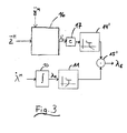
- a second embodiment of a method according to the invention is shown schematically.
- the time integration 10 of the motorcycle- fixed roll rate ⁇ M is the first calculation result (the first roll angle ⁇ 1 ), and here, for example, the first roll angle ⁇ 1 with a high-pass filter 11, for example, with a cutoff frequency f separation of 0.05 Hz, filtered.
- the second calculation result (the second roll angle variable ⁇ 2 ' ) is essentially determined from the motorcycle- fixed acceleration in the z-direction z M (block 16).
- the second roll angle size ⁇ 2 ' in block 17 can be multiplied by an empirical factor c.
- the second calculation result ⁇ 2 ' with a low-pass filter 14' for example, with the same corner frequency f separation as that of the high-pass filter 11, for example, 0.05 Hz, filtered.
- the filters 11, 14 'used are usually PT 1 components of the first order.
- the separation frequency f separation is, for example, in the range of about 0.01 Hz to about 0.10 Hz.
- ⁇ th arccos G z ⁇ M ⁇ - 1 ⁇ sign y ⁇ M
- sign (X) is the sign function, which has the value “1” if X is greater than zero, which is “0” if X equals zero, and which is "-1" if X is less than zero ,
- the total roll angle ⁇ ges can be approximated by the physically active roll angle ⁇ th : ⁇ ges ⁇ ⁇ th
- the second roll angle quantity ⁇ 2 ' is determined according to equation (9) (block 16).
- a third embodiment of a method according to the invention is shown schematically.
- the time integration 10 of the motorcycle- fixed roll rate ⁇ M is the first calculation result (the first roll angle ⁇ 1 ), and here, for example, the first roll angle ⁇ 1 with a high-pass filter 11, for example, with a cutoff frequency f separation of 0.05 Hz, filtered.
- the first roll angle ⁇ 1 with a high-pass filter 11, for example, with a cutoff frequency f separation of 0.05 Hz, filtered.
- the second calculation result (the second roll angle variable ⁇ 2 " ) is determined from two motorcycle- fixed accelerations, in particular a motorcycle- fixed acceleration in the z-direction z M and a motor-wheel-fixed acceleration in the y-direction ⁇ M (block 20) ).
- the second calculation result ⁇ 2 " is filtered with a low-pass filter 14", for example with the same corner frequency f separation as that of the high-pass filter 11, for example 0.05 Hz.
- the filters 11, 14 "used are usually PT 1 components of the first order
- the separation frequency f separation is, for example, in the range from about 0.01 Hz to about 0.10 Hz.
- the calculation of the second roll angle ⁇ 2 " from a motorcycle- fixed acceleration in the z-direction z ⁇ M and a motorcycle- fixed acceleration in the y-direction ⁇ M applies only to stationary cornering .
- the calculation includes the tire geometry and the dynamic tire behavior of the motorcycle.
- the factor k depends on the tire geometry and the dynamic tire behavior of the motorcycle.
- An advantage of the method according to the invention is that the roll angle ⁇ E of the motorcycle without delay, apart from time delays caused by the sensors, is present. Both in stationary and transient driving conditions, the roll angle ⁇ E can be determined. In addition, the accuracy of the roll angle determined by combining two calculation methods is greater than is possible with a single measurement method.
- a further advantage is that the production costs of a device for implementing the method according to the invention are significantly lower in comparison with high-precision inertial sensors with the same accuracy.
- a sensor cluster which For example, from the use in electronic stability programs (ESP) in passenger cars already known.
- ESP electronic stability programs
- Such a sensor cluster usually provides a rotation rate signal and one or two acceleration signals.
- Such a sensor cluster can optionally be installed rotated by 90 degrees.
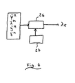
- the invention also relates to a method for determining the roll angle of a motorcycle while driving from the product of motorcycle-fixed yaw rate and driving speed of the motorcycle.
- a corresponding embodiment is shown schematically. From a motorcycle- fixed yaw rate ⁇ M and the vehicle speed v of the motorcycle, the product is formed (block 23). From the product is determined by means of a functional relationship, which is for example given in the form of a characteristic, a roll angle size (block 24). After filtering the calculation result with low-pass filter 25 results in the roll angle ⁇ E of the motorcycle.
- Filter 25 is usually a first order PT 1 member.
- the corner frequency is for example in the range of about 1 Hz.
- a combination of multiple filters is used to lower the signal peaks in fast slalom driving: a low-pass filter (corner frequency about 0.05 Hz), a high-pass filter (corner frequency about 0.05 Hz, gain 0.5), addition of both signals and possibly further filtering with a low-pass filter (corner frequency about 1 Hz) for signal smoothing.
- the roll angle ⁇ is a function f of the product ⁇ M ⁇ v of motorcycle- fixed yaw rate ⁇ M and vehicle speed v of the motorcycle (see equation (7)).
- a numerically determined characteristic curve is used (block 24) in order to determine the roll angle ⁇ from the product (block 23) of motorcycle- fixed yaw rate ⁇ M and vehicle speed v.
- the manufacturing cost of the device for implementing the method (determination of the roll angle of the product of motorized yaw rate and driving speed) are significantly lower with the same accuracy compared with high-precision inertial sensors.
- the position of the sensors on the motorcycle is not relevant, since the rotation rate is the same on the entire vehicle.
- the invention also relates to a method for checking the plausibility of a roll angle determination algorithm.
- the roll angle for the stationary driving state ie, the second roll angle size
- the roll angle for the stationary driving state can be determined in a redundant manner using different methods.
- a roll angle variable ⁇ 2 or ⁇ 2 " can be determined from the motorcycle- fixed yaw rate ⁇ M and the vehicle speed v as well as from the motorcycle- fixed lateral acceleration ⁇ M and the motorcycle- fixed lateral acceleration ⁇ M. Any choice of two or more roll angle determination methods is conceivable.
- an estimation of the trustworthiness of the roll angle ⁇ E determined by means of the roll angle size (n) is possible.
- the plausibility check / comparison may detect a sensor error. If there is a significant difference between the rolling angle variables ⁇ 2 , ⁇ 2 ' , ⁇ 2 " determined in a plurality of ways, it is possible to conclude that one of the acceleration sensors or yaw rate sensors malfunctions.
- the rolling rate ⁇ M must be zero during this period. Thus, an offset of the roll rate sensor can be determined and compensated.
- the integral of the roll rate ⁇ M is zero degrees.
- the linearity error of the roll rate sensor can be determined.
- a moving motorcycle must always be in an equilibrium position. This is necessary for both straight and cornering.
- the current driving situation is estimated in block 27 using one or more of the following variables: engine speed, engine torque, steering angle, vehicle speed v, vehicle acceleration, wheel speeds ⁇ i , road condition, wheel slip, vehicle load, road inclination.
- This assessment then flows into the calculation 26 of the roll angle ⁇ E.
- Fig. 7 an exemplary method for the adaptive calculation of a roll angle ⁇ E is shown schematically. To ensure a high accuracy, a combination of different methods for calculating the roll angle ⁇ E is used. At the same time, measurements of the roll rate ⁇ M , the yaw rate ⁇ M and the accelerations in the z and y directions z ⁇ M , ⁇ M are carried out, eg with a sensor cluster. The integral 30 of the roll rate ⁇ M is formed and the result ⁇ 1 is filtered with a high-pass filter 31.
- Properties of the system eg filter characteristics
Landscapes
- Engineering & Computer Science (AREA)
- Mechanical Engineering (AREA)
- Transportation (AREA)
- Physics & Mathematics (AREA)
- Automation & Control Theory (AREA)
- Mathematical Physics (AREA)
- Control Of Driving Devices And Active Controlling Of Vehicle (AREA)
- Regulating Braking Force (AREA)
Description
Die Erfindung betrifft ein Verfahren zur Bestimmung des Rollwinkels eines Kraftrades gemäß Oberbegriff von Anspruch 1 sowie eine Vorrichtung zur Bestimmung des Rollwinkels eines Kraftrades gemäß Oberbegriff von Anspruch 15.The invention relates to a method for determining the roll angle of a motorcycle according to the preamble of claim 1 and to a device for determining the roll angle of a motorcycle according to the preamble of
Moderne Motorrad-Antiblockiersysteme (ABS) und Integralbremssysteme sind bei Geradeausbremsungen und Bremsungen bei mittleren Schräglagen sehr weit entwickelt und damit relativ sicher. Bei größeren Schräglagen müssen die Parameter des Bremssystems (z.B. Bremskraftverteilung, Bremsdruckgradient und Regelstrategie) an die Kurvenfahrt angepasst werden, um auch hier ein sicheres Bremsen zu gewährleisten. Die Kenntnis des Schräglagenwinkels (Rollwinkels) ist dazu essentiell. Aber auch Kurvenlichtsysteme, Fahrwerksysteme und zukünftige Fahrdynamikregelsysteme erfordern den Rollwinkel als eine Eingangsgröße. Bekannte Systeme zur Messung des Rollwinkels während der Fahrt sind entweder zu ungenau oder zu teuer für Serienanwendungen. Die zugrunde liegenden Messprinzipien zur Bestimmung des Rollwinkels sind entweder nur für stationäre oder nur für instationäre Fahrsituationen geeignet.Modern motorcycle anti-lock braking systems (ABS) and integral braking systems are very well developed for straight braking and braking at medium inclinations and thus relatively safe. For larger inclinations, the parameters of the brake system (eg brake force distribution, brake pressure gradient and control strategy) must be adapted to cornering in order to ensure safe braking. The knowledge of the angle of inclination (roll angle) is essential. But also bend lighting systems, suspension systems and future vehicle dynamics control systems require the roll angle as an input variable. Known systems for measuring roll angle while driving are either too inaccurate or too expensive for mass production applications. The underlying measuring principles for determining the roll angle are either only suitable for stationary or only transient driving situations.
Aus der Schrift
In der Schrift
Ein Verfahren zur Bestimmung des Rollwinkels und des Nickwinkels eines zweirädrigen Fahrzeuges mit Hilfe eines adaptiven Filters wird in der
In der
Der Erfindung liegt die Aufgabe zugrunde, ein alternatives Verfahren und eine alternative Vorrichtung zur Bestimmung des Rollwinkels eines Kraftrades bereitzustellen, welches/welche eine zuverlässige Bestimmung des Rollwinkels bei gleichzeitig hoher Genauigkeit ermöglicht. Dabei sollen die Kosten zur Umsetzung des Verfahrens bzw. zur Herstellung der Vorrichtung gering sein.The invention has for its object to provide an alternative method and an alternative device for determining the roll angle of a motorcycle, which / which allows a reliable determination of the roll angle with high accuracy. The costs for implementing the method or for the production of the device should be low.
Diese Aufgabe wird erfindungsgemäß durch das Verfahren gemäß Anspruch 1 sowie die Vorrichtung gemäß Anspruch 14 gelöst.This object is achieved by the method according to claim 1 and the device according to
Dem erfindungsgemäßen Verfahren liegt der Gedanke zugrunde, die Ergebnisse bzw. Informationen aus zwei oder mehr unterschiedlichen Methoden zur Bestimmung eines Rollwinkels miteinander zu kombinieren, um so in allen Fahrsituationen (stationär oder instationär) unter Verwendung von kostengünstigen Sensoren einen hinreichend genauen Rollwinkel zu erhalten. Dazu wird anhand einer ersten Methode aus einer ermittelten Rollrate des Fahrzeugs eine erste Rollwinkelgröße bestimmt. Aus dem Produkt einer Gierrate und einer Fahrzeuggeschwindigkeit wird zumindest eine zweite Rollwinkelgröße bestimmt. Der Rollwinkel wird dann aus den mindestens zwei bestimmten Rollwinkelgrößen berechnet.The inventive method is based on the idea to combine the results or information from two or more different methods for determining a roll angle with each other, so as to obtain a sufficiently accurate roll angle in all driving situations (stationary or transient) using cost-effective sensors. For this purpose, a first roll angle variable is determined based on a first method from a determined roll rate of the vehicle. From the product of a yaw rate and a vehicle speed at least a second roll angle size is determined. The roll angle is then calculated from the at least two determined roll angle sizes.
Gemäß einer bevorzugten Ausführungsform des erfindungsgemäßen Verfahrens wird der Rollwinkel durch Addition aus den Rollwinkelgrößen berechnet.According to a preferred embodiment of the method according to the invention, the roll angle is calculated by addition from the roll angle sizes.
Außerdem ist es bevorzugt, dass die Rollwinkelgrößen gefiltert werden, bevor aus ihnen der Rollwinkel berechnet wird. Erfindungsgemäß wird die Rollrate mit einem Hochpassfilter gefiltert, bevor sie zur Berechnung der ersten Rollwinkelgröße herangezogen wird. So wird die Fehlertoleranz des erfindungsgemäßen Verfahrens erhöht. Es hat sich als besonders vorteilhaft herausgestellt, für die Filterung einen Hochpassfilter mit einer Eckfrequenz von etwa 0,01 Hz zu verwenden.In addition, it is preferable that the roll angle quantities are filtered before calculating the roll angle from them. According to the invention, the roll rate is filtered with a high-pass filter before it is used to calculate the first roll angle size. Thus, the fault tolerance of the method according to the invention is increased. It has proven to be particularly advantageous to use a high-pass filter with a corner frequency of about 0.01 Hz for the filtering.
Die Rollrate wird bevorzugt mittels eines Drehratensensors, welcher am Fahrzeug angebracht ist, ermittelt. Die Position des Drehratensensors am Motorrad ist nicht relevant, da die Drehraten am gesamten Fahrzeug gleich sind.The roll rate is preferably determined by means of a rotation rate sensor, which is mounted on the vehicle. The position the rate of rotation sensor on the motorcycle is not relevant, since the rotation rates are the same on the entire vehicle.
Bevorzugt wird aus der Rollrate durch zeitliche Integration eine erste Rollwinkelgröße berechnet. Für kleine Nickwinkel gleichen sich motorradfeste Rollrate und fahrbahnfeste Rollrate und eine Integration der motorradfesten Rollrate ergibt kurzzeitig eine den Rollwinkel repräsentierende Rollwinkelgröße.Preferably, a first roll angle size is calculated from the roll rate by temporal integration. For small pitch angles equal motorcycle-resistant roll rate and roadway Roll rate and an integration of the motorcycle-fixed roll rate results in a short time a roll angle representing the roll angle.
Gemäß einer bevorzugten Ausführungsform des erfindungsgemäßen Verfahrens wird die erste Rollwinkelgröße mit einem Hochpassfilter gefiltert, bevor sie zur Berechnung eines Rollwinkels herangezogen wird. Hierdurch werden Verfälschungen des Rollwinkels durch Messfehler des Drehratensensors verringert. Besonders bevorzugt wird ein Hochpassfilter mit einer Eckfrequenz von etwa 0,05 Hz verwendet.According to a preferred embodiment of the method according to the invention, the first roll angle variable is filtered with a high-pass filter before it is used to calculate a roll angle. As a result, distortions of the roll angle are reduced by measuring errors of the rotation rate sensor. More preferably, a high pass filter with a cutoff frequency of about 0.05 Hz is used.
Außerdem ist es vorteilhaft, die zweite Rollwinkelgröße mit einem Tiefpassfilter zu filtern, bevor sie zur Berechnung des Rollwinkels herangezogen wird, da die Zusammenhänge zwischen den fahrdynamischen Kenngrößen, welche der Bestimmung der zweiten Rollwinkelgröße zugrunde liegen, nur bei stationärer Kurvenfahrt gelten. Besonders bevorzugt wird ein Hochpassfilter mit einer Eckfrequenz von etwa 0,05 Hz verwendet.In addition, it is advantageous to filter the second roll angle variable with a low-pass filter before it is used to calculate the roll angle, since the relationships between the dynamic driving characteristics, which underlie the determination of the second roll angle, apply only to steady cornering. More preferably, a high pass filter with a cutoff frequency of about 0.05 Hz is used.
Bevorzugt beträgt die Eckfrequenz des Tiefpassfilters, welcher zur Filterung der zweiten Rollwinkelgröße verwendet wird, den gleichen oder etwa den gleichen Wert wie die Eckfrequenz des Hochpassfilters, welcher zur Filterung der ersten Rollwinkelgröße verwendet wird. Hierdurch wird eine lückenlose Bestimmung des Rollwinkels über den gesamten Frequenzbereich sichergestellt. Besonders bevorzugt liegt die Trennfrequenz im Bereich von etwa 0,01 Hz bis etwa 0,10 Hz. Ganz besonders bevorzugt beträgt die verwendete Trennfrequenz des Hochpass- und des Tiefpassfilters 0,05 Hz. Die Trennfrequenz wird vorteilhafterweise so gering wie möglich gewählt.Preferably, the cutoff frequency of the low pass filter used to filter the second roll angle quantity is the same or about the same as the cutoff frequency of the high pass filter used to filter the first roll angle size. This ensures a complete determination of the roll angle over the entire frequency range. The separation frequency is particularly preferably in the range from about 0.01 Hz to about 0.10 Hz. Most preferably, the separation frequency of the high-pass filter and the low-pass filter used is 0.05 Hz. The separation frequency is advantageously chosen as small as possible.
Bei einer Addition von mehr als zwei Rollwinkelgrößen werden die Eckfrequenzen der verwendeten Hochpass-, Bandpass und Tiefpassfilter derart gewählt, dass eine Bestimmung des Rollwinkels über den gesamten Frequenzbereich gegeben ist.With an addition of more than two roll angle sizes, the cutoff frequencies of the high-pass, bandpass and low-pass filters used are selected such that a determination of the roll angle over the entire frequency range is given.
Gemäß einer bevorzugten Ausführungsform des erfindungsgemäßen Verfahrens wird die zweite Rollwinkelgröße entweder aus dem Produkt einer Gierrate und einer Fahrzeuggeschwindigkeit oder aus einer Gierrate, einer Fahrzeuggeschwindigkeit und einer Vertikalbeschleunigung des Fahrzeugs oder aus einer Vertikalbeschleunigung des Fahrzeugs oder aus einer Vertikal- und einer Querbeschleunigung des Fahrzeugs ermittelt. Besonders bevorzugt wird die Gierrate durch einen Drehratensensor bestimmt. Die Fahrzeuggeschwindigkeit wird besonders bevorzugt aus den Messgrößen mindestens eines Raddrehzahlsensors bestimmt.According to a preferred embodiment of the method according to the invention, the second roll angle variable is determined either from the product of a yaw rate and a vehicle speed or from a yaw rate, a vehicle speed and a vertical acceleration of the vehicle or from a vertical acceleration of the vehicle or from a vertical and a lateral acceleration of the vehicle. Particularly preferably, the yaw rate is determined by a rotation rate sensor. The vehicle speed is particularly preferably determined from the measured variables of at least one wheel speed sensor.
Die Rollwinkelgröße(n) wird/werden bevorzugt anhand einer oder mehrerer in einem Steuergerät abgelegten Kennlinien oder mindestens eines in einem Steuergerät abgelegten Kennfeldes aus der/den jeweiligen fahrdynamischen Kenngröße(n) bestimmt. Besonders bevorzugt wird die Bestimmung über ein Kennfeld oder eine Kennlinie im Falle einer Ermittlung der zweiten Rollwinkelgröße aus Gierrate und Fahrzeuggeschwindigkeit vorgenommen.The roll angle variable (s) is / are preferably determined from one or more characteristic curves stored in a control unit or at least one characteristic map stored in a control unit from the respective driving dynamic parameter (s). Particularly preferably, the determination is made via a characteristic map or a characteristic curve in the case of a determination of the second roll angle variable of yaw rate and vehicle speed.
Alternativ wird/werden die zweite(n) Rollwinkelgröße(n) bevorzugt anhand eines Berechnungsalgorithmus aus der/den jeweiligen fahrdynamischen Kenngröße(n) berechnet.Alternatively, the second (n) roll angle variable (s) is / are preferably calculated on the basis of a calculation algorithm from the respective driving dynamic parameter (s).
Gemäß einer Weiterbildung des erfindungsgemäßen Verfahrens werden aus fahrdynamischen Kenngrößen zwei oder mehr zweite Rollwinkelgrößen auf unterschiedliche Art bestimmt. Diese auf verschiedene Weisen bestimmten zweiten Rollwinkelgrößen werden dann für eine Plausibilitätsprüfung des Rollwinkels verwendet. Besonders bevorzugt werden zur Plausibilitätsprüfung die auf unterschiedliche Arten und/oder aus verschiedenen fahrdynamischen Kenngrößen bestimmten zweiten Rollwinkelgrößen untereinander verglichen. Alternativ wird jeweils aus der ersten Rollwinkelgröße und einer der zweiten Rollwinkelgrößen ein Rollwinkel berechnet, und diese Rollwinkel untereinander verglichen. Ganz besonders bevorzugt wird mindestens eine der zweiten Rollwinkelgrößen aus mindestens einer Beschleunigung des Fahrzeugs bestimmt.According to a development of the method according to the invention, two or more second vehicle dynamics characteristic variables are obtained Rolling angle sizes determined in different ways. These second roll angle sizes determined in various ways are then used for a plausibility check of the roll angle. For a plausibility check, the second roll angle values determined in different ways and / or from different driving dynamics parameters are particularly preferably compared with one another. Alternatively, a roll angle is calculated in each case from the first roll angle size and one of the second roll angle sizes, and these roll angles are compared with one another. Most preferably, at least one of the second roll angle values is determined from at least one acceleration of the vehicle.
Bevorzugt wird anhand des Vergleichs der auf unterschiedliche Arten bestimmten zweiten Rollwinkelgrößen oder Rollwinkel eine Fehlfunktion eines verwendeten Sensors erkannt. Weicht die aus den Werten eines Sensors berechnete zweite Rollwinkelgröße von den anderen Rollwinkelgrößen ab, so liegt möglicherweise eine Fehlfunktion des Sensors vor. So ist eine schnelle und einfache Erkennung eines fehlerhaften Sensors möglich. Besonders bevorzugt wird so ein Fehler eines Beschleunigungssensors erkannt.A malfunction of a sensor used is preferably detected on the basis of the comparison of the second roll angle variables or roll angles determined in different ways. If the second roll angle quantity calculated from the values of a sensor deviates from the other roll angle sizes, the sensor may possibly malfunction. Thus, a quick and easy detection of a faulty sensor is possible. Particularly preferably, such an error of an acceleration sensor is detected.
Ebenso ist es bevorzugt, die ermittelten Beschleunigungswerte zur Bestimmung eines Offsets des Drehratensensors zur Bestimmung der Rollrate zu verwenden.It is likewise preferred to use the ascertained acceleration values for determining an offset of the rotation rate sensor for determining the roll rate.
Vorteilhafterweise wird mit Hilfe des so bestimmten Offsets ein Linearitätsfehler der Rollrate bestimmt. Dieser kann dann zur Korrektur der Rollrate verwendet werden, und so wird die Genauigkeit des erfindungsgemäßen Verfahrens weiter verbessert.Advantageously, a linearity error of the roll rate is determined with the aid of the offset thus determined. This can then be used to correct the roll rate, and so the accuracy of the method according to the invention is further improved.
Bevorzugt werden die Beschleunigungssensoren auch für die Berechnung des Rollwinkels bei Stillstand des Fahrzeuges verwendet.Preferably, the acceleration sensors are also used for the calculation of the roll angle at standstill of the vehicle.
Gemäß einer weiteren bevorzugten Ausführungsform des erfindungsgemäßen Verfahrens wird der Rollwinkel durch gewichtete Summation aus den mindestens zwei bestimmten Rollwinkelgrößen berechnet, wobei die entsprechenden Gewichtsparameter in Abhängigkeit von der aktuellen Fahrsituation angepasst werden. Die Fahrsituation wird dabei anhand von mindestens einer der folgenden Größen erkannt: Motordrehzahl, Motormoment, Lenkwinkel, Fahrzeuggeschwindigkeit, Fahrzeugbeschleunigung, Raddrehzahlen, Fahrbahnzustand, Rollrate, Gierrate, Rollwinkelbeschleunigung, Gierwinkelbeschleunigung, Rollwinkel, Radschlupf, Fahrzeugbeladung, Fahrbahnneigung. Der berechnete Rollwinkel wird besonders bevorzugt während der Optimierung der Gewichtsparameter als Eingangsgröße zur Beurteilung der Fahrsituation herangezogen (iterative Berechnung des Rollwinkels).According to a further preferred embodiment of the method according to the invention, the roll angle is calculated by weighted summation from the at least two determined roll angle values, wherein the corresponding weight parameters are adjusted as a function of the current driving situation. The driving situation is thereby recognized on the basis of at least one of the following variables: engine speed, engine torque, steering angle, vehicle speed, vehicle acceleration, wheel speeds, road condition, roll rate, yaw rate, roll angular acceleration, yaw angle acceleration, roll angle, wheel slip, vehicle load, road gradient. The calculated roll angle is particularly preferably used during the optimization of the weight parameters as an input variable for the assessment of the driving situation (iterative calculation of the roll angle).
Bevorzugt wird neben der ersten Rollwinkelgröße, welche aus der Rollrate bestimmt wird, eine zweite Rollwinkelgröße aus einer Vertikal- und einer Querbeschleunigung des Fahrzeugs bestimmt, sowie eine weitere zweite Rollwinkelgröße aus dem Produkt einer Gierrate und einer Fahrzeuggeschwindigkeit bestimmt, und aus den drei, insbesondere mit einem Hoch- oder Tiefpassfilter gefilterten, Rollwinkelgrößen durch gewichtete Summation mit Gewichtsparametern der Rollwinkel berechnet, wobei die Gewichtsparameter in Abhängigkeit von der aktuellen Fahrsituation angepasst werden, welche anhand mindestens einer der folgenden Größen erkannt wird: Motordrehzahl, Motormoment, Lenkwinkel, Fahrzeuggeschwindigkeit, Fahrzeugbeschleunigung, Raddrehzahlen, Fahrbahnzustand, Rollrate, Gierrate, Rollwinkelbeschleunigung, Gierwinkelbeschleunigung, Rollwinkel, Radschlupf, Fahrzeugbeladung und Fahrbahnneigung.In addition to the first roll angle variable, which is determined from the roll rate, a second roll angle variable is determined from a vertical and a lateral acceleration of the vehicle, and a further second roll angle variable is determined from the product of a yaw rate and a vehicle speed, and from the three, in particular with a weighted summation with weight parameters of the roll angle calculated, the weight parameters are adjusted depending on the current driving situation, which is recognized by at least one of the following variables: engine speed, engine torque, steering angle, vehicle speed, vehicle acceleration, wheel speeds , Road condition, Roll rate, yaw rate, roll angular acceleration, yaw angular acceleration, roll angle, wheel slip, vehicle load, and road grade.
Es ist ebenso bevorzugt, dass die Eigenschaften der zur Filterung der Rollwinkelgrößen verwendeten Filter in Abhängigkeit von der aktuellen Fahrsituation gewählt werden. Besonders bevorzugt werden die Trennfrequenzen der Filter in Abhängigkeit von der aktuellen Fahrsituation gewählt.It is also preferred that the properties of the filters used for filtering the roll angle quantities are selected as a function of the current driving situation. Particularly preferably, the cut-off frequencies of the filters are selected as a function of the current driving situation.
Der erfindungsgemäßen Vorrichtung liegt der Gedanke zugrunde, durch eine addierende Schaltung mindestens zwei Rollwinkelgrößen zu einem Rollwinkel aufzuaddieren, wobei eine erste Rollwinkelgröße aus einer Rollrate des Fahrzeugs bestimmt wird und eine zweite Rollwinkelgröße mit Hilfe mindestens einer fahrdynamischen Kenngröße bestimmt wird.The device according to the invention is based on the idea of adding at least two roll angle variables to a roll angle by means of an adding circuit, wherein a first roll angle variable is determined from a roll rate of the vehicle and a second roll angle variable is determined with the aid of at least one dynamic driving parameter.
Gemäß einer Weiterbildung der erfindungsgemäßen Vorrichtung umfasst diese mindestens eine Auswerteeinheit, in welcher eine integrierende Schaltung enthalten ist, mit welcher aus der Rollrate durch Integration die erste Rollwinkelgröße bestimmt wird. Dabei umfasst die Vorrichtung besonders bevorzugt einen Filter, mit welchem die Rollrate gefiltert wird, bevor sie aufintegriert wird.According to a development of the device according to the invention, this comprises at least one evaluation unit, in which an integrating circuit is contained, with which from the roll rate by integration, the first roll angle size is determined. In this case, the device particularly preferably comprises a filter with which the roll rate is filtered before it is integrated.
Die erfindungsgemäße Vorrichtung umfasst vorteilhafterweise mindestens eine Auswerteeinheit mit einem Hochpassfilter, mit welchem die erste Rollwinkelgröße gefiltert wird, bevor sie zur Berechnung des Rollwinkels verwendet wird.The device according to the invention advantageously comprises at least one evaluation unit with a high-pass filter, with which the first roll angle size is filtered before it is used to calculate the roll angle.
Des Weiteren umfasst die Vorrichtung in mindestens einer Auswerteeinheit bevorzugt einen Tiefpassfilter, mit welchem auch die zweite Rollwinkelgröße gefiltert wird, bevor sie zur Berechnung des Rollwinkels herangezogen wird.Furthermore, the device in at least one evaluation unit preferably comprises a low-pass filter, with which Also, the second roll angle size is filtered before it is used to calculate the roll angle.
Bevorzugt besitzt der Tiefpassfilter zur Filterung der zweiten Rollwinkelgröße die gleich oder etwa gleich Eckfrequenz wie der Hochpassfilter zur Filterung der ersten Rollwinkelgröße. Hierdurch wird bei der nachfolgenden Addition der Rollwinkelgrößen eine lückenlose Bestimmung des Rollwinkels über den gesamten Frequenzbereich sichergestellt.The low-pass filter for filtering the second roll angle variable preferably has the same or approximately the same corner frequency as the high-pass filter for filtering the first roll angle variable. As a result, a complete determination of the roll angle over the entire frequency range is ensured in the subsequent addition of the roll angle sizes.
Gemäß einer bevorzugten Ausführungsform der erfindungsgemäßen Vorrichtung umfasst mindestens eine Auswerteeinheit eine Schaltung, mit welcher aus einer Gierrate und einer Fahrzeuggeschwindigkeit, oder aus einer Gierrate, einer Fahrzeuggeschwindigkeit und einer Vertikalbeschleunigung des Fahrzeugs, oder aus einer Vertikalbeschleunigung des Fahrzeugs, oder aus einer Vertikal- und einer Querbeschleunigung des Fahrzeugs die zweite Rollwinkelgröße bestimmt wird.According to a preferred embodiment of the device according to the invention, at least one evaluation unit comprises a circuit with a yaw rate and a vehicle speed, or from a yaw rate, a vehicle speed and a vertical acceleration of the vehicle, or from a vertical acceleration of the vehicle, or from a vertical Transverse acceleration of the vehicle, the second roll angle size is determined.
Bevorzugt ist das Mittel zur Ermittlung der Rollrate und/oder das Mittel zur Ermittlung der Gierrate des Fahrzeugs ein oder mehrere Drehratensensoren. Besonders bevorzugt wird/werden ein/die Drehratensensor(en) verwendet, welcher bereits im Rahmen von Fahrdynamik-Regelsystemen in Kraftfahrzeugen bekannt ist/sind.The means for determining the roll rate and / or the means for determining the yaw rate of the vehicle are preferably one or more yaw rate sensors. Particularly preferred is / are the yaw rate sensor (s) used, which is already known in the context of vehicle dynamics control systems in motor vehicles / are.
Das Mittel zur Ermittlung der Geschwindigkeit des Fahrzeugs ist bevorzugt mindestens ein Raddrehzahlsensor. Ein solcher ist üblicherweise im Rahmen eines Antiblockiersystems bereits im Fahrzeug vorhanden.The means for determining the speed of the vehicle is preferably at least one wheel speed sensor. Such is usually already present in the vehicle as part of an antilock braking system.
Gemäß einer bevorzugten Ausführungsform der erfindungsgemäßen Vorrichtung ist das Mittel zur Ermittlung mindestens einer Beschleunigung ein Beschleunigungssensor oder eine Gruppe von Beschleunigungssensoren. Besonders bevorzugt handelt es sich dabei um einen Sensor eines fahrdynamischen Regelsystems, ganz besonders bevorzugt um einen Sensor eines elektronischen Stabilitätsprogramms (ESP). Solche Sensoren sind technisch ausgereift und damit ohne zusätzliche Entwicklungskosten einsetzbar.According to a preferred embodiment of the device according to the invention, the means for determining at least one acceleration is an acceleration sensor or a group of acceleration sensors. Particularly preferably, this is a sensor of a vehicle dynamics control system, very particularly preferably a sensor of an electronic stability program (ESP). Such sensors are technically mature and can therefore be used without additional development costs.
Ein Vorteil der Erfindung liegt darin, dass unter Verwendung von bereits im Stand der Technik bekannten Sensoren eine kostengünstige und dabei genaue Bestimmung des Rollwinkels des Fahrzeuges möglich ist.An advantage of the invention is that using sensors already known in the prior art, a cost-effective and accurate determination of the roll angle of the vehicle is possible.
Die Erfindung umfasst auch die Verwendung eines erfindungsgemäßen Verfahrens in mindestens einem der folgenden Systeme: elektronisch gesteuertes Bremssystem, Kurvenlichtsystem, Fahrwerksystem, elektrisches Lenksystem und Fahrdynamikregelsystem.The invention also includes the use of a method according to the invention in at least one of the following systems: electronically controlled braking system, cornering light system, suspension system, electric steering system and vehicle dynamics control system.
Weitere bevorzugte Ausführungsformen der Erfindung ergeben sich aus den Unteransprüchen und der nachfolgenden Beschreibung anhand von Figuren.Further preferred embodiments of the invention will become apparent from the subclaims and the following description with reference to figures.
Es zeigen
- Fig. 1
- eine schematische Darstellung eines Motorrades in Schräglage,
- Fig. 2
- eine schematische Darstellung eines ersten Ausführungsbeispieles eines erfindungsgemäßen Verfahrens,
- Fig. 3
- eine schematische Darstellung eines zweiten Ausführungsbeispieles eines erfindungsgemäßen Verfahrens,
- Fig. 4
- eine schematische Darstellung eines dritten Ausführungsbeispieles eines erfindungsgemäßen Verfahrens,
- Fig. 5
- eine schematische Darstellung eines Verfahrens zur Bestimmung eines Rollwinkels,
- Fig. 6
- eine schematische Darstellung eines vierten Ausführungsbeispieles eines erfindungsgemäßen Verfahrens, und
- Fig. 7
- in schematischer Darstellung ein beispielsgemäßes Verfahren zur adaptiven Berechnung eines Rollwinkels zur Verwendung in dem in
Fig. 7 dargestellten, vierten Ausführungsbeispiel.
- Fig. 1
- a schematic representation of a motorcycle in an inclined position,
- Fig. 2
- a schematic representation of a first embodiment of a method according to the invention,
- Fig. 3
- a schematic representation of a second embodiment of a method according to the invention,
- Fig. 4
- a schematic representation of a third embodiment of a method according to the invention,
- Fig. 5
- a schematic representation of a method for determining a roll angle,
- Fig. 6
- a schematic representation of a fourth embodiment of a method according to the invention, and
- Fig. 7
- a schematic representation of an exemplary method for adaptively calculating a roll angle for use in the in
Fig. 7 illustrated, fourth embodiment.
Kern der Vorrichtung bzw. des Verfahrens zur Bestimmung des Rollwinkels (Neigungswinkels) eines Fahrzeuges, insbesondere Motorrades, während der Fahrt ist die Kombination von mindestens zwei einzelnen Berechnungsergebnissen (für stationäre Fahrt und instationäre Fahrt), insbesondere mittels eines bestimmten Filters.Core of the device or the method for determining the roll angle (inclination angle) of a vehicle, in particular motorcycle, while driving is the combination of at least two individual calculation results (for stationary and unsteady ride), in particular by means of a specific filter.
In
Bei üblichen Reifen liegt der Gesamtrollwinkel λges ungefähr 10% bis 20% über dem physikalisch wirksamen Rollwinkel λth . Die Differenz zwischen Gesamtrollwinkel λges und physikalisch wirksamen Rollwinkel λth wird auch als Zusatzrollwinkel λZS bezeichnet. Es gilt also: ![]()
![]()
Bei üblichen Reifen liegt der reifenbreitenbedingte Zusatzrollwinkel λZS , wie oben bereits erwähnt, in der Größenordnung von ungefähr 10% bis 20% von dem physikalisch wirksamen Rollwinkel λth . Da λZS klein gegenüber λth ist, wird oftmals der Gesamtrollwinkel λges durch den physikalisch wirksamen Rollwinkel λth angenähert: 
Für kleine Nickwinkel gleichen sich motorradfeste Rollrate λ̇M und fahrbahnfeste Rollrate λ̇Fahrbahn . Eine Integration der Rollrate λ̇M führt zum (Gesamt) Rollwinkel λges (dies entspricht in den Ausführungsbeispielen der
In
Die Berechnung der ersten Rollwinkelgröße λ 1 durch Integration 10 der motorradfesten Rollrate λ̇M gilt sowohl für stationäre als auch für instationäre Fahrt. Jedoch ist die Berechnung durch die Integration 10 des Messfehlers der Rollrate λ̇M nicht langzeitstabil, d.h. das Ergebnis ist nur kurzzeitig gültig. Je nach Ausführung und Genauigkeit des verwendeten Rollratensensors beträgt die Steigerung des Messfehlers (so genannter "Drift") zwischen 1 Grad/Minute und 1 Grad/Sekunde.The calculation of the first roll angle λ 1 by
Zur Vermeidung von Überlauffehlern bei der Integration 10 können gemäß eines nicht dargestellten Ausführungsbeispiels die Funktionen Integration 10 und Hochpassfilter 11 in ein äquivalentes Tiefpassfilter mit zusätzlicher Verstärkung übergeführt werden.To avoid overflow errors in the
Die Berechnung der zweiten Rollwinkelgröße λ 2 aus motorradfester Gierrate ψ̇M und Fahrzeuggeschwindigkeit v gilt nur für stationäre Kurvenfahrt. Funktion 13 ist abhängig von der Reifengeometrie und dem dynamischen Reifenverhalten des Motorrades.The calculation of the second roll angle parameter λ 2 from the motorcycle- fixed yaw rate ψ̇ M and the vehicle speed v applies only to stationary cornering.
Die verwendeten Filter 11, 14 sind üblicherweise PT1-Glieder erster Ordnung. Die Trennfrequenz fTrenn liegt z.B. im Bereich von etwa 0,01 Hz bis etwa 0,10 Hz.The
Zur Begründung des Zusammenhanges von Gierrate ψ̇M , Fahrzeuggeschwindigkeit v und Rollwinkel λ wird folgendes erläutert:
- Für stationäre Kurvenfahrt gilt, dass die motorradfeste Gierrate ψ̇M durch die fahrbahnfeste Gierrate ψ̇Fahrbahn multipliziert mit dem Kosinus des Gesamtrollwinkels λges und die Nickwinkelgeschwindigkeit ν̇Fahrbahn gegeben ist, wobei allerdings die Nickwinkelgeschwindigkeit ν̇Fahrbahn bei stationärer Fahrt Null ist (ν̇Fahrbahn =0), so dass der zweite Term sinλges ·ν̇Fahrbahn in Gleichung (2) entfällt:

- Für stationäre Kurvenfahrt gelten weiterhin folgende Beziehungen zwischen der Querbeschleunigung ÿh im horizontierten Koordinatensystem (Koordinatensystem, welches bzgl. des motorradfesten Koordinatensystems um die x-Achse gedreht ist, so dass die horizontierte Querbeschleunigung ÿh parallel zur Fahrbahn verläuft), Fahrzeuggeschwindigkeit v, fahrbahnfester Gierrate ψ̇Fahrbahn , Tangens des wirksamen Rollwinkels λth und Erdbeschleunigung g:


- For stationary cornering applies that the motorcycle- fixed yaw rate ψ̇ M by the roadway yaw rate ψ̇ lane multiplied by the cosine of the total rolling angle λ ges and the pitch angle speed ν̇ lane is given, however, the pitch angle speed ν̇ lane at stationary ride is zero (ν̇ lane = 0) , so that the second term sin λ ges · ν̇ roadway in equation (2) is omitted:
- For stationary cornering, the following relationships between the lateral acceleration ÿ h in the horizontal coordinate system (coordinate system, which is rotated about the x-axis with respect to the motorcycle-fixed coordinate system, so that the horizontal lateral acceleration ÿ h runs parallel to the roadway), vehicle speed v, lane-yaw rate, continue to apply ψ̇ road , tangent of the effective roll angle λ th and gravitational acceleration g:
Einsetzen von (2) in (4) liefert: 
![]()
![]()
Unter der Annahme λges =λth kann dies auch vereinfacht werden zu: ![]()
![]()
Es gilt also, dass der Rollwinkel λth eine Funktion f des Produktes ψ̇M ·v von motorradfester Gierrate ψ̇M und Fahrgeschwindigkeit v des Motorrades ist: ![]()
![]()
Der funktionale Zusammenhang f(λth ) bzw. die obige Gleichung (7) ist nicht geschlossen lösbar. Daher wird eine numerisch ermittelte Kennlinie verwendet (Block 13), um aus dem Produkt (Block 12) von motorradfester Gierrate ψ̇M und Fahrgeschwindigkeit v den Rollwinkel λth (gemäß dem in
In
Die verwendeten Filter 11, 14' sind üblicherweise PT1-Glieder erster Ordnung. Die Trennfrequenz fTrenn liegt z.B. im Bereich von etwa 0,01 Hz bis etwa 0,10 Hz.The
Die Berechnung der zweiten Rollwinkelgröße λ 2 ' aus einer motorradfesten Beschleunigung in z-Richtung z̈M gilt nur für stationäre Kurvenfahrt. Außerdem basiert sie, wenn der Faktor c nicht berücksichtigt wird (c=1), auf der Annahme ideal schmaler Reifen. Allerdings ist die motorradfeste Beschleunigung in z-Richtung z̈M nicht Vorzeichen behaftet, so dass eine weitere Information, z.B. die motorradfeste Beschleunigung in y-Richtung ÿM , zur Festlegung des korrekten Vorzeichens des Rollwinkels λ herangezogen werden kann.The calculation of the second roll angle λ 2 ' from a motorcycle- fixed acceleration in the z direction z̈ M applies only to stationary cornering. Moreover, if factor c is not taken into account (c = 1), it is based on the assumption of ideal narrow tires. However, the motorcycle- fixed acceleration in z-direction z̈ M is not signed, so that further information, such as the motorcycle fixed acceleration in y-direction ÿ M , can be used to determine the correct sign of the roll angle λ .
Zur Begründung des Zusammenhanges von motorradfester Beschleunigung in z-Richtung z̈M und Rollwinkel λ wird folgendes erläutert:
- Für stationäre Kurvenfahrt gilt, dass der physikalisch wirksame Rollwinkel λth durch den Arcuskosinus des Quotienten von Erdbeschleunigung g zu motorradfester Vertikalbeschleunigung z̈M gegeben ist:

- For stationary cornering applies that the physically effective roll angle λ th is given by the arc cosine of the quotient of gravitational acceleration g to motorbike fixed vertical acceleration z̈ M :
Zur Festlegung des korrekten Vorzeichens kann die motorradfeste Querbeschleunigung ÿM herangezogen werden: ![]()
![]()
Dabei ist sign(X) die Vorzeichenfunktion, welche den Wert "1" besitzt, wenn X größer als Null ist, welche "0" ist, wenn X gleich Null ist, und welche "-1" ist, wenn X kleiner als Null ist.Where sign (X) is the sign function, which has the value "1" if X is greater than zero, which is "0" if X equals zero, and which is "-1" if X is less than zero ,
Wie oben bereits erwähnt, kann der Gesamtrollwinkel λges durch den physikalisch wirksamen Rollwinkel λth angenähert werden: 
Beispielsgemäß wird die zweite Rollwinkelgröße λ 2 ' gemäß Gleichung (9) bestimmt (Block 16).By way of example, the second roll angle quantity λ 2 'is determined according to equation (9) (block 16).
In
Die verwendeten Filter 11, 14" sind üblicherweise PT1-Glieder erster Ordnung. Die Trennfrequenz fTrenn liegt z.B. im Bereich von etwa 0,01 Hz bis etwa 0,10 Hz.The
Die Berechnung der zweiten Rollwinkelgröße λ 2 " aus einer motorradfesten Beschleunigung in z-Richtung z̈M und einer motorradfesten Beschleunigung in y-Richtung ÿM gilt nur für stationäre Kurvenfahrt. In die Berechnung gehen die Reifengeometrie und das dynamische Reifenverhalten des Motorrades ein.The calculation of the second roll angle λ 2 " from a motorcycle- fixed acceleration in the z-direction z̈ M and a motorcycle- fixed acceleration in the y-direction ÿ M applies only to stationary cornering .. The calculation includes the tire geometry and the dynamic tire behavior of the motorcycle.
Zur Begründung des Zusammenhanges von motorradfester Beschleunigung in z-Richtung z̈M , motorradfester Beschleunigung in y-Richtung ÿM und Rollwinkel λ wird folgendes erläutert:
- Wie oben bereits erwähnt, gilt folgender Zusammenhang:

- As already mentioned above, the following relationship applies:
Entsprechend Gleichung (8) gilt für stationäre Kurvenfahrt, dass der physikalisch wirksame Rollwinkel λth durch den Arcuskosinus des Quotienten von Erdbeschleunigung g zu motorradfester Vertikalbeschleunigung z̈M gegeben ist: ![]()
![]()
Außerdem gilt für stationäre Kurvenfahrt, dass der Zusatzrollwinkel λZS durch den Arcustangens des Quotienten von motorradfester Querbeschleunigung ÿM zu motorradfester Vertikalbeschleunigung z̈M gegeben ist: 
Einsetzen von Gleichungen (11) und (12) in (10) liefert: 
Beispielsgemäß wird der Gesamtrollwinkel λges als ein Vielfaches k des reifenbreitenbedingten Zusatzrollwinkels λZS angenähert. Er errechnet sich damit nach folgender Beziehung (Block 20): 
Dabei ist der Faktor k abhängig von der Reifengeometrie und dem dynamischen Reifenverhalten des Motorrades. Ein beispielsgemäßer Wert ist k=9,7.The factor k depends on the tire geometry and the dynamic tire behavior of the motorcycle. An example value is k = 9.7.
Ein Vorteil des erfindungsgemäßen Verfahrens liegt darin, dass der Rollwinkel λE des Motorrades ohne Zeitverzug, abgesehen von Zeitverzögerungen hervorgerufen durch die Sensoren, vorliegt. Sowohl bei stationären als auch bei instationären Fahrzuständen kann der Rollwinkel λE bestimmt werden. Außerdem ist die Genauigkeit des durch Kombination zweier Berechnungsmethoden bestimmten Rollwinkels größer, als dies mit einem einzelnen Messverfahren möglich ist.An advantage of the method according to the invention is that the roll angle λ E of the motorcycle without delay, apart from time delays caused by the sensors, is present. Both in stationary and transient driving conditions, the roll angle λ E can be determined. In addition, the accuracy of the roll angle determined by combining two calculation methods is greater than is possible with a single measurement method.
Die zeitliche Integration der Rollrate für sich alleine ist als Verfahren zur Ermittlung eines Rollwinkels nicht geeignet. Aufgrund des mit der Zeit ansteigenden Messfehlers kann dieses Verfahren mit Standard-Sensorik nicht direkt angewendet werden.The temporal integration of the roll rate alone is not suitable as a method for determining a roll angle. Due to the increasing measuring error over time, this method can not be used directly with standard sensors.
Ein weiterer Vorteil ist, dass die Herstellungskosten eines Gerätes zur Umsetzung des erfindungsgemäßen Verfahrens im Vergleich mit hochgenauer Inertialsensorik bei gleicher Genauigkeit deutlich geringer sind.A further advantage is that the production costs of a device for implementing the method according to the invention are significantly lower in comparison with high-precision inertial sensors with the same accuracy.
Im Vergleich zum ersten Ausführungsbeispiel (
Bei Kombination der Ergebnisse von zeitlicher Integration 10 der motorradfesten Rollrate λ̇M und der Funktion 13 des Produktes 12 von motorradfester Gierrate ψ̇M und Fahrgeschwindigkeit v des Motorrades (erstes Ausführungsbeispiel) ist es von Vorteil, dass die Position der Sensorik am Motorrad nicht relevant ist, da die Drehraten am gesamten Fahrzeug gleich sind.Combining the results of
Die Erfindung betrifft außerdem ein Verfahren zur Bestimmung des Rollwinkels eines Motorrades während der Fahrt aus dem Produkt von motorradfester Gierrate und Fahrgeschwindigkeit des Motorrades. In
Filter 25 ist üblicherweise ein PT1-Glied erster Ordnung. Die Eckfrequenz liegt z.B. im Bereich von etwa 1 Hz.
Gemäß eines nicht dargestellten Ausführungsbeispiels wird zur Absenkung der Signalspitzen bei schneller Slalomfahrt eine Kombination mehrerer Filter verwendet: ein Tiefpassfilter (Eckfrequenz etwa 0,05 Hz), ein Hochpassfilter (Eckfrequenz etwa 0,05 Hz, Verstärkungsfaktor 0,5), Addition beider Signale und eventuell weitere Filterung mit einem Tiefpassfilter (Eckfrequenz etwa 1 Hz) zur Signalglättung.According to an embodiment, not shown, a combination of multiple filters is used to lower the signal peaks in fast slalom driving: a low-pass filter (corner frequency about 0.05 Hz), a high-pass filter (corner frequency about 0.05 Hz, gain 0.5), addition of both signals and possibly further filtering with a low-pass filter (corner frequency about 1 Hz) for signal smoothing.
Gemäß der obigen Erläuterungen (Gleichungen (2) bis (7)) ist der Rollwinkel λ eine Funktion f des Produktes ψ̇M ·v von motorradfester Gierrate ψ̇M und Fahrgeschwindigkeit v des Motorrades (siehe Gleichung (7)). Es wird eine numerisch ermittelte Kennlinie verwendet (Block 24), um aus dem Produkt (Block 23) von motorradfester Gierrate ψ̇M und Fahrgeschwindigkeit v den Rollwinkel λ zu bestimmen.According to the above explanation (equations (2) to (7)), the roll angle λ is a function f of the product ψ̇ M · v of motorcycle- fixed yaw rate ψ̇ M and vehicle speed v of the motorcycle (see equation (7)). A numerically determined characteristic curve is used (block 24) in order to determine the roll angle λ from the product (block 23) of motorcycle- fixed yaw rate ψ̇ M and vehicle speed v.
Die Herstellungskosten des Gerätes zur Umsetzung des Verfahrens (Bestimmung des Rollwinkels aus dem Produkt von motorradfester Gierrate und Fahrgeschwindigkeit) sind bei gleicher Genauigkeit im Vergleich mit hochgenauer Inertialsensorik deutlich geringer. Die Position der Sensorik am Motorrad ist nicht relevant, da die Drehrate am gesamten Fahrzeug gleich ist.The manufacturing cost of the device for implementing the method (determination of the roll angle of the product of motorized yaw rate and driving speed) are significantly lower with the same accuracy compared with high-precision inertial sensors. The position of the sensors on the motorcycle is not relevant, since the rotation rate is the same on the entire vehicle.
Weiter oben werden Verfahren zur Bestimmung eines Rollwinkels basierend auf Beschleunigungsmessung (z̈M oder z̈M , ÿM ) und Messung der Rollrate λ̇M beschrieben. Die Fehlertoleranz dieser Verfahren kann durch Filterung der Rollrate λ̇M mit einem Hochpassfilter erster Ordnung, z.B. mit einer Eckfrequenz von etwa 0,01 Hz, erhöht werden.Further above, methods for determining a roll angle based on acceleration measurement ( z̈ M or z̈ M , ÿ M ) and measuring the roll rate λ̇ M are described. The error tolerance of these methods can be increased by filtering the roll rate λ̇ M with a first-order high-pass filter, for example with a corner frequency of approximately 0.01 Hz.
Die Erfindung betrifft außerdem ein Verfahren zur Plausibilisierung des Messwertes eines Rollwinkel-Bestimmungs-Algorithmus. Zur Plausibilisierung des Verfahrens kann der Rollwinkel für den stationären Fahrzustand, d.h. die zweite Rollwinkelgröße, auf redundante Weise mit unterschiedlichen Methoden bestimmt werden. Beispielsweise kann aus der motorradfesten Gierrate ψ̇M und der Fahrgeschwindigkeit v sowie aus der motorradfesten Vertikalbeschleunigung z̈M und der motorradfesten Querbeschleunigung ÿM je eine Rollwinkelgröße λ 2 bzw. λ 2 " bestimmt werden. Jede Wahl von zwei oder mehr Rollwinkel-Bestimmungsmethoden ist denkbar. Durch Vergleich der Ergebnisse ist eine Einschätzung der Vertrauenswürdigkeit des mittels der Rollwinkelgröße(n) bestimmten Rollwinkels λE möglich.The invention also relates to a method for checking the plausibility of a roll angle determination algorithm. To check the plausibility of the method, the roll angle for the stationary driving state, ie, the second roll angle size, can be determined in a redundant manner using different methods. For example, a roll angle variable λ 2 or λ 2 " can be determined from the motorcycle- fixed yaw rate ψ̇ M and the vehicle speed v as well as from the motorcycle- fixed lateral acceleration ̈ M and the motorcycle- fixed lateral acceleration ÿ M. Any choice of two or more roll angle determination methods is conceivable. By comparing the results, an estimation of the trustworthiness of the roll angle λ E determined by means of the roll angle size (n) is possible.
Außerdem kann durch die Plausibilisierung / den Vergleich unter Umständen ein Sensorfehler erkannt werden. Besteht eine erhebliche Differenz zwischen den auf mehrfache Art bestimmten Rollwinkelgrößen λ 2, λ 2 ' , λ 2 " , so kann auf eine Fehlfunktion eines der Beschleunigungssensoren oder Drehratensensoren geschlossen werden.In addition, the plausibility check / comparison may detect a sensor error. If there is a significant difference between the rolling angle variables λ 2 , λ 2 ' , λ 2 " determined in a plurality of ways, it is possible to conclude that one of the acceleration sensors or yaw rate sensors malfunctions.
Messen die vorhandenen Beschleunigungssensoren konstante Werte über einen bestimmten Zeitraum, so muss die Rollrate λ̇M in diesem Zeitraum Null sein. Damit kann ein Offset des Rollratensensors bestimmt und ausgeglichen werden.If the existing acceleration sensors measure constant values over a certain period of time, the rolling rate λ̇ M must be zero during this period. Thus, an offset of the roll rate sensor can be determined and compensated.
Zwischen zwei beliebigen Fahrzuständen mit einem Rollwinkel von Null Grad beträgt das Integral der Rollrate λ̇M Null Grad. Bei bekanntem Offset des Rollratensensors kann mit dieser Bedingung der Linearitätsfehler des Rollratensensors bestimmt werden.Between two arbitrary driving conditions with a roll angle of zero degrees, the integral of the roll rate λ̇ M is zero degrees. With known offset of the roll rate sensor can with this condition the linearity error of the roll rate sensor can be determined.
Sicherheitskritische Systeme benötigen eine Information über die Verlässlichkeit des Rollwinkelsignals. Diese Verlässlichkeit kann anhand des beschriebenen Verfahrens zur Plausibilisierung bestimmt werden.Safety-critical systems require information about the reliability of the roll angle signal. This reliability can be determined by the method described for plausibility.
Ein fahrendes Motorrad muss sich immer in einer Gleichgewichtsposition befinden. Dies ist sowohl für die Geradeausals auch für die Kurvenfahrt notwendig. Die Gleichgewichtsposition des Motorrades ist von vielen verschiedenen Faktoren abhängig, z.B. der Fahrzeuggeschwindigkeit v, dem Reibwert zwischen Reifen und Fahrbahn, den Raddrehzahlen ωi (i = 1 oder 2 für Vorderrad oder Hinterrad), der Motordrehzahl, dem Lenkwinkel, der Fahrzeugsbeladung, der Fahrbahnneigung etc. Diese Faktoren beeinflussen die Gleichgewichtswerte für die Rollrate λ̇M , die Gierrate ψ̇M und die drei Komponenten der Fahrzeugbeschleunigung ẍM , ÿM und z̈M. A moving motorcycle must always be in an equilibrium position. This is necessary for both straight and cornering. The equilibrium position of the motorcycle depends on many different factors, eg the vehicle speed v, the friction between the tire and the road, the wheel speeds ω i (i = 1 or 2 for the front or rear wheel), the engine speed, the steering angle, the vehicle load, the road inclination etc. These factors influence the equilibrium values for the roll rate λ̇ M , the yaw rate ψ̇ M and the three components of the vehicle acceleration ẍ M , ÿ M and z̈ M.
In
Es muss auch berücksichtigt werden, dass sich der theoretische Rollwinkel λth und der Gesamtrollwinkel λges unterscheiden, da die Reifenbreite ungleich Null ist.It must also be considered that the theoretical roll angle λ th and the total roll angle λ ges differ, since the tire width is not equal to zero.
In
Eigenschaften des Systems (z.B. Filtereigenschaften), wie z.B. die Trennfrequenzen der einzelnen Filter 31, 33, 35 und/oder die Gewichtungsparameter P1, P2, P3 werden in Abhängigkeit von der aktuellen Fahrsituation 27 geändert, welche durch mindestens eine der oben genannten Größen erkannt wird, z.B. Fahrzeuggeschwindigkeit v, Radschlupf, Raddrehzahlen ωi, Motordrehzahlen, Lenkwinkel, Fahrzeugbeladung, Fahrbahnneigung, Rollrate λ̇M , Gierrate ψ̇M , Rollwinkelbeschleunigung, Gierwinkelbeschleunigung, Rollwinkel λE (z.B. zuvor berechnet). Die Abhängigkeiten der Systemeigenschaften, z.B. der Trennfrequenzen der Filter und der Gewichtsparameter P1, P2, P3, von diesen Größen werden empirisch oder theoretisch ermittelt, in einem Steuergerät in Form von Kennlinien oder -feldern oder Berechnungsvorschriften abgelegt und bei der Berechnung des Rollwinkels berücksichtigt. Durch eine automatische (anhand der abgelegten Kennlinien, -felder oder Berechnungsalgorithmen) Änderung der Parameter lässt sich das System für jede Fahrsituation adaptieren und der Rollwinkel λE des Fahrzeugs genau bestimmen.Properties of the system (eg filter characteristics), such as the cut-off frequencies of the
Claims (21)
- Method which is used to determine a roll angle of a motorcycle, wherein at least one vehicle velocity (v) and one yaw rate (ψ̇M ) of the vehicle are acquired, characterized in that- a rolling rate (λ̇M ) of the vehicle is acquired, in particular by means of a rotational speed sensor,- a first roll angle variable (λ 1) is determined from the rolling rate (λ̇M ), wherein the rolling rate (λ̇M ) is filtered with a high pass filter, in particular with a cut-off frequency of approximately 0.01 Hz before it is used to calculate the first roll angle variable (λ 1),- a second roll angle variable (λ 2) is determined (from the product (12) of the yaw rate (ψ̇M ), which is determined in particular by means of a rotational speed sensor, and the vehicle velocity (v) without the use of a measured lateral acceleration,- the roll angle (λE ) is calculated from the roll angle variables (λ 1, λ 2), in particular by addition (15).
- Method according to Claim 1, characterized in that the first roll angle variable (λ 1) is calculated from the rolling rate (λ̇M ) by integration (10) over time.
- Method according to Claim 1 or 2, characterized in that the first roll angle variable (λ 1) is filtered with a high pass filter (11) before it is used to calculate the roll angle (λE ).
- Method according to at least one of Claims 1 to 3, characterized in that the second roll angle variable (λ 2) is filtered with a low pass filter (14) before it is used to calculate the roll angle (λE ).
- Method according to Claim 4, characterized in that the cut-off frequency (fTrenn) of the low pass filter (14) which is used to filter the second roll angle variable (λ 2) is identical or approximately identical to the cut-off frequency of the high pass filter (10) which is used to filter the first roll angle variable (λ 1).
- Method according to one of Claims 1 to 5, characterized in that the second roll angle is acquired from the yaw rate (ψ̇M ), the vehicle velocity (v) and a vertical acceleration (z̈M ) of the vehicle.
- Method according to at least one of Claims 1 to 6, characterized in that the second roll angle variable (λ 2) is determined from the respective vehicle movement dynamics characteristic variable or variables- on the basis of a characteristic curve (13) which is stored in a control unit or a characteristic diagram which is stored in a control unit, or- on the basis of a calculation algorithm.
- Method according to at least one of Claims 1 to 7, characterized in that at least a further second roll angle variable (λ 2 ") is determined- from a vertical acceleration (z̈M ) of the vehicle, or- from a vertical acceleration and a lateral acceleration (z̈M , ÿM ) of the vehicle, and these second roll angle variables (λ 2, λ 2 ") are used for plausibility checking of the roll angle (λE ), in particular in that a comparison of the second roll angle variables (λ 2, λ 2 ") which are determined in different ways is carried out for the purpose of plausibility checking.
- Method according to Claim 8, characterized in that a comparison of the second roll angle variables (λ 2, λ 2 ") which are determined in different ways is carried out, and a malfunction of an acceleration sensor or rotational speed sensor is detected on the basis of the comparison.
- Method according to at least one of Claims 1 to 9, characterized in that acquired acceleration values are used to determine an offset of the rotational speed sensor in order to determine the rolling rate (λ̇M ).
- Method according to Claim 10, characterized in that a linearity fault of the rolling rate is determined using the offset which is determined.
- Method according to at least one of Claims 1 to 11, characterized in that the roll angle (λE ) is calculated by weighted summing (37) from the at least two roll angle variables (λ 1, λ 2 1, λ 2 2), which are in particular filtered with a high pass filter (31) or low pass filter (33, 35), wherein in each case weighting parameters (P1, P2, P3) are provided for weighting the individual roll angle variables (λ 1, λ 2 1, λ 2 2) which are themselves adapted as a function of the current travel situation (27), which is detected on the basis of at least one of the following variables: engine speed, engine torque, steering angle, vehicle velocity (v), vehicle acceleration, wheel speed (ω i), state of the roadway, rolling rate (λ̇M ), yaw rate (ψ̇M ), roll angle acceleration, yaw angle acceleration, roll angle (λE ), wheel slip, vehicle load, inclination of the roadway.
- Method according to Claim 12, characterized in that the properties, in particular the cut-off frequencies, of the filters (31, 33, 35) which are used to filter the roll angle variables (λ 1, λ 2 1, λ 2 2) are selected as a function of the current travel situation (27).
- Device for determining the roll angle of a motorcycle, which device has at least one evaluation unit, at least one means for acquiring a vehicle velocity (v) and a means for acquiring a yaw rate (ψ̇M ) of the vehicle, characterized in that the device has a means for acquiring a rolling rate (λ̇M ) of the vehicle and in that the at least one evaluation unit comprises an adding circuit (15) with which at least two roll angle variables (λ 1, λ 2) are added to form a roll angle (λE ), wherein a first roll angle variable (λ 1) is determined from the rolling rate (λ̇M ) of the vehicle, wherein the rolling rate (λ̇M ) is filtered with a high pass filter, in particular with a cut-off frequency of approximately 0.01 Hz before it is used to calculate the first roll angle variable (λ 1), and a second roll angle variable (λ 2) is determined from the product of the yaw rate (ψ̇M ) and the vehicle velocity (v) without the use of a measured lateral acceleration.
- Device according to Claim 14, characterized in that at least one evaluation unit comprises a high pass filter with which the rolling rate (λ̇M ) is filtered.
- Device according to Claim 14 or 15, characterized in that at least one evaluation unit comprises an integrating circuit with which the first roll angle variable (λ 1) is determined from the, in particular filtered, rolling rate (λ̇M ) by integration (10).
- Device according to at least one of Claims 14 to 16, characterized in that at least one evaluation unit comprises a high pass filter (11) with which the first roll angle variable (λ 1) is filtered before it is used to calculate the roll angle (λE ).
- Device according to at least one of Claims 14 to 17, characterized in that at least one evaluation unit comprises a low pass filter (14) with which the second roll angle variable (λ 2) is filtered before it is used to calculate the roll angle (λE ).
- Device according to Claim 18, characterized in that the low pass filter (14) for filtering the second roll angle variable (λ 2) has the same or approximately the same cut-off frequency (fTrenn) as the high pass filter (11) for filtering the first roll angle variable (λ 1).
- Device according to at least one of Claims 14 to 19, characterized in that at least one evaluation unit comprises a circuit with which the second roll angle variable (λ 2) is determined- from the yaw rate (ψ̇M ) and the vehicle velocity (v), in particular on the basis of a characteristic curve (13) or a characteristic diagram, or- from the yaw rate (ψ̇M ), the vehicle velocity (v) and a vertical acceleration (z̈M ) of the vehicle,
- Use of the method according to at least one of Claims 1 to 13 in one of the following systems of a motorcycle: electronically controlled brake system, turning light system, chassis system, electrical steering system and vehicle movement dynamics control system.
Applications Claiming Priority (5)
| Application Number | Priority Date | Filing Date | Title |
|---|---|---|---|
| DE102006008204 | 2006-02-22 | ||
| DE102006012533 | 2006-03-18 | ||
| DE102006047737 | 2006-10-06 | ||
| DE102006061483.6A DE102006061483B4 (en) | 2006-02-22 | 2006-12-23 | Method and device for determining the roll angle of a motorcycle |
| PCT/EP2007/051545 WO2007096319A1 (en) | 2006-02-22 | 2007-02-19 | Method and device for determining the roll angle of a motorcycle |
Publications (2)
| Publication Number | Publication Date |
|---|---|
| EP1989086A1 EP1989086A1 (en) | 2008-11-12 |
| EP1989086B1 true EP1989086B1 (en) | 2015-05-20 |
Family
ID=38042694
Family Applications (1)
| Application Number | Title | Priority Date | Filing Date |
|---|---|---|---|
| EP07704629.0A Active EP1989086B1 (en) | 2006-02-22 | 2007-02-19 | Method and device for determining the roll angle of a motorcycle |
Country Status (4)
| Country | Link |
|---|---|
| US (1) | US8155798B2 (en) |
| EP (1) | EP1989086B1 (en) |
| DE (1) | DE102006061483B4 (en) |
| WO (1) | WO2007096319A1 (en) |
Cited By (3)
| Publication number | Priority date | Publication date | Assignee | Title |
|---|---|---|---|---|
| WO2017149158A1 (en) | 2016-03-04 | 2017-09-08 | Continental Teves Ag & Co. Ohg | Method to determine the roll angle of a motorcycle |
| DE102016211427A1 (en) | 2016-06-27 | 2017-12-28 | Robert Bosch Gmbh | Method for operating a two-wheeler, device, two-wheeler |
| DE102016220559A1 (en) | 2016-10-20 | 2018-04-26 | Conti Temic Microelectronic Gmbh | Method and system for determining a roll angle of a two-wheeler during cornering |
Families Citing this family (38)
| Publication number | Priority date | Publication date | Assignee | Title |
|---|---|---|---|---|
| WO2007107935A1 (en) * | 2006-03-21 | 2007-09-27 | Koninklijke Philips Electronics N.V. | Apparatus and method for determining roll angle of a motorcycle |
| DE102008011575A1 (en) | 2007-03-16 | 2008-09-18 | Continental Teves Ag & Co. Ohg | Oscillating movement removal or reduction method for single-lane motor vehicle i.e. motorcycle, involves implementing regulation of brake pressure, and regulation of drive moment during recognition of occurrence of oscillating movement |
| WO2008113666A1 (en) | 2007-03-16 | 2008-09-25 | Continental Teves Ag & Co. Ohg | Method and device for stabilizing a single-track motor vehicle |
| AT505363B1 (en) * | 2007-06-14 | 2013-02-15 | Zizala Lichtsysteme Gmbh | METHOD AND MEASURING ARRANGEMENT FOR DETERMINING THE ROLLER ANGLE OF A UNILATED MOTOR VEHICLE |
| DE102008056665A1 (en) | 2007-12-11 | 2009-06-18 | Continental Teves Ag & Co. Ohg | Clutch operating method for motor cycle i.e. super sport motorcycle, involves partly or completely opening clutch by generation of hydraulic pressure, if dynamic driving condition is realized with danger of crashing |
| US20090299546A1 (en) * | 2008-05-28 | 2009-12-03 | Hac Aleksander B | Dynamic-based method of estimating the absolute roll angle of a vehicle body |
| US20090299579A1 (en) * | 2008-05-28 | 2009-12-03 | Hac Aleksander B | Kinematic-based method of estimating the absolute roll angle of a vehicle body |
| JP4960929B2 (en) * | 2008-07-02 | 2012-06-27 | 壽夫 浅海 | Brake control device and behavior analysis device for motorcycle |
| DE102008043794A1 (en) * | 2008-11-17 | 2010-05-20 | Robert Bosch Gmbh | Method and device for determining the angle of inclination of a two-wheeled vehicle |
| DE102009055776A1 (en) * | 2009-11-25 | 2011-05-26 | Conti Temic Microelectronic Gmbh | Method for estimating the roll angle in a moving vehicle |
| US8849474B2 (en) * | 2009-12-25 | 2014-09-30 | Yamaha Hatsudoki Kabushiki Kaisha | Rider characteristic determining apparatus, and a saddle riding type vehicle having the same |
| DE102011076633A1 (en) * | 2010-09-14 | 2012-03-15 | Robert Bosch Gmbh | Slope-dependent adaptation of a brake force control in single-track vehicles |
| DE102012201802A1 (en) | 2012-02-07 | 2013-08-08 | Robert Bosch Gmbh | Driver assistance system for a two-wheeled vehicle for warning of a banking angle |
| ITVR20120131A1 (en) * | 2012-06-29 | 2013-12-30 | Univ Padova | METHOD AND DEVICE FOR DETERMINING THE ROLLING CORNER OF A VEHICLE |
| DE102012211963A1 (en) * | 2012-07-10 | 2014-01-30 | Robert Bosch Gmbh | Method for stabilizing a two-wheeler when cornering |
| WO2014017138A1 (en) * | 2012-07-25 | 2014-01-30 | ボッシュ株式会社 | Overturn prevention method and device for two-wheel vehicle |
| GB2510417B (en) * | 2013-02-04 | 2016-06-15 | Jaguar Land Rover Ltd | Method and system of angle estimation |
| US8844346B1 (en) * | 2013-03-08 | 2014-09-30 | The Goodyear Tire & Rubber Company | Tire load estimation system using road profile adaptive filtering |
| US10023103B2 (en) | 2013-09-13 | 2018-07-17 | J.W. Speaker, Corporation | Systems and methods for illumination control and distribution during a vehicle bank |
| EP2886407A1 (en) * | 2013-12-18 | 2015-06-24 | x-log Elektronik GmbH | Estimation of the roll angle of a single-track vehicle |
| JP5996572B2 (en) * | 2014-03-27 | 2016-09-21 | 本田技研工業株式会社 | Body roll angle estimation device |
| US10283007B2 (en) | 2014-06-16 | 2019-05-07 | Honda Motor Co., Ltd. | Training system and method for motorcycle riding |
| US9340211B1 (en) | 2014-12-03 | 2016-05-17 | The Goodyear Tire & Rubber Company | Intelligent tire-based road friction estimation system and method |
| DE102015202115A1 (en) * | 2015-02-06 | 2016-08-11 | Robert Bosch Gmbh | Method for determining the angle of inclination of a two-wheeler |
| GB2536008B (en) * | 2015-03-03 | 2019-06-12 | Jaguar Land Rover Ltd | Vehicle state estimation apparatus and method |
| JP6502782B2 (en) * | 2015-07-31 | 2019-04-17 | Kyb株式会社 | Bank angle detection device and bank angle detection method |
| DE102015216990A1 (en) | 2015-09-04 | 2017-03-09 | Continental Teves Ag & Co. Ohg | Method and device for determining the angle of inclination of a motorcycle |
| US10899016B2 (en) * | 2015-10-23 | 2021-01-26 | Sri International | Robot and robot control system |
| US9840118B2 (en) | 2015-12-09 | 2017-12-12 | The Goodyear Tire & Rubber Company | Tire sensor-based robust road surface roughness classification system and method |
| JP7449570B2 (en) | 2018-03-07 | 2024-03-14 | リット モーターズ コーポレイション | Integrated control method for balancing two-wheeled vehicles using control moment gyro and drive-by-wire steering system |
| JP6992159B2 (en) * | 2018-03-28 | 2022-02-15 | 本田技研工業株式会社 | Object detection system for saddle-type vehicles and saddle-type vehicles |
| DE102018212601A1 (en) * | 2018-07-27 | 2020-01-30 | Zf Friedrichshafen Ag | Method for outputting a signal as a function of an acceleration signal and control device for outputting a signal as a function of an acceleration signal |
| DE102018213298A1 (en) * | 2018-08-08 | 2020-02-13 | Robert Bosch Gmbh | Motorcycle and method and control device for controlling an active steering control system of a motorcycle |
| DE102019101392A1 (en) * | 2019-01-21 | 2020-07-23 | Bayerische Motoren Werke Aktiengesellschaft | Process for traction control of a single-track motor vehicle taking into account the slip angle of the rear wheel |
| DE102020106525A1 (en) | 2020-03-10 | 2021-09-16 | Bayerische Motoren Werke Aktiengesellschaft | Method and device for estimating an angular position of a single-track vehicle |
| JP7235015B2 (en) * | 2020-07-17 | 2023-03-08 | トヨタ自動車株式会社 | automatic steering system |
| KR20240015079A (en) * | 2021-04-29 | 2024-02-02 | 리트 모터스 코포레이션 | Yaw damper for two-wheel self-balancing vehicles |
| CN114322931B (en) * | 2021-11-23 | 2024-05-17 | 潍柴动力股份有限公司 | Gradient sensor signal processing method, device, equipment, system and medium |
Citations (1)
| Publication number | Priority date | Publication date | Assignee | Title |
|---|---|---|---|---|
| DE10350047A1 (en) * | 2003-10-27 | 2005-05-25 | Schubach, Rudolf, Dipl.-Ing. | Motor bike bend lend angle and instantaneous speed sensor unit for brake and slip control has main axis rotation rate and longitudinal acceleration sensors integrated in single component |
Family Cites Families (14)
| Publication number | Priority date | Publication date | Assignee | Title |
|---|---|---|---|---|
| DE4244112C2 (en) | 1992-12-24 | 2000-10-12 | Bayerische Motoren Werke Ag | Anti-lock control system for motorcycles |
| JP3855441B2 (en) * | 1998-03-06 | 2006-12-13 | トヨタ自動車株式会社 | Body roll evaluation value calculation device |
| US6292759B1 (en) * | 1998-11-19 | 2001-09-18 | Delphi Technologies, Inc. | Vehicle attitude angle estimation using sensed signal blending |
| JP2001074449A (en) | 1999-09-06 | 2001-03-23 | Honda Motor Co Ltd | Detection apparatus for inclination angle of vehicle |
| US6438463B1 (en) * | 1999-09-06 | 2002-08-20 | Honda Giken Kogyo Kabushiki Kaisha | Process for determining lateral overturning of vehicle, and system for detecting inclination angle of vehicle body |
| DE59910473D1 (en) * | 1999-12-16 | 2004-10-14 | Siemens Ag | METHOD AND DEVICE FOR DETERMINING THE ABSOLUTE TURNING ANGLE OF AN OBJECT TURNING ANOTHER LEVEL |
| DE10003832A1 (en) * | 2000-01-28 | 2001-08-02 | Rudolf Schubach | Measuring instrument for curve inclination of motorcycle has gyrosensor and acceleration sensor provided in vertical direction of motorcycle to detect rotating rate and resulting acceleration |
| SE523023C2 (en) * | 2000-04-12 | 2004-03-23 | Nira Dynamics Ab | Method and apparatus for determining by recursive filtration a physical parameter of a wheeled vehicle |
| SE0004515D0 (en) | 2000-06-28 | 2000-12-06 | Nira Automotive Ab | Roll angle indicator |
| DE10039978C2 (en) | 2000-08-16 | 2002-05-08 | Rudolf Schubach | Device for measuring the angle of inclination and / or the acceleration |
| DE10115217C1 (en) * | 2001-03-28 | 2002-08-14 | Bosch Gmbh Robert | Method for determining the angular position of a vehicle |
| DE10350046A1 (en) * | 2003-10-27 | 2005-05-25 | Schubach, Rudolf, Dipl.-Ing. | Vehicle roll angle sensor unit for brake and slip control has rotation rate sensors in and orthogonal to vehicle plane |
| DE102004021590A1 (en) * | 2004-05-03 | 2005-12-01 | Continental Aktiengesellschaft | Device and method for determining the angle of inclination of a two-wheeler and method for level control of a sprung two-wheeler |
| WO2006076242A1 (en) * | 2005-01-10 | 2006-07-20 | Siemens Vdo Automotive Corporation | Roll angle plausibility |
-
2006
- 2006-12-23 DE DE102006061483.6A patent/DE102006061483B4/en active Active
-
2007
- 2007-02-19 EP EP07704629.0A patent/EP1989086B1/en active Active
- 2007-02-19 US US12/280,229 patent/US8155798B2/en active Active
- 2007-02-19 WO PCT/EP2007/051545 patent/WO2007096319A1/en active Application Filing
Patent Citations (1)
| Publication number | Priority date | Publication date | Assignee | Title |
|---|---|---|---|---|
| DE10350047A1 (en) * | 2003-10-27 | 2005-05-25 | Schubach, Rudolf, Dipl.-Ing. | Motor bike bend lend angle and instantaneous speed sensor unit for brake and slip control has main axis rotation rate and longitudinal acceleration sensors integrated in single component |
Cited By (3)
| Publication number | Priority date | Publication date | Assignee | Title |
|---|---|---|---|---|
| WO2017149158A1 (en) | 2016-03-04 | 2017-09-08 | Continental Teves Ag & Co. Ohg | Method to determine the roll angle of a motorcycle |
| DE102016211427A1 (en) | 2016-06-27 | 2017-12-28 | Robert Bosch Gmbh | Method for operating a two-wheeler, device, two-wheeler |
| DE102016220559A1 (en) | 2016-10-20 | 2018-04-26 | Conti Temic Microelectronic Gmbh | Method and system for determining a roll angle of a two-wheeler during cornering |
Also Published As
| Publication number | Publication date |
|---|---|
| EP1989086A1 (en) | 2008-11-12 |
| US20090222164A1 (en) | 2009-09-03 |
| US8155798B2 (en) | 2012-04-10 |
| DE102006061483A1 (en) | 2007-08-23 |
| DE102006061483B4 (en) | 2024-01-25 |
| WO2007096319A1 (en) | 2007-08-30 |
Similar Documents
| Publication | Publication Date | Title |
|---|---|---|
| EP1989086B1 (en) | Method and device for determining the roll angle of a motorcycle | |
| EP1692026B1 (en) | Method and arrangement for monitoring a measuring device located in a wheeled vehicle | |
| EP1157899B1 (en) | Process and safety system for detecting a roll-over and for enabling a safety device in a motor vehicle | |
| EP2681086B1 (en) | Intelligent vehicle sensor device | |
| EP2303663B1 (en) | Device and method for determining the driving state of a vehicle | |
| DE102005047021B3 (en) | Arrangement for determining an absolute angle of inclination with respect to the horizontal | |
| DE102009022592B4 (en) | Method for determining the road coefficient of friction during the operation of a motor vehicle | |
| EP2978643A1 (en) | Method for determining a vehicle reference speed and vehicle controller having such a method | |
| DE102007029870A1 (en) | Tire condition monitoring method and apparatus | |
| DE19939872B4 (en) | Method and device for sensor monitoring, in particular for an ESP system for vehicles | |
| DE102013013614A1 (en) | Electric power steering system and steering angle output method thereof | |
| EP3134301A1 (en) | Ascertaining an offset of an inertial sensor | |
| DE19821617C1 (en) | Inclination angle measuring method for stability regulation during automobile cornering | |
| DE102018211764A1 (en) | Method for determining and / or monitoring a mechanical condition of a tie rod assembly | |
| WO2013127410A1 (en) | Device and method for determining the driving state of a vehicle | |
| DE102014200987A1 (en) | Method for determining the position of the center of gravity of a vehicle | |
| DE10360728A1 (en) | Method and device for determining a vehicle condition | |
| DE112015006908T5 (en) | Vehicle motion detection device | |
| WO2011110382A1 (en) | Method and device for detecting a deviation of a rotation rate signal of a rotation rate sensor | |
| EP1855918A1 (en) | Method and device for determining an initial attitude angle in order to detect swerving during overroll detection | |
| DE112019007748T5 (en) | State quantity calculation device, control device and vehicle | |
| DE102004038000A1 (en) | Method for determining the angle of inclination of a vehicle comprises using an algorithm for determining the inertial forces acting on the vehicle and testing the usability of the algorithm before determining the angle of inclination | |
| EP1628863B1 (en) | Device and method for measuring quantities of motion of a motor vehicle | |
| DE102010038516A1 (en) | Pedal position determining method for e.g. hybrid car, involves reading acceleration values and turning rate value, where pedal position is determined and verified using acceleration values and turning rate value | |
| DE102012202545A1 (en) | Method for estimating e.g. cross-wind forces acting on two-lane motor car, involves determining force depending on difference between measured yaw parameter and model value, and determining model value independent of lateral acceleration |
Legal Events
| Date | Code | Title | Description |
|---|---|---|---|
| PUAI | Public reference made under article 153(3) epc to a published international application that has entered the european phase |
Free format text: ORIGINAL CODE: 0009012 |
|
| 17P | Request for examination filed |
Effective date: 20080922 |
|
| AK | Designated contracting states |
Kind code of ref document: A1 Designated state(s): DE FR |
|
| DAX | Request for extension of the european patent (deleted) | ||
| RBV | Designated contracting states (corrected) |
Designated state(s): DE FR |
|
| 17Q | First examination report despatched |
Effective date: 20090319 |
|
| RIN1 | Information on inventor provided before grant (corrected) |
Inventor name: SEINIGER, PATRICK Inventor name: OLEJNIK, PETER Inventor name: KOUKES, VLADIMIR Inventor name: WINNER, HERMANN Inventor name: KREMER, MICHAEL Inventor name: KOLB, FRIEDRICH Inventor name: ECKERT, ALFRED |
|
| GRAP | Despatch of communication of intention to grant a patent |
Free format text: ORIGINAL CODE: EPIDOSNIGR1 |
|
| INTG | Intention to grant announced |
Effective date: 20150122 |
|
| GRAS | Grant fee paid |
Free format text: ORIGINAL CODE: EPIDOSNIGR3 |
|
| GRAA | (expected) grant |
Free format text: ORIGINAL CODE: 0009210 |
|
| AK | Designated contracting states |
Kind code of ref document: B1 Designated state(s): DE FR |
|
| REG | Reference to a national code |
Ref country code: DE Ref legal event code: R096 Ref document number: 502007013938 Country of ref document: DE |
|
| REG | Reference to a national code |
Ref country code: DE Ref legal event code: R097 Ref document number: 502007013938 Country of ref document: DE |
|
| PLBE | No opposition filed within time limit |
Free format text: ORIGINAL CODE: 0009261 |
|
| STAA | Information on the status of an ep patent application or granted ep patent |
Free format text: STATUS: NO OPPOSITION FILED WITHIN TIME LIMIT |
|
| 26N | No opposition filed |
Effective date: 20160223 |
|
| REG | Reference to a national code |
Ref country code: FR Ref legal event code: ST Effective date: 20161028 |
|
| PG25 | Lapsed in a contracting state [announced via postgrant information from national office to epo] |
Ref country code: FR Free format text: LAPSE BECAUSE OF NON-PAYMENT OF DUE FEES Effective date: 20160229 |
|
| REG | Reference to a national code |
Ref country code: DE Ref legal event code: R084 Ref document number: 502007013938 Country of ref document: DE |
|
| REG | Reference to a national code |
Ref country code: DE Ref legal event code: R081 Ref document number: 502007013938 Country of ref document: DE Owner name: CONTINENTAL AUTOMOTIVE TECHNOLOGIES GMBH, DE Free format text: FORMER OWNER: CONTINENTAL TEVES AG & CO. OHG, 60488 FRANKFURT, DE |
|
| REG | Reference to a national code |
Ref country code: DE Ref legal event code: R081 Ref document number: 502007013938 Country of ref document: DE Owner name: CONTINENTAL AUTOMOTIVE TECHNOLOGIES GMBH, DE Free format text: FORMER OWNER: CONTINENTAL AUTOMOTIVE TECHNOLOGIES GMBH, 30165 HANNOVER, DE |
|
| PGFP | Annual fee paid to national office [announced via postgrant information from national office to epo] |
Ref country code: DE Payment date: 20240229 Year of fee payment: 18 |