DE102009055776A1 - Method for estimating the roll angle in a moving vehicle - Google Patents
Method for estimating the roll angle in a moving vehicle Download PDFInfo
- Publication number
- DE102009055776A1 DE102009055776A1 DE102009055776A DE102009055776A DE102009055776A1 DE 102009055776 A1 DE102009055776 A1 DE 102009055776A1 DE 102009055776 A DE102009055776 A DE 102009055776A DE 102009055776 A DE102009055776 A DE 102009055776A DE 102009055776 A1 DE102009055776 A1 DE 102009055776A1
- Authority
- DE
- Germany
- Prior art keywords
- camera
- signature
- roll angle
- image
- distance
- Prior art date
- Legal status (The legal status is an assumption and is not a legal conclusion. Google has not performed a legal analysis and makes no representation as to the accuracy of the status listed.)
- Withdrawn
Links
- 238000000034 method Methods 0.000 title claims abstract description 22
- 238000012937 correction Methods 0.000 claims abstract description 15
- 238000003384 imaging method Methods 0.000 claims abstract description 12
- 238000011156 evaluation Methods 0.000 claims 1
- 230000003247 decreasing effect Effects 0.000 abstract description 3
- 235000004522 Pentaglottis sempervirens Nutrition 0.000 description 4
- 240000004050 Pentaglottis sempervirens Species 0.000 description 3
- 238000005259 measurement Methods 0.000 description 2
- 239000013598 vector Substances 0.000 description 2
- BUHVIAUBTBOHAG-FOYDDCNASA-N (2r,3r,4s,5r)-2-[6-[[2-(3,5-dimethoxyphenyl)-2-(2-methylphenyl)ethyl]amino]purin-9-yl]-5-(hydroxymethyl)oxolane-3,4-diol Chemical compound COC1=CC(OC)=CC(C(CNC=2C=3N=CN(C=3N=CN=2)[C@H]2[C@@H]([C@H](O)[C@@H](CO)O2)O)C=2C(=CC=CC=2)C)=C1 BUHVIAUBTBOHAG-FOYDDCNASA-N 0.000 description 1
- 230000003044 adaptive effect Effects 0.000 description 1
- 230000015572 biosynthetic process Effects 0.000 description 1
- 230000001419 dependent effect Effects 0.000 description 1
- 238000001514 detection method Methods 0.000 description 1
- 238000011161 development Methods 0.000 description 1
- 230000018109 developmental process Effects 0.000 description 1
- 238000010586 diagram Methods 0.000 description 1
- 238000009434 installation Methods 0.000 description 1
- 230000004297 night vision Effects 0.000 description 1
- 230000003287 optical effect Effects 0.000 description 1
- 230000000717 retained effect Effects 0.000 description 1
- 238000012360 testing method Methods 0.000 description 1
Images


Classifications
-
- B—PERFORMING OPERATIONS; TRANSPORTING
- B60—VEHICLES IN GENERAL
- B60T—VEHICLE BRAKE CONTROL SYSTEMS OR PARTS THEREOF; BRAKE CONTROL SYSTEMS OR PARTS THEREOF, IN GENERAL; ARRANGEMENT OF BRAKING ELEMENTS ON VEHICLES IN GENERAL; PORTABLE DEVICES FOR PREVENTING UNWANTED MOVEMENT OF VEHICLES; VEHICLE MODIFICATIONS TO FACILITATE COOLING OF BRAKES
- B60T8/00—Arrangements for adjusting wheel-braking force to meet varying vehicular or ground-surface conditions, e.g. limiting or varying distribution of braking force
- B60T8/17—Using electrical or electronic regulation means to control braking
- B60T8/172—Determining control parameters used in the regulation, e.g. by calculations involving measured or detected parameters
-
- B—PERFORMING OPERATIONS; TRANSPORTING
- B60—VEHICLES IN GENERAL
- B60W—CONJOINT CONTROL OF VEHICLE SUB-UNITS OF DIFFERENT TYPE OR DIFFERENT FUNCTION; CONTROL SYSTEMS SPECIALLY ADAPTED FOR HYBRID VEHICLES; ROAD VEHICLE DRIVE CONTROL SYSTEMS FOR PURPOSES NOT RELATED TO THE CONTROL OF A PARTICULAR SUB-UNIT
- B60W40/00—Estimation or calculation of non-directly measurable driving parameters for road vehicle drive control systems not related to the control of a particular sub unit, e.g. by using mathematical models
- B60W40/10—Estimation or calculation of non-directly measurable driving parameters for road vehicle drive control systems not related to the control of a particular sub unit, e.g. by using mathematical models related to vehicle motion
- B60W40/11—Pitch movement
-
- B—PERFORMING OPERATIONS; TRANSPORTING
- B60—VEHICLES IN GENERAL
- B60W—CONJOINT CONTROL OF VEHICLE SUB-UNITS OF DIFFERENT TYPE OR DIFFERENT FUNCTION; CONTROL SYSTEMS SPECIALLY ADAPTED FOR HYBRID VEHICLES; ROAD VEHICLE DRIVE CONTROL SYSTEMS FOR PURPOSES NOT RELATED TO THE CONTROL OF A PARTICULAR SUB-UNIT
- B60W40/00—Estimation or calculation of non-directly measurable driving parameters for road vehicle drive control systems not related to the control of a particular sub unit, e.g. by using mathematical models
- B60W40/10—Estimation or calculation of non-directly measurable driving parameters for road vehicle drive control systems not related to the control of a particular sub unit, e.g. by using mathematical models related to vehicle motion
- B60W40/112—Roll movement
-
- B—PERFORMING OPERATIONS; TRANSPORTING
- B60—VEHICLES IN GENERAL
- B60W—CONJOINT CONTROL OF VEHICLE SUB-UNITS OF DIFFERENT TYPE OR DIFFERENT FUNCTION; CONTROL SYSTEMS SPECIALLY ADAPTED FOR HYBRID VEHICLES; ROAD VEHICLE DRIVE CONTROL SYSTEMS FOR PURPOSES NOT RELATED TO THE CONTROL OF A PARTICULAR SUB-UNIT
- B60W40/00—Estimation or calculation of non-directly measurable driving parameters for road vehicle drive control systems not related to the control of a particular sub unit, e.g. by using mathematical models
- B60W40/10—Estimation or calculation of non-directly measurable driving parameters for road vehicle drive control systems not related to the control of a particular sub unit, e.g. by using mathematical models related to vehicle motion
- B60W40/114—Yaw movement
-
- B—PERFORMING OPERATIONS; TRANSPORTING
- B60—VEHICLES IN GENERAL
- B60G—VEHICLE SUSPENSION ARRANGEMENTS
- B60G2400/00—Indexing codes relating to detected, measured or calculated conditions or factors
- B60G2400/05—Attitude
- B60G2400/051—Angle
- B60G2400/0511—Roll angle
-
- B—PERFORMING OPERATIONS; TRANSPORTING
- B60—VEHICLES IN GENERAL
- B60T—VEHICLE BRAKE CONTROL SYSTEMS OR PARTS THEREOF; BRAKE CONTROL SYSTEMS OR PARTS THEREOF, IN GENERAL; ARRANGEMENT OF BRAKING ELEMENTS ON VEHICLES IN GENERAL; PORTABLE DEVICES FOR PREVENTING UNWANTED MOVEMENT OF VEHICLES; VEHICLE MODIFICATIONS TO FACILITATE COOLING OF BRAKES
- B60T2230/00—Monitoring, detecting special vehicle behaviour; Counteracting thereof
- B60T2230/03—Overturn, rollover
-
- B—PERFORMING OPERATIONS; TRANSPORTING
- B60—VEHICLES IN GENERAL
- B60W—CONJOINT CONTROL OF VEHICLE SUB-UNITS OF DIFFERENT TYPE OR DIFFERENT FUNCTION; CONTROL SYSTEMS SPECIALLY ADAPTED FOR HYBRID VEHICLES; ROAD VEHICLE DRIVE CONTROL SYSTEMS FOR PURPOSES NOT RELATED TO THE CONTROL OF A PARTICULAR SUB-UNIT
- B60W2420/00—Indexing codes relating to the type of sensors based on the principle of their operation
- B60W2420/40—Photo, light or radio wave sensitive means, e.g. infrared sensors
- B60W2420/403—Image sensing, e.g. optical camera
-
- B—PERFORMING OPERATIONS; TRANSPORTING
- B60—VEHICLES IN GENERAL
- B60W—CONJOINT CONTROL OF VEHICLE SUB-UNITS OF DIFFERENT TYPE OR DIFFERENT FUNCTION; CONTROL SYSTEMS SPECIALLY ADAPTED FOR HYBRID VEHICLES; ROAD VEHICLE DRIVE CONTROL SYSTEMS FOR PURPOSES NOT RELATED TO THE CONTROL OF A PARTICULAR SUB-UNIT
- B60W2520/00—Input parameters relating to overall vehicle dynamics
- B60W2520/10—Longitudinal speed
Landscapes
- Engineering & Computer Science (AREA)
- Transportation (AREA)
- Mechanical Engineering (AREA)
- Physics & Mathematics (AREA)
- Automation & Control Theory (AREA)
- Mathematical Physics (AREA)
- Traffic Control Systems (AREA)
- Image Analysis (AREA)
- Length Measuring Devices By Optical Means (AREA)
- Regulating Braking Force (AREA)
Abstract
Die Erfindung betrifft ein Verfahren zur Schätzung des Rollwinkels in einem fahrenden Fahrzeug (7) mit den folgenden Schritten. In Schritt a) wird mit einer Kamera (8) eine Bilderfolge von der Fahrzeugumgebung, insbesondere von der vorausliegenden Fahrbahn (1) aufgenommen. In Schritt b) wird aus den Kamerabildern mindestens eine Signatur (S1-S6) auf der Fahrbahnoberfläche extrahiert, also ermittelt und getrackt (verfolgt). Aus der veränderten Position der mindestens einen Signatur (S1-S6) in einem oder mehreren darauffolgenden Kamerabild(ern) wird in Schritt c) ermittelt, in welche Richtung die Kamera (8) bzgl. des Rollwinkels gedreht ist. Der Betrag des Rollwinkels wird in Schritt d) geschätzt. Hierzu wird entweder in Schritt d1) unter Berücksichtigung der Fahrzeuggeschwindigkeit (v) und eines Abbildungsmodells der Kamera (8) der Rollwinkel direkt geschätzt oder in Schritt d2) wird der Rollwinkel iterativ um einen vorgegebenen Korrekturwinkel erhöht oder erniedrigt, bis der Rollwinkel die Drehung der Kamera (8) hinreichend kompensiert. Hieraus ergibt sich der geschätzte Rollwinkel als Gesamtkorrekturwert.The invention relates to a method for estimating the roll angle in a moving vehicle (7) with the following steps. In step a), a camera (8) is used to record a sequence of images of the vehicle environment, in particular of the roadway (1) lying ahead. In step b), at least one signature (S1-S6) on the road surface is extracted from the camera images, that is, it is determined and tracked (followed). From the changed position of the at least one signature (S1-S6) in one or more subsequent camera image (s) it is determined in step c) in which direction the camera (8) is rotated with respect to the roll angle. The amount of the roll angle is estimated in step d). For this purpose, either in step d1), taking into account the vehicle speed (v) and an imaging model of the camera (8), the roll angle is estimated directly or in step d2) the roll angle is iteratively increased or decreased by a predetermined correction angle until the roll angle corresponds to the rotation of the camera (8) sufficiently compensated. This results in the estimated roll angle as a total correction value.
Description
Die Erfindung betrifft ein Verfahren zur Schätzung des Rollwinkels mit einer Kamera in einem fahrenden Fahrzeug und findet z. B. Anwendung in Fahrzeugen, die mit Fahrerassistenzfunktionen ausgestattet sind.The invention relates to a method for estimating the roll angle with a camera in a moving vehicle and finds z. B. Application in vehicles equipped with driver assistance functions.
Zu Fahrerassistenzfunktionen zählen beispielsweise Verkehrszeichenerkennung, automatische Lichtsteuerung, Fahrzeug- und Fußgängererkennung, Nachtsichtsysteme, Abstandsregeltempomat (ACC), Einparkhilfe oder -automatik und Spurfindung.Driver assistance functions include, for example, traffic sign recognition, automatic light control, vehicle and pedestrian recognition, night vision systems, adaptive cruise control (ACC), parking assistance or automatic control and trackfinding.
Spurfindungssysteme benötigen die genaue Kenntnis der Einbaulage der Kamera im Fahrzeug, um Spurbreite, Spurablage und den Gierwinkel zu schätzen. Im speziellen sind dies die Höhe, sowie den Roll- (oder Wank-), Nick- und Gierwinkel der Kamera, welche in der Regel durch eine aufwendige Bandende- bzw. Servicekalibrierung ermittelt werden müssen.Trackfinding systems require precise knowledge of the mounting position of the camera in the vehicle in order to estimate the track width, the track offset and the yaw angle. In particular, these are the height, as well as the roll (or roll), pitch and yaw angle of the camera, which usually have to be determined by a complex tape end or service calibration.
Spurfindungssysteme sind zwar in der Lage den Nick- und Gierwinkel zu schätzen, jedoch nur für den Fall, dass der Rollwinkel bekannt ist, da aus Fehlern im Rollwinkel Fehler im Nick- und Gierwinkel resultieren. Der Rollwinkel wird auch als Wankwinkel bezeichnet.Although tracking systems are able to estimate the pitch and yaw angles, only in the event that the roll angle is known, errors in the roll angle will result in pitch and yaw errors. The roll angle is also referred to as roll angle.
Ein grundlegendes Problem ist, dass auch bei einer sorgfältigen Kalibrierung der Kameraeinbaulage nach dem Einbau in ein Fahrzeug zum einen ein geringer Fehler im Rollwinkel auftreten kann, der dann erhalten bleibt, und zum anderen spätere Änderungen der Einbaulage der Kamera oder beispielsweise eine ungleiche Beladung des Fahrzeugs zu einer Abweichung des Rollwinkels führen können.A fundamental problem is that even with a careful calibration of the camera mounting position after installation in a vehicle on the one hand, a small error in the roll angle may occur, which is then preserved, and on the other later changes the mounting position of the camera or, for example, an unequal loading of the vehicle can lead to a deviation of the roll angle.
Die
Es ist die Aufgabe der hier vorgestellten Erfindung ein Verfahren zur Schätzung des Rollwinkels anzugeben, das in einem fahrenden Fahrzeug eine aktuelle und präzise Rollwinkelschätzung ermöglicht.It is the object of the invention presented here to provide a method for estimating the roll angle, which enables a current and precise roll angle estimation in a moving vehicle.
Diese Aufgabe ist erfindungsgemäß gelöst durch ein Verfahren gemäß den unabhängigen Patentansprüchen. Vorteilhafte Weiterbildungen sind den Unteransprüchen zu entnehmen.This object is achieved by a method according to the independent claims. Advantageous developments can be found in the dependent claims.
Es wird ein Verfahren zur Schätzung des Rollwinkels in einem fahrenden Fahrzeug angegeben mit den folgenden Schritten. In Schritt a) wird mit einer Kamera eine Bilderfolge von der Fahrzeugumgebung, insbesondere von der vorausliegenden Fahrbahn aufgenommen. In Schritt b) wird aus den Kamerabildern wird mindestens eine Signatur auf der Fahrbahnoberfläche extrahiert, also ihre Form und Position ermittelt und getrackt (verfolgt). Eine Signatur ist eine Struktur auf der Fahrbahnoberfläche, beispielsweise der Anfang oder das Ende einer Markierung auf der Fahrbahn. Aus der veränderten Position der mindestens einen Signatur in einem oder mehreren darauffolgenden Kamerabild(ern) wird in Schritt c) ermittelt, in welche Richtung die Kamera bezüglich des Rollwinkels gedreht ist.A method is provided for estimating the roll angle in a moving vehicle with the following steps. In step a), a sequence of images of the vehicle environment, in particular of the road ahead, is recorded with a camera. In step b), at least one signature on the road surface is extracted from the camera images, that is to say their shape and position are determined and tracked (tracked). A signature is a structure on the road surface, such as the beginning or the end of a mark on the road. From the changed position of the at least one signature in one or more subsequent camera image (s), it is determined in step c) in which direction the camera is rotated with respect to the roll angle.
Der Betrag des Rollwinkels wird in Schritt d) geschätzt.The amount of roll angle is estimated in step d).
Hierzu wird entweder in Schritt d1) unter Berücksichtigung der Fahrzeuggeschwindigkeit (des eigenen Fahrzeugs) und eines Abbildungsmodells der Kamera der Rollwinkel direkt geschätzt oder in Schritt d2) wird der Rollwinkel iterativ um einen Korrekturwinkel erhöht oder erniedrigt, bis der Rollwinkel die Drehung der Kamera kompensiert. Bei der iterativen Rollwinkelschätzung wird der Rollwinkel zu Beginn des Verfahrens bevorzugt auf Null geschätzt. Im Laufe des Verfahrens wird der (aktuell geschätzte) Rollwinkel so lange um einen Korrekturwinkel entsprechend der in Schritt c) festgestellten Drehrichtung korrigiert, bis aus der veränderten Position der mindestens einen Signatur in einem oder mehreren darauffolgenden Kamerabildern) geschlossen wird, dass der Rollwinkel die Drehung der Kamera hinreichend kompensiert. Eine hinreichende Kompensation kann darin gesehen werden, dass der korrigierte Rollwinkel im Rahmen der Winkelauflösung nicht mehr von Null abweicht (z. B. Abweichung kleiner 0.1° oder 0.5°) Hieraus ergibt sich der absolut geschätzte Rollwinkel als Gesamtkorrekturwert, indem die Anzahl der durchgeführten Korrekturen mit dem vorgegebenen Korrekturwinkel multipliziert wird oder bei variierten Korrekturwinkelwerten als Summe der insgesamt vorgenommenen Korrekturen.For this purpose, either in step d1) taking into account the vehicle speed (of the own vehicle) and an imaging model of the camera, the roll angle is estimated directly or in step d2) the roll angle is iteratively increased or decreased by a correction angle until the roll angle compensates the rotation of the camera. In the iterative roll angle estimation, the roll angle at the beginning of the method is preferably estimated to be zero. During the process, the (currently estimated) roll angle is corrected by a correction angle corresponding to the direction of rotation determined in step c) until it is concluded from the changed position of the at least one signature in one or more subsequent camera images that the roll angle is the rotation the camera sufficiently compensated. A sufficient compensation can be seen in the fact that the corrected roll angle in the context of the angular resolution no longer deviates from zero (eg deviation less than 0.1 ° or 0.5 °) From this results the absolutely estimated roll angle as the total correction value by the number of corrections made is multiplied by the predetermined correction angle or, if the correction angle values are varied, as the sum of the total corrections made.
Der Vorteil der Erfindung liegt darin, dass der Rollwinkel im fahrenden Fahrzeug aktuell und präzise geschätzt werden kann. Für das erfindungsgemäße Verfahren wird keine Vorrichtung zur Gierratenbestimmung benötigt. Bei Testläufen konnte eine Rollwinkelabweichung von bis zu sieben Grad durch das Verfahren geschätzt und kompensiert werden.The advantage of the invention is that the roll angle in the moving vehicle can be estimated up to date and precisely. No device for yaw rate determination is needed for the method according to the invention. In test runs, a roll angle deviation of up to seven degrees could be estimated and compensated by the method.
Der Erfindung liegt die Überlegung zugrunde, dass im Falle eines Rollwinkels von Null alle Punkte innerhalb einer Zeile eines von der Kamera aufgenommenen Bildes, die die Oberfläche der Fahrbahn darstellen, in Weltkoordinaten eine identische Entfernung zur Kamera in der Projektion der Fahrzeuglängsrichtung aufweisen. Diese Überlegung beruht auf der Annahme, dass die Straße im Wesentlichen eben ist. Dies entspricht einer „Flat earth geometry”-Annahme für die Straße. Unter Weltkoordinaten werden hierbei die Koordinaten im realen Raum verstanden, im Gegensatz zu den Bildkoordinaten, die beispielsweise durch Zeilen und Spalten des Kamerabildes gegeben sind. Ein Abbildungsmodell der Kamera gibt an, wie Punkte im realen Raum (Weltkoordinaten) auf das Bild abgebildet werden (Bildkoordinaten). Punkte, deren Bildkoordinaten bekannt sind, können bei Kenntnis eines vollständigen Abbildungsmodells der Kamera auf Objektpunkte in Weltkoordinaten zurückprojiziert werden. Da die Signaturen per Definition auf der Fahrbahnoberfläche liegen können und angenommen wird, dass die Fahrbahnoberfläche eben verläuft, genügt eine einfache Rückprojektion, um die Lage einer Signatur in Weltkoordinaten zu ermitteln. Im Rahmen der Erfindung interessiert insbesondere die Komponente in Fahrzeuglängsrichtung des Abstands zwischen einem Punkt auf der Fahrbahnoberfläche und der Kamera im realen Raum.The invention is based on the consideration that, in the case of a roll angle of zero, all points within a line of an image captured by the camera, which represent the surface of the road, in world coordinates have an identical distance to the camera in the projection of the vehicle longitudinal direction. This consideration is based on the assumption that the road is essentially flat. This corresponds to a flat earth geometry "assumption for the road. Here, world coordinates are understood to be the coordinates in real space, in contrast to the image coordinates, which are given for example by rows and columns of the camera image. An imaging model of the camera indicates how points in real space (world coordinates) are imaged onto the image (image coordinates). Points whose image coordinates are known can, with knowledge of a complete imaging model of the camera, be backprojected onto object points in world coordinates. Since the signatures can by definition lie on the road surface and it is assumed that the road surface runs flat, a simple backprojection is sufficient to determine the position of a signature in world coordinates. In the context of the invention, the component in the vehicle longitudinal direction is particularly interested in the distance between a point on the road surface and the camera in real space.
Ein Rollwinkel ungleich Null führt dazu, dass Punkte innerhalb einer Zeile eines von der Kamera aufgenommenen Bildes, die die Oberfläche der Fahrbahn darstellen, in Weltkoordinaten eine steigende oder abnehmende Entfernung in der Projektion der Fahrzeuglängsrichtung haben. Sind beispielsweise Fahrbahnpunkte, die im Bild in einer Zeile liegen, im realen Raum von links nach rechts immer weiter entfernt, so ist die Kamera bezogen auf ihre Blickrichtung nach links gedreht.A non-zero roll angle causes points within a line of an image captured by the camera, which are the surface of the road, to have an increasing or decreasing distance in the coordinate of the vehicle longitudinal direction in world coordinates. If, for example, roadway points that lie in the image in a line are farther and farther from left to right in real space, then the camera is turned to the left relative to its direction of view.
Um für Bildpunkte die Entfernung in der Projektion der Fahrzeuglängsrichtung zu ermitteln, können insbesondere aus dem optischen Fluss der Bildpunkte die Länge der Flussvektoren analysiert werden. Sind beispielsweise die vertikalen Komponenten der Flussvektoren von Fahrbahnpunkte, die im Bild in einer Zeile liegen, von links nach rechts zunehmend, so ist die Kamera nach rechts gedreht.In order to determine the distance in the projection of the vehicle longitudinal direction for pixels, the length of the flow vectors can be analyzed in particular from the optical flow of the pixels. If, for example, the vertical components of the flow vectors of roadway points that lie in the image in a line increase from left to right, then the camera is turned to the right.
Eine vorteilhafte Ausgestaltung der Erfindung sieht vor, dass in Schritt d1) unter Berücksichtigung eines Abbildungsmodells der Kamera der Abstand einer Signatur zur Kamera in Fahrzeuglängsrichtung ermittelt wird. Hierzu kann beispielsweise eine Repräsentation der im Kamerabild ermittelten Signatur(en) in Vogelperspektive durch Rückprojektion erstellt werden und der Abstand zwischen Signatur und Kamera in Fahrzeuglängsrichtung aus dieser Repräsentation ermittelt werden.An advantageous embodiment of the invention provides that in step d1) taking into account an imaging model of the camera, the distance of a signature to the camera in the vehicle longitudinal direction is determined. For this purpose, for example, a representation of the signature (s) determined in the camera image can be created in bird's-eye view by backprojection, and the distance between the signature and the camera in the vehicle longitudinal direction can be determined from this representation.
Bevorzugt wird aus dem ermittelten Abstand der Signatur (zur Kamera in Fahrzeuglängsrichtung) und der Fahrzeuggeschwindigkeit ein Abstand der Signatur nach einer Zeit Δt prädiziert.Preferably, a distance of the signature after a time Δt is predicted from the determined distance of the signature (to the camera in the vehicle longitudinal direction) and the vehicle speed.
Bevorzugt wird aus einem darauffolgenden Bild, das eine Zeit Δt nach dem ersten Bild aufgenommen wurde, der Abstand derselben Signatur zur Kamera in Fahrzeuglängsrichtung durch Rückprojektion gemessen.Preferably, the distance of the same signature to the camera in the vehicle longitudinal direction is measured by back projection from a subsequent image, which was taken a time Δt after the first image.
Bevorzugt wird aus einer Abweichung des gemessenen Abstands zum prädizierten Abstand unter Berücksichtigung eines Abbildungsmodells der Kamera der Rollwinkel geschätzt. Hierbei wird angenommen, dass die Prädiktion einen Abstand mit Rollwinkel Null liefert und bei einer Abweichung kann der Rollwinkel direkt ermittelt werden, bei dem von der Kamera ein Abstand gemessen worden wäre, der dem prädizierten Abstand entspricht.Preferably, the roll angle is estimated from a deviation of the measured distance from the predicted distance, taking into account an imaging model of the camera. In this case, it is assumed that the prediction provides a distance with roll angle zero and in the event of a deviation the roll angle can be directly determined, at which the camera would have measured a distance which corresponds to the predicted distance.
Eine Unsicherheit beim Wert der Fahrzeuggeschwindigkeit kann hierbei zu Folgefehlern bei der Rollwinkelschätzung führen. In einer bevorzugten Ausführung der Erfindung wird daher ein bekannter Fehler im Sinne einer vorangegangenen Messunsicherheit bei der Fahrzeuggeschwindigkeit bei der Schätzung des Rollwinkels berücksichtigt und der resultierende Rollwinkelfehler geschätzt, insbesondere mittels eines Kalman-Filters.An uncertainty in the value of the vehicle speed can lead to consequential errors in the roll angle estimation. In a preferred embodiment of the invention, therefore, a known error in terms of a previous measurement uncertainty at the vehicle speed is taken into account in the estimation of the roll angle and the resulting roll angle error is estimated, in particular by means of a Kalman filter.
Gemäß einer vorteilhaften Ausgestaltung der Erfindung wird in Schritt b) mindestens eine erste Signatur in der linken Bildhälfte und im selben oder einem darauffolgenden Bild mindestens eine zweite Signatur in der rechten Bildhälfte ermittelt und verfolgt.According to an advantageous embodiment of the invention, in step b) at least one first signature in the left half of the image and in the same or a subsequent image at least one second signature in the right half of the image is determined and tracked.
Zudem wird die Fahrzeuggeschwindigkeit zum Zeitpunkt der jeweiligen Aufnahme des Kamerabildes gespeichert.In addition, the vehicle speed is stored at the time of the respective taking of the camera image.
In Schritt c) wird für jede Signatur separat unter Berücksichtigung der jeweiligen Fahrzeuggeschwindigkeit und des Abbildungsmodells mit dem aktuell geschätzten Rollwinkel der Kamera eine Prädiktion des Signaturabstands durchgeführt. Der Signaturabstand wird jeweils in einem darauffolgenden Bild gemessen. Es wird ermittelt, in welche Richtung die Kamera (der Rollwinkel) gedreht ist, indem die Abweichung des prädizierten Signaturabstands mit dem gemessenen Signaturabstand für die erste mit der Abweichung für den Signaturabstand der zweiten Signatur verglichen wird.In step c), a prediction of the signature spacing is performed separately for each signature taking into account the respective vehicle speed and the imaging model with the currently estimated roll angle of the camera. The signature spacing is measured in a subsequent image. It is determined in which direction the camera (the roll angle) is rotated by comparing the deviation of the predicted signature spacing with the measured signature spacing for the first with the deviation for the signature spacing of the second signature.
Der Rollwinkel wird gemäß Schritt d2) iterativ geschätzt.The roll angle is iteratively estimated according to step d2).
Diese Ausgestaltung bietet den Vorteil, dass Fehler der Fahrzeuggeschwindigkeit durch den Vergleich von rechter und linker Signaturabweichung kompensiert werden können. Somit bietet dieses Verfahren ein hohes Maß an Genauigkeit.This embodiment offers the advantage that errors in the vehicle speed can be compensated by comparing left and right signature deviations. Thus, this method offers a high degree of accuracy.
In einer bevorzugten Ausführungsform wird in Schritt b) mindestens eine erste Signatur im linken und im selben oder einem darauffolgenden Bild eine zweite Signatur im rechten unteren Bildquadranten ermittelt und verfolgt. Zudem wird die Fahrzeuggeschwindigkeit zum Zeitpunkt der jeweiligen Aufnahme des Kamerabildes gespeichert.In a preferred embodiment, in step b) at least one first signature in the left and in the same or a subsequent image, a second signature in the lower right image quadrant is determined and tracked. In addition, the Vehicle speed stored at the time of each recording of the camera image.
In Schritt c) wird für jede der Signaturen die Änderung der vertikalen Signaturposition im Bild ins Verhältnis gesetzt zur jeweiligen Fahrzeuggeschwindigkeit. Dieses Verhältnis wird für beide Bildhälften verglichen, wobei gefolgert wird, dass die Kamera bezogen auf ihre Blickrichtung in die Richtung der Bildhälfte gedreht ist, in der dieses Verhältnis größer ist.In step c), for each of the signatures, the change of the vertical signature position in the image is related to the respective vehicle speed. This ratio is compared for both halves of the image, it being concluded that the camera is rotated in the direction of the image half in relation to its viewing direction in which this ratio is greater.
Der Rollwinkel wird gemäß Schritt d2) iterativ geschätzt. Dieses Verfahren bietet den Vorteil, dass sich Fehler in der absoluten Fahrzeuggeschwindigkeit kaum auswirken.The roll angle is iteratively estimated according to step d2). This method has the advantage that errors in the absolute vehicle speed hardly affect.
Gegenstand der Erfindung ist zudem eine Vorrichtung zur Schätzung des Rollwinkels in einem fahrenden Fahrzeug mit einer Kamera und mit Mitteln zur erfindungsgemäßen Schätzung des Rollwinkels.The invention also relates to a device for estimating the roll angle in a moving vehicle with a camera and with means for estimating the roll angle according to the invention.
Nachfolgend wird die Erfindung anhand von Ausführungsbeispielen und Figuren erläutert.The invention will be explained with reference to embodiments and figures.
Das Flussdiagramm in
In einem fahrenden Fahrzeug wird in Schritt a) mit einer Kamera (
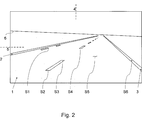
Eine Repräsentation der durch das Kamerabild wiedergegebenen Szene in Vogelperspektive zeigt
Die Erstellung dieser Repräsentation der durch das Kamerabild wiedergegebenen Szene in Vogelperspektive (birdview bzw. top down view) mit Markierungen und Signaturen (S1–S6) in Weltkoordinaten kann aus den Bildkoordinaten mit einer Schrittweite von z. B. 5 cm erfolgen durch eine Rückprojektion, die aus dem Abbildungsmodell der Kamera (
Die Signaturen (S1–S6) auf der Fahrbahnoberfläche werden aus dieser Repräsentation extrahiert. Der Abstand (d) einer Signatur (S1–S6) zur Kamera (
Die Position dieser Signatur (S1–S6) in Weltkoordinaten wird für einen späteren Zeitpunkt unter Berücksichtigung der Eigengeschwindigkeit (v) des Fahrzeuges prädiziert. Der spätere Zeitpunkt Δt wird dabei so gewählt, dass zu diesem späteren Zeitpunkt Δt ein darauffolgendes Bild mit der Kamera (
Eine Prädiktion zu einem Zeitpunkt Δt für eine Signatur (S1–S6), deren Abstand zur Kamera (
Der tatsächliche Abstand (d_meas) dieser Signatur (S1–S6) in Weltkoordinaten wird aus der entsprechenden Repräsentation des zu dem späteren Zeitpunkt dt aufgenommenen Bildes gemessen.The actual distance (d_meas) of this signature (S1-S6) in world coordinates is measured from the corresponding representation of the image taken at the later time dt.
Das Verhältnis von gemessenem zu prädiziertem Signaturabstand wird ermittelt: d_meas/d_est.The ratio of measured to predicted signature spacing is determined: d_meas / d_est.
Auf diese Weise können gemäß einer weiteren Ausführungsform so lange Signaturen in der linken (S1–S3) und in der rechten (S4–S6) Bildhälfte analysiert werden, bis eine ausreichende Zahl N an Prädiktionen und Messungen (z. B. N = 10 oder N = 50) von Signaturabstandsänderungen zwischen jeweils zwei aufeinanderfolgenden Bildern für die linke (N_links > N) und für die rechte (N_rechts > N) Bildhälfte durchgeführt wurde. Das Verhältnis der prädizierten zu gemessenen Signaturabstände wird für die linke und die rechte Bildhälfte gemittelt (d_meas_links/d_est und d_meas_rechts/d_est).In this way, according to another embodiment, signatures in the left (S1-S3) and the right (S4-S6) half of the image can be analyzed until a sufficient number N of predictions and measurements (eg N = 10 or N = 50) of signature pitch changes between every two consecutive pictures for the left (N_links> N) and for the right (N_right> N) picture half. The ratio of the predicted to measured signature distances is averaged for the left and the right half of the screen (d_meas_links / d_est and d_meas_right / d_est).
Dann kann eine Aktualisierung des geschätzten Rollwinkelwerts folgendermaßen durchgeführt werden:
- • Falls d_meas_links/d_est > d_meas_rechts/d_est, wird der Rollwinkel um einen Korrekturwinkel erhöht.
- • Falls d_meas_links/d_est < d_meas_rechts/d_est, wird der Rollwinkel um einen Korrekturwinkel verringert.
- • Andernfalls wird der Rollwinkel beibehalten.
- • If d_meas_links / d_est> d_meas_right / d_est, the roll angle is increased by a correction angle.
- • If d_meas_links / d_est <d_meas_right / d_est, the roll angle is reduced by a correction angle.
- Otherwise, the roll angle is retained.
Der Korrekturwinkel kann einen vorgegebenen konstanten Wert (z. B. 0.05° oder 0.1°) betragen, der die Auflösung der Rollwinkelschätzung bestimmt, oder der Korrekturwinkel kann einen Wert annehmen, der proportional zum Betrag von (d_meas_links/d_est – d_meas_rechts/d_est) ist.The correction angle may be a predetermined constant value (eg, 0.05 ° or 0.1 °) that determines the resolution of the roll angle estimate, or the correction angle may assume a value that is proportional to the amount of (d_meas_links / d_est - d_meas_right / d_est) ,
Durch die Bildung des Verhältnisses von gemessenem (d_meas) zu prädiziertem (d_est) Signaturabstand werden die Einflüsse einer Geschwindigkeitsänderung des Fahrzeugs berücksichtigt.The formation of the ratio of measured (d_meas) to predicted (d_est) signature spacing takes into account the influences of a speed change of the vehicle.
BezugszeichenlisteLIST OF REFERENCE NUMBERS
- 11
- Fahrbahnroadway
- 22
- Linke durchgehende FahrbahnmarkierungLeft continuous road marking
- 33
- Rechte durchgehende FahrbahnmarkierungRight continuous road markings
- 44
- Horizontale BildmitteHorizontal picture center
- 55
- Vertikale BildmitteVertical picture center
- 66
- Horizonthorizon
- 77
- Fahrzeugvehicle
- 88th
- Kameracamera
- S1–S6S1-S6
-
Signatur 1 bis 6
Signature 1 to 6 - dd
- Abstand Signatur zu Kamera in Richtung der Fahrzeuglängsachse in WeltkoordinatenDistance signature to camera in the direction of the vehicle's longitudinal axis in world coordinates
- vv
- Fahrzeuggeschwindigkeitvehicle speed
ZITATE ENTHALTEN IN DER BESCHREIBUNG QUOTES INCLUDE IN THE DESCRIPTION
Diese Liste der vom Anmelder aufgeführten Dokumente wurde automatisiert erzeugt und ist ausschließlich zur besseren Information des Lesers aufgenommen. Die Liste ist nicht Bestandteil der deutschen Patent- bzw. Gebrauchsmusteranmeldung. Das DPMA übernimmt keinerlei Haftung für etwaige Fehler oder Auslassungen.This list of the documents listed by the applicant has been generated automatically and is included solely for the better information of the reader. The list is not part of the German patent or utility model application. The DPMA assumes no liability for any errors or omissions.
Zitierte PatentliteraturCited patent literature
- DE 102006018978 A1 [0006] DE 102006018978 A1 [0006]
Claims (8)
Priority Applications (8)
| Application Number | Priority Date | Filing Date | Title |
|---|---|---|---|
| DE102009055776A DE102009055776A1 (en) | 2009-11-25 | 2009-11-25 | Method for estimating the roll angle in a moving vehicle |
| JP2012541317A JP2013512150A (en) | 2009-11-25 | 2010-11-16 | Method for evaluating roll angle in a traveling vehicle |
| CN201080053510.5A CN102648115B (en) | 2009-11-25 | 2010-11-16 | For estimating the method for angle of roll in the automobile travelled |
| KR1020127016556A KR101729912B1 (en) | 2009-11-25 | 2010-11-16 | Method for estimating the roll angle in a travelling vehicle |
| EP10801117.2A EP2504209B1 (en) | 2009-11-25 | 2010-11-16 | Method to estimate the roll angle in a car |
| DE112010003422T DE112010003422A5 (en) | 2009-11-25 | 2010-11-16 | Method for estimating the roll angle in a moving vehicle |
| US13/511,733 US8824741B2 (en) | 2009-11-25 | 2010-11-16 | Method for estimating the roll angle in a travelling vehicle |
| PCT/DE2010/001332 WO2011063785A1 (en) | 2009-11-25 | 2010-11-16 | Method for estimating the roll angle in a travelling vehicle |
Applications Claiming Priority (1)
| Application Number | Priority Date | Filing Date | Title |
|---|---|---|---|
| DE102009055776A DE102009055776A1 (en) | 2009-11-25 | 2009-11-25 | Method for estimating the roll angle in a moving vehicle |
Publications (1)
| Publication Number | Publication Date |
|---|---|
| DE102009055776A1 true DE102009055776A1 (en) | 2011-05-26 |
Family
ID=43502100
Family Applications (2)
| Application Number | Title | Priority Date | Filing Date |
|---|---|---|---|
| DE102009055776A Withdrawn DE102009055776A1 (en) | 2009-11-25 | 2009-11-25 | Method for estimating the roll angle in a moving vehicle |
| DE112010003422T Withdrawn DE112010003422A5 (en) | 2009-11-25 | 2010-11-16 | Method for estimating the roll angle in a moving vehicle |
Family Applications After (1)
| Application Number | Title | Priority Date | Filing Date |
|---|---|---|---|
| DE112010003422T Withdrawn DE112010003422A5 (en) | 2009-11-25 | 2010-11-16 | Method for estimating the roll angle in a moving vehicle |
Country Status (7)
| Country | Link |
|---|---|
| US (1) | US8824741B2 (en) |
| EP (1) | EP2504209B1 (en) |
| JP (1) | JP2013512150A (en) |
| KR (1) | KR101729912B1 (en) |
| CN (1) | CN102648115B (en) |
| DE (2) | DE102009055776A1 (en) |
| WO (1) | WO2011063785A1 (en) |
Cited By (3)
| Publication number | Priority date | Publication date | Assignee | Title |
|---|---|---|---|---|
| WO2013079057A1 (en) * | 2011-11-29 | 2013-06-06 | Conti Temic Microelectronic Gmbh | Method for determining a risk of overturning of a vehicle |
| EP3159195A1 (en) * | 2015-10-21 | 2017-04-26 | Continental Automotive GmbH | Driver assistance device for a vehicle and method to tare a skew of the vehicle |
| EP3351450A1 (en) * | 2014-05-27 | 2018-07-25 | MAN Truck & Bus AG | Method and driver assistance system for determining dynamic driving states in a commercial vehicle |
Families Citing this family (15)
| Publication number | Priority date | Publication date | Assignee | Title |
|---|---|---|---|---|
| JP5883275B2 (en) * | 2011-11-18 | 2016-03-09 | 東芝アルパイン・オートモティブテクノロジー株式会社 | In-vehicle camera calibration device |
| DE102012108862A1 (en) | 2012-09-20 | 2014-05-28 | Continental Teves Ag & Co. Ohg | Method for calibrating several environment sensors in a vehicle |
| DE102015202115A1 (en) * | 2015-02-06 | 2016-08-11 | Robert Bosch Gmbh | Method for determining the angle of inclination of a two-wheeler |
| FR3036180B1 (en) * | 2015-05-11 | 2018-08-10 | Valeo Schalter Und Sensoren Gmbh | METHOD FOR DETERMINING THE PLATE OF A MOTOR VEHICLE |
| JP6413974B2 (en) * | 2015-08-05 | 2018-10-31 | 株式会社デンソー | Calibration apparatus, calibration method, and program |
| US10235817B2 (en) * | 2015-09-01 | 2019-03-19 | Ford Global Technologies, Llc | Motion compensation for on-board vehicle sensors |
| US10290119B2 (en) * | 2016-09-15 | 2019-05-14 | Sportsmedia Technology Corporation | Multi view camera registration |
| CN106585546B (en) * | 2016-09-30 | 2019-03-22 | 张家港长安大学汽车工程研究院 | A kind of vehicle side turning early warning system |
| DE102016220559A1 (en) | 2016-10-20 | 2018-04-26 | Conti Temic Microelectronic Gmbh | Method and system for determining a roll angle of a two-wheeler during cornering |
| CN107395954B (en) * | 2017-06-12 | 2020-08-07 | 海信(山东)冰箱有限公司 | Refrigerator positioning shooting method and system |
| CN109086650B (en) * | 2017-06-14 | 2022-04-12 | 现代摩比斯株式会社 | Calibration method and calibration apparatus |
| WO2019140792A1 (en) * | 2018-01-17 | 2019-07-25 | 上海禾赛光电科技有限公司 | Detection apparatus and parameter adjustment method thereof |
| KR102553053B1 (en) | 2018-12-28 | 2023-07-11 | 삼성전자주식회사 | Electronic device for detecting risk around vehicle and method for controlling thereof |
| US11659261B2 (en) * | 2021-08-19 | 2023-05-23 | Ford Global Technologies, Llc | Vehicle optical sensor motion correction |
| CN116381632B (en) * | 2023-06-05 | 2023-08-18 | 南京隼眼电子科技有限公司 | Self-calibration method and device for radar roll angle and storage medium |
Citations (3)
| Publication number | Priority date | Publication date | Assignee | Title |
|---|---|---|---|---|
| DE10204128A1 (en) * | 2002-02-01 | 2003-08-07 | Bosch Gmbh Robert | Rollover detection device |
| DE102004048400A1 (en) * | 2004-10-01 | 2006-04-06 | Robert Bosch Gmbh | Method for detecting an optical structure |
| DE102006018978A1 (en) | 2006-04-25 | 2007-11-08 | Adc Automotive Distance Control Systems Gmbh | Motor vehicle roll angle determining method, involves determining yaw rate or correlated size, and vehicle speed, and determining roll angle of motor vehicle using yaw rate or correlated size and specific vehicle roll spring rigidity |
Family Cites Families (10)
| Publication number | Priority date | Publication date | Assignee | Title |
|---|---|---|---|---|
| US5638116A (en) * | 1993-09-08 | 1997-06-10 | Sumitomo Electric Industries, Ltd. | Object recognition apparatus and method |
| JP2000353300A (en) | 1999-06-11 | 2000-12-19 | Honda Motor Co Ltd | Object recognizing device |
| JP3995846B2 (en) * | 1999-09-24 | 2007-10-24 | 本田技研工業株式会社 | Object recognition device |
| JP4803927B2 (en) | 2001-09-13 | 2011-10-26 | 富士重工業株式会社 | Distance correction apparatus and distance correction method for monitoring system |
| JP3969984B2 (en) * | 2001-09-25 | 2007-09-05 | ダイハツ工業株式会社 | Recognition method for moving objects |
| JP4228865B2 (en) * | 2003-09-30 | 2009-02-25 | 三菱ふそうトラック・バス株式会社 | Rollover suppression control device for vehicle |
| JP4296076B2 (en) * | 2003-11-13 | 2009-07-15 | 三菱電機株式会社 | Driving lane recognition device |
| JP4297501B2 (en) | 2004-08-11 | 2009-07-15 | 国立大学法人東京工業大学 | Moving object periphery monitoring device |
| DE102006061483B4 (en) * | 2006-02-22 | 2024-01-25 | Continental Automotive Technologies GmbH | Method and device for determining the roll angle of a motorcycle |
| JP4321554B2 (en) * | 2006-06-23 | 2009-08-26 | トヨタ自動車株式会社 | Attitude angle detection device and attitude angle detection method |
-
2009
- 2009-11-25 DE DE102009055776A patent/DE102009055776A1/en not_active Withdrawn
-
2010
- 2010-11-16 JP JP2012541317A patent/JP2013512150A/en active Pending
- 2010-11-16 EP EP10801117.2A patent/EP2504209B1/en active Active
- 2010-11-16 DE DE112010003422T patent/DE112010003422A5/en not_active Withdrawn
- 2010-11-16 US US13/511,733 patent/US8824741B2/en active Active
- 2010-11-16 KR KR1020127016556A patent/KR101729912B1/en active IP Right Grant
- 2010-11-16 CN CN201080053510.5A patent/CN102648115B/en active Active
- 2010-11-16 WO PCT/DE2010/001332 patent/WO2011063785A1/en active Application Filing
Patent Citations (3)
| Publication number | Priority date | Publication date | Assignee | Title |
|---|---|---|---|---|
| DE10204128A1 (en) * | 2002-02-01 | 2003-08-07 | Bosch Gmbh Robert | Rollover detection device |
| DE102004048400A1 (en) * | 2004-10-01 | 2006-04-06 | Robert Bosch Gmbh | Method for detecting an optical structure |
| DE102006018978A1 (en) | 2006-04-25 | 2007-11-08 | Adc Automotive Distance Control Systems Gmbh | Motor vehicle roll angle determining method, involves determining yaw rate or correlated size, and vehicle speed, and determining roll angle of motor vehicle using yaw rate or correlated size and specific vehicle roll spring rigidity |
Cited By (4)
| Publication number | Priority date | Publication date | Assignee | Title |
|---|---|---|---|---|
| WO2013079057A1 (en) * | 2011-11-29 | 2013-06-06 | Conti Temic Microelectronic Gmbh | Method for determining a risk of overturning of a vehicle |
| US9187051B2 (en) | 2011-11-29 | 2015-11-17 | Conti Temic Microelectronic Gmbh | Method for detecting an imminent rollover of a vehicle |
| EP3351450A1 (en) * | 2014-05-27 | 2018-07-25 | MAN Truck & Bus AG | Method and driver assistance system for determining dynamic driving states in a commercial vehicle |
| EP3159195A1 (en) * | 2015-10-21 | 2017-04-26 | Continental Automotive GmbH | Driver assistance device for a vehicle and method to tare a skew of the vehicle |
Also Published As
| Publication number | Publication date |
|---|---|
| JP2013512150A (en) | 2013-04-11 |
| EP2504209A1 (en) | 2012-10-03 |
| DE112010003422A5 (en) | 2012-06-06 |
| WO2011063785A1 (en) | 2011-06-03 |
| US20120281881A1 (en) | 2012-11-08 |
| EP2504209B1 (en) | 2017-01-11 |
| CN102648115A (en) | 2012-08-22 |
| CN102648115B (en) | 2015-11-25 |
| KR20130004895A (en) | 2013-01-14 |
| KR101729912B1 (en) | 2017-04-25 |
| US8824741B2 (en) | 2014-09-02 |
Similar Documents
| Publication | Publication Date | Title |
|---|---|---|
| EP2504209B1 (en) | Method to estimate the roll angle in a car | |
| DE102016223422B4 (en) | Method for automatically determining extrinsic parameters of a vehicle camera | |
| DE102013221696A1 (en) | Method and device for determining a height profile of a road ahead of a vehicle | |
| DE112018001569T5 (en) | Information processing device and information processing system | |
| EP2189349A2 (en) | Method and device for compensating a roll angle | |
| EP1710749A1 (en) | Correction of yaw angle measuring errors for driving lane detection sensors | |
| EP3046076B1 (en) | Method for calibrating an image capturing device | |
| DE102017109445A1 (en) | Calibration of a vehicle camera device in the vehicle longitudinal direction or vehicle transverse direction | |
| EP3488607A1 (en) | Camera device for capturing a surrounding area of a driver's own vehicle and method for providing a driver assistance function | |
| DE102018204451A1 (en) | Method and device for auto-calibration of a vehicle camera system | |
| DE102020210515A1 (en) | Method for checking detected changes for an environment model of a digital environment map | |
| DE102010049216A1 (en) | Method for operating camera i.e. stereo camera, arranged at car, involves detecting distance of object via image evaluation, and calibrating camera when distance determined by sensing unit deviates from distance determined by evaluation | |
| EP2715666A1 (en) | Method for determining a pitching movement in a camera installed in a vehicle, and method for controlling a light emission from at least one headlamp on a vehicle | |
| DE102008026876A1 (en) | Stereo camera system and method for determining at least one calibration error of a stereo camera system | |
| DE102019112279A1 (en) | METHOD AND DEVICE FOR DIAGONAL TRACK DETECTION | |
| WO2009086970A1 (en) | Method and device for image detection for motor vehicles | |
| WO2019162327A2 (en) | Method for determining a distance between a motor vehicle and an object | |
| EP2199951A2 (en) | Device and method of determining a vanishing point | |
| DE102010009620B4 (en) | Method and device for detecting at least one obstacle in a vehicle environment | |
| DE102012008030A1 (en) | Method for detecting road edge for vehicle, involves detecting road edge as a function of straight line which is designed depending on feature points | |
| DE102019102561A1 (en) | Process for recognizing a plaster marking | |
| DE102018212871A1 (en) | Device and method for camera calibration | |
| DE102022204776B3 (en) | Method for locating a vehicle within a SAR image | |
| WO2022161772A1 (en) | Method and device for determining a detection range of a sensor of a motor vehicle | |
| DE102016117500A1 (en) | Calibration of a camera of a vehicle |
Legal Events
| Date | Code | Title | Description |
|---|---|---|---|
| OM8 | Search report available as to paragraph 43 lit. 1 sentence 1 patent law | ||
| R118 | Application deemed withdrawn due to claim for domestic priority |
Effective date: 20120328 |