EP2517549A1 - Assembly and method for detecting the quantity of plants on a field - Google Patents
Assembly and method for detecting the quantity of plants on a field Download PDFInfo
- Publication number
- EP2517549A1 EP2517549A1 EP12161450A EP12161450A EP2517549A1 EP 2517549 A1 EP2517549 A1 EP 2517549A1 EP 12161450 A EP12161450 A EP 12161450A EP 12161450 A EP12161450 A EP 12161450A EP 2517549 A1 EP2517549 A1 EP 2517549A1
- Authority
- EP
- European Patent Office
- Prior art keywords
- plants
- waves
- reflected
- receiver
- transmitter
- Prior art date
- Legal status (The legal status is an assumption and is not a legal conclusion. Google has not performed a legal analysis and makes no representation as to the accuracy of the status listed.)
- Granted
Links
- 238000000034 method Methods 0.000 title claims abstract description 6
- 238000011156 evaluation Methods 0.000 claims description 33
- 238000003306 harvesting Methods 0.000 claims description 12
- 238000005259 measurement Methods 0.000 claims description 8
- 230000000149 penetrating effect Effects 0.000 abstract 1
- 241000196324 Embryophyta Species 0.000 description 104
- 238000004140 cleaning Methods 0.000 description 9
- 239000002689 soil Substances 0.000 description 5
- 239000010902 straw Substances 0.000 description 5
- 238000001514 detection method Methods 0.000 description 4
- 241001124569 Lycaenidae Species 0.000 description 3
- 238000002592 echocardiography Methods 0.000 description 3
- 239000000463 material Substances 0.000 description 3
- 230000010354 integration Effects 0.000 description 2
- 230000005855 radiation Effects 0.000 description 2
- 238000012360 testing method Methods 0.000 description 2
- 241000251169 Alopias vulpinus Species 0.000 description 1
- 241001464837 Viridiplantae Species 0.000 description 1
- 230000003466 anti-cipated effect Effects 0.000 description 1
- 230000000454 anti-cipatory effect Effects 0.000 description 1
- 238000002485 combustion reaction Methods 0.000 description 1
- 230000001627 detrimental effect Effects 0.000 description 1
- 238000009313 farming Methods 0.000 description 1
- 239000004459 forage Substances 0.000 description 1
- 239000012535 impurity Substances 0.000 description 1
- 239000000203 mixture Substances 0.000 description 1
- 230000002265 prevention Effects 0.000 description 1
- 238000012545 processing Methods 0.000 description 1
- 238000003860 storage Methods 0.000 description 1
- 230000032258 transport Effects 0.000 description 1
Images
Classifications
-
- A—HUMAN NECESSITIES
- A01—AGRICULTURE; FORESTRY; ANIMAL HUSBANDRY; HUNTING; TRAPPING; FISHING
- A01D—HARVESTING; MOWING
- A01D41/00—Combines, i.e. harvesters or mowers combined with threshing devices
- A01D41/12—Details of combines
- A01D41/127—Control or measuring arrangements specially adapted for combines
- A01D41/1274—Control or measuring arrangements specially adapted for combines for drives
-
- A—HUMAN NECESSITIES
- A01—AGRICULTURE; FORESTRY; ANIMAL HUSBANDRY; HUNTING; TRAPPING; FISHING
- A01D—HARVESTING; MOWING
- A01D41/00—Combines, i.e. harvesters or mowers combined with threshing devices
- A01D41/12—Details of combines
- A01D41/14—Mowing tables
- A01D41/141—Automatic header control
-
- A—HUMAN NECESSITIES
- A01—AGRICULTURE; FORESTRY; ANIMAL HUSBANDRY; HUNTING; TRAPPING; FISHING
- A01D—HARVESTING; MOWING
- A01D43/00—Mowers combined with apparatus performing additional operations while mowing
- A01D43/08—Mowers combined with apparatus performing additional operations while mowing with means for cutting up the mown crop, e.g. forage harvesters
- A01D43/085—Control or measuring arrangements specially adapted therefor
Definitions
- the throughput is useful for purposes of automatic adjustment of Gutcroft- and / or Gutbearbeitungs wornen. Good throughput is often measured for purposes of site-specific management. Furthermore, on the basis of the measured material throughput, the advancing speed of the harvesting machine in a field can be adjusted by a corresponding control in such a way that a desired material throughput is achieved which, for example, corresponds to an optimum utilization of the harvesting machine. It is customary to determine the throughput through corresponding sensors in the harvester.
- the regarded as generic DE 10 2008 043 716 A1 describes a device for detecting the plant density of plants) in a field with a transmitter that emits electromagnetic waves in the visible or near-infrared region of the machine obliquely forward and down to a present in front of the machine plant stock and a working and / or angle resolution Receiver that receives waves reflected from the plants of the plant population and / or from the ground.
- An evaluation device determines the transit time of the waves of the transmitter to the receiver at different points along a direction transverse to the forward direction measuring direction and determines the stock density of the plants based on the variation of the detected transit times.
- the object underlying the invention is seen to provide an improved apparatus and method for detecting the amount of plants on a field.
- An arrangement for detecting the volume of plants in a field comprises a first transmitter, which in operation emits first electromagnetic waves in the visible or infrared range (in particular laser beams) onto a plant stock, a first receiver which reflects for the plants or from the ground originally coming from the transmitter first waves is sensitive, and an electronic evaluation device.
- the transmitter (or its waves) and the receiver in a conventional manner are moved or pivoted together stepwise or continuously along a measuring direction or only one of them.
- the evaluation device has information as to which location or at which angle a signal generated by the first receiver is to be assigned.
- the plants may, for example, be present as standing, to be harvested stock or as a swath on the ground.
- the evaluation device determines the transit time of the waves reaching from the transmitter to the receiver, which contains information about the distance of the reflection point from the transmitter and receiver on the basis of the known, fixed speed of light. Such distance values are determined for different points which lie next to one another along the measuring direction, ie. H. stored for further evaluation in a memory.
- the measuring direction usually extends transversely to a forward direction of movement of the device and at least approximately parallel to the ground.
- an at least one-dimensional, so-called distance image is present in the evaluation device which contains the detected distances of the reflection points in the measuring direction in a position-resolved or angle-resolved manner.
- a field lying or standing plants are closer to the device than the ground.
- a first height profile is determined that reflects the heights of the tops of the plants where the first waves were reflected along the direction of measurement. At the points where there are no plants, the first height profile corresponds to the contour of the soil. The first height profile is first saved.
- the waves are almost or only reflected by the plants due to the high density of the plant population.
- the durations of the waves in the Measuring direction are then relatively homogeneous, ie they only vary slightly along the measuring direction. If the plant population is relatively thin, however, a certain proportion of the waves penetrate to the ground and is reflected by it. However, other waves are reflected by more or less distant from the transmitter and receiver standing plants. There are then - due to the gaps in the plant population - therefore a greater variation in the maturity of the waves in the direction of measurement.
- the evaluation device determines the density of the plants on the basis of the differences (ie the variation or the scattering measure) of the transit times of the detected signals in the measuring direction.
- the standard deviation of the transit times can be detected, although any other statistical variables can also be detected, such as an average absolute deviation or a span (greatest difference between the transit times or distances).
- the relationship between the variation of maturity and plant density may be different for different plant species and especially plant heights. Therefore, calibration tables, formulas or the like based on previously performed field trials may be used to calculate the plant density based on the variation of the transit times. Plant density indicates what proportion of the vertical area occupied by the plants in front of the harvester is actually attributable to the plants.
- the second transmitter is provided which emits second electromagnetic waves to the plant population during operation.
- These second waves lie in a wavelength range which penetrates the plant population to a sufficiently large extent and is only reflected by the ground.
- a wavelength range is for example the radar wave range, z. B. around the 24 GHz.
- a second receiver is sensitive to the second waves and thus receives the second waves reflected from the ground.
- the evaluation device determines at different points along the measuring direction in each case a second transit time of the reflected second waves of the second transmitter to the second receiver, wherein also the known or detected via suitable sensors geometry of the second transmitter and second receiver (for example mounting height and Abstrahl- and / or Receiving direction) is taken into account.
- These second runtimes enable the creation of a second height profile, which reproduces the contour of the soil below the plants along the measuring direction.
- the evaluation device determines the heights of the plants using the first height profile and the second height profile.
- the plant heights are then multiplied by the density of the plants and integrated over the measuring direction (or vice versa) to the amount the plants in the form of the occupied by the plants vertical cross-sectional area to determine.
- the quantity of plants is understood to mean any measured quantity which relates to the volume of the plants and / or the vertical cross-sectional area occupied by the plants.
- the density of the plant population can also be determined from the transit times of second waves that are reflected by plants.
- the plants acted upon by the second waves provide an echo which lies temporally in front of the second waves reflected from the ground and whose intensity and / or transit time differences occurring along the measuring direction likewise contain information about the density of the plants. This information is preferably evaluated by the evaluation device and taken into account together with the determined on the basis of the transit time differences of the first waves density of the plants in the determination of the amount of plants.
- the mentioned second waves reflected by the plants also contain information about the mass density of the plants, which can thus be determined by the evaluation device on the basis of the intensities and / or propagation times of the second waves.
- the intensities of the first waves can be used by the evaluation device for determining the mass density of the plants. On the basis of the mass density (in units of kilograms per cubic meter o. The like.) In turn, the mass of plants can be determined.
- the evaluation device is, as stated above, suitable for detecting inventory limits. It can thus be connected to a steering device and automatically lead a harvester along an inventory edge.
- On the basis of the anticipated stock density can be determined at a known width of the crop receptacle, the expected utilization of the harvester and / or leading to a desired utilization propulsion speed.
- the measurement is expediently carried out at a distance in front of a harvesting machine, so that a timely adjustment of the driving speed becomes possible in the case of plant stock density changes. This increases ride comfort and avoids critical situations in which the machine tends to plug.
- the conveying and separating processes in a harvester can be adapted in good time to the upcoming throughputs, so that the harvest result improves.
- the of the Evaluation set provided quantity values can thus serve to adjust the speed of a Gutfordshire coupled (for example, a feeder) or parameters of crop processing equipment (eg threshing drum gap, threshing drum speed).
- the quantity values can also be used for the geo-referenced collection of crop quantities for purposes of site-specific management.
- the present invention also makes it possible to take into account the moisture content of the harvested crop based on the data from the second sensor, because dry crops are easier to thresh and separate than moist crops.
- the throughput can thus be corrected on the basis of the humidity (or the speed is corrected directly on the basis of the humidity).
- the input variable of the speed control can therefore be, for example, a load corrected by the moisture or a load determined from the moisture-corrected throughput of the cleaning or a loss of the cleaning determined from the moisture-corrected throughput.
- the loss of cleaning can be calibrated with absolute loss information that can be obtained using suitable sensors or loss test shells.
- the output signals of the evaluation device contain information about the height of the stock and the ground in front of the harvester, which can be used for automatic adjustment of Ernteguta dressed, at a cutting unit, for example, the reel height, speed and / or position in the forward direction. Also lying plants (storage grain) can be detected in this way, so that the Ernteguting worn as mentioned can be adjusted accordingly in order to accommodate these plants optimally.
- the second height profile allows an automatic, anticipatory adjustment of the height of the Ernteguta planted above the ground and thus the cutting height.
- first and second height profile (depending on the geometry of the transmitter and receiver) are usually recorded at different distances in front of the transmitters and receivers, it may be advisable to use the altitude profile taken earlier in time or further forward (here the rule about the second height profile) to temporarily store to determine the vertical distance to a vertically as possible overlying, later recorded height profile and thus the plant height as accurately as possible.
- the device according to the invention can be used, in particular, for self-propelled or vehicle-mounted or attached harvesting machines, For example, combine harvesters, balers or forage harvesters.
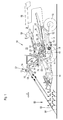
- FIG. 1 shows a harvesting machine in the form of a self-propelled combine harvester 10 with a frame 12 which is supported on the ground and driven by driven front wheels 14 and steerable rear wheels 16 on the ground.
- the wheels 14 are rotated by means not shown drive means in rotation to the combine 10 z. B. to move over a field to be harvested.
- directional details such as front and rear, refer to the direction of travel V of the combine harvester 10 in the harvesting operation.
- a crop gathering device 18 is detachably connected in the form of a cutter to harvest harvested crops in the form of crops or other threshable culottes from the field and feed them up and down by a feeder 20 to a multi-drum threshing unit.
- a threshing cylinder 22 arranged one behind the other - a threshing cylinder 22, a stripping drum 24, a superseding working conveyor drum 26, a Tangentialseparator 28 and a turning drum 30 includes.
- Downstream of the turning drum 30 is a straw shaker 32.
- the threshing drum 22 is surrounded by a concave 34 in its lower and rear area.
- a finger rake 38 is arranged below the conveyor drum 26.
- the mixture passing through the threshing concave 34, the separating basket 36 and the straw shakers 32, containing grains and impurities passes through the conveying bottoms 40, 42 into a Cleaning device 46.
- Grain cleaned by the cleaning device 46 is fed by means of a grain screw 48 to an elevator, not shown, which transports it into a grain tank 50.
- a tailing auger 52 returns unmanaged ear parts through another elevator, not shown, back into the threshing process.
- the chaff may be ejected at the rear of the screen by a rotating chaff spreader, or it may be discharged through a straw chopper (not shown) disposed downstream of the straw walker 32.
- the cleaned grain from the grain tank 50 may be unloaded by a discharge system with cross augers 54 and a discharge conveyor 56.
- the systems mentioned are driven by means of an internal combustion engine 58 and controlled and controlled by an operator from a driver's cab 60.
- the various devices for threshing, conveying, cleaning and separating are located within the frame 12. Outside the frame 12 is an outer shell, which is largely hinged.
- the multi-drum thresher shown here is only one embodiment. It could also be replaced by a single transverse threshing drum and a downstream separating device with a straw walker or one or more separating rotors or a threshing and separating device operating in the axial flow.
- a measuring device 62 is arranged below the roof, which is connected to an evaluation device 76.
- the measuring device 62 could also be attached to the Erntegutbergungs Surprise 18.
- the evaluation device 76 is connected to a speed setting device 78 (for example a swashplate adjusting device of a hydraulic pump, which is connected in a hydraulic fluid-conducting manner to a hydraulic motor that drives the wheels 14), which is set up to set the forwarding speed of the harvesting machine 10.
- the measuring device 62 is composed of a first transmitter 64, a first receiver 66, a second transmitter 68 and a second receiver 70, which are rotatable together by a pivot drive 74 about an approximately vertical, slightly forwardly inclined axis 72.
- electromagnetic waves emitted by the transmitters 64, 68 sweep one ahead of the range of measurement in front of the combine 10 by swiveling the transmitters 64, 68 and receivers 66, 70 (or merely their radiating and / or receiving elements) about the axis 72 , Thereby, the field 80 with the plants standing thereon 82 along a measuring direction, which is in a circular arc in front of extends the combine harvester 10, successively overlined.
- the first transmitter 64 emits electromagnetic first waves in the form of light in the (near) infrared or visible wave range, while the first receiver 66 is sensitive only to this light. Due to the chosen wavelength, the light is reflected by the plants 82 when it hits them. On the other hand, when the light hits the ground 84 between plants (eg in thin or missing stands), it is also reflected off the ground.
- the first transmitter 64 preferably comprises a laser for generating the light.
- the second transmitter 68 emits electromagnetic second waves in the micro or radar wave range, while the second receiver 70 is sensitive only to these waves.
- the wavelength is chosen such that most of the second waves penetrate the plants and are only reflected by the ground 84. A smaller proportion of the second waves is also reflected by the plants 82.
- the electromagnetic waves emitted by the transmitters 64, 68 reach the ground 84 at a distance of a few meters (for example 10 m) in the direction of travel of the combine 10 in front of the crop gathering device 18.
- the waves radiated by the transmitters 64, 68 can be modulated in amplitude or otherwise be to improve the signal-to-noise ratio.
- the evaluation device 76 accomplishes a detection of the distance between the measuring device 62 and the point at which the waves were respectively reflected.
- the pivot drive 74 can be designed as a servo or stepper motor and pivots the measuring device 62 (or only their elements radiating and / or receiving elements) continuously or stepwise by an angular range of for example 30 ° about the axis 72 back and forth.
- the evaluation device 76 is set up for each pivot angle of the measuring device 62 to detect the respective angle about the axis 72 and the transit time of the shaft or the distance of the receiver 66, 70 and transmitter 64, 68 from the reflection point. Subsequently, the pivot drive 74 is activated and the measuring device 62 is moved to another position.
- the evaluation device 74 has information about the respective angle of the measuring device 62, since it controls the pivot drive 74.
- the angle of the measuring device 62 about the axis 72 defines a measuring direction along which the transit times of the waves of the transmitter 64, 68 to the associated receiver 66, 70 are determined. It extends horizontally and in a circular arc transverse to the forward direction of the harvester 10th
- the signals of the first receiver 66 contain information about the height of the upper ends of the plants 82, because there they are primarily reflected. However, some first waves continue to penetrate further down in thinner stocks, some to the ground 84, and are only reflected there and received by the first receiver 66. In thinner stocks, therefore, the distances detected by the first receiver 66 vary more than in denser stands. These different variations of the distances depending on the population density are evaluated by the evaluation device 74 and used to determine the density of the plant population. Furthermore, the measured values of the second receiver 70 serve to determine a soil profile which, in conjunction with the heights of the tops of the plants 82 detected by the first receiver 66, is used for a more accurate determination of the plant heights, which are also used to determine the amount of plant.
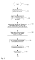
- step 102 the evaluation device 76 causes the pivoting drive 74, with the measuring device 62, a stepwise (or continuous) to sweep a certain angle range in front of the harvester 10.
- the respective swivel angle and distance measured values are stored by the evaluation device 76 in step 104.
- a profile of the plant heights along the measuring direction is calculated.
- the distance values (derived from reflections on tops of plants 82, which can be estimated approximately on the basis of travel time) of the first receiver 66 are first converted into the heights of the tops of the plants 82, which is based on the known geometry (height of the measuring device 62 via the ground 84 and the angle of radiation of the waves relative to the ground).
- the distance values of the second receiver 70 are converted into the heights of the ground 84, which is done on the basis of the known geometry (height of the measuring device 62 above the ground 84 and the angle of radiation of the waves relative to the ground).
- the heights of the soil are subtracted from the heights of the tops of the plants to produce the profile of plant heights.
- the first waves are reflected further ahead than the second waves (cf. FIG. 1 )
- the heights of the ground 84 detected by the second receiver 70 are first to be temporarily stored until exactly vertically superimposed height profiles of the tops of the plants 82 and of the ground 84 are subtracted from each other in the forward direction.
- the densities of the crop are determined.
- pre-echoes picked up by the second receiver 70 are also taken into account, because they are due to reflection of the second waves on the plants 82, which lie in time before the arrival of the second waves reflected at the ground 84 at the second receiver 70.
- These densities of the plant population are unitless and can be measured, for example, in units of percentages. They indicate what proportion of the detected vertical cross-sectional area of the plants 82 enveloped by the plants 82 in front of the measuring device 62 is actually occupied by plants 82.
- the vertical cross-sectional area occupied by plants 82 in front of the harvester 10 is then determined (by multiplying the plant heights by the plant density and integration via the measuring direction or vice versa) in step 110.
- This cross-sectional area has the dimension of a surface and can be converted into a volume by further integration along the forward direction and converted to a volume rate by multiplying by the propulsion rate.
- the mass density of the plants 82 is determined, ie their volume-related mass.
- the intensities of the waves received by the first receiver 66 can be taken into account (green plants generally have a higher density than dry, brown plants, cf. EP 1 271 139 A2 whose contents are incorporated by reference into the present documentation) and / or the intensities of the pre-echoes of the second waves, as described with respect to step 108.
- the rate of the crop 82 picked up by the combine 10 (in units of kg / s) is determined. Since this value is determined in a forward-looking manner, it can be used by the evaluation device 74 by means of the speed setting device 78 for the automatic adjustment of the forward speed of the combine harvester 10. At this point, the moisture of the crop can be taken into account, which can be determined in step 108 on the basis of the signals of the second receiver 70, whose pre-echoes not only on the density of the Plant life, but also depend on the moisture of the plants.
- the throughput (if necessary corrected on the basis of the humidity) can be converted directly into a propulsion speed value, or it (possibly corrected on the basis of the humidity) is first converted into a load of the cleaning, which is used to determine the propulsion speed, or he (possibly corrected by the humidity) is first converted into a loss value of the cleaning, which is used to determine the propulsion speed.
- the loss value can be calibrated by means of suitable sensors that directly detect the losses or a test shell.
- the throughput (especially at constant propulsion rates leading to time varying throughputs) can be used to automatically adjust equipment of the combine 10, such as the threshing drum gap or threshing drum speed, or to adjust the speed of the cleaning fan or screen opening.
- the measured values of the first receiver 66 can also be used for the automatic steering of the combine harvester 10.
- the height profiles of the soil 84 generated with the signals of the second receiver 70 can be used for a predictive, automatic height control of the harvesting device 18.
- Step 114 is followed again by step 102.
- the plant masses detectable by integrating the rates determined at step 114 may be georeferenced for precision farming purposes by means of position signals from a satellite-based positioning system (not shown).
- the present invention is suitable not only for standing plants as described above, but also for plants lying in a swath.
Landscapes
- Life Sciences & Earth Sciences (AREA)
- Environmental Sciences (AREA)
- Investigating Or Analysing Materials By Optical Means (AREA)
- Harvesting Machines For Root Crops (AREA)
Abstract
Description
Die Erfindung betrifft eine Anordnung zur Bestimmung der Menge an Pflanzen auf einem Feld, mit:
- einem ersten Sender, der betreibbar ist, erste elektromagnetische Wellen im sichtbaren oder infraroten Wellenlängenbereich auf einen Pflanzenbestand auf einem Feld abzustrahlen,
- einem ersten Empfänger, der betreibbar ist, von den Pflanzen des Pflanzenbestandes reflektierte erste Wellen zu empfangen,
- und einer Auswertungseinrichtung, die betreibbar ist, an unterschiedlichen Punkten entlang einer Messrichtung jeweils eine erste Laufzeit der reflektierten ersten Wellen des ersten Senders zum ersten Empfänger zu ermitteln und damit ein erstes Höhenprofil der Oberflächen der Pflanzen entlang der Messrichtung zu bestimmen sowie die Dichte der Pflanzen anhand der Unterschiede der erfassten Laufzeiten der reflektierten ersten Wellen des ersten Senders zum ersten Empfänger entlang der Messrichtung zu bestimmen.
- a first transmitter operable to radiate first electromagnetic waves in the visible or infrared wavelength range onto a crop in a field,
- a first receiver operable to receive first waves reflected from the plants of the plant stock,
- and an evaluation device which is operable to determine a first transit time of the reflected first waves of the first transmitter to the first receiver at different points along a measuring direction and thus to determine a first height profile of the surfaces of the plants along the measuring direction and the density of the plants determine the differences of the detected transit times of the reflected first waves of the first transmitter to the first receiver along the measuring direction.
Bei Erntemaschinen ist zu Zwecken einer selbsttätigen Einstellung von Gutförder- und/oder Gutbearbeitungseinrichtungen eine Messung des Gutdurchsatzes sinnvoll. Der Gutdurchsatz wird häufig auch zu Zwecken der teilflächenspezifischen Bewirtschaftung gemessen. Weiterhin kann anhand des gemessenen Gutdurchsatzes die Vortriebsgeschwindigkeit der Erntemaschine auf einem Feld durch eine entsprechende Steuerung derart eingestellt werden, dass ein gewünschter Gutdurchsatz erreicht wird, der beispielsweise einer optimalen Auslastung der Erntemaschine entspricht. Es ist üblich, den Gutdurchsatz durch entsprechende Sensoren in der Erntemaschine zu ermitteln. Da die Messung erst erfolgt, nachdem das Gut von der Erntemaschine aufgenommen wurde, kann eine sprunghafte Änderung des Gutdurchsatzes bei derartigen Sensoren nicht mehr durch eine entsprechende Anpassung der Fahrgeschwindigkeit ausgeglichen werden, was eine Unter- oder Überlastung von Gutbearbeitungseinrichtungen oder sogar Verstopfungen zur Folge haben kann.For harvesters, a measure of the throughput is useful for purposes of automatic adjustment of Gutförder- and / or Gutbearbeitungseinrichtungen. Good throughput is often measured for purposes of site-specific management. Furthermore, on the basis of the measured material throughput, the advancing speed of the harvesting machine in a field can be adjusted by a corresponding control in such a way that a desired material throughput is achieved which, for example, corresponds to an optimum utilization of the harvesting machine. It is customary to determine the throughput through corresponding sensors in the harvester. Since the measurement only takes place after the crop has been picked up by the harvester, a sudden change in the throughput of such sensors can no longer be compensated by a corresponding adjustment of the driving speed, which can result in underloading or overloading of cropping devices or even blockages ,
In der
Die als gattungsbildend angesehene
Die der Erfindung zu Grunde liegende Aufgabe wird darin gesehen, eine verbesserte Vorrichtung und ein Verfahren zur Erfassung der Menge von Pflanzen auf einem Feld bereitzustellen.The object underlying the invention is seen to provide an improved apparatus and method for detecting the amount of plants on a field.
Diese Aufgabe wird erfindungsgemäß durch die Lehre der Patentansprüche 1 und 10 gelöst, wobei in den weiteren Patentansprüchen Merkmale aufgeführt sind, die die Lösung in vorteilhafter Weise weiterentwickeln.This object is achieved by the teaching of
Eine Anordnung zur Erfassung des Volumens von Pflanzen auf einem Feld umfasst einen ersten Sender, der im Betrieb erste elektromagnetische Wellen im sichtbaren oder infraroten Bereich (insbesondere Laserstrahlen) auf einen Pflanzenbestand abstrahlt, einen ersten Empfänger, der für von den Pflanzen bzw. vom Erdboden reflektierte, ursprünglich vom Sender kommende erste Wellen sensitiv ist, und eine elektronische Auswertungseinrichtung. Dabei können der Sender (oder seine Wellen) und der Empfänger in an sich bekannter Weise (s.
Die Auswertungseinrichtung ermittelt die Laufzeit der vom Sender bis zum Empfänger gelangenden Wellen, die aufgrund der bekannten, festen Lichtgeschwindigkeit eine Information über den Abstand des Reflexionspunkts vom Sender und Empfänger enthält. Derartige Abstandswerte werden für unterschiedliche Punkte ermittelt, die nebeneinander entlang der Messrichtung liegen, d. h. zur weiteren Auswertung in einem Speicher abgelegt. Die Messrichtung erstreckt sich in der Regel quer zu einer Vorwärtsbewegungsrichtung der Vorrichtung und zumindest näherungsweise parallel zum Erdboden.The evaluation device determines the transit time of the waves reaching from the transmitter to the receiver, which contains information about the distance of the reflection point from the transmitter and receiver on the basis of the known, fixed speed of light. Such distance values are determined for different points which lie next to one another along the measuring direction, ie. H. stored for further evaluation in a memory. The measuring direction usually extends transversely to a forward direction of movement of the device and at least approximately parallel to the ground.
In der Auswertungseinrichtung ist demnach ein zumindest eindimensionales, so genanntes Entfernungsbild vorhanden, das die erfassten Abstände der Reflexionspunkte in der Messrichtung orts- oder winkelaufgelöst enthält. Auf einem Feld liegende oder stehende Pflanzen befinden sich näher an der Vorrichtung als der Erdboden. Anhand dieses Entfernungsbildes und der bekannten bzw. über geeignete Sensoren erfassten Geometrie des ersten Senders und ersten Empfängers (beispielsweise Anbringungshöhe und Abstrahl- und/oder Empfangsrichtung, vgl.
Falls der Pflanzenbestand relativ dicht ist, werden die Wellen aufgrund der großen Dichte des Pflanzenbestandes fast oder nur von den Pflanzen reflektiert. Die Laufzeiten der Wellen in der Messrichtung sind dann demnach relativ homogen, d. h. sie variieren nur geringfügig entlang der Messrichtung. Falls der Pflanzenbestand hingegen relativ dünn ist, dringt ein gewisser Anteil der Wellen bis zum Erdboden hin durch und wird durch diesen reflektiert. Andere Wellen werden jedoch durch mehr oder weniger weit vom Sender und Empfänger beabstandet stehende Pflanzen reflektiert. Es gibt dann - aufgrund der Lücken im Pflanzenbestand - demnach eine größere Variation in den Laufzeiten der Wellen in der Messrichtung. Die Auswertungseinrichtung determiniert die Dichte der Pflanzen anhand der Unterschiede (d. h. der Variation bzw. dem Streuungsmaß) der Laufzeiten der erfassten Signale in der Messrichtung. Dabei kann insbesondere die Standardabweichung der Laufzeiten erfasst werden, obwohl auch beliebige andere statistische Größen erfassbar sind, wie eine mittlere absolute Abweichung oder eine Spannweite (größter Unterschied zwischen den Laufzeiten bzw. Abständen). Der Zusammenhang zwischen der Variation der Laufzeiten und der Pflanzendichte kann für unterschiedliche Pflanzenarten und insbesondere Pflanzenhöhen unterschiedlich sein. Zur Berechnung der Pflanzendichte basierend auf der Variation der Laufzeiten können deshalb Kalibriertabellen, Formeln oder dergleichen verwendet werden, die auf zuvor durchgeführten Feldversuchen beruhen. Die Pflanzendichte gibt an, welcher Anteil der vertikalen, von den Pflanzen eingenommenen Fläche vor der Erntemaschine tatsächlich den Pflanzen zuordenbar ist.If the plant population is relatively dense, the waves are almost or only reflected by the plants due to the high density of the plant population. The durations of the waves in the Measuring direction are then relatively homogeneous, ie they only vary slightly along the measuring direction. If the plant population is relatively thin, however, a certain proportion of the waves penetrate to the ground and is reflected by it. However, other waves are reflected by more or less distant from the transmitter and receiver standing plants. There are then - due to the gaps in the plant population - therefore a greater variation in the maturity of the waves in the direction of measurement. The evaluation device determines the density of the plants on the basis of the differences (ie the variation or the scattering measure) of the transit times of the detected signals in the measuring direction. In particular, the standard deviation of the transit times can be detected, although any other statistical variables can also be detected, such as an average absolute deviation or a span (greatest difference between the transit times or distances). The relationship between the variation of maturity and plant density may be different for different plant species and especially plant heights. Therefore, calibration tables, formulas or the like based on previously performed field trials may be used to calculate the plant density based on the variation of the transit times. Plant density indicates what proportion of the vertical area occupied by the plants in front of the harvester is actually attributable to the plants.
Weiterhin ist zweiter Sender vorgesehen, der im Betrieb zweite elektromagnetische Wellen auf den Pflanzenbestand abstrahlt. Diese zweiten Wellen liegen in einem Wellenlängenbereich, der zu einem hinreichend großen Anteil den Pflanzenbestand durchdringt und erst vom Erdboden reflektiert wird. Ein derartiger Wellenlängenbereich ist beispielsweise der Radarwellenbereich, z. B. um die 24 GHz. Ein zweiter Empfänger ist für die zweiten Wellen sensitiv und empfängt somit die vom Erdboden reflektierten zweiten Wellen. Die Auswertungseinrichtung ermittelt an unterschiedlichen Punkten entlang der Messrichtung jeweils eine zweite Laufzeit der reflektierten zweiten Wellen des zweiten Senders zum zweiten Empfänger, wobei ebenfalls die bekannte bzw. über geeignete Sensoren erfasste Geometrie des zweiten Senders und zweiten Empfängers (beispielsweise Anbringungshöhe und Abstrahl- und/oder Empfangsrichtung) berücksichtigt wird. Diese zweiten Laufzeiten ermöglichen die Erstellung eines zweiten Höhenprofils, das die Kontur des Erdbodens unterhalb der Pflanzen entlang der Messrichtung wiedergibt.Furthermore, the second transmitter is provided which emits second electromagnetic waves to the plant population during operation. These second waves lie in a wavelength range which penetrates the plant population to a sufficiently large extent and is only reflected by the ground. Such a wavelength range is for example the radar wave range, z. B. around the 24 GHz. A second receiver is sensitive to the second waves and thus receives the second waves reflected from the ground. The evaluation device determines at different points along the measuring direction in each case a second transit time of the reflected second waves of the second transmitter to the second receiver, wherein also the known or detected via suitable sensors geometry of the second transmitter and second receiver (for example mounting height and Abstrahl- and / or Receiving direction) is taken into account. These second runtimes enable the creation of a second height profile, which reproduces the contour of the soil below the plants along the measuring direction.
Die Auswertungseinrichtung bestimmt unter Verwendung des ersten Höhenprofils und des zweiten Höhenprofils die Höhen der Pflanzen. Die Pflanzenhöhen werden dann mit der Dichte der Pflanzen multipliziert und über die Messrichtung integriert (oder umgekehrt), um die Menge der Pflanzen in Form der von den Pflanzen belegten vertikalen Querschnittsfläche zu bestimmen. Im Rahmen des erfindungsgemäßen Gedankens wird unter der Menge der Pflanzen eine beliebige Messgröße verstanden, die sich auf das Volumen der Pflanzen und/oder die von den Pflanzen belegte vertikale Querschnittsfläche bezieht.The evaluation device determines the heights of the plants using the first height profile and the second height profile. The plant heights are then multiplied by the density of the plants and integrated over the measuring direction (or vice versa) to the amount the plants in the form of the occupied by the plants vertical cross-sectional area to determine. Within the scope of the concept according to the invention, the quantity of plants is understood to mean any measured quantity which relates to the volume of the plants and / or the vertical cross-sectional area occupied by the plants.
Auf diese Weise wird eine relativ genaue Erfassung der Menge der Pflanzen ermöglicht.In this way, a relatively accurate detection of the amount of plants is possible.
Die Dichte des Pflanzenbestandes kann auch anhand der Laufzeiten von zweiten Wellen ermittelt werden, die von Pflanzen reflektiert werden. Die von den zweiten Wellen beaufschlagten Pflanzen liefern ein Echo, das zeitlich vor den vom Erdboden reflektierten zweiten Wellen liegt und dessen Intensität und/oder entlang der Messrichtung auftretenden Laufzeitunterschiede ebenfalls eine Information über die Pflanzendichte enthalten. Diese Information wird vorzugsweise von der Auswertungseinrichtung evaluiert und gemeinsam mit der anhand der Laufzeitunterschiede der ersten Wellen festgestellten Dichte der Pflanzen bei der Bestimmung der Pflanzenmenge berücksichtigt.The density of the plant population can also be determined from the transit times of second waves that are reflected by plants. The plants acted upon by the second waves provide an echo which lies temporally in front of the second waves reflected from the ground and whose intensity and / or transit time differences occurring along the measuring direction likewise contain information about the density of the plants. This information is preferably evaluated by the evaluation device and taken into account together with the determined on the basis of the transit time differences of the first waves density of the plants in the determination of the amount of plants.
Die erwähnten, von den Pflanzen reflektierten zweiten Wellen enthalten auch Informationen über die Massendichte der Pflanzen, die somit von der Auswertungseinrichtung anhand der Intensitäten und/oder Laufzeiten der zweiten Wellen ermittelt werden kann. Alternativ oder zusätzlich können die Intensitäten der ersten Wellen durch die Auswertungseinrichtung zur Bestimmung der Massendichte der Pflanzen herangezogen werden. Anhand der Massendichte (in Einheiten von Kilogramm pro Kubikmeter o. dgl.) kann wiederum die Masse der Pflanzen bestimmt werden.The mentioned second waves reflected by the plants also contain information about the mass density of the plants, which can thus be determined by the evaluation device on the basis of the intensities and / or propagation times of the second waves. Alternatively or additionally, the intensities of the first waves can be used by the evaluation device for determining the mass density of the plants. On the basis of the mass density (in units of kilograms per cubic meter o. The like.) In turn, the mass of plants can be determined.
Die Auswertungseinrichtung ist, wie oben dargelegt, zur Erkennung von Bestandsgrenzen geeignet. Sie kann somit mit einer Lenkeinrichtung verbunden sein und eine Erntemaschine selbsttätig entlang einer Bestandskante führen. Anhand der vorausschauend gemessenen Bestandsdichte kann bei bekannter Breite der Gutaufnahmeeinrichtung die zu erwartende Auslastung der Erntemaschine und/oder die zu einer erwünschten Auslastung führende Vortriebsgeschwindigkeit bestimmt werden. Die Messung erfolgt zweckmäßigerweise im Abstand vor einer Erntemaschine, so dass bei Pflanzenbestandsdichtenänderungen eine rechtzeitige Anpassung der Vortriebsgeschwindigkeit möglich wird. Dies erhöht den Fahrkomfort und vermeidet kritische Situationen, in denen die Maschine zum Stopfen neigt. Auch können die Förder- und Trennprozesse in einer Erntemaschine rechtzeitig an die kommenden Durchsätze angepasst werden, so dass sich das Ernteergebnis verbessert. Besonderes Augenmerk liegt auf der Vermeidung von Verstopfungen durch übermäßigen Gutdurchsatz. Die von der Auswertungseinrichtung bereitgestellten Mengenwerte können somit zur Einstellung der Geschwindigkeit einer Gutfördereinrichtung (beispielsweise eines Schrägförderers) oder von Parametern von Gutbearbeitungseinrichtungen (z. b. Dreschtrommelspalt, Dreschtrommeldrehzahl) dienen. Auch zur georeferenzierten Erfassung der Erntegutmengen zu Zwecken der teilflächenspezifischen Bewirtschaftung können die Mengenwerte dienen.The evaluation device is, as stated above, suitable for detecting inventory limits. It can thus be connected to a steering device and automatically lead a harvester along an inventory edge. On the basis of the anticipated stock density can be determined at a known width of the crop receptacle, the expected utilization of the harvester and / or leading to a desired utilization propulsion speed. The measurement is expediently carried out at a distance in front of a harvesting machine, so that a timely adjustment of the driving speed becomes possible in the case of plant stock density changes. This increases ride comfort and avoids critical situations in which the machine tends to plug. Also, the conveying and separating processes in a harvester can be adapted in good time to the upcoming throughputs, so that the harvest result improves. Particular attention is paid to the prevention of blockages due to excessive material throughput. The of the Evaluation set provided quantity values can thus serve to adjust the speed of a Gutfördereinrichtung (for example, a feeder) or parameters of crop processing equipment (eg threshing drum gap, threshing drum speed). The quantity values can also be used for the geo-referenced collection of crop quantities for purposes of site-specific management.
Die vorliegende Erfindung ermöglicht es auch, die anhand der Daten des zweiten Sensors ermittelte Feuchte des Ernteguts zu berücksichtigen, denn trockenes Erntegut lässt sich leichter dreschen und trennen als feuchtes Erntegut. Bei der Bestimmung der Vortriebsgeschwindigkeit kann somit der Durchsatz anhand der Feuchte korrigiert werden (oder die Geschwindigkeit wird direkt anhand der Feuchte korrigiert). Als Eingangsgröße der Geschwindigkeitsregelung kann daher beispielsweise ein anhand der Feuchte korrigierter Durchsatz oder eine aus dem anhand der Feuchte korrigierten Durchsatz ermittelte Belastung der Reinigung oder ein aus dem anhand der Feuchte korrigierten Durchsatz ermittelter Verlust der Reinigung dienen. Der Verlust der Reinigung kann mit absoluten Verlustinformationen kalibriert werden, die mittels geeigneter Sensoren oder Verlustprüfschalen gewonnen werden können.The present invention also makes it possible to take into account the moisture content of the harvested crop based on the data from the second sensor, because dry crops are easier to thresh and separate than moist crops. When determining the propulsion speed, the throughput can thus be corrected on the basis of the humidity (or the speed is corrected directly on the basis of the humidity). The input variable of the speed control can therefore be, for example, a load corrected by the moisture or a load determined from the moisture-corrected throughput of the cleaning or a loss of the cleaning determined from the moisture-corrected throughput. The loss of cleaning can be calibrated with absolute loss information that can be obtained using suitable sensors or loss test shells.
Weiterhin enthalten die Ausgangssignale der Auswertungseinrichtung Informationen über die Höhe des Bestands und des Erdbodens vor der Erntemaschine, die zur selbsttätigen Einstellung einer Erntegutaufnahmeeinrichtung verwendet werden können, bei einem Schneidwerk beispielsweise der Haspelhöhe, -geschwindigkeit und/oder -position in Vorwärtsrichtung. Auch liegende Pflanzen (Lagergetreide) können auf diese Weise erkannt werden, so dass die Erntegutaufnahmeeinrichtung wie erwähnt entsprechend verstellt werden kann, um diese Pflanzen optimal aufnehmen zu können. Weiterhin erlaubt das zweite Höhenprofil eine selbsttätige, vorausschauende Einstellung der Höhe der Erntegutaufnahmeeinrichtung über dem Erdboden und somit der Schnitthöhe.Furthermore, the output signals of the evaluation device contain information about the height of the stock and the ground in front of the harvester, which can be used for automatic adjustment of Erntegutaufnahmeeinrichtung, at a cutting unit, for example, the reel height, speed and / or position in the forward direction. Also lying plants (storage grain) can be detected in this way, so that the Erntegutaufnahmeeinrichtung as mentioned can be adjusted accordingly in order to accommodate these plants optimally. Furthermore, the second height profile allows an automatic, anticipatory adjustment of the height of the Erntegutaufnahmeeinrichtung above the ground and thus the cutting height.
Da das erste und zweite Höhenprofil (je nach Geometrie der Sender und Empfänger) in der Regel in unterschiedlichen Abständen vor den Sendern und Empfängern aufgenommen werden, bietet es sich ggf. an, das zeitlich eher oder weiter vorn aufgenommene Höhenprofil (hier handelt es sich in der Regel um das zweite Höhenprofil) zwischenzuspeichern, um den vertikalen Abstand zu einem möglichst genau vertikal darüber liegenden, später aufgenommenen Höhenprofil und somit die Pflanzenhöhe möglichst genau zu ermitteln.Since the first and second height profile (depending on the geometry of the transmitter and receiver) are usually recorded at different distances in front of the transmitters and receivers, it may be advisable to use the altitude profile taken earlier in time or further forward (here the rule about the second height profile) to temporarily store to determine the vertical distance to a vertically as possible overlying, later recorded height profile and thus the plant height as accurately as possible.
Die erfindungsgemäße Vorrichtung kann insbesondere an selbstfahrenden oder von einem Fahrzeug gezogenen oder daran angebauten Erntemaschinen Verwendung finden, beispielsweise Mähdreschern, Ballenpressen oder Feldhäckslern.The device according to the invention can be used, in particular, for self-propelled or vehicle-mounted or attached harvesting machines, For example, combine harvesters, balers or forage harvesters.
In den Zeichnungen ist ein nachfolgend näher beschriebenes Ausführungsbeispiel der Erfindung dargestellt. Es zeigt:
- Fig. 1
- eine Seitenansicht einer Erntemaschine mit einer erfindungsgemäßen Vorrichtung zur Messung der Menge von auf einem Feld stehenden Pflanzen, und
- Fig. 2
- ein Flussdiagramm, nach dem die Vorrichtung arbeitet.
- Fig. 1
- a side view of a harvester with a device according to the invention for measuring the amount of standing on a field plants, and
- Fig. 2
- a flow chart, after which the device operates.
Die
An den vorderen Endbereich des Mähdreschers 10 ist eine Erntegutbergungsvorrichtung 18 in Form eines Schneidwerks abnehmbar angeschlossen, um beim Erntebetrieb Erntegut in Form von Getreide oder andere, dreschbare Halmfrüchten von dem Feld zu ernten und es nach oben und hinten durch einen Schrägförderer 20 einem Mehrtrommeldreschwerk zuzuführen, das - in Fahrtrichtung V hintereinander angeordnet - eine Dreschtrommel 22, eine Abstreiftrommel 24, eine oberschlächtig arbeitende Fördertrommel 26, einen Tangentialseparator 28 sowie eine Wendetrommel 30 umfasst. Stromab der Wendetrommel 30 befindet sich ein Strohschüttler 32. Die Dreschtrommel 22 ist in ihrem unteren und rückwärtigen Bereich von einem Dreschkorb 34 umgeben. Unterhalb der Fördertrommel 26 ist eine mit Öffnungen versehene oder geschlossene Abdeckung 44 angeordnet, während sich oberhalb der Fördertrommel 26 eine fest stehende Abdeckung und unterhalb des Tangentialseparators 28 ein Separierkorb 36 mit verstellbaren Fingerelementen befindet. Unterhalb der Wendetrommel 30 ist ein Fingerrechen 38 angeordnet.At the front end portion of the
Das durch den Dreschkorb 34, den Separierkorb 36 und die Strohschüttler 32 hindurchtretende, Körner und Verunreinigungen enthaltende Gemisch gelangt über Förderböden 40, 42 in eine Reinigungseinrichtung 46. Durch die Reinigungseinrichtung 46 gereinigtes Getreide wird mittels einer Körnerschnecke 48 einem nicht gezeigten Elevator zugeführt, der es in einen Korntank 50 befördert. Eine Überkehrschnecke 52 gibt unausgedroschene Ährenteile durch einen weiteren nicht gezeigten Elevator zurück in den Dreschprozess. Die Spreu kann an der Rückseite der Siebeinrichtung durch einen rotierenden Spreuverteiler ausgeworfen werden, oder sie wird durch einen stromab des Strohschüttlers 32 angeordneten Strohhäcksler (nicht eingezeichnet) ausgetragen. Das gereinigte Getreide aus dem Korntank 50 kann durch ein Entladesystem mit Querschnecken 54 und einem Entladeförderer 56 entladen werden.The mixture passing through the threshing concave 34, the separating
Die genannten Systeme werden mittels eines Verbrennungsmotors 58 angetrieben und von einem Bediener aus einer Fahrerkabine 60 heraus kontrolliert und gesteuert. Die verschiedenen Vorrichtungen zum Dreschen, Fördern, Reinigen und Abscheiden befinden sich innerhalb des Rahmens 12. Außerhalb des Rahmens 12 befindet sich eine Außenhülle, die größtenteils aufklappbar ist. Es bleibt anzumerken, dass das hier dargestellte Mehrtrommeldreschwerk nur ein Ausführungsbeispiel ist. Es könnte auch durch eine einzige quer angeordnete Dreschtrommel und eine nachgeordnete Trenneinrichtung mit einem Strohschüttler oder einem oder mehreren Trennrotoren oder eine im Axialfluss arbeitende Dresch- und Trenneinrichtung ersetzt werden.The systems mentioned are driven by means of an
An der Vorderseite der Fahrerkabine 60 ist unterhalb des Daches eine Messeinrichtung 62 angeordnet, die mit einer Auswertungseinrichtung 76 verbunden ist. Die Messeinrichtung 62 könnte auch an der Erntegutbergungseinrichtung 18 angebracht werden. Die Auswertungseinrichtung 76 ist mit einer Geschwindigkeitsvorgabeeinrichtung 78 (beispielsweise eine Verstelleinrichtung für eine Taumelscheibe einer Hydraulikpumpe, die hydraulikflüssigkeitsleitend mit einem Hydraulikmotor verbunden ist, der die Räder 14 antreibt) verbunden, die zur Einstellung der Vortriebsgeschwindigkeit der Erntemaschine 10 eingerichtet ist.At the front of the driver's
Die Messeinrichtung 62 setzt sich aus einem ersten Sender 64, einem ersten Empfänger 66, einem zweiten Sender 68 und einem zweiten Empfänger 70 zusammen, die gemeinsam durch einen Schwenkantrieb 74 um eine etwa vertikale, leicht nach vorn geneigte Achse 72 drehbar sind. Im Betrieb überstreichen von den Sendern 64, 68 ausgesendete elektromagnetische Wellen einen vor der Messbereich vor dem Mähdrescher 10, indem die Sender 64, 68 und Empfänger 66, 70 (oder lediglich ihre Wellen abstrahlenden und/oder empfangenden Elemente) um die Achse 72 verschwenkt werden. Dadurch wird das Feld 80 mit den darauf stehenden Pflanzen 82 entlang einer Messrichtung, die sich in einem kreissegmentförmigen Bogen vor dem Mähdrescher 10 erstreckt, sukzessive überstrichen.The measuring
Der erste Sender 64 strahlt elektromagnetische erste Wellen in Form von Licht im (nah-) infraroten oder sichtbaren Wellenbereich aus, während der erste Empfänger 66 nur für dieses Licht sensitiv ist. Aufgrund der gewählten Wellenlänge wird das Licht von den Pflanzen 82 reflektiert, wenn es auf sie trifft. Wenn das Licht hingegen zwischen Pflanzen hindurch (z. b. in dünnen oder fehlenden Beständen) auf den Erdboden 84 trifft, wird es auch vom Erdboden reflektiert. Der erste Sender 64 umfasst vorzugsweise einen Laser zur Erzeugung des Lichts.The
Der zweite Sender 68 strahlt elektromagnetische zweite Wellen im Mikro- oder Radarwellenbereich ab, während der zweite Empfänger 70 nur für diese Wellen empfindlich ist. Die Wellenlänge ist derart gewählt, dass der größte Teil der zweiten Wellen die Pflanzen durchdringt und nur vom Erdboden 84 reflektiert wird. Ein kleinerer Anteil der zweiten Wellen wird auch von den Pflanzen 82 reflektiert.The
Die von den Sendern 64, 68 abgestrahlten elektromagnetischen Wellen erreichen den Erdboden 84 im Abstand von einigen Metern (beispielsweise 10 m) in der Fahrtrichtung des Mähdreschers 10 vor der Erntegutbergungsvorrichtung 18. Die von den Sendern 64, 68 abgestrahlten Wellen können amplituden- oder anderweitig moduliert sein, um das Signal/Rausch-Verhältnis zu verbessern. Über eine Laufzeitmessung bewerkstelligt die Auswertungseinrichtung 76 eine Erfassung des Abstands zwischen der Messeinrichtung 62 und dem Punkt, an dem die Wellen jeweils reflektiert wurden. Der Schwenkantrieb 74 kann als Servo- oder Schrittmotor ausgeführt sein und verschwenkt die Messeinrichtung 62 (oder lediglich ihre Wellen abstrahlenden und/oder empfangenden Elemente) kontinuierlich oder schrittweise um einen Winkelbereich von beispielsweise 30° um die Achse 72 hin und her. Die Auswertungseinrichtung 76 ist eingerichtet, für jeden Schwenkwinkel der Messeinrichtung 62 den jeweiligen Winkel um die Achse 72 und die Laufzeit der Welle bzw. den Abstand des Empfängers 66, 70 und Senders 64, 68 vom Reflexionspunkt zu erfassen. Anschließend wird der Schwenkantrieb 74 aktiviert und die Messeinrichtung 62 in eine andere Stellung verbracht. Der Auswertungseinrichtung 74 liegt eine Information über den jeweiligen Winkel des der Messeinrichtung 62 vor, da sie den Schwenkantrieb 74 steuert. Denkbar wäre auch ein separater Sensor zur Erfassung des Schwenkwinkels, wobei der Servo- oder Schrittmotor durch einen beliebigen Motor ersetzt werden kann. Der Winkel der Messeinrichtung 62 um die Achse 72 definiert eine Messrichtung, entlang der die Laufzeiten der Wellen der Senders 64, 68 zum zugehörigen Empfänger 66, 70 ermittelt werden. Sie erstreckt sich horizontal und kreisbogenförmig quer zur Vorwärtsrichtung der Erntemaschine 10.The electromagnetic waves emitted by the
Die Signale des ersten Empfängers 66 enthalten eine Information über die Höhe der oberen Enden der Pflanzen 82, denn dort werden sie in erster Linie reflektiert. Einige erste Wellen dringen jedoch in dünneren Beständen weiter nach unten vor, zum Teil bis zum Erdboden 84, und werden erst dort reflektiert und vom ersten Empfänger 66 empfangen. In dünneren Beständen variieren die vom ersten Empfänger 66 erfassten Abstände demnach stärker als in dichteren Beständen. Diese unterschiedlichen, von der Bestandsdichte abhängigen Variationen der Abstände werden von der Auswertungseinrichtung 74 evaluiert und zur Bestimmung der Dichte des Pflanzenbestandes herangezogen. Weiterhin dienen die Messwerte des zweiten Empfängers 70 zur Bestimmung eines Bodenprofils, das in Verbindung mit den mit dem ersten Empfänger 66 erfassten Höhen der Oberseiten der Pflanzen 82 zu einer genaueren Bestimmung der Pflanzenhöhen verwendet wird, welche ebenfalls zur Bestimmung der Pflanzenmenge herangezogen werden.The signals of the
In der
Im Schritt 106 wird ein Profil der Pflanzenhöhen entlang der Messrichtung errechnet. Dazu werden die (auf Reflexionen an Oberseiten von Pflanzen 82 zurückgehenden, was in etwa anhand der Laufzeit abgeschätzt werden kann) Abstandswerte des ersten Empfängers 66 zunächst in die Höhen der Oberseiten der Pflanzen 82 umgerechnet, was anhand der bekannten Geometrie (Höhe der Messeinrichtung 62 über dem Erdboden 84 und des Abstrahlwinkels der Wellen gegenüber dem Erdboden) erfolgt. Analog werden die Abstandswerte des zweiten Empfängers 70 in die Höhen des Erdbodens 84 umgerechnet, was anhand der bekannten Geometrie (Höhe der Messeinrichtung 62 über dem Erdboden 84 und des Abstrahlwinkels der Wellen gegenüber dem Erdboden) erfolgt. Schließlich werden die Höhen des Erdbodens von den Höhen der Oberseiten der Pflanzen abgezogen, um das Profil der Pflanzenhöhen zu erzeugen. Da die ersten Wellen jedoch weiter vorn als die zweiten Wellen reflektiert werden (vgl.
Im Schritt 108 werden die Dichten des Pflanzenbestandes ermittelt. Dazu dienen einerseits die Variationen (Laufzeitunterschiede) der vom ersten Empfänger 66 aufgenommenen Wellen, denn, wie oben erläutert, diese Variationen sind bei dichten Beständen kleiner als bei dünnen Beständen. Hierzu wird auf die Offenbarung der
Anhand der Pflanzenhöhen aus Schritt 106 und der Pflanzendichten aus Schritt 108 wird dann im Schritt 110 die von Pflanzen 82 belegte vertikale Querschnittsfläche vor der Erntemaschine 10 (durch Multiplizieren der Pflanzenhöhen mit der Pflanzendichte und Integration über die Messrichtung oder umgekehrt) ermittelt. Diese Querschnittsfläche hat die Dimension einer Fläche und kann durch eine weitere Integration entlang der Vorwärtsrichtung in ein Volumen und durch Multiplizieren mit der Vortriebsgeschwindigkeit in eine Volumenrate umgerechnet werden.Based on the plant heights of
Im Schritt 112 wird dann die Massendichte der Pflanzen 82 bestimmt, d. h. ihre auf das Volumen bezogene Masse. Hierzu können die Intensitäten der vom ersten Empfänger 66 empfangenen Wellen berücksichtigt werden (grüne Pflanzen haben in der Regel eine höhere Dichte als trockene, braune Pflanzen, vgl.
Anhand der Massendichte aus Schritt 112, der von Pflanzen belegten vertikalen Querschnittsfläche aus Schritt 110 und der Vortriebsgeschwindigkeit wird im Schritt 114 die Rate der vom Mähdrescher 10 aufgenommenen Pflanzen 82 (in Einheiten von kg/s) bestimmt. Da dieser Wert vorausschauend bestimmt wird, kann er von der Auswertungseinrichtung 74 mittels der Geschwindigkeitsvorgabeeinrichtung 78 zur selbsttätigen Einstellung der Vortriebsgeschwindigkeit des Mähdreschers 10 genutzt werden. An dieser Stelle kann auch die Feuchtigkeit des Ernteguts berücksichtigt werden, die im Schritt 108 anhand der Signale des zweiten Empfängers 70 ermittelt werden kann, dessen Vorechos nicht nur von der Dichte des Pflanzenbestandes, sondern auch von der Feuchte der Pflanzen abhängen. Der Durchsatz (ggf. anhand der Feuchte korrigiert) kann direkt in einen Vortriebsgeschwindigkeitswert umgerechnet werden, oder er (ggf. anhand der Feuchte korrigiert) wird zunächst in eine Belastung der Reinigung umgerechnet, die zur Bestimmung der Vortriebsgeschwindigkeit herangezogen wird, oder er (ggf. anhand der Feuchte korrigiert) wird zunächst in einen Verlustwert der Reinigung umgerechnet, der zur Bestimmung der Vortriebsgeschwindigkeit herangezogen wird. Der Verlustwert kann anhand geeigneter Sensoren, die direkt die Verluste erfassen, oder einer Prüfschale kalibriert werden.Based on the mass density from
Außerdem kann der Durchsatz (insbesondere bei konstanten Vortriebsgeschwindigkeiten, die zu zeitlich variierenden Durchsätzen führen) zur selbsttätigen Einstellung von Einrichtungen des Mähdreschers 10 genutzt werden, wie dem Dreschtrommelspalt oder der Dreschtrommeldrehzahl oder zur Einstellung der Drehzahl des Reinigungsgebläses oder der Sieböffnung. Die Messwerte des ersten Empfängers 66 können auch zur selbsttätigen Lenkung des Mähdreschers 10 herangezogen werden. Die mit den Signalen des zweiten Empfängers 70 erzeugten Höhenprofile des Erdbodens 84 können zu einer vorausschauenden, selbsttätigen Höhensteuerung der Erntegutbergungsvorrichtung 18 herangezogen werden.In addition, the throughput (especially at constant propulsion rates leading to time varying throughputs) can be used to automatically adjust equipment of the
Auf Schritt 114 folgt wieder Schritt 102. Die durch Integration der im Schritt 114 ermittelten Raten bestimmbaren Pflanzenmassen können für Zwecke der Präzisionslandwirtschaft mittels der Positionssignale eines satellitenbasierten Positionsbestimmungssystems (nicht gezeigt) georeferenziert abgespeichert werden.Step 114 is followed again by
Die vorliegende Erfindung eignet sich nicht nur für stehende Pflanzen, wie zuvor beschrieben, sondern auch für in einem Schwad liegende Pflanzen.The present invention is suitable not only for standing plants as described above, but also for plants lying in a swath.
Claims (10)
Applications Claiming Priority (1)
| Application Number | Priority Date | Filing Date | Title |
|---|---|---|---|
| DE201110017621 DE102011017621A1 (en) | 2011-04-27 | 2011-04-27 | Arrangement and method for detecting the amount of plants in a field |
Publications (2)
| Publication Number | Publication Date |
|---|---|
| EP2517549A1 true EP2517549A1 (en) | 2012-10-31 |
| EP2517549B1 EP2517549B1 (en) | 2015-11-04 |
Family
ID=45954394
Family Applications (1)
| Application Number | Title | Priority Date | Filing Date |
|---|---|---|---|
| EP12161450.7A Active EP2517549B1 (en) | 2011-04-27 | 2012-03-27 | Assembly and method for detecting the quantity of plants on a field |
Country Status (2)
| Country | Link |
|---|---|
| EP (1) | EP2517549B1 (en) |
| DE (1) | DE102011017621A1 (en) |
Cited By (18)
| Publication number | Priority date | Publication date | Assignee | Title |
|---|---|---|---|---|
| EP2681984A1 (en) * | 2012-07-06 | 2014-01-08 | CLAAS Selbstfahrende Erntemaschinen GmbH | Combine harvester |
| US9282693B2 (en) | 2013-02-20 | 2016-03-15 | Deere & Company | Data encoding with planting attributes |
| US9807933B2 (en) | 2014-10-20 | 2017-11-07 | Cnh Industrial America Llc | Sensor equipped agricultural harvester |
| US9903979B2 (en) | 2014-09-23 | 2018-02-27 | Deere & Company | Yield estimation |
| EP3430881A1 (en) | 2017-07-20 | 2019-01-23 | Deere & Company | System for optimizing platform settings based on crop state classification |
| EP3300580B1 (en) | 2016-09-30 | 2019-04-10 | CLAAS Selbstfahrende Erntemaschinen GmbH | Combine harvester with a cutting unit and control of the cutting unit |
| EP3494771A1 (en) * | 2017-12-07 | 2019-06-12 | CLAAS Selbstfahrende Erntemaschinen GmbH | Automated cutting height system |
| EP3530098A1 (en) * | 2018-02-23 | 2019-08-28 | CLAAS Selbstfahrende Erntemaschinen GmbH | Method for determining the density of a crop |
| EP3530101A1 (en) * | 2018-02-26 | 2019-08-28 | CLAAS Selbstfahrende Erntemaschinen GmbH | Self-propelled chaff cutter |
| EP3542616A1 (en) * | 2018-03-09 | 2019-09-25 | Deere & Company | Combine harvester with fan speed adjust |
| EP3552474A1 (en) | 2018-04-09 | 2019-10-16 | Deere & Company | A system for controlling an operative parameter of a harvesting header |
| EP3560314A1 (en) | 2018-04-26 | 2019-10-30 | Deere & Company | Header with autonomous adjustment of reel tines orientation |
| US10470365B2 (en) | 2015-11-24 | 2019-11-12 | Cnh Industrial America Llc | Monitoring system for an agricultural harvester and agricultural harvester |
| US10925211B2 (en) | 2017-05-18 | 2021-02-23 | Deere & Company | Self-learning system that takes into account corrective inputs for automatic control of an operating parameter of a crop transport or processing device |
| WO2022071373A1 (en) * | 2020-09-30 | 2022-04-07 | 株式会社クボタ | Harvester |
| CN114467688A (en) * | 2020-10-26 | 2022-05-13 | 永嘉一本机械有限公司 | Farmland sprinkler |
| DE102021113838A1 (en) | 2021-05-28 | 2022-12-01 | Deere & Company | Forage harvester with predictive control of the processing level of a grain processor |
| WO2023021005A1 (en) * | 2021-08-17 | 2023-02-23 | Carl Geringhoff Gmbh & Co. Kommanditgesellschaft | Method for image evaluation of an operating parameter of an agricultural harvesting header device |
Families Citing this family (9)
| Publication number | Priority date | Publication date | Assignee | Title |
|---|---|---|---|---|
| DE102013209197A1 (en) | 2013-05-17 | 2014-11-20 | Deere & Company | Harvester with predictive propulsion speed control |
| DE102013214561B4 (en) | 2013-07-25 | 2022-03-24 | Maschinenfabrik Kemper Gmbh & Co. Kg | Forage harvester with an arrangement for controlling the height of a front pressure bar of a header |
| DE102014208068A1 (en) | 2014-04-29 | 2015-10-29 | Deere & Company | Harvester with sensor-based adjustment of a working parameter |
| EP3195719B1 (en) | 2016-01-20 | 2018-10-24 | CLAAS E-Systems KGaA mbH & Co KG | Agricultural machine |
| DE102018104207A1 (en) * | 2018-02-23 | 2019-08-29 | Claas Selbstfahrende Erntemaschinen Gmbh | Self-propelled harvester |
| DE102018204301B4 (en) * | 2018-03-21 | 2020-06-18 | Robert Bosch Gmbh | Method for determining a stand height of field plants |
| DE102018006128B8 (en) * | 2018-08-03 | 2019-10-10 | Pepperl + Fuchs Gmbh | Agricultural detection device and detection method for detecting agricultural objects |
| DE102019111040A1 (en) * | 2019-04-29 | 2020-10-29 | Claas Selbstfahrende Erntemaschinen Gmbh | Method for operating a self-propelled agricultural work machine |
| DE102021124481A1 (en) * | 2021-09-22 | 2023-03-23 | Claas E-Systems Gmbh | Method for detecting the ground level on an area to be processed by an agricultural working machine |
Citations (5)
| Publication number | Priority date | Publication date | Assignee | Title |
|---|---|---|---|---|
| EP0887660A2 (en) | 1997-06-25 | 1998-12-30 | CLAAS Selbstfahrende Erntemaschinen GmbH | Device mounted on agricultural machines for contactless mapping of ground surface contours |
| EP1271139A2 (en) | 2001-06-28 | 2003-01-02 | Deere & Company | Apparatus for measuring the quantity of standing plants in a field |
| DE10214648A1 (en) | 2002-04-02 | 2003-10-16 | Claas Selbstfahr Erntemasch | Measuring device on an agricultural machine |
| DE10346541A1 (en) * | 2003-10-02 | 2005-07-14 | Institut für Agrartechnik Bornim e.V. | Plant density measurement unit has high repetition rate vehicle mounted laser triangulation sensor and processor calculating mass density from plant and ground returns |
| DE102008043716A1 (en) | 2008-11-13 | 2010-05-20 | Deere & Company, Moline | Plants population density detecting device for use in harvester, has evaluation device determining population density of plants based on variation of duration of electromagnetic wave from transmitter to receiver in measurement direction |
-
2011
- 2011-04-27 DE DE201110017621 patent/DE102011017621A1/en not_active Withdrawn
-
2012
- 2012-03-27 EP EP12161450.7A patent/EP2517549B1/en active Active
Patent Citations (5)
| Publication number | Priority date | Publication date | Assignee | Title |
|---|---|---|---|---|
| EP0887660A2 (en) | 1997-06-25 | 1998-12-30 | CLAAS Selbstfahrende Erntemaschinen GmbH | Device mounted on agricultural machines for contactless mapping of ground surface contours |
| EP1271139A2 (en) | 2001-06-28 | 2003-01-02 | Deere & Company | Apparatus for measuring the quantity of standing plants in a field |
| DE10214648A1 (en) | 2002-04-02 | 2003-10-16 | Claas Selbstfahr Erntemasch | Measuring device on an agricultural machine |
| DE10346541A1 (en) * | 2003-10-02 | 2005-07-14 | Institut für Agrartechnik Bornim e.V. | Plant density measurement unit has high repetition rate vehicle mounted laser triangulation sensor and processor calculating mass density from plant and ground returns |
| DE102008043716A1 (en) | 2008-11-13 | 2010-05-20 | Deere & Company, Moline | Plants population density detecting device for use in harvester, has evaluation device determining population density of plants based on variation of duration of electromagnetic wave from transmitter to receiver in measurement direction |
Cited By (26)
| Publication number | Priority date | Publication date | Assignee | Title |
|---|---|---|---|---|
| EP2681984A1 (en) * | 2012-07-06 | 2014-01-08 | CLAAS Selbstfahrende Erntemaschinen GmbH | Combine harvester |
| US9282693B2 (en) | 2013-02-20 | 2016-03-15 | Deere & Company | Data encoding with planting attributes |
| US9903979B2 (en) | 2014-09-23 | 2018-02-27 | Deere & Company | Yield estimation |
| US10295703B2 (en) | 2014-09-23 | 2019-05-21 | Deere & Company | Yield estimation |
| US9807933B2 (en) | 2014-10-20 | 2017-11-07 | Cnh Industrial America Llc | Sensor equipped agricultural harvester |
| US10653063B2 (en) | 2015-11-24 | 2020-05-19 | Cnh Industrial America Llc | Monitoring system for an agricultural harvester and agricultural harvester |
| US10470365B2 (en) | 2015-11-24 | 2019-11-12 | Cnh Industrial America Llc | Monitoring system for an agricultural harvester and agricultural harvester |
| EP3300580B2 (en) † | 2016-09-30 | 2022-04-27 | CLAAS Selbstfahrende Erntemaschinen GmbH | Combine harvester with a cutting unit and control of the cutting unit |
| EP3300580B1 (en) | 2016-09-30 | 2019-04-10 | CLAAS Selbstfahrende Erntemaschinen GmbH | Combine harvester with a cutting unit and control of the cutting unit |
| US10925211B2 (en) | 2017-05-18 | 2021-02-23 | Deere & Company | Self-learning system that takes into account corrective inputs for automatic control of an operating parameter of a crop transport or processing device |
| EP3430881A1 (en) | 2017-07-20 | 2019-01-23 | Deere & Company | System for optimizing platform settings based on crop state classification |
| US10757859B2 (en) | 2017-07-20 | 2020-09-01 | Deere & Company | System for optimizing platform settings based on crop state classification |
| EP3494771A1 (en) * | 2017-12-07 | 2019-06-12 | CLAAS Selbstfahrende Erntemaschinen GmbH | Automated cutting height system |
| EP3530098A1 (en) * | 2018-02-23 | 2019-08-28 | CLAAS Selbstfahrende Erntemaschinen GmbH | Method for determining the density of a crop |
| EP3530101A1 (en) * | 2018-02-26 | 2019-08-28 | CLAAS Selbstfahrende Erntemaschinen GmbH | Self-propelled chaff cutter |
| EP3542616A1 (en) * | 2018-03-09 | 2019-09-25 | Deere & Company | Combine harvester with fan speed adjust |
| US10897848B2 (en) | 2018-03-09 | 2021-01-26 | Deere & Company | Combine harvester with fan speed adjust |
| EP3552474A1 (en) | 2018-04-09 | 2019-10-16 | Deere & Company | A system for controlling an operative parameter of a harvesting header |
| US11483972B2 (en) | 2018-04-09 | 2022-11-01 | Deere & Company | System for controlling an operative parameter of a harvesting header |
| EP3560314A1 (en) | 2018-04-26 | 2019-10-30 | Deere & Company | Header with autonomous adjustment of reel tines orientation |
| US11044847B2 (en) | 2018-04-26 | 2021-06-29 | Deere & Company | Cutter head with automatic setting of the reel finger orientation |
| WO2022071373A1 (en) * | 2020-09-30 | 2022-04-07 | 株式会社クボタ | Harvester |
| CN114467688A (en) * | 2020-10-26 | 2022-05-13 | 永嘉一本机械有限公司 | Farmland sprinkler |
| DE102021113838A1 (en) | 2021-05-28 | 2022-12-01 | Deere & Company | Forage harvester with predictive control of the processing level of a grain processor |
| BE1029377A1 (en) | 2021-05-28 | 2022-12-01 | Deere & Co | Forage harvester with predictive control of the processing level of a grain processor |
| WO2023021005A1 (en) * | 2021-08-17 | 2023-02-23 | Carl Geringhoff Gmbh & Co. Kommanditgesellschaft | Method for image evaluation of an operating parameter of an agricultural harvesting header device |
Also Published As
| Publication number | Publication date |
|---|---|
| DE102011017621A1 (en) | 2012-10-31 |
| EP2517549B1 (en) | 2015-11-04 |
Similar Documents
| Publication | Publication Date | Title |
|---|---|---|
| EP2517549B1 (en) | Assembly and method for detecting the quantity of plants on a field | |
| EP2586286B1 (en) | Assembly and method for the preliminary investigation of plants to be picked up with a harvester | |
| EP2803256B1 (en) | Harvesting machine with a predictive propulsion speed control | |
| EP2591654B1 (en) | Assembly and method for automatic documentation of situations in agricultural work | |
| EP3662741B1 (en) | Agricultural machine and method for operating an agricultural machine | |
| DE102008043716B4 (en) | Device and method for recording the stock density of plants in a field | |
| EP1271139B1 (en) | Apparatus for measuring the quantity of standing plants in a field | |
| DE69911302T2 (en) | Method for measuring crop moisture on a harvesting machine | |
| BE1020387A5 (en) | ARRANGEMENT AND METHOD FOR SELF-ACTING OVERLOADING OF RESOURCE FROM A MINING MACHINE TO A TRANSPORT VEHICLE. | |
| EP1408732B1 (en) | Distributing device for chopped products discharged from a harvester | |
| EP3300580B2 (en) | Combine harvester with a cutting unit and control of the cutting unit | |
| DE102008017671B4 (en) | Measurement arrangement for mass throughput recording with mass and volume measurement and mass density determination based on this as well as mass throughput specification for small throughputs based on the last mass density recorded | |
| DE102004038404B4 (en) | Device for the automatic adjustment of the cutting height of a header for harvesting stem-like plants | |
| DE102014208068A1 (en) | Harvester with sensor-based adjustment of a working parameter | |
| DE102014204603B3 (en) | A method for automatically adjusting threshing parameters of a combine harvester during harvest using a straw quality detection arrangement | |
| EP2873315B1 (en) | Agricultural harvester | |
| DE112014000906T5 (en) | Plant way crop detection resolution | |
| DE112014000918T5 (en) | Harvest crop engaging ad | |
| DE10211800A1 (en) | Device for detecting the presence of a crop flow in a harvesting machine | |
| EP2845461B1 (en) | Assembly for measuring loss in a combine harvester | |
| BE1029377B1 (en) | Forage harvester with predictive control of the processing level of a grain processor | |
| DE102021117470A1 (en) | Method and arrangement for checking an operating parameter of a forage harvester | |
| EP3459337B1 (en) | Agricultural machine | |
| DE102022129876A1 (en) | Method and arrangement for determining a mass and/or size-specific size of grain crops |
Legal Events
| Date | Code | Title | Description |
|---|---|---|---|
| PUAI | Public reference made under article 153(3) epc to a published international application that has entered the european phase |
Free format text: ORIGINAL CODE: 0009012 |
|
| AK | Designated contracting states |
Kind code of ref document: A1 Designated state(s): AL AT BE BG CH CY CZ DE DK EE ES FI FR GB GR HR HU IE IS IT LI LT LU LV MC MK MT NL NO PL PT RO RS SE SI SK SM TR |
|
| AX | Request for extension of the european patent |
Extension state: BA ME |
|
| 17P | Request for examination filed |
Effective date: 20130502 |
|
| GRAP | Despatch of communication of intention to grant a patent |
Free format text: ORIGINAL CODE: EPIDOSNIGR1 |
|
| GRAJ | Information related to disapproval of communication of intention to grant by the applicant or resumption of examination proceedings by the epo deleted |
Free format text: ORIGINAL CODE: EPIDOSDIGR1 |
|
| GRAP | Despatch of communication of intention to grant a patent |
Free format text: ORIGINAL CODE: EPIDOSNIGR1 |
|
| INTG | Intention to grant announced |
Effective date: 20150604 |
|
| RIC1 | Information provided on ipc code assigned before grant |
Ipc: A01D 41/127 20060101AFI20150522BHEP Ipc: A01D 41/14 20060101ALN20150522BHEP Ipc: A01D 43/08 20060101ALI20150522BHEP |
|
| INTG | Intention to grant announced |
Effective date: 20150618 |
|
| GRAS | Grant fee paid |
Free format text: ORIGINAL CODE: EPIDOSNIGR3 |
|
| GRAA | (expected) grant |
Free format text: ORIGINAL CODE: 0009210 |
|
| AK | Designated contracting states |
Kind code of ref document: B1 Designated state(s): AL AT BE BG CH CY CZ DE DK EE ES FI FR GB GR HR HU IE IS IT LI LT LU LV MC MK MT NL NO PL PT RO RS SE SI SK SM TR |
|
| REG | Reference to a national code |
Ref country code: GB Ref legal event code: FG4D Free format text: NOT ENGLISH |
|
| REG | Reference to a national code |
Ref country code: CH Ref legal event code: EP |
|
| REG | Reference to a national code |
Ref country code: AT Ref legal event code: REF Ref document number: 758529 Country of ref document: AT Kind code of ref document: T Effective date: 20151115 |
|
| REG | Reference to a national code |
Ref country code: IE Ref legal event code: FG4D Free format text: LANGUAGE OF EP DOCUMENT: GERMAN |
|
| REG | Reference to a national code |
Ref country code: DE Ref legal event code: R096 Ref document number: 502012005135 Country of ref document: DE |
|
| REG | Reference to a national code |
Ref country code: NL Ref legal event code: MP Effective date: 20151104 |
|
| REG | Reference to a national code |
Ref country code: LT Ref legal event code: MG4D |
|
| PG25 | Lapsed in a contracting state [announced via postgrant information from national office to epo] |
Ref country code: LT Free format text: LAPSE BECAUSE OF FAILURE TO SUBMIT A TRANSLATION OF THE DESCRIPTION OR TO PAY THE FEE WITHIN THE PRESCRIBED TIME-LIMIT Effective date: 20151104 Ref country code: IT Free format text: LAPSE BECAUSE OF FAILURE TO SUBMIT A TRANSLATION OF THE DESCRIPTION OR TO PAY THE FEE WITHIN THE PRESCRIBED TIME-LIMIT Effective date: 20151104 Ref country code: NO Free format text: LAPSE BECAUSE OF FAILURE TO SUBMIT A TRANSLATION OF THE DESCRIPTION OR TO PAY THE FEE WITHIN THE PRESCRIBED TIME-LIMIT Effective date: 20160204 Ref country code: IS Free format text: LAPSE BECAUSE OF FAILURE TO SUBMIT A TRANSLATION OF THE DESCRIPTION OR TO PAY THE FEE WITHIN THE PRESCRIBED TIME-LIMIT Effective date: 20160304 Ref country code: HR Free format text: LAPSE BECAUSE OF FAILURE TO SUBMIT A TRANSLATION OF THE DESCRIPTION OR TO PAY THE FEE WITHIN THE PRESCRIBED TIME-LIMIT Effective date: 20151104 Ref country code: NL Free format text: LAPSE BECAUSE OF FAILURE TO SUBMIT A TRANSLATION OF THE DESCRIPTION OR TO PAY THE FEE WITHIN THE PRESCRIBED TIME-LIMIT Effective date: 20151104 Ref country code: ES Free format text: LAPSE BECAUSE OF FAILURE TO SUBMIT A TRANSLATION OF THE DESCRIPTION OR TO PAY THE FEE WITHIN THE PRESCRIBED TIME-LIMIT Effective date: 20151104 |
|
| PG25 | Lapsed in a contracting state [announced via postgrant information from national office to epo] |
Ref country code: PT Free format text: LAPSE BECAUSE OF FAILURE TO SUBMIT A TRANSLATION OF THE DESCRIPTION OR TO PAY THE FEE WITHIN THE PRESCRIBED TIME-LIMIT Effective date: 20160304 Ref country code: SE Free format text: LAPSE BECAUSE OF FAILURE TO SUBMIT A TRANSLATION OF THE DESCRIPTION OR TO PAY THE FEE WITHIN THE PRESCRIBED TIME-LIMIT Effective date: 20151104 Ref country code: LV Free format text: LAPSE BECAUSE OF FAILURE TO SUBMIT A TRANSLATION OF THE DESCRIPTION OR TO PAY THE FEE WITHIN THE PRESCRIBED TIME-LIMIT Effective date: 20151104 Ref country code: PL Free format text: LAPSE BECAUSE OF FAILURE TO SUBMIT A TRANSLATION OF THE DESCRIPTION OR TO PAY THE FEE WITHIN THE PRESCRIBED TIME-LIMIT Effective date: 20151104 Ref country code: FI Free format text: LAPSE BECAUSE OF FAILURE TO SUBMIT A TRANSLATION OF THE DESCRIPTION OR TO PAY THE FEE WITHIN THE PRESCRIBED TIME-LIMIT Effective date: 20151104 Ref country code: GR Free format text: LAPSE BECAUSE OF FAILURE TO SUBMIT A TRANSLATION OF THE DESCRIPTION OR TO PAY THE FEE WITHIN THE PRESCRIBED TIME-LIMIT Effective date: 20160205 Ref country code: RS Free format text: LAPSE BECAUSE OF FAILURE TO SUBMIT A TRANSLATION OF THE DESCRIPTION OR TO PAY THE FEE WITHIN THE PRESCRIBED TIME-LIMIT Effective date: 20151104 |
|
| PG25 | Lapsed in a contracting state [announced via postgrant information from national office to epo] |
Ref country code: CZ Free format text: LAPSE BECAUSE OF FAILURE TO SUBMIT A TRANSLATION OF THE DESCRIPTION OR TO PAY THE FEE WITHIN THE PRESCRIBED TIME-LIMIT Effective date: 20151104 |
|
| REG | Reference to a national code |
Ref country code: DE Ref legal event code: R097 Ref document number: 502012005135 Country of ref document: DE |
|
| PG25 | Lapsed in a contracting state [announced via postgrant information from national office to epo] |
Ref country code: DK Free format text: LAPSE BECAUSE OF FAILURE TO SUBMIT A TRANSLATION OF THE DESCRIPTION OR TO PAY THE FEE WITHIN THE PRESCRIBED TIME-LIMIT Effective date: 20151104 Ref country code: RO Free format text: LAPSE BECAUSE OF FAILURE TO SUBMIT A TRANSLATION OF THE DESCRIPTION OR TO PAY THE FEE WITHIN THE PRESCRIBED TIME-LIMIT Effective date: 20151104 Ref country code: BE Free format text: LAPSE BECAUSE OF NON-PAYMENT OF DUE FEES Effective date: 20160331 Ref country code: SM Free format text: LAPSE BECAUSE OF FAILURE TO SUBMIT A TRANSLATION OF THE DESCRIPTION OR TO PAY THE FEE WITHIN THE PRESCRIBED TIME-LIMIT Effective date: 20151104 Ref country code: EE Free format text: LAPSE BECAUSE OF FAILURE TO SUBMIT A TRANSLATION OF THE DESCRIPTION OR TO PAY THE FEE WITHIN THE PRESCRIBED TIME-LIMIT Effective date: 20151104 Ref country code: SK Free format text: LAPSE BECAUSE OF FAILURE TO SUBMIT A TRANSLATION OF THE DESCRIPTION OR TO PAY THE FEE WITHIN THE PRESCRIBED TIME-LIMIT Effective date: 20151104 |
|
| PLBE | No opposition filed within time limit |
Free format text: ORIGINAL CODE: 0009261 |
|
| STAA | Information on the status of an ep patent application or granted ep patent |
Free format text: STATUS: NO OPPOSITION FILED WITHIN TIME LIMIT |
|
| 26N | No opposition filed |
Effective date: 20160805 |
|
| PG25 | Lapsed in a contracting state [announced via postgrant information from national office to epo] |
Ref country code: MC Free format text: LAPSE BECAUSE OF FAILURE TO SUBMIT A TRANSLATION OF THE DESCRIPTION OR TO PAY THE FEE WITHIN THE PRESCRIBED TIME-LIMIT Effective date: 20151104 Ref country code: LU Free format text: LAPSE BECAUSE OF FAILURE TO SUBMIT A TRANSLATION OF THE DESCRIPTION OR TO PAY THE FEE WITHIN THE PRESCRIBED TIME-LIMIT Effective date: 20160327 |
|
| REG | Reference to a national code |
Ref country code: CH Ref legal event code: PL |
|
| GBPC | Gb: european patent ceased through non-payment of renewal fee |
Effective date: 20160327 |
|
| PG25 | Lapsed in a contracting state [announced via postgrant information from national office to epo] |
Ref country code: SI Free format text: LAPSE BECAUSE OF FAILURE TO SUBMIT A TRANSLATION OF THE DESCRIPTION OR TO PAY THE FEE WITHIN THE PRESCRIBED TIME-LIMIT Effective date: 20151104 |
|
| REG | Reference to a national code |
Ref country code: IE Ref legal event code: MM4A |
|
| REG | Reference to a national code |
Ref country code: FR Ref legal event code: ST Effective date: 20161130 |
|
| PG25 | Lapsed in a contracting state [announced via postgrant information from national office to epo] |
Ref country code: FR Free format text: LAPSE BECAUSE OF NON-PAYMENT OF DUE FEES Effective date: 20160331 Ref country code: GB Free format text: LAPSE BECAUSE OF NON-PAYMENT OF DUE FEES Effective date: 20160327 Ref country code: LI Free format text: LAPSE BECAUSE OF NON-PAYMENT OF DUE FEES Effective date: 20160331 Ref country code: IE Free format text: LAPSE BECAUSE OF NON-PAYMENT OF DUE FEES Effective date: 20160327 Ref country code: CH Free format text: LAPSE BECAUSE OF NON-PAYMENT OF DUE FEES Effective date: 20160331 |
|
| PG25 | Lapsed in a contracting state [announced via postgrant information from national office to epo] |
Ref country code: MT Free format text: LAPSE BECAUSE OF FAILURE TO SUBMIT A TRANSLATION OF THE DESCRIPTION OR TO PAY THE FEE WITHIN THE PRESCRIBED TIME-LIMIT Effective date: 20151104 |
|
| REG | Reference to a national code |
Ref country code: AT Ref legal event code: MM01 Ref document number: 758529 Country of ref document: AT Kind code of ref document: T Effective date: 20170327 |
|
| PG25 | Lapsed in a contracting state [announced via postgrant information from national office to epo] |
Ref country code: CY Free format text: LAPSE BECAUSE OF FAILURE TO SUBMIT A TRANSLATION OF THE DESCRIPTION OR TO PAY THE FEE WITHIN THE PRESCRIBED TIME-LIMIT Effective date: 20151104 Ref country code: HU Free format text: LAPSE BECAUSE OF FAILURE TO SUBMIT A TRANSLATION OF THE DESCRIPTION OR TO PAY THE FEE WITHIN THE PRESCRIBED TIME-LIMIT; INVALID AB INITIO Effective date: 20120327 |
|
| PG25 | Lapsed in a contracting state [announced via postgrant information from national office to epo] |
Ref country code: MK Free format text: LAPSE BECAUSE OF FAILURE TO SUBMIT A TRANSLATION OF THE DESCRIPTION OR TO PAY THE FEE WITHIN THE PRESCRIBED TIME-LIMIT Effective date: 20151104 Ref country code: TR Free format text: LAPSE BECAUSE OF FAILURE TO SUBMIT A TRANSLATION OF THE DESCRIPTION OR TO PAY THE FEE WITHIN THE PRESCRIBED TIME-LIMIT Effective date: 20151104 |
|
| PG25 | Lapsed in a contracting state [announced via postgrant information from national office to epo] |
Ref country code: BG Free format text: LAPSE BECAUSE OF FAILURE TO SUBMIT A TRANSLATION OF THE DESCRIPTION OR TO PAY THE FEE WITHIN THE PRESCRIBED TIME-LIMIT Effective date: 20151104 |
|
| PG25 | Lapsed in a contracting state [announced via postgrant information from national office to epo] |
Ref country code: AT Free format text: LAPSE BECAUSE OF NON-PAYMENT OF DUE FEES Effective date: 20170327 |
|
| PG25 | Lapsed in a contracting state [announced via postgrant information from national office to epo] |
Ref country code: AL Free format text: LAPSE BECAUSE OF FAILURE TO SUBMIT A TRANSLATION OF THE DESCRIPTION OR TO PAY THE FEE WITHIN THE PRESCRIBED TIME-LIMIT Effective date: 20151104 |
|
| PGFP | Annual fee paid to national office [announced via postgrant information from national office to epo] |
Ref country code: DE Payment date: 20240221 Year of fee payment: 13 |