EP2508835A1 - Target device - Google Patents
Target device Download PDFInfo
- Publication number
- EP2508835A1 EP2508835A1 EP12002522A EP12002522A EP2508835A1 EP 2508835 A1 EP2508835 A1 EP 2508835A1 EP 12002522 A EP12002522 A EP 12002522A EP 12002522 A EP12002522 A EP 12002522A EP 2508835 A1 EP2508835 A1 EP 2508835A1
- Authority
- EP
- European Patent Office
- Prior art keywords
- target
- distance
- value
- sight
- correction
- Prior art date
- Legal status (The legal status is an assumption and is not a legal conclusion. Google has not performed a legal analysis and makes no representation as to the accuracy of the status listed.)
- Granted
Links
- 238000012937 correction Methods 0.000 claims abstract description 80
- 238000000034 method Methods 0.000 claims abstract description 45
- 238000010304 firing Methods 0.000 claims abstract description 9
- 230000001419 dependent effect Effects 0.000 claims abstract description 4
- 230000006870 function Effects 0.000 claims description 12
- 238000012935 Averaging Methods 0.000 claims description 5
- 230000000007 visual effect Effects 0.000 claims description 5
- 238000003780 insertion Methods 0.000 claims description 4
- 230000037431 insertion Effects 0.000 claims description 4
- 238000009533 lab test Methods 0.000 claims description 3
- 230000008685 targeting Effects 0.000 claims description 3
- 230000007613 environmental effect Effects 0.000 claims description 2
- 235000019592 roughness Nutrition 0.000 claims 1
- 230000008859 change Effects 0.000 description 9
- 238000005259 measurement Methods 0.000 description 7
- 241000566137 Sagittarius Species 0.000 description 3
- 238000003556 assay Methods 0.000 description 2
- 230000008901 benefit Effects 0.000 description 2
- 230000003287 optical effect Effects 0.000 description 2
- 230000008569 process Effects 0.000 description 2
- 238000012360 testing method Methods 0.000 description 2
- 230000001133 acceleration Effects 0.000 description 1
- 230000009471 action Effects 0.000 description 1
- 230000015572 biosynthetic process Effects 0.000 description 1
- 238000010276 construction Methods 0.000 description 1
- 238000011156 evaluation Methods 0.000 description 1
- 238000005562 fading Methods 0.000 description 1
- 230000002349 favourable effect Effects 0.000 description 1
- 230000005484 gravity Effects 0.000 description 1
- 239000011159 matrix material Substances 0.000 description 1
- 230000004048 modification Effects 0.000 description 1
- 238000012986 modification Methods 0.000 description 1
- 230000008520 organization Effects 0.000 description 1
- 235000020030 perry Nutrition 0.000 description 1
- 230000001960 triggered effect Effects 0.000 description 1
Images


Classifications
-
- F—MECHANICAL ENGINEERING; LIGHTING; HEATING; WEAPONS; BLASTING
- F41—WEAPONS
- F41G—WEAPON SIGHTS; AIMING
- F41G3/00—Aiming or laying means
- F41G3/06—Aiming or laying means with rangefinder
- F41G3/065—Structural association of sighting-devices with laser telemeters
-
- F—MECHANICAL ENGINEERING; LIGHTING; HEATING; WEAPONS; BLASTING
- F41—WEAPONS
- F41G—WEAPON SIGHTS; AIMING
- F41G3/00—Aiming or laying means
- F41G3/06—Aiming or laying means with rangefinder
-
- F—MECHANICAL ENGINEERING; LIGHTING; HEATING; WEAPONS; BLASTING
- F41—WEAPONS
- F41G—WEAPON SIGHTS; AIMING
- F41G1/00—Sighting devices
- F41G1/38—Telescopic sights specially adapted for smallarms or ordnance; Supports or mountings therefor
-
- F—MECHANICAL ENGINEERING; LIGHTING; HEATING; WEAPONS; BLASTING
- F41—WEAPONS
- F41G—WEAPON SIGHTS; AIMING
- F41G1/00—Sighting devices
- F41G1/44—Spirit-level adjusting means, e.g. for correcting tilt; Means for indicating or correcting tilt or cant
-
- F—MECHANICAL ENGINEERING; LIGHTING; HEATING; WEAPONS; BLASTING
- F41—WEAPONS
- F41G—WEAPON SIGHTS; AIMING
- F41G1/00—Sighting devices
- F41G1/46—Sighting devices for particular applications
- F41G1/473—Sighting devices for particular applications for lead-indicating or range-finding, e.g. for use with rifles or shotguns
Definitions
- the invention relates to a method and a device for determining a replacement distance to be considered instead of the target distance for sighting a target with a target device of a firearm according to the preambles of claims 1, 2, 3, 17, 23 and 27.
- Targeting devices in particular riflescopes, are usually mounted on the weapon and shot in conjunction with this.
- Weapons are to be understood as weapons which fire a projectile under an extended or slightly curved trajectory directly onto a target. This shooting takes place at a fixed firing range of, for example, 100 m with a horizontally aligned line of sight on a target and using a typical for the weapon ammunition (laboratory).
- the barrel axis of the firearm is tilted about an attachment angle relative to the sight line of the target barrel. When firing the firearm, this attachment angle is adjusted so that the actual point of impact of the projectile coincides with the desired impact point, that is to the intended target.
- Influencing factors that cause a change in the ballistics for example, air pressure and temperature, the initial speed and the coefficient of resistance or ballistic coefficient of the projectile, lateral tilting of the firearm or an angle shot up or down.
- the deviation in an angular shot is due to the changed direction of the projectile movement relative to the direction of the force acting on the projectile gravity.
- a comparison of the projectile trajectory at the angle shot with the projectile trajectory in a horizontal shot shows that the projectile trajectory is somewhat flatter with an angle shot relative to the sight line. If the line of sight or the breakpoint were to be aimed at the target as in a horizontal shot, a so-called high shot would occur. Such can be prevented by reducing the departure angle (increase), that is, the angle between the travel axis and a horizontal plane. This can be done either by reducing the attachment angle (sighting angle) or the elevation angle (terrain angle) respectively.
- This correction of the value of the departure angle at which the destination device relative to the destination or the correction with which the sighting line is aligned with the destination is equivalent to the consideration of a substitute distance which is used instead of the actual target distance for the sighting of the destination.
- This can also be expressed by the concept of equivalent horizontal distance E. This is important, for example, when using a so-called ballistic reticle (reticule), wherein in the reticle different vertical markings are provided, which correspond to different spot-shot distances.
- reticule ballistic reticle
- aiming device is set at an angle shot, as if the target would not be in the actual distance D but in a common horizontal plane with the firearm below a target distance with a value corresponding to the equivalent horizontal distance, now also a spot shot is guaranteed .
- Another way of taking into account the necessary correction of the orientation of the firearm or sighting device for sighting the target is to adjust the reticle (height) of the height according to the equivalent horizontal distance over the height tower of the target device.
- modern aiming devices are known which have integrated ballistic calculators and display necessary corrections either numerically or in the form of variable breakpoints.
- the Fig. 1 shows the relative spatial arrangement with an angle shot up from a guard 1 to a target 2.
- the target 2 is located in a relative to a shooter 1 associated horizontal plane 3 elevated position.
- a line of sight 4 or sight line between the shooter 1 and the target 2 accordingly includes a so-called elevation angle (terrain angle) ⁇ 5 with the horizontal plane 3.
- a target distance D 6 is further defined.
- the Fig. 2 shows the trajectory 7 of a projectile when aiming the target 2 with an aiming device 8 of a firearm 9 at an angle shot upwards at the elevation angle ⁇ 5.
- a horizontal shot is shown on a target 2 '. It should be assumed for the sake of simplicity that the value of the target distance D 6 to the target 2 'or to the target 2 is equal to the Einschtigdistanz the firearm. 9
- a running axis 10 of the firearm 9 is arranged relative to the line of sight or line of sight 4 of the aiming device 8 pivoted about an attachment angle 11.
- This attachment angle 11 is adjusted during insertion of the firearm 9 such that the trajectory 7 'of the projectile intersects the horizontal plane 3 in the Einschtigdistanz.
- the actual point of impact of the projectile coincides with the desired impact point of the arranged in the Einschnetdistanz target 2 '.
- the firing of the firearm 9 takes place in a customary manner in that a series of shots is carried out on a target Z located in the shooting distance. That is, the distance between the location of the shooter 1 and the mouth of the firearm 9 and the target Z is selected equal to the Einsch sueddistanz, which also the mouth of the firearm 9 and the target Z are in the common horizontal plane 3. If, after a shot at the target Z, a deviation of the point of impact of the projectile from the target Z is detected, then a change in the relative position between the line of sight 4 and the barrel axis 10 of the firearm 9 is made, with which it is to be achieved that the impact point of the Projectile comes to rest closer to the target Z in the execution of another shot.
- Such a change in the relative position of the line of sight 4 relative to the barrel axis 10 of the weapon 9 is usually carried out by making an adjustment to a height tower 16 of the sighting device 8 or a riflescope, by the course of the line of sight 4 through the visual beam path Target device 8 is changed through.
- a height tower 16 of the sighting device 8 or a riflescope By such a change, both deviations of the impact point of the projectile from the target Z in the horizontal and in the vertical direction can be compensated.
- the attachment angle 11 is changed in such a setting on the height tower 16.
- the sequence of test shots and readjustments of the relative position of the line of sight 4 relative to the barrel axis 10 of the weapon 9 is continued until a sufficiently high accuracy is achieved.
- the firing of the firearm 9 takes place under a tilting angle inclined with respect to the horizontal plane 3 with a predefined value.
- This can be favorable for a firearm 9, which is regularly fired, for example, from a high seat over an otherwise level, horizontal terrain.
- the firing of the firearm 9 at a preselected shoot-in angle may be done with a negative value.
- This is in turn carried out by continuing with the firearm 9 a series of trial shots and readjustments of the relative position of the line of sight 4 relative to the barrel axis 10 of the weapon 9 until a sufficiently high accuracy is achieved.
- the Fig. 3 shows an image when looking through the aiming device 8 when aiming the target 2 according to FIG Fig. 2 ,
- the target device 8 has a target tag assembly with a crosshair 12 and additional targets 13, 14 and 15.
- the arrangement of the image of the target 2 relative to the reticle 12 or the target marks 13, 14, 15 corresponds to that situation in which the above-explained correction is already taken into account.
- the line of sight 4 of the target device 8 - it corresponds to the crossing point of the crosshairs 12 - is aligned at a point below the target 2. Accordingly, the image of the target 2 appears above the reticle 12 - in this case, coincident with the target 13.
- the picture according to Fig. 3 can also be interpreted in connection with the execution of a horizontal shot in which the target 2 is located with the firearm 9 in the same horizontal plane 3. If, as shown, arranged above the reticle 12 target mark 13 aligned with the target 2, this can only be hit by the projectile, if its distance from the firearm 9 is smaller than the Einschtigdistanz (corresponding crosshairs 12). For horizontal shots can thus target the target 13, the crosshairs 12, the target 14 and the target 15 different values of the target distance D 6 are assigned. Namely, the values of the target distance D 6 are increasing in the same order (target 13, reticle 12, target 14, and target 15). This could be done, for example, as part of a calibration of the target mark arrangement with corresponding target distances D 6.
- the values of the target distance D 6 for horizontal shots assigned to the target marks 13, 14, 15 and the crosshair 12 are now also important for angle shots at an elevation angle ⁇ 5, in which they are referred to as the so-called equivalent horizontal distance E for taking account of the above-described correction of the orientation the firearm 9 or the line of sight 4 of the target device 8 are used on the target 2.
- the shooter 1 uses a sighting distance for sighting.
- the target device 8 is now set at an angle shot at an elevation angle ⁇ 5 as if the target 2 were located in the same horizontal plane 3 as the firearm 9 and at the equivalent horizontal distance E, then the meeting of the target 2 (a Spot shot).
- Equation 1 The calculation of the equivalent horizontal distance E according to Equation 1 can also be interpreted as a modification of the target distance D 6 with a correction factor KF, which in the case of the Rifleman's Rule depends only on the elevation angle ⁇ 5.
- Ballistic programs eg QuickTARGET, EXBAL, Sierra Infinity
- target devices or rangefinders with integrated ballistic computer are already known in the prior art in which environmental influences such as temperature, humidity, wind strength, to determine a correction or the correction factor KF, the air pressure, but also in particular data of the laboratory or the ammunition used are taken into account.
- Such devices allow the correction to be taken into account either by numerically specifying the equivalent horizontal distance E or by displaying a variable breakpoint (ie, variable targets 13, 14, 15).
- a correction factor KF is used, which depends on several parameters.
- KF KF D ⁇ ⁇ ⁇ Labottechnik ...
- a device 21 for determining the equivalent horizontal distance E is provided, which is preferably equipped with a central microprocessor 22 for the automated implementation of the method.
- This device 21 further comprises a range finder 23 for measuring the target distance D 6 and a tilt sensor 24 for measuring the elevation angle ⁇ 5 at which the target 2 appears to the shooter 1. Based on the values for the target distance D 6 and the elevation angle ⁇ 5, the microprocessor 22 can calculate a corresponding correction without taking into account further data.
- predefined correction factors KF can also be kept in a memory 25 for simplification and / or acceleration, so that the microprocessor 22 can perform a calculation of the equivalent horizontal distance E by linking the measurement signals obtained from the range finder 23 and the inclination sensor 24. The result of the calculation is displayed on a display 26.
- the shooter 1 can then align the firearm 9 and the aiming device 8 to the target 2 by selecting the target corresponding to the displayed equivalent horizontal distance E (in this embodiment, the aiming mark 13) or changing the attachment angle by adjusting the elevation tower according to the displayed equivalent horizontal distance E and make a shot.
- the device 21 for determining the equivalent horizontal distance E can be designed both as a device independent of the firearm 9 and the target device, but can alternatively also form part of the firearm 9 or the target device 8.
- the display 26 of the device 21 is preferably integrated into the beam path of the target device 8.
- the display 26 is superimposed in one of the image planes of the optics of the target device 8, so that the value of the calculated equivalent horizontal distance E appears to the shooter 1 in the same field of view represented by the target device 8.
- Another advantage is an embodiment of the target device 8, in which the rangefinder 23 is at least partially integrated into the optical beam path of the target device 8. This can be realized, for example, in that - e.g. when the range finder 23 is executed by a laser range finder - the laser beam emitted to the target 2 and / or the laser light reflected from the target 2 passes through the objective lens 8 lens.
- the calculation thereof is based on a correction based on a value pair of a value of the target distance D 6 and a value of the elevation angle ⁇ 5. It has surprisingly been found that with a correction which is determined solely for different values of target distances D 6 and different values of elevation angles ⁇ 5, the advantages of the methods described above (namely simple and accurate) can be linked without their disadvantages (necessity of knowledge about the ballistic data of the laboratory and limitation to short distances and small elevation angles) to have to accept. A sufficiently accurate calculation of the equivalent horizontal distance E for sighting the target 2 is thus possible.
- Correction Factor Table 1 ⁇ 1 ⁇ 2 ⁇ 3 D 1 KF 11 KF 12 Thirteenth D 2 KF 21 KF 22 KF 23 D 3 KF 31 KF 32 KF 33
- correction factors KF ij to pairs of values (D i , ⁇ j ) can take place, for example, after carrying out appropriate test shots.
- Fig. 5 shows a flowchart of the method steps in the inventive method for determining the equivalent horizontal distance E for sighting of the target 2 with the target device 8 of the firearm 9.
- a first step 31 the measurement of the target distance D 6 using the rangefinder 23.
- the elevation angle ⁇ 5 is determined by means of the tilt sensor 24.
- the method steps 31 and 32 can also take place simultaneously.
- the device 21 Fig.
- the microprocessor 22 can automatically determine the correction in a subsequent method step 33. This is preferably done by the microprocessor 22 determining the correction factor KF corresponding to the measured values from a correction factor table.
- Equation 4 The evaluation of ballistic calculations with commercial ballistic programs also allows the determination of correction factors for different types of laboratory work or ammunition (see Equation 4). According to this exemplary embodiment of the invention, it is now provided that to determine the values of the correction factors KF (D i , ⁇ j ) of the correction factor table with a ballistic program, values of the correction factor KF are calculated from data from the ammunition measurement and an average value from correction factors KF is formed in each case different laboratory conditions.
- correction Factor Table 2 10 ° 30 ° D [m] 100 0.986 0.876 200 0.987 0.884 300 0,989 0,893 400 0.990 0.902 500 0.991 0.910
- equivalent horizontal distances E can be determined using a correction factor table in which the correction factors KF are dependent only on the target distance D 6 and the elevation angle ⁇ 5. This is the case, although the trajectories of the projectile, that is to say the trajectories 7, are relatively strongly dependent on the data of the laboratory of the different ammunition.
- the assays / ammunition selected in this example include a relatively wide range of assays and provide an average of very different types of ammunition from the determined correction factors KF ij .
- the .300 WIN MAG has a very flat trajectory 7 and is thus suitable for long shots.
- the 7x57 R TMR has a relatively strongly curved trajectory 7 and is thus suitable only for short target distances D 6.
- the Labor ist .308 WIN HMK is finally settled between the first two.
- the ammunitions or laboratories used in this exemplary embodiment are those with a very flat trajectory or trajectory 7 'of the projectile, as used for direct firing or direct fire. Characteristic of these ammunition is a high number of razors. That is, in the execution of a horizontal shot, high values of the quotient result from the target distance D 6 and the distance between the trajectory peak of the trajectory 7 'and the line of sight 4' (FIG. Fig. 2 ).
- the method according to the invention is advantageously suitable for ammunition and direct-shot laboratory tests with a number of rasts having a value in the range greater than 100, preferably with a value in the range greater than 300.
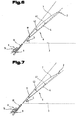
- the presentation of the Fig. 6 shows the sighting of the target 2 with the target device 8 at - after the shooting of the weapon 9 unchanged - relative position of the line of sight 4 through the Visual beam path of the target device 8 relative to the barrel axis 10 of the firearm 9.
- a change in Trajekotrie 7 of the projectile towards a relative to the line of sight 4 slightly flatter trajectory and the target 2 would be missed above.
- no shot is fired at the target 2 in this situation, but instead by the shooter 1, the device 21 (FIG. Fig. 4 ) while keeping the reticle 12 aligned with the target 2.
- microprocessor 22 of device 21 determines the equivalent horizontal distance E, which is finally displayed on display 26.
- Sagittarius 1 will now select the target corresponding to the displayed equivalent horizontal distance E. This is equivalent to the selection of a different from the line of sight 4, new sighting line 41, which includes a relative to the attachment angle 11 smaller angle 42 with the barrel axis 10 of the weapon 9.
- the shooter 1 now has the ability to align the sighting line 42 on the target 2 out.
- the weapon 9 is pivoted so far by the shooter 1 that the sighting line 41 forms the new line of sight on the target 2, whereby the trajectory of the projectile according to the trajectory 7 changes to the target 2 out.
- the barrel axis 10 of the weapon 9 is thus in Fig. 7 opposite the position in Fig. 6 pivoted at an angle corresponding to the difference between the attachment angle 11 and the new attachment angle 42.
- the relative position between the line of sight 4 of the target device 8 and the barrel axis 10 of the weapon 9 is thereby achieved a direct change of the attachment angle 11 by means of the height tower 16. That is, for the sighting of the target 2 in both situations, the same reticle 12 (FIG. Fig. 4 ) is aligned with the objective 2.
- the weapon 9 is rotated by an angle corresponding to the value of the difference between the original attachment angle 11 and the new modified attachment angle 42 by the shooter 1 pivoted to hit the target 2 safely when making a shot.
- the described adjustment to the height tower 16 for changing the relative position between the line of sight 4 passing through the visual beam path of the aiming device 8 and the running axis 10 of the weapon 9 can be done manually by the shooter 1, but advantageously automatically, for example by an electromotive adjustment , executed.
- the required correction when sighting a target 2 when executing an angle shot is thus feasible by a method for determining a replacement distance between a location of a shooter 1 and a point of impact of a projectile in the horizontal plane 3.
- the replacement distance is taken into account instead of the target distance D 6 when sighted by the shooter 1.
- the target distance D 6 between the location and the target 2, which are arranged on the line of sight 4, and the elevation angle ⁇ 5, which is enclosed by the line of sight 4 with the horizontal plane 3, are then determined. Then, based on exclusively on non-ballistic characteristics, such as the determined target distance D 6 and the elevation angle ⁇ 5, a correction function is determined. By applying the correction function to the measured value of the target distance D 6, the value of a replacement distance in a horizontal plane 3 is then determined. This value of the equivalent distance is then used to change the relative position between the line of sight 4 and the barrel axis 10 of the weapon 9 by the difference of the previously determined target distance and the determined replacement distance.
- the correction function is preferably realized by correction factors KF from a correction factor table, in which a value of the correction factor KF is assigned to a value pair of a value of the target distance D 6 and a value of the weft angle ⁇ 5.
Landscapes
- Engineering & Computer Science (AREA)
- General Engineering & Computer Science (AREA)
- Physics & Mathematics (AREA)
- Optics & Photonics (AREA)
- Aiming, Guidance, Guns With A Light Source, Armor, Camouflage, And Targets (AREA)
Abstract
Description
Die Erfindung betrifft ein Verfahren und eine Vorrichtung zur Bestimmung einer anstelle der Zieldistanz zu berücksichtigenden Ersatzdistanz zum Anvisieren eines Ziels mit einer Zieleinrichtung einer Schusswaffe entsprechend den Oberbegriffen der Ansprüche 1, 2, 3, 17, 23 und 27.The invention relates to a method and a device for determining a replacement distance to be considered instead of the target distance for sighting a target with a target device of a firearm according to the preambles of
Zieleinrichtungen, insbesondere Zielfernrohre, werden üblicherweise auf der Waffe montiert und in Verbindung mit dieser eingeschossen. Unter Waffen sind solche Waffen zu verstehen, welche ein Projektil unter einer gestreckten bzw. leicht gekrümmten Flugbahn direkt auf ein Ziel abfeuern. Dieses Einschießen erfolgt bei einer festen Schussentfernung von beispielsweise 100 m mit einer horizontal ausgerichteten Visierlinie auf ein Ziel und unter Verwendung einer für die Waffe typischen Munition (Laborierung). Zur Kompensation des Geschoßabfalls auf ihrer Flugbahn zwischen der Schusswaffe und dem Ziel ist die Laufachse der Schusswaffe um einen Aufsatzwinkel relativ zu der Visierlinie der Zielfeinrichtung geneigt. Beim Einschießen der Schusswaffe wird dieser Aufsatzwinkel so eingestellt, dass der tatsächliche Auftreffpunkt des Geschoßes mit dem gewünschten Auftreffpunkt, das heißt dem anvisierten Ziel zusammenfällt. Bei einem realen Schuss in der praktischen Anwendung müssen Abweichungen zu diesen Einschießbedingungen berücksichtigt werden. Einflussfaktoren, die eine Veränderung der Ballistik bewirken, sind beispielsweise Luftdruck und Lufttemperatur, die Anfangsgeschwindigkeit und der Widerstandsbeiwert bzw. ballistische Koeffizient des Geschoßes, seitliches Verkanten der Schusswaffe oder ein Winkelschuss nach oben oder nach unten.Targeting devices, in particular riflescopes, are usually mounted on the weapon and shot in conjunction with this. Weapons are to be understood as weapons which fire a projectile under an extended or slightly curved trajectory directly onto a target. This shooting takes place at a fixed firing range of, for example, 100 m with a horizontally aligned line of sight on a target and using a typical for the weapon ammunition (laboratory). To compensate for the projectile drop in its trajectory between the firearm and the target, the barrel axis of the firearm is tilted about an attachment angle relative to the sight line of the target barrel. When firing the firearm, this attachment angle is adjusted so that the actual point of impact of the projectile coincides with the desired impact point, that is to the intended target. In the case of a real shot in practical application, deviations from these shooting conditions must be taken into account. Influencing factors that cause a change in the ballistics, for example, air pressure and temperature, the initial speed and the coefficient of resistance or ballistic coefficient of the projectile, lateral tilting of the firearm or an angle shot up or down.
Die Abweichung bei einem Winkelschuss entsteht durch die veränderte Richtung der Geschoßbewegung relativ zur Richtung der auf das Geschoß wirkenden Schwerkraft. Ein Vergleich der Geschoßflugbahn beim Winkelschuss mit der Geschoßflugbahn bei einem horizontalen Schuss zeigt, dass die Geschoßflugbahn bei einem Winkelschuss relativ zur Visierlinie etwas flacher verläuft. Bliebe die Visierlinie bzw. der Haltepunkt auf das Ziel wie bei einem horizontalen Schuss gerichtet, würde es zu einem sogenannten Hochschuss kommen. Ein solcher kann verhindert werden, indem der Abgangswinkel (Erhöhung), das heißt der Winkel zwischen der Laufachse und einer horizontalen Ebene verringert wird. Dies kann entweder durch Verringerung des Aufsatzwinkels (Visierwinkel) oder des Höhenwinkels (Geländewinkel) erfolgen. Diese Korrektur des Werts des Abgangswinkels, mit dem die Zieleinrichtung relativ zum Ziel bzw. die Korrektur, mit dem die Visierlinie auf das Ziel ausgerichtet wird, ist gleichbedeutend mit der Berücksichtigung einer Ersatzdistanz, die anstelle der tatsächlichen Zieldistanz für das Anvisieren des Ziels verwendet wird. Dies kann auch ausgedrückt werden durch den Begriff der äquivalenten horizontalen Entfernung E. Diese ist beispielsweise bei Verwendung eines sogenannten ballistischen Absehens (Fadenkreuz) von Bedeutung, wobei in dem Absehen unterschiedliche vertikale Markierungen vorgesehen sind, die unterschiedlichen Fleckschussentfernungen entsprechen. Wird nun bei einem Winkelschuss die Zieleinrichtung so eingestellt, als ob sich das Ziel nicht in der tatsächlichen Entfernung D sondern in einer gemeinsamen Horizontalebene mit der Schusswaffe unter einer Zieldistanz mit einem Wert entsprechend der äquivalenten horizontalen Entfernung befinden würde, so ist nun auch ein Fleckschuss gewährleistet. Eine andere Möglichkeit der Berücksichtigung der erforderlichen Korrektur der Ausrichtung der Schusswaffe bzw. der Zieleinrichtung zum Anvisieren des Ziels besteht darin, über den Höhenturm der Zieleinrichtung das Absehen (Fadenkreuz) der Höhe nach entsprechend der äquivalenten horizontalen Entfernung zu justieren. Andererseits sind auch moderne Zieleinrichtungen bekannt, die integrierte ballistische Rechner aufweisen und notwendige Korrekturen entweder numerisch oder in Form von variablen Haltepunkten anzeigen.The deviation in an angular shot is due to the changed direction of the projectile movement relative to the direction of the force acting on the projectile gravity. A comparison of the projectile trajectory at the angle shot with the projectile trajectory in a horizontal shot shows that the projectile trajectory is somewhat flatter with an angle shot relative to the sight line. If the line of sight or the breakpoint were to be aimed at the target as in a horizontal shot, a so-called high shot would occur. Such can be prevented by reducing the departure angle (increase), that is, the angle between the travel axis and a horizontal plane. This can be done either by reducing the attachment angle (sighting angle) or the elevation angle (terrain angle) respectively. This correction of the value of the departure angle at which the destination device relative to the destination or the correction with which the sighting line is aligned with the destination is equivalent to the consideration of a substitute distance which is used instead of the actual target distance for the sighting of the destination. This can also be expressed by the concept of equivalent horizontal distance E. This is important, for example, when using a so-called ballistic reticle (reticule), wherein in the reticle different vertical markings are provided, which correspond to different spot-shot distances. If now the aiming device is set at an angle shot, as if the target would not be in the actual distance D but in a common horizontal plane with the firearm below a target distance with a value corresponding to the equivalent horizontal distance, now also a spot shot is guaranteed , Another way of taking into account the necessary correction of the orientation of the firearm or sighting device for sighting the target is to adjust the reticle (height) of the height according to the equivalent horizontal distance over the height tower of the target device. On the other hand, modern aiming devices are known which have integrated ballistic calculators and display necessary corrections either numerically or in the form of variable breakpoints.
Allen diesen Möglichkeiten gemeinsam ist das Erfordernis durch irgendein Verfahren in möglichst zuverlässiger Weise das Ausmaß der erforderlichen Korrektur bei einem Winkelschuss zu bestimmen bzw. zu berechnen. Es ist somit die Aufgabe der vorliegenden Erfindung ein Verfahren bzw. eine Vorrichtung anzugeben, mit dem/der bei Ausführung eines Winkelschusses mit einer Schusswaffe auf vereinfachte Weise eine hohe Treffsicherheit erreicht werden kann.Common to all these possibilities is the need, by any method, to determine, as accurately as possible, the degree of correction required in an angle shot. It is therefore an object of the present invention to provide a method and a device, with the / in the execution of an angle shot with a firearm in a simplified manner, a high accuracy can be achieved.
Zum besseren Verständnis der Erfindung wird diese anhand der nachfolgenden Figuren näher erläutert.For a better understanding of the invention, this will be explained in more detail with reference to the following figures.
Es zeigen jeweils in stark schematisch vereinfachter Darstellung:
- Fig. 1
- eine relative räumliche Anordnung bei einem Winkelschuss eines Schützten auf ein in erhöhter Lage angeordnetes Ziel;
- Fig. 2
- eine Gegenüberstellung der Trajektorien eines Geschoßes beim Anvisieren des Ziels bei einem Winkelschuss und bei einem horizontaler Schuss;
- Fig. 3
- ein Bild beim Blick durch eine Zieleinrichtung beim Anvisieren des Ziels gemäß
Fig. 2 ; - Fig. 4
- eine Vorrichtung zur Bestimmung der äquivalenten horizontalen Entfernung E mit dem Blick durch eine Zieleinrichtung gemäß
Fig. 3 ; - Fig. 5
- ein Flussdiagramm der Verfahrensschritte des Verfahrens zur Bestimmung der äquivalenten horizontalen Entfernung E;
- Fig. 6
- das Anvisieren eines Ziels mit der Zieleinrichtung einer Schusswaffe;
- Fig. 7
- das Anvisieren des Ziels gemäß
Fig. 6 unter Berücksichtigung der erfindungsgemäßen Korrektur.
- Fig. 1
- a relative spatial arrangement in the case of an angle shot of a shoot on an elevated target;
- Fig. 2
- a comparison of the trajectories of a projectile when aiming the target in an angle shot and a horizontal shot;
- Fig. 3
- an image when looking through a target device when aiming the target according to
Fig. 2 ; - Fig. 4
- a device for determining the equivalent horizontal distance E with the view through a target device according to
Fig. 3 ; - Fig. 5
- a flowchart of the method steps of the method for determining the equivalent horizontal distance E;
- Fig. 6
- sighting a target with the aiming device of a firearm;
- Fig. 7
- targeting the target according to
Fig. 6 taking into account the correction according to the invention.
Einführend sei festgehalten, dass in den unterschiedlich beschriebenen Ausführungsformen gleiche Teile mit gleichen Bezugszeichen bzw. gleichen Bauteilbezeichnungen versehen werden, wobei die in der gesamten Beschreibung enthaltenen Offenbarungen sinngemäß auf gleiche Teile mit gleichen Bezugszeichen bzw. gleichen Bauteilbezeichnungen übertragen werden können. Auch sind die in der Beschreibung gewählten Lageangaben, wie z.B. oben, unten, seitlich usw. auf die unmittelbar beschriebene sowie dargestellte Figur bezogen und sind bei einer Lageänderung sinngemäß auf die neue Lage zu übertragen. Weiters können auch Einzelmerkmale oder Merkmalskombinationen aus den gezeigten und beschriebenen unterschiedlichen Ausführungsbeispielen für sich eigenständige, erfinderische oder erfmdungsgemäße Lösungen darstellen.By way of introduction, it should be noted that in the differently described embodiments, the same parts are provided with the same reference numerals or the same component names, wherein the disclosures contained in the entire description can be mutatis mutandis to the same parts with the same reference numerals or component names. Also, the location information chosen in the description, such as top, bottom, side, etc. related to the immediately described and illustrated figure and are to be transferred to the new situation mutatis mutandis when a change in position. Furthermore, individual features or combinations of features from the various exemplary embodiments shown and described can also represent separate, inventive or erfmdungsgemäße solutions.
Sämtliche Angaben zu Wertebereichen in gegenständlicher Beschreibung sind so zu verstehen, dass diese beliebige und alle Teilbereiche daraus mit umfassen, z.B. ist die Angabe 1 bis 10 so zu verstehen, dass sämtliche Teilbereiche, ausgehend von der unteren Grenze 1 und der oberen Grenze 10 mitumfasst sind, d.h. sämtliche Teilbereich beginnen mit einer unteren Grenze von 1 oder größer und enden bei einer oberen Grenze von 10 oder weniger, z.B. 1 bis 1,7, oder 3,2 bis 8,1 oder 5,5 bis 10.All statements on ranges of values in objective description are to be understood as including any and all sub-ranges thereof, eg the
Die
Die
Eine Laufachse 10 der Schusswaffe 9 ist relativ zu der Visierlinie bzw. Sichtlinie 4 der Zieleinrichtung 8 um einen Aufsatzwinkel 11 verschwenkt angeordnet. Dieser Aufsatzwinkel 11 ist beim Einschießen der Schusswaffe 9 derart justiert, dass die Trajektorie 7' des Geschoßes die Horizontalebene 3 in der Einschießdistanz schneidet. Damit wird gerade die Einschießbedingung erfüllt, dass der tatsächliche Auftreffpunkt des Geschoßes mit dem gewünschten Auftreffpunkt des in der Einschießdistanz angeordneten Ziels 2' zusammenfällt.A running
Das Einschießen der Schusswaffe 9 erfolgt in üblicher Weise dadurch, dass eine Folge von Schüssen auf ein sich in der Einschießdistanz befindliches Ziel Z ausgeführt wird. Das heißt die Entfernung zwischen dem Standort des Schützen 1 bzw. der Mündung der Schusswaffe 9 und dem Ziel Z wird gleich der Einschießdistanz gewählt, wobei sich außerdem die Mündung der Schusswaffe 9 und das Ziel Z in der gemeinsamen Horizontalebene 3 befinden. Wird nun nach einem Schuss auf das Ziel Z eine Abweichung des Auftreffpunkts des Geschoßes von dem Ziel Z festgestellt, so wird eine Veränderung der Relativstellung zwischen der Sichtlinie 4 und der Laufachse 10 der Schusswaffe 9 vorgenommen, mit der erreicht werden soll, dass der Auftreffpunkt des Geschoßes bei Ausführung eines weiteren Schusses näher an dem Ziel Z zu liegen kommt. Eine solche Veränderung der Relativstellung der Sichtlinie 4 relativ zu der Laufachse 10 der Waffe 9 wird üblicherweise dadurch vorgenommen, dass an einem Höhenturm 16 der Zieleinrichtung 8 bzw. eines Zielfernrohrs eine Verstellung vorgenommen wird, durch die der Verlauf der Sichtlinie 4 durch den visuellen Strahlengang der Zieleinrichtung 8 hindurch verändert wird. Durch eine solche Veränderung können sowohl Abweichungen des Auftreffpunktes des Geschoßes von dem Ziel Z in horizontaler als auch in vertikaler Richtung kompensiert werden. Zur Verringerung einer Abweichung in vertikaler Richtung wird bei einer solchen Einstellung an dem Höhenturm 16 der Aufsatzwinkel 11 verändert. Zum Einschießen der Schusswaffe 9 wird die Folge von Probeschüssen und Neueinstellungen der Relativstellung der Sichtlinie 4 relativ zu der Laufachse 10 der Waffe 9 so lange fortgesetzt bis eine ausreichend hohe Treffsicherheit erreicht wird.The firing of the
Gemäß einer verallgemeinerten Vorgehensweise erfolgt das Einschießen der Schusswaffe 9 unter einem gegenüber der Horizontalebene 3 geneigten Einschießwinkel mit einem vordefinierten Wert. Dies kann für eine Schusswaffe 9 günstig sein, die beispielsweise regelmäßig von einem Hochsitz über einem sonst ebenen, horizontalen Gelände abgefeuert wird. Für eine solche Anwendung kann das Einschießen der Schusswaffe 9 unter einem vorgewählten Einschießwinkel mit einem negativen Wert erfolgen. Dies erfolgt wiederum dadurch, dass mit der Schusswaffe 9 eine Folge von Probeschüssen und Neueinstellungen der Relativstellung der Sichtlinie 4 relativ zu der Laufachse 10 der Waffe 9 solange fortgesetzt wird, bis eine ausreichend hohe Treffsicherheit erreicht ist.In accordance with a generalized procedure, the firing of the
Wird nun die Schusswaffe 9 auf das über der Horizontalebene 3 erhöht angeordnete Ziel 2 gerichtet und dazu die Visierlinie bzw. Sichtlinie 4 der Zieleinrichtung 8 auf das Ziel 2 ausgerichtet, so muss eine Veränderung der Flugbahn eines mit der Schusswaffe 9 abgeschossenen Geschoßes berücksichtigt werden, wobei die Trajektorie 7 des Geschoßes nun relativ zur Visierlinie etwas flacher verläuft, das heißt eine geringere Krümmung aufweist als im Fall des Horizontalschuss mit der Trajektorie 7'. Das Ziel 2 wird durch die Trajektorie 7 somit oberhalb verfehlt. Dieser Fehler kann dadurch korrigiert werden, dass die Schusswaffe 9 etwas zur Horizontalebene 3 hin verschwenkt wird, sodass die ursprüngliche Visierlinie bzw. Sichtlinie 4 auf einen unterhalb des Ziels 2 liegenden Punkt ausgerichtet ist und die Sichtlinie 4 einen Winkel mit der Horizontalebene 3 einschließt dessen Wert kleiner ist als der Wert des Höhenwinkels α 5. Eine solche Korrektur wird anhand der nachfolgend beschriebenen
Im Falle der Verwendung einer auf einen - gegenüber der Horizontalebene 3 geneigten - Einschießwinkel eingeschossenen Schusswaffe 9 ist für diese Korrektur bzw. Korrekturfunktion anstelle des Höhenwinkels α 5 die Winkeldifferenz zwischen dem Höhenwinkel α 5 und dem Einschießwinkel zu berücksichtigen.In the case of the use of a firing
Die
Bei diesem Ausführungsbeispiel weist die Zieleinrichtung 8 eine Zielmarkenanordnung mit einem Fadenkreuz 12 und zusätzlichen Zielmarken 13, 14 und 15 auf. Die Anordnung des Bilds des Ziels 2 relativ zu dem Fadenkreuz 12 bzw. den Zielmarken 13, 14, 15 entspricht jener Situation in der die vorstehend erläuterte Korrektur bereits berücksichtigt ist. Die Sichtlinie 4 der Zieleinrichtung 8 - sie entspricht dem Kreuzungspunkt des Fadenkreuzes 12 - ist auf einen Punkt unterhalb des Ziels 2 ausgerichtet. Demgemäß erscheint das Bild des Ziels 2 oberhalb des Fadenkreuzes 12 - in diesem Fall zur Deckung gebracht mit der Zielmarke 13.In this embodiment, the
Das Bild gemäß
Die den Zielmarken 13, 14, 15 und dem Fadenkreuz 12 zugeordneten Werte der Zieldistanz D 6 für Horizontalschüsse sind nun aber auch bei Winkelschüssen unter einem Höhenwinkel α 5 von Bedeutung, in dem sie als sogenannte äquivalente horizontale Entfernung E zur Berücksichtigung der vorbeschriebenen Korrektur der Ausrichtung der Schusswaffe 9 bzw. der Sichtlinie 4 der Zieleinrichtung 8 auf das Ziel 2 verwendet werden. Auf diese Weise wird von dem Schützen 1 anstelle des Werts der tatsächlichen Zieldistanz D 6 eine Ersatzdistanz für das Anvisieren verwendet.The values of the
Von entscheidender Bedeutung ist nun, die erforderliche Korrektur quantitativ bestimmen zu können. Dazu ist seit langem eine als "Rifleman's Rule" bezeichnete Faustregel bekannt, nach der die Zieldistanz D 6 mit dem Kosinus des Höhenwinkels α 5 zu multiplizieren ist, um den Wert der äquivalenten horizontalen Entfernung E zu erhalten. ![]()
![]()
Wird nun bei einem Winkelschuss unter einem Höhenwinkel α 5 die Zieleinrichtung 8 so eingestellt, als ob sich das Ziel 2 in derselben Horizontalebene 3 wie die Schusswaffe 9 und in der äquivalenten horizontalen Entfernung E befinden würde, so ist nun das Treffen des Ziels 2 (ein Fleckschuss) gewährleistet.If the
Die Berechnung der äquivalenten horizontalen Entfernung E nach der Rifleman's Rule entsprechend vorstehend angegebener Gleichung 1 ist jedoch nur eine Näherung, die nur bei relativ kurzen Zieldistanzen D 6 und kleinen Werten des Höhenwinkels α 5 ausreichend genaue Ergebnisse liefert.However, the calculation of the equivalent horizontal distance E according to the Rifleman's Rule according to
Die Berechnung der äquivalenten horizontalen Entfernung E nach Gleichung 1 kann auch interpretiert werden als eine Modifikation der Zieldistanz D 6 mit einem Korrekturfaktor KF, der im Falle der Rifleman's Rule nur vom Höhenwinkel α 5 abhängt. ![]()
![]()
![]()
![]()
Im Stand der Technik sind bereits ballistische Programme (z.B. QuickTARGET, EXBAL, Sierra Infinity) als auch Zieleinrichtungen oder Entfernungsmesser mit integriertem ballistischem Rechner bekannt, bei denen zur Bestimmung einer Korrektur bzw. des Korrekturfaktors KF Umwelteinflüsse wie die Temperatur, die Luftfeuchte, die Windstärke, der Luftdruck, aber auch insbesondere Daten der Laborierung bzw. der verwendeten Munition berücksichtig werden. Derartige Geräte erlauben die Berücksichtigung der Korrektur entweder durch numerische Angabe der äquivalenten horizontalen Entfernung E oder die Anzeige eines variablen Haltepunktes (das heißt variabler Zielmarken 13, 14, 15). Somit wird ein Korrekturfaktor KF verwendet, der von mehreren Parametern abhängig ist. ![]()
![]()
Eine Möglichkeit zur Durchführung des erfindungsgemäßen Verfahrens zur Bestimmung einer äquivalenten horizontalen Entfernung E zum Anvisieren eines Ziels 2 mit einer Zieleinrichtung 8 einer Schusswaffe 9 wird anhand von
Die Vorrichtung 21 zur Bestimmung der äquivalenten horizontalen Entfernung E kann sowohl als ein von der Schusswaffe 9 bzw. der Zieleinrichtung unabhängiges Gerät ausgeführt sein, kann aber alternativ auch einen Bestandteil der Schusswaffe 9 oder der Zieleinrichtung 8 bilden. Im zuletzt genannten Fall ist die Anzeige 26 der Vorrichtung 21 vorzugsweise in den Strahlengang der Zieleinrichtung 8 integriert. Die Anzeige 26 ist dazu in einer der Bildebenen der Optik der Zieleinrichtung 8 eingeblendet, sodass der Wert der berechneten äquivalenten horizontalen Entfernung E dem Schützen 1 in dem gleichen durch die Zieleinrichtung 8 dargestellten Gesichtsfeld erscheint.The
Gemäß einer alternativen Ausbildung einer Kombination der Vorrichtung 21 mit einer Zieleinrichtung 8 erfolgt anstatt einer numerischen Anzeige der äquivalenten horizontalen Entfernung E auf der Anzeige 26 durch den Mikroprozessor 22 die Berechnung eines variablen Haltepunktes und dessen automatisiertes Einblenden in den Strahlengang der Zieleinrichtung 8, das heißt der Anzeige einer entsprechend positionierten Zielmarke 13, 14, 15. Es ist aber auch denkbar, mittels einer automatischen (motorisierten) mechanischen Verstellung des Höhenturms oder einer Verstellung der Visierlinie durch Verschieben eines optischen Elementes im Strahlengang der Zieleinrichtung die notwendige Korrektor zu berücksichtigen.According to an alternative embodiment of a combination of the
Von Vorteil ist weiters eine Ausführung der Zieleinrichtung 8, bei der der Entfernungsmesser 23 in den optischen Strahlengang der Zieleinrichtung 8 zumindest teilweise integriert ist. Dies kann beispielsweise dadurch realisiert sein, dass - z.B. bei Ausführung des Entfernungsmessers 23 durch einen Laserentfernungsmesser - der zu dem Ziel 2 ausgesendete Laserstrahl und/oder das von dem Ziel 2 reflektierte Laserlicht durch das Objektiv der Zieleinrichtung 8 hindurch verläuft.Another advantage is an embodiment of the
Gemäß dem erfindungsgemäßen Verfahren zur Bestimmung der äquivalenten horizontalen Entfernung E erfolgt deren Berechnung auf der Basis einer Korrektur, welche auf einem Wertepaar eines Werts der Zieldistanz D 6 und eines Werts des Höhenwinkels α 5 basiert. Es hat sich nämlich überraschenderweise gezeigt, dass mit einer Korrektur, die alleine für unterschiedliche Werte von Zieldistanzen D 6 und unterschiedliche Werte von Höhenwinkeln α 5 bestimmt wird, die Vorteile der oben beschriebenen Methoden (nämlich einfach und genau) verknüpft werden können, ohne deren Nachteile (nämlich Notwendigkeit der Kenntnis über die ballistischen Laborierungsdaten und Einschränkung auf kurze Distanzen und kleine Höhenwinkel) in Kauf nehmen zu müssen. Eine ausreichend genaue Berechnung der äquivalenten horizontalen Entfernung E zum Anvisieren des Ziels 2 ist somit möglich. Das erfindungsgemäße Verfahren zur Bestimmung der äquivalenten horizontalen Entfernung E basiert daher auf Korrekturfaktoren KF für die gilt: ![]()
![]()
Gemäß einem ersten Ausführungsbeispiel wird folgende Korrekturfaktor-Tabelle verwendet.
Die Zuordnung von Korrekturfaktoren KFij zu Wertpaaren (Di, αj) kann beispielsweise nach Durchführung entsprechender Probeschüsse erfolgen.The assignment of correction factors KF ij to pairs of values (D i , α j ) can take place, for example, after carrying out appropriate test shots.
Gemäß einer weiteren Ausführungsvariante des erfindungsgemäßen Verfahrens ist vorgesehen, zur Bestimmung der Korrekturfaktor-Tabelle handelsübliche ballistische Programme zu verwenden. Mittels handelsüblicher Ballistiksoftware ist es möglich, für auswählbare bzw. einstellbare Munitionen bzw. Laborierungen sowohl für den horizontalen als auch für den Winkelschuss Parameter der entsprechenden Trajektorien 7 und somit Bedingungen für einen Fleckschuss, wie den Aufsatzwinkel oder die notwendige Verstellung des Höhenturms der Zieleinrichtung 8 zu berechnen. Ein Ergebnis einer solchen Berechnung ist auch die Bestimmung der äquivalenten horizontalen Entfernung E. Beispiele für solche handelsübliche ballistische Programme sind QuickTARGET von H. Brömel - DE, EXBAL von Perry Systems - USA oder Sierra Bullets Infinity Exterior Ballistics Software von Sierra - USA.According to a further embodiment variant of the method according to the invention, it is provided to use commercially available ballistic programs for determining the correction factor table. By means of commercially available ballistic software, it is possible for selectable or adjustable ammunitions or for both horizontal and angular angle parameters of the
Die Auswertung von ballistischen Berechnungen mit handelsüblichen ballistischen Programmen erlaubt auch die Ermittlung von Korrekturfaktoren für unterschiedliche Laborierungen bzw. Munitionen (siehe Gleichung 4). Gemäß diesem Ausführungsbeispiel der Erfindung ist nun vorgesehen, dass zur Bestimmung der Werte der Korrekturfaktoren KF(Di, αj) der Korrekturfaktor-Tabelle mit einem Ballistikprogramm Werte des Korrekturfaktors KF aus Daten der Laborierung einer Munition berechnet werden und ein Mittelwert aus Werten von Korrekturfaktoren KF zu jeweils unterschiedlichen Laborierungen gebildet wird. Die Elemente KFij der Korrekturfaktor-Tabelle bilden somit eine zweidimensionale Matrix, wobei sich diese Korrekturfaktoren KFij = KF(Di, αj) berechnen zu: 
In dem nun beschriebenen Beispiel zur Bestimmung einer Korrekturfaktor-Tabelle wurde die Ballistiksoftware QuickTARGET verwendet und wurden die Trajektorien 7 für drei unterschiedliche Munitionen bzw. Laborierungen jeweils unter Höhenwinkeln α 5 mit Werten von 15° und 35° und damit Korrekturfaktoren KFij zur Bestimmung der äquivalenten horizontalen Entfernung E berechnet. Die Berechnungen erfolgten jeweils unter Zugrundelegung der drei Munitionen bzw. Laborierungen wie in der nachfolgenden Tabelle angegeben. Dabei ist in der Spalte BC der ballistische Koeffizient und in der Spalte v0 die Mündungsgeschwindigkeit (Austrittsgeschwindigkeit) des Geschoßes in m/s (Meter / Sekunde) angegeben.
Nach Bestimmung der Werte der Korrekturfaktoren KF (Di, αj, Laborierungl) wurden nach Anwendung der Gleichung 6, das heißt durch Mittelwertbildung, die Elemente KFij der Korrekturfaktor-Tabelle bestimmt, wie in der nachfolgenden Tabelle angegeben.
Für die Anwendung des erfindungsgemäßen Verfahrens ist es ausreichend, die so erhaltene Korrekturfaktor-Tabelle in dem Speicher 25 der Vorrichtung 21 (
Bei den in diesem Ausführungsbeispiel verwendeten Munitionen bzw. Laborierungen handelt es sich ganz allgemein um solche mit einer sehr flachen Flugbahn bzw. Trajektorie 7' des Geschoßes, wie sie für direkte Schüsse bzw. direktes Feuer zum Einsatz kommen. Charakteristisch für diese Munitionen ist eine hohe Rasanzzahl. Das heißt bei der Ausführung eines waagrechten Schusses ergeben sich hohe Werte des Quotienten aus der Zieldistanz D 6 und der Distanz zwischen dem Bahngipfel der Trajektorie 7' und der Sichtlinie 4' (
Gemäß einer weiteren Ausführungsvariante des erfindungsgemäßen Verfahrens ist vorgesehen, im Unterschied zur Mittelwertbildung gemäß Gleichung 6 eine gewichtete Mittelwertbildung anzuwenden. Dazu werden bevorzugt Beiträge von Laborierungen mit einer flacheren Trajektorie 7 für größere Schussweiten, bzw. Beiträge von Laborierungen mit einer hohen Ransanzzahl höher gewichtet und Beiträge von Laborierungen mit einer stärker gekrümmten Trajektorie 7, bzw. mit einer kleineren Ransanzzahl geringer gewichtet.According to a further embodiment variant of the method according to the invention, it is provided to apply a weighted mean value formation in contrast to the averaging according to
Anhand der Darstellungen in den
Die Darstellung der
Der Schütze 1 hat nun die Möglichkeit die Visierlinie 42 auf das Ziel 2 hin auszurichten. Dazu wird die Waffe 9 von dem Schützen 1 soweit verschwenkt, dass die Visierlinie 41 die neue Sichtlinie auf das Ziel 2 bildet, wodurch sich auch die Flugbahn des Geschoßes gemäß der Trajektorie 7 auf das Ziel 2 hin verändert. Die Laufachse 10 der Waffe 9 ist somit in
Gemäß einer alternativen Ausführungsvariante erfolgt das Korrigieren der Ausrichtung der Schusswaffe 9 auf das Ziel 2 hin durch eine Anpassung mit Hilfe einer Verstellung des Höhenturms 16 der Zieleinrichtung 8. Die Relativstellung zwischen der Sichtlinie 4 der Zieleinrichtung 8 und der Laufachse 10 der Waffe 9 wird dabei durch eine direkte Veränderung des Aufsatzwinkels 11 mit Hilfe des Höhenturms 16 erreicht. Das heißt, dass für das Anvisieren des Ziels 2 in beiden Situationen das gleiche Fadenkreuz 12 (
Die erforderliche Korrektur beim Anvisieren eines Zieles 2 bei Ausführung eines Winkelschusses ist somit durch ein Verfahren zum Ermitteln einer Ersatzdistanz zwischen einem Standort eines Schützen 1 und einem Auftreffpunkt eines Geschoßes in der Horizontalebene 3 durchführbar. Die Ersatzdistanz wird dabei anstelle der Zieldistanz D 6 beim Anvisieren durch den Schützen 1 berücksichtigt. Dies setzt zunächst ein Einschießen der Waffe 9 voraus, wobei die Relativstellung der Sichtlinie 4 durch den visuellen Strahlengang der Zieleinrichtung 8 bzw. des Zielfernrohrs relativ zu der Laufachse 10 der Waffe 9 so eingestellt wird, dass für ein vorbestimmbares Geschoß und eine vorbestimmbare Einschießdistanz für Horizontalschüsse eine gewünschte hohe Treffsicherheit erreicht wird. Bei der Durchführung eines Winkelschusses wird sodann die Zieldistanz D 6 zwischen dem Standort und dem Ziel 2, die auf der Sichtlinie 4 angeordnet sind, als auch der Höhenwinkel α 5, der von der Sichtlinie 4 mit der Horizontalebene 3 eingeschlossen wird, ermittelt. Daraufhin wird, basierend ausschließlich auf nicht ballistischen Kennwerten, wie der ermittelten Zieldistanz D 6 und dem Höhenwinkel α 5, eine Korrekturfunktion bestimmt. Durch Anwendung der Korrekturfunktion auf den gemessenen Wert der Zieldistanz D 6 wird sodann der Wert einer Ersatzdistanz in einer Horizontalebene 3 bestimmt. Dieser Wert der Ersatzdistanz wird sodann dazu herangezogen, die Relativstellung zwischen der Sichtlinie 4 und der Laufachse 10 der Waffe 9 um die Differenz der vorher ermittelten Zieldistanz und auf die ermittelte Ersatzdistanz zu verändern. Die Korrekturfunktion wird vorzugsweise durch Korrekturfaktoren KF aus einer Korrekturfaktortabelle realisiert, in der jeweils einem Wertepaar eines Wert der Zieldistanz D 6 und eines Werts des Schusswinkels α 5 ein Wert des Korrekturfaktors KF zugeordnet ist.The required correction when sighting a
Die Ausführungsbeispiele zeigen mögliche Ausführungsvarianten des Verfahrens bzw. der Vorrichtung zur Bestimmung einer äquivalenten horizontalen Entfernung, wobei an dieser Stelle bemerkt sei, dass die Erfindung nicht auf die speziell dargestellten Ausführungsvarianten derselben eingeschränkt ist, sondern vielmehr auch diverse Kombinationen der einzelnen Ausführungsvarianten untereinander möglich sind und diese Variationsmöglichkeit aufgrund der Lehre zum technischen Handeln durch gegenständliche Erfindung im Können des auf diesem technischen Gebiet tätigen Fachmannes liegt. Es sind also auch sämtliche denkbaren Ausführungsvarianten, die durch Kombinationen einzelner Details der dargestellten und beschriebenen Ausführungsvariante möglich sind, vom Schutzumfang mit umfasst.The embodiments show possible embodiments of the method and the device for determining an equivalent horizontal distance, it being noted at this point that the invention is not limited to the specifically illustrated embodiments thereof, but rather also various combinations of the individual Embodiment variants are mutually possible and this possibility of variation due to the doctrine of technical action by objective invention in the skill of those working in this technical field expert. So are all conceivable embodiments, which are possible by combinations of individual details of the illustrated and described embodiment variant, includes the scope of protection.
Der Ordnung halber sei abschließend daraufhingewiesen, dass zum besseren Verständnis des Aufbaus der Vorrichtung zur Bestimmung einer äquivalenten horizontalen Entfernung diese bzw. deren Bestandteile teilweise unmaßstäblich und/oder vergrößert und/oder verkleinert dargestellt wurden.For the sake of organization, it should finally be pointed out that for a better understanding of the construction of the apparatus for determining an equivalent horizontal distance, these or their components have been shown partially unevenly and / or enlarged and / or reduced in size.
Die den eigenständigen erfinderischen Lösungen zugrundeliegende Aufgabe kann der Beschreibung entnommen werden.The task underlying the independent inventive solutions can be taken from the description.
Vor allem können die einzelnen in den
- 11
- SchützeSagittarius
- 22
- Zielaim
- 33
- HorizontalebeneWL
- 44
- Sichtlinieline of sight
- 55
- Höhenwinkel □Elevation angle □
- 66
- Zieldistanz DTarget distance D
- 77
- Trajektorietrajectory
- 88th
- Zieleinrichtungaimer
- 99
- Schusswaffefirearm
- 1010
- LaufachseWheel shaft
- 1111
- Aufsatzwinkeltop angle
- 1212
- Fadenkreuzcrosshairs
- 1313
- Zielmarketarget
- 1414
- Zielmarketarget
- 1515
- Zielmarketarget
- 1616
- Höhenturmtower height
- 1717
- 1818
- 1919
- 2020
- 2121
- Vorrichtungcontraption
- 2222
- Mikroprozessormicroprocessor
- 2323
- Entfernungsmesserrangefinder
- 2424
- Neigungssensortilt sensor
- 2525
- SpeicherStorage
- 2626
- Anzeigedisplay
- 2727
- 2828
- 2929
- 3030
- 3131
- Verfahrensschrittstep
- 3232
- Verfahrensschrittstep
- 3333
- Verfahrensschrittstep
- 3434
- Verfahrensschrittstep
- 3535
- Verfahrensschrittstep
- 3636
- Verfahrensschrittstep
- 3737
- 3838
- 3939
- 4040
- 4141
- Visierlinieline of sight
- 4242
- Winkelangle
Claims (16)
Priority Applications (1)
| Application Number | Priority Date | Filing Date | Title |
|---|---|---|---|
| EP18167201.5A EP3367047B1 (en) | 2011-04-06 | 2012-04-06 | Target device |
Applications Claiming Priority (1)
| Application Number | Priority Date | Filing Date | Title |
|---|---|---|---|
| ATA490/2011A AT511318B1 (en) | 2011-04-06 | 2011-04-06 | AIMING |
Related Child Applications (2)
| Application Number | Title | Priority Date | Filing Date |
|---|---|---|---|
| EP18167201.5A Division-Into EP3367047B1 (en) | 2011-04-06 | 2012-04-06 | Target device |
| EP18167201.5A Division EP3367047B1 (en) | 2011-04-06 | 2012-04-06 | Target device |
Publications (2)
| Publication Number | Publication Date |
|---|---|
| EP2508835A1 true EP2508835A1 (en) | 2012-10-10 |
| EP2508835B1 EP2508835B1 (en) | 2018-05-30 |
Family
ID=46000663
Family Applications (2)
| Application Number | Title | Priority Date | Filing Date |
|---|---|---|---|
| EP18167201.5A Active EP3367047B1 (en) | 2011-04-06 | 2012-04-06 | Target device |
| EP12002522.6A Active EP2508835B1 (en) | 2011-04-06 | 2012-04-06 | Target device |
Family Applications Before (1)
| Application Number | Title | Priority Date | Filing Date |
|---|---|---|---|
| EP18167201.5A Active EP3367047B1 (en) | 2011-04-06 | 2012-04-06 | Target device |
Country Status (3)
| Country | Link |
|---|---|
| US (1) | US8733647B2 (en) |
| EP (2) | EP3367047B1 (en) |
| AT (1) | AT511318B1 (en) |
Families Citing this family (5)
| Publication number | Priority date | Publication date | Assignee | Title |
|---|---|---|---|---|
| TWI464361B (en) | 2005-11-01 | 2014-12-11 | Leupold & Stevens Inc | Ballistic ranging methods and systems for inclined shooting |
| BE1024404B1 (en) * | 2016-07-15 | 2018-02-14 | Fn Herstal S.A. | SIGHT |
| AT519554B1 (en) | 2017-09-22 | 2018-08-15 | Swarovski Optik Kg | Method for determining a replacement distance between a location and a replacement impact point of a projectile |
| US10962331B2 (en) * | 2019-06-06 | 2021-03-30 | Bae Systems Information And Electronic Systems Integration Inc. | Dynamic weapon to target assignment using a control based methodology |
| CN115031580B (en) * | 2022-06-20 | 2023-10-24 | 无锡市星迪仪器有限公司 | High-precision gun correction method, processing device and high-precision gun correction system |
Citations (3)
| Publication number | Priority date | Publication date | Assignee | Title |
|---|---|---|---|---|
| US6873406B1 (en) * | 2002-01-11 | 2005-03-29 | Opti-Logic Corporation | Tilt-compensated laser rangefinder |
| US20070137088A1 (en) * | 2005-11-01 | 2007-06-21 | Leupold & Stevens, Inc. | Ballistic ranging methods and systems for inclined shooting |
| EP2148165A2 (en) * | 2008-07-24 | 2010-01-27 | Bushnell Inc. | Handheld rangefinder |
Family Cites Families (3)
| Publication number | Priority date | Publication date | Assignee | Title |
|---|---|---|---|---|
| DD277742A1 (en) * | 1988-12-06 | 1990-04-11 | Zeiss Jena Veb Carl | SCOPE |
| US7806331B2 (en) * | 2004-11-30 | 2010-10-05 | Windauer Bernard T | Optical sighting system |
| US7658031B2 (en) * | 2005-12-21 | 2010-02-09 | Bushnell, Inc. | Handheld rangefinder operable to determine hold over ballistic information |
-
2011
- 2011-04-06 AT ATA490/2011A patent/AT511318B1/en active
-
2012
- 2012-04-05 US US13/440,191 patent/US8733647B2/en active Active
- 2012-04-06 EP EP18167201.5A patent/EP3367047B1/en active Active
- 2012-04-06 EP EP12002522.6A patent/EP2508835B1/en active Active
Patent Citations (3)
| Publication number | Priority date | Publication date | Assignee | Title |
|---|---|---|---|---|
| US6873406B1 (en) * | 2002-01-11 | 2005-03-29 | Opti-Logic Corporation | Tilt-compensated laser rangefinder |
| US20070137088A1 (en) * | 2005-11-01 | 2007-06-21 | Leupold & Stevens, Inc. | Ballistic ranging methods and systems for inclined shooting |
| EP2148165A2 (en) * | 2008-07-24 | 2010-01-27 | Bushnell Inc. | Handheld rangefinder |
Also Published As
| Publication number | Publication date |
|---|---|
| EP2508835B1 (en) | 2018-05-30 |
| AT511318B1 (en) | 2014-12-15 |
| EP3367047A1 (en) | 2018-08-29 |
| AT511318A1 (en) | 2012-10-15 |
| US20120298749A1 (en) | 2012-11-29 |
| EP3367047B1 (en) | 2020-12-16 |
| US8733647B2 (en) | 2014-05-27 |
Similar Documents
| Publication | Publication Date | Title |
|---|---|---|
| EP1304539B1 (en) | Method and device for aiming a gun barrel and use of the device | |
| DE2736598A1 (en) | CROSSES FOR OPTICAL DEVICES | |
| EP2508835B1 (en) | Target device | |
| DE3145035A1 (en) | "SCOPE" | |
| DE102005007910A1 (en) | Firearm for long flight duration projectiles has fire guidance system with target data acquisition and adjusters for sight tube on weapon | |
| DE202005017276U1 (en) | Reticle for use in e.g. riflescope, has primary horizontal and vertical sight lines, and set of vertical secondary aiming marks, each indicating equal unit of measure and intersecting vertical central portion | |
| DE19719977C1 (en) | Video viewing-sight with integrated weapon control system for gun | |
| DE3209111A1 (en) | FIRE GUIDE SYSTEM FOR A BULLET | |
| AT518877B1 (en) | Adjustment element for adjusting a sighting line of an optical sighting device, as well as a telescopic sight with the adjusting element and weapon with the telescopic sight, and method for adjusting the sighting line | |
| DE3507007C2 (en) | ||
| DE3238848A1 (en) | METHOD AND DEVICE FOR ENTIRELY CORRECTING THE SHOOTING PROCESS FROM ONE SHOT TO THE FOLLOWING ON A GUN WITH THE STRAIGHT WAY | |
| DE102012213747A1 (en) | Method and target device for determining a probability of a hit of a target object | |
| DE2143871A1 (en) | FIRE CONTROL PROCEDURE AND DEVICE | |
| EP3460378B1 (en) | Device for determining a replacement distance between a location and an initial impact point of a projectile | |
| EP2047317B1 (en) | Telescopic sight | |
| DE102004034267A1 (en) | System for automatic elevation adjustment for weapon using a laser ranging optic connected to the weapon sight via a data link and computer | |
| EP2538166A1 (en) | Fire control device | |
| DE1951622B2 (en) | ARRANGEMENT FOR SIMULATED REPRESENTATION OF SHOOTING PATHS | |
| DE1946972B2 (en) | Weapon sighting and correcting device - includes indicator lamps in Wheatstone bridge for correction circuit | |
| DE102013111123A1 (en) | Method for adjusting a weft simulator to a predetermined target distance | |
| DE3236206C1 (en) | Procedure for determining the placement of the projectile impact on shooting simulators | |
| DE256155C (en) | ||
| DE472796C (en) | Procedure and device for determining the lateral direction in indirect shooting with cannons or machine guns | |
| DE3545831A1 (en) | Method for practising aiming using a laser firing simulator and a retroreflector at the target end, as well as a firing simulator for carrying out this method | |
| DE738327C (en) | Rifle scope tailored to the firearm to be used, the agreement of which contains two overlapping brands |
Legal Events
| Date | Code | Title | Description |
|---|---|---|---|
| PUAI | Public reference made under article 153(3) epc to a published international application that has entered the european phase |
Free format text: ORIGINAL CODE: 0009012 |
|
| AK | Designated contracting states |
Kind code of ref document: A1 Designated state(s): AL AT BE BG CH CY CZ DE DK EE ES FI FR GB GR HR HU IE IS IT LI LT LU LV MC MK MT NL NO PL PT RO RS SE SI SK SM TR |
|
| AX | Request for extension of the european patent |
Extension state: BA ME |
|
| 17P | Request for examination filed |
Effective date: 20130410 |
|
| GRAP | Despatch of communication of intention to grant a patent |
Free format text: ORIGINAL CODE: EPIDOSNIGR1 |
|
| STAA | Information on the status of an ep patent application or granted ep patent |
Free format text: STATUS: GRANT OF PATENT IS INTENDED |
|
| INTG | Intention to grant announced |
Effective date: 20171219 |
|
| GRAS | Grant fee paid |
Free format text: ORIGINAL CODE: EPIDOSNIGR3 |
|
| GRAA | (expected) grant |
Free format text: ORIGINAL CODE: 0009210 |
|
| STAA | Information on the status of an ep patent application or granted ep patent |
Free format text: STATUS: THE PATENT HAS BEEN GRANTED |
|
| AK | Designated contracting states |
Kind code of ref document: B1 Designated state(s): AL AT BE BG CH CY CZ DE DK EE ES FI FR GB GR HR HU IE IS IT LI LT LU LV MC MK MT NL NO PL PT RO RS SE SI SK SM TR |
|
| REG | Reference to a national code |
Ref country code: GB Ref legal event code: FG4D Free format text: NOT ENGLISH |
|
| REG | Reference to a national code |
Ref country code: CH Ref legal event code: EP |
|
| REG | Reference to a national code |
Ref country code: AT Ref legal event code: REF Ref document number: 1004058 Country of ref document: AT Kind code of ref document: T Effective date: 20180615 |
|
| REG | Reference to a national code |
Ref country code: IE Ref legal event code: FG4D Free format text: LANGUAGE OF EP DOCUMENT: GERMAN |
|
| REG | Reference to a national code |
Ref country code: DE Ref legal event code: R096 Ref document number: 502012012750 Country of ref document: DE |
|
| REG | Reference to a national code |
Ref country code: NL Ref legal event code: MP Effective date: 20180530 |
|
| REG | Reference to a national code |
Ref country code: LT Ref legal event code: MG4D |
|
| PG25 | Lapsed in a contracting state [announced via postgrant information from national office to epo] |
Ref country code: FI Free format text: LAPSE BECAUSE OF FAILURE TO SUBMIT A TRANSLATION OF THE DESCRIPTION OR TO PAY THE FEE WITHIN THE PRESCRIBED TIME-LIMIT Effective date: 20180530 Ref country code: BG Free format text: LAPSE BECAUSE OF FAILURE TO SUBMIT A TRANSLATION OF THE DESCRIPTION OR TO PAY THE FEE WITHIN THE PRESCRIBED TIME-LIMIT Effective date: 20180830 Ref country code: NO Free format text: LAPSE BECAUSE OF FAILURE TO SUBMIT A TRANSLATION OF THE DESCRIPTION OR TO PAY THE FEE WITHIN THE PRESCRIBED TIME-LIMIT Effective date: 20180830 Ref country code: LT Free format text: LAPSE BECAUSE OF FAILURE TO SUBMIT A TRANSLATION OF THE DESCRIPTION OR TO PAY THE FEE WITHIN THE PRESCRIBED TIME-LIMIT Effective date: 20180530 Ref country code: ES Free format text: LAPSE BECAUSE OF FAILURE TO SUBMIT A TRANSLATION OF THE DESCRIPTION OR TO PAY THE FEE WITHIN THE PRESCRIBED TIME-LIMIT Effective date: 20180530 Ref country code: SE Free format text: LAPSE BECAUSE OF FAILURE TO SUBMIT A TRANSLATION OF THE DESCRIPTION OR TO PAY THE FEE WITHIN THE PRESCRIBED TIME-LIMIT Effective date: 20180530 Ref country code: CY Free format text: LAPSE BECAUSE OF FAILURE TO SUBMIT A TRANSLATION OF THE DESCRIPTION OR TO PAY THE FEE WITHIN THE PRESCRIBED TIME-LIMIT Effective date: 20180530 |
|
| PG25 | Lapsed in a contracting state [announced via postgrant information from national office to epo] |
Ref country code: LV Free format text: LAPSE BECAUSE OF FAILURE TO SUBMIT A TRANSLATION OF THE DESCRIPTION OR TO PAY THE FEE WITHIN THE PRESCRIBED TIME-LIMIT Effective date: 20180530 Ref country code: RS Free format text: LAPSE BECAUSE OF FAILURE TO SUBMIT A TRANSLATION OF THE DESCRIPTION OR TO PAY THE FEE WITHIN THE PRESCRIBED TIME-LIMIT Effective date: 20180530 Ref country code: GR Free format text: LAPSE BECAUSE OF FAILURE TO SUBMIT A TRANSLATION OF THE DESCRIPTION OR TO PAY THE FEE WITHIN THE PRESCRIBED TIME-LIMIT Effective date: 20180831 Ref country code: HR Free format text: LAPSE BECAUSE OF FAILURE TO SUBMIT A TRANSLATION OF THE DESCRIPTION OR TO PAY THE FEE WITHIN THE PRESCRIBED TIME-LIMIT Effective date: 20180530 |
|
| PG25 | Lapsed in a contracting state [announced via postgrant information from national office to epo] |
Ref country code: NL Free format text: LAPSE BECAUSE OF FAILURE TO SUBMIT A TRANSLATION OF THE DESCRIPTION OR TO PAY THE FEE WITHIN THE PRESCRIBED TIME-LIMIT Effective date: 20180530 |
|
| PG25 | Lapsed in a contracting state [announced via postgrant information from national office to epo] |
Ref country code: PL Free format text: LAPSE BECAUSE OF FAILURE TO SUBMIT A TRANSLATION OF THE DESCRIPTION OR TO PAY THE FEE WITHIN THE PRESCRIBED TIME-LIMIT Effective date: 20180530 Ref country code: DK Free format text: LAPSE BECAUSE OF FAILURE TO SUBMIT A TRANSLATION OF THE DESCRIPTION OR TO PAY THE FEE WITHIN THE PRESCRIBED TIME-LIMIT Effective date: 20180530 Ref country code: EE Free format text: LAPSE BECAUSE OF FAILURE TO SUBMIT A TRANSLATION OF THE DESCRIPTION OR TO PAY THE FEE WITHIN THE PRESCRIBED TIME-LIMIT Effective date: 20180530 Ref country code: SK Free format text: LAPSE BECAUSE OF FAILURE TO SUBMIT A TRANSLATION OF THE DESCRIPTION OR TO PAY THE FEE WITHIN THE PRESCRIBED TIME-LIMIT Effective date: 20180530 Ref country code: RO Free format text: LAPSE BECAUSE OF FAILURE TO SUBMIT A TRANSLATION OF THE DESCRIPTION OR TO PAY THE FEE WITHIN THE PRESCRIBED TIME-LIMIT Effective date: 20180530 |
|
| PG25 | Lapsed in a contracting state [announced via postgrant information from national office to epo] |
Ref country code: IT Free format text: LAPSE BECAUSE OF FAILURE TO SUBMIT A TRANSLATION OF THE DESCRIPTION OR TO PAY THE FEE WITHIN THE PRESCRIBED TIME-LIMIT Effective date: 20180530 Ref country code: SM Free format text: LAPSE BECAUSE OF FAILURE TO SUBMIT A TRANSLATION OF THE DESCRIPTION OR TO PAY THE FEE WITHIN THE PRESCRIBED TIME-LIMIT Effective date: 20180530 |
|
| REG | Reference to a national code |
Ref country code: DE Ref legal event code: R097 Ref document number: 502012012750 Country of ref document: DE |
|
| PLBE | No opposition filed within time limit |
Free format text: ORIGINAL CODE: 0009261 |
|
| STAA | Information on the status of an ep patent application or granted ep patent |
Free format text: STATUS: NO OPPOSITION FILED WITHIN TIME LIMIT |
|
| 26N | No opposition filed |
Effective date: 20190301 |
|
| PG25 | Lapsed in a contracting state [announced via postgrant information from national office to epo] |
Ref country code: SI Free format text: LAPSE BECAUSE OF FAILURE TO SUBMIT A TRANSLATION OF THE DESCRIPTION OR TO PAY THE FEE WITHIN THE PRESCRIBED TIME-LIMIT Effective date: 20180530 |
|
| PGFP | Annual fee paid to national office [announced via postgrant information from national office to epo] |
Ref country code: CH Payment date: 20190418 Year of fee payment: 8 |
|
| PG25 | Lapsed in a contracting state [announced via postgrant information from national office to epo] |
Ref country code: AL Free format text: LAPSE BECAUSE OF FAILURE TO SUBMIT A TRANSLATION OF THE DESCRIPTION OR TO PAY THE FEE WITHIN THE PRESCRIBED TIME-LIMIT Effective date: 20180530 |
|
| REG | Reference to a national code |
Ref country code: BE Ref legal event code: MM Effective date: 20190430 |
|
| PG25 | Lapsed in a contracting state [announced via postgrant information from national office to epo] |
Ref country code: LU Free format text: LAPSE BECAUSE OF NON-PAYMENT OF DUE FEES Effective date: 20190406 Ref country code: MC Free format text: LAPSE BECAUSE OF FAILURE TO SUBMIT A TRANSLATION OF THE DESCRIPTION OR TO PAY THE FEE WITHIN THE PRESCRIBED TIME-LIMIT Effective date: 20180530 |
|
| PG25 | Lapsed in a contracting state [announced via postgrant information from national office to epo] |
Ref country code: BE Free format text: LAPSE BECAUSE OF NON-PAYMENT OF DUE FEES Effective date: 20190430 |
|
| PG25 | Lapsed in a contracting state [announced via postgrant information from national office to epo] |
Ref country code: TR Free format text: LAPSE BECAUSE OF FAILURE TO SUBMIT A TRANSLATION OF THE DESCRIPTION OR TO PAY THE FEE WITHIN THE PRESCRIBED TIME-LIMIT Effective date: 20180530 |
|
| PG25 | Lapsed in a contracting state [announced via postgrant information from national office to epo] |
Ref country code: IE Free format text: LAPSE BECAUSE OF NON-PAYMENT OF DUE FEES Effective date: 20190406 |
|
| PG25 | Lapsed in a contracting state [announced via postgrant information from national office to epo] |
Ref country code: PT Free format text: LAPSE BECAUSE OF FAILURE TO SUBMIT A TRANSLATION OF THE DESCRIPTION OR TO PAY THE FEE WITHIN THE PRESCRIBED TIME-LIMIT Effective date: 20181001 |
|
| REG | Reference to a national code |
Ref country code: CH Ref legal event code: PL |
|
| PG25 | Lapsed in a contracting state [announced via postgrant information from national office to epo] |
Ref country code: LI Free format text: LAPSE BECAUSE OF NON-PAYMENT OF DUE FEES Effective date: 20200430 Ref country code: CH Free format text: LAPSE BECAUSE OF NON-PAYMENT OF DUE FEES Effective date: 20200430 |
|
| PGFP | Annual fee paid to national office [announced via postgrant information from national office to epo] |
Ref country code: FR Payment date: 20210309 Year of fee payment: 10 |
|
| PG25 | Lapsed in a contracting state [announced via postgrant information from national office to epo] |
Ref country code: IS Free format text: LAPSE BECAUSE OF FAILURE TO SUBMIT A TRANSLATION OF THE DESCRIPTION OR TO PAY THE FEE WITHIN THE PRESCRIBED TIME-LIMIT Effective date: 20180930 |
|
| PG25 | Lapsed in a contracting state [announced via postgrant information from national office to epo] |
Ref country code: MT Free format text: LAPSE BECAUSE OF FAILURE TO SUBMIT A TRANSLATION OF THE DESCRIPTION OR TO PAY THE FEE WITHIN THE PRESCRIBED TIME-LIMIT Effective date: 20180530 Ref country code: HU Free format text: LAPSE BECAUSE OF FAILURE TO SUBMIT A TRANSLATION OF THE DESCRIPTION OR TO PAY THE FEE WITHIN THE PRESCRIBED TIME-LIMIT; INVALID AB INITIO Effective date: 20120406 |
|
| PG25 | Lapsed in a contracting state [announced via postgrant information from national office to epo] |
Ref country code: MK Free format text: LAPSE BECAUSE OF FAILURE TO SUBMIT A TRANSLATION OF THE DESCRIPTION OR TO PAY THE FEE WITHIN THE PRESCRIBED TIME-LIMIT Effective date: 20180530 |
|
| REG | Reference to a national code |
Ref country code: DE Ref legal event code: R081 Ref document number: 502012012750 Country of ref document: DE Owner name: SWAROVSKI-OPTIK AG & CO KG., AT Free format text: FORMER OWNER: SWAROVSKI-OPTIK KG., ABSAM, AT |
|
| PG25 | Lapsed in a contracting state [announced via postgrant information from national office to epo] |
Ref country code: FR Free format text: LAPSE BECAUSE OF NON-PAYMENT OF DUE FEES Effective date: 20220430 |
|
| REG | Reference to a national code |
Ref country code: AT Ref legal event code: PC Ref document number: 1004058 Country of ref document: AT Kind code of ref document: T Owner name: SWAROVSKI-OPTIK AG & CO KG., AT Effective date: 20221220 |
|
| PGFP | Annual fee paid to national office [announced via postgrant information from national office to epo] |
Ref country code: GB Payment date: 20230307 Year of fee payment: 12 |
|
| P01 | Opt-out of the competence of the unified patent court (upc) registered |
Effective date: 20230525 |
|
| PGFP | Annual fee paid to national office [announced via postgrant information from national office to epo] |
Ref country code: DE Payment date: 20230309 Year of fee payment: 12 |
|
| PGFP | Annual fee paid to national office [announced via postgrant information from national office to epo] |
Ref country code: AT Payment date: 20230310 Year of fee payment: 12 |
|
| PGFP | Annual fee paid to national office [announced via postgrant information from national office to epo] |
Ref country code: CZ Payment date: 20240311 Year of fee payment: 13 |