EP2487285A1 - Nonwoven fabric - Google Patents
Nonwoven fabric Download PDFInfo
- Publication number
- EP2487285A1 EP2487285A1 EP10821851A EP10821851A EP2487285A1 EP 2487285 A1 EP2487285 A1 EP 2487285A1 EP 10821851 A EP10821851 A EP 10821851A EP 10821851 A EP10821851 A EP 10821851A EP 2487285 A1 EP2487285 A1 EP 2487285A1
- Authority
- EP
- European Patent Office
- Prior art keywords
- crests
- nonwoven fabric
- troughs
- density
- height dimension
- Prior art date
- Legal status (The legal status is an assumption and is not a legal conclusion. Google has not performed a legal analysis and makes no representation as to the accuracy of the status listed.)
- Withdrawn
Links
Images


Classifications
-
- A—HUMAN NECESSITIES
- A61—MEDICAL OR VETERINARY SCIENCE; HYGIENE
- A61F—FILTERS IMPLANTABLE INTO BLOOD VESSELS; PROSTHESES; DEVICES PROVIDING PATENCY TO, OR PREVENTING COLLAPSING OF, TUBULAR STRUCTURES OF THE BODY, e.g. STENTS; ORTHOPAEDIC, NURSING OR CONTRACEPTIVE DEVICES; FOMENTATION; TREATMENT OR PROTECTION OF EYES OR EARS; BANDAGES, DRESSINGS OR ABSORBENT PADS; FIRST-AID KITS
- A61F13/00—Bandages or dressings; Absorbent pads
- A61F13/15—Absorbent pads, e.g. sanitary towels, swabs or tampons for external or internal application to the body; Supporting or fastening means therefor; Tampon applicators
- A61F13/51—Absorbent pads, e.g. sanitary towels, swabs or tampons for external or internal application to the body; Supporting or fastening means therefor; Tampon applicators characterised by the outer layers
- A61F13/511—Topsheet, i.e. the permeable cover or layer facing the skin
- A61F13/51104—Topsheet, i.e. the permeable cover or layer facing the skin the top sheet having a three-dimensional cross-section, e.g. corrugations, embossments, recesses or projections
-
- A—HUMAN NECESSITIES
- A61—MEDICAL OR VETERINARY SCIENCE; HYGIENE
- A61F—FILTERS IMPLANTABLE INTO BLOOD VESSELS; PROSTHESES; DEVICES PROVIDING PATENCY TO, OR PREVENTING COLLAPSING OF, TUBULAR STRUCTURES OF THE BODY, e.g. STENTS; ORTHOPAEDIC, NURSING OR CONTRACEPTIVE DEVICES; FOMENTATION; TREATMENT OR PROTECTION OF EYES OR EARS; BANDAGES, DRESSINGS OR ABSORBENT PADS; FIRST-AID KITS
- A61F13/00—Bandages or dressings; Absorbent pads
- A61F13/15—Absorbent pads, e.g. sanitary towels, swabs or tampons for external or internal application to the body; Supporting or fastening means therefor; Tampon applicators
- A61F13/45—Absorbent pads, e.g. sanitary towels, swabs or tampons for external or internal application to the body; Supporting or fastening means therefor; Tampon applicators characterised by the shape
- A61F13/49—Absorbent articles specially adapted to be worn around the waist, e.g. diapers
-
- A—HUMAN NECESSITIES
- A61—MEDICAL OR VETERINARY SCIENCE; HYGIENE
- A61F—FILTERS IMPLANTABLE INTO BLOOD VESSELS; PROSTHESES; DEVICES PROVIDING PATENCY TO, OR PREVENTING COLLAPSING OF, TUBULAR STRUCTURES OF THE BODY, e.g. STENTS; ORTHOPAEDIC, NURSING OR CONTRACEPTIVE DEVICES; FOMENTATION; TREATMENT OR PROTECTION OF EYES OR EARS; BANDAGES, DRESSINGS OR ABSORBENT PADS; FIRST-AID KITS
- A61F13/00—Bandages or dressings; Absorbent pads
- A61F13/15—Absorbent pads, e.g. sanitary towels, swabs or tampons for external or internal application to the body; Supporting or fastening means therefor; Tampon applicators
- A61F13/51—Absorbent pads, e.g. sanitary towels, swabs or tampons for external or internal application to the body; Supporting or fastening means therefor; Tampon applicators characterised by the outer layers
- A61F13/511—Topsheet, i.e. the permeable cover or layer facing the skin
- A61F13/51104—Topsheet, i.e. the permeable cover or layer facing the skin the top sheet having a three-dimensional cross-section, e.g. corrugations, embossments, recesses or projections
- A61F13/51108—Topsheet, i.e. the permeable cover or layer facing the skin the top sheet having a three-dimensional cross-section, e.g. corrugations, embossments, recesses or projections the top sheet having corrugations or embossments having one axis relatively longer than the other axis, e.g. forming channels or grooves in a longitudinal direction
-
- D—TEXTILES; PAPER
- D04—BRAIDING; LACE-MAKING; KNITTING; TRIMMINGS; NON-WOVEN FABRICS
- D04H—MAKING TEXTILE FABRICS, e.g. FROM FIBRES OR FILAMENTARY MATERIAL; FABRICS MADE BY SUCH PROCESSES OR APPARATUS, e.g. FELTS, NON-WOVEN FABRICS; COTTON-WOOL; WADDING ; NON-WOVEN FABRICS FROM STAPLE FIBRES, FILAMENTS OR YARNS, BONDED WITH AT LEAST ONE WEB-LIKE MATERIAL DURING THEIR CONSOLIDATION
- D04H1/00—Non-woven fabrics formed wholly or mainly of staple fibres or like relatively short fibres
- D04H1/40—Non-woven fabrics formed wholly or mainly of staple fibres or like relatively short fibres from fleeces or layers composed of fibres without existing or potential cohesive properties
- D04H1/54—Non-woven fabrics formed wholly or mainly of staple fibres or like relatively short fibres from fleeces or layers composed of fibres without existing or potential cohesive properties by welding together the fibres, e.g. by partially melting or dissolving
- D04H1/542—Adhesive fibres
-
- D—TEXTILES; PAPER
- D04—BRAIDING; LACE-MAKING; KNITTING; TRIMMINGS; NON-WOVEN FABRICS
- D04H—MAKING TEXTILE FABRICS, e.g. FROM FIBRES OR FILAMENTARY MATERIAL; FABRICS MADE BY SUCH PROCESSES OR APPARATUS, e.g. FELTS, NON-WOVEN FABRICS; COTTON-WOOL; WADDING ; NON-WOVEN FABRICS FROM STAPLE FIBRES, FILAMENTS OR YARNS, BONDED WITH AT LEAST ONE WEB-LIKE MATERIAL DURING THEIR CONSOLIDATION
- D04H1/00—Non-woven fabrics formed wholly or mainly of staple fibres or like relatively short fibres
- D04H1/70—Non-woven fabrics formed wholly or mainly of staple fibres or like relatively short fibres characterised by the method of forming fleeces or layers, e.g. reorientation of fibres
-
- Y—GENERAL TAGGING OF NEW TECHNOLOGICAL DEVELOPMENTS; GENERAL TAGGING OF CROSS-SECTIONAL TECHNOLOGIES SPANNING OVER SEVERAL SECTIONS OF THE IPC; TECHNICAL SUBJECTS COVERED BY FORMER USPC CROSS-REFERENCE ART COLLECTIONS [XRACs] AND DIGESTS
- Y10—TECHNICAL SUBJECTS COVERED BY FORMER USPC
- Y10T—TECHNICAL SUBJECTS COVERED BY FORMER US CLASSIFICATION
- Y10T428/00—Stock material or miscellaneous articles
- Y10T428/24—Structurally defined web or sheet [e.g., overall dimension, etc.]
- Y10T428/24479—Structurally defined web or sheet [e.g., overall dimension, etc.] including variation in thickness
- Y10T428/24595—Structurally defined web or sheet [e.g., overall dimension, etc.] including variation in thickness and varying density
- Y10T428/24603—Fiber containing component
Definitions
- the present invention relates to nonwoven fabrics formed of short fibers of thermoplastic synthetic resin.
- JP 2008-25080 A discloses a nonwoven fabric having ridges and grooves extending in parallel to one another in a machine direction wherein these ridges and grooves alternate in a cross direction extending orthogonally to the machine direction.
- the ridges in the nonwoven fabric disclosed in PTL 1 include the relatively high ridges and the relatively low ridges.
- the relatively high ridges and the relatively low ridge are formed to be the same in their basis mass wherein the basis mass of both these ridges having different height dimensions in the middle segments thereof in the width direction than the basis mass of the grooves.
- the relatively high ridges are primarily compressed.
- the compressed ridges have the density thereof further increased and, in consequence, bodily fluids are apt to stay in these ridges and barred from smoothly moving toward the surrounding region of the lower density.
- the ridges are compressed, for example, to the same level with the relatively low ridges, the ridges having been compressed in this manner will locally pressed against the wearer's skin.
- the inner sheet as a whole may not come in soft and close contact with the wearer's skin and may have an uncomfortable texture.
- An object of this invention is to provide a nonwoven fabric improved so that even when the nonwoven fabric is formed on its upper surface with the ridges and the grooves, bodily fluids excreted onto the upper surface may not stay in these ridges after this upper surface has come in close contact with the wearer's skin.
- a nonwoven fabric formed of short fibers of thermoplastic synthetic resin fusion bonded to one another and having a length direction, a width direction and a thickness direction extending orthogonally one to another, including an upper surface and a lower surface opposed to the upper surface as viewed in the thickness direction wherein the upper surface is formed with crests and troughs undulating in the width direction and extending in parallel to one another in the length direction and the crests include first crests having a uniform height dimension and second crests having a uniform height dimension measured from the lower surface wherein the height dimension of the first crests is larger than the height dimension of the second crests.
- the present invention resides in that a density of the nonwoven fabric gradually increases in order of the first crests, the second crests and the troughs and the density of the first crests remains lower than the density of the second crests even when the first crests are compressed from the upper surface toward the lower surface until the first crests become flush with the second crests.
- the nonwoven fabric has a basis weight in a range of 18 to 100g/m 2 and each of the short fibers has a fineness in a range of 1 to 8dtex and a fiber length in a range of 20 to 80mm, and the nonwoven fabric has been modified to become hydrophilic.
- the short fibers are conjugate fibers including two types of the thermoplastic synthetic resin having different fusion temperatures and these two types of the thermoplastic synthetic resin are fusion bonded to each other via one of the thermoplastic synthetic resins having a lower fusion temperature.
- the height dimension of the first crests is in a range of 1 to 5mm and the height dimension of the second crests is lower than the height dimension of the first crests by a range of 0.5 to 2mm.
- the first crests and the second crests are formed alternately in the width direction and each of the troughs is interposed between each pair of the adjacent first crest and second crest.
- the nonwoven fabric according to the present invention has the crests and the troughs extending in parallel to one another in the length direction wherein the crests include the first crests each having a uniform height dimension and the second crests each having a uniform height dimension which is smaller than the height dimension of the first crests wherein both of the height dimensions are defined by a dimension of the nonwoven fabric in the thickness direction and these crests cooperate with the troughs to form the upper surface of the nonwoven fabric with the ridges and the grooves.
- the density of the nonwoven fabric gradually increases in the order of the first crest, the second crest and the trough wherein the density of the first crest is maintained lower than the density of the second crest even when the first crest is compressed to the same level as the second crest.
- bodily fluids excreted onto the inner sheet are apt to flow from the region having the relatively low density toward the region having the relatively high density, specifically, from the first crests to the second crests, then from the second crest to the troughs.
- the stabilized density gradient assures that bodily fluids smoothly flow toward the troughs without staying in the first crests and the wearer is free from discomfort feeling of wetness even if the first crests directly come in contact with the wearer's skin.
- the first crests would not locally press against the wearer's skin since the density of the first crests remains lower than that of the second crests.
- the nonwoven fabric according to the present invention has a uniform texture.
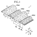
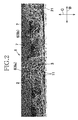
- Fig. 1 is a partial perspective view of a nonwoven fabric 1 according to the present invention and Fig. 2 is a 50-fold magnified photograph exemplarily showing cross-section of the nonwoven fabric.
- the nonwoven fabric 1 has a length direction, a width direction and a thickness direction extending orthogonally one to another and designated by the double-headed arrows A, B and C, respectively.
- the nonwoven fabric 1 has an upper surface 2 and a lower surface 3 opposed to each other in the thickness direction C.
- the upper surface 2 is formed with crests 6 and troughs 7 extending in parallel to one another in the length direction A and undulating in the width direction B.
- the crests 6 include first crests 6a having a height H a and second crests 6b having a height H b in the thickness direction C.
- the height H a of the first crests 6a is larger than the height H b of the second crests 6b.
- These first crests 6a and second crests 6b are arranged alternately in the width dimension B and between each pair of the adjacent first and second crests 6a, 6b, each of the troughs 7 is interposed.
- Such nonwoven fabric 1 is formed by subjecting short fibers (staples) 11 of thermoplastic synthetic resin preferably having a fineness in a range of 1 to 8dtex and a fiber length in a range of 20 to 80mm to blasts of hot air and thereby fusion bonding them to one another.
- the nonwoven fabric 1 is suitable for use as a liquid-pervious inner sheet in a bodily fluid-absorbent wearing article such as disposable diaper or sanitary napkin and, for such intended use, the nonwoven fabric 1 preferably has a basis mass in a range of 18 to 100g/m 2 and preferably has been previously treated to become hydrophilic.
- the nonwoven fabric 1 used as the inner sheet includes a lower surface 3 being substantially flat and an upper surface 2 formed with troughs 7 defining grooves each having a dimension W c in the width direction B in a range of 0.4 to 2mm and first crests 6a defining ridges each having a dimension W a in the width dimension B in a range of 2 to 5mm, which is larger than a dimension W b of second crests 6b in the width dimension B.
- a height H a of the first crests 6a is in a range of 1 to 5mm
- a height H b of the second crests 6b is lower than H a by a range of 0.5 to 2mm
- a level of the troughs 7 is lower than the height H a by a range of 0.7 to 2.5mm.
- each of the short fibers 11 is preferably prepared in the form of a conjugate fiber made of two types of synthetic resin having different fusion temperatures. Such conjugate fibers may be fusion bonded to one another by fusing the component fibers of which fusion temperature is lower than the other.
- component synthetic resin includes, for example, polyethylene/polyester or polyethylene/polypropylene.
- the conjugate fiber may be of core-in-sheath type and side-by-side type.
- the core-in-sheath type conjugate fiber may be concentric core type or eccentric core type.
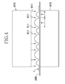
- Fig. 3 is a diagram partially illustrating a process for manufacturing the nonwoven fabric 1 and Fig. 4 is a schematic front elevation view showing a first array of air jet nozzles 910 used in the process of Fig. 3 .
- a conveyor belt 200 which is air-permeable in the thickness direction is loaded with a carded web 100 formed of the short fibers 11 and runs in a machine direction MD.
- the carded web 100 is subjected to blasts of a plurality of hot air jets 921 ejected from a second air jet nozzle array 920 and the air jet 921 is sucked by a suction box 922 through the belt 200.
- the air jet 921 has a temperature not higher than a level to soften the short fibers 11 and serves to compress the carded web 100 to a range of 2/3 to 1/4 of its initial thickness and thereby to stabilize a texture of the carded web 100. Then the carded web 100 is subjected to blasts of a plurality of heated air jets 911 ejected from a first air jet nozzle array 910.
- the air jets 911 has an airflow rate, a pressure and a temperature adjusted so that the short fibers 11 may be moved in a cross direction CD orthogonal to the machine direction MD and may be fusion bonded to one another.
- the first air jet nozzle array 910 includes a plurality of nozzles (not shown) arranged at predetermined pitches a and b in the cross direction CD, from which the air jets 911 are ejected toward the carded web 100. These air jets 911 are sucked by a suction box 915 through the belt 200.
- the positions of the air jets 911 arranged at the pitches a and b in the cross direction CD correspond to the positions of the troughs 7 formed in the nonwoven fabric 1 as shown in Fig. 1 .
- the short fibers 11 located just below the air jets 911 are partially shared half-and-half on both sides about the cross direction CD, respectively, and these portions shared half-and-half participate in formation of the first crests 6a and the second crests 6b while the portions staying immediately below the air jets 911 form the respective troughs 7.
- the short fibers 11 lying between each pair of the adjacent air jets 911 are moved in the cross direction CD to form the first crest 6a or the second crest 6b.
- the short fibers 11 lying between each pair of the adjacent air jets 911 arranged at the relatively large pitch a move to form the first crest 6a and the short fibers 11 lying between each pair of the adjacent air jets 911 arranged at the relatively small pitch b move to form the second crest 6b.
- the first crests 6a formed concurrently with the troughs 7 in this manner have a height larger than a height of the second crests 6b and a density lower than a density of the second crests 6b.
- the short fibers 11 are compressed in the thickness direction C and densified.
- an ejection quantity of the air jets 911 from the first air jet nozzle array 910 may be set to a low level and the second air jet nozzle array 920 may be eliminated.
- the second air jet nozzle array 920 may be used preferably in combination with the first air jet nozzle array 910 to stabilize the carded web 100 in advance.
- a density of the first crests 6a may be adjusted to be lower than a density of the second crests 6b and a density of the second crests 6b may be adjusted to be lower than a density of the troughs 7 to achieve a desirable behavior of the nonwoven fabric 1 when such a nonwoven fabric is used as the liquid-absorbent inner sheet of the bodily fluid-absorbent wearing article.
- bodily fluids excreted on the upper surface 2 of the nonwoven fabric 1 move from the region having a low density toward the region having a high density.
- bodily fluids smoothly move from the first crests 6a toward the troughs 7 and from the second crests 6b toward the troughs 7 in accordance with the density gradient of the nonwoven fabric 1.
- the nonwoven fabric 1 is bent and, in consequence, the first crests 6a and the second crests 6b move closer to each other, bodily fluids move from the first crests 6a toward the second crests 6b. Therefore, certain amount of bodily fluids would not stay in the first crests 6a being first to come in contact with the wearer's skin and would not create a discomfort feeling of wetness against the wearer.
- the density of the first crests 6a remains lower than the density of the second crests 6b. Therefore, even in such a situation, the first crests 6a would not create a discomfort feeling of wetness against the wearer.
- the first crests 6a are compressed together with the second crests 6b, the first crests 6a subjected to a higher degree of compression than that to which the second crests 6b are subjected would not be pressed against the wearer's skin more tightly than the second crests 6b, since the density of the first crests 6a is maintained lower than that of the second crests 6b. Consequently, the texture of the nonwoven fabric would not become uneven and create a discomfort feeling to wear against the wearer.
- TABLE 1 indicates primary manufacturing conditions and evaluation results with respect to the nonwoven fabric 1 as one example of the present invention together with those with respect to comparative examples.
- the nonwoven fabric according to the embodiment indicated in TABLE 1 was manufactured in the equipment exemplarily illustrated in Figs. 3 and 4 without using the second air jet nozzle array 920 under the primary conditions as will be described below.
- the running speed of the carded web 100 was sufficiently low to save use of the second air jet nozzle array 920.
- the nonwoven fabric according to this Comparative Example 1 is similar to the Example according to the present invention in that the crests and the troughs arranged alternately in the cross direction CD but the height of the crests is uniform and there is no discrimination between the first crests and the second crests.
- the nonwoven fabric according to this Comparative Example 2 is similar to the Example according to the present invention in that the crests and the troughs arranged alternately in the cross direction CD and the crests include the first crests and the second crests having a smaller height than a height of the first crests. However, there is not a substantial difference in the height between the first crests and the second crests.
- FIG. 5 schematically illustrating cross-sectional shape of the nonwoven fabric as the example of the present invention taken along in the cross direction CD and (c) of Fig. 5 is a plan view of a pressure plate 22 used in the step (b) of Fig. 5 .
- the nonwoven fabric 1 is placed on a horizontal surface 21 (See Fig. 2 also) in a state free from any external force, i.e., in a non-compressed state wherein this nonwoven fabric 1 is formed with the first crests 6a, the second crests 6b and the troughs 7.
- FIG. 5 schematically illustrating cross-sectional shape of the nonwoven fabric as the example of the present invention taken along in the cross direction CD and (c) of Fig. 5 is a plan view of a pressure plate 22 used in the step (b) of Fig. 5 .
- the nonwoven fabric 1 is placed on a horizontal surface 21 (See Fig. 2 also) in a state free from any external force, i.e., in a non
- the nonwoven fabric 1 was compressed by the pressure plate 22 from above until the first crests 6a are deformed to be substantially flush with the second crests 6b.
- the pressure plate 22 was supported by a pair of supporters 25 having a height substantially the same as the height of the second crests 6b.
- the nonwoven fabric was compressed until the height of the first crests 6a is reduced to 1.45mm.
- the first crest 6a, the second crest 6b and the trough 7 respectively have widths W a , W b and W c and cross-sectional areas S a , S b and S c respectively indicated by shaded portions. A method to measure these cross-sectional areas will be described later with reference to Fig. 6 and the measurement result was indicated in TABLE 1.
- the nonwoven fabric in the non-compressed state was compressed by using the pressure plate 22 shown in Fig. 5 until a height of the crests is reduced to 1.52mm. Also in the nonwoven fabric as the comparative example 1, cross-sectional areas of the crest and the trough in the non-compressed state as well as in the compressed state were measured and the measurement result was indicated in TABLE 1.
- the nonwoven fabric in the non-compressed state was compressed by using the pressure plate 22 until a height of the first crests which is relatively large in the non-compressed state is reduced to a height of the second crests in the non-compressed state, i.e., 1.52mm. Also in the nonwoven fabric as the comparative example 2, cross-sectional areas of the first crest and the second crest in the non-compressed state as well as in the compressed state were measured and the measurement result was indicated in TABLE 1.
- Fig. 6 is a graphic diagram plotting the cross-sectional areas S a , S b and S c of each of the first crests 6a, the second crests 6b and the troughs 7 illustrated in Fig. 5 , respectively, measured by 3D measuring device wherein the first crest 6a was partially illustrated.
- the nonwoven fabric 1 as an object to be measured has its lower surface 3 placed on the horizontal surface 21 and undulation of the upper surface as viewed in a cross-section taken along the cross direction CD was recorded by an outline P.
- High-Accuracy Geometry Measuring System (inclusive of High-Accuracy Stage: KS-1100) and High-Speed and High-Accuracy CCD-Laser Displacement Gauge inclusive of Controller: LK-G3000V Set and Sensor Head: LK-G30) manufactured by Keyence Corporation were used and measuring conditions were set as follows: (Stage: KS-1100) Range of measurement: 3000 ⁇ m x 30000 ⁇ m Measuring pitch: 20 ⁇ m Running speed: 7500 ⁇ m/sec (Measuring Head: LK-G3000V) Measurement mode: Object to be measured Installation mode: Diffuse reflection Filtering: 4 times in average Sampling period: 200 ⁇ m
- the measurement record obtained by the 3D measuring device was processed by Configuration Analysis System KS-H1A (manufactured by Keyence Corporation) to determine heights of the crests, widths of the crests and the troughs and cross-sectional areas of the crests and the troughs.
- Configuration Analysis System KS-H1A manufactured by Keyence Corporation
- respective widths W a , W b and W c of the first crest 6a, the second crest 6b and the trough 7 were determined by a method as follows. Referring to Fig.
- an intersection point X at which an arbitrary horizontal line H z extending in parallel to the horizontal surface 21 intersects with the outline P extending upward from below the horizontal line H z is obtained and, if a segment of the outline segment P extending between a pair of the adjacent intersecting points X lies below the horizontal line H z and a distance between these two intersecting points X is in a range of 0.4 to 2mm, this segment extending between these intersecting points X was defined as the trough 7.
- a region extending between each pair of the adjacent troughs 7 is defined as the crest 6 and, of the adjacent two crests 6, the crest 6 in which a top position of the outline P is relatively high was defined as the first crest 6a and the crest 6 in which a top position of the outline P is relatively low was defined as the second crest 6b.
- each pair of the adjacent intersecting points X spaced from each other by a distance less than 0.4mm was ignored and each pair of the adjacent intersecting points X spaced from each other by a distance of 0.4mm or more was searched. The distance by which each pair of the adjacent intersecting points X are spaced from each other corresponds to the width W c of the trough 7.
- the present invention In the process for manufacturing the nonwoven fabric 1 according to the present invention from the carded web 100, it is not preferable for the present invention to adopt a trough having the width smaller than 0.4mm because it will be difficult to form the first crest 6a and the second crest 6b if the width W c of the trough 7 is narrower than 0.4mm. Also when the width W c exceeds 2mm, it will be difficult to manufacture the nonwoven fabric 1 according to the present invention and, if the nonwoven fabric including the troughs each having such width W c is used as the inner sheet of the bodily fluid-absorbent article, the distance between each pair of the adjacent crests 6 will be too large to assure a desired texture. For this reason, it is not preferable to adopt such excessively wide troughs 7.
- the outline P was plotted by the procedure illustrated in Fig. 6 and thereby the heights H a , H b , the widths W a , W b , W c and the cross-sectional areas S a , S b and S c were measured.
- the pressure plate 22 is formed in its middle region as viewed in the width direction with a slit 26 extending through the pressure plate 22 in its thickness direction.
- This slit 26 allows the 3D measuring device to be operated so that the sensor head of the laser displacement gauge in the 3D measuring device may observe the crests 6 and the troughs 7 of the nonwoven fabric 1 in the course of measuring the heights H a , H b and the width W a , W b , W c in the nonwoven fabric 1 in the compressed state.
- the result obtained from the measurement having been carried out in this manner is recorded in TABLE 1.
- Measurement of the height, the width and the cross-sectional area was carried out also on the nonwoven fabric as comparative examples 1 and 2 in the same manner as in the nonwoven fabric 1 according to the present invention. The result of these measurements is also recorded in TABLE 1.
- Fig. 7 is a 50-fold magnified photograph exemplarily showing a cross-section of the second crest 6b cut in the cross direction CD.
- the cut surface was obtained by cutting the nonwoven fabric 1 in the cross direction CD using a sharp cutter, for example, the substitute edge H-100 for KOKUYO Cutter Knife HA-B (trade name). This cut surface was photographed at 50-fold magnifications by using Real Surface View-VE-7800 manufactured by Keyence Corporation. Cross-sections 11a of the short fibers 11 appear in this photograph of the cross-section obtained in this manner.
- the number of the cross-sections 11a (i.e., the number of fiber cross-sections) was determined with respect to the first crests 6a, the second crests 6b and the troughs 7, then respective ratios between these numbers and the cross-sectional areas of the first crests 6a, the second crests 6b and the troughs 7 were determined and the respective values of these ratios were defined as the respective fiber densities of the first crests 6a, the second crests 6b and the troughs 7 in the compressed state and in the non-compressed state.
- these fiber densities are referred to also as fiber density indices.
- TABLE 1 indicates the fiber density indices in the example of the present invention and the comparative examples 1 and 2.
- the fiber density indices of the nonwoven fabric in the example of the present invention gradually increased in the order of the first crests 6a, the second crests 6b and the troughs 7. Such gradient of the fiber density indices was not changed in the compressed state also.
- the fiber density of the first crests 6a remains lower than that of the second crests 6b and therefore bodily fluids excreted on the upper surface 2 of the nonwoven fabric 1 may smoothly move from the first crests 6a having a relatively low density to the second crests 6b and the troughs 7 having a relatively high density.
- nonwoven fabric 1 When such a nonwoven fabric 1 is used as an inner sheet of an absorbent article of such as, for example, a disposable diaper, the nonwoven fabric 1 allows bodily fluids to move quickly from the upper surface 2 toward the lower surface 3 and this capacity can be represented, for example, by the strike-through value or Q-Max value.
- the strike-through value used herein is represented by a time (unit: sec) required for 10ml of artificial urine to pass through the nonwoven fabric in the form of a test piece for measurement and the smaller the strike-through value, the sooner the permeation.
- the tester LISTER manufactured by Lenzingtechnik Corporation was used. Specifically, the measuring probe was placed on the nonwoven fabric and the tester was operated in accordance with EDANA-ERT Section 150.3 liquid strike-though time method prescribed for this tester. Under the nonwoven fabric, 20 sheets of filter paper (Qualitative filter paper No. 2 manufactured by ADVANTEC MFS., INC.) were stacked in substitution for the absorbent article.
- the artificial urine was prepared by dissolving 200g of urea, 80g of sodium chloride, 8g of magnesium sulfate, 3g of calcium chloride and 1g of blue pigment No. 1 in 10 liter of ion-exchange water and 72mN/m of this artificial urine was used at a temperature of 20°C. Result of measurement was indicated in TABLE 1. The strike-through values measured on the comparative examples 1 and 2 were also indicated in TABLE 1.
- the Q-Max value corresponds to a quantified heat quantity drawn from the wearer's skin by the inner sheet when the inner sheet wetted with bodily fluids comes in contact with the wearer's skin represented by unit of J/cm 2 *sec.
- KES-F7-THERMOLABO II Model high-accuracy and high-speed thermal property measuring device manufactured by KATO TECH CO., LTD. was used.
- a temperature of the probe was set to ⁇ room temperature + 10°C, Q-Max measurement (cool sensitivity measurement)> and as the surface temperature of the probe, two standard levels of 10g/cm 2 and 30g/cm 2 were adopted.
- the nonwoven fabric for measurement 10 x 10 cm was used and this nonwoven fabric was placed on 3 sheets of qualitative filter paper No. 2 stacked, a cylinder having an inner diameter of 20mm was placed on the nonwoven fabric and 10cc of the artificial urine was poured into this cylinder about 5 sec, then the cylinder was removed, 20 sec after the artificial urine had been poured, the probe was put in contact with the surface of the nonwoven fabric to measure a heat transfer from the probe to the surface of the nonwoven fabric. Result of measurement was indicated in TABLE 1. As will be apparent from comparison of the example of the invention with the comparative examples, the nonwoven fabric 1 free from possibility that bodily fluids might stay on the surface 2 exhibited a relatively small Q-Max value.
Landscapes
- Health & Medical Sciences (AREA)
- Engineering & Computer Science (AREA)
- Textile Engineering (AREA)
- Vascular Medicine (AREA)
- Biomedical Technology (AREA)
- Heart & Thoracic Surgery (AREA)
- Epidemiology (AREA)
- Life Sciences & Earth Sciences (AREA)
- Animal Behavior & Ethology (AREA)
- General Health & Medical Sciences (AREA)
- Public Health (AREA)
- Veterinary Medicine (AREA)
- Nonwoven Fabrics (AREA)
- Absorbent Articles And Supports Therefor (AREA)
Abstract
Description
- The present invention relates to nonwoven fabrics formed of short fibers of thermoplastic synthetic resin.
- It is conventionally known to fusion bond short fibers of thermoplastic synthetic resin together and thereby to obtain nonwoven fabrics. As an example of such nonwoven fabrics,
JP 2008-25080 A - {PTL 1}
JP 2008-25080 A - The ridges in the nonwoven fabric disclosed in PTL 1 include the relatively high ridges and the relatively low ridges. The relatively high ridges and the relatively low ridge are formed to be the same in their basis mass wherein the basis mass of both these ridges having different height dimensions in the middle segments thereof in the width direction than the basis mass of the grooves. Assuming that such a nonwoven fabric is used as the liquid-pervious inner sheet in the wearing article such as a disposable diaper or a menstruation napkin and comes in tight contact with the wearer's skin, the relatively high ridges are primarily compressed. In the inner sheet at this moment, the compressed ridges have the density thereof further increased and, in consequence, bodily fluids are apt to stay in these ridges and barred from smoothly moving toward the surrounding region of the lower density. When the ridges are compressed, for example, to the same level with the relatively low ridges, the ridges having been compressed in this manner will locally pressed against the wearer's skin. Eventually, the inner sheet as a whole may not come in soft and close contact with the wearer's skin and may have an uncomfortable texture.
- An object of this invention is to provide a nonwoven fabric improved so that even when the nonwoven fabric is formed on its upper surface with the ridges and the grooves, bodily fluids excreted onto the upper surface may not stay in these ridges after this upper surface has come in close contact with the wearer's skin.
- According to the present invention, there is provided a nonwoven fabric formed of short fibers of thermoplastic synthetic resin fusion bonded to one another and having a length direction, a width direction and a thickness direction extending orthogonally one to another, including an upper surface and a lower surface opposed to the upper surface as viewed in the thickness direction wherein
the upper surface is formed with crests and troughs undulating in the width direction and extending in parallel to one another in the length direction and
the crests include first crests having a uniform height dimension and second crests having a uniform height dimension measured from the lower surface wherein the height dimension of the first crests is larger than the height dimension of the second crests. - The present invention resides in that a density of the nonwoven fabric gradually increases in order of the first crests, the second crests and the troughs and the density of the first crests remains lower than the density of the second crests even when the first crests are compressed from the upper surface toward the lower surface until the first crests become flush with the second crests.
- According to one embodiment of the present invention, the nonwoven fabric has a basis weight in a range of 18 to 100g/m2 and each of the short fibers has a fineness in a range of 1 to 8dtex and a fiber length in a range of 20 to 80mm, and the nonwoven fabric has been modified to become hydrophilic.
- According to another embodiment of the present invention, the short fibers are conjugate fibers including two types of the thermoplastic synthetic resin having different fusion temperatures and these two types of the thermoplastic synthetic resin are fusion bonded to each other via one of the thermoplastic synthetic resins having a lower fusion temperature.
- According to still another embodiment of the present invention, the height dimension of the first crests is in a range of 1 to 5mm and the height dimension of the second crests is lower than the height dimension of the first crests by a range of 0.5 to 2mm.
- According to yet another embodiment of the present invention, the first crests and the second crests are formed alternately in the width direction and each of the troughs is interposed between each pair of the adjacent first crest and second crest.
- A measuring method used for measuring "density of nonwoven fabric" will be described later with reference to
Figs. 5 through 7 . - The nonwoven fabric according to the present invention has the crests and the troughs extending in parallel to one another in the length direction wherein the crests include the first crests each having a uniform height dimension and the second crests each having a uniform height dimension which is smaller than the height dimension of the first crests wherein both of the height dimensions are defined by a dimension of the nonwoven fabric in the thickness direction and these crests cooperate with the troughs to form the upper surface of the nonwoven fabric with the ridges and the grooves. The density of the nonwoven fabric gradually increases in the order of the first crest, the second crest and the trough wherein the density of the first crest is maintained lower than the density of the second crest even when the first crest is compressed to the same level as the second crest. On the assumption that such a nonwoven fabric is used as the inner sheet of the wearing article, even when the upper surface of the nonwoven fabric comes in close contact with the wearer's skin and the first crests having initially been highest are compressed to the same level as the second crests, the density gradient of the first crests, the second crests and the troughs is maintained. In principle, bodily fluids excreted onto the inner sheet are apt to flow from the region having the relatively low density toward the region having the relatively high density, specifically, from the first crests to the second crests, then from the second crest to the troughs. The stabilized density gradient assures that bodily fluids smoothly flow toward the troughs without staying in the first crests and the wearer is free from discomfort feeling of wetness even if the first crests directly come in contact with the wearer's skin. In addition, the first crests would not locally press against the wearer's skin since the density of the first crests remains lower than that of the second crests. In other words, the nonwoven fabric according to the present invention has a uniform texture.
-
- {
Fig. 1} Fig. 1 is a partial perspective view of a nonwoven fabric according to the present invention. - {
Fig. 2} Fig. 2 is a photograph of a section of the nonwoven fabric in a cross direction. - {
Fig. 3} Fig. 3 is a diagram partially illustrating a process for manufacturing the nonwoven fabric. - {
Fig. 4} Fig. 4 is a schematic front elevation view showing a first array of air jet nozzles. - {
Fig. 5} Fig. 5 is a diagram illustrating how the section of the nonwoven fabric is transformed. - {
Fig. 6} Fig. 6 is a graphic diagram plotting the surface contour of the nonwoven fabric based on observation. - {
Fig. 7} Fig. 7 is a photograph showing a cross-section of fibers. - Details of nonwoven fabrics according to the present invention will be more fully understood from the description given hereunder with reference to the accompanying drawings.
-
Fig. 1 is a partial perspective view of a nonwoven fabric 1 according to the present invention andFig. 2 is a 50-fold magnified photograph exemplarily showing cross-section of the nonwoven fabric. It should be noted here that the photograph ofFig. 2 is really an assembly including a plurality of photographs joined one with another in a width direction since it is impossible to record the 50-fold magnified photograph of the nonwoven fabric over its sufficiently wide range in a single shot. The nonwoven fabric 1 has a length direction, a width direction and a thickness direction extending orthogonally one to another and designated by the double-headed arrows A, B and C, respectively. The nonwoven fabric 1 has anupper surface 2 and alower surface 3 opposed to each other in the thickness direction C. Theupper surface 2 is formed withcrests 6 andtroughs 7 extending in parallel to one another in the length direction A and undulating in the width direction B. Thecrests 6 includefirst crests 6a having a height Ha andsecond crests 6b having a height Hb in the thickness direction C. The height Ha of thefirst crests 6a is larger than the height Hb of thesecond crests 6b. Thesefirst crests 6a andsecond crests 6b are arranged alternately in the width dimension B and between each pair of the adjacent first andsecond crests troughs 7 is interposed. - Such nonwoven fabric 1 is formed by subjecting short fibers (staples) 11 of thermoplastic synthetic resin preferably having a fineness in a range of 1 to 8dtex and a fiber length in a range of 20 to 80mm to blasts of hot air and thereby fusion bonding them to one another. The nonwoven fabric 1 is suitable for use as a liquid-pervious inner sheet in a bodily fluid-absorbent wearing article such as disposable diaper or sanitary napkin and, for such intended use, the nonwoven fabric 1 preferably has a basis mass in a range of 18 to 100g/m2 and preferably has been previously treated to become hydrophilic. The nonwoven fabric 1 used as the inner sheet includes a
lower surface 3 being substantially flat and anupper surface 2 formed withtroughs 7 defining grooves each having a dimension Wc in the width direction B in a range of 0.4 to 2mm andfirst crests 6a defining ridges each having a dimension Wa in the width dimension B in a range of 2 to 5mm, which is larger than a dimension Wb ofsecond crests 6b in the width dimension B. Preferably, a height Ha of thefirst crests 6a is in a range of 1 to 5mm, a height Hb of thesecond crests 6b is lower than Ha by a range of 0.5 to 2mm and a level of thetroughs 7 is lower than the height Ha by a range of 0.7 to 2.5mm. To facilitate theshort fibers 11 to be fusion bonded to one another and to make the nonwoven fabric 1 elastically compressible in the thickness direction C, each of theshort fibers 11 is preferably prepared in the form of a conjugate fiber made of two types of synthetic resin having different fusion temperatures. Such conjugate fibers may be fusion bonded to one another by fusing the component fibers of which fusion temperature is lower than the other. Combination of these different types of component synthetic resin includes, for example, polyethylene/polyester or polyethylene/polypropylene. The conjugate fiber may be of core-in-sheath type and side-by-side type. The core-in-sheath type conjugate fiber may be concentric core type or eccentric core type. -
Fig. 3 is a diagram partially illustrating a process for manufacturing the nonwoven fabric 1 andFig. 4 is a schematic front elevation view showing a first array ofair jet nozzles 910 used in the process ofFig. 3 . Referring toFig. 3 , aconveyor belt 200 which is air-permeable in the thickness direction is loaded with a cardedweb 100 formed of theshort fibers 11 and runs in a machine direction MD. The cardedweb 100 is subjected to blasts of a plurality ofhot air jets 921 ejected from a second airjet nozzle array 920 and theair jet 921 is sucked by asuction box 922 through thebelt 200. Theair jet 921 has a temperature not higher than a level to soften theshort fibers 11 and serves to compress the cardedweb 100 to a range of 2/3 to 1/4 of its initial thickness and thereby to stabilize a texture of the cardedweb 100. Then the cardedweb 100 is subjected to blasts of a plurality of heatedair jets 911 ejected from a first airjet nozzle array 910. Theair jets 911 has an airflow rate, a pressure and a temperature adjusted so that theshort fibers 11 may be moved in a cross direction CD orthogonal to the machine direction MD and may be fusion bonded to one another. - Referring to
Fig. 4 , the first airjet nozzle array 910 includes a plurality of nozzles (not shown) arranged at predetermined pitches a and b in the cross direction CD, from which theair jets 911 are ejected toward the cardedweb 100. Theseair jets 911 are sucked by asuction box 915 through thebelt 200. The positions of theair jets 911 arranged at the pitches a and b in the cross direction CD correspond to the positions of thetroughs 7 formed in the nonwoven fabric 1 as shown inFig. 1 . In the cardedweb 100, theshort fibers 11 located just below theair jets 911 are partially shared half-and-half on both sides about the cross direction CD, respectively, and these portions shared half-and-half participate in formation of thefirst crests 6a and thesecond crests 6b while the portions staying immediately below theair jets 911 form therespective troughs 7. Theshort fibers 11 lying between each pair of theadjacent air jets 911 are moved in the cross direction CD to form thefirst crest 6a or thesecond crest 6b. Specifically, theshort fibers 11 lying between each pair of theadjacent air jets 911 arranged at the relatively large pitch a move to form thefirst crest 6a and theshort fibers 11 lying between each pair of theadjacent air jets 911 arranged at the relatively small pitch b move to form thesecond crest 6b. Thefirst crests 6a formed concurrently with thetroughs 7 in this manner have a height larger than a height of thesecond crests 6b and a density lower than a density of thesecond crests 6b. In thetroughs 7 formed immediately below therespective air jets 911, theshort fibers 11 are compressed in the thickness direction C and densified. - When manufacturing the nonwoven fabric 1 by using the process illustrated in
Figs. 3 and4 , assuming that the cardedweb 100, for example, having a basis mass in a range of 30 to 50g/m2 is conveyed in the machine direction MD at a moderate speed, for example, at a speed in the order of 10m/min, an ejection quantity of theair jets 911 from the first airjet nozzle array 910 may be set to a low level and the second airjet nozzle array 920 may be eliminated. On the assumption that such cardedweb 100 is conveyed at a speed in a range of 30 to 40m/min, the second airjet nozzle array 920 may be used preferably in combination with the first airjet nozzle array 910 to stabilize the cardedweb 100 in advance. - In the nonwoven fabric 1 of
Fig. 1 obtained in this manner, a density of thefirst crests 6a may be adjusted to be lower than a density of thesecond crests 6b and a density of thesecond crests 6b may be adjusted to be lower than a density of thetroughs 7 to achieve a desirable behavior of the nonwoven fabric 1 when such a nonwoven fabric is used as the liquid-absorbent inner sheet of the bodily fluid-absorbent wearing article. Specifically, bodily fluids excreted on theupper surface 2 of the nonwoven fabric 1 move from the region having a low density toward the region having a high density. In other words, bodily fluids smoothly move from thefirst crests 6a toward thetroughs 7 and from thesecond crests 6b toward thetroughs 7 in accordance with the density gradient of the nonwoven fabric 1. When the nonwoven fabric 1 is bent and, in consequence, thefirst crests 6a and thesecond crests 6b move closer to each other, bodily fluids move from thefirst crests 6a toward thesecond crests 6b. Therefore, certain amount of bodily fluids would not stay in thefirst crests 6a being first to come in contact with the wearer's skin and would not create a discomfort feeling of wetness against the wearer. In addition, even when the nonwoven fabric 1 is compressed until thefirst crests 6a are compressed to the same level with thesecond crests 6b, the density of thefirst crests 6a remains lower than the density of thesecond crests 6b. Therefore, even in such a situation, thefirst crests 6a would not create a discomfort feeling of wetness against the wearer. Also, even when thefirst crests 6a are compressed together with thesecond crests 6b, thefirst crests 6a subjected to a higher degree of compression than that to which thesecond crests 6b are subjected would not be pressed against the wearer's skin more tightly than thesecond crests 6b, since the density of thefirst crests 6a is maintained lower than that of thesecond crests 6b. Consequently, the texture of the nonwoven fabric would not become uneven and create a discomfort feeling to wear against the wearer. - TABLE 1 indicates primary manufacturing conditions and evaluation results with respect to the nonwoven fabric 1 as one example of the present invention together with those with respect to comparative examples.
- The nonwoven fabric according to the embodiment indicated in TABLE 1 was manufactured in the equipment exemplarily illustrated in
Figs. 3 and4 without using the second airjet nozzle array 920 under the primary conditions as will be described below. In this embodiment, the running speed of the cardedweb 100 was sufficiently low to save use of the second airjet nozzle array 920. - (1) Short fiber (staple): core-in-sheath type conjugate fiber having fineness in a range of 2.6 to 3.3dtex, a fiber length in a range of 38 to 51mm, polyester as the core component and polyethylene as the sheath component.
- (2) Carded web: basis mass of 35g/m2 and running speed of 10m/min in the machine direction.
- (3) First air jet nozzle array: nozzle diameter of 1mm, nozzle pitch a = 4mm, nozzle pitch b = 2.5mm, distance between nozzle and conveyor belt of 5mm, air jet pressure of 0.06MPa and air temperature of 140°C.
- The nonwoven fabric indicated in TABLE 1 as Comparative Example 1 was obtained in the same manufacturing conditions as those for the Example according to the present invention except the nozzle pitches, i.e., set to a = 4mm and b = 4mm. The nonwoven fabric according to this Comparative Example 1 is similar to the Example according to the present invention in that the crests and the troughs arranged alternately in the cross direction CD but the height of the crests is uniform and there is no discrimination between the first crests and the second crests.
- The nonwoven fabric indicated in TABLE 1 as Comparative Example 2 was obtained in the same manufacturing conditions as those for the Example according to the present invention except the nozzle pitches, i.e., set to a = 3.5mm and b = 3mm. The nonwoven fabric according to this Comparative Example 2 is similar to the Example according to the present invention in that the crests and the troughs arranged alternately in the cross direction CD and the crests include the first crests and the second crests having a smaller height than a height of the first crests. However, there is not a substantial difference in the height between the first crests and the second crests.
-
{TABLE 1} Example Comparative Example 1 Comparative Example 2 1 st Crest 2nd Crest Trough Crest Trough 1st Crest 2nd Crest Trough Non-Compressed state Height (mm) 2.43 1.45 — 2.07 — 1.91 1.53 — Width (mm) 3.81 2.08 0.56 3.52 0.44 2.82 2.17 0.62 Sectional area (mm2) 5.71 1.78 0.16 4.03 0.13 3.31 2.13 0.17 Number of fiber's cross-sections 248.3 147.3 25.3 230.7 23 220 179.3 28 Fiber's density index (number/mm2) 43.5 82.8 158.1 57.2 176.9 66.5 84.2 164.7 Compressed state Height (mm) 1.52 1.50 — 1.52 — 1.53 1.55 — width (mm) 3.80 1.99 0.56 3.48 0.46 2.77 2.19 0.64 Sectional area (mm2) 5.07 1.73 0.16 3.59 0.16 1.77 2.10 0.15 Number of fiber's cross-sections 248.3 147.3 25.3 230.7 23 220 179.3 28 Fiber's density index (number/mm2) 49.0 85.1 158.1 64.3 143.8 124.3 85.4 186.7 Strike-through value (sec) 1.61 2.16 1.96 Q-Max value (J/cm2•sec) Load of 10g/cm2 0.178 0.373 0.366 Load of 30g/cm2 0.819 1.027 0.863 - (a) and (b) of
Fig. 5 schematically illustrating cross-sectional shape of the nonwoven fabric as the example of the present invention taken along in the cross direction CD and (c) ofFig. 5 is a plan view of apressure plate 22 used in the step (b) ofFig. 5 . In (a) ofFig. 5 , the nonwoven fabric 1 is placed on a horizontal surface 21 (SeeFig. 2 also) in a state free from any external force, i.e., in a non-compressed state wherein this nonwoven fabric 1 is formed with thefirst crests 6a, thesecond crests 6b and thetroughs 7. In (b) ofFig. 5 , the nonwoven fabric 1 was compressed by thepressure plate 22 from above until thefirst crests 6a are deformed to be substantially flush with thesecond crests 6b. Thepressure plate 22 was supported by a pair ofsupporters 25 having a height substantially the same as the height of thesecond crests 6b. In the example of the present invention wherein thefirst crests 6a have a height of 2.43mm and thesecond crests 6b have a height of 1.45mm, the nonwoven fabric was compressed until the height of thefirst crests 6a is reduced to 1.45mm. Thefirst crest 6a, thesecond crest 6b and thetrough 7 respectively have widths Wa, Wb and Wc and cross-sectional areas Sa, Sb and Sc respectively indicated by shaded portions. A method to measure these cross-sectional areas will be described later with reference toFig. 6 and the measurement result was indicated in TABLE 1. - In the nonwoven fabric as the comparative example 1, the nonwoven fabric in the non-compressed state was compressed by using the
pressure plate 22 shown inFig. 5 until a height of the crests is reduced to 1.52mm. Also in the nonwoven fabric as the comparative example 1, cross-sectional areas of the crest and the trough in the non-compressed state as well as in the compressed state were measured and the measurement result was indicated in TABLE 1. - In the nonwoven fabric as the comparative example 2, the nonwoven fabric in the non-compressed state was compressed by using the
pressure plate 22 until a height of the first crests which is relatively large in the non-compressed state is reduced to a height of the second crests in the non-compressed state, i.e., 1.52mm. Also in the nonwoven fabric as the comparative example 2, cross-sectional areas of the first crest and the second crest in the non-compressed state as well as in the compressed state were measured and the measurement result was indicated in TABLE 1. -
Fig. 6 is a graphic diagram plotting the cross-sectional areas Sa, Sb and Sc of each of thefirst crests 6a, thesecond crests 6b and thetroughs 7 illustrated inFig. 5 , respectively, measured by 3D measuring device wherein thefirst crest 6a was partially illustrated. The nonwoven fabric 1 as an object to be measured has itslower surface 3 placed on thehorizontal surface 21 and undulation of the upper surface as viewed in a cross-section taken along the cross direction CD was recorded by an outline P. As 3D measuring device, High-Accuracy Geometry Measuring System (inclusive of High-Accuracy Stage: KS-1100) and High-Speed and High-Accuracy CCD-Laser Displacement Gauge inclusive of Controller: LK-G3000V Set and Sensor Head: LK-G30) manufactured by Keyence Corporation were used and measuring conditions were set as follows:
(Stage: KS-1100)
Range of measurement: 3000µm x 30000µm
Measuring pitch: 20µm
Running speed: 7500µm/sec
(Measuring Head: LK-G3000V)
Measurement mode: Object to be measured
Installation mode: Diffuse reflection
Filtering: 4 times in average
Sampling period: 200µm - The measurement record obtained by the 3D measuring device was processed by Configuration Analysis System KS-H1A (manufactured by Keyence Corporation) to determine heights of the crests, widths of the crests and the troughs and cross-sectional areas of the crests and the troughs. Referring to
Fig. 6 , respective widths Wa, Wb and Wc of thefirst crest 6a, thesecond crest 6b and thetrough 7 were determined by a method as follows. Referring toFig. 6 , an intersection point X at which an arbitrary horizontal line Hz extending in parallel to thehorizontal surface 21 intersects with the outline P extending upward from below the horizontal line Hz is obtained and, if a segment of the outline segment P extending between a pair of the adjacent intersecting points X lies below the horizontal line Hz and a distance between these two intersecting points X is in a range of 0.4 to 2mm, this segment extending between these intersecting points X was defined as thetrough 7. A region extending between each pair of theadjacent troughs 7 is defined as thecrest 6 and, of the adjacent twocrests 6, thecrest 6 in which a top position of the outline P is relatively high was defined as thefirst crest 6a and thecrest 6 in which a top position of the outline P is relatively low was defined as thesecond crest 6b. It should be noted here that each pair of the adjacent intersecting points X spaced from each other by a distance less than 0.4mm was ignored and each pair of the adjacent intersecting points X spaced from each other by a distance of 0.4mm or more was searched. The distance by which each pair of the adjacent intersecting points X are spaced from each other corresponds to the width Wc of thetrough 7. In the process for manufacturing the nonwoven fabric 1 according to the present invention from the cardedweb 100, it is not preferable for the present invention to adopt a trough having the width smaller than 0.4mm because it will be difficult to form thefirst crest 6a and thesecond crest 6b if the width Wc of thetrough 7 is narrower than 0.4mm. Also when the width Wc exceeds 2mm, it will be difficult to manufacture the nonwoven fabric 1 according to the present invention and, if the nonwoven fabric including the troughs each having such width Wc is used as the inner sheet of the bodily fluid-absorbent article, the distance between each pair of theadjacent crests 6 will be too large to assure a desired texture. For this reason, it is not preferable to adopt such excessivelywide troughs 7. - With respect also to the nonwoven fabric 1 compressed by the
pressure plate 22 until thefirst crests 6a are compressed downward to the state as illustrated in (b) ofFig. 5 , the outline P was plotted by the procedure illustrated inFig. 6 and thereby the heights Ha, Hb, the widths Wa, Wb, Wc and the cross-sectional areas Sa, Sb and Sc were measured. Referring to (c) ofFig. 5 , thepressure plate 22 is formed in its middle region as viewed in the width direction with aslit 26 extending through thepressure plate 22 in its thickness direction. This slit 26 allows the 3D measuring device to be operated so that the sensor head of the laser displacement gauge in the 3D measuring device may observe thecrests 6 and thetroughs 7 of the nonwoven fabric 1 in the course of measuring the heights Ha, Hb and the width Wa, Wb, Wc in the nonwoven fabric 1 in the compressed state. The result obtained from the measurement having been carried out in this manner is recorded in TABLE 1. Measurement of the height, the width and the cross-sectional area was carried out also on the nonwoven fabric as comparative examples 1 and 2 in the same manner as in the nonwoven fabric 1 according to the present invention. The result of these measurements is also recorded in TABLE 1. -
Fig. 7 is a 50-fold magnified photograph exemplarily showing a cross-section of thesecond crest 6b cut in the cross direction CD. The cut surface was obtained by cutting the nonwoven fabric 1 in the cross direction CD using a sharp cutter, for example, the substitute edge H-100 for KOKUYO Cutter Knife HA-B (trade name). This cut surface was photographed at 50-fold magnifications by using Real Surface View-VE-7800 manufactured by Keyence Corporation. Cross-sections 11a of theshort fibers 11 appear in this photograph of the cross-section obtained in this manner. According to the present invention, the number of thecross-sections 11a (i.e., the number of fiber cross-sections) was determined with respect to thefirst crests 6a, thesecond crests 6b and thetroughs 7, then respective ratios between these numbers and the cross-sectional areas of thefirst crests 6a, thesecond crests 6b and thetroughs 7 were determined and the respective values of these ratios were defined as the respective fiber densities of thefirst crests 6a, thesecond crests 6b and thetroughs 7 in the compressed state and in the non-compressed state. In this invention, these fiber densities are referred to also as fiber density indices. TABLE 1 indicates the fiber density indices in the example of the present invention and the comparative examples 1 and 2. As will be apparent from TABLE 1, the fiber density indices of the nonwoven fabric in the example of the present invention, the fiber density indices of the nonwoven fabric in the non-compressed state gradually increased in the order of thefirst crests 6a, thesecond crests 6b and thetroughs 7. Such gradient of the fiber density indices was not changed in the compressed state also. Specifically, in the nonwoven fabric according to the present invention, even when thefirst crests 6a are compressed to the same level as thesecond crests 6b, the fiber density of thefirst crests 6a remains lower than that of thesecond crests 6b and therefore bodily fluids excreted on theupper surface 2 of the nonwoven fabric 1 may smoothly move from thefirst crests 6a having a relatively low density to thesecond crests 6b and thetroughs 7 having a relatively high density. - When such a nonwoven fabric 1 is used as an inner sheet of an absorbent article of such as, for example, a disposable diaper, the nonwoven fabric 1 allows bodily fluids to move quickly from the
upper surface 2 toward thelower surface 3 and this capacity can be represented, for example, by the strike-through value or Q-Max value. - The strike-through value used herein is represented by a time (unit: sec) required for 10ml of artificial urine to pass through the nonwoven fabric in the form of a test piece for measurement and the smaller the strike-through value, the sooner the permeation. To measure the strike-through value, the tester LISTER manufactured by Lenzing Technik Corporation was used. Specifically, the measuring probe was placed on the nonwoven fabric and the tester was operated in accordance with EDANA-ERT Section 150.3 liquid strike-though time method prescribed for this tester. Under the nonwoven fabric, 20 sheets of filter paper (Qualitative filter paper No. 2 manufactured by ADVANTEC MFS., INC.) were stacked in substitution for the absorbent article. The artificial urine was prepared by dissolving 200g of urea, 80g of sodium chloride, 8g of magnesium sulfate, 3g of calcium chloride and 1g of blue pigment No. 1 in 10 liter of ion-exchange water and 72mN/m of this artificial urine was used at a temperature of 20°C. Result of measurement was indicated in TABLE 1. The strike-through values measured on the comparative examples 1 and 2 were also indicated in TABLE 1.
- The Q-Max value corresponds to a quantified heat quantity drawn from the wearer's skin by the inner sheet when the inner sheet wetted with bodily fluids comes in contact with the wearer's skin represented by unit of J/cm2*sec. The higher the Q-Max value of the inner sheet is, the larger the heat quantity drawn from the wearer's skin becomes and, in consequence, the wearer experiences an abrupt cold sensation. To measure the Q-Max value, KES-F7-THERMOLABO II Model high-accuracy and high-speed thermal property measuring device manufactured by KATO TECH CO., LTD. was used. As the measuring conditions, a temperature of the probe was set to <room temperature + 10°C, Q-Max measurement (cool sensitivity measurement)> and as the surface temperature of the probe, two standard levels of 10g/cm2 and 30g/cm2 were adopted. As the nonwoven fabric for measurement, 10 x 10 cm was used and this nonwoven fabric was placed on 3 sheets of qualitative filter paper No. 2 stacked, a cylinder having an inner diameter of 20mm was placed on the nonwoven fabric and 10cc of the artificial urine was poured into this cylinder about 5 sec, then the cylinder was removed, 20 sec after the artificial urine had been poured, the probe was put in contact with the surface of the nonwoven fabric to measure a heat transfer from the probe to the surface of the nonwoven fabric. Result of measurement was indicated in TABLE 1. As will be apparent from comparison of the example of the invention with the comparative examples, the nonwoven fabric 1 free from possibility that bodily fluids might stay on the
surface 2 exhibited a relatively small Q-Max value. -
- 1
- nonwoven fabric
- 2
- upper surface
- 3
- lower surface
- 6
- crest
- 6a
- crest (first crest)
- 6b
- crest (second crest)
- 7
- troughs
- 11
- short fibers
- A
- length direction
- B
- width direction
- C
- thickness direction
Claims (5)
- A nonwoven fabric formed of short fibers of thermoplastic synthetic resin fusion bonded to one another and having a length direction, a width direction and a thickness direction extending orthogonally to one another, including an upper surface and a lower surface opposed to the upper surface as viewed in the thickness direction wherein
the upper surface is formed with crests and troughs undulating in the width direction and extending in parallel to one another in the length direction and
the crests comprise first crests having a uniform height dimension and second crests having a uniform height dimension measured from the lower surface wherein the height dimension of the first crests is larger than the height dimension of the second crests, wherein:density of the nonwoven fabric gradually increases in order of the first crests, the second crests and the troughs and the density of the first crests remains lower than the density of the second crests even when the first crests are compressed from the upper surface toward the lower surface until the first crests become flush with the second crests. - The nonwoven fabric defined by Claim 1, wherein the nonwoven fabric has a basis weight in a range of 18 to 100g/m2 and each of the short fibers has a fineness in a range of 1 to 8dtex and a fiber length in a range of 20 to 80mm, and wherein the nonwoven fabric has been modified to become hydrophilic.
- The nonwoven fabric defined by Claim 1 or 2, wherein the short fibers are conjugate fibers comprising two types of the thermoplastic synthetic resin having different fusion temperatures and these two types of the thermoplastic synthetic resin are fusion bonded to each other via one of the thermoplastic synthetic resins having a lower fusion temperature.
- The nonwoven fabric defined by any one of Claims 1 through 3, wherein the height dimension of the first crests is in a range of 1 to 5mm and the height dimension of the second crests is lower than the height dimension of the first crests by a range of 0.5 to 2mm.
- The nonwoven fabric defined by any one of Claims 1 through 4, wherein the first crests and the second crests are formed alternately in the width direction and each of the troughs is interposed between each pair of the adjacent the first crest and the second crest.
Applications Claiming Priority (2)
| Application Number | Priority Date | Filing Date | Title |
|---|---|---|---|
| JP2009235513A JP5421720B2 (en) | 2009-10-09 | 2009-10-09 | Non-woven |
| PCT/JP2010/066134 WO2011043180A1 (en) | 2009-10-09 | 2010-09-17 | Nonwoven fabric |
Publications (2)
| Publication Number | Publication Date |
|---|---|
| EP2487285A1 true EP2487285A1 (en) | 2012-08-15 |
| EP2487285A4 EP2487285A4 (en) | 2013-09-11 |
Family
ID=43856650
Family Applications (1)
| Application Number | Title | Priority Date | Filing Date |
|---|---|---|---|
| EP10821851.2A Withdrawn EP2487285A4 (en) | 2009-10-09 | 2010-09-17 | Nonwoven fabric |
Country Status (9)
| Country | Link |
|---|---|
| US (1) | US20120196091A1 (en) |
| EP (1) | EP2487285A4 (en) |
| JP (1) | JP5421720B2 (en) |
| KR (1) | KR101507647B1 (en) |
| CN (1) | CN102575395A (en) |
| AR (1) | AR078570A1 (en) |
| MY (1) | MY168864A (en) |
| TW (1) | TW201129742A (en) |
| WO (1) | WO2011043180A1 (en) |
Cited By (2)
| Publication number | Priority date | Publication date | Assignee | Title |
|---|---|---|---|---|
| EP3187161A4 (en) * | 2014-08-29 | 2017-08-16 | Daio Paper Corporation | Absorbent article |
| EP3877073A4 (en) * | 2018-11-05 | 2023-06-28 | Hollingsworth & Vose Company | Filter media with irregular structure |
Families Citing this family (56)
| Publication number | Priority date | Publication date | Assignee | Title |
|---|---|---|---|---|
| JP4996766B2 (en) * | 2010-11-30 | 2012-08-08 | ユニ・チャーム株式会社 | Liquid-permeable sheet and method for producing the same |
| TWI448277B (en) | 2011-03-31 | 2014-08-11 | Uni Charm Corp | Absorbent items |
| JP5642009B2 (en) * | 2011-04-01 | 2014-12-17 | ユニ・チャーム株式会社 | Nonwoven fabric, absorbent article containing the nonwoven fabric, and method for producing the nonwoven fabric |
| JP5361965B2 (en) | 2011-04-28 | 2013-12-04 | ユニ・チャーム株式会社 | Absorbent articles |
| JP6092508B2 (en) * | 2011-09-30 | 2017-03-08 | ユニ・チャーム株式会社 | Absorbent articles |
| JP5498562B2 (en) * | 2011-12-21 | 2014-05-21 | 花王株式会社 | Nonwoven manufacturing method |
| JP6057664B2 (en) | 2011-12-28 | 2017-01-11 | ユニ・チャーム株式会社 | Absorbent article and manufacturing method thereof |
| JP5963639B2 (en) | 2012-02-29 | 2016-08-03 | ユニ・チャーム株式会社 | Absorbent articles |
| JP5847055B2 (en) | 2012-02-29 | 2016-01-20 | ユニ・チャーム株式会社 | Absorbent articles |
| JP5843740B2 (en) | 2012-02-29 | 2016-01-13 | ユニ・チャーム株式会社 | Absorbent articles |
| WO2013129327A1 (en) | 2012-02-29 | 2013-09-06 | ユニ・チャーム株式会社 | Absorbent article |
| JP5717672B2 (en) | 2012-02-29 | 2015-05-13 | ユニ・チャーム株式会社 | Absorbent articles |
| JP5925015B2 (en) * | 2012-03-30 | 2016-05-25 | ユニ・チャーム株式会社 | Absorbent articles |
| JP5726121B2 (en) | 2012-03-30 | 2015-05-27 | ユニ・チャーム株式会社 | Absorbent articles |
| JP5726120B2 (en) | 2012-03-30 | 2015-05-27 | ユニ・チャーム株式会社 | Absorbent articles |
| JP5717685B2 (en) | 2012-04-02 | 2015-05-13 | ユニ・チャーム株式会社 | Absorbent articles |
| JP5717686B2 (en) | 2012-04-02 | 2015-05-13 | ユニ・チャーム株式会社 | Absorbent articles |
| JP6116178B2 (en) | 2012-04-02 | 2017-04-19 | ユニ・チャーム株式会社 | Absorbent articles |
| JP5713951B2 (en) | 2012-04-02 | 2015-05-07 | ユニ・チャーム株式会社 | Absorbent articles |
| JP6024915B2 (en) * | 2013-03-28 | 2016-11-16 | Jnc株式会社 | Nonwoven fabric and products obtained using the same |
| US9533067B2 (en) | 2013-05-03 | 2017-01-03 | The Procter & Gamble Company | Absorbent articles comprising stretch laminates |
| JP5931131B2 (en) * | 2014-06-26 | 2016-06-08 | ユニ・チャーム株式会社 | Non-woven |
| RU2677084C2 (en) | 2014-09-10 | 2019-01-15 | Дзе Проктер Энд Гэмбл Компани | Nonwoven web |
| US20160167334A1 (en) | 2014-11-06 | 2016-06-16 | The Procter & Gamble Company | Crimped Fiber Spunbond Nonwoven Webs/Laminates |
| US10940051B2 (en) | 2014-11-06 | 2021-03-09 | The Procter & Gamble Company | Absorbent articles with color effects |
| BR112017009580A2 (en) | 2014-11-06 | 2017-12-26 | Procter & Gamble | absorbent articles comprising garment-facing laminates |
| US10858768B2 (en) | 2015-07-31 | 2020-12-08 | The Procter & Gamble Company | Shaped nonwoven |
| EP4082500A1 (en) * | 2015-07-31 | 2022-11-02 | The Procter & Gamble Company | Package of absorbent articles utilizing a shaped nonwoven |
| US10190244B2 (en) | 2015-07-31 | 2019-01-29 | The Procter & Gamble Company | Forming belt for shaped nonwoven |
| MX2018010838A (en) | 2016-03-09 | 2019-02-07 | Procter & Gamble | Absorbent article with activatable material. |
| CA3014673C (en) | 2016-03-09 | 2021-05-25 | The Procter & Gamble Company | Absorbent articles |
| SI3239378T1 (en) | 2016-04-29 | 2019-06-28 | Reifenhaeuser Gmbh & Co. Kg Maschinenfabrik | Device and method for the manufacture of material from continuous filaments |
| JP6058852B1 (en) | 2016-05-13 | 2017-01-11 | ユニ・チャーム株式会社 | Nonwoven fabric for absorbent articles |
| JP6860302B2 (en) * | 2016-07-14 | 2021-04-14 | 花王株式会社 | Absorbent article |
| JP6271657B1 (en) * | 2016-08-09 | 2018-01-31 | 花王株式会社 | Top sheet for absorbent articles |
| CN109475436B (en) | 2016-08-12 | 2021-08-27 | 宝洁公司 | Method and apparatus for assembling elastic laminates for absorbent articles with different bond densities |
| WO2018031841A1 (en) | 2016-08-12 | 2018-02-15 | The Procter & Gamble Company | Absorbent article with an ear portion |
| US11446186B2 (en) | 2016-08-12 | 2022-09-20 | The Procter & Gamble Company | Absorbent article with ear portion |
| CN109562006A (en) | 2016-09-09 | 2019-04-02 | 宝洁公司 | Composition is applied to the system and method and its web of web |
| JP6232482B2 (en) * | 2016-09-28 | 2017-11-15 | 大王製紙株式会社 | Absorbent article and surface sheet thereof |
| US10888471B2 (en) | 2016-12-15 | 2021-01-12 | The Procter & Gamble Company | Shaped nonwoven |
| EP3576697B1 (en) | 2017-01-31 | 2023-07-12 | The Procter & Gamble Company | Shaped nonwoven |
| WO2018144357A1 (en) * | 2017-01-31 | 2018-08-09 | The Procter & Gamble Company | Shaped nonwoven fabrics and articles including the same |
| DE112018000618T5 (en) | 2017-01-31 | 2019-12-12 | The Procter & Gamble Company | Molded fleece |
| WO2018183315A1 (en) | 2017-03-27 | 2018-10-04 | The Procter & Gamble Company | Elastomeric laminates with crimped spunbond fiber webs |
| US11214893B2 (en) | 2017-06-30 | 2022-01-04 | The Procter & Gamble Company | Shaped nonwoven |
| EP3645775B1 (en) | 2017-06-30 | 2021-07-21 | The Procter & Gamble Company | Method for making a shaped nonwoven |
| CN111315331A (en) | 2017-11-06 | 2020-06-19 | 宝洁公司 | Method of creating conformable features in absorbent articles |
| US11547613B2 (en) | 2017-12-05 | 2023-01-10 | The Procter & Gamble Company | Stretch laminate with beamed elastics and formed nonwoven layer |
| BR112020024573A2 (en) | 2018-06-12 | 2021-03-09 | The Procter & Gamble Company | NON-WOVEN FABRICS AND ABSORBENT ITEMS THAT HAVE TEXTURIZED, SOFT AND FORMATED NON-WOVEN FABRICS |
| CN112243370A (en) | 2018-06-19 | 2021-01-19 | 宝洁公司 | Absorbent article with functionally shaped topsheet and method of manufacture |
| EP3856109A1 (en) | 2018-09-27 | 2021-08-04 | The Procter & Gamble Company | Garment-like absorbent articles |
| JP7351922B2 (en) | 2019-03-18 | 2023-09-27 | ザ プロクター アンド ギャンブル カンパニー | Molded nonwoven fabric exhibiting high visual resolution |
| US11819393B2 (en) | 2019-06-19 | 2023-11-21 | The Procter & Gamble Company | Absorbent article with function-formed topsheet, and method for manufacturing |
| US11944522B2 (en) | 2019-07-01 | 2024-04-02 | The Procter & Gamble Company | Absorbent article with ear portion |
| JP7298358B2 (en) * | 2019-07-18 | 2023-06-27 | 王子ホールディングス株式会社 | Absorbent article manufacturing method and absorbent article manufacturing apparatus |
Citations (1)
| Publication number | Priority date | Publication date | Assignee | Title |
|---|---|---|---|---|
| US20070298671A1 (en) * | 2006-06-23 | 2007-12-27 | Uni-Charm Corporation | Nonwoven fabric |
Family Cites Families (12)
| Publication number | Priority date | Publication date | Assignee | Title |
|---|---|---|---|---|
| JP2986689B2 (en) * | 1994-08-29 | 1999-12-06 | ユニ・チャーム株式会社 | Manufacturing method of nonwoven wiper |
| JP3288919B2 (en) * | 1996-02-29 | 2002-06-04 | ユニ・チャーム株式会社 | Liquid permeable surface sheet for body fluid absorbent articles |
| MY117643A (en) * | 1996-02-29 | 2004-07-31 | Uni Charm Corp | Liquid-permeable topsheet for body exudates absorbent article, apparatus and method for manufacturing same |
| SG83698A1 (en) * | 1998-01-16 | 2001-10-16 | Uni Charm Corp | Method of manufacturing a water disintegratable non-woven fabric and the water disintegratable non-woven fabric |
| JP3875009B2 (en) * | 2000-09-01 | 2007-01-31 | ユニ・チャーム株式会社 | Absorbent articles using continuous filament surface material |
| JP4851169B2 (en) * | 2005-11-25 | 2012-01-11 | 大王製紙株式会社 | Absorbent article and manufacturing method thereof |
| JP4939192B2 (en) * | 2006-12-05 | 2012-05-23 | ユニ・チャーム株式会社 | Nonwoven fabric, method for producing nonwoven fabric, and absorbent article |
| MX2009013015A (en) * | 2007-06-01 | 2010-01-20 | Uni Charm Corp | Laminated body of sheet-like member. |
| JP5497987B2 (en) * | 2007-06-22 | 2014-05-21 | ユニ・チャーム株式会社 | Nonwoven fabric and method for producing the same |
| JP5069983B2 (en) * | 2007-09-07 | 2012-11-07 | 花王株式会社 | Nonwoven fabric and method for producing the same |
| JP5441356B2 (en) * | 2008-05-15 | 2014-03-12 | ユニ・チャーム株式会社 | Top sheet for absorbent article, method for producing the same, and absorbent article using the same |
| JP5384909B2 (en) * | 2008-11-07 | 2014-01-08 | ユニ・チャーム株式会社 | Liquid absorbing structure and wearing article including the same |
-
2009
- 2009-10-09 JP JP2009235513A patent/JP5421720B2/en active Active
-
2010
- 2010-09-17 KR KR1020127010490A patent/KR101507647B1/en active IP Right Grant
- 2010-09-17 WO PCT/JP2010/066134 patent/WO2011043180A1/en active Application Filing
- 2010-09-17 MY MYPI2012001569A patent/MY168864A/en unknown
- 2010-09-17 US US13/500,152 patent/US20120196091A1/en not_active Abandoned
- 2010-09-17 EP EP10821851.2A patent/EP2487285A4/en not_active Withdrawn
- 2010-09-17 CN CN2010800452954A patent/CN102575395A/en active Pending
- 2010-10-07 TW TW099134213A patent/TW201129742A/en unknown
- 2010-10-08 AR ARP100103676A patent/AR078570A1/en unknown
Patent Citations (1)
| Publication number | Priority date | Publication date | Assignee | Title |
|---|---|---|---|---|
| US20070298671A1 (en) * | 2006-06-23 | 2007-12-27 | Uni-Charm Corporation | Nonwoven fabric |
Non-Patent Citations (1)
| Title |
|---|
| See also references of WO2011043180A1 * |
Cited By (2)
| Publication number | Priority date | Publication date | Assignee | Title |
|---|---|---|---|---|
| EP3187161A4 (en) * | 2014-08-29 | 2017-08-16 | Daio Paper Corporation | Absorbent article |
| EP3877073A4 (en) * | 2018-11-05 | 2023-06-28 | Hollingsworth & Vose Company | Filter media with irregular structure |
Also Published As
| Publication number | Publication date |
|---|---|
| US20120196091A1 (en) | 2012-08-02 |
| KR20120095366A (en) | 2012-08-28 |
| JP2011080178A (en) | 2011-04-21 |
| CN102575395A (en) | 2012-07-11 |
| AR078570A1 (en) | 2011-11-16 |
| KR101507647B1 (en) | 2015-03-31 |
| JP5421720B2 (en) | 2014-02-19 |
| WO2011043180A1 (en) | 2011-04-14 |
| TW201129742A (en) | 2011-09-01 |
| MY168864A (en) | 2018-12-04 |
| EP2487285A4 (en) | 2013-09-11 |
Similar Documents
| Publication | Publication Date | Title |
|---|---|---|
| EP2487285A1 (en) | Nonwoven fabric | |
| EP2465988A1 (en) | Nonwoven fabric and method for manufacturing same | |
| EP2646610B1 (en) | Liquid-pervious sheet and method of making the same | |
| EP2484825B1 (en) | Nonwoven fabric and method for manufacturing same | |
| US20200368961A1 (en) | Absorbent core for disposable absorbent article | |
| US11364156B2 (en) | Disposable absorbent article | |
| US11173077B2 (en) | Topsheet comprising natural fibers with good mechanical strength | |
| KR101513751B1 (en) | Nonwoven fabric and process for producing the same | |
| JP2011038211A5 (en) | ||
| EP2117493B1 (en) | Method of making of absorbent core | |
| US20160338879A1 (en) | Absorbent core for disposable absorbent article | |
| JP4023996B2 (en) | Absorbent article surface sheet | |
| JP5568210B2 (en) | Non-woven sheet manufacturing method | |
| EP2034067A1 (en) | Non-woven fabric | |
| EP2552375A1 (en) | Bodily fluid-absorbent structure | |
| JP5818738B2 (en) | Liquid permeable sheet | |
| US20230390125A1 (en) | Absorbent article with improved laminate topsheet | |
| JP2023102626A (en) | Nonwoven fabric for absorbent article |
Legal Events
| Date | Code | Title | Description |
|---|---|---|---|
| PUAI | Public reference made under article 153(3) epc to a published international application that has entered the european phase |
Free format text: ORIGINAL CODE: 0009012 |
|
| 17P | Request for examination filed |
Effective date: 20120315 |
|
| AK | Designated contracting states |
Kind code of ref document: A1 Designated state(s): AL AT BE BG CH CY CZ DE DK EE ES FI FR GB GR HR HU IE IS IT LI LT LU LV MC MK MT NL NO PL PT RO SE SI SK SM TR |
|
| DAX | Request for extension of the european patent (deleted) | ||
| A4 | Supplementary search report drawn up and despatched |
Effective date: 20130809 |
|
| RIC1 | Information provided on ipc code assigned before grant |
Ipc: D04H 1/54 20120101AFI20130805BHEP Ipc: D04H 1/70 20120101ALI20130805BHEP Ipc: A61F 13/49 20060101ALI20130805BHEP Ipc: A61F 13/511 20060101ALI20130805BHEP Ipc: A61F 13/15 20060101ALI20130805BHEP |
|
| STAA | Information on the status of an ep patent application or granted ep patent |
Free format text: STATUS: THE APPLICATION HAS BEEN WITHDRAWN |
|
| 18W | Application withdrawn |
Effective date: 20140515 |