JP5642009B2 - Nonwoven fabric, absorbent article containing the nonwoven fabric, and method for producing the nonwoven fabric - Google Patents
Nonwoven fabric, absorbent article containing the nonwoven fabric, and method for producing the nonwoven fabric Download PDFInfo
- Publication number
- JP5642009B2 JP5642009B2 JP2011082230A JP2011082230A JP5642009B2 JP 5642009 B2 JP5642009 B2 JP 5642009B2 JP 2011082230 A JP2011082230 A JP 2011082230A JP 2011082230 A JP2011082230 A JP 2011082230A JP 5642009 B2 JP5642009 B2 JP 5642009B2
- Authority
- JP
- Japan
- Prior art keywords
- region
- nonwoven fabric
- groove
- stretched
- ridge
- Prior art date
- Legal status (The legal status is an assumption and is not a legal conclusion. Google has not performed a legal analysis and makes no representation as to the accuracy of the status listed.)
- Active
Links
Images


Classifications
-
- A—HUMAN NECESSITIES
- A61—MEDICAL OR VETERINARY SCIENCE; HYGIENE
- A61F—FILTERS IMPLANTABLE INTO BLOOD VESSELS; PROSTHESES; DEVICES PROVIDING PATENCY TO, OR PREVENTING COLLAPSING OF, TUBULAR STRUCTURES OF THE BODY, e.g. STENTS; ORTHOPAEDIC, NURSING OR CONTRACEPTIVE DEVICES; FOMENTATION; TREATMENT OR PROTECTION OF EYES OR EARS; BANDAGES, DRESSINGS OR ABSORBENT PADS; FIRST-AID KITS
- A61F13/00—Bandages or dressings; Absorbent pads
- A61F13/15—Absorbent pads, e.g. sanitary towels, swabs or tampons for external or internal application to the body; Supporting or fastening means therefor; Tampon applicators
- A61F13/53—Absorbent pads, e.g. sanitary towels, swabs or tampons for external or internal application to the body; Supporting or fastening means therefor; Tampon applicators characterised by the absorbing medium
- A61F13/531—Absorbent pads, e.g. sanitary towels, swabs or tampons for external or internal application to the body; Supporting or fastening means therefor; Tampon applicators characterised by the absorbing medium having a homogeneous composition through the thickness of the pad
- A61F13/532—Absorbent pads, e.g. sanitary towels, swabs or tampons for external or internal application to the body; Supporting or fastening means therefor; Tampon applicators characterised by the absorbing medium having a homogeneous composition through the thickness of the pad inhomogeneous in the plane of the pad
- A61F13/533—Absorbent pads, e.g. sanitary towels, swabs or tampons for external or internal application to the body; Supporting or fastening means therefor; Tampon applicators characterised by the absorbing medium having a homogeneous composition through the thickness of the pad inhomogeneous in the plane of the pad having discontinuous areas of compression
-
- D—TEXTILES; PAPER
- D04—BRAIDING; LACE-MAKING; KNITTING; TRIMMINGS; NON-WOVEN FABRICS
- D04H—MAKING TEXTILE FABRICS, e.g. FROM FIBRES OR FILAMENTARY MATERIAL; FABRICS MADE BY SUCH PROCESSES OR APPARATUS, e.g. FELTS, NON-WOVEN FABRICS; COTTON-WOOL; WADDING ; NON-WOVEN FABRICS FROM STAPLE FIBRES, FILAMENTS OR YARNS, BONDED WITH AT LEAST ONE WEB-LIKE MATERIAL DURING THEIR CONSOLIDATION
- D04H1/00—Non-woven fabrics formed wholly or mainly of staple fibres or like relatively short fibres
- D04H1/70—Non-woven fabrics formed wholly or mainly of staple fibres or like relatively short fibres characterised by the method of forming fleeces or layers, e.g. reorientation of fibres
- D04H1/76—Non-woven fabrics formed wholly or mainly of staple fibres or like relatively short fibres characterised by the method of forming fleeces or layers, e.g. reorientation of fibres otherwise than in a plane, e.g. in a tubular way
-
- D—TEXTILES; PAPER
- D06—TREATMENT OF TEXTILES OR THE LIKE; LAUNDERING; FLEXIBLE MATERIALS NOT OTHERWISE PROVIDED FOR
- D06C—FINISHING, DRESSING, TENTERING OR STRETCHING TEXTILE FABRICS
- D06C3/00—Stretching, tentering or spreading textile fabrics; Producing elasticity in textile fabrics
- D06C3/06—Stretching, tentering or spreading textile fabrics; Producing elasticity in textile fabrics by rotary disc, roller, or like apparatus
Landscapes
- Engineering & Computer Science (AREA)
- Health & Medical Sciences (AREA)
- Textile Engineering (AREA)
- Animal Behavior & Ethology (AREA)
- Biomedical Technology (AREA)
- Heart & Thoracic Surgery (AREA)
- Vascular Medicine (AREA)
- Life Sciences & Earth Sciences (AREA)
- Epidemiology (AREA)
- General Health & Medical Sciences (AREA)
- Public Health (AREA)
- Veterinary Medicine (AREA)
- Absorbent Articles And Supports Therefor (AREA)
- Nonwoven Fabrics (AREA)
- Treatment Of Fiber Materials (AREA)
- Laminated Bodies (AREA)
Description
本発明は、第1畝溝領域と、第2畝溝領域とを同一面に含む不織布、上記不織布を含む吸収性物品、及び上記不織布の製造方法に関する。 The present invention relates to a nonwoven fabric including a first ridge groove region and a second ridge groove region on the same surface, an absorbent article including the nonwoven fabric, and a method for manufacturing the nonwoven fabric.
不織布は、吸収性物品、例えば、生理用品及び使い捨ておむつ、清掃用品、例えば、ワイパー、並びに医療用品、例えば、マスク等の製品にも用いられている。しかし、これらの製品では、製品の用途、用いられる部位等に適した性能を有する不織布が採用されていることが多い。 Nonwoven fabrics are also used in absorbent articles such as sanitary and disposable diapers, cleaning articles such as wipers, and medical articles such as masks. However, in these products, a nonwoven fabric having performance suitable for the use of the product, the site to be used, etc. is often adopted.
例えば、吸収性物品では、使用者に違和感を生じさせることなく、着用の際又は使用の際の身体の動きに合わせて伸縮する不織布が要求される。また、使い捨ておむつでは、高い伸縮性を有し且つ伸長時に破断しないような強度を有すると共に、肌触り及び通気性が良好な不織布が要求される。 For example, an absorbent article requires a non-woven fabric that expands and contracts in accordance with the movement of the body when worn or used without causing the user to feel uncomfortable. In addition, a disposable diaper is required to be a nonwoven fabric that has high stretchability and strength that does not break when stretched, and that has good touch and breathability.
これらの製品では、所望の性能を有する不織布が、製品毎に設計及び製造されていることも多く、これらの所望の性能を有する不織布を、例えば、市販の不織布を加工することにより簡易に製造することができれば、製造コスト、環境保護等の観点から望ましい。さらに、市販の不織布に、場所によって異なる加工を施すことにより、場所によって異なる構造及び性質を有する不織布を製造することができれば、不織布をさらに高機能化することができると考えられる。 In these products, a nonwoven fabric having a desired performance is often designed and manufactured for each product, and the nonwoven fabric having the desired performance is easily manufactured by, for example, processing a commercially available nonwoven fabric. If possible, it is desirable from the viewpoint of manufacturing cost, environmental protection and the like. Furthermore, if a non-woven fabric having different structures and properties depending on the location can be produced by subjecting a commercially available non-woven fabric to different processing, it is considered that the functionality of the nonwoven fabric can be further enhanced.
不織布を原料とする、吸収性物品に用いるために好適な不織布として、例えば、特許文献1には、液透過性の表面シート、液不透過性の裏面シート及びこれら両シート間に介在された液保持性の吸収体を具備する吸収性物品であって、肌当接面の積層シートが、多数の凸部が規則的に形成された凹凸領域と、該凹凸領域における凸部よりも高さの低い凸部が形成されているか又は凸部が形成されていない非凹凸領域とを有する吸収性物品が記載されている。特許文献1に記載の積層シートでは、肌側に配される第1層と、吸収体側に配される第2層とを積層し、第2層を収縮させることにより、凹凸領域と、非凹凸領域とが形成されている。
As a nonwoven fabric suitable for use in absorbent articles made of nonwoven fabric as a raw material, for example,
また、特許文献2には、それぞれ一方向に延びる畝部と溝部を交互に有し、溝部に開孔を有する不織布であって、溝部に比べて畝部の方が、繊維量が実質的に多くなされており、畝部の頂部と開孔の端部とで繊維密度が異なる不織布が記載されている。さらに、特許文献2の[0048]には、原料として、繊維が結合及び絡合している不織布を用いることができることが記載されている。
Further,
しかし、特許文献1に記載の吸収性物品では、積層シートを部分的に収縮させることにより、凹凸領域と、非凹凸領域とを形成しているため、資材の量が増え、また、工程が増えるため、コスト的に不利である。また、形成される積層シートの厚さが厚くなるため、厚さ方向の通気性が低下する傾向がある。
また、特許文献2に記載の不織布では、原料として、例えば、市販の不織布を用いると、当該不織布は各繊維が固定され、動きにくいため、流体処理のエネルギーを高くする必要がある。流体処理として水蒸気流又は空気流が用いられる場合には、流体処理温度を高くする必要があるが、処理温度を高くすることにより、不織布内の各繊維が融着し、製造される不織布の柔軟性が低下すると共に、所望の構造が形成しにくくなる。
また、流体処理として水流が用いられる場合には、乾燥工程がさらに必要となる。なお、特許文献2に記載の不織布では、原料としてカードウェブを用いることもできることが記載されているが、原料としてカードウェブを用いると、製造されたシートの地合いが乱れやすくなるので、流体処理の際の吸引力を高める必要性が生じ、製造設備が大きくなる。
さらに、特許文献2に記載の不織布では、場所により、不織布の構造及び性質を変えることは、記載も示唆もされていない。
従って、本発明は、簡易に製造されうる、領域によって異なる構造を有する不織布を提供することを目的とする。
However, in the absorbent article described in
In addition, in the nonwoven fabric described in
Further, when a water stream is used as the fluid treatment, a drying process is further required. In addition, in the nonwoven fabric described in
Furthermore, in the nonwoven fabric described in
Therefore, an object of the present invention is to provide a non-woven fabric having a different structure depending on a region, which can be easily manufactured.
本発明者らは、上記課題を解決するために鋭意検討した結果、第1畝溝領域と、第2畝溝領域とを同一面に含む不織布であって、第1畝溝領域が、複数の第1畝部と、複数の第1溝部とを含み、第2畝溝領域が、複数の第2畝部と、複数の第2溝部とを含み、第1畝部の畝の高さが、第2畝部の畝の高さより高く、第1畝溝領域における繊維の径が、第2畝溝領域における繊維の径よりも細いことを特徴とする不織布により、上記課題を解決できることを見出し、本発明を完成するに至った。 As a result of intensive studies to solve the above problems, the inventors of the present invention are non-woven fabrics including a first ridge groove region and a second ridge groove region on the same surface, and the first ridge groove region includes a plurality of The first flange part includes a plurality of first groove parts, the second groove part region includes a plurality of second flange parts and a plurality of second groove parts, and the height of the flanges of the first flange part is It is found that the above problem can be solved by a non-woven fabric characterized by being higher than the ridge height of the second ridge portion and having a fiber diameter in the first ridge groove region that is smaller than the fiber diameter in the second ridge groove region, The present invention has been completed.
具体的には、本発明は以下の態様に関する。
[態様1]
第1畝溝領域と、第2畝溝領域とを同一面に含む不織布であって、
第1畝溝領域が、複数の第1畝部と、複数の第1溝部とを含み、
第2畝溝領域が、複数の第2畝部と、複数の第2溝部とを含み、
第1畝部の畝の高さが、第2畝部の畝の高さより高く、
第1畝溝領域における繊維の径が、第2畝溝領域における繊維の径よりも細い、
ことを特徴とする、上記不織布。
Specifically, the present invention relates to the following aspects.
[Aspect 1]
A non-woven fabric comprising a first ridge groove region and a second ridge groove region on the same surface,
The first groove region includes a plurality of first groove portions and a plurality of first groove portions,
The second groove region includes a plurality of second groove portions and a plurality of second groove portions,
The height of the first collar is higher than the height of the second collar,
The fiber diameter in the first grooving region is thinner than the fiber diameter in the second grooving region,
The said nonwoven fabric characterized by the above-mentioned.
[態様2]
第1畝部及び第1溝部が、互いに平行であり且つ交互に配置されている、態様1に記載の不織布。
[態様3]
第2畝部及び第2溝部が、互いに平行であり且つ交互に配置され、そして第1畝部及び第1溝部と平行である、態様2に記載の不織布。
[Aspect 2]
The nonwoven fabric according to
[Aspect 3]
The nonwoven fabric according to
[態様4]
第1畝部の繊維の量が、第1溝部の繊維の量よりも多い、態様1〜3のいずれか一つに記載の不織布。
[態様5]
1つの第1畝溝領域と、第1畝溝領域に隣接する2つの第2畝溝領域とから成る、態様1〜4のいずれか一つに記載の不織布。
[Aspect 4]
The nonwoven fabric as described in any one of aspects 1-3 whose quantity of the fiber of a 1st collar part is larger than the quantity of the fiber of a 1st groove part.
[Aspect 5]
The nonwoven fabric as described in any one of aspects 1-4 which consists of one 1st ridge groove area | region and two 2nd ridge groove area | regions adjacent to a 1st ridge groove area | region.
[態様6]
第1畝溝領域が、第2畝溝領域よりも透液性に優れ、第2畝溝領域が、第1畝溝領域よりも液引込性に優れる、態様1〜5のいずれか一つに記載の不織布。
[態様7]
単層から成る、態様1〜6のいずれか一つに記載の不織布。
[Aspect 6]
In any one of the
[Aspect 7]
The non-woven fabric according to any one of
[態様8]
液透過性のトップシートと、液不透過性のバックシートと、上記トップシート及びバックシートの間の吸収体とを含む吸収性物品であって、
上記トップシートが、態様1〜7のいずれか一つに記載の不織布から形成されている、
上記吸収性物品。
[Aspect 8]
An absorbent article comprising a liquid-permeable top sheet, a liquid-impermeable back sheet, and an absorbent body between the top sheet and the back sheet,
The top sheet is formed from the nonwoven fabric according to any one of
The above absorbent article.
[態様9]
態様1〜7のいずれか一つに記載の不織布を製造する方法であって、
処理すべき不織布を準備するステップ、
上記処理すべき不織布の一部を、高延伸部分及び低延伸部分を有する領域が形成されるように不均一に延伸し、高延伸部分及び低延伸部分を有する領域と、非延伸領域とを含む不織布を形成するステップ、そして
上記高延伸部分及び低延伸部分を有する領域と、非延伸領域とを含む不織布を、支持体上に配置し、そして噴出された流体を、上記高延伸部分及び低延伸部分を有する領域と、上記非延伸領域との2つの領域に吹き付けるステップ、
を含む方法。
[Aspect 9]
A method for producing the nonwoven fabric according to any one of
Preparing a nonwoven to be treated;
A part of the nonwoven fabric to be treated is stretched non-uniformly so as to form a region having a high stretch portion and a low stretch portion, and includes a region having a high stretch portion and a low stretch portion, and a non-stretch region. Forming a non-woven fabric, and disposing a non-woven fabric comprising a region having the high-stretched portion and the low-stretched portion and a non-stretched region on a support, and ejecting the ejected fluid into the high-stretched portion and the low-stretched portion. Spraying two regions, a region having a portion and the non-stretched region,
Including methods.
[態様10]
上記高延伸部分及び低延伸部分を有する領域と、非延伸領域とを含む不織布を形成するステップが、搬送方向と直交する回転軸線を有する一対のギアロールであって、当該ギアロールのそれぞれの外周面に配置された複数の歯を互いに噛み合わせながら回転するものの間隙に、上記処理すべき不織布の一部を通過させることにより行われる、態様9に記載の方法。
[Aspect 10]
The step of forming the nonwoven fabric including the region having the high stretched portion and the low stretched portion and the non-stretched region is a pair of gear rolls having a rotation axis perpendicular to the transport direction, and is formed on each outer peripheral surface of the gear roll. The method according to aspect 9, wherein the method is carried out by passing a part of the nonwoven fabric to be treated through a gap between the plurality of arranged teeth rotating while meshing with each other.
[態様11]
上記複数の歯が、上記回転軸線と垂直に上記外周面に配置されており、上記高延伸部分及び低延伸部分を有する領域において、上記搬送方向とそれぞれ平行な高延伸部分と低延伸部分とが、搬送方向と直交する直交方向に交互に有する不織布が形成されるか、又は上記複数の歯が、上記回転軸線と平行に上記外周面に配置されており、上記高延伸部分及び低延伸部分を有する領域において、上記搬送方向と直交する方向にそれぞれ平行な高延伸部分と低延伸部分とを、搬送方向に交互に有する不織布が形成される、態様10に記載の方法。
[Aspect 11]
The plurality of teeth are arranged on the outer peripheral surface perpendicular to the rotation axis, and in a region having the high stretch portion and the low stretch portion, a high stretch portion and a low stretch portion that are parallel to the transport direction, respectively. The non-woven fabric alternately formed in the orthogonal direction orthogonal to the conveying direction is formed, or the plurality of teeth are arranged on the outer peripheral surface in parallel with the rotation axis, and the high stretch portion and the low stretch portion are provided. The method according to aspect 10, wherein a non-woven fabric having alternating high-stretched portions and low-stretched portions parallel to the direction perpendicular to the transport direction in the transport direction is formed in the region having the same.
[態様12]
上記処理すべき不織布が、エアスルー不織布、スパンボンド不織布、及び伸縮不織布からなる群から選択される、態様10又は11に記載の方法。
[態様13]
上記流体が、空気、水蒸気及び水から成る群から選択される、態様9〜12のいずれか一つに記載の方法。
[Aspect 12]
The method according to
[Aspect 13]
A method according to any one of embodiments 9-12, wherein the fluid is selected from the group consisting of air, water vapor and water.
本発明の不織布は、簡易に製造され、そして領域によって異なる構造を有する。 The nonwoven fabric of the present invention is easily manufactured and has a different structure depending on the region.
本発明の第1畝溝領域と、第2畝溝領域とを同一面に含む不織布について、以下、詳細に説明する。
図1は、本発明の第1畝溝領域と、第2畝溝領域とを同一面に含む不織布の実施形態の1つの斜視図である。図1に示される、第1畝溝領域と、第2畝溝領域とを同一面に含む不織布1は、単層から成り、そして第1畝溝領域2が、複数の第1畝部4と、複数の第1溝部5とを含み、第2畝溝領域3が、複数の第2畝部6と、複数の第2溝部7とを含む。
Hereinafter, the nonwoven fabric including the first ridge groove region and the second ridge groove region of the present invention on the same surface will be described in detail.
FIG. 1 is a perspective view of one embodiment of a nonwoven fabric comprising a first ridge region and a second ridge region in the same plane according to the present invention. The
また、図1に示される、第1畝溝領域と、第2畝溝領域とを同一面に含む不織布1の第1畝溝領域2では、第1畝部4及び第1溝部5が、互いに平行であり且つ交互に配置されている。換言すると、第1畝部4及び第1溝部5は、それぞれ、方向Aと平行であり、そして方向Aと直交する方向Bに交互に配置されている。
さらに、図1に示される、第1畝溝領域と、第2畝溝領域とを同一面に含む不織布1の第2畝溝領域3では、第2畝部6及び第2溝部7が、互いに平行であり且つ交互に配置され、そして第1畝部4及び第1溝部5と平行である。換言すると、それぞれ、第2畝部6及び第2溝部7は、方向Aと平行であり、そして方向Bに交互に配置されている。
さらに、図1に示される、第1畝溝領域と、第2畝溝領域とを同一面に含む不織布1では、1つの第1畝溝領域2と、第1畝溝領域2に隣接する2つの第2畝溝領域3とから成る。
Moreover, in the 1st grooving area |
Furthermore, in the
Furthermore, in the
また、図示されていないが、図1に示される、第1畝溝領域と、第2畝溝領域とを同一面に含む不織布1では、第1畝溝領域2における繊維の径が、第2畝溝領域3における繊維の径よりも細く、そして第1畝部4の繊維の量が、第1溝部5の繊維の量よりも多い。
また、図1に示される、第1畝溝領域と、第2畝溝領域とを同一面に含む不織布1では、第1畝溝領域2が、第2畝溝領域3よりも透液性に優れ、第2畝溝領域3が、第1畝溝領域2よりも液引込性に優れる。
Moreover, although not shown in figure, in the
Moreover, in the
図2は、図1に示される、第1畝溝領域と、第2畝溝領域とを同一面に含む不織布1のX−X断面における断面図である。図2に示されるように、第1畝溝領域と、第2畝溝領域とを同一面に含む不織布1において、第1畝部の畝の高さh1は、第2畝部の畝の高さh2より高い。
FIG. 2 is a cross-sectional view taken along the line XX of the
図1に示される、第1畝溝領域と、第2畝溝領域とを同一面に含む不織布1の第1畝溝領域2では、第1畝部4及び第1溝部5が、互いに平行であり且つ交互に配置されているが、本発明の、第1畝溝領域と、第2畝溝領域とを同一面に含む不織布では、第1畝部及び第1溝部は、交互に配置されている限り、平行でなくともよく、例えば、第1畝部及び第1溝部が、蛇行している形態、例えば、第1畝溝領域を上方から観察した場合に、第1畝部及び/又は第1溝部が、波形を有していてもよい。
In the
なお、本明細書において、本発明の、第1畝溝領域と、第2畝溝領域とを同一面に含む不織布を、単に、本発明の不織布と称する場合がある。
第1畝溝領域の第1畝部及び第1溝部の性質及び形成方法は、本発明の不織布の製造方法に関連して説明する。
In addition, in this specification, the nonwoven fabric of the present invention that includes the first ridge groove region and the second ridge groove region on the same surface may be simply referred to as the nonwoven fabric of the present invention.
The properties of the first ridge and the first groove in the first ridge region and the formation method thereof will be described in relation to the method for producing the nonwoven fabric of the present invention.
図1に示される、第1畝溝領域と、第2畝溝領域とを同一面に含む不織布1の第2畝溝領域3では、第2畝部6及び第2溝部7が、互いに平行であり且つ交互に配置され、そして第1畝部及び第1溝部と平行であるが、本発明の不織布では、第2畝部及び第2溝部は、交互に配置されている限り、平行でなくともよく、例えば、第2畝部及び第2溝部が、蛇行している形態、例えば、第2畝溝領域を上方から観察した場合に、第2畝部及び/又は第2溝部が、波形を有していてもよい。また、第2畝部及び第2溝部は、第1畝部及び第1溝部と平行でなくともよい。
なお、第2畝溝領域の第2畝部及び第2溝部の性質及び形成方法は、本発明の不織布の製造方法に関連して説明する。
In the second
In addition, the property and formation method of the 2nd ridge part and 2nd groove part of a 2nd ridge groove area | region are demonstrated in relation to the manufacturing method of the nonwoven fabric of this invention.
図1に示される、第1畝溝領域と、第2畝溝領域とを同一面に含む不織布1では、1つの第1畝溝領域2と、第1畝溝領域2に隣接する2つの第2畝溝領域3とから成るが、本発明の不織布では、当該実施形態に限定されず、例えば、1つの第1畝溝領域と、1つの第2畝溝領域とを同一面に含む不織布、2つの第1畝溝領域と、1つの第2畝溝領域とを同一面に含む不織布、2つ以上の第1畝溝領域と、2つ以上の第2畝溝領域とを同一面に含む不織布等が、その範囲に含まれ、所望の機能により、適宜設計されうる。
In the
本発明の不織布では、第1畝溝領域における繊維の径が、第2畝溝領域における繊維の径よりも細く、第1畝部の畝の高さが、第2畝部の畝の高さより高いが、それらの理由、機能等は、本発明の不織布の製造方法に関連して説明する。また、本発明の不織布では、第1畝部の繊維の量が、第1溝部の繊維の量よりも多いことが好ましいが、その理由、機能等は、本発明の不織布の製造方法に関連して説明する。 In the nonwoven fabric of the present invention, the fiber diameter in the first ridge region is smaller than the fiber diameter in the second ridge region, and the ridge height of the first ridge portion is higher than the ridge height of the second ridge portion. Although it is high, those reasons, functions, etc. are demonstrated in relation to the manufacturing method of the nonwoven fabric of this invention. Moreover, in the nonwoven fabric of this invention, it is preferable that the quantity of the fiber of a 1st collar part is larger than the quantity of the fiber of a 1st groove part, but the reason, a function, etc. are related with the manufacturing method of the nonwoven fabric of this invention. I will explain.
本発明の、第1畝溝領域と、第2畝溝領域とを同一面に含む不織布は、上記構造を有する限り、その製造方法は、特に制限されるものではないが、例えば、以下の方法により製造することができる。
1.処理すべき不織布を準備するステップ、
2.上記処理すべき不織布の一部を、高延伸部分及び低延伸部分を有する領域が形成されるように不均一に延伸し、高延伸部分及び低延伸部分を有する領域と、非延伸領域とを含む不織布を形成するステップ、及び
3.上記高延伸部分及び低延伸部分を有する領域と、非延伸領域とを含む不織布を、支持体上に配置し、そして噴出された流体を、上記高延伸部分及び低延伸部分を有する領域と、上記非延伸領域との2つの領域に吹き付けるステップ。
上記方法(以下、「本発明の方法」と称する)について、以下、詳しく説明する。
As long as the nonwoven fabric of the present invention including the first ridge groove region and the second ridge groove region on the same surface has the above structure, its production method is not particularly limited. For example, the following method is used. Can be manufactured.
1. Preparing a nonwoven to be treated;
2. A part of the nonwoven fabric to be treated is stretched non-uniformly so as to form a region having a high stretch portion and a low stretch portion, and includes a region having a high stretch portion and a low stretch portion, and a non-stretch region. 2. forming a nonwoven, and A non-woven fabric including a region having the high stretch portion and the low stretch portion, and a non-stretch region is disposed on a support, and a jetted fluid is placed in the region having the high stretch portion and the low stretch portion, and Spraying the two areas with the unstretched area.
The above method (hereinafter referred to as “method of the present invention”) will be described in detail below.
本発明の方法は、処理すべき不織布を準備するステップを含む。
上記処理すべき不織布としては、不織布全般が採用されうるが、例えば、特に制限されず、種々の公知の方法により製造された不織布、例えば、エアスルー不織布、スパンボンド不織布、ポイントボンド不織布、スパンレース不織布、エアレイド不織布、メルトブローン不織布、ナノファイバーを含む不織布、伸縮不織布等を挙げることができる。上記伸縮不織布は、上記伸縮性繊維を含む不織布を意味する。
上記処理すべき不織布としては、エアスルー不織布、スパンボンド不織布、又は伸縮不織布が好ましい。
上記処理すべき不織布として、市販の不織布をそのまま用いることができる。また、上記処理すべき不織布は、単層であってもよく、又は積層されたものであってもよい。
The method of the present invention includes providing a nonwoven to be treated.
The nonwoven fabric to be treated may be a nonwoven fabric in general, but is not particularly limited, for example, a nonwoven fabric produced by various known methods, for example, an air-through nonwoven fabric, a spunbond nonwoven fabric, a point bond nonwoven fabric, a spunlace nonwoven fabric. , Airlaid nonwoven fabric, meltblown nonwoven fabric, nonwoven fabric containing nanofibers, stretchable nonwoven fabric, and the like. The stretchable nonwoven fabric means a nonwoven fabric containing the stretchable fiber.
The nonwoven fabric to be treated is preferably an air-through nonwoven fabric, a spunbond nonwoven fabric, or a stretchable nonwoven fabric.
As the nonwoven fabric to be treated, a commercially available nonwoven fabric can be used as it is. Further, the nonwoven fabric to be treated may be a single layer or may be laminated.
形成される、第1畝溝領域と、第2畝溝領域とを同一面に含む不織布が、吸収性物品に用いられる場合には、処理すべき不織布は、約10〜約80g/m2の坪量を有することが好ましく、約15〜約70g/m2の坪量を有することがより好ましく、そして約20〜約60g/m2の坪量を有することがさらに好ましい。上記坪量が、約10g/m2を下回ると、吸収性物品に用いられた場合に、繊維量が不十分で、特に、第1畝溝領域において、第1畝部が形成されにくくなる傾向があり、そして約80g/m2を上回ると、通気性が低下するとともに、コスト的に不利になる傾向がある。 When the formed non-woven fabric containing the first ridge groove region and the second ridge groove region on the same surface is used for an absorbent article, the non-woven fabric to be treated is about 10 to about 80 g / m 2 . It preferably has a basis weight, more preferably has a basis weight of about 15 to about 70 g / m 2 , and even more preferably has a basis weight of about 20 to about 60 g / m 2 . When the basis weight is less than about 10 g / m 2 , the fiber amount is insufficient when used in an absorbent article, and in particular, the first ridge portion is less likely to be formed in the first ridge region. If it exceeds 80 g / m 2 , the air permeability tends to decrease and the cost tends to be disadvantageous.
上記処理すべき不織布は、形成される、第1畝溝領域と、第2畝溝領域とを同一面に含む不織布が、吸収性物品の液透過性のトップシートに採用される場合には、親水性を有するものであることが好ましい。親水性の排泄物(尿、汗、便等)と接触した際に、当該排泄物を不織布の表面にとどめることなく、不織布内部に透過させやすいからである。
上記処理すべき不織布のうち、親水性を有するものとしては、例えば、疎水性不織布を親水剤で処理することにより製造された不織布、親水剤を練り込んだ繊維から製造された不織布、界面活性剤を塗工された不織布等が挙げられる。また、上記処理すべき不織布のうち、親水性を有するものとして、本質的に親水性を有する繊維、例えば、天然系及び/又は半天然系の繊維から製造された不織布を挙げることもできる。
When the nonwoven fabric to be treated is formed, and the nonwoven fabric including the first ridge groove region and the second ridge groove region on the same surface is adopted as the liquid-permeable top sheet of the absorbent article, It is preferable that it has hydrophilicity. This is because, when coming into contact with hydrophilic excrement (such as urine, sweat, stool, etc.), the excrement is easily permeated into the nonwoven fabric without remaining on the surface of the nonwoven fabric.
Among the nonwoven fabrics to be treated, those having hydrophilicity include, for example, nonwoven fabrics produced by treating hydrophobic nonwoven fabrics with hydrophilic agents, nonwoven fabrics produced from fibers kneaded with hydrophilic agents, and surfactants. Nonwoven fabric coated with In addition, among the nonwoven fabrics to be treated, those having hydrophilicity may include essentially hydrophilic fibers, for example, nonwoven fabrics made from natural and / or semi-natural fibers.
上記処理すべき不織布は、当該技術分野において用いられている繊維を、特に制限なく含むことができる。上記繊維の例として、例えば、天然繊維、半天然繊維又は合成繊維を挙げることができる。上記繊維としては、合成繊維が好ましい。というのは、後述の凹凸を有する不織布を形成するステップの際に、繊維が過度に密集せず、当該ステップにより形成される、第1畝溝領域と、第2畝溝領域とを同一面に含む不織布の柔軟性が高いからである。上記処理すべき不織布において、合成繊維の割合は、繊維総量の約50質量%以上が好ましく、約70%質量以上がより好ましく、そして約100質量%がさらに好ましい。上記合成繊維の割合が高いほど、ユーザーの体圧が加わっても潰れにくくなり、通気性が良好となる傾向があるからである。上記合成繊維の材料としては、例えば、ポリエチレン、ポリプロピレン、ポリエステル等を挙げることができる。 The nonwoven fabric to be treated can contain fibers used in the art without any particular limitation. Examples of the fibers include natural fibers, semi-natural fibers, and synthetic fibers. As the fiber, a synthetic fiber is preferable. This is because, in the step of forming a non-woven fabric having unevenness, which will be described later, the fibers are not excessively dense, and the first ridge region and the second ridge region formed by the step are on the same plane. This is because the non-woven fabric contained has high flexibility. In the nonwoven fabric to be treated, the proportion of synthetic fibers is preferably about 50% by mass or more, more preferably about 70% by mass or more, and further preferably about 100% by mass, based on the total amount of fibers. This is because the higher the proportion of the synthetic fiber, the more difficult it is to be crushed even when the user's body pressure is applied, and the better the air permeability. Examples of the synthetic fiber material include polyethylene, polypropylene, and polyester.
上記繊維は、成形性を考慮すると、約1〜約6dtexの繊度を有することが好ましい。また、上記繊維としては、その繊維長に特に制限はなく、例えば、ステープルファイバ及び連続フィラメントを挙げることができる。2種以上の繊維を混合する場合には、それらの繊維の繊維長は同一でもよく、又は異なっていてもよい。
上記繊維の構造は、自己融着性繊維である芯鞘構造、サイドバイサイド構造であることができる。
In consideration of moldability, the fiber preferably has a fineness of about 1 to about 6 dtex. Moreover, as said fiber, there is no restriction | limiting in particular in the fiber length, For example, a staple fiber and a continuous filament can be mentioned. When two or more kinds of fibers are mixed, the fiber lengths of these fibers may be the same or different.
The fiber structure may be a core-sheath structure or a side-by-side structure that is a self-bonding fiber.
上記処理すべき不織布はまた、伸長性繊維、伸縮性繊維、及びこれらの組み合わせを含むことができる。
本明細書において、「伸縮性繊維」は、弾性的に伸長可能な繊維を意味する。より具体的には、上記伸縮性繊維は、形成時及び想定される使用時にかかる応力よりも大きな弾性限界を有し、形成時及び想定される使用時にかかる応力の範囲内で弾性的に伸長可能な繊維を意味する。上記伸縮性繊維の材料としては、例えば、ポリウレタン系エラストマー、ポリスチレン系エラストマー、ポリオレフィン系エラストマー、ポリアミド系エラストマー、ポリエステル系エラストマー、及びそれらの組み合わせを挙げることができる。上記伸縮性繊維としては、伸長後の歪みの少なさ、耐熱性の高さ等の観点から、ポリウレタン系エラストマーが好ましい。
上記伸縮性繊維の繊維径は、2〜50μmの範囲内にあることが好ましく、そして15〜30μmの範囲内にあることがより好ましい。
The nonwoven to be treated can also include extensible fibers, stretch fibers, and combinations thereof.
In the present specification, “stretchable fiber” means a fiber that is elastically stretchable. More specifically, the elastic fiber has a greater elastic limit than the stress applied at the time of formation and assumed use, and can be elastically stretched within the range of the stress applied at the time of formation and assumed use. Means a good fiber. Examples of the elastic fiber material include polyurethane elastomers, polystyrene elastomers, polyolefin elastomers, polyamide elastomers, polyester elastomers, and combinations thereof. The stretchable fiber is preferably a polyurethane-based elastomer from the viewpoint of little distortion after stretching, high heat resistance, and the like.
The fiber diameter of the stretchable fiber is preferably in the range of 2 to 50 μm, and more preferably in the range of 15 to 30 μm.
本明細書において「伸長性繊維」は、弾性限界が上記伸縮性繊維の弾性限界より小さい繊維を意味する。より具体的には、上記伸長性繊維は、形成時にかかる応力よりも小さな弾性限界を有し、形成時にかかる応力により塑性変形しうる繊維を意味する。上記伸長性繊維は、塑性変形することにより、細く且つ長くなる。なお、本明細書において、形成時にかかる応力により塑性変形した伸長性繊維を、「伸長された伸長性繊維」と称する場合がある。伸長された伸長性繊維の例としては、均一な径を有するもの、又は不均一な径を有する、例えば、部分的に細い部分(ネッキング部)を有するものを挙げることができる。 In this specification, “extensible fiber” means a fiber having an elastic limit smaller than that of the stretchable fiber. More specifically, the extensible fiber means a fiber that has a smaller elastic limit than the stress applied during formation and can be plastically deformed by the stress applied during formation. The extensible fiber becomes thin and long due to plastic deformation. In the present specification, an extensible fiber that is plastically deformed by stress applied during formation may be referred to as an “elongated extensible fiber”. As an example of the extended | stretched extensible fiber, what has a uniform diameter or the thing which has a non-uniform diameter, for example, has a partially thin part (necking part) can be mentioned.
上記伸長性繊維の材料の例としては、ポリオレフィン、例えば、ポリエチレン及びポリプロピレン、ポリスチレン、ポリエステル、ポリアミド、ポリウレタン、ポリ乳酸、又はそれらの組み合わせから成る繊維が挙げられる。上記伸長性繊維は、芯鞘型繊維、サイドバイサイド型繊維等の複合繊維であってもよい。
上記伸長性繊維としては、結晶性の低さ、伸度の高さ等の観点から、ポリプロピレン及びポリエチレンを含む繊維が好ましい。
Examples of materials for the extensible fibers include fibers made of polyolefins such as polyethylene and polypropylene, polystyrene, polyester, polyamide, polyurethane, polylactic acid, or combinations thereof. The extensible fiber may be a composite fiber such as a core-sheath fiber or a side-by-side fiber.
The stretchable fiber is preferably a fiber containing polypropylene and polyethylene from the viewpoints of low crystallinity and high elongation.
上記伸長性繊維の繊維径は、約1〜約40μmの範囲内にあることが好ましく、そして約5〜約25μmの範囲内にあることがより好ましい。また、上記伸長性繊維の繊維径は、上記伸縮性繊維の繊維径よりも細いことが好ましい。本発明の不織布に、柔軟性、嵩高さ、隠蔽性等を付与することができるからである。 The fiber diameter of the extensible fibers is preferably in the range of about 1 to about 40 μm, and more preferably in the range of about 5 to about 25 μm. Moreover, it is preferable that the fiber diameter of the said extensible fiber is thinner than the fiber diameter of the said elastic fiber. This is because the nonwoven fabric of the present invention can be given flexibility, bulkiness, concealment properties, and the like.
本発明の方法は、上記処理すべき不織布の一部を、高延伸部分及び低延伸部分を有する領域が形成されるように不均一に延伸し、高延伸部分及び低延伸部分を有する領域と、非延伸領域とを含む不織布を形成するステップ(以下、「不均一延伸ステップ」と称する場合がある)を含む。 The method of the present invention is to stretch a part of the nonwoven fabric to be treated in a non-uniform manner so that a region having a high stretch portion and a low stretch portion is formed, and a region having a high stretch portion and a low stretch portion; A step of forming a non-woven fabric including a non-stretched region (hereinafter may be referred to as a “non-uniform stretch step”).
上記不均一延伸ステップにより延伸された領域、すなわち、高延伸部分及び低延伸部分を有する領域は、後の流体処理ステップを経て第1畝溝領域を形成する。従って、当該不均一延伸ステップでは、主に、高延伸部分及び低延伸部分を有する領域に関して言及されている。
なお、不均一延伸ステップにより延伸されない領域、すなわち、非延伸領域は、後の流体処理ステップを経て第2畝溝領域を形成する。
A region stretched by the non-uniform stretching step, that is, a region having a high stretched portion and a low stretched portion forms a first ridge region through a subsequent fluid treatment step. Therefore, in the non-uniform stretching step, reference is mainly made to a region having a high stretch portion and a low stretch portion.
In addition, the area | region which is not extended | stretched by the non-uniform | heterogenous extending | stretching step, ie, a non-stretching area | region forms a 2nd ridge groove area | region through a subsequent fluid treatment step.
上記不均一延伸ステップは、上記処理すべき不織布の、所定の範囲(後に、高延伸部分及び低延伸部分を有する領域となる範囲)において、部分的に、(i)不織布内の繊維の各接合点を破壊し、固定されていた繊維をウェブ状態とし、そして(ii)不織布内の繊維の各接合点の間で、繊維を塑性変形させ、細く且つ長くするために行われる。ここで、上記(ii)において、塑性変形し、細く且つ長くなった繊維は、均一な径を有し、そして不均一な径をさらに有する、例えば、部分的に細い部分(ネッキング部)を有する場合もある。上記(ii)において、不織布内の各繊維の接合点の間で、繊維を塑性変形させ、細く且つ長くすることにより、後の流体処理ステップの際に、移動しうる繊維の量が多くなり、不織布に高さの高い第1畝部及び深さの深い第1溝部が形成されやすくなる。
なお、本明細書において、形成時にかかる応力等により塑性変形した繊維を、「伸長された繊維」と称する場合がある。
In the non-uniform stretching step, (i) each bonding of fibers in the non-woven fabric is partially performed in a predetermined range of the non-woven fabric to be treated (which will later become a region having a high stretch portion and a low stretch portion). This is done to break the points, bring the fixed fibers into a web state, and (ii) plastically deform the fibers between each joint point of the fibers in the nonwoven, making them thin and long. Here, in the above (ii), the plastically deformed thin and long fibers have a uniform diameter and further have a non-uniform diameter, for example, a partially thin portion (necking portion). In some cases. In (ii) above, the amount of fibers that can move during the subsequent fluid treatment step is increased by plastically deforming the fibers between the joints of the fibers in the nonwoven fabric and making them thin and long. A 1st collar part with a high height and a 1st groove part with a deep depth become easy to be formed in a nonwoven fabric.
In the present specification, fibers that are plastically deformed due to stress applied during formation may be referred to as “stretched fibers”.
上記接合点としては、エアスルー不織布の場合には、熱融着点が挙げられ、スパンボンド不織布及びポイントボンド不織布の場合には熱圧着点が挙げられ、そしてスパンレース不織布の場合には繊維交絡点が挙げられる。 In the case of air-through non-woven fabric, the above-mentioned bonding point includes a heat-bonding point, in the case of spunbonded non-woven fabric and point-bonded non-woven fabric, the thermocompression bonding point, and in the case of spunlace non-woven fabric, the fiber entanglement point. Is mentioned.
本明細書において、「高延伸部分」は、伸長された繊維の伸長度が、低延伸部分よりも高くなるように延伸された部分を意味し、そして「低延伸部分」は、伸長された繊維の伸長度が、高延伸部分よりも低くなるように延伸された部分を意味し、伸長された繊維が形成されていない部分、すわなち、非延伸部分を含む。
本明細書において、「不均一に延伸する」とは、不織布が、高延伸部分と低延伸部分とを有する領域を有するように延伸することを意味し、すなわち、不織布を、部位によって伸長された繊維の伸長度が異なる領域が形成されるように延伸することを意味する。
In the present specification, the “highly stretched portion” means a portion stretched so that the stretched fiber has a higher degree of elongation than the low stretched portion, and the “low stretched portion” refers to a stretched fiber. Means a portion that has been stretched so that the degree of elongation is lower than that of the highly stretched portion, and includes a portion where no stretched fiber is formed, that is, a non-stretched portion.
In the present specification, “extending unevenly” means that the nonwoven fabric is stretched so as to have a region having a high stretch portion and a low stretch portion, that is, the nonwoven fabric is stretched by a site. It means that the fibers are stretched so that regions having different degrees of elongation are formed.
上記ステップは、処理すべき不織布に、高延伸部分と低延伸部分とを有する領域を形成することができる手段であれば、特に制限されず、任意の手段により実施することができるが、例えば、搬送方向と直交する回転軸線を有する一対のギアロールであって、当該ギアロールのそれぞれの外周面に配置された複数の歯を互いに噛み合わせながら回転するものの間隙に、上記処理すべき不織布の一部を通過させること(以下、「ギア延伸」と称する場合がある)により行うことができる。 The above step is not particularly limited as long as it is a means capable of forming a region having a high stretch portion and a low stretch portion in the nonwoven fabric to be treated, and can be carried out by any means. A pair of gear rolls having a rotation axis perpendicular to the conveying direction, wherein a part of the nonwoven fabric to be treated is placed in a gap between the gear rolls rotating while meshing a plurality of teeth arranged on the outer peripheral surfaces of the gear rolls. It can be performed by passing (hereinafter sometimes referred to as “gear stretching”).
図3は、ギア延伸を説明するための模式図である。図3に示されるギア延伸装置11は、一対のギアロール12及び12’を有する。ギアロール12及び12’の外周面13及び13’には、それぞれ、複数の歯14及び14’が配置されている。また、図3に示されるギア延伸装置11では、ギアロール12及び12’の回転軸線は、それぞれ、不織布の搬送方向MDと垂直である。さらに、複数の歯14及び14’は、それぞれ、上記回転軸線と垂直に、外周面13及び13’に配置されている。
FIG. 3 is a schematic diagram for explaining gear stretching. The
図3に示されるギア延伸装置11では、一対のギアロール12及び12’のロール間隙に、処理すべき不織布15を通し、ギアロール12及び12’を通過する際に、互い噛み合うギアロール12及び12’の複数の歯14及び14’により、処理すべき不織布15を、三点曲げの原理で延伸し、処理すべき不織布15に、高延伸部分と低延伸部分とを有する領域を形成し、その結果、高延伸部分及び低延伸部分を有する領域と、非延伸領域とを含む不織布16が形成される。
In the
図4は、図3に示されるギア延伸装置により製造された、高延伸部分及び低延伸部分を有する領域と、非延伸領域とを含む不織布を説明するための図である。処理すべき不織布は、ギア延伸されることにより、高延伸部分及び低延伸部分を有する領域と、非延伸領域とを含む不織布16が形成される。高延伸部分及び低延伸部分を有する領域と、非延伸領域とを含む不織布16は、高延伸部分及び低延伸部分を有する領域17と、非延伸領域18とを有する。非延伸領域18は、高延伸部分及び低延伸部分を有する領域17の搬送方向MDの両側部、すなわち、搬送方向MDと直交する直交方向CD側の側部に形成されている。
FIG. 4 is a view for explaining a non-woven fabric including a region having a high stretch portion and a low stretch portion and a non-stretch region manufactured by the gear stretching apparatus shown in FIG. 3. The nonwoven fabric to be treated is subjected to gear stretching to form a
また、高延伸部分及び低延伸部分を有する領域17は、搬送方向MDと平行な、実線で示される高延伸部分17’と、点線で示される低延伸部分17’’とを、直交方向MDに交互に有する。
上記ギア延伸において、複数の歯14及び14’の先端部に接する部分では、処理すべき不織布の生地が固定されるため、あまり又は実質的に延伸されず、低延伸部分17’’が形成される。一方、複数の歯14及び14’の先端部に接しない領域では、大きく延伸され、高延伸部分17’が形成される。
Further, the
In the gear stretching, the non-woven fabric to be treated is fixed at the portion in contact with the tips of the plurality of
なお、図4は、高延伸部分及び低延伸部分を有する領域と、非延伸領域とを含む不織布を説明するための図であり、図3に示されるギア延伸装置11の複数の歯14及び14’と、図4に示される高延伸部分17’及び低延伸部分17’’の数は、一致していない。
また、図3及び図4では、処理すべき不織布の搬送方向の中心部分をギア延伸する例が示されているが、本発明の方法では、搬送方向の左側又は右側のみをギア延伸することができる。
FIG. 4 is a view for explaining a non-woven fabric including a region having a high stretch portion and a low stretch portion and a non-stretch region, and a plurality of
3 and 4 show an example in which the central portion in the transport direction of the nonwoven fabric to be processed is gear-stretched, but in the method of the present invention, only the left or right side in the transport direction can be gear-stretched. it can.
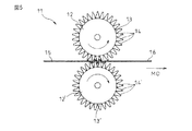
なお、ギア延伸は、図5に示されるようなギア延伸装置を用いて行うことができる。
図5は、ギア延伸を説明するための模式図である。図5に示されるギア延伸装置11は、一対のギアロール12及び12’を有する。ギアロール12及び12’の外周面13及び13’には、それぞれ、複数の歯14及び14’が配置されている。また、図5に示されるギア延伸装置11では、複数の歯14及び14’が、それぞれ、ギアロール12及び12’の回転軸線と平行に、それぞれ、外周面13及び13’に配置されている。複数の歯14及び14’をこのように配置することにより、高延伸部分及び低延伸部分を有する領域において、搬送方向MDとそれぞれ垂直な高延伸部分と低延伸部分とを、直交方向に交互に有する不織布を形成することができる。
The gear stretching can be performed using a gear stretching apparatus as shown in FIG.
FIG. 5 is a schematic diagram for explaining gear stretching. The
さらに、ギア延伸は、図6に示されるような、複数の歯が、ギアロールの外周面に、ギアロールの回転軸線に対して傾斜して配置されているギア延伸装置を用いて実施することができる。図6は、ギア延伸を説明するための模式図である。図6に示されるギア延伸装置11は、一対のギアロール12及び12’を有し、ギアロール12及び12’の外周面13及び13’には、それぞれ、複数の歯14及び14’が配置されている。また、図9に示すギア延伸装置11では、ギアロール12及び12’の回転軸線は、それぞれ、不織布の搬送方向MDと垂直である。さらに、複数の歯14及び14’は、それぞれ、回転軸線に対して一定の角度θを有するように、外周面13及び13’に配置されている。
Further, the gear stretching can be performed using a gear stretching device in which a plurality of teeth are arranged on the outer peripheral surface of the gear roll so as to be inclined with respect to the rotation axis of the gear roll as shown in FIG. . FIG. 6 is a schematic diagram for explaining gear stretching. The
なお、図6に示されるようなギア延伸装置では、θの角度及びギアピッチによっては、ギアロール12及び12’の外周面13及び13’に、それぞれ、1枚の歯14及び1枚の歯14’が配置されている場合もある。
上記ギア延伸装置は、形成される、凹凸を有する不織布の所望の性能に応じて、適宜選択することができる。
In the gear stretcher as shown in FIG. 6, depending on the angle θ and the gear pitch, one
The said gear extending | stretching apparatus can be suitably selected according to the desired performance of the nonwoven fabric which has an unevenness | corrugation formed.
上記ギア延伸装置において、ギアピッチは、約1〜約10mmが好ましく、そして約2〜約6mmがより好ましい。ギアピッチが約1mmを下回ると、ギアの刃を薄くする必要性が生じ、不織布が部分的に切断される場合があり、そしてギアピッチが約10mmを上回ると、延伸倍率が低く、繊維のウェブ化及び/又は繊維の塑性変形が不十分である場合がある。
ギアピッチは、図3において、符号19により表わされる、ある歯から次の歯の間の間隔を意味する。
In the gear stretching apparatus, the gear pitch is preferably about 1 to about 10 mm, and more preferably about 2 to about 6 mm. If the gear pitch is less than about 1 mm, the need to thin the gear blades may arise, and the nonwoven fabric may be partially cut, and if the gear pitch is greater than about 10 mm, the draw ratio is low, and the fiber web and In some cases, the plastic deformation of the fiber is insufficient.
The gear pitch means a distance between one tooth and the next tooth represented by
上記ギア延伸装置において、ギア噛込深さは、約0.5mm以上が好ましい。ギア噛込深さが約0.5mmを下回ると、不織布の延伸が不十分となり、高延伸部分が形成されにくくなる場合がある。
ギア噛込深さは、図3において、符号20により表わされる、上のギアロールの歯と、下のギアロールの歯とが重複する部分の深さを意味する。
In the gear stretching apparatus, the gear biting depth is preferably about 0.5 mm or more. If the gear biting depth is less than about 0.5 mm, the nonwoven fabric may not be sufficiently stretched, and a highly stretched portion may be difficult to form.
The gear biting depth means a depth of a portion where an upper gear roll tooth and a lower gear roll tooth overlap each other, which is represented by
高延伸部分と低延伸部分とを有する領域において、延伸させた方向の延伸倍率は、約30〜約400%であることが好ましく、そして約50〜約200%であることがより好ましい。延伸倍率が約30%を下回ると、処理すべき不織布が弾性変形するに留まり、処理すべき不織布に、高延伸部分及び低延伸部分を有する領域が実質的に形成されない場合があり、そして延伸倍率が約400%を上回ると、高延伸部分及び低延伸部分を有する領域の強度が弱く、伸長された繊維が脱落しやすくなり、搬送が困難になる場合がある。 In a region having a high stretch portion and a low stretch portion, the stretch ratio in the stretched direction is preferably about 30 to about 400%, and more preferably about 50 to about 200%. When the draw ratio is less than about 30%, the nonwoven fabric to be treated only remains elastically deformed, and there may be a case where a region having a high stretch portion and a low stretch portion is not substantially formed in the nonwoven fabric to be treated. If it exceeds about 400%, the strength of the region having the high-stretched portion and the low-stretched portion is weak, and the stretched fiber tends to fall off, which may make conveyance difficult.
本明細書において、「延伸倍率」は、ギアピッチをPとし、ギア噛込深さをDとした場合に、次の式:

本発明の方法は、上記高延伸部分及び低延伸部分を有する領域と、非延伸領域とを含む不織布を、支持体上に配置し、そして噴出された流体を、上記高延伸部分及び低延伸部分を有する領域と、上記非延伸領域との2つの領域に吹き付けるステップ(以下、「流体処理ステップ」と称する場合がある)を含む。 In the method of the present invention, a non-woven fabric including a region having the high-stretched portion and the low-stretched portion and a non-stretched region is disposed on a support, and the ejected fluid is placed in the high-stretched portion and the low-stretched portion. And a step of spraying the two regions of the non-stretched region and the non-stretched region (hereinafter sometimes referred to as “fluid treatment step”).
図7は、流体処理ステップに用いられる装置の例を示す図である。ここでは、図3に示されるギア延伸装置によりギア延伸された、高延伸部分及び低延伸部分を有する領域と、非延伸領域とを含む不織布を流体処理する例について説明する。
図3で形成された、高延伸部分及び低延伸部分を有する領域と、非延伸領域とを含む不織布16は、搬送方向MDの中心に存在する高延伸部分及び低延伸部分を有する領域17と、搬送方向MDの両側部に存在する非延伸領域18とを有する。図3で形成された、高延伸部分及び低延伸部分を有する領域と、非延伸領域とを含む不織布16を、パンチングプレートである支持体21に載せ、流体ノズル22から噴出される流体を、高延伸部分及び低延伸部分を有する領域17と、非延伸領域18との計3つの領域に吹き付けることができる。
FIG. 7 is a diagram illustrating an example of an apparatus used in the fluid treatment step. Here, an example will be described in which a nonwoven fabric including a region having a high stretch portion and a low stretch portion and a non-stretch region, which are gear stretched by the gear stretching apparatus shown in FIG.
The
なお、図7に示される装置では、流体ノズル22の下に、支持体21を間に挟んで、流体を受け入れるサクション部(図示せず)が設けられている。支持体21に載せられ、運ばれてきた、高延伸部分及び低延伸部分を有する領域と、非延伸領域とを含む不織布16に、流体ノズル22から噴出された流体が吹き付けられ、第1畝溝領域と、第2畝溝領域とを同一面に含む不織布1が形成される。なお、吹き付けられた流体は、サクション部(図示せず)から排出される。
In the apparatus shown in FIG. 7, a suction portion (not shown) for receiving fluid is provided below the
上記不均一延伸ステップで形成された、高延伸部分及び低延伸部分を有する領域において、高延伸部分に存在するウェブ状態の繊維及び/又は伸長された繊維の少なくとも一部が、流体が衝突する面(以下、流体衝突面と称する)では、噴出された流体が衝突し、次いで跳ね返ることに伴って、平面方向、例えば、直交方向に選り分けられる。また、流体衝突面と反対側の面(以下、非流体衝突面と称する)では、ウェブ状態の繊維及び/又は伸長された繊維の少なくとも一部が、高延伸部分及び低延伸部分を有する領域と、非延伸領域とを含む不織布を通過する流体の流れに沿って移動する。 In the region having the high-stretched portion and the low-stretched portion formed by the non-uniform stretch step, at least a part of the web-like fibers and / or the stretched fibers existing in the high-stretched portion is a surface on which the fluid collides. In (hereinafter referred to as a fluid collision surface), the ejected fluid collides and then rebounds, so that the fluid is selected in a plane direction, for example, an orthogonal direction. Further, in the surface opposite to the fluid collision surface (hereinafter referred to as a non-fluid collision surface), at least a part of the web-state fibers and / or the stretched fibers includes a region having a high stretch portion and a low stretch portion. And moves along the flow of fluid passing through the nonwoven fabric including the non-stretched region.
その結果、図1に示されるような、第1畝溝領域の複数の第1畝部と、複数の第1溝部とが形成される。流体ノズルの直下部分では、繊維が選り分けられるので、第1溝部が形成され、2つの流体ノズルの間の部分に、選り分けられた繊維が集まり、第1畝部を形成する。 As a result, as shown in FIG. 1, a plurality of first flange portions and a plurality of first groove portions in the first groove region are formed. Since the fibers are selected in the portion immediately below the fluid nozzle, the first groove portion is formed, and the selected fibers gather in the portion between the two fluid nozzles to form the first collar portion.
一方、非延伸領域では、不均一延伸ステップに付されていないため、ウェブ状態の繊維及び伸長された繊維が、原則的に存在しない。従って、移動することができる繊維の量が、高延伸部分及び低延伸部分を有する領域よりも少ないため、噴出された流体が衝突し、次いで跳ね返ることに伴って、多少の繊維が、平面方向、例えば、直交方向に選り分けられるが、その量は、高延伸部分及び低延伸部分を有する領域よりも少ない。 On the other hand, in the non-stretched region, since it has not been subjected to a non-uniform stretching step, there are essentially no web-like fibers and no stretched fibers. Thus, because the amount of fibers that can move is less than in regions with high stretch and low stretch, some of the fibers in the plane direction as the ejected fluid collides and then bounces For example, it is sorted in the orthogonal direction, but the amount is smaller than the region having the high stretch portion and the low stretch portion.
その結果、図1に示されるような、第2畝溝領域の複数の第2畝部と、複数の第2溝部とが形成されるが、第2畝部の高さは、第1畝部の高さよりも低くなる。なお、第2畝溝領域では、第1畝溝領域と同様に、流体ノズルの直下部分では、繊維が選り分けられるので、第2溝部が形成され、2つの流体ノズルの間の部分に、選り分けられた繊維が集まり、第2畝部を形成する。 As a result, as shown in FIG. 1, a plurality of second flange portions and a plurality of second groove portions in the second groove region are formed, and the height of the second flange portion is the first flange portion. It becomes lower than the height. In the second grooving region, as in the first grooving region, fibers are selected in the portion immediately below the fluid nozzle, so the second groove is formed and selected in the portion between the two fluid nozzles. The fibers gather to form a second collar.
なお、処理すべき不織布を、図3に記載されるようにギア延伸し、そして図7に示されるように流体処理した場合には、図1に示されるような、第1畝溝領域と、第2畝溝領域とを同一面に含む不織布が形成され、そして図1において、方向Aが、搬送方向MDに相当し、そして方向Bが、直交方向CDに相当する。 In addition, when the nonwoven fabric to be processed is gear-stretched as shown in FIG. 3 and fluid-treated as shown in FIG. 7, the first grooving region as shown in FIG. A non-woven fabric including the second ridge groove region is formed on the same surface, and in FIG. 1, the direction A corresponds to the transport direction MD, and the direction B corresponds to the orthogonal direction CD.
本発明の、第1畝溝領域と、第2畝溝領域とを同一面に含む不織布では、第1畝溝領域における繊維の径が、第2畝溝領域における繊維の径よりも細い。本発明の不織布の用途等によって、その度合いは異なるが、例えば、第1畝溝領域における繊維の径は、第2畝溝領域における繊維の径の、約3%以上細いことが好ましく、約5%以上細いことがより好ましく、そして約7%以上細いことがさらに好ましい。第1畝溝領域における繊維の径を細く、長くすることにより、第1畝溝領域における畝の高さを高くすることにつながるからである。また、第1畝溝領域における繊維の径が、余り細くなると、強度に問題が生じうるので、第1畝溝領域における繊維の径は、第2畝溝領域における繊維の径の約50%が下限であろう。 In the nonwoven fabric of the present invention including the first ridge groove region and the second ridge groove region on the same surface, the fiber diameter in the first ridge groove region is smaller than the fiber diameter in the second ridge groove region. For example, the fiber diameter in the first groove region is preferably about 3% or more smaller than the fiber diameter in the second groove region, and is about 5%. % Or more is more preferable, and about 7% or more is still more preferable. This is because by reducing the length of the fiber in the first grooving region, the height of the ridge in the first grooving region is increased. In addition, if the fiber diameter in the first grooving region is too thin, there may be a problem in strength. Therefore, the fiber diameter in the first grooving region is about 50% of the fiber diameter in the second grooving region. It will be the lower limit.
本発明の、第1畝溝領域と、第2畝溝領域とを同一面に含む不織布では、第1畝部の畝の高さは、第2畝部の畝の高さよりも、約1.1倍以上高いことが好ましく、約1.2倍以上高いことがより好ましく、そして約1.3倍以上高いことがさらに好ましい。第1畝部の畝の高さは、第2畝部の畝の高さよりも、約1.1倍以上高くないと、第1畝溝領域と、第2畝溝領域との性質の差が出にくい傾向がある。また、単一の不織布から、第1畝溝領域と、第2畝溝領域とを同一面に含む不織布を形成するため、第1畝部の畝の高さは、第2畝部の畝の高さよりも、10倍程度高いものが、上限となるであろう。 In the nonwoven fabric of the present invention including the first ridge groove region and the second ridge groove region on the same surface, the height of the ridges of the first ridge portion is about 1. It is preferably 1 or more times higher, more preferably about 1.2 or more times higher, and more preferably about 1.3 or more times higher. If the height of the ridge of the first ridge portion is not higher than the height of the ridge of the second ridge portion by about 1.1 times or more, the difference in properties between the first ridge region and the second ridge region is There is a tendency to be hard to come out. Moreover, in order to form the nonwoven fabric which contains a 1st ridge groove area | region and a 2nd ridge groove area | region on the same surface from a single nonwoven fabric, the height of the ridge of a 1st ridge part is the height of the ridge of a 2nd ridge part. The upper limit would be about 10 times higher than the height.
本発明の、第1畝溝領域と、第2畝溝領域とを同一面に含む不織布において、第1畝溝領域の畝の高さは、当該不織布が、吸収性物品に用いられる場合には、例えば、約0.1〜約5mmであることが好ましく、約0.3〜約4mmであることがより好ましく、そして約0.5〜約3mmであることがさらに好ましい。上記高さが約0.1mmを下回ると、第1畝溝領域及び第2畝溝領域の差が小さく、それらの領域の性質、特に、液透過性及び液引込性の差が出にくい傾向があり、そして約5mmを上回ると、吸収性物品として使用した場合、全体として厚みが増加し、装着感が悪くなる、かさばって携帯しにくくなる場合がある。 In the nonwoven fabric of the present invention including the first ridge groove region and the second ridge groove region on the same surface, the height of the ridges in the first ridge groove region is determined when the nonwoven fabric is used for an absorbent article. For example, it is preferably about 0.1 to about 5 mm, more preferably about 0.3 to about 4 mm, and even more preferably about 0.5 to about 3 mm. When the height is less than about 0.1 mm, the difference between the first and second groove regions is small, and the characteristics of these regions, in particular, the difference in liquid permeability and liquid drawability tends not to occur. If it exceeds about 5 mm, when used as an absorbent article, the thickness increases as a whole, the feeling of wearing becomes worse, and it may be bulky and difficult to carry.
本発明の、第1畝溝領域と、第2畝溝領域とを同一面に含む不織布において、第1畝溝領域の第1畝部及び第1溝部、並びに第2畝溝領域の第2畝部及び第2溝部の幅は、当該不織布が、吸収性物品に用いられる場合には、例えば、約0.2〜約10mmであることが好ましく、そして約0.5〜約5mmであることがより好ましい。上記幅が約0.2mmを下回ると、不織布に畝溝構造が形成されにくくなる傾向があり、そして約10mmを上回ると、肌と本発明の不織布との接触面積が大きくなるため、蒸れやすくなる、溝の幅が大きくなることで畝部がつぶれやすくなる傾向がある。 In the nonwoven fabric of the present invention including the first ridge groove region and the second ridge groove region on the same surface, the first ridge portion and the first groove portion of the first ridge groove region, and the second ridge of the second ridge groove region. When the nonwoven fabric is used for an absorbent article, the width of the portion and the second groove is preferably, for example, about 0.2 to about 10 mm, and about 0.5 to about 5 mm. More preferred. When the width is less than about 0.2 mm, the groove structure tends to be difficult to be formed in the nonwoven fabric, and when the width is more than about 10 mm, the contact area between the skin and the nonwoven fabric of the present invention is increased, so that it is easily stuffy. In addition, since the width of the groove is increased, the heel portion tends to be crushed.
なお、第1畝溝領域において、第1畝部及び第1溝部の幅が同一である、第1畝部の幅が第1溝部の幅よりも大きい、又は第1畝部の幅が第1溝部の幅よりも小さくすることができるが、第1畝部の幅が大きくなる場合には、第1溝部の幅を、第1畝部の幅よりも小さくする方が好ましい。 In the first ridge region, the width of the first ridge and the first groove is the same, the width of the first ridge is larger than the width of the first groove, or the width of the first ridge is first. Although it can be made smaller than the width of the groove portion, when the width of the first flange portion is increased, it is preferable to make the width of the first groove portion smaller than the width of the first flange portion.
上記流体処理ステップにおいて用いられる流体としては、空気、例えば、加熱された空気、水蒸気、又は水、例えば、熱水が挙げられる。
上記流体を、高延伸部分及び低延伸部分を有する領域と、非延伸領域とを含む不織布に、固定された流体ノズルから吹き付けることができ、又は直交方向CDに往復する流体ノズルから吹き付けることができる。直交方向CDに往復する流体ノズルから、高延伸部分及び低延伸部分を有する領域と、非延伸領域とを含む不織布に流体を吹き付けた場合には、波形の第1畝部及び第1溝部が形成される。
Examples of the fluid used in the fluid treatment step include air, for example, heated air, water vapor, or water, for example, hot water.
The fluid can be sprayed from a fixed fluid nozzle to a nonwoven fabric including a region having a high stretch portion and a low stretch portion and a non-stretch region, or from a fluid nozzle that reciprocates in the orthogonal direction CD. . When fluid is sprayed from a fluid nozzle that reciprocates in the orthogonal direction CD onto a non-woven fabric including a region having a high stretch portion and a low stretch portion and a non-stretch region, a corrugated first ridge portion and a first groove portion are formed. Is done.
また、上記流体を、高延伸部分及び低延伸部分を有する領域と、非延伸領域とを含む不織布に、連続的、又は断続的に流体ノズルから吹き付けることができる。また、これらを組み合わせることもできる。なお、上記流体ノズルから流体を、高延伸部分及び低延伸部分を有する領域と、非延伸領域とを含む不織布に、断続的に吹き付けた場合には、断続的な第1畝部、第1溝部、第2畝部、及び第2溝部が形成される。 Moreover, the fluid can be sprayed from a fluid nozzle continuously or intermittently onto a nonwoven fabric including a region having a high stretch portion and a low stretch portion and a non-stretch region. Moreover, these can also be combined. In addition, when the fluid is intermittently sprayed from the fluid nozzle onto the nonwoven fabric including the region having the high stretch portion and the low stretch portion and the non-stretch region, the intermittent first first flange portion and the first groove portion. The second flange portion and the second groove portion are formed.
上記流体は、高延伸部分及び低延伸部分を有する領域と、非延伸領域とを含む不織布、特に、非延伸領域の状態によって、適宜選択することができる。例えば、高延伸部分及び低延伸部分を有する領域において、ギアピッチが小さく、延伸倍率が大きい場合、非延伸領域において、繊維同士の接合部の量が少ない場合等は、比較的低いエネルギーで繊維を移動させることができるため、流体として空気又は水蒸気を選択することが好ましい。また、高延伸部分及び低延伸部分を有する領域において、ギアピッチが大きく、延伸倍率が低い場合、非延伸領域において、繊維同士の接合部の量が多い場合等は、繊維を移動させるために比較的高いエネルギーが必要であるため、流体として水又は水蒸気を選択することが好ましく、そして水蒸気がより好ましい。というのは、繊維量が多い部分に水分が残存しにくく、そして移動すべき部分の、伸長された繊維を簡易に移動させることができるからである。 The fluid can be appropriately selected according to a nonwoven fabric including a region having a high stretch portion and a low stretch portion and a non-stretch region, particularly a state of the non-stretch region. For example, if the gear pitch is small and the draw ratio is large in a region having a high stretch portion and a low stretch portion, or if the amount of joints between fibers is small in a non-stretch region, the fibers are moved with relatively low energy. Therefore, it is preferable to select air or water vapor as the fluid. Further, in a region having a high stretch portion and a low stretch portion, when the gear pitch is large and the stretch ratio is low, in the non-stretch region, when the amount of the joint portion between the fibers is large, it is relatively easy to move the fibers. Because high energy is required, it is preferred to select water or steam as the fluid, and steam is more preferred. This is because moisture hardly remains in a portion where the amount of fiber is large, and the stretched fiber in the portion to be moved can be easily moved.
上記流体処理ステップは、当技術分野で公知の装置を用い、そして公知の方法で行うことができる。
本発明の実施形態の1つでは、高延伸部分及び低延伸部分を有する領域と、非延伸領域とを含む不織布を支持するために用いられる支持体は、当技術分野で通常用いられている支持体、例えば、金属、例えば、パンチングプレート、プラスチック製のコンベアネット、抄紙網等であることができる。上記支持体は、流体透過性を有するのが一般的である。
上記パンチングプレートとしては、例えば、丸穴型、例えば、丸穴60°千鳥型、丸穴角千鳥及び丸穴直列型、角穴型、丸十型、雲型、雲千鳥型等のパンチングプレートが挙げられる。
The fluid treatment step can be performed using a known device in the art and by a known method.
In one embodiment of the present invention, the support used to support the nonwoven comprising a region having a high stretch portion and a low stretch portion and a non-stretch region is a support commonly used in the art. The body can be a metal, for example, a punching plate, a plastic conveyor net, a papermaking net, and the like. The support is generally fluid permeable.
Examples of the punching plate include a round hole type, for example, a round hole 60 ° zigzag type, a round hole square zigzag and round hole series type, a square hole type, a round dove type, a cloud type, and a cloud zigzag type. Can be mentioned.
なお、非流体衝突面では、繊維の一部が、流体の流れに沿って移動するので、特に、高延伸部分及び低延伸部分を有する領域において、流体を吹き付ける面と反対側の面に、あらかじめ定められた形状及び配列の突状部及び窪み部を有する支持体が配置された場合には、第1畝溝領域と、第2畝溝領域とを有する面と反対側の面に、凹凸を形成することもできる。 In the non-fluid collision surface, a part of the fiber moves along the flow of the fluid. Therefore, particularly in the region having the high-stretched portion and the low-stretched portion, the surface on the side opposite to the surface to which the fluid is sprayed in advance. When the support having the projecting portions and the recessed portions having the defined shape and arrangement is disposed, the surface opposite to the surface having the first groove region and the second groove region is uneven. It can also be formed.
上記突状部及び窪み部を有する支持体としては、例えば、(i)搬送方向にそれぞれ平行な突状部及び窪み部であって、直交方向に交互に配置されている突状部及び窪み部を有する支持体、(ii)搬送方向に対して傾斜を有する突状部及び窪み部であって、当該傾斜の方向と直交する方向に交互に配置されている突状部及び窪み部を有する支持体、(iii)あらかじめ定められた形状(例えば、立方体形状、円柱形状、半球形状等)の突状部及び/又は窪み部が、あらかじめ定められた配列(例えば、ハート型、星型等の配列)で配置されている突状部及び窪み部を有する支持体等が挙げられる。 Examples of the support having the protrusions and the depressions include (i) protrusions and depressions that are parallel to the conveying direction, and are alternately arranged in the orthogonal direction. (Ii) Projections and depressions having an inclination with respect to the conveying direction, and having projections and depressions alternately arranged in a direction perpendicular to the direction of the inclination A body, (iii) a projecting portion and / or a hollow portion having a predetermined shape (for example, a cubic shape, a columnar shape, a hemispherical shape, etc.), and a predetermined array (for example, a heart shape, a star shape, etc.) ) And the like having a projecting portion and a recessed portion arranged in the above.
また、流体を吹き付ける条件は、処理すべき不織布の種類、形成すべき、第1畝溝領域と、第2畝溝領域とを同一面に含む不織布の用途等によっても異なるが、例えば、流体が水蒸気の場合には、噴出圧力:約0.2〜約0.8MPa、水蒸気温度:約119〜約167℃、ノズル及び支持体間間隔:約0.1〜約10mmであることができる。また、流体が熱水である場合には、噴出圧力:約1〜約10MPa、熱水温度:約50〜約100℃、ノズル及び支持体間間隔:約0.1〜約30mmであることができる。なお、ノズル同士の間隔は、所望の、第1畝溝領域の第1畝部及び第1溝部、並びに第2畝溝領域の第2畝部及び第2溝部の幅によって決まる。 In addition, the conditions for spraying the fluid vary depending on the type of nonwoven fabric to be treated, the use of the nonwoven fabric including the first ridge groove region and the second ridge groove region to be formed, etc. In the case of water vapor, the ejection pressure can be about 0.2 to about 0.8 MPa, the water vapor temperature can be about 119 to about 167 ° C., and the distance between the nozzle and the support can be about 0.1 to about 10 mm. When the fluid is hot water, the ejection pressure is about 1 to about 10 MPa, the hot water temperature is about 50 to about 100 ° C., and the distance between the nozzle and the support is about 0.1 to about 30 mm. it can. The spacing between the nozzles is determined by the desired widths of the first and first groove portions of the first groove region and the second and second groove portions of the second groove region.
本発明の、第1畝溝領域と、第2畝溝領域とを同一面に含む不織布は、その構造に由来して、第1畝溝領域が、第2畝溝領域よりも透液性に優れ、第2畝溝領域が、第1畝溝領域よりも液引込性に優れる傾向がある。具体的には、第1畝溝領域は、ギア延伸ステップ及び流体処理ステップに由来して、特に、第1畝部において繊維が厚み方向に配向し、繊維間距離が第2畝溝領域よりも大きく、低密度であり、液が透過しやすいため、第2畝溝領域よりも透液性に優れる傾向がある。
一方、第2畝溝領域は、ギア延伸ステップを経ずに、流体処理ステップを受けており、繊維間距離が第1畝溝領域よりも小さく、高密度の構造を有し、毛細管力が働きやすいので、液を引き込み、そして拡散しやすい。従って、第2畝溝領域は、第1畝溝領域よりも液引込性に優れる傾向がある。
The non-woven fabric of the present invention including the first ridge groove region and the second ridge groove region on the same surface is derived from the structure, and the first ridge groove region is more permeable than the second ridge groove region. The second grooving region tends to be superior in liquid drawability than the first grooving region. Specifically, the first ridge groove region originates from the gear stretching step and the fluid treatment step, and in particular, the fibers are oriented in the thickness direction in the first ridge portion, and the inter-fiber distance is greater than that of the second ridge groove region. Since it is large and has a low density and easily penetrates the liquid, the liquid permeability tends to be better than that of the second groove region.
On the other hand, the second grooving region has undergone a fluid treatment step without going through a gear stretching step, and the interfiber distance is smaller than that of the first grooving region, has a high-density structure, and capillary force works. It is easy to draw in and diffuse. Therefore, the second grooving region tends to be more excellent in liquid drawing than the first grooving region.
本発明の、第1畝溝領域と、第2畝溝領域とを同一面に含む不織布は、吸収性物品、例えば、生理用品及び使い捨ておむつ、清掃用品、例えば、ワイパー、並びに医療用品、例えば、マスク等に有用である。上記吸収性物品としては、液透過性のトップシートと、液不透過性のバックシートと、上記トップシート及びバックシートの間の吸収体とを含むものが挙げられる。本発明の、第1畝溝領域と、第2畝溝領域とを同一面に含む不織布を、上記液透過性のトップシートに採用する場合には、第1畝溝領域が、吸収性物品の長手方向中心部に存在し、第2畝溝領域が、長手方向の両側部に存在することが好ましい。第1畝溝領域は透液性が高い傾向があり、吸収した液体を迅速に吸収体に移行させることができ、そして第2畝溝領域は、クレム吸水度等により評価されるように液引込性に優れる傾向があり、長手方向中心部で吸収した液体を引込み、拡散させ、吸収体全体を有効に使用することができるからである。 The non-woven fabric of the present invention comprising the first ridge groove region and the second ridge groove region on the same surface is an absorbent article such as a sanitary article and disposable diaper, a cleaning article such as a wiper, and a medical article such as Useful for masks and the like. Examples of the absorbent article include a liquid permeable top sheet, a liquid impermeable back sheet, and an absorbent body between the top sheet and the back sheet. When the nonwoven fabric including the first ridge groove region and the second ridge groove region of the present invention on the same surface is used for the liquid-permeable top sheet, the first ridge groove region is the absorbent article. It exists in the longitudinal center part, and it is preferable that a 2nd groove area exists in the both sides of a longitudinal direction. The first grooving region tends to have high liquid permeability, the absorbed liquid can be quickly transferred to the absorbent body, and the second grooving region draws in the liquid as evaluated by the Krem water absorbency etc. This is because the liquid absorbed at the central portion in the longitudinal direction is drawn and diffused, and the entire absorber can be used effectively.
以下、実施例及び比較例を挙げて本発明を説明するが、本発明はこれらの実施例に限定されるものではない。
実施例及び比較例において評価された項目の、測定条件は、以下の通りである。
[繊維径]
繊維径は、(株)キーエンス製 リアルサーフェスビュー顕微鏡VE−7800を用いて、加速電圧5kV、300倍にて観察した試料において、任意の繊維50本をピックアップし、その繊維径を測定し、それらの相加平均を繊維径として採用する。
[畝の高さ]
畝の高さは、キーエンス株式会社製高精度2次元レーザー変位計を用いて、畝の最も高い点を任意に10ヶ所測定し、その相加平均を採用する。
EXAMPLES Hereinafter, although an Example and a comparative example are given and this invention is demonstrated, this invention is not limited to these Examples.
The measurement conditions of the items evaluated in the examples and comparative examples are as follows.
[Fiber diameter]
The fiber diameter was picked up from 50 arbitrary fibers in a sample observed at 300x with an acceleration voltage of 5 kV using a real surface view microscope VE-7800 manufactured by Keyence Corporation, and the fiber diameter was measured. Is used as the fiber diameter.
[Head height]
The height of the heel is determined by arbitrarily measuring 10 highest points of the heel using a high-precision two-dimensional laser displacement meter manufactured by Keyence Corporation, and adopting an arithmetic average thereof.
[坪量]
坪量は、JIS L 1906の5.2に従って測定する。
[嵩]
嵩は、(株)大栄科学精器製作所製 THICKNESS GAUGE UF−60を用いて測定する。
[Basis weight]
The basis weight is measured according to 5.2 of JIS L 1906.
[Bulk]
The bulk is measured using THICKNESS GAUGE UF-60 manufactured by Daiei Kagaku Seiki Seisakusho.
[圧縮特性]
カトーテック株式会社製、自動化圧縮試験器、KES−FB3を用いて、圧縮特性を評価する。
測定条件は、以下の通りである。
SENS :2
速度 :0.02mm/秒
ストローク:5mm/10V
加圧面積 :2cm2
取込み間隔:0.1秒
上限荷重 :50g/cm2
繰返し回数:1回
[Compression characteristics]
The compression characteristics are evaluated using an automated compression tester, KES-FB3, manufactured by Kato Tech Co., Ltd.
The measurement conditions are as follows.
SENS: 2
Speed: 0.02mm / sec Stroke: 5mm / 10V
Pressurized area: 2 cm 2
Uptake interval: 0.1 seconds Upper limit load: 50 g / cm 2
Repeat count: 1 time
圧縮特性は、不織布1cm2当りの圧縮エネルギーを意味するWCと、圧力0.5gf/cm2における試料の厚みを意味するT0と、圧力50gf/cm2における試料の厚みを意味するTmとにより評価する。WCは、値が大きいほど圧縮されやすいことを意味する。
Compression properties, and WC, which means compression energy per
[通気度]
通気度は、カトーテック株式会社のKES−F8−AP1通気性試験器を用いて測定し、単位を「m3/m2/分」に換算する。
不織布の厚さ方向の通気度は、100mm×100mmの大きさにカットした不織布を、通気性試験器にセットして測定する。
不織布の平面方向の通気度は、100mm×100mmの大きさにカットした不織布を、通気性試験器にセットし、100mm×100mmの大きさのアクリル板をその上にさらにセットし、3.5mN/cm2の加重下で測定する。
[クレム吸水度]
JIS P 8141に準拠し、5分間の吸上げ高さ(mm)として評価した。
[Air permeability]
The air permeability is measured using a KES-F8-AP1 air permeability tester manufactured by Kato Tech Co., Ltd., and the unit is converted to “m 3 / m 2 / min”.
The air permeability in the thickness direction of the nonwoven fabric is measured by setting a nonwoven fabric cut to a size of 100 mm × 100 mm in a breathability tester.
For the air permeability in the plane direction of the nonwoven fabric, a nonwoven fabric cut to a size of 100 mm × 100 mm is set in a breathability tester, and an acrylic plate having a size of 100 mm × 100 mm is further set on the nonwoven fabric. Measure under a weight of cm 2 .
[Clem water absorption]
In accordance with JIS P 8141, the suction height (mm) for 5 minutes was evaluated.
[透液性]
透液性を、LENZING社製、LISTERストライクスルー試験器を用いて評価する。評価手順は、以下の通りである。
(1)100×100mmの大きさにカットしたろ紙(ADVANTEC FILTER PAPER GRADE 2)5枚の上に、100×100mmの大きさにカットした試料を配置し、その上に通電透液プレートを配置する。
(2)ストライクスルー試験機本体に、ろ紙、試料及び通電透液プレートをセットする。なお、試料は、試験機の開口部と、第1畝溝領域又は第2畝溝領域が一致するようにセットする。
(3)ストライクスルー試験機本体に、生理食塩水5mLを入れる。
(4)ストライクスルー試験機本体から、上記生理食塩水(室温)を、通電透液プレートの開孔部に落下させる。
(5)通電透液プレートの通電時間を記録する。
(6)測定を2回繰返し、計3回の平均値を、透液時間とする。
なお、試料をセットしない場合、すなわち、ろ紙5枚における透液時間は、69秒であった。
[Liquid permeability]
The liquid permeability is evaluated using a LISTER strike-through tester manufactured by LENZING. The evaluation procedure is as follows.
(1) A sample cut to a size of 100 × 100 mm is placed on five pieces of filter paper (ADVANTEC FILTER PAPER GRADE 2) cut to a size of 100 × 100 mm, and an electrically permeable liquid plate is placed thereon. .
(2) Set a filter paper, a sample and a current-permeable plate on the strike-through tester body. Note that the sample is set so that the opening of the testing machine and the first or second groove region coincide with each other.
(3)
(4) The physiological saline (room temperature) is dropped from the strike-through tester main body into the opening of the conductive liquid-permeable plate.
(5) Record the energization time of the energized permeable plate.
(6) The measurement is repeated twice, and the average value of the total three times is defined as the liquid permeation time.
In the case where the sample was not set, that is, the liquid permeation time in 5 sheets of filter paper was 69 seconds.
[製造例1]
−ギア延伸−
処理すべき不織布として、エアスルー不織布を準備し、図3に示すようなギア延伸装置(ギア温度:55℃,ギアピッチ:2.5mm,ギア噛込深さ:3.0mm,ギア先端幅:0.2mm,処理速度:50m/分)を用いて、図3に示されるように、高延伸部分及び低延伸部分を有する領域と、非延伸領域とを含む不織布を形成した。上記高延伸部分及び低延伸部分を有する領域は、図3に示されるように、搬送方向の中心に存在し、そして非延伸領域は、搬送方向の両側部に存在した。高延伸部分及び低延伸部分を有する領域は、搬送方向に平行な高延伸部分と低延伸部分とを、搬送方向と直交する直交方向に交互に有していた。上記高延伸部分及び低延伸部分を有する領域の、直交方向の延伸倍率は、160%であった。
[Production Example 1]
-Gear extension-
As a nonwoven fabric to be treated, an air-through nonwoven fabric was prepared, and a gear stretching apparatus (gear temperature: 55 ° C., gear pitch: 2.5 mm, gear biting depth: 3.0 mm, gear tip width: 0. 0) as shown in FIG. 2 mm, a non-woven fabric including a region having a high stretch portion and a low stretch portion and a non-stretch region was formed as shown in FIG. 3. The area | region which has the said high extending | stretching part and the low extending | stretching part exists in the center of a conveyance direction, and the non-stretching area | region existed in the both sides of the conveyance direction, as FIG. 3 shows. The area | region which has a high extending | stretching part and a low extending | stretching part had alternately the high extending | stretching part and low extending | stretching part parallel to a conveyance direction in the orthogonal direction orthogonal to a conveyance direction. The stretch ratio in the orthogonal direction of the region having the high stretch portion and the low stretch portion was 160%.
ギア延伸されたエアスルー不織布において、歯の先端部に接していた低延伸部分では、融着部分が残存していた。また、歯の先端部に接していなかった高延伸部分では、融着部分が一部破壊され、ウェブ領域が形成されていた。
上記エアスルー不織布、高延伸部分及び低延伸部分を有する領域、及び非延伸領域の特性を、表1に示す。
In the air-through nonwoven fabric subjected to gear stretching, the fused portion remained in the low-stretched portion that was in contact with the tip of the tooth. Further, in the highly stretched portion that was not in contact with the tip portion of the tooth, the fused portion was partially broken and a web region was formed.
Table 1 shows the characteristics of the air-through nonwoven fabric, the region having the high stretch portion and the low stretch portion, and the non-stretch region.
−水蒸気処理−
上記高延伸部分及び低延伸部分を有する領域と、非延伸領域とを含む不織布を、丸穴60°千鳥型のパンチングプレート(φ:1.0mm、MDピッチ:2.60mm、CDピッチ:1.5mm、厚さ:1.0mm)からなる支持体に載せた。次いで、上記高延伸部分及び低延伸部分を有する領域と、非延伸領域とを含む不織布を、3.0mmの間隔で、複数のノズル(φ:0.5mm)を備える水蒸気処理システム(噴出圧力:0.4Mpa,水蒸気温度:約141℃)に、ノズル及び支持体間距離を4.0mmに保ちながら、50m/分の速度で通し、不織布1を得た。
不織布1の特性値を表1に示す。
-Steam treatment-
A non-woven fabric including a region having the high stretch portion and the low stretch portion and a non-stretch region is formed into a round hole 60 ° staggered punching plate (φ: 1.0 mm, MD pitch: 2.60 mm, CD pitch: 1. 5 mm, thickness: 1.0 mm). Next, a steam treatment system (jet pressure: jetting pressure: a nonwoven fabric including a region having the high stretch portion and the low stretch portion and a non-stretch region having a plurality of nozzles (φ: 0.5 mm) at an interval of 3.0 mm. The
The characteristic values of the
なお、通気度に関しては、本発明の不織布が、吸収性物品のトップシートとして用いられた場合に、トップシート全体の通気度を把握したいため、第1畝溝領域と、第2畝溝領域とを、面積比で1:1となるように含む場所の通気度を測定した。また、比較のため、高延伸部分及び低延伸部分を有する領域と、非延伸領域とを含む不織布に関しても、高延伸部分及び低延伸部分を有する領域と、非延伸領域とを、面積比で1:1となるように含む場所の通気度を測定した。 Regarding the air permeability, when the nonwoven fabric of the present invention is used as a top sheet of an absorbent article, in order to grasp the air permeability of the entire top sheet, the first ridge groove area, the second ridge groove area, Was measured for the air permeability of the place including the area ratio of 1: 1. In addition, for comparison, regarding a nonwoven fabric including a region having a high stretch portion and a low stretch portion and a non-stretch region, the area having a high stretch portion and a low stretch portion and the non-stretch region are 1 in area ratio. : The air permeability of the place where it was included was measured.
[製造例2]
上記エアスルー不織布を、スパンボンド不織布に変更し、ギア延伸の際の処理速度を30m/分に変更し、そして水蒸気処理において、噴出圧力を0.35Mpa,水蒸気温度:約136℃に変更した以外は、製造例1に従って、不織布2を得た。
上記スパンボンド不織布、高延伸部分及び低延伸部分を有する領域、及び非延伸領域、並びに不織布2の特性を表1に示す。
なお、通気度に関しては、製造例1と同様である。
[Production Example 2]
The air-through nonwoven fabric is changed to a spunbond nonwoven fabric, the processing speed at the time of gear stretching is changed to 30 m / min, and the steam pressure is changed to 0.35 Mpa, steam temperature: about 136 ° C. According to Production Example 1, a
Table 1 shows the properties of the spunbonded nonwoven fabric, the region having the high stretched portion and the low stretched portion, the non-stretched region, and the
The air permeability is the same as in Production Example 1.
表1から、不織布の種類を問わず、第1畝溝領域は、第2畝溝領域よりも透液性が高く、そして第2畝溝領域は、第1畝溝領域よりもクレム吸水度が高いことが分かる。
従って、本発明の、第1畝溝領域と、第2畝溝領域とを同一面に含む不織布は、上記液透過性のトップシートに好適であることが示唆される。例えば、液透過性のトップシートにおいて、第1畝溝領域を、吸収性物品の長手方向中心部に配置し且つ第2畝溝領域が長手方向の両側部に存在するように配置すると、長手方向中心部は吸液性に優れ、そして長手方向両側部は液体の引込性、拡散性に優れることとなるからである。
From Table 1, regardless of the type of nonwoven fabric, the first ridge groove region is higher in liquid permeability than the second ridge groove region, and the second ridge groove region has a Klemm water absorption rate than the first ridge groove region. I understand that it is expensive.
Therefore, it is suggested that the nonwoven fabric of the present invention including the first ridge groove region and the second ridge groove region on the same surface is suitable for the liquid-permeable top sheet. For example, in a liquid-permeable top sheet, when the first ridge groove region is disposed at the center in the longitudinal direction of the absorbent article and the second ridge groove region is present on both sides in the longitudinal direction, the longitudinal direction This is because the central portion is excellent in liquid absorbency, and both side portions in the longitudinal direction are excellent in liquid drawability and diffusibility.
1 第1畝溝領域と、第2畝溝領域とを同一面に含む不織布
2 第1畝溝領域
3 第2畝溝領域
4 第1畝部
5 第1溝部
6 第2畝部
7 第2溝部
11 ギア延伸装置
12,12’ ギアロール
13,13’ 外周面
14,14’ 複数の歯
15 処理すべき不織布
16 高延伸部分及び低延伸部分を有する領域と、非延伸領域とを含む不織布
17 高延伸部分及び低延伸部分を有する領域
17’ 高延伸部分
17’’ 低延伸部分
18 非延伸領域
19 ギアピッチ
20 ギア噛込深さ
21 支持体
22 流体ノズル
MD 搬送方向
CD 直交方向
DESCRIPTION OF
Claims (13)
第1畝溝領域が、複数の第1畝部と、複数の第1溝部とを含み、
第2畝溝領域が、複数の第2畝部と、複数の第2溝部とを含み、
第1畝部の畝の高さが、第2畝部の畝の高さより高く、
第1畝溝領域における繊維の径が、第2畝溝領域における繊維の径よりも細い、
ことを特徴とする、前記不織布。 A non-woven fabric comprising a first ridge groove region and a second ridge groove region on the same surface,
The first groove region includes a plurality of first groove portions and a plurality of first groove portions,
The second groove region includes a plurality of second groove portions and a plurality of second groove portions,
The height of the first collar is higher than the height of the second collar,
The fiber diameter in the first grooving region is thinner than the fiber diameter in the second grooving region,
The said nonwoven fabric characterized by the above-mentioned.
前記トップシートが、請求項1〜7のいずれか一項に記載の不織布から形成されている、
前記吸収性物品。 An absorbent article comprising a liquid-permeable top sheet, a liquid-impermeable back sheet, and an absorbent body between the top sheet and the back sheet,
The top sheet is formed from the nonwoven fabric according to any one of claims 1 to 7,
The absorbent article.
処理すべき不織布を準備するステップ、
前記処理すべき不織布の一部を、高延伸部分及び低延伸部分を有する領域が形成されるように不均一に延伸し、高延伸部分及び低延伸部分を有する領域と、非延伸領域とを含む不織布を形成するステップ、そして
前記高延伸部分及び低延伸部分を有する領域と、非延伸領域とを含む不織布を、支持体上に配置し、そして噴出された流体を、前記高延伸部分及び低延伸部分を有する領域と、前記非延伸領域との2つの領域に吹き付けるステップ、
を含む方法。 A method for producing the nonwoven fabric according to any one of claims 1 to 7,
Preparing a nonwoven to be treated;
A part of the nonwoven fabric to be treated is stretched non-uniformly so as to form a region having a high stretch portion and a low stretch portion, and includes a region having a high stretch portion and a low stretch portion, and a non-stretch region. Forming a non-woven fabric, and placing a non-woven fabric comprising a region having the high-stretched portion and the low-stretched portion and a non-stretched region on a support, and ejecting the fluid into the high-stretched portion and the low-stretched portion. Spraying two regions, a region having a portion and the non-stretched region,
Including methods.
Priority Applications (3)
| Application Number | Priority Date | Filing Date | Title |
|---|---|---|---|
| JP2011082230A JP5642009B2 (en) | 2011-04-01 | 2011-04-01 | Nonwoven fabric, absorbent article containing the nonwoven fabric, and method for producing the nonwoven fabric |
| PCT/JP2012/054299 WO2012137553A1 (en) | 2011-04-01 | 2012-02-22 | Nonwoven fabric, absorbent article including nonwoven fabric, and method for manufacturing nonwoven fabric |
| TW101109498A TWI565846B (en) | 2011-04-01 | 2012-03-20 | A nonwoven fabric, an absorbent article containing the nonwoven fabric, and a method of manufacturing the nonwoven fabric |
Applications Claiming Priority (1)
| Application Number | Priority Date | Filing Date | Title |
|---|---|---|---|
| JP2011082230A JP5642009B2 (en) | 2011-04-01 | 2011-04-01 | Nonwoven fabric, absorbent article containing the nonwoven fabric, and method for producing the nonwoven fabric |
Publications (2)
| Publication Number | Publication Date |
|---|---|
| JP2012214938A JP2012214938A (en) | 2012-11-08 |
| JP5642009B2 true JP5642009B2 (en) | 2014-12-17 |
Family
ID=46968957
Family Applications (1)
| Application Number | Title | Priority Date | Filing Date |
|---|---|---|---|
| JP2011082230A Active JP5642009B2 (en) | 2011-04-01 | 2011-04-01 | Nonwoven fabric, absorbent article containing the nonwoven fabric, and method for producing the nonwoven fabric |
Country Status (3)
| Country | Link |
|---|---|
| JP (1) | JP5642009B2 (en) |
| TW (1) | TWI565846B (en) |
| WO (1) | WO2012137553A1 (en) |
Families Citing this family (17)
| Publication number | Priority date | Publication date | Assignee | Title |
|---|---|---|---|---|
| US9533067B2 (en) | 2013-05-03 | 2017-01-03 | The Procter & Gamble Company | Absorbent articles comprising stretch laminates |
| JP2015027348A (en) * | 2013-07-30 | 2015-02-12 | 花王株式会社 | Absorbent article |
| JP6419454B2 (en) * | 2013-07-30 | 2018-11-07 | 花王株式会社 | Absorbent articles |
| RU2677084C2 (en) | 2014-09-10 | 2019-01-15 | Дзе Проктер Энд Гэмбл Компани | Nonwoven web |
| JP2016079529A (en) * | 2014-10-17 | 2016-05-16 | 花王株式会社 | Nonwoven fabric |
| BR112017009580A2 (en) | 2014-11-06 | 2017-12-26 | Procter & Gamble | absorbent articles comprising garment-facing laminates |
| US20160167334A1 (en) | 2014-11-06 | 2016-06-16 | The Procter & Gamble Company | Crimped Fiber Spunbond Nonwoven Webs/Laminates |
| CN108348376B (en) | 2015-11-20 | 2021-07-23 | 花王株式会社 | Absorbent article |
| MX2018010838A (en) | 2016-03-09 | 2019-02-07 | Procter & Gamble | Absorbent article with activatable material. |
| CA3014673C (en) | 2016-03-09 | 2021-05-25 | The Procter & Gamble Company | Absorbent articles |
| US11446186B2 (en) | 2016-08-12 | 2022-09-20 | The Procter & Gamble Company | Absorbent article with ear portion |
| CN109475436B (en) | 2016-08-12 | 2021-08-27 | 宝洁公司 | Method and apparatus for assembling elastic laminates for absorbent articles with different bond densities |
| WO2018031841A1 (en) | 2016-08-12 | 2018-02-15 | The Procter & Gamble Company | Absorbent article with an ear portion |
| CN109562006A (en) | 2016-09-09 | 2019-04-02 | 宝洁公司 | Composition is applied to the system and method and its web of web |
| WO2018183315A1 (en) | 2017-03-27 | 2018-10-04 | The Procter & Gamble Company | Elastomeric laminates with crimped spunbond fiber webs |
| CN111315331A (en) | 2017-11-06 | 2020-06-19 | 宝洁公司 | Method of creating conformable features in absorbent articles |
| US11944522B2 (en) | 2019-07-01 | 2024-04-02 | The Procter & Gamble Company | Absorbent article with ear portion |
Family Cites Families (10)
| Publication number | Priority date | Publication date | Assignee | Title |
|---|---|---|---|---|
| US5678288A (en) * | 1993-02-22 | 1997-10-21 | Richard R. Walton | Compressively treating flexible sheet materials |
| US6673418B1 (en) * | 1998-12-23 | 2004-01-06 | Mcneil-Ppc, Inc. | Absorbent product having a non-woven fabric cover with a three-dimensional profile region |
| JP2000271170A (en) * | 1999-03-25 | 2000-10-03 | Uni Charm Corp | Absorptive article having surface structural body |
| TWI231327B (en) * | 2003-05-14 | 2005-04-21 | Yau-Jang Lin | Method and device for producing highly tensile non-woven cloth |
| JP5328088B2 (en) * | 2006-06-23 | 2013-10-30 | ユニ・チャーム株式会社 | Non-woven |
| JP5069890B2 (en) * | 2006-06-23 | 2012-11-07 | ユニ・チャーム株式会社 | Non-woven |
| JP5133639B2 (en) * | 2007-09-21 | 2013-01-30 | 大王製紙株式会社 | Absorbent articles |
| JP5184966B2 (en) * | 2008-05-20 | 2013-04-17 | 花王株式会社 | Absorbent articles |
| JP5421720B2 (en) * | 2009-10-09 | 2014-02-19 | ユニ・チャーム株式会社 | Non-woven |
| JP5506520B2 (en) * | 2010-04-16 | 2014-05-28 | ユニ・チャーム株式会社 | A nonwoven fabric having irregularities, including an extensible fiber and a stretchable fiber, and a method for producing the nonwoven fabric |
-
2011
- 2011-04-01 JP JP2011082230A patent/JP5642009B2/en active Active
-
2012
- 2012-02-22 WO PCT/JP2012/054299 patent/WO2012137553A1/en active Application Filing
- 2012-03-20 TW TW101109498A patent/TWI565846B/en active
Also Published As
| Publication number | Publication date |
|---|---|
| WO2012137553A1 (en) | 2012-10-11 |
| TW201303103A (en) | 2013-01-16 |
| JP2012214938A (en) | 2012-11-08 |
| TWI565846B (en) | 2017-01-11 |
Similar Documents
| Publication | Publication Date | Title |
|---|---|---|
| JP5642009B2 (en) | Nonwoven fabric, absorbent article containing the nonwoven fabric, and method for producing the nonwoven fabric | |
| JP5717602B2 (en) | Laminated nonwoven fabric and method for producing the laminated nonwoven fabric | |
| JP5704877B2 (en) | Non-woven fabric, absorbent article containing the non-woven fabric, and method for forming the non-woven fabric | |
| JP5506519B2 (en) | A method for easily manufacturing a nonwoven fabric having irregularities, and a method for easily processing a nonwoven fabric | |
| JP5506520B2 (en) | A nonwoven fabric having irregularities, including an extensible fiber and a stretchable fiber, and a method for producing the nonwoven fabric | |
| US9546440B2 (en) | Nonwoven fabric, and method for producing nonwoven fabric | |
| JP5863231B2 (en) | Non-woven fabric, absorbent article containing the non-woven fabric, and method for forming the non-woven fabric | |
| JP6336015B2 (en) | Non-woven fabric, absorbent article containing the non-woven fabric, and method for forming the non-woven fabric | |
| JP6038196B2 (en) | Non-woven fabric, absorbent article containing the non-woven fabric, and method for forming the non-woven fabric | |
| JP6054502B2 (en) | Non-woven fabric, absorbent article containing the non-woven fabric, and method for forming the non-woven fabric |
Legal Events
| Date | Code | Title | Description |
|---|---|---|---|
| A621 | Written request for application examination |
Free format text: JAPANESE INTERMEDIATE CODE: A621 Effective date: 20140226 |
|
| TRDD | Decision of grant or rejection written | ||
| A01 | Written decision to grant a patent or to grant a registration (utility model) |
Free format text: JAPANESE INTERMEDIATE CODE: A01 Effective date: 20140930 |
|
| A61 | First payment of annual fees (during grant procedure) |
Free format text: JAPANESE INTERMEDIATE CODE: A61 Effective date: 20141028 |
|
| R150 | Certificate of patent or registration of utility model |
Ref document number: 5642009 Country of ref document: JP Free format text: JAPANESE INTERMEDIATE CODE: R150 |
|
| R250 | Receipt of annual fees |
Free format text: JAPANESE INTERMEDIATE CODE: R250 |
|
| R250 | Receipt of annual fees |
Free format text: JAPANESE INTERMEDIATE CODE: R250 |
|
| R250 | Receipt of annual fees |
Free format text: JAPANESE INTERMEDIATE CODE: R250 |
|
| R250 | Receipt of annual fees |
Free format text: JAPANESE INTERMEDIATE CODE: R250 |
|
| R250 | Receipt of annual fees |
Free format text: JAPANESE INTERMEDIATE CODE: R250 |
|
| R250 | Receipt of annual fees |
Free format text: JAPANESE INTERMEDIATE CODE: R250 |
|
| R250 | Receipt of annual fees |
Free format text: JAPANESE INTERMEDIATE CODE: R250 |