EP2471700A1 - Folding bicycle with stabilisation system - Google Patents
Folding bicycle with stabilisation system Download PDFInfo
- Publication number
- EP2471700A1 EP2471700A1 EP11193938A EP11193938A EP2471700A1 EP 2471700 A1 EP2471700 A1 EP 2471700A1 EP 11193938 A EP11193938 A EP 11193938A EP 11193938 A EP11193938 A EP 11193938A EP 2471700 A1 EP2471700 A1 EP 2471700A1
- Authority
- EP
- European Patent Office
- Prior art keywords
- bicycle
- tube
- pedal
- transmission system
- tubular
- Prior art date
- Legal status (The legal status is an assumption and is not a legal conclusion. Google has not performed a legal analysis and makes no representation as to the accuracy of the status listed.)
- Withdrawn
Links
Images

Classifications
-
- B—PERFORMING OPERATIONS; TRANSPORTING
- B62—LAND VEHICLES FOR TRAVELLING OTHERWISE THAN ON RAILS
- B62H—CYCLE STANDS; SUPPORTS OR HOLDERS FOR PARKING OR STORING CYCLES; APPLIANCES PREVENTING OR INDICATING UNAUTHORIZED USE OR THEFT OF CYCLES; LOCKS INTEGRAL WITH CYCLES; DEVICES FOR LEARNING TO RIDE CYCLES
- B62H1/00—Supports or stands forming part of or attached to cycles
-
- B—PERFORMING OPERATIONS; TRANSPORTING
- B62—LAND VEHICLES FOR TRAVELLING OTHERWISE THAN ON RAILS
- B62J—CYCLE SADDLES OR SEATS; AUXILIARY DEVICES OR ACCESSORIES SPECIALLY ADAPTED TO CYCLES AND NOT OTHERWISE PROVIDED FOR, e.g. ARTICLE CARRIERS OR CYCLE PROTECTORS
- B62J13/00—Guards for chain, chain drive or equivalent drive, e.g. belt drive
- B62J13/02—Guards for chain, chain drive or equivalent drive, e.g. belt drive shielding only the upper run of the chain or the like
-
- B—PERFORMING OPERATIONS; TRANSPORTING
- B62—LAND VEHICLES FOR TRAVELLING OTHERWISE THAN ON RAILS
- B62K—CYCLES; CYCLE FRAMES; CYCLE STEERING DEVICES; RIDER-OPERATED TERMINAL CONTROLS SPECIALLY ADAPTED FOR CYCLES; CYCLE AXLE SUSPENSIONS; CYCLE SIDE-CARS, FORECARS, OR THE LIKE
- B62K15/00—Collapsible or foldable cycles
- B62K15/006—Collapsible or foldable cycles the frame being foldable
Definitions
- the present invention relates to a foldable bicycle whose main object is to facilitate the stabilization of said bicycle in its folded position.
- the foldable bicycles comprise a frame which comprises in particular a rear part and a front part.
- the rear part generally comprises a rear wheel, a seat tube, a saddle slidably mounted on the seat tube by means of a seat post, a pedal and a transmission system, in particular of the chain type, arranged between said wheel rear and said pedal.
- the front portion generally comprises a steering tube pivotally receiving a fork at the upper end of which is arranged a handlebar and at the lower end of which is arranged the front wheel.
- the bicycle comprises a folding system which is arranged between the rear part and the front part so as to allow the folding of said front part against said rear part.
- a major disadvantage of foldable bicycles is the stabilization of said bicycle in its folded position.
- certain folding bicycles such as those described in the European patent published under the number EP 1,970,296 B1 and in the US patent published under No. US 6,336,649 B1 , comprise at the front end of their rear part, a crutch.
- the object of the present invention is to implement a stabilization system of the foldable bicycle when the latter is in its folded position, the design of which, in comparison with folding bicycles described in the documents EP 1,970,296 B1 and US 6,336,649 B1 , facilitates the manufacture of said bicycle and the establishment of said stabilization system.
- the rear portion comprises on each side side of said bicycle, a tubular structure comprising at least one longitudinally extending tube and having a rear portion and a front portion, means assembly being arranged between the rear portions of the tubes arranged on each side side of the bicycle and the rear wheel.
- the front portions of said tubes arranged on each side side of the bicycle have a curved shape, configured to come into contact with the ground or the surface on which said bicycle is arranged in the folded position, when the front part is folded against the rear portion, so that said two front portions of the tubular structures and at least the rear wheel which rest on the ground, stabilize more or less vertically the bicycle in the folded position.
- the folding of the front part against the rear part makes it possible systematically to form the stabilization, by the shape of the front portions of the tubes which make it possible to constitute two front supports on the ground when the rear part of the bicycle in the folded position, is inclined downwards by a pivoting of this rear portion relative to the axis of the rear wheel, the rear wheel itself ensuring a rear support on the ground.
- the features of the foldable bicycle object of the invention as mentioned above have the advantages of ensuring better stabilization of the bicycle in its folded position at the front end of the rear part of the bicycle, the seat tube and saddle being positioned in an area above this front end.
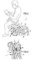
- This has the advantage of allowing the user to sit on the saddle of the bicycle in a folded and stable position, in particular when the user moves with the bicycle in the folded position in public transport such as a bicycle. bus or train and that all passenger seats are occupied, or that the user of the bicycle wishes to remain close to it.
- the front portion of the tube of the tubular structure located on the lateral side of the bicycle where the pedal is arranged has a curved shape configured to surround said pedal.
- This has the advantage of protecting the crankset when the bicycle is stabilized in the folded position.
- This also has the advantage of protecting the legs of the user of the bicycle when it pedal.
- This also has the advantage, in the folded position, of protecting the user and the environment likely to be in contact with the bicycle.
- the foldable bicycle object of the present invention comprises a transmission system which meshes with the pedal and with the rear wheel.
- the tubular structure disposed on the side of the crankset comprises an upper tube and a lower tube interconnected at their front end by a cylindrical tubular portion which surrounds the crankset, the upper and lower tubes and the cylindrical tubular portion surrounding the transmission system and being wider than the width of said transmission system, so as to cover said transmission system and facilitate assembly of the transmission system.
- the transmission system is preferably offset towards the inside of the bicycle relative to the upper and lower tubes and to the cylindrical tubular portion, so as to avoid contact with said transmission system. This avoids for example the user to take the pants legs in said transmission system when it pedal. This also has the advantage, in the folded position, of protecting the user and the environment likely to be in contact with the bicycle.
- the front portion of the tube of the tubular structure located on the lateral side of the bicycle opposite to that where is arranged the pedal, has a curved shape configured to allow manipulation with a hand of said bicycle in the folded position.
- the front portion of the tube also provides a handling function, the user can for example lift the front end of the rear part of the bicycle while keeping the rear wheel at the rear. ground contact, which allows to easily move said bicycle in the folded position, or even lift the bike with ease without the rear wheel being in contact with the ground.
- the tubes of the tubular structures disposed on each lateral side of the bicycle and therefore on each side of the seat tube are fixed together in their front portions, via a first transverse plate arranged in the lower part.
- the seat tube comprises a lower end which is fixed on the first transverse plate.
- the pedal is mounted on the seat tube in a portion between the upper tube and the lower tube of the tubular structure, the side side where is arranged said pedal.
- This mounting of the pedal on the seat tube is made independently of said upper and lower tubes and the cylindrical tubular portion.
- the front portions of the tubes disposed on each side of the bicycle are fixed together by means of a second transverse plate disposed in the upper part, the folding system being arranged on said second transverse plate.
- the second transverse plate is secured with the seat tube to enhance the rigidity of the bicycle frame.
- the front portions of the tubes arranged on each side side of the bicycle each comprise a protective piece configured to come into contact with the ground and protect said front portions when said foldable bicycle is in the folded position and stabilized on the ground.
- the tubular structures consist of tubes as such, hollow and circular. But we could also replace these tubes with solid bars having a circular, square, rectangular or triangular, or other. They may also be hollow rods having a rectangular or triangular section, or even others.
- the use of tubes with the advantages of lightening the frame of the bicycle.
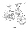
- the foldable bicycle 1 comprises a frame 2 which has a rear portion 3 and a front portion 4.
- the rear portion 3 comprises a seat tube 5 which extends more or less vertically as shown in FIG. figure 1 .
- This seat tube 5 slidably receives a seat post 6, clamping means being implemented between the seat post 6 and the seat tube 5 for locking between said elements according to the desired setting.
- This seat post 6 receives at its upper end a saddle 7.
- the rear portion 3 comprises two tubular structures 8, 9 disposed on each lateral side of the seat tube 5, as shown in FIG. figure 1 , that is to say on the lateral sides of the bicycle.
- the bicycle comprises a rear wheel 10 which is mounted pivotally connected along a transverse axis X1 on the bicycle.
- This assembly of the rear wheel is made with respect to the rear portions 8a, 9a of the two tubular structures 8, 9. figure 1 that the rear portion 3 receives a pedal 11 and a transmission system 12 may consist of a chain or a belt, this transmission system 12 being arranged between the pedal 11 and the rear wheel 10.
- the front part 4 of the bicycle 1 comprises a longitudinal tube 13, at the front end 13a of which is arranged a directional tube 14 which extends substantially vertically, with a slight inclination towards the rear, as illustrated on the figure 1 .
- This directional tube 14 receives in pivot connection along the longitudinal axis of said directional tube 14, a fork 15 at the lower end of which is mounted in pivot connection along an axis transverse to said fork 15, a front wheel 16.
- This fork 15 receives at its upper end a bracket 17 on which is mounted a handlebar 18.
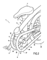
- FIG. 1 to 3 that a folding system 19 is arranged between the rear end 13b of the longitudinal tube 13 and the front portions 8b, 9b of the two tubular structures 8, 9.
- This folding system 19 makes it possible to fold the front part 4 against the rear part 3, as illustrated through the figure 3 .
- the axis of the front wheel 16 is substantially disposed coaxially with respect to the axis of the rear wheel 10, as illustrated in FIG. figure 3 .
- the front wheel 16 is slightly shifted upwards relative to the rear wheel 10, when the bicycle is folded.
- the figure 5 shows in detail a preferred design of the tubular structures 8, 9 implemented on each side side of the bicycle 1.
- These tubular structures 8, 9 comprise in their central portion 8c, 9c, an upper tube 21 and a lower tube 22.
- the rear ends 21a, 22a of the upper and lower tubes are fixed to a support plate 23 which comprises a groove 24 opening on the rear, which allows the attaching an end of the axis of the rear wheel 10, as it appears on the figure 1 .
- a support plate 23 which comprises a groove 24 opening on the rear, which allows the attaching an end of the axis of the rear wheel 10, as it appears on the figure 1 .
- the front ends 21b, 22b of the upper tubes 21 and lower 22 are fixed to a cylindrical tubular portion 25.
- the upper tube 21, the cylindrical tubular portion 25 and the lower tube 22 may be implemented by means of separate tubular elements fixed together, in particular by welding. However, it is possible to envisage the implementation of this upper tube 21, of this tubular portion 25 and of this lower tube 22, by means of one and the same tube which is bent over on itself.
- tubular structure 8 on the lateral side of the bicycle where the pedal 11 is located surrounds said pedal 11 as well as the transmission system 12.
- the tubular structure 9 on the lateral side of the bicycle, opposite to that where located the pedal 11, has a shape and dimensions identical to the first tubular structure 8.
- tubular structures 8, 9 comprise, at the supports 26, 27 of each of the cylindrical tubular portions 25, protective parts 26a, 27a configured to rest on the ground so as to avoid degradation of the tubular structures 8 , 9, when the bicycle, in the folded position, rests on the ground.
- a first plate 29 is fixed in particular by welding between the lower ends 25a of the cylindrical tubular portions 25 of the two tubular structures 8, 9, these lower ends 25a of the cylindrical tubular portions 25 being adjacent to the front ends 22b of the lower tubes 22.
- the lower end 5a of the seat tube 5 is fixed to this first transverse plate 29 arranged in the lower part.
- a second transverse plate 30, disposed in the upper part is fixed in particular by welding between the upper ends 25b of the cylindrical tubular portions 25 of the two tubular structures 8, 9.
- the upper ends 25b are adjacent to the front ends 21b of the upper tubes 21.
- this second transverse plate 30, disposed on the upper side receives the folding system 19 and is fixed, in particular by welding with the seat tube 5, more or less in the central part of said seat tube 5.
- the tubular structure 8 disposed on the lateral side where the pedal 11 is located is dimensioned so that the width of the upper tubes 21 and lower 22 and the cylindrical tubular portion 25 are greater than the width of the transmission system 12 consisting for example a belt or transmission chain. Moreover, as can be seen in particular on the figure 1 , this transmission system 12 is slightly shifted inwardly of the bicycle 1 relative to the tubular structure 8. This has the advantage of avoiding contact with the transmission system 12, especially with the legs during use of the bicycle 1.
- tubular structures 8 and 9 which are preferably identical for reasons of aesthetics, but may be of different design, but these different designs have a curved front portion making it possible to constitute the two supports. 26, 27 coming into contact with the ground when the bicycle is in bent position, so as to stabilize the bicycle 1.
- FIGS. Figures 6 and 7 it is possible to provide design variants as illustrated in FIGS. Figures 6 and 7 . We see on this figure 6 that the tubular structure 8, 9 has a design similar to that described above for the figure 5 on which however the upper tube 21 has been removed.
- tubular structure 8, 9 comprises a design similar to that of the figure 5 described above, in which however the lower tube 22 has been removed.
- cylindrical tubular portion 25 has a support 26, 27 coming into contact against the ground when the bicycle is in the folded position and stabilized on the ground, as illustrated in FIGS. figures 2 and 3 .
- tubular structures make it possible to lighten the frame of the bicycle.
- solid bars or hollow rods which have a cross section of a shape different from that of a circle such as for example a square, a rectangle, a triangle, according to the aesthetics that one wishes to give to the bicycle.
- the axis of the front wheel 16 When the bicycle 1 is in the folded position, the axis of the front wheel 16 is disposed either in the axis of the rear wheel 10 is slightly offset above the axis of the rear wheel 10, according to the design of the Folding system 19.
- Such folding systems 19 are known to those skilled in the art. It will be understood that when the axis of the front wheel 16 is arranged coaxially with respect to the axis of the rear wheel 10, the two front and rear wheels 16, 10 rest on the ground and, in combination with the two supports 26, 27 cylindrical tubular portions 25 of the two tubular structures 8, 9, a stabilization of the bicycle in the folded position.
Landscapes
- Engineering & Computer Science (AREA)
- Mechanical Engineering (AREA)
- Motorcycle And Bicycle Frame (AREA)
Abstract
Description
La présente invention concerne une bicyclette pliable ayant pour objet principal de faciliter la stabilisation de ladite bicyclette dans sa position pliée.The present invention relates to a foldable bicycle whose main object is to facilitate the stabilization of said bicycle in its folded position.
De manière connue, les bicyclettes pliables comprennent un cadre qui comporte notamment une partie arrière et une partie avant. La partie arrière comprend généralement une roue arrière, un tube de selle, une selle montée coulissante sur le tube de selle par le biais d'une tige de selle, un pédalier et un système de transmission, notamment du type chaine, agencé entre ladite roue arrière et ledit pédalier. De même, la partie avant comprend généralement un tube de direction recevant à pivotement une fourche à l'extrémité supérieure de laquelle est agencé un guidon et à l'extrémité inférieure de laquelle est agencée la roue avant. En outre, la bicyclette comprend un système de pliage qui est agencé entre la partie arrière et la partie avant en sorte de permettre le rabattement de ladite partie avant contre ladite partie arrière.In known manner, the foldable bicycles comprise a frame which comprises in particular a rear part and a front part. The rear part generally comprises a rear wheel, a seat tube, a saddle slidably mounted on the seat tube by means of a seat post, a pedal and a transmission system, in particular of the chain type, arranged between said wheel rear and said pedal. Similarly, the front portion generally comprises a steering tube pivotally receiving a fork at the upper end of which is arranged a handlebar and at the lower end of which is arranged the front wheel. In addition, the bicycle comprises a folding system which is arranged between the rear part and the front part so as to allow the folding of said front part against said rear part.
Un inconvénient principal des bicyclettes pliables porte sur la stabilisation de ladite bicyclette dans sa position pliée. A cet effet, certaines bicyclettes pliables, comme celles décrites dans le brevet européen publié sous le numéro
L'objet de la présente invention est de mettre en oeuvre un système de stabilisation de la bicyclette pliable lorsque celle-ci est dans sa position pliée, dont la conception, en comparaison aux bicyclettes pliables décrites dans les documents
A cet effet, l'invention concerne une bicyclette pliable comprenant un cadre qui comporte :
- une partie arrière sur laquelle sont agencés notamment une roue arrière, un tube de selle, une selle et un pédalier ;
- une partie avant sur laquelle sont agencés notamment un tube de direction, un guidon et une roue avant et ;
- un système de pliage agencé entre la partie arrière et la partie avant et configuré pour rabattre ladite partie avant contre ladite partie arrière.
- a rear part on which are arranged in particular a rear wheel, a seat tube, a saddle and a pedal;
- a front part on which are arranged in particular a steering tube, a handlebar and a front wheel and;
- a folding system arranged between the rear portion and the front portion and configured to fold said front portion against said rear portion.
De manière remarquable, selon la bicyclette pliable objet de la présente invention, la partie arrière comprend de chaque côté latéral de ladite bicyclette, une structure tubulaire comprenant au moins un tube s'étendant longitudinalement et comportant une portion arrière et une portion avant, des moyens d'assemblage étant agencés entre les portions arrière des tubes disposés de chaque coté latéral de la bicyclette et la roue arrière. En outre, les portions avant desdits tubes disposés de chaque coté latéral de la bicyclette ont une forme recourbée, configurée pour venir au contact du sol ou de la surface sur laquelle est disposée ladite bicyclette en position pliée, lorsque la partie avant est rabattue contre la partie arrière, en sorte que lesdites deux portions avant des structures tubulaires et au moins la roue arrière qui reposent sur le sol, stabilisent plus ou moins verticalement la bicyclette en position pliée.Remarkably, according to the foldable bicycle object of the present invention, the rear portion comprises on each side side of said bicycle, a tubular structure comprising at least one longitudinally extending tube and having a rear portion and a front portion, means assembly being arranged between the rear portions of the tubes arranged on each side side of the bicycle and the rear wheel. In addition, the front portions of said tubes arranged on each side side of the bicycle have a curved shape, configured to come into contact with the ground or the surface on which said bicycle is arranged in the folded position, when the front part is folded against the rear portion, so that said two front portions of the tubular structures and at least the rear wheel which rest on the ground, stabilize more or less vertically the bicycle in the folded position.
On comprend que selon la conception de la bicyclette objet de la présente invention, il n'est plus nécessaire de prévoir une béquille tel que cela est le cas selon les documents
En effet, selon l'invention, le rabattement de la partie avant contre la partie arrière permet de constituer systématiquement la stabilisation, de par la forme des portions avant des tubes qui permettent de constituer deux appuis avant sur le sol lorsque la partie arrière de la bicyclette en position pliée, est inclinée vers le bas par un pivotement de cette partie arrière par rapport à l'axe de la roue arrière, cette roue arrière assurant elle-même un appui arrière sur le sol.In fact, according to the invention, the folding of the front part against the rear part makes it possible systematically to form the stabilization, by the shape of the front portions of the tubes which make it possible to constitute two front supports on the ground when the rear part of the bicycle in the folded position, is inclined downwards by a pivoting of this rear portion relative to the axis of the rear wheel, the rear wheel itself ensuring a rear support on the ground.
En outre, les caractéristiques de la bicyclette pliable objet de l'invention telle que précitées, présentent pour avantages d'assurer une meilleure stabilisation de la bicyclette dans sa position pliée au niveau de l'extrémité avant de la partie arrière de la bicyclette, le tube de selle et la selle étant positionnés dans une zone située au-dessus de cette extrémité avant. Cela présente pour avantage, de permettre à l'utilisateur de s'asseoir sur la selle de la bicyclette en position pliée et stable, en particulier lorsque l'utilisateur se déplace avec la bicyclette en position pliée dans les transports en commun tels qu'un bus ou un train et que tous les sièges de passager sont occupés, voire que l'utilisateur de la bicyclette souhaite rester à proximité de celle-ci.In addition, the features of the foldable bicycle object of the invention as mentioned above, have the advantages of ensuring better stabilization of the bicycle in its folded position at the front end of the rear part of the bicycle, the seat tube and saddle being positioned in an area above this front end. This has the advantage of allowing the user to sit on the saddle of the bicycle in a folded and stable position, in particular when the user moves with the bicycle in the folded position in public transport such as a bicycle. bus or train and that all passenger seats are occupied, or that the user of the bicycle wishes to remain close to it.
Selon la bicyclette pliable objet de la présente invention, la portion avant du tube de la structure tubulaire située sur le côté latéral de la bicyclette où est agencé le pédalier, présente une forme recourbée configurée pour entourer ledit pédalier. Cela présente pour avantage de protéger le pédalier lorsque la bicyclette est stabilisée en position pliée. Cela présente également pour avantage de protéger les jambes de l'utilisateur de la bicyclette lorsque celui-ci pédale. Cela présente également comme avantage, en position pliée, de protéger l'utilisateur et l'environnement susceptible d'être en contact avec le vélo.According to the foldable bicycle object of the present invention, the front portion of the tube of the tubular structure located on the lateral side of the bicycle where the pedal is arranged, has a curved shape configured to surround said pedal. This has the advantage of protecting the crankset when the bicycle is stabilized in the folded position. This also has the advantage of protecting the legs of the user of the bicycle when it pedal. This also has the advantage, in the folded position, of protecting the user and the environment likely to be in contact with the bicycle.
Selon la bicyclette pliable objet de la présente invention, celle-ci comprend un système de transmission qui engrène avec le pédalier et avec la roue arrière. En outre, la structure tubulaire disposée du côté du pédalier comprend un tube supérieur et un tube inférieur reliés entre eux au niveau de leur extrémité avant par une portion tubulaire cylindrique qui entoure le pédalier, les tubes supérieur et inférieur et la portion tubulaire cylindrique entourant le système de transmission et étant de largeur supérieure à la largeur dudit système de transmission, en sorte de recouvrir ledit système de transmission et de faciliter l'assemblage du système de transmission. Cela présente pour avantage de protéger ledit système de transmission tant dans la position normale d'utilisation de la bicyclette que dans sa position pliée. Par ailleurs l'assemblage du système de transmission est facilité puisque sur les constructions traditionnelles, il y a croisement entre le système de transmission et le cadre, ce qui nécessite d'avoir un cadre ouvert lors de l'assemblage ou une chaîne en deux parties que l'on assemble après l'avoir croisé vis-à-vis du cadre.According to the foldable bicycle object of the present invention, it comprises a transmission system which meshes with the pedal and with the rear wheel. In addition, the tubular structure disposed on the side of the crankset comprises an upper tube and a lower tube interconnected at their front end by a cylindrical tubular portion which surrounds the crankset, the upper and lower tubes and the cylindrical tubular portion surrounding the transmission system and being wider than the width of said transmission system, so as to cover said transmission system and facilitate assembly of the transmission system. This has the advantage of protecting said transmission system both in the normal position of use of the bicycle as in its folded position. Furthermore, the assembly of the transmission system is facilitated because on traditional constructions, there is a cross between the transmission system and the frame, which requires having an open frame during assembly or a two-part chain that is assembled after having crossed it with respect to the frame.
Selon cette conception de la bicyclette pliable objet de l'invention, le système de transmission est de préférence déporté vers l'intérieur de la bicyclette par rapport aux tubes supérieur et inférieur et à la portion tubulaire cylindrique, en sorte d'éviter tout contact avec ledit système de transmission. Cela évite par exemple à l'utilisateur de se prendre les jambes de pantalon dans ledit système de transmission lorsque celui-ci pédale. Cela présente également comme avantage, en position pliée, de protéger l'utilisateur et l'environnement susceptible d'être en contact avec le vélo.According to this design of the foldable bicycle object of the invention, the transmission system is preferably offset towards the inside of the bicycle relative to the upper and lower tubes and to the cylindrical tubular portion, so as to avoid contact with said transmission system. This avoids for example the user to take the pants legs in said transmission system when it pedal. This also has the advantage, in the folded position, of protecting the user and the environment likely to be in contact with the bicycle.
Selon la bicyclette pliable objet de l'invention, la portion avant du tube de la structure tubulaire, située sur le côté latéral de la bicyclette opposé à celui où est agencé le pédalier, présente une forme recourbée configurée pour permettre la manipulation avec une main de ladite bicyclette en position pliée. Ainsi, outre la fonction de stabilisation de la bicyclette en position pliée, la portion avant du tube assure également une fonction de manipulation, l'utilisateur pouvant par exemple lever l'extrémité avant de la partie arrière de la bicyclette en conservant la roue arrière au contact du sol, ce qui permet de déplacer facilement ladite bicyclette en position pliée, voire soulever en toute facilité le vélo et ce sans que la roue arrière soit en contact avec le sol.According to the foldable bicycle object of the invention, the front portion of the tube of the tubular structure, located on the lateral side of the bicycle opposite to that where is arranged the pedal, has a curved shape configured to allow manipulation with a hand of said bicycle in the folded position. Thus, in addition to the stabilizing function of the bicycle in the folded position, the front portion of the tube also provides a handling function, the user can for example lift the front end of the rear part of the bicycle while keeping the rear wheel at the rear. ground contact, which allows to easily move said bicycle in the folded position, or even lift the bike with ease without the rear wheel being in contact with the ground.
Selon la bicyclette pliable objet de l'invention, les tubes des structures tubulaires disposés de chaque côté latéral de la bicyclette et par conséquent de chaque coté du tube de selle, sont fixés entre eux, dans leurs portions avant, par l'intermédiaire d'une première plaque transversale, disposée en partie inférieure. Selon cette conception de la bicyclette, le tube de selle comprend une extrémité inférieure qui est fixée sur la première plaque transversale.According to the foldable bicycle object of the invention, the tubes of the tubular structures disposed on each lateral side of the bicycle and therefore on each side of the seat tube, are fixed together in their front portions, via a first transverse plate arranged in the lower part. According to this design of the bicycle, the seat tube comprises a lower end which is fixed on the first transverse plate.
Selon la bicyclette pliable objet de l'invention, le pédalier est monté sur le tube de selle dans une portion située entre le tube supérieur et le tube inférieur de la structure tubulaire, du coté latéral où est agencé ledit pédalier. Ce montage du pédalier sur le tube de selle est réalisé indépendamment desdits tubes supérieur et inférieur et de la portion tubulaire cylindrique.According to the foldable bicycle object of the invention, the pedal is mounted on the seat tube in a portion between the upper tube and the lower tube of the tubular structure, the side side where is arranged said pedal. This mounting of the pedal on the seat tube is made independently of said upper and lower tubes and the cylindrical tubular portion.
Selon la bicyclette pliable objet de l'invention, les portions avant des tubes disposés de chaque coté de la bicyclette sont fixées entre elles par l'intermédiaire d'une seconde plaque transversale, disposée en partie supérieure, le système de pliage étant agencé sur ladite seconde plaque transversale. En outre, selon cette conception, la seconde plaque transversale est fixée avec le tube de selle pour renforcer la rigidité du cadre de la bicyclette.According to the foldable bicycle object of the invention, the front portions of the tubes disposed on each side of the bicycle are fixed together by means of a second transverse plate disposed in the upper part, the folding system being arranged on said second transverse plate. In addition, according to this design, the second transverse plate is secured with the seat tube to enhance the rigidity of the bicycle frame.
Selon la bicyclette pliable objet de l'invention, les portions avant des tubes disposés de chaque coté latéral de la bicyclette comprennent chacune une pièce de protection configurée pour venir au contact du sol et protéger lesdites portions avant lorsque ladite bicyclette pliable est en position pliée et stabilisée sur le sol.According to the foldable bicycle object of the invention, the front portions of the tubes arranged on each side side of the bicycle each comprise a protective piece configured to come into contact with the ground and protect said front portions when said foldable bicycle is in the folded position and stabilized on the ground.
Selon l'invention, les structures tubulaires sont constituées de tubes en tant que tels, creux et circulaires. Mais on pourrait également remplacer ces tubes par des barres pleines présentant une section circulaire, carrée, rectangulaire ou triangulaire, voire autres. Il peut également s'agir de tiges creuses présentant une section rectangulaire ou triangulaire, voire autres. L'utilisation de tubes ayant pour avantages d'alléger le cadre de la bicyclette.According to the invention, the tubular structures consist of tubes as such, hollow and circular. But we could also replace these tubes with solid bars having a circular, square, rectangular or triangular, or other. They may also be hollow rods having a rectangular or triangular section, or even others. The use of tubes with the advantages of lightening the frame of the bicycle.
Les caractéristiques de la présente invention apparaitront à la lecture de la description suivante d'un mode préférentiel de conception de la bicyclette pliable s'appuyant sur des figures parmi lesquelles :
- la
figure 1 illustre une vue d'ensemble de la bicyclette en condition d'utilisation ; - la
figure 2 illustre une vue partielle de la bicyclette en position pliée et stabilisée sur le sol ; - la
figure 3 illustre la bicyclette en position pliée et stabilisée sur le sol avec un utilisateur assis sur la selle ; - la
figure 4 illustre partiellement la bicyclette en position pliée et manipulée par un utilisateur ; - la
figure 5 illustre un mode préférentiel de conception de la structure tubulaire disposée sur les cotés latéraux de la bicyclette pliable, objet de l'invention ; - les
figures 6 et 7 illustrent deux variantes de conception de la structure tubulaire.
- the
figure 1 illustrates an overview of the bicycle in use condition; - the
figure 2 illustrates a partial view of the bicycle in the folded and stabilized position on the ground; - the
figure 3 illustrates the bicycle in a folded and stabilized position on the ground with a user sitting on the saddle; - the
figure 4 partially illustrates the bicycle in a folded and manipulated position by a user; - the
figure 5 illustrates a preferred mode of design of the tubular structure disposed on the lateral sides of the foldable bicycle object of the invention; - the
Figures 6 and 7 illustrate two design variants of the tubular structure.
Tel qu'illustré sur la
La bicyclette comprend une roue arrière 10 qui est montée en liaison pivot selon un axe transversal X1 sur la bicyclette. Cet assemblage de la roue arrière est réalisé par rapport aux portions arrières 8a, 9a des deux structures tubulaires 8, 9. On constate en outre sur cette
La partie avant 4 de la bicyclette 1 comprend un tube longitudinal 13, à l'extrémité avant 13a duquel est agencé un tube directionnel 14 qui s'étend sensiblement à la verticale, avec une légère inclinaison vers l'arrière, tel qu'illustré sur la
On constate notamment au regard des
La
On constate notamment sur la
Ces portions tubulaires cylindriques 25, au niveau de portions avant 8b, 9b des structures tubulaires 8, 9, permettent de constituer deux appuis 26, 27 qui permettent, tel qu'illustré sur les
On constate sur la
On constate en regard des
De même, on constate au travers des
On constate sur les
La structure tubulaire 8 disposée sur le côté latéral où se situe le pédalier 11 est dimensionnée en sorte que la largeur des tubes supérieur 21 et inférieur 22 ainsi que de la portion tubulaire cylindrique 25 soient supérieures à la largueur du système de transmission 12 constitué par exemple d'une courroie ou d'une chaîne de transmission. En outre, tel qu'on le constate notamment sur la
On constate sur la
D'autres caractéristiques peuvent être envisagées sans sortir du cadre de la présente invention. On peut notamment prévoir des variantes de conception des structures tubulaires 8 et 9 qui, de préférence, sont identiques pour des raisons d'esthétisme, mais peuvent être de conception différente, ces différentes conceptions présentant toutefois une portion avant recourbée permettant de constituer les deux appuis 26, 27 venant en contact contre le sol lorsque la bicyclette est en positon pliée, en sorte de stabiliser la bicyclette 1. On peut notamment prévoir des variantes de conception telles qu'illustrées aux
Dans la description qui précède, il est fait référence à des structures tubulaires. L'utilisation de tube permet d'alléger le cadre de la bicyclette. On pourrait toutefois envisager la mise en oeuvre de ce cadre, sans sortir de l'objet de la présente invention, en utilisant des barres pleines, voire des tiges creuses, qui présentent une section transversale de forme différente de celle d'un cercle tel que par exemple un carré, un rectangle, un triangle, selon l'esthétisme que l'on souhaite donner à la bicyclette.In the foregoing description, reference is made to tubular structures. The use of a tube makes it possible to lighten the frame of the bicycle. However, we could consider the implementation of this framework, without departing from the object of the present invention, using solid bars or hollow rods, which have a cross section of a shape different from that of a circle such as for example a square, a rectangle, a triangle, according to the aesthetics that one wishes to give to the bicycle.
Lorsque la bicyclette 1 est en position pliée, l'axe de la roue avant 16 est disposé soit dans l'axe de la roue arrière 10 soit légèrement décalé au dessus par rapport à l'axe de la roue arrière 10, selon la conception du système de pliage 19. De tels systèmes de pliage 19 sont connus de l'homme du métier. On comprend que lorsque l'axe de la roue avant 16 est disposé coaxialement par rapport à l'axe de la roue arrière 10, les deux roues avant et arrière 16, 10 reposent sur le sol et assurent en combinaison avec les deux appuis 26, 27 des portions tubulaires cylindriques 25 des deux structures tubulaires 8, 9, une stabilisation de la bicyclette en position pliée. Au contraire, lorsque l'axe de la roue avant 16 est décalé vers le haut par rapport à l'axe de la roue arrière 10, seule la roue arrière assure un point de contact au sol et stabilise la bicyclette en position pliée en combinaison avec les deux appuis 26, 27 des portions tubulaires cylindriques 25 des deux structures tubulaires 8, 9.When the
Claims (11)
Applications Claiming Priority (1)
| Application Number | Priority Date | Filing Date | Title |
|---|---|---|---|
| FR1061396A FR2969979B1 (en) | 2010-12-31 | 2010-12-31 | FOLDING BICYCLE WITH STABILIZATION SYSTEM |
Publications (1)
| Publication Number | Publication Date |
|---|---|
| EP2471700A1 true EP2471700A1 (en) | 2012-07-04 |
Family
ID=44060892
Family Applications (1)
| Application Number | Title | Priority Date | Filing Date |
|---|---|---|---|
| EP11193938A Withdrawn EP2471700A1 (en) | 2010-12-31 | 2011-12-16 | Folding bicycle with stabilisation system |
Country Status (5)
| Country | Link |
|---|---|
| US (1) | US20120169027A1 (en) |
| EP (1) | EP2471700A1 (en) |
| CN (1) | CN102616316A (en) |
| BR (1) | BRPI1106981A2 (en) |
| FR (1) | FR2969979B1 (en) |
Families Citing this family (2)
| Publication number | Priority date | Publication date | Assignee | Title |
|---|---|---|---|---|
| US10150529B2 (en) * | 2014-06-06 | 2018-12-11 | Bignay, Inc. | Vertically folding bicycle with locking mechanism |
| FR3090764B1 (en) * | 2018-12-21 | 2022-08-12 | Decathlon Sa | Hinge for folding bike |
Citations (6)
| Publication number | Priority date | Publication date | Assignee | Title |
|---|---|---|---|---|
| US5836602A (en) * | 1997-08-12 | 1998-11-17 | Wang; Ping-Tien | Collapsible bicycle |
| US20010004150A1 (en) * | 1999-12-20 | 2001-06-21 | Katsuichi Murayama | Folding bicycle |
| US6336649B1 (en) | 2000-03-02 | 2002-01-08 | Chin-Chuan Lin | Structure of foldable bicycle |
| FR2861048A1 (en) * | 2003-10-15 | 2005-04-22 | Bied Dominique | FOLDING BICYCLE AND FOLDING METHOD |
| EP1623916A1 (en) * | 2004-08-06 | 2006-02-08 | Hebie GmbH & Co.KG | Protective cover to shield a bicycle drive chain |
| EP1970296B1 (en) | 2007-03-14 | 2010-01-20 | I Shyong Lu | Foldable bicycle |
Family Cites Families (5)
| Publication number | Priority date | Publication date | Assignee | Title |
|---|---|---|---|---|
| US3354975A (en) * | 1966-02-10 | 1967-11-28 | Robert W Stuart | Foldable vehicle |
| US4448435A (en) * | 1981-02-12 | 1984-05-15 | Hon Corporation International | Foldable and portable vehicle |
| JP3680174B2 (en) * | 2002-01-25 | 2005-08-10 | 弘昌 趙 | Telescopic bicycle |
| CN1736793A (en) * | 2004-08-16 | 2006-02-22 | 唐山市蓝剑车业有限公司 | Completely folding shock absorption bicycle |
| JP4660276B2 (en) * | 2005-05-23 | 2011-03-30 | 一孝 北原 | Bicycle frame |
-
2010
- 2010-12-31 FR FR1061396A patent/FR2969979B1/en not_active Expired - Fee Related
-
2011
- 2011-12-16 EP EP11193938A patent/EP2471700A1/en not_active Withdrawn
- 2011-12-26 CN CN2011104412026A patent/CN102616316A/en active Pending
- 2011-12-28 BR BRPI1106981A patent/BRPI1106981A2/en not_active Application Discontinuation
- 2011-12-29 US US13/339,641 patent/US20120169027A1/en not_active Abandoned
Patent Citations (6)
| Publication number | Priority date | Publication date | Assignee | Title |
|---|---|---|---|---|
| US5836602A (en) * | 1997-08-12 | 1998-11-17 | Wang; Ping-Tien | Collapsible bicycle |
| US20010004150A1 (en) * | 1999-12-20 | 2001-06-21 | Katsuichi Murayama | Folding bicycle |
| US6336649B1 (en) | 2000-03-02 | 2002-01-08 | Chin-Chuan Lin | Structure of foldable bicycle |
| FR2861048A1 (en) * | 2003-10-15 | 2005-04-22 | Bied Dominique | FOLDING BICYCLE AND FOLDING METHOD |
| EP1623916A1 (en) * | 2004-08-06 | 2006-02-08 | Hebie GmbH & Co.KG | Protective cover to shield a bicycle drive chain |
| EP1970296B1 (en) | 2007-03-14 | 2010-01-20 | I Shyong Lu | Foldable bicycle |
Also Published As
| Publication number | Publication date |
|---|---|
| BRPI1106981A2 (en) | 2015-12-08 |
| FR2969979B1 (en) | 2013-02-08 |
| CN102616316A (en) | 2012-08-01 |
| US20120169027A1 (en) | 2012-07-05 |
| FR2969979A1 (en) | 2012-07-06 |
Similar Documents
| Publication | Publication Date | Title |
|---|---|---|
| EP0009439B1 (en) | Safety car seat for children | |
| EP0939019B1 (en) | Baby transporter | |
| EP1190963B1 (en) | Frame for supporting containers with cylindrical symmetry | |
| EP3390147B1 (en) | Cradle for children having an inner frame with an asymmetrical structure | |
| FR2882016A1 (en) | Umbrella-type folding stroller for carrying baby in e.g. city, has arms guided by rods between folded position in which arms form reduced angle with beam and unfolded position, and sliding unit mounted on beam to which one rod is integrated | |
| EP0900037A1 (en) | Chair consisting of interlocking elements | |
| EP3275771B1 (en) | Device for parking bicycles, and elements making it possible to constitute this device | |
| EP2247488A1 (en) | Bracket for the equipment of a rolling cart, particularly a shopping cart | |
| EP1931295B1 (en) | Folding wheelchair chassis and folding wheelchair | |
| EP2471700A1 (en) | Folding bicycle with stabilisation system | |
| EP2028974B1 (en) | Collapsible rest support | |
| EP1700769B1 (en) | Collapsible carriage for children with a release pedal | |
| EP1651506B1 (en) | Unit comprising a recipient and deployable subunits making it possible to form a scooter-type wheel vehicle | |
| FR3066469A1 (en) | FOLDING BIKE | |
| EP2178735B1 (en) | Convertible hammock stroller and corresponding hammock | |
| EP3044070A1 (en) | Foldable stroller that can be adapted for transporting new-borns | |
| FR2982166A1 (en) | Folding article i.e. golf cart for carrying golf bag, has connecting rods rotating in transverse plane of body and simultaneously pivoting support bars in transverse plane of main rod when main rod is pushed up relative to body | |
| FR2882253A1 (en) | Side arm coupling part for wheel chair, has bar traversing openings in walls of rigid part and serving as axis of rotation for fork arm and deck including winch equipped with handle for lifting fork arm at its rear end | |
| EP1004239B1 (en) | Torsion resistant rod rest | |
| FR2815010A1 (en) | FOLDING CYCLE | |
| FR2758247A1 (en) | School chair | |
| FR2585226A1 (en) | INDIVIDUAL FOLDING SEAT AND MULTIPLE SEAT REALIZED THEREFROM | |
| FR2878273A1 (en) | Multidirectional tubular scaffolding unit e.g. tubular pole, assembling device, has assembling part molded with four branches radially projecting relative to vertical unit or tubular pole and receiving ends of horizontal tubular unit | |
| WO2003042027A1 (en) | Bicycle frame convertible into a hammock support | |
| FR2793458A1 (en) | Foldable cycle carrier for rear of motor vehicle comprises two U-shaped frames and lock bar with hinges for pivoting and folding flat for storage |
Legal Events
| Date | Code | Title | Description |
|---|---|---|---|
| AK | Designated contracting states |
Kind code of ref document: A1 Designated state(s): AL AT BE BG CH CY CZ DE DK EE ES FI FR GB GR HR HU IE IS IT LI LT LU LV MC MK MT NL NO PL PT RO RS SE SI SK SM TR |
|
| AX | Request for extension of the european patent |
Extension state: BA ME |
|
| PUAI | Public reference made under article 153(3) epc to a published international application that has entered the european phase |
Free format text: ORIGINAL CODE: 0009012 |
|
| 17P | Request for examination filed |
Effective date: 20121113 |
|
| RIC1 | Information provided on ipc code assigned before grant |
Ipc: B62J 13/00 20060101ALI20121130BHEP Ipc: B62H 1/00 20060101AFI20121130BHEP Ipc: B62J 13/02 20060101ALI20121130BHEP Ipc: B62K 15/00 20060101ALI20121130BHEP |
|
| GRAP | Despatch of communication of intention to grant a patent |
Free format text: ORIGINAL CODE: EPIDOSNIGR1 |
|
| STAA | Information on the status of an ep patent application or granted ep patent |
Free format text: STATUS: THE APPLICATION IS DEEMED TO BE WITHDRAWN |
|
| 18D | Application deemed to be withdrawn |
Effective date: 20130528 |