EP1004239B1 - Torsion resistant rod rest - Google Patents
Torsion resistant rod rest Download PDFInfo
- Publication number
- EP1004239B1 EP1004239B1 EP99490038A EP99490038A EP1004239B1 EP 1004239 B1 EP1004239 B1 EP 1004239B1 EP 99490038 A EP99490038 A EP 99490038A EP 99490038 A EP99490038 A EP 99490038A EP 1004239 B1 EP1004239 B1 EP 1004239B1
- Authority
- EP
- European Patent Office
- Prior art keywords
- support
- central section
- lateral arm
- reinforcing bar
- lateral
- Prior art date
- Legal status (The legal status is an assumption and is not a legal conclusion. Google has not performed a legal analysis and makes no representation as to the accuracy of the status listed.)
- Expired - Lifetime
Links
Images

Classifications
-
- A—HUMAN NECESSITIES
- A01—AGRICULTURE; FORESTRY; ANIMAL HUSBANDRY; HUNTING; TRAPPING; FISHING
- A01K—ANIMAL HUSBANDRY; CARE OF BIRDS, FISHES, INSECTS; FISHING; REARING OR BREEDING ANIMALS, NOT OTHERWISE PROVIDED FOR; NEW BREEDS OF ANIMALS
- A01K97/00—Accessories for angling
- A01K97/10—Supports for rods
Definitions
- the present invention relates to a support for a fishing rod which has excellent resistance to torsion during use.
- Fishing rod holders are used by fishermen to spinning fishing, known as "landing", which consists of sending the far end of the line provided with a bait which is stuck on a hook and to bring it back quickly to shore, using a reel, when a fish appears to have taken the bait.
- fishing rods In general, fishermen use simultaneously several fishing rods fitted with reels which are arranged in waiting for any touches, on a support for fishing rod.
- the fishing rods arranged on this support are generally inclined, the portion grippable by the fisherman being oriented towards the ground so that the forces exerted by fish on the hook are more easily noticeable.
- the supports for fishing rod are, generally, constituted a central beam, substantially rectilinear, mounted on one foot and two support elements which are removably mounted at both ends of the central beam.
- Each support element consists of a small straight portion dividing into two curved branches which practically form a right angle with the straight portion and in which uprights slide vertical connected by a transverse bar commonly called "buzz bar" and which is equipped with fishing rod support members.
- a transverse bar commonly called "buzz bar”
- each support element is introduced into the central beam and a threaded rod which crosses the beam central unit keeps each of the elements in place support. By sliding the straight portion in the central beam, it is possible to adjust the spacing of the two support elements according to the length of fishing rods used.
- a first object of the present invention is to provide a support for fishing rod capable of withstanding the torsional forces liable to be generated during its use.
- each element support comprises a reinforcing bar which is transverse to the beam, and which is in contact with one of the lower or upper faces of the beam and at minus a straight post which is mounted on the reinforcement bar and which is substantially perpendicular to the beam; the reinforcement bar of at least one support elements being slidably mounted relative to the beam, according to the longitudinal axis of the beam and being provided with means for its blocking in position relative to the beam.
- the support element comprises a reinforcing bar and an amount substantially perpendicular to this reinforcement bar
- the forces twists generated during the use of the support of the invention, exercise substantially vertically with respect to the length of the bar reinforcement, thus giving the support of the invention better resistance to twists.
- the torsional forces are thus uniformly distributed over the entire length of the reinforcement bar which reduces their intensity per unit area.
- the reinforcing bar of at least one of the support elements being sliding on the beam, it is still possible, as in art modulate the spacing of the support elements according to the length of fishing rods used.
- the structure of the beam is not limiting of the invention.
- the support of the present invention may include a beam consisting of a alone or several parts assembled, full or partially cored.
- Another object of the invention is to provide a support for a cane peach that is likely to be compacted when not in use.
- this goal is achieved at means of a support which typically comprises a beam consisting of a central profile and two side arms, substantially straight which are removable and / or movable relative to the central profile so as to be able to be substantially superimposed on the central profile and which are suitable for be positioned in the extension of the central profile.
- Such a structure makes it possible to obtain a very compact support, when is disassembled due, on the one hand, to the rectilinear shape of the lateral arms which can easily form with the central profile, itself straight, by sliding, interlocking or pivoting, and therefore compact.
- the side arms can, at least be sufficiently close to the central profile so as to reduce the total space occupied by the support; the side arms can also be, partially or over their entire length, in contact with the central profile.
- each lateral arm is articulated with respect to the central profile along an axis of rotation transverse to the longitudinal axis of the central profile, such that each side arm can be folded over the central profile.
- the side arms can be completely folded over the central profile, possibly in opposite directions of rotation, or simply close to the central profile.
- the axis of rotation is not limited.
- This axis can take the form of a rod placed on or under the profile central, considering the support in its position of use, or a rod arranged in the thickness of the central profile, parallel to its width and cooperating with suitable openings made in the thickness of the central profile.
- each lateral arm is articulated relative to the central profile at by means of two nipples which each cooperate with an oblong opening which is arranged in the thickness of the central profile, so as to allow the sliding of the lateral arm relative to the central profile and so make the lateral arm movable in rotation relative to the central profile.
- this oblong opening opens at the end of the central profile, the nipples can be easily disengaged from the opening thus making the lateral arms removable.
- this second embodiment also includes means for locking the lateral arms in the extension of the profile central.
- blocking means can, for example, be plates of stop which, when the lateral arm is movable in rotation relative to the profile center, strike a surface of the central section, thus limiting the travel in rotation of the lateral arm so that at equilibrium, the stop plates being at contact of the central profile, the lateral arms are in the extension of the central profile.
- stop plate is meant, within the framework of the present invention, an insert or a portion of the side arm which is likely, for example, to be hollow.
- these blocking means include a stop plate secured to the lateral arm and possibly, depending on the direction of rotation of the lateral arm, means pressure of the stop plate on the central profile.
- the stop plate When the side arm is articulated in rotation so that under the effect of its own weight, it is positioned in the extension of the central profile, the stop plate will be placed so that under the effect of the weight of the arm lateral, it remains pressed against the central profile.
- the side arm is pivotable so that when positioned in the extension of the central profile, its own weight causes it to rotate to its folded position, means for pressing the stop plate against the central profile are then necessary.
- These means of pressure do not are not limiting of the invention.
- each of the lateral arms can be made from solid profiles or hollow, partially dug or having voids in their structure.
- each of the lateral arms comprises two sections which are substantially straight and parallel and spaced apart by a distance greater than the width of the central profile.
- the distance separating the two profiles from the lateral arm is slightly greater than the width of the central profile so that a once the side arm is positioned and locked in line with the profile central, said central section is fitted between the two sections of the lateral arm, which improves the rigidity of the side arms and therefore their resistance mechanical, in particular their resistance to torsional forces generated when handling fishing rods or when a fish pulls on the line of a fishing rod disposed on the support of the invention.
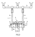
- the support 1 of the invention comprises a foot 2, removably mounted on the central section 3 of the beam P, by means of fixing means 2 a standards which allow to maintain the profile central 3, possibly in an inclined position.
- the beam P consists of a substantially straight central section 3 and provided with two rectilinear side arms 4 and 5 which are articulated at the ends 3 a and 3 b of the central section by means of articulation means 6 which will be more fully described later.
- the two ends 3 a and 3 b of the central section 3 are each secured to a lateral arm 4 and 5.
- the support elements 7 comprise a transverse bar 7 a and two vertical uprights 7 b .
- Figure 1 shows only one support element 7, that equipping the side arm 5. It is obvious that the side arm 4 can be equipped with a support element similar to the support element 7 whose description will follow with reference to the side arm 4.
- the transverse bar 7 a of the support element 7 is equipped with support members for one or more fishing rods 9.
- the support element 7 also includes a reinforcement bar 10.
- the reinforcement bar 10 is arranged in contact with the underside 5 d of the lateral arm 5 and is transverse to the lateral arm 5.
- Each of the two ends 10 a and 10 b of the reinforcement bar 10 is integral with a vertical upright 7 b which happens to be substantially perpendicular to the arm lateral 5 of the beam P, when the lateral arm 5 is in the extension of the central section 3.
- the reinforcing bar 10 comprises means 8 for its locking in position on the beam P.
- each vertical upright 7b is secured to one end 10 a, 10 b of the reinforcing bar 10 by means of a sleeve 11 wherein the amount 7 b is mounted sliding.
- the reinforcing bar 10 has a length slightly greater than the width of the lateral arm 5 so that the sleeves 11 are arranged on either side of the lateral arm 5 of the P-beam. In this way, the uprights 7 b can easily slide in the sleeves 11.
- the sleeves 11 also include means for blocking the upright 7 b which include, for example, levers 11 a which make it possible to maintain the upright 7 b in the sleeve 11, by friction between the internal surface of the sleeve 11 and the external surface of the upright 7 b .
- the uprights 7b are designed to be removable from the sleeves 11.
- the lateral arms 4 and 5 consist of two sections respectively 4 a , 4 b and 5 a , 5 b substantially straight and parallel ( Figure 1) and provided with transverse reinforcing rods 4 c and 5 c arranged towards the free end of each of the lateral arms 4 and 5.
- the sections 4 a , 4 b , 5 a and 5 b are spaced apart by a distance d greater than or equal to the width of the central section 3.
- the distance d will be very slightly greater than the width of the central section 3, to properly fit the central section 3 so as to reduce the possible torsional forces which can be exerted on each of the sections 4 a , 4b, 5 a and 5 b of the lateral arms 4 and 5.
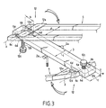
- each lateral arm 4 and 5 is articulated relative to the central section 3 along an axis of rotation z ( Figures 1 and 3), by means of two pins 6 a and 6 b ( Figure 3) forming the articulation means 6.
- Each nipples 6 a and 6 b enter an oblong opening 6 c formed in the thickness e of the central profile 3.
- the nipples 6 a and 6 b are therefore capable of sliding in the oblong openings 6 c , thus making the lateral arm 4 , 5 movable in translation relative to the central profile 3.
- the pins 6 a and 6 b can be replaced by a rod connecting the two profiles 4 a , 4 b and 5a, 5 b respectively of each of the lateral arms 4 and 5.
- the length h of the oblong openings 6 c is such that when the lateral arms 4 and 5 are locked in the extension of the central profile 3, the pins 6 a and 6 b coming into abutment against the end 6 d of the oblong openings 6 c which is directed towards the center of the strip 3, the strip 3 is inserted over a length L 1 ( Figure 1), of the order of 4cm to 5cm, respectively between the sections 4a, 4b and 5a, 5b each side arm 4 and 5 which makes it possible to reinforce the mechanical resistance, in particular nt to the twists of each lateral arm.
- the locking means 12 of the lateral arms in the extension of the central section 3 comprise, for each lateral arm 4 or 5, a stop plate 12 a secured to the lateral arm considered and means for pressing the plate stop 12 a on the central profile 3 which comprise a threaded rod 12 b which cooperates with a thread formed in the thickness of the central profile 3 or with an insert or a nut introduced into the central profile 3 and a pressure member, by example, wheel type 12 c .
- the blocking of the stop plate 12 a by the wheel 12 c can be achieved by wedging a small peripheral portion of the stop plate 12 a under the wheel 12 c .
- the stop plate 12 a comprises a cutout 12 d capable of cooperating with the threaded rod 12 b .
- the pressure is exerted substantially at the center of the stop plate 12 a and the blocking of the lateral arm 4 or 5 in the extension of the central section 3 is therefore reinforced.
- clamping pressure means which sandwich the stop plate 12a and the central profile 3 so as to hold the stop plate 12 a against the profile central 3.
- the pins 6 a and 6 b are placed so that the threaded rod 12 b is introduced into the opening 12 d (FIG. 1), the thumb wheel 12 c is then brought into contact with the stop plate 12 a by screwing the threaded rod 12 b .
- the wheel 12 c pressed sufficiently against the stop plate 12 a makes it possible to prevent the lateral arms 4 and 5 from moving either in translation or in rotation relative to the central profile 3.
- the pins 6 a and 6 b are abutted against the end 6 d of the oblong opening 6 c so as to maximize the length L 1 (FIG. 1) of the central section 3 embedded between the sections 4 a , 4 b and 5 a , 5 b of the two side arms 4 and 5.
- a first advantage concerns the fisherman who, in the case of removable lateral arms, can easily reassemble the support of the invention since the lateral arms are interchangeable.
- the second advantage is a reduction in the manufacturing cost of the support of the present invention.
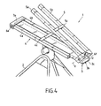
- the variant embodiment of the present invention which is shown in FIG. 4 has an articulation of the lateral arms produced by means of two rods 6 e and 6 f .
- the elements of this alternative embodiment common to the first embodiment shown in Figures 1 and 2 are referenced identically.
- the rod 6 a is integrated at the end 3 a of the central profile 3 and allows the articulation of the lateral arm 4 so that when the lateral arm 4 is folded over the central profile 3, the two profiles 4 a and 4 b are arranged on each side of the length of the central profile 3.
- the side arm 5 is articulated by means of a rod 6 f fixed on the central profile 3 so that when the side arm 5 is folded over the profile 3, it is located superimposed along its entire length on the central profile 3.
- each lateral arm 4, 5 is provided with locking means 12 in the extension of the central section 3 which comprise an abutment plate 12 a arranged so that, when each lateral arm is unfolded and under the effect of its own weight, the stop plate 12 a which is disposed at the end of each lateral arm 4 and 5 abuts against the central profile 3 or against a stop 3 c secured to the underside of the profile central 3, thus blocking the lateral arm 4 or 5 in the extension of the central profile 3.
- the advantage of this second embodiment is the fact of being able to completely fold back the lateral arms 4 and 5, without dismantling the foot 2 of the support 1 .
- the locking means in position 8 of the reinforcing bar 10 against the beam P comprise a reinforcing plate 8a disposed on the upper face 5 e of the lateral arm 5 opposite the face on which slides the reinforcement bar 10 and which at least partially covers the width of the lateral arm 5, so as to correctly block the reinforcement bar 10 against the lateral arm 5.
- the pressure means of the reinforcement plate 8a on the lateral arm 5 comprise a threaded rod 8b (FIG. 2) which secures the reinforcement bar 10 and the reinforcement plate 8a and which cooperates with a knurl 8c and a thread 8d formed in the thickness of the reinforcement bar 10.
- the thumb wheel 8 c when it is screwed into the reinforcement bar 10, exerts pressure on the reinforcement plate 8 a which keeps the latter pressed against the lateral arm 5. It is also possible, when the reinforcing bar 10 does not exhibit a sufficient thickness to provide the internal threaded rod 8b of a nut or a quick release cam.
- the reinforcement plate 8 a is provided with edges 8 e and 8 f ( Figure 2) which at least partially cover the thickness e 'of the sections 5 a , 5 b , serve as a guide for the sliding of the reinforcing bar 10 on the lateral arm 5 and which, also, prevent any rotation of the bar. reinforcement 10 relative to the lateral arm
- a spacer 8 g (FIG. 2) is arranged between the two sections 5 a , 5 b of the lateral arm 5.
- This spacer 8 g has a width L substantially equal to the distance d separating the sections 4 a and 4 b , and a height H less than or equal and, preferably, substantially equal to the thickness e ' of the sections 5 a , 5 b .
- the presence of this spacer 8 g makes it possible to stiffen the lateral arm 5 by forming a solid portion, therefore more resistance to torsion, at the level of the support element 7, which further reinforces the action of the reinforcing bar 10.
- L 'spacer 8 g is integral with the reinforcement plate 8 a and / or the reinforcement bar 10.
- the reinforcement bar 10 can, in all cases, when it is slidably mounted on the beam P , be detached from the beam P by sliding to the free end of the lateral arm 5.
- the arrangement of the reinforcing bar 10 and the reinforcing plate 8 a can be reversed, that is to say that the reinforcing bar 10 can be arranged on the face 5 e of the lateral arm 5 Likewise, it is possible to adapt the arrangement of the various elements of the first locking means 8 to a support element 7 comprising only a rectilinear upright 7b .
Landscapes
- Life Sciences & Earth Sciences (AREA)
- Environmental Sciences (AREA)
- Animal Husbandry (AREA)
- Biodiversity & Conservation Biology (AREA)
- Fishing Rods (AREA)
- Mutual Connection Of Rods And Tubes (AREA)
- Tents Or Canopies (AREA)
Abstract
Description
La présente invention concerne un support pour canne à pêche qui présente une excellente résistance aux torsions lors de son utilisation.The present invention relates to a support for a fishing rod which has excellent resistance to torsion during use.
Les supports pour canne à pêche sont utilisés par les pêcheurs pour la pêche au lancer, dite "au posé", qui consiste à envoyer au loin, l'extrémité de la ligne munie d'un appât qui est piqué sur un hameçon et à la ramener rapidement vers le rivage, au moyen d'un moulinet, lorsqu'un poisson semble avoir mordu à l'hameçon. En général, les pêcheurs utilisent simultanément plusieurs cannes à pêche munies de moulinets qui sont disposées, en attendant d'éventuelles touches, sur un support pour canne à pêche. Les cannes à pêche disposées sur ce support sont en général inclinées, la portion préhensible par le pêcheur étant orientée vers le sol de sorte que les forces exercées par les poissons sur l'hameçon sont plus facilement perceptibles.Fishing rod holders are used by fishermen to spinning fishing, known as "landing", which consists of sending the far end of the line provided with a bait which is stuck on a hook and to bring it back quickly to shore, using a reel, when a fish appears to have taken the bait. In general, fishermen use simultaneously several fishing rods fitted with reels which are arranged in waiting for any touches, on a support for fishing rod. The fishing rods arranged on this support are generally inclined, the portion grippable by the fisherman being oriented towards the ground so that the forces exerted by fish on the hook are more easily noticeable.
Les supports pour canne à pêche sont, généralement, constitués d'une poutre centrale, sensiblement rectiligne, montée sur un pied et de deux éléments support qui sont montés de façon amovible, aux deux extrémités de la poutre centrale.The supports for fishing rod are, generally, constituted a central beam, substantially rectilinear, mounted on one foot and two support elements which are removably mounted at both ends of the central beam.
Chaque élément support est constitué d'une petite portion rectiligne se divisant en deux branches courbes qui forment pratiquement un angle droit avec la portion rectiligne et dans lesquelles coulissent des montants verticaux reliés par une barre transversale appelée couramment "buzz barre" et qui est équipée d'organes de support de la canne à pêche. Chaque montant vertical coulissant dans une branche de l'élément support, il est donc possible de régler la hauteur de la barre transversale.Each support element consists of a small straight portion dividing into two curved branches which practically form a right angle with the straight portion and in which uprights slide vertical connected by a transverse bar commonly called "buzz bar" and which is equipped with fishing rod support members. Each vertical upright sliding in a branch of the support element, it is therefore possible to adjust the height of the crossbar.
En général, la portion rectiligne de chaque élément support est introduite dans la poutre centrale et une tige filetée qui traverse la poutre centrale permet de maintenir en place, par coincement, chacun des éléments support. En faisant coulisser la portion rectiligne dans la poutre centrale, il est possible de régler l'écartement des deux éléments support en fonction de la longueur des cannes à pêche utilisées. In general, the straight portion of each support element is introduced into the central beam and a threaded rod which crosses the beam central unit keeps each of the elements in place support. By sliding the straight portion in the central beam, it is possible to adjust the spacing of the two support elements according to the length of fishing rods used.
Lorsque l'utilisateur déplace une canne à pêche ou lorsque un poisson tire sur la ligne d'une canne à pêche disposée sur ce type de support, les forces ainsi créées, génèrent des torsions au niveau des branches des éléments support et également au niveau du point d'attache de chaque élément support à la poutre centrale, c'est-à-dire au niveau de la tige filetée qui bloque les portion rectilignes des éléments support. Bien que les forces exercées soit faibles, leur point d'application étant fort éloigné de la poutre centrale, leur moment est conséquent et les torsions ainsi engendrées sont donc considérables.When the user moves a fishing rod or when a fish pulls on the line of a fishing rod arranged on this type of support, the forces thus created, generate torsions at the level of branches of the support elements and also at the point of attachment of each support element to the central beam, that is to say at the level of the rod threaded which blocks the straight portions of the support elements. even though forces exerted is low, their point of application being far from the central beam, their moment is substantial and the torsions thus generated are therefore considerable.
Ces phénomènes de torsions créent des jeux au niveau des tiges filetées qui solidarisent les éléments support et la poutre centrale ; les cannes à pêche disposées sur un support endommagé sont donc trop facilement déstabilisées, au moindre mouvement de leur ligne, ce qui induit le pêcheur en erreur, en lui faisant prendre la moindre oscillation des cannes à pêche pour une touche. Pour pallier à ces phénomènes de torsions qui risquent d'endommager durablement la structure du support, on solidarise les deux branches des éléments support, l'une à l'autre, au moyen de tiges rigides qui sont disposées perpendiculairement aux branches de l'élément support. Ces tiges qui alourdissent la structure du support, permettent de limiter les torsions des branches mais restent inefficaces en ce qui concerne les torsions au niveau des tiges filetées qui solidarisent les éléments support et la poutre centrale. De ce fait, le support est bien souvent irrémédiablement détérioré au bout d'un certain temps d'utilisation.These torsional phenomena create clearance at the level of the rods threaded which join the support elements and the central beam; the fishing rods placed on a damaged support are therefore too easily destabilized, at the slightest movement of their line, which induces fisherman in error, making him take the slightest oscillation of the rods to fishing for a twist. To overcome these torsional phenomena which risk of lasting damage to the support structure, the two branches of the support elements, one to the other, by means of rods rigid which are arranged perpendicular to the branches of the element support. These rods which weigh down the structure of the support, allow limit the twists of the branches but remain ineffective with regard to twists at the threaded rods which secure the support elements and the central beam. As a result, the support is very often irremediably deteriorated after a certain period of use.
Un premier but de la présente invention est de proposer un support pour canne à pêche apte à résister au forces de torsions susceptibles d'être engendrées lors de son utilisation.A first object of the present invention is to provide a support for fishing rod capable of withstanding the torsional forces liable to be generated during its use.
Conformément à un premier mode de réalisation de l'invention, ce but est atteint au moyen d'un support pour une ou plusieurs cannes à pêche, du type comprenant, de manière connue, une poutre sur laquelle sont montés au moins deux éléments support d'une ou plusieurs cannes à pêche. De façon caractéristique, selon ce premier mode de réalisation, chaque élément support comporte une barre de renfort qui est transversale à la poutre, et qui est en contact avec une des faces inférieure ou supérieure de la poutre et au moins un montant rectiligne qui est monté sur la barre de renfort et qui est sensiblement perpendiculaire à la poutre ; la barre de renfort d'au moins l'un des éléments support étant montée coulissante par rapport à la poutre, selon l'axe longitudinal de la poutre et étant pourvue de moyens pour son blocage en position par rapport à la poutre.In accordance with a first embodiment of the invention, this object is reached by means of a support for one or more fishing rods, type comprising, in known manner, a beam on which are mounted at least two support elements for one or more fishing rods. Of characteristically, according to this first embodiment, each element support comprises a reinforcing bar which is transverse to the beam, and which is in contact with one of the lower or upper faces of the beam and at minus a straight post which is mounted on the reinforcement bar and which is substantially perpendicular to the beam; the reinforcement bar of at least one support elements being slidably mounted relative to the beam, according to the longitudinal axis of the beam and being provided with means for its blocking in position relative to the beam.
Contrairement aux supports de l'art antérieur, dans le cas du support de l'invention, du fait que l'élément support comporte une barre de renfort et un montant sensiblement perpendiculaire à cette barre de renfort, les forces de torsions, engendrées lors de l'utilisation du support de l'invention, s'exercent sensiblement verticalement par rapport à la longueur de la barre de renfort, conférant ainsi au support de l'invention, une meilleure résistance aux torsions. En effet, les forces de torsions sont ainsi uniformément réparties sur toute la longueur de la barre de renfort ce qui diminue leur intensité par unité de surface.Unlike the supports of the prior art, in the case of the support of the invention, because the support element comprises a reinforcing bar and an amount substantially perpendicular to this reinforcement bar, the forces twists, generated during the use of the support of the invention, exercise substantially vertically with respect to the length of the bar reinforcement, thus giving the support of the invention better resistance to twists. Indeed, the torsional forces are thus uniformly distributed over the entire length of the reinforcement bar which reduces their intensity per unit area.
Par ailleurs, la barre de renfort d'au moins un des éléments support étant coulissante sur la poutre, il est encore possible, comme dans l'art antérieur, de moduler l'écartement des éléments support en fonction de la longueur des cannes à pêche utilisées.Furthermore, the reinforcing bar of at least one of the support elements being sliding on the beam, it is still possible, as in art modulate the spacing of the support elements according to the length of fishing rods used.
La structure de la poutre n'est pas limitative de l'invention. En effet, le support de la présente invention peut comporter une poutre constituée d'une seule ou de plusieurs parties assemblées, pleines ou au partiellement évidées.The structure of the beam is not limiting of the invention. Indeed, the support of the present invention may include a beam consisting of a alone or several parts assembled, full or partially cored.
Un autre but de l'invention est de proposer un support pour canne à pêche qui est susceptible d'être rendu compact lorsqu'il n'est pas utilisé.Another object of the invention is to provide a support for a cane peach that is likely to be compacted when not in use.
Conformément à un second mode de réalisation, ce but est atteint au moyen d'un support qui de façon caractéristique comprend une poutre constituée d'un profilé central et deux bras latéraux, sensiblement rectilignes qui sont amovibles et/ou mobiles par rapport au profilé central en sorte de pouvoir être sensiblement superposés au profilé central et qui sont aptes à être positionnés dans le prolongement du profilé central.According to a second embodiment, this goal is achieved at means of a support which typically comprises a beam consisting of a central profile and two side arms, substantially straight which are removable and / or movable relative to the central profile so as to be able to be substantially superimposed on the central profile and which are suitable for be positioned in the extension of the central profile.
Une telle structure permet d'obtenir un support très compact, lorsqu'il est démonté du fait, d'une part, de la forme rectiligne des bras latéraux qui peuvent facilement former avec le profilé central, lui-même rectiligne, par coulissement, emboítement ou par pivotement, et donc peu encombrant. Par le terme "superposés", on entend, dans le cadre de la présente invention, que les bras latéraux peuvent, au moins être suffisamment rapprochés du profilé central en sorte de réduire l'espace total occupé par le support ; les bras latéraux peuvent également être, partiellement ou sur toute leur longueur, en contact avec le profilé central.Such a structure makes it possible to obtain a very compact support, when is disassembled due, on the one hand, to the rectilinear shape of the lateral arms which can easily form with the central profile, itself straight, by sliding, interlocking or pivoting, and therefore compact. Through the term "superimposed" means, in the context of the present invention, that the side arms can, at least be sufficiently close to the central profile so as to reduce the total space occupied by the support; the side arms can also be, partially or over their entire length, in contact with the central profile.
Selon une première variante de ce second mode de réalisation, chaque bras latéral est articulé par rapport au profilé central selon un axe de rotation transversal à l'axe longitudinal du profilé central, de telle sorte que chaque bras latéral peut être replié sur le profilé central. Selon la position de l'axe qui peut, traverser le profilé central ou être tangent à sa surface, les bras latéraux peuvent être totalement repliés sur le profilé central, éventuellement selon des sens de rotation opposés, ou être simplement rapprochés du profilé central.According to a first variant of this second embodiment, each lateral arm is articulated with respect to the central profile along an axis of rotation transverse to the longitudinal axis of the central profile, such that each side arm can be folded over the central profile. According to the position of the axis which can cross the central profile or be tangent to its surface, the side arms can be completely folded over the central profile, possibly in opposite directions of rotation, or simply close to the central profile.
Selon ce second mode de réalisation l'axe de rotation n'est pas limité. Cet axe peut prendre la forme d'une tige disposée sur ou sous le profilé central, en considérant le support dans sa position d'utilisation, ou d'une tige disposée dans l'épaisseur du profilé central, parallèle à sa largeur et coopérant avec des ouvertures adaptées, ménagées dans l'épaisseur du profilé central.According to this second embodiment, the axis of rotation is not limited. This axis can take the form of a rod placed on or under the profile central, considering the support in its position of use, or a rod arranged in the thickness of the central profile, parallel to its width and cooperating with suitable openings made in the thickness of the central profile.
Selon une seconde variante de réalisation de ce second mode de réalisation, chaque bras latéral est articulé par rapport au profilé central au moyen de deux tétons qui coopèrent chacun avec une ouverture oblongue qui est ménagée dans l'épaisseur du profilé central, en sorte de permettre le coulissement du bras latéral par rapport au profilé central et de façon à rendre le bras latéral mobile en rotation par rapport au profilé central. Par ailleurs, lorsque cette ouverture oblongue débouche au niveau de l'extrémité du profilé central, les tétons peuvent être facilement désengagés de l'ouverture rendant ainsi les bras latéraux amovibles.According to a second alternative embodiment of this second mode of embodiment, each lateral arm is articulated relative to the central profile at by means of two nipples which each cooperate with an oblong opening which is arranged in the thickness of the central profile, so as to allow the sliding of the lateral arm relative to the central profile and so make the lateral arm movable in rotation relative to the central profile. Through elsewhere, when this oblong opening opens at the end of the central profile, the nipples can be easily disengaged from the opening thus making the lateral arms removable.
De préférence, ce second mode de réalisation comporte également des moyens de blocage des bras latéraux dans le prolongement du profilé central. Ces moyens de blocage peuvent, par exemple, être des plaques de butée qui, lorsque le bras latéral est mobile en rotation par rapport au profilé central, heurtent une surface du profilé central, limitant ainsi la course en rotation du bras latéral de sorte qu'à l'équilibre, les plaques de butée étant au contact du profilé central, les bras latéraux se trouvent dans le prolongement du profilé central. Par plaque de butée, on entend, dans le cadre de la présente invention, une pièce rapportée ou une portion du bras latéral qui est susceptible, par exemple, d'être creux.Preferably, this second embodiment also includes means for locking the lateral arms in the extension of the profile central. These blocking means can, for example, be plates of stop which, when the lateral arm is movable in rotation relative to the profile center, strike a surface of the central section, thus limiting the travel in rotation of the lateral arm so that at equilibrium, the stop plates being at contact of the central profile, the lateral arms are in the extension of the central profile. By stop plate is meant, within the framework of the present invention, an insert or a portion of the side arm which is likely, for example, to be hollow.
Selon une variante préférée de réalisation de ces moyens de blocage, ils comprennent une plaque de butée solidaire du bras latéral et éventuellement, en fonction du sens de rotation du bras latéral, des moyens de pression de la plaque de butée sur le profilé central. En effet, lorsque le bras latéral est articulé en rotation en sorte que, sous l'effet de son propre poids, il vient se positionner dans le prolongement du profilé central, la plaque de butée sera placée de façon à ce que sous l'effet du poids du bras latéral, elle reste pressée contre le profilé central. En revanche, lorsque le bras latéral est pivotant de telle manière que, lorsqu'il est positionné dans le prolongement du profilé central, son propre poids l'entraíne en rotation jusqu'à sa position repliée, des moyens de pression de la plaque de butée contre le profilé central sont alors nécessaires. Ces moyens de pression ne sont pas limitatifs de l'invention.According to a preferred embodiment of these blocking means, they include a stop plate secured to the lateral arm and possibly, depending on the direction of rotation of the lateral arm, means pressure of the stop plate on the central profile. When the side arm is articulated in rotation so that under the effect of its own weight, it is positioned in the extension of the central profile, the stop plate will be placed so that under the effect of the weight of the arm lateral, it remains pressed against the central profile. However, when the side arm is pivotable so that when positioned in the extension of the central profile, its own weight causes it to rotate to its folded position, means for pressing the stop plate against the central profile are then necessary. These means of pressure do not are not limiting of the invention.
Les bras latéraux peuvent être réalisés à partir de profilés pleins ou creux, partiellement creusés ou présentant des vides dans leur structure. Selon un mode particulier de réalisation du second mode de réalisation, chacun des bras latéraux comprend deux profilés qui sont sensiblement rectilignes et parallèles et qui sont écartés l'un de l'autre d'une distance supérieure à la largeur du profilé central. De préférence, selon ce mode de réalisation particulier, la distance séparant les deux profilés du bras latéral est légèrement supérieure à la largeur du profilé central en sorte que, une fois le bras latéral positionné et bloqué dans le prolongement du profilé central, ledit profilé central est emboíté entre les deux profilés du bras latéral, ce qui permet d'améliorer la rigidité des bras latéraux et donc leur résistance mécanique, en particulier leur résistance aux forces de torsions générées lors de la manipulation des cannes à pêche ou par un poisson qui tire sur la ligne d'une canne à pêche disposée sur le support de l'invention.The lateral arms can be made from solid profiles or hollow, partially dug or having voids in their structure. According to a particular embodiment of the second embodiment, each of the lateral arms comprises two sections which are substantially straight and parallel and spaced apart by a distance greater than the width of the central profile. Preferably, according to this mode of particular embodiment, the distance separating the two profiles from the lateral arm is slightly greater than the width of the central profile so that a once the side arm is positioned and locked in line with the profile central, said central section is fitted between the two sections of the lateral arm, which improves the rigidity of the side arms and therefore their resistance mechanical, in particular their resistance to torsional forces generated when handling fishing rods or when a fish pulls on the line of a fishing rod disposed on the support of the invention.
La présente invention sera mieux comprise et ses caractéristiques et avantages apparaítront mieux à la lecture de la description qui suit et fait référence aux dessins annexés représentant le mode de réalisation préféré de la présente invention, présenté à titre d'exemple non limitatif, sur lesquels
- la figure 1 représente une vue générale du mode de réalisation préféré de l'invention;
- la figure 2 représente une vue en coupe verticale d'une variante de réalisation de l'élément support équipant le support représenté sur la figure 1;
- la figure 3 représente plus en détails, le profilé central du support de l'invention représenté sur les figures 1 et 2, lorsque celui-ci se trouve sensiblement dans sa configuration la moins encombrante ;
- la figure 4 représente une vue d'une variante de réalisation du mode de réalisation préféré de la présente invention, les bras latéraux étant partiellement repliés sur le profilé central.
- Figure 1 shows a general view of the preferred embodiment of the invention;
- 2 shows a vertical sectional view of an alternative embodiment of the support element fitted to the support shown in Figure 1;
- Figure 3 shows in more detail, the central section of the support of the invention shown in Figures 1 and 2, when it is substantially in its least bulky configuration;
- Figure 4 shows a view of an alternative embodiment of the preferred embodiment of the present invention, the side arms being partially folded over the central section.
En référence à la figure 1, le support 1 de l'invention comporte un pied
2, monté de façon amovible sur le profilé central 3 de la poutre P, par
l'intermédiaire de moyens de fixation 2a standards qui permettent de
maintenir le profilé central 3, éventuellement dans une position inclinée. La
poutre P est constituée d'un profilé central 3 sensiblement rectiligne et muni
des deux bras latéraux 4 et 5 rectilignes qui sont articulés au niveau des
extrémités 3a et 3b du profilé central par l'intermédiaire de moyens
d'articulation 6 qui seront plus amplement décrits ultérieurement. Les deux
extrémités 3a et 3b du profilé central 3 sont solidaires chacune d'un bras
latéral 4 et 5. Les éléments support 7 comprennent une barre transversale 7a
et deux montants verticaux 7b. La figure 1, ne représente qu'un seul élément
support 7, celui équipant le bras latéral 5. Il est bien évident, que le bras
latéral 4 peut être équipé d'un élément support similaire à l'élément support 7
dont la description va suivre en référence au bras latéral 4.Referring to Figure 1, the support 1 of the invention comprises a foot 2, removably mounted on the
La barre transversale 7a de l'élément support 7 est équipée
d'organes de support pour une ou plusieurs cannes à pêche 9. L'élément
support 7 comporte également une barre de renfort 10. La barre de renfort 10
est disposée, en contact avec la face inférieure 5d du bras latéral 5 et est
transversale au bras latéral 5. Chacune des deux extrémités 10a et 10b de la
barre de renfort 10 est solidaire d'un montant vertical 7b qui se trouve être
sensiblement perpendiculaire au bras latéral 5 de la poutre P, lorsque le bras
latéral 5 est dans le prolongement du profilé central 3. La barre de renfort 10
comporte des moyens 8 pour son blocage en position sur la poutre P.The
De préférence comme c'est le cas du mode de réalisation représenté
sur les figures 1 et 2 chaque montant vertical 7b est solidarisé à une
extrémité 10a, 10b de la barre de renfort 10 au moyen d'un manchon 11 dans
lequel le montant 7b est monté coulissant. Afin de permettre un réglage en
hauteur facile de la barre transversale 7a la barre de renfort 10 présente une
longueur légèrement supérieure à la largeur du bras latéral 5 en sorte que
les manchons 11 sont disposés de part et d'autre du bras latéral 5 de la
poutre P. De cette façon, les montants 7b peuvent facilement coulisser dans
les manchons 11. Les manchons 11 comportent également des moyens de
blocage du montant 7b qui comprennent, par exemple, des leviers 11 a qui
permettent de maintenir le montant 7b dans le manchon 11, par frottement
entre la surface interne du manchon 11 et la surface externe du montant 7b.
Avantageusement, les montants 7b sont conçus pour être amovibles des
manchons 11.Preferably as is the case of the embodiment shown in Figures 1 and 2 each vertical upright 7b is secured to one
Les bras latéraux 4 et 5 sont constitués de deux profilés
respectivement 4a, 4b et 5a, 5b sensiblement rectilignes et parallèles
(figure 1) et pourvus de tiges transverses de renfort 4c et 5c disposées vers
l'extrémité libre de chacun des bras latéraux 4 et 5. Les profilés 4a, 4b, 5a et
5b sont éloignés d'une distance d supérieure ou égale à la largeur du profilé
central 3. De préférence, la distance d sera très légèrement supérieure à la
largeur du profilé central 3, pour emboíter correctement le profilé central 3
de façon à réduire les éventuelles forces de torsion qui peuvent s'exercer sur
chacun des profilés 4a, 4b, 5a et 5b des bras latéraux 4 et 5.The
Selon une variante de ce mode de réalisation préféré chaque bras
latéral 4 et 5 est articulé par rapport au profilé central 3 selon un axe de
rotation z (figures 1 et 3), au moyens de deux tétons 6a et 6b (figure 3)
formant les moyens d'articulation 6 . Chaque tétons 6a et 6b pénètre dans
une ouverture oblongue 6c ménagée dans l'épaisseur e du profilé central 3.
Les tétons 6a et 6b sont donc susceptibles de coulisser dans les ouvertures
oblongues 6c, rendant ainsi le bras latéral 4, 5 mobile en translation par
rapport au profilé central 3. Les tétons 6a et 6b peuvent être remplacés par
une tige reliant les deux profilés 4a, 4b et 5a, 5b respectivement de chacun
de bras latéraux 4 et 5. La longueur h des ouvertures oblongues 6c est telle
que lorsque les bras latéraux 4 et 5 sont bloqués dans le prolongement du
profilé central 3, les tétons 6a et 6b arrivant en butée contre l'extrémité 6d
des ouvertures oblongues 6c qui est orientée vers le centre du profilé 3, le
profilé 3 se trouve inséré sur une longueur L1 (figure 1), de l'ordre de 4cm à
5cm, entre les profilés respectivement 4a, 4b et 5a, 5b de chaque bras latéral
4 et 5 ce qui permet de renforcer la résistance mécanique, notamment aux
torsions de chaque bras latéral.According to a variant of this preferred embodiment, each
En référence à la figure 3, les moyens de blocage 12 des bras
latéraux dans le prolongement du profilé central 3 comprennent pour chaque
bras latéral 4 ou 5, une plaque de butée 12a solidaire du bras latéral
considéré et des moyens de pression de la plaque de butée 12a sur le profilé
central 3 qui comprennent une tige fileté 12b qui coopère avec un filetage
ménagé dans l'épaisseur du profilé central 3 ou avec un insert ou un écrou
introduit dans le profilé central 3 et un organe de pression, par exemple, du
type molette 12c. Le blocage de la plaque de butée 12a par la molette 12c
peut être réalisé par coincement d'une faible portion périphérique de la
plaque de butée 12a sous la molette 12c. Néanmoins, de préférence, la
plaque de butée 12a comprend une découpe 12d apte à coopérer avec la
tige filetée 12b. De cette manière, la pression est exercée sensiblement au
centre de la plaque de butée 12a et le blocage du bras latéral 4 ou 5 dans le
prolongement du profilé central 3 est donc renforcé. Il est également
possible, sans sortir du cadre de la présente invention, d'utiliser des moyens
de pression formant pince qui prennent en sandwich la plaque de butée 12a
et le profilé central 3 de façon à maintenir la plaque de butée 12a contre le
profilé central 3.With reference to FIG. 3, the locking means 12 of the lateral arms in the extension of the
Lorsque les bras latéraux 4 et 5 sont bloqués dans le prolongement
du profilé central 3, les tétons 6a et 6b sont placés en sorte que la tige filetée
12b soit introduite dans l'ouverture 12d (figure 1), la molette 12c est alors
mise au contact avec la plaque de butée 12a par vissage de la tige fileté 12b.
La molette 12c suffisamment pressée contre la plaque de butée 12a permet
d'empêcher les bras latéraux 4 et 5 de se mouvoir soit en translation, soit en
rotation par rapport au profilé central 3. De préférence, les tétons 6a et 6b
sont mis en butée contre l'extrémité 6d de l'ouverture oblongue 6c de façon à
maximiser la longueur L1 (figure 1) du profilé central 3 encastrée entre les
profilés 4a, 4b et 5a, 5b des deux bras latéraux 4 et 5.When the
La combinaison de l'ouverture oblongue 6c avec la plaque de butée
12a permet d'utiliser des bras latéraux 4 et 5 ayant strictement la même
structure, en dépit de leur sens de rotation opposés. Il en résulte deux
avantages. Un premier avantage concerne le pêcheur qui, dans le cas de
bras latéraux amovibles, peut remonter facilement le support de l'invention
puisque les bras latéraux sont interchangeables. Le second avantage est une
diminution du coût de fabrication du support de la présente invention.The combination of the
La variante de réalisation de la présente invention qui est représenté
sur la figure 4, présente une articulation des bras latéraux réalisée au moyen
de deux tiges 6e et 6f. Les éléments de cette variante de réalisation
communs au premier mode de réalisation représenté sur les figures 1 et 2
sont référencés à l'identique. La tige 6a est intégrée à l'extrémité 3a du profilé
central 3 et permet l'articulation du bras latéral 4 en sorte que lorsque le bras
latéral 4 est replié sur le profilé central 3, les deux profilés 4a et 4b sont
disposés de chaque coté de la longueur du profilé central 3. Le bras latéral 5
est articulé au moyen d'une tige 6f fixée sur le profilé central 3 de sorte que
lorsque le bras latéral 5 est replié sur le profilé 3, il se trouve superposé selon
toute sa longueur sur le profilé central 3.The variant embodiment of the present invention which is shown in FIG. 4 has an articulation of the lateral arms produced by means of two
Selon le mode de réalisation de la figure 4, chaque bras latéral 4, 5
est muni de moyens de blocage 12 dans le prolongement du profilé central 3
qui comprennent une plaque de butée 12a disposée en sorte que, lorsque
chaque bras latéral est déplié et sous l'effet de son propre poids, la plaque
de butée 12a qui est disposée à l'extrémité de chaque bras latéral 4 et 5 vient
en butée contre le profilé central 3 ou contre une butée 3c solidaire de la face
inférieure du profilé central 3, bloquant ainsi le bras latéral 4 ou 5 dans le
prolongement du profilé central 3. L'avantage de ce second mode de
réalisation est le fait de pouvoir entièrement replier les bras latéraux 4 et 5,
sans démonter le pied 2 du support 1.According to the embodiment of FIG. 4, each
En référence aux figures 1 et 2, les moyens de blocage en position 8
de la barre de renfort 10 contre la poutre P comportent une plaque de renfort
8a disposée sur la face supérieure 5e du bras latéral 5 opposée à la face sur
laquelle coulisse la barre de renfort 10 et qui recouvre au moins partiellement
la largeur du bras latéral 5, de façon à bloquer correctement la barre de
renfort 10 contre le bras latéral 5.Referring to Figures 1 and 2, the locking means in
Les moyens de pression de la plaque de renfort 8a sur le bras latéral
5 comportent une tige fileté 8b (figure 2) qui solidarise la barre de renfort 10
et la plaque de renfort 8a et qui coopère avec une molette 8c et un filetage 8d
ménagé dans l'épaisseur de la barre de renfort 10. La molette 8c, lorsqu'elle
est vissée dans la barre de renfort 10, exerce une pression sur la plaque de
renfort 8a qui maintient cette dernière appuyée contre le bras latéral 5. Il est
également possible, lorsque la barre de renfort 10 ne présente pas une
épaisseur interne suffisante de munir la tige filetée 8b d'un écrou ou d'une
serrage rapide à excentrique.The pressure means of the
De préférence, afin de mieux solidariser les profilés 5a et 5b du bras
latéral 5 et d'augmenter le blocage de la barre de renfort 10 sur la poutre P,
la plaque de renfort 8a est pourvue de bords 8e et 8f (figure 2) qui recouvrent
au moins partiellement l'épaisseur e' des profilés 5a, 5b, servent de guide au
coulissement de la barre de renfort 10 sur le bras latéral 5 et qui, également,
empêchent toute rotation de la barre de renfort 10 par rapport au bras latéralPreferably, in order to better secure the
5 Une entretoise 8g (figure 2) est disposée entre les deux profilés 5a, 5b
du bras latéral 5. Cette entretoise 8g présente une largeur L sensiblement
égale à la distance d séparant les profilés 4a et 4b, et une hauteur H
inférieure ou égale et, de préférence, sensiblement égale à l'épaisseur e' des
profilés 5a, 5b. La présence de cette entretoise 8g permet de rigidifier le bras
latéral 5 en formant une portion pleine, donc plus résistance aux torsions, au
niveau de l'élément support 7, ce qui renforce encore l'action de la barre de
renfort 10. L'entretoise 8g est solidaire de la plaque de renfort 8a et/ou de la
barre de renfort 10. Il est également possible de disposer plusieurs
entretoises 8g qui s'emboítent les unes dans les autres en sorte de rigidifier
le bras latéral 5. La présence de cette entretoise 8g n'empêche pas
l'amovibilité de la barre de renfort de la poutre P. En effet, la barre de renfort
10 peut, dans tous les cas, lorsqu'elle est montée coulissante sur la poutre P,
être désolidarisée de la poutre P par coulissement jusqu'à l'extrémité libre du
bras latéral 5.5 A
Selon l'invention, la disposition de la barre de renfort 10 et de la
plaque de renfort 8a peut être inversée, c'est-à-dire que la barre de renfort 10
peut être disposée sur la face 5e du bras latéral 5. De même, il est possible
d'adapter la disposition des différents éléments des premiers moyens de
blocage 8 à un élément support 7 ne comportant qu'un montant rectiligne 7b.According to the invention, the arrangement of the reinforcing
Claims (13)
- Support (1) for one or more fishing rods, of the type comprising a beam (P) on which are mounted at least two support elements (7) for one or more fishing rods, characterised in that each support element (7) includes a reinforcing bar (10) which is transverse to the beam (P) and which is in contact with one of the lower (4d) or upper (4e) faces of the beam (P), and at least one rectilinear post (7b) which is mounted on the reinforcing bar (10) and which is approximately perpendicular to the beam (P), and in that the reinforcing bar (10) of at least one of the support elements (7) is mounted sliding relative to the beam (P) along the longitudinal axis of the beam (P) and is provided with means (8) for locking in position relative to the beam (P).
- Support (1) according to claim 1, characterised in that the beam comprises:a central section (3);two lateral arms (4,5) which are substantially rectilinear and are detachable and/or mobile relative to the central section (3) so as to be able to be substantially superposed on the central section (3), and which are capable of being positioned in the extension of the central section (3).
- Support (1) according to claim 2, characterised in that each lateral arm (4, 5) is articulated relative to the central section (3) along an axis of rotation (z) which is transverse to the longitudinal axis of the central section (3) in such a way that each lateral arm (4, 5) can be folded over the central section (3) or aligned in the extension of the central section.
- Support (1) according to claim 2, characterised in that each lateral arm (4, 5) is articulated relative to the central section (3) by means of two lugs (6a, 6b) which each cooperate with an oblong opening (6c) which is provided in the thickness (e) of the central section (3) in such a way as to permit possibly the sliding of the two lateral arms (4, 5) relative to the central section (3) and so as to make each of the lateral arms (4,5) mobile in rotation relative to the central section (3).
- Support according to any one of claims 2 to 4, characterised in that it also includes means (12) for locking the lateral arm in the extension of said central section (3), said means comprising:a stop plate (12a) immovably attached to the lateral arm (4,5); and, possibly,means (12b, 12c, 12d) for pressing the stop plate (12a) against the central section (3).
- Support (1) according to any one of claims 2 to 5, characterised in that each of the lateral arms (4, 5) comprises two sections (4a, 4b, 5a, 5b) which are substantially rectilinear and parallel and which are spaced apart from one another by a distance (d).
- Support according to claim 6, characterised in that the distance (d) separating the two sections (4a, 4b, 5a, 5b) of the lateral arm (4, 5) is slightly greater than the width (1) of the central section (3) so that, once the lateral arm (4, 5) is positioned and locked in the extension of the central section (3), said central section (3) fits between the two sections (4a, 4b, 5a, 5b) of the lateral arm (4, 5).
- Support (1) according to claim 6 or 7, characterised in that the reinforcing base (10) includes a crosspiece (8g) which is disposed between the parallel sections (4a, 4b, 5a, 5b), the width (L) of the crosspiece (8g) being roughly equal to the distance (d) separating the two parallel sections (4a, 4b, 5a, 5b).
- Support (1) according to any one of claims 1 to 8, characterised in that the support element (7) can be detached from the beam (P).
- Support (1) according to one of claims 1 to 9, characterised in that each support element (7) includes two vertical posts (7b), each of the vertical posts (7b) being immovably attached to one end (10a, 10b) of the reinforcing bar (10).
- Support (1) according to one of claims 1 to 10, characterised in that the reinforcing bar (10) includes at each of its ends (10a, 10b) a sleeve (11) in which one of the posts (8) of the support element (7) is mounted sliding and which is equipped with means (11a) for locking the post (8), said sleeves (11) being disposed on either side of the beam (P).
- Fishing rod support (1) according to one of claims 1 to 11, characterised in that the means (8) for locking the reinforcing bar (10) in position relative to the beam (P) include a reinforcing plate (8a) disposed on the face of the beam (P) which is opposite the beam face on which the reinforcing bar (10) slides, and means (8b, 8c) for pressing the reinforcing plate (13) onto the beam (P).
- Support (1) according to claim 12, characterised in that the reinforcing plate (8a) includes edges (8e, 8f) which cover at least partially the thickness (e) of the beam (P).
Applications Claiming Priority (4)
| Application Number | Priority Date | Filing Date | Title |
|---|---|---|---|
| FR9815154A FR2786366B1 (en) | 1998-11-27 | 1998-11-27 | SUPPORT FOR FISHING ROD |
| FR9815153A FR2786365B1 (en) | 1998-11-27 | 1998-11-27 | SUPPORT FOR TORSION RESISTANT FISHING ROD |
| FR9815154 | 1998-11-27 | ||
| FR9815153 | 1998-11-27 |
Publications (2)
| Publication Number | Publication Date |
|---|---|
| EP1004239A1 EP1004239A1 (en) | 2000-05-31 |
| EP1004239B1 true EP1004239B1 (en) | 2003-09-17 |
Family
ID=26234684
Family Applications (1)
| Application Number | Title | Priority Date | Filing Date |
|---|---|---|---|
| EP99490038A Expired - Lifetime EP1004239B1 (en) | 1998-11-27 | 1999-11-25 | Torsion resistant rod rest |
Country Status (3)
| Country | Link |
|---|---|
| EP (1) | EP1004239B1 (en) |
| AT (1) | ATE249737T1 (en) |
| DE (1) | DE69911351T2 (en) |
Families Citing this family (2)
| Publication number | Priority date | Publication date | Assignee | Title |
|---|---|---|---|---|
| US9090214B2 (en) | 2011-01-05 | 2015-07-28 | Orbotix, Inc. | Magnetically coupled accessory for a self-propelled device |
| US20200037594A1 (en) * | 2018-08-03 | 2020-02-06 | Kevin F. Lohmeier | Fishing rod holder |
Family Cites Families (5)
| Publication number | Priority date | Publication date | Assignee | Title |
|---|---|---|---|---|
| GB2201322B (en) * | 1987-02-18 | 1991-08-28 | K M Tackle Developments Limite | Rod support unit for anglers |
| GB8911231D0 (en) * | 1989-05-16 | 1989-07-05 | Thornhill Alan | Fishing bite indicator |
| GB2306092A (en) * | 1995-10-14 | 1997-04-30 | Nash Kevin Tackle Ltd | Fishing rod support |
| GB2313030B (en) * | 1996-05-17 | 2000-01-19 | James Leary | Fishing rod rests |
| GB2321580B (en) * | 1997-01-24 | 1998-12-16 | Spring Sunglow Ind Co Ltd | Fishing kit |
-
1999
- 1999-11-25 EP EP99490038A patent/EP1004239B1/en not_active Expired - Lifetime
- 1999-11-25 AT AT99490038T patent/ATE249737T1/en not_active IP Right Cessation
- 1999-11-25 DE DE69911351T patent/DE69911351T2/en not_active Expired - Fee Related
Also Published As
| Publication number | Publication date |
|---|---|
| EP1004239A1 (en) | 2000-05-31 |
| DE69911351D1 (en) | 2003-10-23 |
| DE69911351T2 (en) | 2004-06-24 |
| ATE249737T1 (en) | 2003-10-15 |
Similar Documents
| Publication | Publication Date | Title |
|---|---|---|
| EP0561774A1 (en) | Collapsible wheelchair. | |
| WO1997036520A1 (en) | Chair consisting of interlocking elements | |
| EP1004239B1 (en) | Torsion resistant rod rest | |
| EP1721550B1 (en) | Patient bed with a complete side rail | |
| FR2475871A3 (en) | SUPPORT ARM FOR SEAT OR ARMCHAIR COMPRISING A RELEVABLE ARMREST | |
| EP0783856B1 (en) | Slatted bed base | |
| EP1488770A1 (en) | Stand-up chair with self-modifying tilting of the backrest | |
| EP0582551A1 (en) | Skiboot of plastics material | |
| EP0681799B1 (en) | Blocking device for an extension relative to a piece of furniture, and piece of furniture equipped with it | |
| FR2786366A1 (en) | Fishing rod support which resists torsion has reinforcing bar transverse to beam and in contact with one of lower or upper beam faces | |
| EP2862440B1 (en) | Pole roller | |
| FR2786365A1 (en) | Fishing rod support which resists torsion has reinforcing bar transverse to beam and in contact with one of lower or upper beam faces | |
| EP0045679A1 (en) | Transformable seat | |
| EP0282385B1 (en) | Device for anchoring at rafters for roof works | |
| FR2685606A1 (en) | Fishing stool with rod(s) support | |
| EP2471700A1 (en) | Folding bicycle with stabilisation system | |
| FR2815527A1 (en) | Hospital bed has safety barriers fitted along one side which can be slid together to occupy half of side or extended along whole side, joint between two sections allowing them to be mounted at angle when section of bed is raised | |
| FR2686940A3 (en) | Folding structure which can be used as a gangway and/or ladder | |
| EP0945568B1 (en) | Individual windshelter | |
| FR2758247A1 (en) | School chair | |
| FR2844689A1 (en) | Convertible seat can be arranged in long or short form or as bed and has frame with telescopic sides, mattress having sleeve on its underside which fits on to hoop attached to end of frame when seat is shortened | |
| BE879829A (en) | TRANSATLANTIC TYPE SEAT | |
| FR2684310A1 (en) | ADJUSTABLE ROCKER, IN PARTICULAR FOR TOYS. | |
| FR2771268A1 (en) | Folding chair with transversal slats | |
| FR2498869A1 (en) | Record player head for supporting module - contains piezoelectric system and with which stylus carrying stirrup slidingly engages, maintained by cross-members |
Legal Events
| Date | Code | Title | Description |
|---|---|---|---|
| PUAI | Public reference made under article 153(3) epc to a published international application that has entered the european phase |
Free format text: ORIGINAL CODE: 0009012 |
|
| AK | Designated contracting states |
Kind code of ref document: A1 Designated state(s): AT BE CH CY DE DK ES FI FR GB GR IE IT LI LU MC NL PT SE |
|
| AX | Request for extension of the european patent |
Free format text: AL;LT;LV;MK;RO;SI |
|
| 17P | Request for examination filed |
Effective date: 20000731 |
|
| AKX | Designation fees paid |
Free format text: AT BE CH CY DE DK ES FI FR GB GR IE IT LI LU MC NL PT SE |
|
| 17Q | First examination report despatched |
Effective date: 20030115 |
|
| GRAH | Despatch of communication of intention to grant a patent |
Free format text: ORIGINAL CODE: EPIDOS IGRA |
|
| GRAS | Grant fee paid |
Free format text: ORIGINAL CODE: EPIDOSNIGR3 |
|
| GRAA | (expected) grant |
Free format text: ORIGINAL CODE: 0009210 |
|
| AK | Designated contracting states |
Kind code of ref document: B1 Designated state(s): AT BE CH CY DE DK ES FI FR GB GR IE IT LI LU MC NL PT SE |
|
| PG25 | Lapsed in a contracting state [announced via postgrant information from national office to epo] |
Ref country code: IE Free format text: LAPSE BECAUSE OF FAILURE TO SUBMIT A TRANSLATION OF THE DESCRIPTION OR TO PAY THE FEE WITHIN THE PRESCRIBED TIME-LIMIT Effective date: 20030917 Ref country code: FI Free format text: LAPSE BECAUSE OF FAILURE TO SUBMIT A TRANSLATION OF THE DESCRIPTION OR TO PAY THE FEE WITHIN THE PRESCRIBED TIME-LIMIT Effective date: 20030917 Ref country code: AT Free format text: LAPSE BECAUSE OF FAILURE TO SUBMIT A TRANSLATION OF THE DESCRIPTION OR TO PAY THE FEE WITHIN THE PRESCRIBED TIME-LIMIT Effective date: 20030917 |
|
| REG | Reference to a national code |
Ref country code: GB Ref legal event code: FG4D Free format text: NOT ENGLISH |
|
| REG | Reference to a national code |
Ref country code: CH Ref legal event code: EP |
|
| GBT | Gb: translation of ep patent filed (gb section 77(6)(a)/1977) | ||
| REF | Corresponds to: |
Ref document number: 69911351 Country of ref document: DE Date of ref document: 20031023 Kind code of ref document: P |
|
| REG | Reference to a national code |
Ref country code: IE Ref legal event code: FG4D Free format text: FRENCH |
|
| PG25 | Lapsed in a contracting state [announced via postgrant information from national office to epo] |
Ref country code: LU Free format text: LAPSE BECAUSE OF NON-PAYMENT OF DUE FEES Effective date: 20031125 Ref country code: CY Free format text: LAPSE BECAUSE OF FAILURE TO SUBMIT A TRANSLATION OF THE DESCRIPTION OR TO PAY THE FEE WITHIN THE PRESCRIBED TIME-LIMIT Effective date: 20031125 |
|
| PG25 | Lapsed in a contracting state [announced via postgrant information from national office to epo] |
Ref country code: MC Free format text: LAPSE BECAUSE OF NON-PAYMENT OF DUE FEES Effective date: 20031130 Ref country code: LI Free format text: LAPSE BECAUSE OF NON-PAYMENT OF DUE FEES Effective date: 20031130 Ref country code: CH Free format text: LAPSE BECAUSE OF NON-PAYMENT OF DUE FEES Effective date: 20031130 |
|
| PG25 | Lapsed in a contracting state [announced via postgrant information from national office to epo] |
Ref country code: SE Free format text: LAPSE BECAUSE OF FAILURE TO SUBMIT A TRANSLATION OF THE DESCRIPTION OR TO PAY THE FEE WITHIN THE PRESCRIBED TIME-LIMIT Effective date: 20031217 Ref country code: GR Free format text: LAPSE BECAUSE OF FAILURE TO SUBMIT A TRANSLATION OF THE DESCRIPTION OR TO PAY THE FEE WITHIN THE PRESCRIBED TIME-LIMIT Effective date: 20031217 Ref country code: DK Free format text: LAPSE BECAUSE OF FAILURE TO SUBMIT A TRANSLATION OF THE DESCRIPTION OR TO PAY THE FEE WITHIN THE PRESCRIBED TIME-LIMIT Effective date: 20031217 |
|
| PG25 | Lapsed in a contracting state [announced via postgrant information from national office to epo] |
Ref country code: PT Free format text: LAPSE BECAUSE OF FAILURE TO SUBMIT A TRANSLATION OF THE DESCRIPTION OR TO PAY THE FEE WITHIN THE PRESCRIBED TIME-LIMIT Effective date: 20031226 |
|
| PG25 | Lapsed in a contracting state [announced via postgrant information from national office to epo] |
Ref country code: ES Free format text: LAPSE BECAUSE OF FAILURE TO SUBMIT A TRANSLATION OF THE DESCRIPTION OR TO PAY THE FEE WITHIN THE PRESCRIBED TIME-LIMIT Effective date: 20031228 |
|
| REG | Reference to a national code |
Ref country code: IE Ref legal event code: FD4D |
|
| PGFP | Annual fee paid to national office [announced via postgrant information from national office to epo] |
Ref country code: NL Payment date: 20040511 Year of fee payment: 5 Ref country code: GB Payment date: 20040511 Year of fee payment: 5 |
|
| PGFP | Annual fee paid to national office [announced via postgrant information from national office to epo] |
Ref country code: DE Payment date: 20040526 Year of fee payment: 5 |
|
| PGFP | Annual fee paid to national office [announced via postgrant information from national office to epo] |
Ref country code: BE Payment date: 20040608 Year of fee payment: 5 |
|
| REG | Reference to a national code |
Ref country code: CH Ref legal event code: PL |
|
| PLBE | No opposition filed within time limit |
Free format text: ORIGINAL CODE: 0009261 |
|
| STAA | Information on the status of an ep patent application or granted ep patent |
Free format text: STATUS: NO OPPOSITION FILED WITHIN TIME LIMIT |
|
| 26N | No opposition filed |
Effective date: 20040618 |
|
| PG25 | Lapsed in a contracting state [announced via postgrant information from national office to epo] |
Ref country code: GB Free format text: LAPSE BECAUSE OF NON-PAYMENT OF DUE FEES Effective date: 20041125 |
|
| PG25 | Lapsed in a contracting state [announced via postgrant information from national office to epo] |
Ref country code: BE Free format text: LAPSE BECAUSE OF NON-PAYMENT OF DUE FEES Effective date: 20041130 |
|
| PGFP | Annual fee paid to national office [announced via postgrant information from national office to epo] |
Ref country code: FR Payment date: 20050420 Year of fee payment: 6 |
|
| BERE | Be: lapsed |
Owner name: *AMOURELLE OLIVIER Effective date: 20041130 |
|
| PG25 | Lapsed in a contracting state [announced via postgrant information from national office to epo] |
Ref country code: NL Free format text: LAPSE BECAUSE OF NON-PAYMENT OF DUE FEES Effective date: 20050601 Ref country code: DE Free format text: LAPSE BECAUSE OF NON-PAYMENT OF DUE FEES Effective date: 20050601 |
|
| GBPC | Gb: european patent ceased through non-payment of renewal fee |
Effective date: 20041125 |
|
| NLV4 | Nl: lapsed or anulled due to non-payment of the annual fee |
Effective date: 20050601 |
|
| PG25 | Lapsed in a contracting state [announced via postgrant information from national office to epo] |
Ref country code: IT Free format text: LAPSE BECAUSE OF NON-PAYMENT OF DUE FEES;WARNING: LAPSES OF ITALIAN PATENTS WITH EFFECTIVE DATE BEFORE 2007 MAY HAVE OCCURRED AT ANY TIME BEFORE 2007. THE CORRECT EFFECTIVE DATE MAY BE DIFFERENT FROM THE ONE RECORDED. Effective date: 20051125 |
|
| PG25 | Lapsed in a contracting state [announced via postgrant information from national office to epo] |
Ref country code: FR Free format text: LAPSE BECAUSE OF NON-PAYMENT OF DUE FEES Effective date: 20060731 |
|
| REG | Reference to a national code |
Ref country code: FR Ref legal event code: ST Effective date: 20060731 |
|
| BERE | Be: lapsed |
Owner name: *AMOURELLE OLIVIER Effective date: 20041130 |