EP2447982A1 - Method for raising luminous efficiency of field emissive luminescent material, luminescent glass element and the preparing method thereof - Google Patents
Method for raising luminous efficiency of field emissive luminescent material, luminescent glass element and the preparing method thereof Download PDFInfo
- Publication number
- EP2447982A1 EP2447982A1 EP09846353A EP09846353A EP2447982A1 EP 2447982 A1 EP2447982 A1 EP 2447982A1 EP 09846353 A EP09846353 A EP 09846353A EP 09846353 A EP09846353 A EP 09846353A EP 2447982 A1 EP2447982 A1 EP 2447982A1
- Authority
- EP
- European Patent Office
- Prior art keywords
- luminescent glass
- luminescent
- metal film
- glass element
- metal
- Prior art date
- Legal status (The legal status is an assumption and is not a legal conclusion. Google has not performed a legal analysis and makes no representation as to the accuracy of the status listed.)
- Withdrawn
Links
Images

Classifications
-
- H—ELECTRICITY
- H01—ELECTRIC ELEMENTS
- H01J—ELECTRIC DISCHARGE TUBES OR DISCHARGE LAMPS
- H01J63/00—Cathode-ray or electron-stream lamps
- H01J63/06—Lamps with luminescent screen excited by the ray or stream
-
- C—CHEMISTRY; METALLURGY
- C03—GLASS; MINERAL OR SLAG WOOL
- C03C—CHEMICAL COMPOSITION OF GLASSES, GLAZES OR VITREOUS ENAMELS; SURFACE TREATMENT OF GLASS; SURFACE TREATMENT OF FIBRES OR FILAMENTS MADE FROM GLASS, MINERALS OR SLAGS; JOINING GLASS TO GLASS OR OTHER MATERIALS
- C03C17/00—Surface treatment of glass, not in the form of fibres or filaments, by coating
- C03C17/06—Surface treatment of glass, not in the form of fibres or filaments, by coating with metals
-
- C—CHEMISTRY; METALLURGY
- C03—GLASS; MINERAL OR SLAG WOOL
- C03C—CHEMICAL COMPOSITION OF GLASSES, GLAZES OR VITREOUS ENAMELS; SURFACE TREATMENT OF GLASS; SURFACE TREATMENT OF FIBRES OR FILAMENTS MADE FROM GLASS, MINERALS OR SLAGS; JOINING GLASS TO GLASS OR OTHER MATERIALS
- C03C3/00—Glass compositions
- C03C3/04—Glass compositions containing silica
- C03C3/062—Glass compositions containing silica with less than 40% silica by weight
-
- C—CHEMISTRY; METALLURGY
- C03—GLASS; MINERAL OR SLAG WOOL
- C03C—CHEMICAL COMPOSITION OF GLASSES, GLAZES OR VITREOUS ENAMELS; SURFACE TREATMENT OF GLASS; SURFACE TREATMENT OF FIBRES OR FILAMENTS MADE FROM GLASS, MINERALS OR SLAGS; JOINING GLASS TO GLASS OR OTHER MATERIALS
- C03C3/00—Glass compositions
- C03C3/04—Glass compositions containing silica
- C03C3/076—Glass compositions containing silica with 40% to 90% silica, by weight
- C03C3/095—Glass compositions containing silica with 40% to 90% silica, by weight containing rare earths
-
- C—CHEMISTRY; METALLURGY
- C03—GLASS; MINERAL OR SLAG WOOL
- C03C—CHEMICAL COMPOSITION OF GLASSES, GLAZES OR VITREOUS ENAMELS; SURFACE TREATMENT OF GLASS; SURFACE TREATMENT OF FIBRES OR FILAMENTS MADE FROM GLASS, MINERALS OR SLAGS; JOINING GLASS TO GLASS OR OTHER MATERIALS
- C03C4/00—Compositions for glass with special properties
- C03C4/12—Compositions for glass with special properties for luminescent glass; for fluorescent glass
-
- C—CHEMISTRY; METALLURGY
- C09—DYES; PAINTS; POLISHES; NATURAL RESINS; ADHESIVES; COMPOSITIONS NOT OTHERWISE PROVIDED FOR; APPLICATIONS OF MATERIALS NOT OTHERWISE PROVIDED FOR
- C09K—MATERIALS FOR MISCELLANEOUS APPLICATIONS, NOT PROVIDED FOR ELSEWHERE
- C09K11/00—Luminescent, e.g. electroluminescent, chemiluminescent materials
- C09K11/08—Luminescent, e.g. electroluminescent, chemiluminescent materials containing inorganic luminescent materials
- C09K11/77—Luminescent, e.g. electroluminescent, chemiluminescent materials containing inorganic luminescent materials containing rare earth metals
- C09K11/7766—Luminescent, e.g. electroluminescent, chemiluminescent materials containing inorganic luminescent materials containing rare earth metals containing two or more rare earth metals
- C09K11/77742—Silicates
-
- C—CHEMISTRY; METALLURGY
- C03—GLASS; MINERAL OR SLAG WOOL
- C03C—CHEMICAL COMPOSITION OF GLASSES, GLAZES OR VITREOUS ENAMELS; SURFACE TREATMENT OF GLASS; SURFACE TREATMENT OF FIBRES OR FILAMENTS MADE FROM GLASS, MINERALS OR SLAGS; JOINING GLASS TO GLASS OR OTHER MATERIALS
- C03C2217/00—Coatings on glass
- C03C2217/70—Properties of coatings
- C03C2217/77—Coatings having a rough surface
-
- Y—GENERAL TAGGING OF NEW TECHNOLOGICAL DEVELOPMENTS; GENERAL TAGGING OF CROSS-SECTIONAL TECHNOLOGIES SPANNING OVER SEVERAL SECTIONS OF THE IPC; TECHNICAL SUBJECTS COVERED BY FORMER USPC CROSS-REFERENCE ART COLLECTIONS [XRACs] AND DIGESTS
- Y10—TECHNICAL SUBJECTS COVERED BY FORMER USPC
- Y10T—TECHNICAL SUBJECTS COVERED BY FORMER US CLASSIFICATION
- Y10T428/00—Stock material or miscellaneous articles
- Y10T428/26—Web or sheet containing structurally defined element or component, the element or component having a specified physical dimension
- Y10T428/263—Coating layer not in excess of 5 mils thick or equivalent
- Y10T428/264—Up to 3 mils
- Y10T428/265—1 mil or less
Definitions
- Some materials such as fluorescent powders, luminescent glasses and luminescent films can be used as the luminescent materials of the filed emissive device.
- low luminous efficiency is the substantive problem for all such materials, which greatly limits the application of the field emissive device, especially its application in the lighting field.
- the objective of the present invention is to provide a method for greatly raising luminous efficiency of field emissive luminescent material which is simple in process, convenient and reliable, aiming at the defect of low luminous efficiency in the prior art.
- Another objective of the present invention is to provide a preparing method for luminescent glass element which is simple in process and low in cost.
- a metal film is arranged on the luminescent glass with a chemical formula of aM 2 O ⁇ bY 2 O 3 ⁇ cSiO 2 ⁇ dTb 2 O 3 . Then surface plasmon can be formed at the interface between such metal film and the luminescent glass in the cathode ray. Therefore, the luminous efficiency of the luminescent glass with a chemical formula of aM 2 O ⁇ bY 2 O 3 ⁇ cSiO 2 ⁇ dTb 2 O 3 is enhanced through the surface plasmon effect. Through this method, the problem of low luminous efficiency of field emissive luminescent material is solved.
- the metallic material is one or more selected from the group of gold, silver and aluminum.
- the luminescent glass body is one kind of green luminescent glass, the chemical formula of which is aM 2 O ⁇ bY 2 O 3 ⁇ cSiO 2 ⁇ dTb 2 O 3 , wherein M is at least one selected from the group of Na, K and Li, and a, b, c and d are molar fractions, the ranges of which are respectively as follows: the range of a is 25 ⁇ 60, the range of b is 0.01 -15, the range of c is 40 ⁇ 70 and the range of d is 0.01 ⁇ 15.
- a green luminescent glass 30Li 2 O ⁇ 6Y 2 O 3 ⁇ 6OSiO 2 ⁇ 4Tb 2 O 3 (each number before the oxide represents molar fraction, which is the same hereinafter) with a size of 1 ⁇ 1cm 2 and a polished surface prepared through the above-mentioned preparing method is chosen to be a body.
- a metallic silver film with a thickness of 2 nanometer is deposited on the surface of the body by the usage of a magnetron sputtering device. Then the body with the metallic silver film is placed in an environment with a vacuum degree less than 1 ⁇ 10 -3 Pa and annealed at 300°C for half an hour. After that, the luminescent glass element of the present example is obtained after cooling to room temperature.
- a green luminescent glass 27Na 2 O ⁇ 0.01Y 2 O 3 ⁇ 70SiO 2 ⁇ 15Tb 2 O 3 with a size of 1 ⁇ 1cm 2 and a polished surface prepared through the above-mentioned preparing method is chosen to be a body.
- a metallic aluminum film with a thickness of 200 nanometer is deposited on the surface of the body by the usage of a magnetron sputtering device. Then the body with the metallic aluminum film is placed in an environment with a vacuum degree less than 1 ⁇ 10 -3 Pa and annealed at 500°C for 5 h. After that, the luminescent glass element of the present example is obtained after cooling to room temperature.
- a green luminescent glass 28Na 2 O ⁇ 10Y 2 O 3 ⁇ 68SiO 2 ⁇ 2Tb 2 O 3 with a size of 1 ⁇ 1cm 2 and a polished surface prepared through the above-mentioned preparing method is chosen to be a body.
- a metallic iron film with a thickness of 20 nanometer is evaporated on the surface of the body by the usage of an electron beam evaporation device. Then the body with the metallic iron film is placed in an environment with a vacuum degree less than 1 ⁇ 10 -3 Pa and annealed at 50°C for 5h. After that, the luminescent glass element of the present example is obtained after cooling to room temperature.
- a green luminescent glass 55K 2 O ⁇ 3Y 2 O 3 ⁇ 62SiO 2 ⁇ 7Tb 2 O 3 with a size of 1 ⁇ cm 2 and a polished surface prepared through the above-mentioned preparing method is chosen to be a body.
- a metallic gold-aluminum film with a thickness of 7 nanometer is evaporated on the surface of the body by the usage of an electron beam evaporation device, wherein the weight fractions of the gold and the aluminum in the metal film are respectively 80% and 20%.
- the body with the metallic gold-aluminum film is placed in an environment with a vacuum degree less than 1 ⁇ 10 -3 Pa and annealed at 270°C for 1.5h. After that, the luminescent glass element of the present example is obtained after cooling to room temperature.
Landscapes
- Chemical & Material Sciences (AREA)
- Organic Chemistry (AREA)
- Engineering & Computer Science (AREA)
- Materials Engineering (AREA)
- Chemical Kinetics & Catalysis (AREA)
- Life Sciences & Earth Sciences (AREA)
- General Chemical & Material Sciences (AREA)
- Geochemistry & Mineralogy (AREA)
- Inorganic Chemistry (AREA)
- Glass Compositions (AREA)
- Surface Treatment Of Glass (AREA)
- Luminescent Compositions (AREA)
- Re-Forming, After-Treatment, Cutting And Transporting Of Glass Products (AREA)
Abstract
Description
- The present invention belongs to a technical field of luminescent material, and relates to a method for raising luminous efficiency, a luminescent element and the preparing method thereof, more particularly, to a method for raising luminous efficiency of field emissive luminescent material, a luminescent glass element and the preparing method thereof.
- At present, in the vacuum micro-electronic field, field emissive device has shown wide application prospects and has attracted much attention of the research institutes home and abroad in the fields of lighting and display. Its operating principle is as follows: in vacuum environment, forward voltage is applied to field emissive arrays (FEAs) to form an accelerating field by the anode; then electrons emitted by the cathode is used to bombard the luminescent material on the anode plate after acceleration so as to give out light. The field emissive device has a broad operating temperature range (-40°C∼80°C), short response time (<1 ms) and simple structure. Besides, it can save electricity, thus meeting the demand of green environmental protection. Some materials such as fluorescent powders, luminescent glasses and luminescent films can be used as the luminescent materials of the filed emissive device. However, low luminous efficiency is the substantive problem for all such materials, which greatly limits the application of the field emissive device, especially its application in the lighting field.
- Surface plasmon (SP) is one kind of wave that travels along the interface between metal and medium, the amplitude of which decays exponentially with its distance away from the interface. When the surface structure of the metal is changed, the properties, dispersion relation, excitation mode and coupling effect of the surface plasmon polaritons (SPPs) will change greatly. The electromagnetic field induced by the SPPs can not only limit the travel of the wave in sub-wavelength structure, but also yield and control the electromagnetic radiation from optical frequency to microwave region, so as to achieve the active control of light propagation. The excitation of SPPs will increase the optical state density and enhance the spontaneous radiation rate so that the internal quantum efficiency is greatly increased to help the existing various solid state luminescent devices get rid of the difficulty of low luminous efficiency, which will promote a new type of luminescent device with ultrahigh brightness and high-speed operation.
- The objective of the present invention is to provide a method for greatly raising luminous efficiency of field emissive luminescent material which is simple in process, convenient and reliable, aiming at the defect of low luminous efficiency in the prior art.
- Another objective of the present invention is to provide a luminescent glass element which has good transmissivity, high homogenization and luminous efficiency, good stability and simple structure and can be used in the method for greatly raising luminous efficiency of field emissive luminescent material.
- Another objective of the present invention is to provide a preparing method for luminescent glass element which is simple in process and low in cost.
- According to an aspect, a method for raising luminous efficiency of a field emissive luminescent material is provided, which comprising following steps: taking a luminescent glass as a body; forming a nonperiodic metal film having metal micro-nano structures on a surface of the luminescent glass body to prepare a luminescent glass element; eradiating a cathode ray to the luminescent glass element, wherein the cathode ray penetrating the metal film and exciting the luminescent glass body to luminesce; a chemical general formula of the luminescent glass body is aM2O·bY2O3·cSiO2·dTb2O3, wherein M is an alkali metal, and a, b, c and d are molar fractions, ranges of which are respectively as follows: the range of a is 25∼60, the range of b is 0.01∼15, the range of c is 40∼70 and the range of d is 0.01∼15.
- According to another aspect, a luminescent glass element used by the method for raising luminous efficiency of a field emissive luminescent material is provided, which comprising a luminescent glass body; a metal film having metal microstructure is arranged on a surface of the luminescent glass body; the luminescent glass body comprises composite oxides with a following chemical general formula:
aM2O·bY2O3·cSiO2d·Tb2O3,
wherein M is an alkali metal, and a, b, c and d are molar fractions, ranges of which are respectively as follows: the range of a is 25∼60, the range of b is 0.01∼15, the range of c is 40∼70 and the range of d is 0.01∼15. - In the luminescent glass element, the alkali metal is at least one selected from a group of Na, K and Li.
- In the luminescent glass element, the metal of the metal film is at least one selected from a group of gold, silver, aluminum, copper, titanium, iron, nickel, cobalt, chromium, platinum, palladium, magnesium and zinc.
- In the luminescent glass element, the metal of the metal film is at least one selected from a group of gold, silver and aluminum.
- In the luminescent glass element, a thickness of the metal film is 0.5 nanometer ∼200 nanometer.
- In the luminescent glass element, the thickness of the metal film is 1 nanometer - 100 nanometer.
- According to another aspect, a preparing method for luminescent glass element is provided, which comprising following steps:
- preparing a luminescent glass body which comprising composite oxides with a following chemical general formula: aM2O·bY2O3·cSiO2·dTb2O3, wherein M is an alkali metal, and a, b, c and d are molar fractions, ranges of which are respectively as follows: the range of a is 25∼60, the range of b is 0.01∼15, the range of c is 40∼70 and the range of d is 0.01∼15;
- forming a metal film on a surface of the luminescent glass body; and
- annealing the luminescent glass body and the metal film in vacuum so that the metal film forms metal microstructures, and then obtaining the desired luminescent glass element after cooling.
- In the preparing method for luminescent glass element, preparing steps for the luminescent glass body are as follows: taking alkali metal salt, SiO2, Y2O3 and Tb4O7 in their respective corresponding molar fraction as raw materials; melting the raw materials at 1200°C∼1500°C; placing a melted product in a reducing atmosphere after cooling; then annealing a reduced product at 600°C∼1100°C to obtain the luminescent glass body.
- In the preparing method for luminescent glass element, the metal film is formed through sputtering or evaporating a metal onto a surface of the luminescent glass body.
- In the preparing method for luminescent glass element, the annealing in vacuum is proceeded at 50°C∼650°C for 5 minutes∼5 hours.
- In the preparing method for luminescent glass element, the annealing in vacuum is preferably proceeded at 100°C∼500°C for 15 minutes∼3 hours.
- In the present invention, a metal film is arranged on the luminescent glass with a chemical formula of aM2O·bY2O3·cSiO2·dTb2O3. Then surface plasmon can be formed at the interface between such metal film and the luminescent glass in the cathode ray. Therefore, the luminous efficiency of the luminescent glass with a chemical formula of aM2O·bY2O3·cSiO2·dTb2O3 is enhanced through the surface plasmon effect. Through this method, the problem of low luminous efficiency of field emissive luminescent material is solved.
- In the present invention, the luminescent glass element is composed of a metal film and a luminescent glass, wherein the luminescent glass is a green luminescent glass with a chemical formula of aM2O·bY2O3·cSiO2·dTb2O3, and the metal film has a nonperiodic metal micro-nano structure. The eradiated cathode ray firstly penetrates the metal film and further excites the luminescent glass to luminesce. During this process, surface plasmon effect is produced at the interface between the metal film and the luminescent glass. Through the surface plasmon effect, the internal quantum efficiency of the luminescent glass is greatly increased, that is the spontaneous radiation of the luminescent glass is greatly enhanced, and the luminous efficiency of the luminescent glass is further greatly enhanced, so that the problem of the low luminous efficiency of the luminescent material is solved and the luminescent properties of the luminescent glass are increased.
- Furthermore, for the preparing method for luminescent glass element, it is only needed to form a metal film on the luminescent glass body and anneal the composite structure to obtain the desired luminescent glass element, thus making the preparing process simple, low-cost and have broad prospects in both production and application.
- The present invention will be further described with reference to the accompanying drawings and embodiments in the following. In the Figures:
-
Figure 1 is a structure diagram of the luminescent glass element of the present invention; -
Figure 2 is a contrast luminescence spectrum between the luminescent glass element of example 1 and the luminescent glass without a metal film; -
Figure 3 is a contrast luminescence spectrum between the luminescent glass element of example 2 and the luminescent glass without a metal film; - To make the objective, technical solution and advantage of the present invention more clear, the present invention will be further explained in detail with reference to accompanying drawings and examples hereinafter. It should be understood that the examples described here are only intended to explain the present invention while not to limit the present invention.
- A method for raising luminous efficiency of field emissive luminescent material is provided, which specifically comprising following steps: taking a luminescent glass as a body; sputtering a metallic material onto the surface of the luminescent glass body to form a nonperiodic metal film having a metal micro-nano structure to prepare a luminescent glass element; eradiating cathode ray to the luminescent glass element, penetrating the metal film to excite the luminescent glass body to luminesce by the cathode ray. The metallic material can be one or more selected from the group of gold, silver, aluminum, copper, titanium, iron, nickel, cobalt, chromium, platinum, palladium, magnesium and zinc. Preferably, the metallic material is one or more selected from the group of gold, silver and aluminum. The luminescent glass body is one kind of green luminescent glass, the chemical formula of which is aM2O·bY2O3·cSiO2·dTb2O3, wherein M is at least one selected from the group of Na, K and Li, and a, b, c and d are molar fractions, the ranges of which are respectively as follows: the range of a is 25∼60, the range of b is 0.01 -15, the range of c is 40∼70 and the range of d is 0.01∼15.
- Referring to
Figure 1 , the glass element used by the above-mentioned method for raising luminous efficiency of field emissive luminescent material comprises a luminescent glass body 1 and a metal film 2 arranged on the surface of the luminescent glass body 1. The metal film 2 has a metal microstructure, which is also referred to as a micro-nano structure at times. Further, the metal microstructure is nonperiodic, that is, the metal microstructure is composed of metallic crystals in random arrangement. - The luminescent glass body 1 comprises composite oxides with the following chemical general formula: aM2O·bY2O3·cSiO2·dTb2O3, wherein M is an alkali metal, and a, b, c and d are molar fractions, the ranges of which are respectively as follows: the range of a is 25∼60, the range of b is 0.01∼15, the range of c is 40∼70 and the range of d is 0.01∼15. The luminescent glass body 1 comprises oxides of terbium, which can develop their luminous effect sufficiently in the luminescent glass having such constituents. Besides, the luminescent glass body 1 also has good transmissivity.
- Among them, the metal film 2 can have the metals with good chemical stability, such as the metals that are not easy to be oxidized and eroded. It can also be common metals, which is preferably formed from at least one metal selected from the group of gold, silver, aluminum, copper, titanium, iron, nickel, cobalt, chromium, platinum, palladium, magnesium and zinc and is more preferably formed from at least one metal selected from the group of gold, silver and aluminum. The metal species in the metal film 2 can be their mono-ones or composite ones, while the composite ones can be composed of two or more alloys. For example, the metal film 2 can be silver-aluminum alloy film or gold-aluminum alloy film, wherein the weight fraction of the silver or the gold is preferably above 70%. Preferably, the thickness of the metal film 2 is 0.5 nanometer∼200 nanometer. More preferably, the thickness of the metal film 2 is 1 nanometer∼100 nanometer.
- The alkali metal M is preferably at least one selected from the group of Na, K and Li.
- As a luminescent element, the above-mentioned luminescent glass element can be widely used in luminescent device with ultrahigh brightness and high-speed operation, such as field emissive display, field emissive light source or large advertise display board. Taking the field emissive display as an example, forward voltage is applied to field emissive arrays to form an accelerating field by the anode, and then electrons are eradiated by the cathode, that is cathode ray is eradiated to the metal film 2.Then surface plasmon is formed between the metal film 2 with microstructures and the luminescent glass body 1. Through the surface plasmon effect, the internal quantum efficiency of the luminescent glass body 1 is greatly increased, that is the spontaneous radiation of the luminescent glass is greatly enhanced, and the luminous efficiency of the luminescent glass body is further enhanced, so that the problem of the low luminous efficiency of the luminescent material is solved. Moreover, since the metal film is formed on the surface of the luminescent glass body 1, uniform interface is thus formed between the whole metal film and the luminescent glass body 1, which can improve the uniformity of luminescence.
- The preparing method for above-mentioned luminescent glass element comprises the following steps:
- preparing a luminescent glass body: taking alkali metal of analytical pure, SiO2 of analytical pure as well as 99.99% Y2O3 and 99.99% Tb4O7 as main raw materials; weighting the corresponding raw materials in accordance with the molar fraction of each element in chemical formula of aM2O·bY2O3·cSiO2·dTb2O3; melting the raw materials at 1200°C∼1500°C for 1∼5 h; placing the melted product in reducing atmosphere after cooling to room temperature; then annealing the reduced product at 600°C∼1100°C for 1∼20 h to obtain the green luminescent glass body. Besides, the luminescent glass body can be further cut and polished to a certain size to obtain the desired luminescent glass body;
- forming a metal film on the surface of the luminescent glass body: the metal film is formed through sputtering or evaporating metal onto the surface of the luminescent glass body;
- and annealing the luminescent glass body and the metal film in vacuum so that the metal film forms metal microstructures and then obtaining the desired luminescent glass element after cooling to room temperature. More specifically, the annealing in vacuum is proceeded at 50°C∼650°C for 5 minutes∼5 hours after the metal film is formed on the surface of the luminescent glass body, and then the annealed product is cooled to room temperature naturally. Wherein the annealing temperature is preferably at 100°C∼500°C, and the annealing time is preferably 15 minutes∼3 hours.
- Similar to the structure described previously, the metal film 2 can be the metals with good chemical stability, such as the metals that are not easy to be oxidized and eroded. It can also be common metals, which is preferably formed from at least one metal selected from the group of gold, silver, aluminum, copper, titanium, iron, nickel, cobalt, chromium, platinum, palladium, magnesium and zinc and is more preferably formed from at least one metal selected from the group of gold, silver and aluminum. Preferably, the thickness of the metal film 2 is 0.5 nanometer∼200 nanometer. More preferably, the thickness of the metal film 2 is 1 nanometer∼100 nanometers. The alkali metal M is preferably at least one selected from the group of Na, K and Li. The metal film is formed through sputtering or evaporating metal onto the surface of the luminescent glass body. After the metal film is formed on the surface of the luminescent glass body, the annealing in vacuum is proceeded at 50°C∼650°C for 5 minutes∼5 hours, and then the annealed product is cooled to room temperature. Wherein the annealing temperature is preferably at 100°C∼500°C, and the annealing time is preferably 15 minutes∼3 hours.
- The luminescent glass element has various features of structure and constituent described previously. In practical application, for example, when it is used in the field emissive display or the lighting source, forward voltage is applied to field emissive arrays to form an accelerating field by the anode in vacuum environment, and then cathode ray is eradiated by the cathode. Under the excitation of the cathode ray, the electron beam firstly penetrates the metal film 2 and further excites the luminescent glass body 1 to luminesce. During this process, surface plasmon effect is produced at the interface between the metal film 2 and the luminescent glass body 1. Through this effect, the internal quantum efficiency of the luminescent glass body is greatly increased, that is the spontaneous radiation of the luminescent glass is greatly enhanced, and the luminous efficiency of the luminescent glass is further enhanced.
- Surface plasmon (SP) is one kind of wave that travels along the interface between metal and medium, the amplitude of which decays exponentially with its distance away from the interface. When the surface structure of the metal is changed, the properties, dispersion relation, excitation mode and coupling effect of the surface plasmon polaritons (SPPs) will change greatly. The electromagnetic field induced by the SPPs can not only limit the travel of the wave in sub-wavelength structure, but also yield and control the electromagnetic radiation from optical frequency to microwave region, so as to achieve the active control of light propagation. Therefore, the excitation property of SPPs is utilized in the example to increase the optical state density of the luminescent glass body and enhance its spontaneous radiation rate. Besides, the coupling effect of Surface Plasmon can be utilized. When the luminescent glass body luminesces, a coupling resonance effect can take place so that the internal quantum efficiency and the luminous efficiency of the luminescent glass body are greatly increased.
- Different constitutes as well as preparing methods and properties of the luminescent glass element are illustrated through a plurality of examples hereinafter.
- A green luminescent glass 30Li2O·6Y2O3·6OSiO2·4Tb2O3 (each number before the oxide represents molar fraction, which is the same hereinafter) with a size of 1×1cm2 and a polished surface prepared through the above-mentioned preparing method is chosen to be a body. A metallic silver film with a thickness of 2 nanometer is deposited on the surface of the body by the usage of a magnetron sputtering device. Then the body with the metallic silver film is placed in an environment with a vacuum degree less than 1×10⁻³ Pa and annealed at 300°C for half an hour. After that, the luminescent glass element of the present example is obtained after cooling to room temperature. As shown in
Figure 1 , it is the structure diagram of the luminescent glass element. In the luminescent glass element of the example, a luminescent glass 1 is used as the body and a metal film is arranged on it. A metallic silver film 2 is selected in the example and the cathode ray eradiated by an electron gun directly hits the metallic silver film 2. The cathode ray firstly penetrates the silver film 2 and further excites the luminescent glass 1 to luminesce. - The luminescence spectrum shown in
Figure 2 is generated through the bombardment of the cathode ray produced by the electron gun on the luminescent glass element of the example. Thecurve 11 inFigure 2 is the luminescence spectrum of the glass without the metallic silver film, while thecurve 12 is the luminescence spectrum of the luminescent glass element prepared in the example. It can be seen from the figure, compared with the luminescent glass without the metallic silver film 2, the luminescent integrated intensity from 400 nanometer to 650 nanometer of the luminescent glass element of the example has been enhanced by 6.5 folds since surface Plasmon effect is generated between the metallic silver layer 2 and the luminescent glass 1. The luminescent properties can thus be greatly improved. - A green luminescent glass 30Li2O·6Y2O3·60SiO2·4Tb2O3 with a size of 1×1cm2 and a polished surface prepared through the above-mentioned preparing method is chosen to be a body. A metallic silver film with a thickness of 8 nanometer is deposited on the surface of the body by the usage of a magnetron sputtering device. Then the body with the metallic silver film is placed in an environment with a vacuum degree less than 1×10⁻³ Pa and annealed at 300°C for half an hour. After that, the luminescent glass element of the present example is obtained after cooling to room temperature.
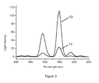
- The luminescence spectrum shown in
Figure 3 is generated through the bombardment of the cathode ray produced by the electron gun on the luminescent glass element of the example. Thecurve 11 inFigure 3 is the luminescence spectrum of the glass without the metallic silver film, while thecurve 13 is the luminescence spectrum of the luminescent glass element prepared in the example. It can be seen from the figure, compared with the luminescent glass without the metallic silver film, the luminescent integrated intensity from 400 nanometer to 650 nanometer of the luminescent glass element of the example has been enhanced by 5 folds since surface Plasmon effect is generated between the metallic silver layer 2 and the luminescent glass 1. The luminescent properties can thus be greatly improved. The luminescent spectrums of the following examples are the same as those of the example 1 and 2; each luminescent glass element has the similar luminescent intensity effect. Thus the mentioned aspects will not be repeated for concision hereinafter. - A green luminescent glass 25Na2O·15Y2O3·45SiO2·10Tb2O3 with a size of 1×1cm2 and a polished surface prepared through the above-mentioned preparing method is chosen to be a body. A metallic gold film with a thickness of 0.5 nanometer is deposited on the surface of the body by the usage of a magnetron sputtering device. Then the body with the metallic gold film is placed in an environment with a vacuum degree less than 1×10⁻³ Pa and annealed at 200°C for 1 h. After that, the luminescent glass element of the present example is obtained after cooling to room temperature.
- A green luminescent glass 27Na2O·0.01Y2O3·70SiO2·15Tb2O3 with a size of 1×1cm2 and a polished surface prepared through the above-mentioned preparing method is chosen to be a body. A metallic aluminum film with a thickness of 200 nanometer is deposited on the surface of the body by the usage of a magnetron sputtering device. Then the body with the metallic aluminum film is placed in an environment with a vacuum degree less than 1×10⁻³ Pa and annealed at 500°C for 5 h. After that, the luminescent glass element of the present example is obtained after cooling to room temperature.
- A green luminescent glass 32Na2O·1.5Y2O3·65SiO2·12Tb2O3 with a size of 1×1cm2 and a polished surface prepared through the above-mentioned preparing method is chosen to be a body. A metallic magnesium film with a thickness of 100 nanometer is evaporated on the surface of the body by the usage of an electron beam evaporation device. Then the body with the metallic magnesium film is placed in an environment with a vacuum degree less than 1×10⁻³ Pa and annealed at 650°C for 5 minutes. After that, the luminescent glass element of the present example is obtained after cooling to room temperature.
- A green luminescent glass 35Na2O·0.5Y2O3·50SiO2·13Tb2O3 with a size of 1×1cm2 and a polished surface prepared through the above-mentioned preparing method is chosen to be a body. A metallic palladium film with a thickness of 1 nanometer is evaporated on the surface of the body by the usage of an electron beam evaporation device. Then the body with the metallic palladium film is placed in an environment with a vacuum degree less than 1×10⁻³ Pa and annealed at 100°C for 3h. After that, the luminescent glass element of the present example is obtained after cooling to room temperature.
- A green luminescent glass 38Na2O·12Y2O3·43SiO2·0.5Tb2O3 with a size of 1×1cm2 and a polished surface prepared through the above-mentioned preparing method is chosen to be a body. A metallic platinum film with a thickness of 5 nanometer is evaporated on the surface of the body by the usage of an electron beam evaporation device. Then the body with the metallic platinum film is placed in an environment with a vacuum degree less than 1×10⁻³ Pa and annealed at 450°C for 15 minutes. After that, the luminescent glass element of the present example is obtained after cooling to room temperature.
- A green luminescent glass 28Na2O·10Y2O3·68SiO2·2Tb2O3 with a size of 1×1cm2 and a polished surface prepared through the above-mentioned preparing method is chosen to be a body. A metallic iron film with a thickness of 20 nanometer is evaporated on the surface of the body by the usage of an electron beam evaporation device. Then the body with the metallic iron film is placed in an environment with a vacuum degree less than 1×10⁻³ Pa and annealed at 50°C for 5h. After that, the luminescent glass element of the present example is obtained after cooling to room temperature.
- A green luminescent glass 35K2O·8Y2O3·55SiO2·0.01Tb2O3 with a size of 1×1cm2 and a polished surface prepared through the above-mentioned preparing method is chosen to be a body. A metallic titanium film with a thickness of 10 nanometer is evaporated on the surface of the body by the usage of an electron beam evaporation device. Then the body with the metallic titanium film is placed in an environment with a vacuum degree less than 1×10⁻³ Pa and annealed at 150°C for 2h. After that, the luminescent glass element of the present example is obtained after cooling to room temperature.
- A green luminescent glass 40K2O·5Y2O3·40SiO2·9Tb2O3 with a size of 1×1cm2 and a polished surface prepared through the above-mentioned preparing method is chosen to be a body. A metallic copper film with a thickness of 50 nanometer is evaporated on the surface of the body by the usage of an electron beam evaporation device. Then the body with the metallic copper film is placed in an environment with a vacuum degree less than 1×10⁻³ Pa and annealed at 200°C for 2.5h. After that, the luminescent glass element of the present example is obtained after cooling to room temperature.
- A green luminescent glass 36K2O·8Y2O3·58SiO2·0.8Tb2O3 with a size of 1×1cm2 and a polished surface prepared through the above-mentioned preparing method is chosen to be a body. A metallic zinc film with a thickness of 150 nanometer is evaporated on the surface of the body by the usage of an electron beam evaporation device. Then the body with the metallic zinc film is placed in an environment with a vacuum degree less than 1×10⁻³ Pa and annealed at 350°C for 0.5h. After that, the luminescent glass element of the present example is obtained after cooling to room temperature.
- A green luminescent glass 29K2O·11Y2O3·50SiO2·1.5Tb2O3 with a size of 1×1cm2 and a polished surface prepared through the above-mentioned preparing method is chosen to be a body. A metallic chromium film with a thickness of 120 nanometer is evaporated on the surface of the body by the usage of an electron beam evaporation device. Then the body with the metallic chromium film is placed in an environment with a vacuum degree less than 1×10⁻³ Pa and annealed at 250°C for 2h. After that, the luminescent glass element of the present example is obtained after cooling to room temperature.
- A green luminescent glass 3K2O·7Y2O3·58SiO2·7Tb2O3 with a size of 1×1cm2 and a polished surface prepared through the above-mentioned preparing method is chosen to be a body. A metallic nickel film with a thickness of 40 nanometer is evaporated on the surface of the body by the usage of an electron beam evaporation device. Then the body with the metallic nickel film is placed in an environment with a vacuum degree less than 1×10⁻³ Pa and annealed at 80°C for 4h. After that, the luminescent glass element of the present example is obtained after cooling to room temperature.
- A green luminescent glass 26K2O·4Y2O3·69SiO2·9.5Tb2O3 with a size of 1×1cm2 and a polished surface prepared through the above-mentioned preparing method is chosen to be a body. A metallic cobalt film with a thickness of 180 nanometer is evaporated on the surface of the body by the usage of an electron beam evaporation device. Then the body with the metallic cobalt film is placed in an environment with a vacuum degree less than 1×10⁻³ Pa and annealed at 400°C for 1 h. After that, the luminescent glass element of the present example is obtained after cooling to room temperature.
- A green luminescent glass 45K2O·8Y2O3·48SiO2·1.5Tb2O3 with a size of 1×1cm2 and a polished surface prepared through the above-mentioned preparing method is chosen to be a body. A metallic silver-aluminum film with a thickness of 8 nanometer is evaporated on the surface of the body by the usage of an electron beam evaporation device, wherein the weight fractions of the silver and the aluminum in the metal film are respectively 80% and 20%. Then the body with the metallic silver-aluminum film is placed in an environment with a vacuum degree less than 1×10⁻³ Pa and annealed at 380°C for 2.5h. After that, the luminescent glass element of the present example is obtained after cooling to room temperature.
- A green luminescent glass 36K2O·16Y2O3·52SiO2·4Tb2O3 with a size of 1×1cm2 and a polished surface prepared through the above-mentioned preparing method is chosen to be a body. A metallic silver-aluminum film with a thickness of 15 nanometer is evaporated on the surface of the body by the usage of an electron beam evaporation device, wherein the weight fractions of the silver and the aluminum in the metal film are respectively 90% and 10%. Then the body with the metallic silver-aluminum film is placed in an environment with a vacuum degree less than 1×10⁻³ Pa and annealed at 180°C for 3.5h. After that, the luminescent glass element of the present example is obtained after cooling to room temperature.
- A green luminescent glass 55K2O·3Y2O3·62SiO2·7Tb2O3 with a size of 1×cm2 and a polished surface prepared through the above-mentioned preparing method is chosen to be a body. A metallic gold-aluminum film with a thickness of 7 nanometer is evaporated on the surface of the body by the usage of an electron beam evaporation device, wherein the weight fractions of the gold and the aluminum in the metal film are respectively 80% and 20%. Then the body with the metallic gold-aluminum film is placed in an environment with a vacuum degree less than 1×10⁻³ Pa and annealed at 270°C for 1.5h. After that, the luminescent glass element of the present example is obtained after cooling to room temperature.
- A green luminescent glass 58K2O·6Y2O3·35SiO2·9Tb2O3 with a size of 1×1cm2 and a polished surface prepared through the above-mentioned preparing method is chosen to be a body. A metallic gold-aluminum film with a thickness of 80 nanometer is evaporated on the surface of the body by the usage of an electron beam evaporation device, wherein the weight fractions of the gold and the aluminum in the metal film are respectively 90% and 10%. Then the body with the metallic gold-aluminum film is placed in an environment with a vacuum degree less than 1×10⁻³ Pa and annealed at 600°C for 4.5h. After that, the luminescent glass element of the present example is obtained after cooling to room temperature.
Claims (12)
- A method for raising luminous efficiency of a field emissive luminescent material, comprising following steps: taking a luminescent glass as a body; forming a nonperiodic metal film having metal micro-nano structures on a surface of the luminescent glass body to prepare a luminescent glass element; eradiating a cathode ray to the luminescent glass element, wherein the cathode ray penetrating the metal film and exciting the luminescent glass body to luminesce; wherein, a chemical general formula of the luminescent glass body is aM2O·bY2O3·cSiO2·dTb2O3, wherein M is an alkali metal, and a, b, c and d are molar fractions, ranges of which are respectively as follows: the range of a is 25∼60, the range of b is 0.01∼15, the range of c is 40∼70 and the range of d is 0.01∼15.
- A luminescent glass element used by a method for raising luminous efficiency of a field emissive luminescent material, comprising a luminescent glass body, wherein a metal film having metal microstructure is arranged on a surface of the luminescent glass body; the luminescent glass body comprises composite oxides with a following chemical general formula:
aM2O·bY2O3·cSiO2d·Tb2O3,
wherein M is an alkali metal, and a, b, c and d are molar fractions, ranges of which are respectively as follows: the range of a is 25∼60, the range of b is 0.01∼15, the range of c is 40∼70 and the range of d is 0.01∼15. - The luminescent glass element according to claim 2, wherein the alkali metal is at least one selected from a group of Na, K and Li.
- The luminescent glass element according to claim 2, wherein the metal of the metal film is at least one selected from a group of gold, silver, aluminum, copper, titanium, iron, nickel, cobalt, chromium, platinum, palladium, magnesium and zinc.
- The luminescent glass element according to claim 4, wherein the metal of the metal film is at least one selected from a group of gold, silver and aluminum.
- The luminescent glass element according to claim 2, wherein a thickness of the metal film is 0.5 nanometer ∼200 nanometer.
- The luminescent glass element according to claim 6, wherein the thickness of the metal film is 1 nanometer ∼ 100 nanometer.
- A preparing method for a luminescent glass element, comprising following steps:preparing a luminescent glass body which comprising composite oxides with a following chemical general formula: aM2O·bY2O3·cSiO2·dTb2O3, wherein M is an alkali metal, and a, b, c and d are molar fractions, ranges of which are respectively as follows: the range of a is 25∼60, the range of b is 0.01∼15, the range of c is 40∼70 and the range of d is 0.01∼15;forming a metal film on a surface of the luminescent glass body; andannealing the luminescent glass body and the metal film in vacuum so that the metal film forms metal microstructures, and then obtaining the desired luminescent glass element after cooling.
- The preparing method for a luminescent glass element according to claim 8, wherein preparing steps for the luminescent glass body are as follows: taking alkali metal salt, SiO2, Y2O3 and Tb4O7 in their respective corresponding molar fraction as raw materials; melting the raw materials at 1200°C∼1500°C; placing a melted product in a reducing atmosphere after cooling; then annealing a reduced product at 600°C∼1100°C to obtain the luminescent glass body.
- The preparing method for a luminescent glass element according to claim 8, wherein the metal film is formed through sputtering or evaporating a metal onto the surface of the luminescent glass body.
- The preparing method for a luminescent glass element according to claim 8, wherein, the annealing in vacuum is proceeded at 50°C∼650°C for 5 minutes∼5 hours.
- The preparing method for a luminescent glass element according to claim 11, wherein, the annealing in vacuum is proceeded at 100°C∼500°C for 15 minutes∼3 hours.
Applications Claiming Priority (1)
| Application Number | Priority Date | Filing Date | Title |
|---|---|---|---|
| PCT/CN2009/072403 WO2010148553A1 (en) | 2009-06-23 | 2009-06-23 | Method for raising luminous efficiency of field emissive luminescent material, luminescent glass element and the preparing method thereof |
Publications (2)
| Publication Number | Publication Date |
|---|---|
| EP2447982A1 true EP2447982A1 (en) | 2012-05-02 |
| EP2447982A4 EP2447982A4 (en) | 2016-11-30 |
Family
ID=43385863
Family Applications (1)
| Application Number | Title | Priority Date | Filing Date |
|---|---|---|---|
| EP09846353.2A Withdrawn EP2447982A4 (en) | 2009-06-23 | 2009-06-23 | Method for raising luminous efficiency of field emissive luminescent material, luminescent glass element and the preparing method thereof |
Country Status (5)
| Country | Link |
|---|---|
| US (1) | US9087685B2 (en) |
| EP (1) | EP2447982A4 (en) |
| JP (1) | JP5435517B2 (en) |
| CN (1) | CN102422384B (en) |
| WO (1) | WO2010148553A1 (en) |
Cited By (1)
| Publication number | Priority date | Publication date | Assignee | Title |
|---|---|---|---|---|
| EP2489644A1 (en) * | 2009-08-26 | 2012-08-22 | Ocean's King Lighting Science&Technology Co., Ltd. | Luminescent element, producing method thereof and luminescence method using the same |
Families Citing this family (6)
| Publication number | Priority date | Publication date | Assignee | Title |
|---|---|---|---|---|
| EP2447337A4 (en) * | 2009-06-26 | 2014-12-24 | Oceans King Lighting Science | Luminescent glass element, manufacturing method and luminescence method thereof |
| CN103426703A (en) * | 2012-05-17 | 2013-12-04 | 海洋王照明科技股份有限公司 | Light-emitting element for field emission device |
| CN103426716A (en) * | 2012-05-17 | 2013-12-04 | 海洋王照明科技股份有限公司 | Field emission light source device |
| CN105742167A (en) * | 2014-12-08 | 2016-07-06 | 天津恒电空间电源有限公司 | Preparation method of multilayer metal electrode capable of being firmly combined with glass |
| WO2018163759A1 (en) * | 2017-03-09 | 2018-09-13 | 日本電気硝子株式会社 | Glass material and method for manufacturing same |
| JP6993612B2 (en) * | 2017-03-09 | 2022-01-13 | 日本電気硝子株式会社 | Glass material and its manufacturing method |
Family Cites Families (26)
| Publication number | Priority date | Publication date | Assignee | Title |
|---|---|---|---|---|
| US3523091A (en) * | 1967-10-27 | 1970-08-04 | Westinghouse Electric Corp | Lanthanum,yttrium silicate phosphors |
| US3654172A (en) * | 1970-03-26 | 1972-04-04 | Corning Glass Works | Terbium activated radioluminescent silicate glasses |
| JPS6010065B2 (en) * | 1981-06-16 | 1985-03-14 | 株式会社東芝 | green emitting phosphor |
| JPH0747732B2 (en) * | 1987-12-05 | 1995-05-24 | 日亜化学工業株式会社 | Slow electron beam excited phosphor |
| US5391320A (en) * | 1989-08-28 | 1995-02-21 | Lockheed Missiles & Space Company, Inc. | Terbium activated silicate luminescent glasses |
| JPH06157073A (en) * | 1992-11-24 | 1994-06-03 | Mitsuboshi Belting Ltd | Production of semiconductor element using metal fine particle-dispersed glass |
| JPH09189662A (en) * | 1996-01-08 | 1997-07-22 | Hitachi Ltd | Electrochemical light emitting cell and electrochemical emission spectrometer |
| DE19750794A1 (en) * | 1997-11-10 | 1999-06-17 | Ivoclar Ag | Process for the preparation of shaped translucent lithium disilicate glass-ceramic products |
| JP4421001B2 (en) * | 1998-04-01 | 2010-02-24 | 株式会社住田光学ガラス | Oxide glass with long afterglow and stimulated emission |
| JP3834670B2 (en) * | 1998-05-13 | 2006-10-18 | 株式会社住田光学ガラス | Oxide glass with long afterglow and stimulated emission |
| JP2000243271A (en) * | 1999-02-19 | 2000-09-08 | Canon Inc | Metal film forming method |
| JP2001266768A (en) * | 2000-03-15 | 2001-09-28 | Matsushita Electric Works Ltd | Surface emission plate, method of producing plane luminescent plate, flat crt display, and field emission display |
| US6531074B2 (en) * | 2000-01-14 | 2003-03-11 | Osram Sylvania Inc. | Luminescent nanophase binder systems for UV and VUV applications |
| KR100786854B1 (en) * | 2001-02-06 | 2007-12-20 | 삼성에스디아이 주식회사 | A filter for a display, a method for preparing the same and a display comprising the same |
| JP2003031150A (en) * | 2001-07-13 | 2003-01-31 | Toshiba Corp | Fluorescent plane with metal back, metal back forming transcription film, and image display device |
| US7758774B2 (en) * | 2002-11-29 | 2010-07-20 | Japan Science And Technology Agency | Luminescent glass |
| JP2006083045A (en) * | 2004-09-17 | 2006-03-30 | Hitachi Ltd | Glass member |
| CN100433235C (en) * | 2005-12-20 | 2008-11-12 | 陕西科技大学 | Field emission display device in separated structure |
| JP4347343B2 (en) * | 2006-05-09 | 2009-10-21 | 富士重工業株式会社 | Light emitting device |
| CN101442089B (en) * | 2007-11-21 | 2010-06-02 | 中国科学院半导体研究所 | Method for reinforcing zinc oxide film blue light emission |
| WO2010108317A1 (en) * | 2009-03-25 | 2010-09-30 | 海洋王照明科技股份有限公司 | Green light-emitting glass and method of preparing the same |
| WO2010148566A1 (en) * | 2009-06-26 | 2010-12-29 | 海洋王照明科技股份有限公司 | Luminescent glass element, the preparing method thereof and the method for luminescence using the element |
| EP2472562B1 (en) * | 2009-08-26 | 2016-08-10 | Ocean's King Lighting Science&Technology Co., Ltd. | Luminescent element, producing method thereof and luminescence method using the same |
| WO2011022879A1 (en) * | 2009-08-26 | 2011-03-03 | 海洋王照明科技股份有限公司 | Luminescent element, producing method thereof and luminescence method using the same |
| WO2011022880A1 (en) * | 2009-08-26 | 2011-03-03 | 海洋王照明科技股份有限公司 | Luminescent element, producing method thereof and luminescence method using the same |
| US9096792B2 (en) * | 2009-08-26 | 2015-08-04 | Ocean's King Lighting Science & Technology Co., Ltd. | Luminescent element including nitride, preparation method thereof and luminescence method |
-
2009
- 2009-06-23 WO PCT/CN2009/072403 patent/WO2010148553A1/en active Application Filing
- 2009-06-23 CN CN200980159142XA patent/CN102422384B/en active Active
- 2009-06-23 US US13/376,385 patent/US9087685B2/en not_active Expired - Fee Related
- 2009-06-23 JP JP2012516471A patent/JP5435517B2/en active Active
- 2009-06-23 EP EP09846353.2A patent/EP2447982A4/en not_active Withdrawn
Non-Patent Citations (1)
| Title |
|---|
| See references of WO2010148553A1 * |
Cited By (3)
| Publication number | Priority date | Publication date | Assignee | Title |
|---|---|---|---|---|
| EP2489644A1 (en) * | 2009-08-26 | 2012-08-22 | Ocean's King Lighting Science&Technology Co., Ltd. | Luminescent element, producing method thereof and luminescence method using the same |
| EP2489644A4 (en) * | 2009-08-26 | 2014-02-26 | Oceans King Lighting Science | Luminescent element, producing method thereof and luminescence method using the same |
| US9000667B2 (en) | 2009-08-26 | 2015-04-07 | Ocean's King Lighting Science & Technology Co., Ltd. | Luminescent element, preparation method thereof and luminescence method |
Also Published As
| Publication number | Publication date |
|---|---|
| WO2010148553A1 (en) | 2010-12-29 |
| EP2447982A4 (en) | 2016-11-30 |
| US20120077025A1 (en) | 2012-03-29 |
| CN102422384B (en) | 2013-09-18 |
| US9087685B2 (en) | 2015-07-21 |
| CN102422384A (en) | 2012-04-18 |
| JP5435517B2 (en) | 2014-03-05 |
| JP2012530665A (en) | 2012-12-06 |
Similar Documents
| Publication | Publication Date | Title |
|---|---|---|
| US9087685B2 (en) | Method for raising luminous efficiency of field emissive luminescent material, luminescent glass element and the preparing method thereof | |
| US8217369B2 (en) | Luminescent glass element, producing method thereof and luminescing method thereof | |
| US8216671B2 (en) | Luminescent glass element, producing method thereof and luminescing method thereof | |
| WO2011022878A1 (en) | Luminescent element, producing method thereof and luminescence method using the same | |
| JP5350546B2 (en) | LIGHT EMITTING DEVICE, ITS MANUFACTURING METHOD, AND LIGHT EMITTING METHOD USING THE SAME | |
| WO2011022876A1 (en) | Light emitting element, manufacturing method and light emitting method thereof | |
| US8217370B2 (en) | Luminescent glass element, producing method thereof and luminescing method thereof | |
| JP5599885B2 (en) | LIGHT EMITTING DEVICE, METHOD FOR PRODUCING THEM, AND LIGHT EMITTING METHOD | |
| US8115181B2 (en) | Luminescent glass element, producing method thereof and luminescing method thereof | |
| JP5612687B2 (en) | LIGHT EMITTING DEVICE, METHOD FOR PRODUCING THEM, AND LIGHT EMITTING METHOD | |
| US8415017B2 (en) | Luminescent glass element, producing method thereof and luminescing method thereof | |
| CN102439113B (en) | Luminescent glass element, manufacturing method and luminescence method thereof |
Legal Events
| Date | Code | Title | Description |
|---|---|---|---|
| PUAI | Public reference made under article 153(3) epc to a published international application that has entered the european phase |
Free format text: ORIGINAL CODE: 0009012 |
|
| 17P | Request for examination filed |
Effective date: 20111229 |
|
| AK | Designated contracting states |
Kind code of ref document: A1 Designated state(s): AT BE BG CH CY CZ DE DK EE ES FI FR GB GR HR HU IE IS IT LI LT LU LV MC MK MT NL NO PL PT RO SE SI SK TR |
|
| DAX | Request for extension of the european patent (deleted) | ||
| RA4 | Supplementary search report drawn up and despatched (corrected) |
Effective date: 20161103 |
|
| RIC1 | Information provided on ipc code assigned before grant |
Ipc: C09K 11/77 20060101ALI20161027BHEP Ipc: C03C 3/095 20060101ALI20161027BHEP Ipc: C03C 17/06 20060101ALI20161027BHEP Ipc: C03C 4/12 20060101ALI20161027BHEP Ipc: H01J 63/06 20060101AFI20161027BHEP Ipc: C03C 3/062 20060101ALI20161027BHEP |
|
| STAA | Information on the status of an ep patent application or granted ep patent |
Free format text: STATUS: REQUEST FOR EXAMINATION WAS MADE |
|
| STAA | Information on the status of an ep patent application or granted ep patent |
Free format text: STATUS: THE APPLICATION IS DEEMED TO BE WITHDRAWN |
|
| 18D | Application deemed to be withdrawn |
Effective date: 20170603 |