EP2437795B1 - Decontamination of enclosed space using gaseous chlorine dioxide - Google Patents
Decontamination of enclosed space using gaseous chlorine dioxide Download PDFInfo
- Publication number
- EP2437795B1 EP2437795B1 EP10783758.5A EP10783758A EP2437795B1 EP 2437795 B1 EP2437795 B1 EP 2437795B1 EP 10783758 A EP10783758 A EP 10783758A EP 2437795 B1 EP2437795 B1 EP 2437795B1
- Authority
- EP
- European Patent Office
- Prior art keywords
- chlorine dioxide
- emitter
- gas
- air
- concentration
- Prior art date
- Legal status (The legal status is an assumption and is not a legal conclusion. Google has not performed a legal analysis and makes no representation as to the accuracy of the status listed.)
- Not-in-force
Links
- OSVXSBDYLRYLIG-UHFFFAOYSA-N dioxidochlorine(.) Chemical compound O=Cl=O OSVXSBDYLRYLIG-UHFFFAOYSA-N 0.000 title claims description 483
- 239000004155 Chlorine dioxide Substances 0.000 title claims description 242
- 235000019398 chlorine dioxide Nutrition 0.000 title claims description 181
- 238000005202 decontamination Methods 0.000 title description 10
- 230000003588 decontaminative effect Effects 0.000 title description 9
- 238000000034 method Methods 0.000 claims description 57
- 229910052751 metal Inorganic materials 0.000 claims description 17
- 239000002184 metal Substances 0.000 claims description 17
- RYGMFSIKBFXOCR-UHFFFAOYSA-N Copper Chemical compound [Cu] RYGMFSIKBFXOCR-UHFFFAOYSA-N 0.000 claims description 12
- 229910052802 copper Inorganic materials 0.000 claims description 12
- 239000010949 copper Substances 0.000 claims description 12
- 239000000356 contaminant Substances 0.000 claims description 11
- 241000894006 Bacteria Species 0.000 claims description 10
- 241000193410 Bacillus atrophaeus Species 0.000 claims description 9
- 150000002739 metals Chemical class 0.000 claims description 8
- 229910000831 Steel Inorganic materials 0.000 claims description 6
- 239000010959 steel Substances 0.000 claims description 6
- XEEYBQQBJWHFJM-UHFFFAOYSA-N Iron Chemical compound [Fe] XEEYBQQBJWHFJM-UHFFFAOYSA-N 0.000 claims description 4
- 241000239223 Arachnida Species 0.000 claims description 3
- 241000238631 Hexapoda Species 0.000 claims description 3
- QAOWNCQODCNURD-UHFFFAOYSA-L Sulfate Chemical compound [O-]S([O-])(=O)=O QAOWNCQODCNURD-UHFFFAOYSA-L 0.000 claims description 3
- 229910052782 aluminium Inorganic materials 0.000 claims description 3
- XAGFODPZIPBFFR-UHFFFAOYSA-N aluminium Chemical compound [Al] XAGFODPZIPBFFR-UHFFFAOYSA-N 0.000 claims description 3
- VYZAMTAEIAYCRO-UHFFFAOYSA-N Chromium Chemical compound [Cr] VYZAMTAEIAYCRO-UHFFFAOYSA-N 0.000 claims description 2
- 241000270322 Lepidosauria Species 0.000 claims description 2
- 231100000678 Mycotoxin Toxicity 0.000 claims description 2
- 239000013566 allergen Substances 0.000 claims description 2
- 229910052804 chromium Inorganic materials 0.000 claims description 2
- 239000011651 chromium Substances 0.000 claims description 2
- 229910052742 iron Inorganic materials 0.000 claims description 2
- 239000011133 lead Substances 0.000 claims description 2
- 239000002636 mycotoxin Substances 0.000 claims description 2
- 239000007789 gas Substances 0.000 description 105
- 238000003958 fumigation Methods 0.000 description 67
- XLYOFNOQVPJJNP-UHFFFAOYSA-N water Chemical compound O XLYOFNOQVPJJNP-UHFFFAOYSA-N 0.000 description 49
- 238000012360 testing method Methods 0.000 description 40
- 239000000243 solution Substances 0.000 description 39
- 210000004215 spore Anatomy 0.000 description 32
- 238000005260 corrosion Methods 0.000 description 31
- 230000007797 corrosion Effects 0.000 description 31
- 239000000463 material Substances 0.000 description 23
- 230000008569 process Effects 0.000 description 23
- 238000005067 remediation Methods 0.000 description 22
- 239000012071 phase Substances 0.000 description 17
- 230000012010 growth Effects 0.000 description 14
- 239000000090 biomarker Substances 0.000 description 13
- 238000012544 monitoring process Methods 0.000 description 13
- UPMXNNIRAGDFEH-UHFFFAOYSA-N 3,5-dibromo-4-hydroxybenzonitrile Chemical compound OC1=C(Br)C=C(C#N)C=C1Br UPMXNNIRAGDFEH-UHFFFAOYSA-N 0.000 description 11
- 241000193738 Bacillus anthracis Species 0.000 description 10
- 230000035515 penetration Effects 0.000 description 10
- 239000000523 sample Substances 0.000 description 10
- 235000019645 odor Nutrition 0.000 description 9
- 239000003795 chemical substances by application Substances 0.000 description 8
- 239000007788 liquid Substances 0.000 description 8
- 239000013641 positive control Substances 0.000 description 8
- 238000005070 sampling Methods 0.000 description 8
- 238000005201 scrubbing Methods 0.000 description 8
- 229910001209 Low-carbon steel Inorganic materials 0.000 description 7
- 230000000694 effects Effects 0.000 description 7
- 230000007613 environmental effect Effects 0.000 description 7
- 230000000813 microbial effect Effects 0.000 description 7
- QGJOPFRUJISHPQ-UHFFFAOYSA-N Carbon disulfide Chemical compound S=C=S QGJOPFRUJISHPQ-UHFFFAOYSA-N 0.000 description 6
- 238000004061 bleaching Methods 0.000 description 6
- 238000005516 engineering process Methods 0.000 description 6
- 238000005057 refrigeration Methods 0.000 description 6
- 239000000126 substance Substances 0.000 description 6
- 230000000007 visual effect Effects 0.000 description 6
- 230000001580 bacterial effect Effects 0.000 description 5
- 230000008030 elimination Effects 0.000 description 5
- 238000003379 elimination reaction Methods 0.000 description 5
- 239000012530 fluid Substances 0.000 description 5
- 229920001903 high density polyethylene Polymers 0.000 description 5
- 239000004700 high-density polyethylene Substances 0.000 description 5
- 239000000047 product Substances 0.000 description 5
- 238000004659 sterilization and disinfection Methods 0.000 description 5
- 230000003113 alkalizing effect Effects 0.000 description 4
- 238000004458 analytical method Methods 0.000 description 4
- JJWKPURADFRFRB-UHFFFAOYSA-N carbonyl sulfide Chemical compound O=C=S JJWKPURADFRFRB-UHFFFAOYSA-N 0.000 description 4
- 238000011109 contamination Methods 0.000 description 4
- 230000000382 dechlorinating effect Effects 0.000 description 4
- 239000002316 fumigant Substances 0.000 description 4
- 229910052602 gypsum Inorganic materials 0.000 description 4
- 239000010440 gypsum Substances 0.000 description 4
- 239000003595 mist Substances 0.000 description 4
- 239000000203 mixture Substances 0.000 description 4
- 230000003647 oxidation Effects 0.000 description 4
- 238000007254 oxidation reaction Methods 0.000 description 4
- 230000001590 oxidative effect Effects 0.000 description 4
- 239000007921 spray Substances 0.000 description 4
- 239000011593 sulfur Substances 0.000 description 4
- 229910052717 sulfur Inorganic materials 0.000 description 4
- OKTJSMMVPCPJKN-UHFFFAOYSA-N Carbon Chemical compound [C] OKTJSMMVPCPJKN-UHFFFAOYSA-N 0.000 description 3
- 230000036541 health Effects 0.000 description 3
- 238000010438 heat treatment Methods 0.000 description 3
- 230000005789 organism growth Effects 0.000 description 3
- NLKNQRATVPKPDG-UHFFFAOYSA-M potassium iodide Chemical compound [K+].[I-] NLKNQRATVPKPDG-UHFFFAOYSA-M 0.000 description 3
- 238000012545 processing Methods 0.000 description 3
- 230000001954 sterilising effect Effects 0.000 description 3
- 238000003860 storage Methods 0.000 description 3
- 239000000758 substrate Substances 0.000 description 3
- 239000008399 tap water Substances 0.000 description 3
- 235000020679 tap water Nutrition 0.000 description 3
- ASOKPJOREAFHNY-UHFFFAOYSA-N 1-Hydroxybenzotriazole Chemical compound C1=CC=C2N(O)N=NC2=C1 ASOKPJOREAFHNY-UHFFFAOYSA-N 0.000 description 2
- CIWBSHSKHKDKBQ-JLAZNSOCSA-N Ascorbic acid Chemical compound OC[C@H](O)[C@H]1OC(=O)C(O)=C1O CIWBSHSKHKDKBQ-JLAZNSOCSA-N 0.000 description 2
- KZBUYRJDOAKODT-UHFFFAOYSA-N Chlorine Chemical compound ClCl KZBUYRJDOAKODT-UHFFFAOYSA-N 0.000 description 2
- ZAMOUSCENKQFHK-UHFFFAOYSA-N Chlorine atom Chemical compound [Cl] ZAMOUSCENKQFHK-UHFFFAOYSA-N 0.000 description 2
- RWSOTUBLDIXVET-UHFFFAOYSA-N Dihydrogen sulfide Chemical compound S RWSOTUBLDIXVET-UHFFFAOYSA-N 0.000 description 2
- 229910001335 Galvanized steel Inorganic materials 0.000 description 2
- 229910000677 High-carbon steel Inorganic materials 0.000 description 2
- 241000257303 Hymenoptera Species 0.000 description 2
- 238000004378 air conditioning Methods 0.000 description 2
- 238000013459 approach Methods 0.000 description 2
- 229940065181 bacillus anthracis Drugs 0.000 description 2
- 210000004666 bacterial spore Anatomy 0.000 description 2
- 239000011449 brick Substances 0.000 description 2
- 239000004566 building material Substances 0.000 description 2
- 239000000460 chlorine Substances 0.000 description 2
- 229910052801 chlorine Inorganic materials 0.000 description 2
- 239000004567 concrete Substances 0.000 description 2
- 238000001816 cooling Methods 0.000 description 2
- 238000010586 diagram Methods 0.000 description 2
- 238000005553 drilling Methods 0.000 description 2
- -1 exposed Chemical class 0.000 description 2
- 239000008397 galvanized steel Substances 0.000 description 2
- 229910000037 hydrogen sulfide Inorganic materials 0.000 description 2
- 230000000415 inactivating effect Effects 0.000 description 2
- 238000003780 insertion Methods 0.000 description 2
- 230000037431 insertion Effects 0.000 description 2
- 239000002906 medical waste Substances 0.000 description 2
- 230000000116 mitigating effect Effects 0.000 description 2
- 239000002243 precursor Substances 0.000 description 2
- 238000002203 pretreatment Methods 0.000 description 2
- 238000003303 reheating Methods 0.000 description 2
- UKLNMMHNWFDKNT-UHFFFAOYSA-M sodium chlorite Chemical compound [Na+].[O-]Cl=O UKLNMMHNWFDKNT-UHFFFAOYSA-M 0.000 description 2
- 238000001228 spectrum Methods 0.000 description 2
- 238000009423 ventilation Methods 0.000 description 2
- 230000004580 weight loss Effects 0.000 description 2
- 239000002023 wood Substances 0.000 description 2
- BZSXEZOLBIJVQK-UHFFFAOYSA-N 2-methylsulfonylbenzoic acid Chemical compound CS(=O)(=O)C1=CC=CC=C1C(O)=O BZSXEZOLBIJVQK-UHFFFAOYSA-N 0.000 description 1
- 241000239290 Araneae Species 0.000 description 1
- VEXZGXHMUGYJMC-UHFFFAOYSA-M Chloride anion Chemical compound [Cl-] VEXZGXHMUGYJMC-UHFFFAOYSA-M 0.000 description 1
- 229910001208 Crucible steel Inorganic materials 0.000 description 1
- 206010011906 Death Diseases 0.000 description 1
- 241000255925 Diptera Species 0.000 description 1
- 241000270290 Gekkota Species 0.000 description 1
- 241000256602 Isoptera Species 0.000 description 1
- 239000004698 Polyethylene Substances 0.000 description 1
- 239000004775 Tyvek Substances 0.000 description 1
- 229920000690 Tyvek Polymers 0.000 description 1
- 239000002253 acid Substances 0.000 description 1
- 239000003929 acidic solution Substances 0.000 description 1
- 230000002411 adverse Effects 0.000 description 1
- 230000002009 allergenic effect Effects 0.000 description 1
- OPIARDKIWVCIRZ-UHFFFAOYSA-N aluminum;copper Chemical compound [Al+3].[Cu+2] OPIARDKIWVCIRZ-UHFFFAOYSA-N 0.000 description 1
- 239000007864 aqueous solution Substances 0.000 description 1
- 235000010323 ascorbic acid Nutrition 0.000 description 1
- 229960005070 ascorbic acid Drugs 0.000 description 1
- 239000011668 ascorbic acid Substances 0.000 description 1
- 230000004888 barrier function Effects 0.000 description 1
- 238000007664 blowing Methods 0.000 description 1
- 230000005587 bubbling Effects 0.000 description 1
- 229910052799 carbon Inorganic materials 0.000 description 1
- 230000015556 catabolic process Effects 0.000 description 1
- 239000001913 cellulose Substances 0.000 description 1
- 229920002678 cellulose Polymers 0.000 description 1
- 239000000919 ceramic Substances 0.000 description 1
- 239000013043 chemical agent Substances 0.000 description 1
- QBWCMBCROVPCKQ-UHFFFAOYSA-N chlorous acid Chemical class OCl=O QBWCMBCROVPCKQ-UHFFFAOYSA-N 0.000 description 1
- 239000003818 cinder Substances 0.000 description 1
- 150000001875 compounds Chemical class 0.000 description 1
- 238000010276 construction Methods 0.000 description 1
- 238000000354 decomposition reaction Methods 0.000 description 1
- 238000006731 degradation reaction Methods 0.000 description 1
- 238000007791 dehumidification Methods 0.000 description 1
- 238000013461 design Methods 0.000 description 1
- 239000000645 desinfectant Substances 0.000 description 1
- 238000001514 detection method Methods 0.000 description 1
- 238000002845 discoloration Methods 0.000 description 1
- 238000011156 evaluation Methods 0.000 description 1
- 238000002474 experimental method Methods 0.000 description 1
- 238000004880 explosion Methods 0.000 description 1
- 238000011010 flushing procedure Methods 0.000 description 1
- 239000006260 foam Substances 0.000 description 1
- 239000013505 freshwater Substances 0.000 description 1
- 239000001963 growth medium Substances 0.000 description 1
- 238000005286 illumination Methods 0.000 description 1
- 239000012535 impurity Substances 0.000 description 1
- 238000011065 in-situ storage Methods 0.000 description 1
- 230000002779 inactivation Effects 0.000 description 1
- 238000002347 injection Methods 0.000 description 1
- 239000007924 injection Substances 0.000 description 1
- 230000003993 interaction Effects 0.000 description 1
- JEIPFZHSYJVQDO-UHFFFAOYSA-N iron(III) oxide Inorganic materials O=[Fe]O[Fe]=O JEIPFZHSYJVQDO-UHFFFAOYSA-N 0.000 description 1
- 238000004519 manufacturing process Methods 0.000 description 1
- 238000005259 measurement Methods 0.000 description 1
- QSHDDOUJBYECFT-UHFFFAOYSA-N mercury Chemical compound [Hg] QSHDDOUJBYECFT-UHFFFAOYSA-N 0.000 description 1
- 229910052753 mercury Inorganic materials 0.000 description 1
- 229910052976 metal sulfide Inorganic materials 0.000 description 1
- 230000001473 noxious effect Effects 0.000 description 1
- 239000003921 oil Substances 0.000 description 1
- 239000007800 oxidant agent Substances 0.000 description 1
- 230000000737 periodic effect Effects 0.000 description 1
- 239000012466 permeate Substances 0.000 description 1
- 229920000573 polyethylene Polymers 0.000 description 1
- 238000005086 pumping Methods 0.000 description 1
- 238000010926 purge Methods 0.000 description 1
- 238000003908 quality control method Methods 0.000 description 1
- 230000000246 remedial effect Effects 0.000 description 1
- 238000012827 research and development Methods 0.000 description 1
- 239000012266 salt solution Substances 0.000 description 1
- 239000000565 sealant Substances 0.000 description 1
- 229960002218 sodium chlorite Drugs 0.000 description 1
- AKHNMLFCWUSKQB-UHFFFAOYSA-L sodium thiosulfate Chemical compound [Na+].[Na+].[O-]S([O-])(=O)=S AKHNMLFCWUSKQB-UHFFFAOYSA-L 0.000 description 1
- 235000019345 sodium thiosulphate Nutrition 0.000 description 1
- 230000005002 sporogony Effects 0.000 description 1
- 239000010935 stainless steel Substances 0.000 description 1
- 229910001220 stainless steel Inorganic materials 0.000 description 1
- 239000003206 sterilizing agent Substances 0.000 description 1
- 230000000638 stimulation Effects 0.000 description 1
- 239000004575 stone Substances 0.000 description 1
- 150000003464 sulfur compounds Chemical class 0.000 description 1
- 230000009182 swimming Effects 0.000 description 1
- 238000010998 test method Methods 0.000 description 1
- 238000004448 titration Methods 0.000 description 1
- 239000001974 tryptic soy broth Substances 0.000 description 1
- 108010050327 trypticase-soy broth Proteins 0.000 description 1
- 239000012808 vapor phase Substances 0.000 description 1
- 230000035899 viability Effects 0.000 description 1
- 239000002918 waste heat Substances 0.000 description 1
- 239000002699 waste material Substances 0.000 description 1
- 238000005200 wet scrubbing Methods 0.000 description 1
- 239000002759 woven fabric Substances 0.000 description 1
Images


Classifications
-
- A—HUMAN NECESSITIES
- A61—MEDICAL OR VETERINARY SCIENCE; HYGIENE
- A61L—METHODS OR APPARATUS FOR STERILISING MATERIALS OR OBJECTS IN GENERAL; DISINFECTION, STERILISATION OR DEODORISATION OF AIR; CHEMICAL ASPECTS OF BANDAGES, DRESSINGS, ABSORBENT PADS OR SURGICAL ARTICLES; MATERIALS FOR BANDAGES, DRESSINGS, ABSORBENT PADS OR SURGICAL ARTICLES
- A61L9/00—Disinfection, sterilisation or deodorisation of air
- A61L9/015—Disinfection, sterilisation or deodorisation of air using gaseous or vaporous substances, e.g. ozone
- A61L9/04—Disinfection, sterilisation or deodorisation of air using gaseous or vaporous substances, e.g. ozone using substances evaporated in the air without heating
- A61L9/12—Apparatus, e.g. holders, therefor
- A61L9/122—Apparatus, e.g. holders, therefor comprising a fan
-
- A—HUMAN NECESSITIES
- A61—MEDICAL OR VETERINARY SCIENCE; HYGIENE
- A61L—METHODS OR APPARATUS FOR STERILISING MATERIALS OR OBJECTS IN GENERAL; DISINFECTION, STERILISATION OR DEODORISATION OF AIR; CHEMICAL ASPECTS OF BANDAGES, DRESSINGS, ABSORBENT PADS OR SURGICAL ARTICLES; MATERIALS FOR BANDAGES, DRESSINGS, ABSORBENT PADS OR SURGICAL ARTICLES
- A61L9/00—Disinfection, sterilisation or deodorisation of air
-
- A—HUMAN NECESSITIES
- A61—MEDICAL OR VETERINARY SCIENCE; HYGIENE
- A61L—METHODS OR APPARATUS FOR STERILISING MATERIALS OR OBJECTS IN GENERAL; DISINFECTION, STERILISATION OR DEODORISATION OF AIR; CHEMICAL ASPECTS OF BANDAGES, DRESSINGS, ABSORBENT PADS OR SURGICAL ARTICLES; MATERIALS FOR BANDAGES, DRESSINGS, ABSORBENT PADS OR SURGICAL ARTICLES
- A61L2/00—Methods or apparatus for disinfecting or sterilising materials or objects other than foodstuffs or contact lenses; Accessories therefor
- A61L2/16—Methods or apparatus for disinfecting or sterilising materials or objects other than foodstuffs or contact lenses; Accessories therefor using chemical substances
- A61L2/20—Gaseous substances, e.g. vapours
-
- A—HUMAN NECESSITIES
- A61—MEDICAL OR VETERINARY SCIENCE; HYGIENE
- A61L—METHODS OR APPARATUS FOR STERILISING MATERIALS OR OBJECTS IN GENERAL; DISINFECTION, STERILISATION OR DEODORISATION OF AIR; CHEMICAL ASPECTS OF BANDAGES, DRESSINGS, ABSORBENT PADS OR SURGICAL ARTICLES; MATERIALS FOR BANDAGES, DRESSINGS, ABSORBENT PADS OR SURGICAL ARTICLES
- A61L9/00—Disinfection, sterilisation or deodorisation of air
- A61L9/015—Disinfection, sterilisation or deodorisation of air using gaseous or vaporous substances, e.g. ozone
-
- A—HUMAN NECESSITIES
- A61—MEDICAL OR VETERINARY SCIENCE; HYGIENE
- A61L—METHODS OR APPARATUS FOR STERILISING MATERIALS OR OBJECTS IN GENERAL; DISINFECTION, STERILISATION OR DEODORISATION OF AIR; CHEMICAL ASPECTS OF BANDAGES, DRESSINGS, ABSORBENT PADS OR SURGICAL ARTICLES; MATERIALS FOR BANDAGES, DRESSINGS, ABSORBENT PADS OR SURGICAL ARTICLES
- A61L9/00—Disinfection, sterilisation or deodorisation of air
- A61L9/14—Disinfection, sterilisation or deodorisation of air using sprayed or atomised substances including air-liquid contact processes
- A61L9/145—Disinfection, sterilisation or deodorisation of air using sprayed or atomised substances including air-liquid contact processes air-liquid contact processes, e.g. scrubbing
-
- C—CHEMISTRY; METALLURGY
- C01—INORGANIC CHEMISTRY
- C01B—NON-METALLIC ELEMENTS; COMPOUNDS THEREOF; METALLOIDS OR COMPOUNDS THEREOF NOT COVERED BY SUBCLASS C01C
- C01B11/00—Oxides or oxyacids of halogens; Salts thereof
- C01B11/02—Oxides of chlorine
- C01B11/022—Chlorine dioxide (ClO2)
-
- A—HUMAN NECESSITIES
- A61—MEDICAL OR VETERINARY SCIENCE; HYGIENE
- A61L—METHODS OR APPARATUS FOR STERILISING MATERIALS OR OBJECTS IN GENERAL; DISINFECTION, STERILISATION OR DEODORISATION OF AIR; CHEMICAL ASPECTS OF BANDAGES, DRESSINGS, ABSORBENT PADS OR SURGICAL ARTICLES; MATERIALS FOR BANDAGES, DRESSINGS, ABSORBENT PADS OR SURGICAL ARTICLES
- A61L2/00—Methods or apparatus for disinfecting or sterilising materials or objects other than foodstuffs or contact lenses; Accessories therefor
- A61L2/16—Methods or apparatus for disinfecting or sterilising materials or objects other than foodstuffs or contact lenses; Accessories therefor using chemical substances
- A61L2/22—Phase substances, e.g. smokes, aerosols or sprayed or atomised substances
-
- A—HUMAN NECESSITIES
- A61—MEDICAL OR VETERINARY SCIENCE; HYGIENE
- A61L—METHODS OR APPARATUS FOR STERILISING MATERIALS OR OBJECTS IN GENERAL; DISINFECTION, STERILISATION OR DEODORISATION OF AIR; CHEMICAL ASPECTS OF BANDAGES, DRESSINGS, ABSORBENT PADS OR SURGICAL ARTICLES; MATERIALS FOR BANDAGES, DRESSINGS, ABSORBENT PADS OR SURGICAL ARTICLES
- A61L2202/00—Aspects relating to methods or apparatus for disinfecting or sterilising materials or objects
- A61L2202/20—Targets to be treated
- A61L2202/25—Rooms in buildings, passenger compartments
-
- A—HUMAN NECESSITIES
- A61—MEDICAL OR VETERINARY SCIENCE; HYGIENE
- A61L—METHODS OR APPARATUS FOR STERILISING MATERIALS OR OBJECTS IN GENERAL; DISINFECTION, STERILISATION OR DEODORISATION OF AIR; CHEMICAL ASPECTS OF BANDAGES, DRESSINGS, ABSORBENT PADS OR SURGICAL ARTICLES; MATERIALS FOR BANDAGES, DRESSINGS, ABSORBENT PADS OR SURGICAL ARTICLES
- A61L2209/00—Aspects relating to disinfection, sterilisation or deodorisation of air
- A61L2209/20—Method-related aspects
- A61L2209/22—Treatment by sorption, e.g. absorption, adsorption, chemisorption, scrubbing, wet cleaning
-
- A—HUMAN NECESSITIES
- A61—MEDICAL OR VETERINARY SCIENCE; HYGIENE
- A61L—METHODS OR APPARATUS FOR STERILISING MATERIALS OR OBJECTS IN GENERAL; DISINFECTION, STERILISATION OR DEODORISATION OF AIR; CHEMICAL ASPECTS OF BANDAGES, DRESSINGS, ABSORBENT PADS OR SURGICAL ARTICLES; MATERIALS FOR BANDAGES, DRESSINGS, ABSORBENT PADS OR SURGICAL ARTICLES
- A61L9/00—Disinfection, sterilisation or deodorisation of air
- A61L9/015—Disinfection, sterilisation or deodorisation of air using gaseous or vaporous substances, e.g. ozone
- A61L9/02—Disinfection, sterilisation or deodorisation of air using gaseous or vaporous substances, e.g. ozone using substances evaporated in the air by heating or combustion
- A61L9/03—Apparatus therefor
-
- A—HUMAN NECESSITIES
- A61—MEDICAL OR VETERINARY SCIENCE; HYGIENE
- A61L—METHODS OR APPARATUS FOR STERILISING MATERIALS OR OBJECTS IN GENERAL; DISINFECTION, STERILISATION OR DEODORISATION OF AIR; CHEMICAL ASPECTS OF BANDAGES, DRESSINGS, ABSORBENT PADS OR SURGICAL ARTICLES; MATERIALS FOR BANDAGES, DRESSINGS, ABSORBENT PADS OR SURGICAL ARTICLES
- A61L9/00—Disinfection, sterilisation or deodorisation of air
- A61L9/015—Disinfection, sterilisation or deodorisation of air using gaseous or vaporous substances, e.g. ozone
- A61L9/04—Disinfection, sterilisation or deodorisation of air using gaseous or vaporous substances, e.g. ozone using substances evaporated in the air without heating
-
- B—PERFORMING OPERATIONS; TRANSPORTING
- B01—PHYSICAL OR CHEMICAL PROCESSES OR APPARATUS IN GENERAL
- B01F—MIXING, e.g. DISSOLVING, EMULSIFYING OR DISPERSING
- B01F25/00—Flow mixers; Mixers for falling materials, e.g. solid particles
- B01F25/70—Spray-mixers, e.g. for mixing intersecting sheets of material
- B01F25/72—Spray-mixers, e.g. for mixing intersecting sheets of material with nozzles
-
- F—MECHANICAL ENGINEERING; LIGHTING; HEATING; WEAPONS; BLASTING
- F24—HEATING; RANGES; VENTILATING
- F24F—AIR-CONDITIONING; AIR-HUMIDIFICATION; VENTILATION; USE OF AIR CURRENTS FOR SCREENING
- F24F6/00—Air-humidification, e.g. cooling by humidification
Definitions
- the invention relates to a method of remediation or decontamination of an enclosed space using gaseous chlorine dioxide under conditions that mitigate or eliminate corrosion.
- a prior art method is known, e.g., from WO 2007/118159 A2 .
- Chlorine dioxide a powerful oxidant and disinfectant
- Chlorine dioxide has been employed in a wide spectrum of gas phase applications, including the disinfection of food, odor control, Anthrax and other microbial decontamination, mold remediation, Chinese wallboard remediation, disinfection of medical waste, and oil and gas injection well stimulation.
- U.S. Prov. Appln. Nos. 61/173,844 and 61/252,422 disclose a method for using chlorine dioxide for in situ remediation of gypsum board in existing construction to eliminate sulfate-reducing bacteria and to oxidize reactive metal sulphides in contact with the wall board.
- WO 2007118159 discloses a method for applying gaseous chlorine dioxide within an enclosed volume, where the relative humidity is kept within a range between 65 and 80%.
- US 2004/0259188 discloses a method of decontamination using chlorine dioxide and teaches that the efficacy of the decontamination depends on the relative humidity and the concentration of the gas.
- chlorine dioxide is highly oxidizing, it is prone to exhibit corrosion on certain items located within an enclosed structure upon completion of the fumigation treatment.
- chlorine dioxide is less corrosive than chlorine to metals, it has been shown that gas phase application of chlorine dioxide can result in the corrosion of certain metals that are found within a building, either in the structure itself or in the contents located within.
- electronic equipment e.g., telephone equipment, computers, copiers, and other electronic office equipment
- the present invention relates to a method for mitigating corrosion during the gas phase application of chlorine dioxide within an enclosed volume that comprises the steps of: climatizing the enclosed volume to a relative humidity not exceeding about 56%, generating chlorine dioxide gas: and introducing the chlorine dioxide gas into the enclosed volume at an effective concentration-time (CT) value to achieve the desired level of kill of targeted organisms or oxidation of contaminants.
- CT concentration-time
- the present invention relates to a method for gas phase application of chlorine dioxide within an enclosed volume that comprises the steps of: climatizing the enclosed volume to a relative humidity equal to x (%); generating chlorine dioxide gas; and introducing the chlorine dioxide gas into the enclosed volume at CT value of chlorine dioxide equal to y (ppm v -hrs), wherein y is equal to 6 x 2 . 870 x + 32100 ⁇ 1000, x being a number between 5 and 56 equal to the % RH.
- the present invention further relates to a method for gas phase application of chlorine dioxide within an enclosed volume that comprises the steps of: climatizing the enclosed volume to achieve a relative humidity (RH) in the range of about 5% to about 56%, generating chlorine dioxide gas; and introducing the chlorine dioxide gas at a concentration ranging from 25 ppm v to 10,000 ppm v for the appropriate time into the enclosed volume to achieve a CT value of chlorine dioxide equal to y (ppm v -hrs); wherein y is equal to 6 x 2 . 870 x + 32100 ⁇ 1000, x being a number between 5 and 56 equal to the % RH.
- RH relative humidity
- the present invention also relates to a method for gas phase application of chlorine dioxide within an enclosed volume that comprises the steps of: climatizing the enclosed volume to achieve a relative humidity (RH) in the range of about 5% to about 56%, generating chlorine dioxide gas; and introducing the chlorine dioxide gas under specified conditions of chlorine dioxide gas concentration and contact time, the specified conditions being effective to eliminate contaminants within the closed volume, and further to mitigate corrosion within the enclosed volume during the gas phase application.
- RH relative humidity
- CT concentration-time
- the enclosed volume is climatized to achieve a relative humidity (RH) in the range of about 5% to about 56%, preferably about 35% to about 53%, more preferably about 40% to about 52%, still more preferably about 45-50%, most preferably about 45% to about 48%.
- RH relative humidity
- Climatizing the enclosed volume is carried out at a temperature of about 10°C (50°F) to about 32°C (90°F), preferably about 18°C (65°F) to about 29°C (85°F).
- "Elimination of contaminants” is defined as eliminating at least 95% of contaminants, or preferably eliminating at least 98% of contaminants, or more preferably eliminating at least 99% of contaminants.
- the contaminants within the enclosed volume may be selected from the group consisting of: bacteria, spores, molds, mycotoxins, allergens, insects, larvae, arachnids, lizards, and combinations thereof.
- the enclosed volume may include objects selected from the group consiating of metallic objects, non-metallic objects, and combinations thereof.
- Metallic objects within the enclosed volume may be formed from metals selected from the group consisting of steel, aluminum, iron, copper, chromium, lead, and combinations thereof.
- Non-metallic objects may be formed from materials selected from the group consisting of wood, brick, stone, cinder concrete, ceramic tile, ceiling tile, carpet, woven fabric, and combinations thereof.
- the chlorine dioxide gas is introduced into the enclosed volume at a concentration of about 25 ppm v to about 10,000 ppm v , preferably about 500 ppm v to about 30,000 ppm v .
- CT concentration-time
- typical chlorine dioxide concentrations are in the range of 500 to 3000 ppmv, and exposure times are typically about 8 to 12 hours.
- the target set points for each desired % RH level were as follows: Target %RH Reheat Column/Chamber Temperature (°C) Chamber H 2 O Bath (°C) Stripper Column Temperature (°C) Stripper Column H 2 O Bath (°C) 45 21.1 (70 °F) 20 8.9 (48 °F) 0.5 55 21.1 (70 °F) 20 11.7 (53 °F) 7 65 21.1 (70 °F) 20 14.4 (58 °F) 11
- the stripper column temperature was lowered. If the %RH needed to be raised, the stripper column temperature was raised. These temperature adjustments were done using the stripper column H 2 O bath. The opposite holds true for the reheat column/chamber. If the %RH needed to be lowered, the reheat column temperature was raised. If the %RH needed to be raised, the reheat column temperature was lowered. One must keep in mind that adjusting this set-point also affects the chamber temperature. All temperature adjustments were done using the reheat column/chamber H 2 O bath.
- both water baths were turned on and adjusted to desired set-points as set forth above.
- the stripper column pump and chamber blowers were turned on.
- the stripper column was filled with cold tap water up to the drain line and the chamber hatch left open as the stripper column H 2 O bath chilled down to its set-point. Typically it took about 2 hours for the water bath to chill down.
- the samples were placed in chamber and the hatch closed.
- ClO 2 tap water was simultaneously emptied from the stripper column while charging it with ClO 2 solution until it reached the drain line and fumigation would begin. While fumigating, the column was periodically charged with fresh ClO 2 to reach desired concentrations and to maintain concentrations.
- the flow rate of chlorine dioxide solution was set at 800 mL/hour.
- a six log kill can be achieved with a concentration-time of chlorine dioxide equivalent to 5100 CT (ppmvhrs).
- a CT of 5100 ppm v hrs is well within the range of acceptable chlorine dioxide levels as established by those of ordinary skill in the art and governmental agencies that set the standards for fumigation using chlorine dioxide. In fact, it is customary for the gas phase application of chlorine dioxide to use a CT of 9000 ppmv-hrs.
- a six log kill was achieved at a RH of approximately 35% using a CT of 9000 ppmv -hrs.
- an emitter may be used with water alone to lower (or raise, in some instances) the relative humidity in the volume requiring remediation. This is done by adjusting the temperature within the system and, in a preferred embodiment, is accomplished as follows.
- lowering the relative humidity in an enclosed space or structure such as a building or home can be accomplished by the use of an emitter and a chiller.
- a volume of water is placed in emitter 100.
- approximately 0.61-0.91 m (2-3 feet) of water is placed in the bottom of emitter 100.
- This water is then passed through chiller 120 to take the temperature of the water down to the appropriate dew point temperature when compared to the temperature of building 140. For example, if the temperature in the building 140 or other enclosed space to be fumigated is 23.9 °C (75°F), a dew point temperature of about 11.1 °C (52°F) is needed in the water.
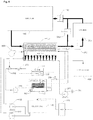
- the water is initially circulated out of the emitter 100 through a chiller 120 using a pump 260 that continually chills the water.
- the chilled water flows back into the emitter through a series of 'condenser' pipes 200 in the air space above the water in the emitter ( Fig. 7A ).
- the target humidity in the enclosed space to be fumigated is reached by passing the air from the building 140 using a fan 130 through emitter 100. Due to the cold water at dew point temperature circulating through the condenser pipes in the emitter, the humidity in the air passed through the emitter 100 will drop as water vapor is condensed out of the air.
- the de-humidified air will then go back into the building 140. This process is continued in a cycle until the target relative humidity in building 140 is achieved, and then fumigation can begin.
- valve configuration (210,220, 230) of the system allows all of the water in the emitter 100 to pass directly through the chiller 120, which brings the water in the emitter 100 down to the required dew point temperature.
- water is kept circulating through the condenser coils 200 in the top of the emitter 100, while air is pumped from the building using a fan 130 through the top space in the emitter, such that air passes over the cold condenser coils 200.
- fumigation can start.
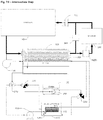
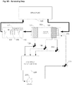
- the valve configuration (220, 230) in the system is then switched over so that the chiller 120 is controlling the temperature of water in a separate tank 110 containing a double wall counter flow heat exchanger 115 ( Fig. 7B ). This is done to avoid having to put the chlorine dioxide solution directly through the chiller 120.
- chlorine dioxide solution is injected into the emitter 100 where the bubbling air through the water in the emitter 100 strips the gas out and then carries it into the building 140.
- the water in the emitter is continuously passed through the heat exchanger 115, which is sitting in the middle tank 110 of cold water that is kept cold by the chiller 120. This maintains the dew point temperature of the water in the emitter.
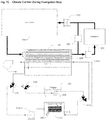
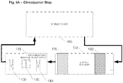
- the valves in the system are configured for the Climatization Step (7A).
- the water is going directly from the emitter to the chiller and air is passed from the building to the emitter to de-humidify it.
- the valves are configured so that the chiller cools the middle tank of water 110 that holds a heat exchanger 115 to about dew point temperature . To accomplish this, water moves from chiller 120 to middle tank 110 and then back to the chiller 120.
- the valves (210, 220, 230) are configured such that water from the emitter 100 is pumped through the heat exchanger 115 sitting in middle tank 110.
- the water circulating from emitter 100 passes through the heat exchanger in middle tank 110, while the water in middle tank 110 is kept at about dew point by chiller 120.
- the cold water in the middle tank 110 is continuously circulated in a counter flow through the heat exchanger by a small submersible pump 105 in the middle tank 110 for maximum cooling efficiency.
- the system's air loop is under balanced pressure. This is accomplished by the use of fan 130, which draws air (via suction) from building 140 through the emitter 100 and scrubber 280, then back in again.
- fan 130 operates at about 141.6 cubic meters per minute (5000 cubic feet per minute (CFM)).
- blower 150 takes a small amount of air from the building 140 and passes it through the water in emitter 100 in order strip the chlorine dioxide gas. In a preferred embodiment, blower 150 operates at about 2.8 cubic meters per minute (100 CFM).
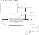
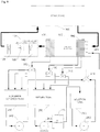
- Fig. 8 water is pumped from the emitter 100 by a pump 250 through a chlorine dioxide generator 170 and into a solution holding tank 180 ( Fig. 8A ). The solution is then pumped from the solution holding tank 180 into the emitter 100 using pump 190 ( Fig. 8B ). Pump 200 is used as a backup pump to increase the flow of solution to the emitter if required. Chlorine dioxide is stripped from the solution in the emitter 100 by means of the blower 150 blowing air through the water in the emitter.
- waste storage tank 160 into which excess fluid can be pumped from the system by pump 250 through valve 240 in order to remove volume from the system.
- the entire system in Figs. 6-8 is designed to both pump gas into the building and to maintain the target relative humidity within the building. In one embodiment, this is accomplished by keeping the air in the emitter at the dew point temperature. According to this embodiment, when the air enters the building, it will be warmed because of the higher temperature in the building (e.g., about 23.9° C (75° F)). As the temperature of the air from the emitter rises, the relative humidity will drop. In other words, the air in the emitter is at dew point so that any gas that is bubbled through and pumped into the building is essentially at saturation (100% RH). When this enters the building and warms up, the humidity will drop to the target RH
- the gas is removed from the air in the building. This is achieved by closing damper 300 and opening damper 290 and passing the air through a scrubber 280.
- the scrubber can be a container of activated carbon, or a liquid scrubber using an alkalizing and dechlorinating agent or other functional chemistry (e.g., ascorbic acid).
- the air is continuously circulated through the scrubber until the measured concentration of chlorine dioxide gas in the air in the structure has been reduced to below the target concentration.
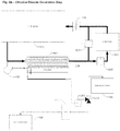
- Fig. 9 schematically illustrates a further embodiment of the invention.
- lowering the relative humidity in an enclosed space or structure such as a building or home, and introducing chlorine dioxide gas to the structure can be accomplished by the use of an emitter/scrubber, which functions as both an emitter and a scrubber, and an air handling unit which functions both as a dehumidifier and air reheat unit.
- an emitter/scrubber which functions as both an emitter and a scrubber
- an air handling unit which functions both as a dehumidifier and air reheat unit.
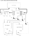
- air is pulled under suction from the structure 100, through the emitter/scrubber 150, through the air handling unit 110 and recirculated back into the structure by means of a fan 120.
- the fan 120 which may be part of or separate from the air handling unit, may be placed at any point in the air re-circulation loop.
- a refrigeration coil 140 is set at a temperature sufficient to remove moisture from the air and thereby achieve the target relative humidity.
- the air passing over the coil 140 is effectively chilled to a temperature near to that of the coil.
- the relative humidity of the air leaving the coil is approaching 100% at this point.
- the air is reheated to the temperature of the air in the building with a heating coil 130.
- the reheat coil may be electrical, or may use waste heat from the refrigeration process, or a combination of both.
- the refrigeration and reheat capacity of the air handling unit may be sized to achieve the desired target relative humidity with one pass of the air through the air handling unit, or to achieve the desired target relative humidity after two or more passes of the air through the air handling unit.
- fan 120 which draws air (via suction) from the structure 100, through the emitter/scrubber 150, through the air handling unit 110, and then back into the structure.
- fan 120 operates at a preferred flow rate of about 85 cubic meters per minute (3000 cubic feet per minute (CFM)). Fan 120 may operate at any flow rate provided that it does not exceed the air flow rate design parameters of the refrigeration coil 140 or the reheat coil 130.
- first water is added to the return tank 250 in a sufficient volume to meet the needs of the chlorine dioxide generation process.
- the preferred volume is about 946.4 liters (250 US gallons).
- Pump 260 is switched on to pump the water from return tank 250, through the chlorine dioxide generator 270, and into the solution tank 290. This continues until all the water in return tank 250 has been transferred through the generator 270 into the solution tank 290.
- the air flow through the emitter/scrubber 150 and air handling unit 110 is maintained by fan 120 with both the refrigeration coil 140 and the reheat coil 130 functioning, so that any humidity introduced in the air stream by the emitter/scrubber is removed before the air is returned to the structure.
- the emitter/scrubber first has to be configured to function as an emitter.
- the valves 180, 190 and 200 on the emitter/scrubber drains are configured so that any liquid draining from the emitter/scrubber drains back into the return tank 250.
- Valve 210 is then configured so that fluid from pump 280 is directed through the spray header bar 220 in the emitter/scrubber 150.
- pump 280 With air flowing through the emitter/scrubber, pump 280 is turned on to send chlorine dioxide solution to the emitter/scrubber through the spray head 220.
- An impingement bank 160 in the emitter/scrubber ensures intimate contact between the chlorine dioxide solution and the air. This contact enables chlorine dioxide gas to be released from the solution and enter the air stream.
- Depleted chlorine dioxide solution drains from the emitter/scrubber 150 back into the return tank 250 via valves 190 and 200.
- a mist eliminator 170 is utilized to remove water droplets from the air leaving the emitter scrubber. Liquid taken from the air by mist eliminator 170 drains back into the return tank 250 via valve 180.
- the depleted chlorine dioxide solution is then pumped from the return tank 250 through the chlorine dioxide generator 270 by pump 260 into the solution tank 290. This recharges the spent solution with chlorine dioxide ready for return to the emitter/scrubber by pump 280. This process continues until the required concentration of chlorine dioxide has been reached in the structure and held for the required time at that concentration to achieve the target CT.
- pump 280 When the required concentration of chlorine dioxide has been maintained in the structure for the required time period to achieve the target CT, pump 280 is turned off and the scrubbing process to remove the chlorine dioxide gas from the structure can commence.
- the air flow through the emitter/scrubber 150 and air handling unit 110 is maintained by fan 120 with both the refrigeration coil 140 and the reheat coil 130 functioning, so that any humidity introduced in the air stream by the emitter/scrubber is removed before the air is returned to the structure.
- the emitter/scrubber 150 has to be configured for use as a scrubber.
- Valves 180, 190 and 200 on the emitter/scrubber drains are configured so that any fluid from the emitter/scrubber drains into the scrubber solution tank 220.
- Valve 210 is configured so that the flow from pump 230 is delivered to the spray head 220 in the emitter/scrubber.
- the scrubber tank 220 is filled with sufficient scrubber solution and at a concentration required to remove the quantity of chlorine dioxide gas that remains in the structure.
- the scrubber solution may be an alkalizing and dechlorinating agent or other chemical agent suitable for scrubbing chlorine dioxide gas from an air stream.
- Pump 230 is switched on to pump scrubber fluid via valve 210 to the spray header 220 in the emitter/scrubber 150.
- An impingement bank 160 in the emitter/scrubber ensures intimate contact between the air stream containing chlorine dioxide gas and the scrubber solution. This contact enables chlorine dioxide gas to react with the scrubber solution and be removed from the air stream.
- Scrubber solution drains from the emitter/scrubber impingement bank 160 to the scrubber solution tank 220 via valves 190 and 200.
- a mist eliminator 170 is utilized to remove water droplets from the air leaving the emitter/scrubber. Liquid taken from the air by mist eliminator 170 drains back into the scrubber solution tank 220 via valve 180.
- the scrubber solution is pumped through the emitter/scrubber, and the air from the structure is recirculated through the emitter/scrubber until the measured concentration of chlorine dioxide gas in the air in the structure has been reduced to below the target concentration.
- the return tank 250, solution tank 290 and scrubber solution tank 230 are sized for sufficient volume to contain all the introduced liquids.
- the system may need to be configured to increase the relative humidity to a target value in the enclosed space to be fumigated.
- chlorine dioxide is not stable at partial pressures over 83 millimeters of mercury, it is not available for purchase in high-pressure gas cylinders. Therefore chlorine dioxide gas must be generated at the decontamination site for subsequent introduction into an enclosed space to be fumigated.
- chlorine dioxide solutions can be produced by treatment of chlorite salt solutions (e.g. NaClO 2 ) with an acid solution to produce acidic solutions that contain ClO 2 , which can be then be flushed as a gas into water to produce aqueous ClO 2 .
- chlorite salt solutions e.g. NaClO 2
- Other precursors such as sodium chlorate can also be used.
- the present invention provides a process that comprises producing chlorine dioxide by using an apparatus such as a chlorine dioxide generator, e.g. as disclosed and claimed in U.S. Pat. No. 6,468,479 .
- the chlorine dioxide is generated either directly as a gas, or preferably as an aqueous (or other suitable liquid carrier) chlorine dioxide mixture.
- the generator is preferably run using an excess of sodium chlorite to reduce the possibility of generating chlorine gas as an impurity.
- Other generally accepted methods for generating chlorine dioxide can be found in, for example, U.S. Patent Pub. No. 2006/0068029 ( U.S. Pat. App. No. 11/131021 ).
- the same equipment described in the above climatization step and shown in Figs. 6-8 is used to a) introduce the chlorine dioxide gas into the volume requiring remediation, b) distribute the introduced chlorine dioxide gas within the volume, and c) maintain the chlorine dioxide gas within the volume at a concentration and for a sufficient duration to permit the gas to penetrate included contents as required for fumigation.
- the generated chlorine dioxide is transferred directly or alternatively, indirectly via a storage tank, to the emitter.
- the emitter is an apparatus such as the stripper discussed above and shown in Figs 6-8 .
- the emitter is operated to maintain the gaseous chlorine dioxide concentration substantially below the explosion limit of chlorine dioxide in the air.
- the emitter is a combined emitter/scrubber as described above and shown in Fig. 9
- the relative humidity must be maintained at the target percentage for the particular application. Therefore, the climatization to achieve the target relative humidity (i.e. via de-humidification or humidification) and the remediation are performed simultaneously using the same apparatus by the appropriate adjustment in the temperature of chlorine dioxide solution, or by using an air handling unit that combines dehumidification and air reheating.
- illumination levels may also be reduced within the enclosed space, preferably to substantial darkness, to minimize the decomposition of chlorine dioxide to chlorine.
- the process is monitored with the use of an infrared camera or similar device. Temperature, relative humidity, concentration of decontamination agent, and contact time typically will be measured and recorded throughout the decontamination process.
- variable generation rate of chlorine dioxide gas is initiated.
- the initial rate is high to provide sufficient chlorine dioxide to penetrate the various materials within the volume requiring remediation.
- This rate is predetermined to accommodate the material demand as well as to provide the initial charge of the volume requiring remediation to a predetermined chlorine dioxide residual level.
- the chlorine dioxide generation rate is then reduced appropriately to maintain the predetermined chlorine dioxide concentration in the air of the volume requiring remediation for a predetermined time. This can be achieved by various means, for example, lowering the concentration of chlorine dioxide in the solution that is fed to the emitter, or lowering the flow rate of the chlorine dioxide solution to the emitter.
- the chlorine dioxide gas concentration is determined to compensate for the decay or loss rate from the volume requiring remediation.
- the volume requiring remediation is preferably to be at slightly negative pressure to areas outside of it, and the volume may be sealed off through the use of a strippable sealant, for example, a hardenable foam.
- the volume to be remediated can be enclosed within a substantially light impervious tent while undergoing remediation so as to avoid light-induced degradation of the introduced chlorine dioxide gas.
- the tent is substantially impervious to gas.
- the generator, storage and emitter are purged with fresh water. Subsequently the water may be injected with an alkalizing and dechlorinating agent or other agent that will scrub the chlorine dioxide. This scrubbing solution is then fed to the emitter and with the blowers still in operation, and the emitter begins to scrub chlorine dioxide out of the environmental air composition within the volume that has been remediated.
- the chlorine dioxide can be scrubbed from the environmental air by passing the air through a separate scrubber system containing water injected with an alkalizing and dechlorinating agent or other agent that will scrub the chlorine dioxide. This process is continued until the environmental air composition within the volume that has been remediated is returned to acceptable limits for reopening the exterior environment to re-habitation.
- the emitters can be located inside or outside of the volume requiring remediation. However, it is highly preferred to locate the emitter inside the volume requiring remediation, since then no contaminated air is allowed to leave the volume requiring remediation.
- a 232.2-square meters (2500-square foot) building structure was encapsulated and prepared for treatment with chlorine dioxide gas.
- the structure was maintained under a negative pressure by withdrawing from 50 to 100 CFM of air from the structure though out the treatment process.
- the withdrawn air was scrubbed though carbon filters to prevent the discharge of chlorine dioxide.
- Temperature and relative humidity were monitored at six locations throughout the structure.
- An external six ton HVAC system was connected to the home to provide temperature and humidity control.
- a six thousand 1b per day (2721.5 kg/day) chlorine dioxide system with the appropriately sized gas strippper was used to apply chlorine dioxide to the building structure.
- Chlorine dioxide gas was added to the structure to achieve a concentration ranging from 2800 to 3800 ppmv throughout the structure.
- chlorine dioxide was added to the structure to maintain these concentrations.
- the relative humidity was maintained within the structure between 32 and 45%.
- the concentration-time (CT) of chlorine dioxide in the structure was 37,000 ppmv/hours.
- a structure was prepared for fumigation with chlorine dioxide gas by enclosing the structure within an envelope, installing a scrubbing system upon the structure to maintain a negative pressure within the envelope, and installing temperature and humidity control equipment to maintain environmental levels.
- the structure had a footprint of approximately 297.3 square meters (3200 square feet) and a volume of 1500.8 cubic meters (53000 cubic feet).
- Chlorine dioxide was added continuously for about 14 hours to maintain an average concentration of about 3800 ppmv.
- the total treatment of the structure was an average of 52,000 ppmv hours of chlorine dioxide.
- the drywall Prior to the treatment of 10 locations, the drywall was sampled to determine the presence of bacterial growth by culture for anaerobic, aerobic, and sulfate reducing bacteria. All locations exhibited growth on the wallboard surface, within the front and back wallboard paper, and within the core of the gypsum. All locations exhibited bacterial growth. Six log spore strips were inserted deep into the wall cavities prior to the fumigation. All wall penetrations made during sampling were sealed with "plumber's plugs" prior to fumigation.
- Post fumigation no bacterial growth was observed at any of the sample locations. All spore strips were completely inactivated. Post fumigation numerous types of insects and arachnids, including ants, flies, larvae, bees, termites, and spiders were observed dead throughout the structure. Numerous geckos on the walls and floors within the fumigated volume were also found dead post fumigation.
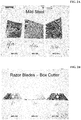
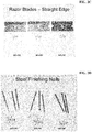
- Metals such as exposed, scuffed mild steel and high carbon steel known to be sensitive to chlorine dioxide fumigation at high humidities were examined at six hours, thirty days, and sixty days following fumigation. No evidence of corrosion due to the fumigation was observed.
- Each of the structures was fumigated with chlorine dioxide gas at concentrations from 1500 ppmv to 4500 ppmv chlorine dioxide.
- the chlorine dioxide concentration -time (CT) ranged from 9000 ppm v hours to 54,000 ppm v hours. All of the structures were inspected immediately post fumigation and 30 days after fumigation. No corrosion or rusting was observed in any of the structures. All of the highly sensitive materials were corrosion-free post fumigation on the immediate and 30 day evaluations.
- Humidity measured in the structures prior to fumigation ranged from 65% to 80%. Immediately prior to fumigation, the relative humidity levels were adjusted to 48% or less using a humidity control system. The process used a cooling coil to remove moisture from the air and a reheating coil to maintain temperature within the structure.
- the structures were purged with outside air for a period of 72 hours.
- the purge air temperature ranged from 18.3 °C (35°F) to 23.9 °C (75°F) and from 40% to 85% relative humidity.
- Penetration of chlorine dioxide throughout the structure was verified by culture tests of the drywall core and by the insertion of "spore strips" within the structure walls. Chlorine dioxide kill, and thus penetration, was demonstrated on all of the core samples and all of the inserted spore strips on all of the tests and all of the structures.
- ClO 2 fumigation process One technology that shows great promise for solving the Chinese wallboard problem is a gaseous chlorine dioxide (ClO 2 ) fumigation process originally developed by Sabre Technical Services, LLC (Sabre) while assisting USEPA and the US Postal Service (USPS) in devising a technical solution to widespread Bacillus anthracis (i.e. anthrax) contamination present in buildings following the anthrax attacks of 2001.
- Sabre's ClO 2 fumigation technology was used to eliminate anthrax contamination from the Hart Senate Office Building and USPS Curseen-Morris Processing and Distribution Center (P&DC) in Washington, DC, the USPS Trenton P&DC in Hamilton Township, New Jersey and the former American Media, Inc. Building in Boca Raton, Florida.
- the size of these ClO 2 fumigation applications ranged from a low of 2831.7 cubic meters (100,000 cubic feet (ft 3 )) to a high of over 396436 cubic meters (14 million ft 3 ).
- a major complication in determining success of ClO 2 in eliminating reduced-sulfur compounds from an affected structure is the difficulty of measuring and analyzing these gases at the low concentrations they are present at within the structure.
- Sabre used various surrogate measures to document the efficacy of ClO 2 gas in ridding the test structure of reduced-sulfur compounds.
- atrophaeus species is widely recognized as being the most difficult to inactivate with ClO2 gas. Pervasive inactivation of BIs in "hard to reach" areas of the structure (i.e. inside wall cavities) thus indicates that pervasive oxidation of reduced- sulfur compounds also occurred throughout the structure.
- Reduced- sulfur compounds odors are extremely noxious and can be detected by the human olfactory (i.e. odor) sense at levels which are at or below the detection limits of sophisticated analytical instruments.
- the olfactory senses of both Sabre personnel and independent observers were employed both pre- and post-treatment to gauge the effectiveness of ClO2 in ridding the test structure of reduced- sulfur compound odors.
- This 225.6 square meters (2,429 square foot) two-story home consists of 3 bedrooms, 3.5 baths, a kitchen, grand room, dining room, laundry room and an attached 2-car garage.
- This home also has an adjacent 26.6 square meters (286 square foot) guest cabana consisting of 1 bedroom, 1 bathroom and a small kitchen.
- the main home and guest cabana are connected by a private courtyard with a screen ceiling enclosure, brick foundation and small spa.
- the entire structure, including main home, guest cabana and private courtyard was enclosed with impermeable polyethylene sheeting material during the fumigation to prevent release of ClO 2 gas to the surrounding environment.
- Pre- and post-treatment SRB samples were collected from wallboard material throughout the structure to assess efficacy of the ClO2 gas in inactivating bacteria present within them, and thus oxidizing any reduced-sulfur compounds.
- BI spore strips were also placed in representative locations throughout building wall cavities to document that pervasive gas penetration occurred throughout the structure.
- Temperature and RH -- Temperature and RH conditions within the structure were monitored throughout the fumigation at four representative locations. Each monitored location was deemed to be a potential problem area for controlling temperature and RH conditions based on the home's heating, ventilation and air conditioning (HVAC) system and airflow movement characteristics. Selected monitoring locations were in the 1st floor master suite closet; inside the attic access point in the garage; in the guest cabana kitchen; and inside the attic access point in the 2nd floor suite #2 closet.
- HVAC heating, ventilation and air conditioning
- the target temperature and RH conditions chosen for the fumigation were a temperature of 26. 6°C ⁇ 2.8°C (80oF ⁇ 5° F) and an RH level of 45% ⁇ 5% at all monitoring locations.
- Temperature and RH levels were monitored through use of HOBO® Model U 12-011 TEMP/RH Data Loggers manufactured by Onset Computer Corporation.
- the instrument temperature measuring range is -20 to 70°C (-4 to 158°F) with an accuracy of ⁇ 0.35°C ( ⁇ 0.63 °F).
- the RH measuring range is 5% to 95% with an accuracy of ⁇ 2.5 %. Temperature and RH measurements were monitored on a real-time basis and logged at 5-minute intervals throughout the fumigation process.
- ClO2 Concentrations and CT Values -- ClO2 concentration levels were monitored throughout the fumigation process at the same four representative locations selected for temperature and RH monitoring. These locations were, again, selected based on knowledge of the home's HVAC systems and airflow movement characteristics.
- the target ClO 2 parameters selected for this project were an average concentration of 500 ppm v or more and a CT value not less than 2,000 ppmv-hours nor more than 9,000 ppmv-hours at all monitoring locations. Monitoring of ClO 2 concentrations began shortly after the gas was first introduced into the structure and continued at periodic intervals throughout the fumigation process.
- HDPE tubing 0.63cm (one-quarter inch) inside diameter high-density polyethylene (HDPE) tubing.
- the HDPE tubing was run from the four designated monitoring locations to a central sampling manifold located outside the building in a mobile laboratory facility. Samples were collected and analyzed by trained technicians. Air flowed continuously to the sampling manifold so that samples represented existing conditions within the building at the time they were taken. A vacuum pump was placed on the downstream side of the sampling manifold to move air through the system and return it to the structure on a continuous basis throughout the fumigation process.
- Samples were collected from the sampling manifold via impingement of two liters of air at a flow rate of 1.0 liter per minute through 15 milliliters of a strongly buffered pH 7 potassium iodide solution (modified US Occupational Safety and Health Administration Method ID126SGX). Once collected, samples were analyzed by colorimetric titration, using a 0.1 normal sodium thiosulfate solution as the titrant (modified American Water Works Association Method 4500-ClO 2 -E and modified 2-step version of same).
- a fumigation ClO 2 CT dose "clock” was started for each of the four co-located monitoring points when temperature and RH conditions had equilibrated in their desired ranges and gas introduction into the structure had begun. Once started, each CT clock accumulated ClO 2 exposure "credit" until the target dose level had been achieved at each monitoring location, at which time the fumigation was deemed complete.
- SRBs The efficacy of ClO 2 gas in eliminating SRBs from Chinese wallboard material was evaluated by collecting samples of unpainted wallboard paper located inside wall cavities of the home prior to, and immediately after, ClO 2 exposure. Unpainted wallboard paper from wall cavities was chosen for SRB testing because preliminary laboratory work done at Sabre's Slingerlands, NY laboratory facility had shown SRBs to be concentrated in this media.
- Pre-treatment wallboard paper samples were collected by drilling a 5.08cm (two- inch) circular core at selected wall and ceiling locations. To avoid damaging vapor barriers present within the home, samples were not collected from any bathroom or laundry room locations. Sample locations were selected to be representative wall cavities within the structure most likely to contain conditions conducive to SRB growth. In total, 20 sample locations were selected. Nine were wall cores and eleven were ceiling cores.
- the wallboard holes created through SRB sampling were each sealed using a 5.08cm (two-inch) rubber expansion plug in order to ensure that ClO 2 gas would not penetrate into wall cavities as a consequence of sampling activities.
- Post-treatment wallboard paper samples were collected by drilling an identical 5.08cm (two-inch) circular core approximately one inch away from each of the 20 pre- treatment sample locations.
- BI Spore Strips - BI spore strips, each containing an approximate 2.5 x 10 3 titer of B. atrophaeus spores, were placed within wall cavities of the structure at the same 20 locations where wallboard samples had been collected, prior to insertion of the 5.08cm (2-inch) expansion plugs.
- the B. atrophaeus species was selected due to its historical use as a biological indicator for ClO 2 fumigations
- Spore strips are thin cellulose pads that have been impregnated with a defined titer of bacterial spores. Each spore strip is encased in a Tyvek® pouch to allow for effective penetration of fumigant gas yet protect the strip from contamination by external sources.
- the BIs were obtained from SGM Biotech Inc., 10 Evergreen Drive, Suite E, Bozeman, MT (Lot # ACD-113e). All BIs were supplied from the same product batch in order to ensure uniformity in spore titer. Relevant production QA/QC data for the specific lot number have been kept on file for future reference.
- BIs were retrieved promptly following fumigation and sent to Sabre's Slingerlands, NY laboratory facility for analysis.
- Each spore strip was aseptically placed in a growth media tube containing 15 milliliters of trypticase soy broth (BD Diagnostics product #221823, Lot # 7337460) and incubated at 37°C. Spore strips were evaluated daily for the presence or absence of indicator organism growth for a total of seven days.
- Corrosivity potential was assessed by observation of typical metal items present within the structure (e.g. screws, door hinges, HVAC system components, etc.).
- Several pieces of copper pipe were also placed on the cafe countertop for the duration of fumigation to verify that ClO 2 would not cause any adverse effects such as corrosion or discoloration.
- Each piece of copper was "scuffed” clean prior to fumigation to ensure that any changes in the metal due to ClO 2 exposure would be readily recognizable. Photographs were taken of the copper pipe pieces before and after treatment to document visual observations made.
- Bleaching potential of ClO 2 was assessed by observation of carpet color and brightness throughout the structure both pre- and post-treatment. A piece of carpeting was also removed from a closet within the structure prior to fumigation and used for direct visual comparison with treated carpet following completion of the process.
- Odor levels emanating from within the structure were observed both pre- and post-treatment for the "putrid" characteristic commonly associated with reduced- sulfur gases such as hydrogen sulfide, carbonyl sulfide and carbon disulfide that have been definitively shown by an FDOH study as being released from Chinese wallboard.
- Positive control BIs were submitted to the Sabre laboratory for viability testing along with the fumigated BIs in a ratio of approximately one positive control sample for every 10 treated samples, for a total of two positive controls. Positive controls are untreated (i.e., not fumigated) BIs of identical composition that are submitted to the laboratory along with the exposed BIs. Positive controls provide evidence of BI product quality as well as evidence that appropriate conditions for growth of the surrogate test organism were achieved. The positive control samples were handled, packaged and shipped in the same manner as the actual samples from the building, except that the positive controls were not subjected to the fumigant gas.
- Temperature & RH -- Raw temperature and RH data were exported from the HOBO® data loggers into a Microsoft Corporation Excel® spreadsheet for purposes of calculating mean temperature and RH levels for each monitoring location. These mean temperature and RH values ( ⁇ one standard deviation) are shown in Table 1.
- the SRB growth data indicated a widespread presence of SRBs within the unpainted wallboard paper prior to fumigation. Twelve of 20 sample locations were found to be positive for SRBs prior to ClO 2 treatment. Following treatment, all 20 locations were determined to be negative for SRB growth.
- the ClO 2 fumigation process was shown capable of inactivating SRBs present within wallboard material, as well as BI spore strips embedded within wall cavities, thereby demonstrating the ability of ClO 2 gas to completely permeate an affected structure and oxidize reduced sulfur compounds at the CT values employed. In addition, it was demonstrated that ClO 2 would not cause unacceptable changes within a treated structure in terms of metal corrosion or material bleaching.
Landscapes
- Health & Medical Sciences (AREA)
- Animal Behavior & Ethology (AREA)
- Public Health (AREA)
- Veterinary Medicine (AREA)
- Epidemiology (AREA)
- Life Sciences & Earth Sciences (AREA)
- General Health & Medical Sciences (AREA)
- Chemical & Material Sciences (AREA)
- Organic Chemistry (AREA)
- General Chemical & Material Sciences (AREA)
- Chemical Kinetics & Catalysis (AREA)
- Inorganic Chemistry (AREA)
- Apparatus For Disinfection Or Sterilisation (AREA)
- Agricultural Chemicals And Associated Chemicals (AREA)
- Catching Or Destruction (AREA)
Description
- This application claims the priority from
U.S. Provisional Application No. 61/184,298, filed June 4, 2009 - The disclosure of the application entitled REMEDIATION OF GYPSUM BOARD USING GASEOUS CHLORINE DIOXIDE, has been contemporaneously filed on April 28, 2010.
- The invention relates to a method of remediation or decontamination of an enclosed space using gaseous chlorine dioxide under conditions that mitigate or eliminate corrosion. A prior art method is known, e.g., from
WO 2007/118159 A2 . - The use of chlorine dioxide (ClO2) as a sterilizing agent is known. Chlorine dioxide, a powerful oxidant and disinfectant, has been employed in a wide spectrum of gas phase applications, including the disinfection of food, odor control, Anthrax and other microbial decontamination, mold remediation, Chinese wallboard remediation, disinfection of medical waste, and oil and gas injection well stimulation.
- For example, chlorine dioxide gas was used in 2001 to decontaminate the Hart Senate Office Building in Washington, D.C., after the discovery of a letter containing Bacillus anthracis spores (Anthrax).
U.S. Patent Appl. No. 11/270,973 (US Patent Pub. No. 2006/0228253 ) discloses a method for the large-scale use of chlorine dioxide gas for fumigation and sterilization. Similarly, chlorine dioxide gas has been used to decontaminate mail processing and other commercial buildings in D.C., New Jersey and Florida after the discoveries of anthrax there. -
US Appl. No. 11/576,498 US Patent Pub. No. 2009/0081310 ) discloses a method for the effective large-scale use of chlorine dioxide for mold remediation. -
U.S. Prov. Appln. Nos. 61/173,844 61/252,422 -
WO 2007118159 discloses a method for applying gaseous chlorine dioxide within an enclosed volume, where the relative humidity is kept within a range between 65 and 80%.US 2004/0259188 discloses a method of decontamination using chlorine dioxide and teaches that the efficacy of the decontamination depends on the relative humidity and the concentration of the gas. - Despite the numerous successes and general acceptance of chlorine dioxide as a viable fumigant, there is a serious drawback to its widespread use as a gas phase sterilant. Because ClO2 is highly oxidizing, it is prone to exhibit corrosion on certain items located within an enclosed structure upon completion of the fumigation treatment. Although it is well known in the art that the chlorine dioxide is less corrosive than chlorine to metals, it has been shown that gas phase application of chlorine dioxide can result in the corrosion of certain metals that are found within a building, either in the structure itself or in the contents located within.
- It is an aspect of this invention to mitigate corrosion of the contents within a building, such as electronic equipment (e.g., telephone equipment, computers, copiers, and other electronic office equipment), furnishings, and the like, while still accomplishing successful decontamination using gaseous chloride dioxide.
- The present invention relates to a method for mitigating corrosion during the gas phase application of chlorine dioxide within an enclosed volume that comprises the steps of: climatizing the enclosed volume to a relative humidity not exceeding about 56%, generating chlorine dioxide gas: and introducing the chlorine dioxide gas into the enclosed volume at an effective concentration-time (CT) value to achieve the desired level of kill of targeted organisms or oxidation of contaminants.
- More specifically the
present invention relates to a method for gas phase application of chlorine dioxide within an enclosed volume that comprises the steps of: climatizing the enclosed volume to a relative humidity equal to x (%); generating chlorine dioxide gas; and introducing the chlorine dioxide gas into the enclosed volume at CT value of chlorine dioxide equal to y (ppmv-hrs), wherein y is equal to 6x 2. 870x + 32100 ± 1000, x being a number between 5 and 56 equal to the % RH. - The present invention further relates to a method for gas phase application of chlorine dioxide within an enclosed volume that comprises the steps of: climatizing the enclosed volume to achieve a relative humidity (RH) in the range of about 5% to about 56%, generating chlorine dioxide gas; and introducing the chlorine dioxide gas at a concentration ranging from 25 ppmv to 10,000 ppmv for the appropriate time into the enclosed volume to achieve a CT value of chlorine dioxide equal to y (ppmv-hrs); wherein y is equal to 6x 2. 870x + 32100 ± 1000, x being a number between 5 and 56 equal to the % RH.
- the present invention also relates to a method for gas phase application of chlorine dioxide within an enclosed volume
that comprises the steps of:
climatizing the enclosed volume to achieve a relative humidity (RH) in the range of about 5% to about 56%, generating chlorine dioxide gas; and introducing the chlorine dioxide gas under specified conditions of chlorine dioxide gas concentration and contact time, the specified conditions being effective to eliminate contaminants within the closed volume, and further to mitigate corrosion within the enclosed volume during the gas phase application. - In accordance with an aspect of the invention there is provided a method for gas phase application of chlorine dioxide within an enclosed volume, the method comprising the steps of: climatizing the enclosed volume at a temperature of 10 °C (50°F) to 32.2 °C (90°F) to achieve a relative humidity (RH) of 5% to 56%; generating chlorine dioxide gas and introducing chlorine dioxide gas into the enclosed volume at a concentration-time (CT) equal to y (ppmv-hrs), wherein y = 6x 2 - 870x + 32100 ± 1000, x being equal to the % RH, wherein the CT is the time-weighted average of chlorine dioxide concentration multiplied by the exposure time.
-
-
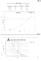
Fig. 1 is a graph summarizing treatment data for a corrosion study at 48% RH and 54% RH. -
Figs. 2A-2D are photographs of steel objects subjected to ClO2 at 48% RH and 54% RH. -
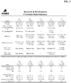
Fig. 3 is a table summarizing corrosion data for metal objects at various RH values. -
Fig. 4 is a plot of weight loss as a function of RH for mild steel. -
Fig. 5 is a plot of spore strip kill rate as a function of CT and RH. -
Fig. 6 is a schematic diagram of apparatus suitable for use in the method of the invention. -
Fig. 7 schematically depicts the use of the apparatus depicted inFig. 6 for control of humidity in the structure;Fig. 7A climatization,Fig. 7B intermediate, andFig 7C climate control during fumigation steps in the application of gaseous ClO2. -
Fig. 8A schematically depicts the use of the apparatus for the generation of ClO2. -
Fig. 8B schematically depicts the use of the apparatus for the introduction of gaseous ClO2 into the structure. -
Fig. 8C schematically depicts the use of the apparatus for pumping off excess fluid from the system. -
Fig. 9 is a schematic diagram of alternative apparatus suitable for use in the method of the invention. -
Fig. 9A schematically depicts the use of the apparatus for climatization. -
Fig. 9B schematically depicts the use of the apparatus for chlorine dioxide generation. -
Fig. 9C schematically depicts the use of the apparatus for the introduction of chlorine dioxide gas to the structure. -
Fig. 9D schematically depicts the use of the apparatus for the scrubbing of chlorine dioxide gas from the structure. - Based on past remediation efforts, it is generally accepted that in order to achieve adequate kill, chlorine dioxide fumigation of a building requires a minimum relative humidity (RH) of about 65%, with a target ClO2 concentration and exposure time of 750 ppmv for 12 hours, for a total concentration of 9000 ppmv-hrs (CT). Other researchers have recommended a RH of greater than 70% for ClO2 concentrations between 125 and 10550 ppmv. Under current EPA guidelines, applications of ClO2 for building remediation require 75% relative humidity and an exposure of 9000 ppmv-hrs.
- An EPA report issued September 2008, entitled Material Demand Studies: Interaction of Chlorine Dioxide Gas with Building Materials, described glove box tests carried out at RH above 75% and a temperature above 25°C on samples of carpet, painted steel, gypsum wallboard, ceiling tile, wood, and concrete. Concentrations of chlorine dioxide of 1000 ppmv and 2000 ppmv were employed, with a target CT of 12,000 ppmv-hrs. The chlorine dioxide demand varied with the type of building material, but significant operational problems were encountered during the tests, the result of corrosion of electronic components, flow meters, and pumps. Corrosion was also observed on the stainless steel parts within the test chamber.
- In the method of the present invention for gas phase application of chlorine dioxide within an enclosed volume to accomplish elimination of contaminants and mitigate corrosion therein, the enclosed volume is climatized to achieve a relative humidity (RH) in the range of about 5% to about 56%, preferably about 35% to about 53%, more preferably about 40% to about 52%, still more preferably about 45-50%, most preferably about 45% to about 48%. Climatizing the enclosed volume is carried out at a temperature of about 10°C (50°F) to about 32°C (90°F), preferably about 18°C (65°F) to about 29°C (85°F). "Elimination of contaminants" is defined as eliminating at least 95% of contaminants, or preferably eliminating at least 98% of contaminants, or more preferably eliminating at least 99% of contaminants.
- The contaminants within the enclosed volume may be selected from the group consisting of: bacteria, spores, molds, mycotoxins, allergens, insects, larvae, arachnids, lizards, and combinations thereof. The enclosed volume may include objects selected from the group consiating of metallic objects, non-metallic objects, and combinations thereof.
- Metallic objects within the enclosed volume may be formed from metals selected from the group consisting of steel, aluminum, iron, copper, chromium, lead, and combinations thereof. Non-metallic objects may be formed from materials selected from the group consisting of wood, brick, stone, cinder concrete, ceramic tile, ceiling tile, carpet, woven fabric, and combinations thereof.
- In one embodiment of the invention, the chlorine dioxide gas is introduced into the enclosed volume at a CT value of chlorine dioxide equal to y (ppmv/hrs), wherein y = 6x2 - 870x + 32100 ± 1000, x being equal to % RH In another embodiment, the chlorine dioxide gas is introduced into the enclosed volume at a concentration of about 25 ppmv to about 10,000 ppmv , preferably about 500 ppmv to about 30,000 ppmv.
- As used herein, "CT", or concentration-time, equals the time-weighted average of chlorine dioxide concentration multiplied by the exposure time in hours. In a plot of chlorine dioxide concentration versus exposure time in hours, the CT would equal the area under the curve. For example, if the time weighted average chlorine dioxide concentration over a 12-hour exposure period were 750 ppmv, the CT would be 9000 ppmv -hrs.
- In a gas or vapor phase application of chlorine dioxide, typical chlorine dioxide concentrations are in the range of 500 to 3000 ppmv, and exposure times are typically about 8 to 12 hours. For example, a time averaged chlorine dioxide gas concentration in the range of about 500 to 1500 ppmv over a 12 hour period has been found effective for killing mold spores and eliminating allergenic effects (CT = 6000 - 18000 ppmv-hrs). Similarly, a CT of 9000 ppmv-hrs has been found effective for sterilizing anthrax.
- Based on these ranges of chlorine dioxide concentrations, laboratory corrosion studies were conducted in a ClO2 exposure chamber in a laboratory. As seen in
Fig. 1 , the corrosive effect of chlorine dioxide on a select group of materials was determined at an average relative humidity of 48%, 53%, 54%, and 72%. At RH equal to 48%, 53%, and 54%, the studies were performed over a 6-hour time period using a concentration of chlorine dioxide sufficient to achieve a concentration-time of chlorine dioxide equal to approximately 9000 CT (ppmvhrs) for each sample. (SeeFigs. 1 and3 ). At RH equal to 72%, a concentration of chlorine dioxide was used sufficient to achieve a concentration-time of chlorine dioxide equal to approximately 6400 CT (ppmvhrs). (SeeFig. 3 ). The samples tested comprised aluminum; copper; galvanized steel; galvanized finishing nails; steel finishing nails; razor blades from a box cutter; razor blades from a straight edge razor; mild steel; and mild steel (scuffed). - In performing the corrosion tests, the target set points for each desired % RH level were as follows:
Target %RH Reheat Column/Chamber Temperature (°C) Chamber H2O Bath (°C) Stripper Column Temperature (°C) Stripper Column H2O Bath (°C) 45 21.1 (70 °F) 20 8.9 (48 °F) 0.5 55 21.1 (70 °F) 20 11.7 (53 °F) 7 65 21.1 (70 °F) 20 14.4 (58 °F) 11 - When the %RH needed to be lowered, the stripper column temperature was lowered. If the %RH needed to be raised, the stripper column temperature was raised. These temperature adjustments were done using the stripper column H2O bath. The opposite holds true for the reheat column/chamber. If the %RH needed to be lowered, the reheat column temperature was raised. If the %RH needed to be raised, the reheat column temperature was lowered. One must keep in mind that adjusting this set-point also affects the chamber temperature. All temperature adjustments were done using the reheat column/chamber H2O bath.
- First, both water baths were turned on and adjusted to desired set-points as set forth above. Then, the stripper column pump and chamber blowers were turned on. The stripper column was filled with cold tap water up to the drain line and the chamber hatch left open as the stripper column H2O bath chilled down to its set-point. Typically it took about 2 hours for the water bath to chill down. Once the set points were reached, the samples were placed in chamber and the hatch closed. To introduce ClO2, tap water was simultaneously emptied from the stripper column while charging it with ClO2 solution until it reached the drain line and fumigation would begin. While fumigating, the column was periodically charged with fresh ClO2 to reach desired concentrations and to maintain concentrations. The flow rate of chlorine dioxide solution was set at 800 mL/hour. When ready to end the fumigation, both of the evacuation ports were opened and a vacuum nozzle placed on the port farthest from the stripper column. While evacuating the chamber, the stripper column was flushed with fresh tap water until the water coming out of stripper column was clear. The samples were removed. Results from the corrosion test can be seen in
Figs. 2A-2D ,3 , and4 . - As shown in
Fig. 3 , regardless of RH or concentration of ClO2, little to no corrosion was seen in the aluminum, copper, galvanized steel, or galvanized finishing nails. In contrast, during gas phase application of chlorine dioxide, relative humidity is directly related to the amount of corrosion that occurs on steel finishing nails; razor blades from a box cutter; razor blades from a straight edge razor; and mild steel. (SeeFigs. 2A-2D and3 ). In other words, as the RH increases, the amount of corrosion increases. The corrosion weight loss exhibited in mild steel exposed to chlorine dioxide gas at increasing RH is shown inFig. 4 . - Laboratory studies were conducted to establish relative humidity and temperature test conditions. As seen in
FIG. 5 , the kill rates using chlorine dioxide were determined at an average relative humidity of 45%, 55%, 65% and 75%. Paper strips containing 106 Bacillus atrophaeus spores (spore strips) were placed in the fumigation chamber. The chamber and the test strips were allowed to stabilize for a minimum of one hour maintaining the target relative humidity and temperature conditions. Chlorine dioxide gas was then introduced to the chamber while maintaining these conditions for the specified concentration-time (CT) to meet the test conditions. The spore strips were then recovered and cultured to determine kill. - As can be seen in
Fig. 5 , a six log kill was achieved according to the following equation y = 6x 2 - 870x + 32100 ± 1000, wherein x is equal to relative humidity (%) and y is equal to CT, i.e. concentration-time of chlorine dioxide (ppmv - hrs). - As can also be seen in
Fig. 5 , at a RH of 45%, a six log kill can be achieved with a concentration-time of chlorine dioxide equivalent to 5100 CT (ppmvhrs). A CT of 5100 ppmvhrs is well within the range of acceptable chlorine dioxide levels as established by those of ordinary skill in the art and governmental agencies that set the standards for fumigation using chlorine dioxide. In fact, it is customary for the gas phase application of chlorine dioxide to use a CT of 9000 ppmv-hrs. A six log kill was achieved at a RH of approximately 35% using a CT of 9000 ppmv -hrs. - In contrast to prior gas phase applications of chlorine dioxide, which call for a high relative humidity (i.e. within the range of 65-70%) in the enclosed space to be fumigated, in this improved method it is necessary to achieve a target low humidity (approximately 45%). Prior to fumigation, an emitter may be used with water alone to lower (or raise, in some instances) the relative humidity in the volume requiring remediation. This is done by adjusting the temperature within the system and, in a preferred embodiment, is accomplished as follows.
- The present invention can be further understood by reference to
Figs. 6-8 , which schematically illustrates one embodiment of the invention. In a preferred embodiment, lowering the relative humidity in an enclosed space or structure such as a building or home can be accomplished by the use of an emitter and a chiller. First, referring toFIG. 6 , a volume of water is placed inemitter 100. In a preferred embodiment, approximately 0.61-0.91 m (2-3 feet) of water is placed in the bottom ofemitter 100. This water is then passed throughchiller 120 to take the temperature of the water down to the appropriate dew point temperature when compared to the temperature ofbuilding 140. For example, if the temperature in thebuilding 140 or other enclosed space to be fumigated is 23.9 °C (75°F), a dew point temperature of about 11.1 °C (52°F) is needed in the water. - To achieve this temperature, the water is initially circulated out of the
emitter 100 through achiller 120 using apump 260 that continually chills the water. The chilled water flows back into the emitter through a series of 'condenser'pipes 200 in the air space above the water in the emitter (Fig. 7A ). - Once the target dew point temperature in the
emitter 100 is reached, the target humidity in the enclosed space to be fumigated is reached by passing the air from thebuilding 140 using afan 130 throughemitter 100. Due to the cold water at dew point temperature circulating through the condenser pipes in the emitter, the humidity in the air passed through theemitter 100 will drop as water vapor is condensed out of the air. - The de-humidified air will then go back into the
building 140. This process is continued in a cycle until the target relative humidity in building 140 is achieved, and then fumigation can begin. - In other words, in the initial stage before fumigation begins, the valve configuration (210,220, 230) of the system allows all of the water in the
emitter 100 to pass directly through thechiller 120, which brings the water in theemitter 100 down to the required dew point temperature. Using this configuration, water is kept circulating through the condenser coils 200 in the top of theemitter 100, while air is pumped from the building using afan 130 through the top space in the emitter, such that air passes over the cold condenser coils 200. - Once the target relative humidity is reached in building 140, fumigation can start. The valve configuration (220, 230) in the system is then switched over so that the
chiller 120 is controlling the temperature of water in aseparate tank 110 containing a double wall counter flow heat exchanger 115 (Fig. 7B ). This is done to avoid having to put the chlorine dioxide solution directly through thechiller 120. During the fumigation process, as described in more detail below, chlorine dioxide solution is injected into theemitter 100 where the bubbling air through the water in theemitter 100 strips the gas out and then carries it into thebuilding 140. The water in the emitter is continuously passed through theheat exchanger 115, which is sitting in themiddle tank 110 of cold water that is kept cold by thechiller 120. This maintains the dew point temperature of the water in the emitter. - Referring to
Fig. 7 , first the valves in the system are configured for the Climatization Step (7A). In this initial start up step, the water is going directly from the emitter to the chiller and air is passed from the building to the emitter to de-humidify it. In Intermediate Step (7B), the valves are configured so that the chiller cools the middle tank ofwater 110 that holds aheat exchanger 115 to about dew point temperature . To accomplish this, water moves fromchiller 120 tomiddle tank 110 and then back to thechiller 120. Finally, in Climate Control During Fumigation Step (7C), the valves (210, 220, 230) are configured such that water from theemitter 100 is pumped through theheat exchanger 115 sitting inmiddle tank 110. The water circulating fromemitter 100 passes through the heat exchanger inmiddle tank 110, while the water inmiddle tank 110 is kept at about dew point bychiller 120. The cold water in themiddle tank 110 is continuously circulated in a counter flow through the heat exchanger by a smallsubmersible pump 105 in themiddle tank 110 for maximum cooling efficiency. - As also shown in
Fig. 6 , the system's air loop is under balanced pressure. This is accomplished by the use offan 130, which draws air (via suction) from building 140 through theemitter 100 andscrubber 280, then back in again. In a preferred embodiment,fan 130 operates at about 141.6 cubic meters per minute (5000 cubic feet per minute (CFM)). In addition,blower 150 takes a small amount of air from thebuilding 140 and passes it through the water inemitter 100 in order strip the chlorine dioxide gas. In a preferred embodiment,blower 150 operates at about 2.8 cubic meters per minute (100 CFM). - For the fumigation step, referring to
Fig. 8 , water is pumped from theemitter 100 by apump 250 through achlorine dioxide generator 170 and into a solution holding tank 180 (Fig. 8A ). The solution is then pumped from thesolution holding tank 180 into theemitter 100 using pump 190 (Fig. 8B ).Pump 200 is used as a backup pump to increase the flow of solution to the emitter if required. Chlorine dioxide is stripped from the solution in theemitter 100 by means of theblower 150 blowing air through the water in the emitter. - Finally, as chemicals are introduced into the system to generate chlorine dioxide, the volume of aqueous solution in the system increases. Therefore, in order to maintain a constant volume in the emitter, it is advantageous to provide for
waste storage tank 160 into which excess fluid can be pumped from the system bypump 250 throughvalve 240 in order to remove volume from the system. - The entire system in
Figs. 6-8 is designed to both pump gas into the building and to maintain the target relative humidity within the building. In one embodiment, this is accomplished by keeping the air in the emitter at the dew point temperature. According to this embodiment, when the air enters the building, it will be warmed because of the higher temperature in the building (e.g., about 23.9° C (75° F)). As the temperature of the air from the emitter rises, the relative humidity will drop. In other words, the air in the emitter is at dew point so that any gas that is bubbled through and pumped into the building is essentially at saturation (100% RH). When this enters the building and warms up, the humidity will drop to the target RH - When the required concentration of chlorine dioxide gas has been reached in the structure, and maintained for the required time to achieve the target CT, the gas is removed from the air in the building. This is achieved by closing
damper 300 andopening damper 290 and passing the air through ascrubber 280. The scrubber can be a container of activated carbon, or a liquid scrubber using an alkalizing and dechlorinating agent or other functional chemistry (e.g., ascorbic acid). The air is continuously circulated through the scrubber until the measured concentration of chlorine dioxide gas in the air in the structure has been reduced to below the target concentration. - The present invention can be further understood by reference to
Fig. 9 , which schematically illustrates a further embodiment of the invention. In this further embodiment, lowering the relative humidity in an enclosed space or structure such as a building or home, and introducing chlorine dioxide gas to the structure can be accomplished by the use of an emitter/scrubber, which functions as both an emitter and a scrubber, and an air handling unit which functions both as a dehumidifier and air reheat unit. - First, referring to
Fig. 9A , air is pulled under suction from thestructure 100, through the emitter/scrubber 150, through theair handling unit 110 and recirculated back into the structure by means of afan 120. Thefan 120, which may be part of or separate from the air handling unit, may be placed at any point in the air re-circulation loop. - During recirculation of the air through the
air handling unit 110, arefrigeration coil 140 is set at a temperature sufficient to remove moisture from the air and thereby achieve the target relative humidity. The air passing over thecoil 140 is effectively chilled to a temperature near to that of the coil. The relative humidity of the air leaving the coil is approaching 100% at this point. In order to achieve the desired relative humidity in the air leaving theair handling unit 110, the air is reheated to the temperature of the air in the building with aheating coil 130. The reheat coil may be electrical, or may use waste heat from the refrigeration process, or a combination of both. - The refrigeration and reheat capacity of the air handling unit may be sized to achieve the desired target relative humidity with one pass of the air through the air handling unit, or to achieve the desired target relative humidity after two or more passes of the air through the air handling unit.
- As also shown in
Fig. 9A , the system's air loop is under balanced pressure. This is accomplished by the use offan 120, which draws air (via suction) from thestructure 100, through the emitter/scrubber 150, through theair handling unit 110, and then back into the structure. In this embodiment,fan 120 operates at a preferred flow rate of about 85 cubic meters per minute (3000 cubic feet per minute (CFM)).Fan 120 may operate at any flow rate provided that it does not exceed the air flow rate design parameters of therefrigeration coil 140 or thereheat coil 130. - For the chlorine dioxide solution generation step, referring to
Fig. 9B , first water is added to thereturn tank 250 in a sufficient volume to meet the needs of the chlorine dioxide generation process. In this embodiment, the preferred volume is about 946.4 liters (250 US gallons).Pump 260 is switched on to pump the water fromreturn tank 250, through thechlorine dioxide generator 270, and into thesolution tank 290. This continues until all the water inreturn tank 250 has been transferred through thegenerator 270 into thesolution tank 290. - For the chlorine dioxide gas introduction step, referring to
Fig. 9C , the air flow through the emitter/scrubber 150 andair handling unit 110 is maintained byfan 120 with both therefrigeration coil 140 and thereheat coil 130 functioning, so that any humidity introduced in the air stream by the emitter/scrubber is removed before the air is returned to the structure. - To introduce chlorine dioxide gas to the air flow, the emitter/scrubber first has to be configured to function as an emitter. The
valves return tank 250.Valve 210 is then configured so that fluid frompump 280 is directed through thespray header bar 220 in the emitter/scrubber 150. - With air flowing through the emitter/scrubber, pump 280 is turned on to send chlorine dioxide solution to the emitter/scrubber through the
spray head 220. Animpingement bank 160 in the emitter/scrubber ensures intimate contact between the chlorine dioxide solution and the air. This contact enables chlorine dioxide gas to be released from the solution and enter the air stream. - Depleted chlorine dioxide solution drains from the emitter/
scrubber 150 back into thereturn tank 250 viavalves mist eliminator 170 is utilized to remove water droplets from the air leaving the emitter scrubber. Liquid taken from the air bymist eliminator 170 drains back into thereturn tank 250 viavalve 180. - The depleted chlorine dioxide solution is then pumped from the
return tank 250 through thechlorine dioxide generator 270 bypump 260 into thesolution tank 290. This recharges the spent solution with chlorine dioxide ready for return to the emitter/scrubber bypump 280. This process continues until the required concentration of chlorine dioxide has been reached in the structure and held for the required time at that concentration to achieve the target CT. - When the required concentration of chlorine dioxide has been maintained in the structure for the required time period to achieve the target CT, pump 280 is turned off and the scrubbing process to remove the chlorine dioxide gas from the structure can commence.
- For the scrubbing step, referring to
Fig. 9D , the air flow through the emitter/scrubber 150 andair handling unit 110 is maintained byfan 120 with both therefrigeration coil 140 and thereheat coil 130 functioning, so that any humidity introduced in the air stream by the emitter/scrubber is removed before the air is returned to the structure. - First, the emitter/
scrubber 150 has to be configured for use as a scrubber.Valves scrubber solution tank 220.Valve 210 is configured so that the flow frompump 230 is delivered to thespray head 220 in the emitter/scrubber. - The
scrubber tank 220 is filled with sufficient scrubber solution and at a concentration required to remove the quantity of chlorine dioxide gas that remains in the structure. The scrubber solution may be an alkalizing and dechlorinating agent or other chemical agent suitable for scrubbing chlorine dioxide gas from an air stream. -
Pump 230 is switched on to pump scrubber fluid viavalve 210 to thespray header 220 in the emitter/scrubber 150. Animpingement bank 160 in the emitter/scrubber ensures intimate contact between the air stream containing chlorine dioxide gas and the scrubber solution. This contact enables chlorine dioxide gas to react with the scrubber solution and be removed from the air stream. - Scrubber solution drains from the emitter/
scrubber impingement bank 160 to thescrubber solution tank 220 viavalves mist eliminator 170 is utilized to remove water droplets from the air leaving the emitter/scrubber. Liquid taken from the air bymist eliminator 170 drains back into thescrubber solution tank 220 viavalve 180. - The scrubber solution is pumped through the emitter/scrubber, and the air from the structure is recirculated through the emitter/scrubber until the measured concentration of chlorine dioxide gas in the air in the structure has been reduced to below the target concentration.
- To adequately contain all the volume of liquid introduced to the system by, for example, chemicals used for the generation of chlorine dioxide, or water used for flushing the systems, the
return tank 250,solution tank 290 andscrubber solution tank 230 are sized for sufficient volume to contain all the introduced liquids. - As described in
U.S. Application No. 11/576,498 and11/270,973 - Because chlorine dioxide is not stable at partial pressures over 83 millimeters of mercury, it is not available for purchase in high-pressure gas cylinders. Therefore chlorine dioxide gas must be generated at the decontamination site for subsequent introduction into an enclosed space to be fumigated. In general, chlorine dioxide solutions can be produced by treatment of chlorite salt solutions (e.g. NaClO2) with an acid solution to produce acidic solutions that contain ClO2, which can be then be flushed as a gas into water to produce aqueous ClO2. Other precursors such as sodium chlorate can also be used.
- Several chemical means of generating chlorine dioxide and their corresponding chlorine dioxide precursor chemicals are known in the art, and the choice of suitable means and chemicals is within the abilities of those skilled in the art. Exemplary chemical means of generating chlorine dioxide are disclosed in
U.S. Pat. Nos. 4,689,169 (Mason et al. ),5,204,081 (Mason et al. ),5,227,306 (Eltomi et al. ),5,258,171 (Eltomi et al. ),5,965,004 (Cowley et al. ), and6,645,457 (Mason et al. ). Because the goal is to eliminate corrosion, the chlorine dioxide should be of the highest possible purity. Specifically, chlorine gas should be present in the introduced chlorine dioxide gas at a level less than about 5%, preferably less than about 0.5%. - In one embodiment, the present invention provides a process that comprises producing chlorine dioxide by using an apparatus such as a chlorine dioxide generator, e.g. as disclosed and claimed in
U.S. Pat. No. 6,468,479 . The chlorine dioxide is generated either directly as a gas, or preferably as an aqueous (or other suitable liquid carrier) chlorine dioxide mixture. The generator is preferably run using an excess of sodium chlorite to reduce the possibility of generating chlorine gas as an impurity. Other generally accepted methods for generating chlorine dioxide can be found in, for example,U.S. Patent Pub. No. 2006/0068029 (U.S. Pat. App. No. 11/131021 ). - In another embodiment, the same equipment described in the above climatization step and shown in
Figs. 6-8 is used to a) introduce the chlorine dioxide gas into the volume requiring remediation, b) distribute the introduced chlorine dioxide gas within the volume, and c) maintain the chlorine dioxide gas within the volume at a concentration and for a sufficient duration to permit the gas to penetrate included contents as required for fumigation. - Aspects of this method are described in
U.S. Pat. Appl. No. 1 1/576,498 - In particular, the generated chlorine dioxide is transferred directly or alternatively, indirectly via a storage tank, to the emitter. In one preferred embodiment, the emitter is an apparatus such as the stripper discussed above and shown in
Figs 6-8 . The emitter is operated to maintain the gaseous chlorine dioxide concentration substantially below the explosion limit of chlorine dioxide in the air. In a further embodiment, the emitter is a combined emitter/scrubber as described above and shown inFig. 9 - As discussed above, throughout this step the relative humidity must be maintained at the target percentage for the particular application. Therefore, the climatization to achieve the target relative humidity (i.e. via de-humidification or humidification) and the remediation are performed simultaneously using the same apparatus by the appropriate adjustment in the temperature of chlorine dioxide solution, or by using an air handling unit that combines dehumidification and air reheating.
- In addition to controlling the relative humidity in the enclosed space by controlling the humidity and temperature, one of ordinary skill in the art will recognize that illumination levels may also be reduced within the enclosed space, preferably to substantial darkness, to minimize the decomposition of chlorine dioxide to chlorine. The process is monitored with the use of an infrared camera or similar device. Temperature, relative humidity, concentration of decontamination agent, and contact time typically will be measured and recorded throughout the decontamination process.
- Next, the variable generation rate of chlorine dioxide gas is initiated. The initial rate is high to provide sufficient chlorine dioxide to penetrate the various materials within the volume requiring remediation. This rate is predetermined to accommodate the material demand as well as to provide the initial charge of the volume requiring remediation to a predetermined chlorine dioxide residual level. The chlorine dioxide generation rate is then reduced appropriately to maintain the predetermined chlorine dioxide concentration in the air of the volume requiring remediation for a predetermined time. This can be achieved by various means, for example, lowering the concentration of chlorine dioxide in the solution that is fed to the emitter, or lowering the flow rate of the chlorine dioxide solution to the emitter.
- The chlorine dioxide gas concentration is determined to compensate for the decay or loss rate from the volume requiring remediation. The volume requiring remediation is preferably to be at slightly negative pressure to areas outside of it, and the volume may be sealed off through the use of a strippable sealant, for example, a hardenable foam. In addition, the volume to be remediated can be enclosed within a substantially light impervious tent while undergoing remediation so as to avoid light-induced degradation of the introduced chlorine dioxide gas. In another embodiment, the tent is substantially impervious to gas.
- Once the required time weighted average concentration and contact time are attained, then the generation of chlorine dioxide is stopped. In the next step, the generator, storage and emitter are purged with fresh water. Subsequently the water may be injected with an alkalizing and dechlorinating agent or other agent that will scrub the chlorine dioxide. This scrubbing solution is then fed to the emitter and with the blowers still in operation, and the emitter begins to scrub chlorine dioxide out of the environmental air composition within the volume that has been remediated.
- Alternatively, the chlorine dioxide can be scrubbed from the environmental air by passing the air through a separate scrubber system containing water injected with an alkalizing and dechlorinating agent or other agent that will scrub the chlorine dioxide. This process is continued until the environmental air composition within the volume that has been remediated is returned to acceptable limits for reopening the exterior environment to re-habitation.
- The emitters can be located inside or outside of the volume requiring remediation. However, it is highly preferred to locate the emitter inside the volume requiring remediation, since then no contaminated air is allowed to leave the volume requiring remediation.
- In two identical chamber tests, samples of various metals known to be susceptible to corrosion by chlorine dioxide were placed along with three log (log 103) spore strips containing 1000 spores of Bacillus atrophaeus and three log (log 103) spore strips containing 1000 spores of Claustridium sporogonies. The samples included finishing nails, razor blades, paper clips, and metal files. On the first test, the samples were exposed to a concentration-time (CT) of chlorine dioxide for a total of 250 ppmv/hours at a relative humidity of 75%. The second test was identical except that the humidity was held between 45 and 50% relative humidity for the period of the test. Upon completion of exposure the metal samples were evaluated and the spore strips were cultured for growth. On each test there was no growth on any of the spore strips. Under the 75% relative humidity test conditions all of the test coupons showed moderate to severe rusting and corrosion. None of the test coupons at the 45 to 50% relative humidity demonstrated rusting or corrosion.
- A 232.2-square meters (2500-square foot) building structure was encapsulated and prepared for treatment with chlorine dioxide gas. The structure was maintained under a negative pressure by withdrawing from 50 to 100 CFM of air from the structure though out the treatment process. The withdrawn air was scrubbed though carbon filters to prevent the discharge of chlorine dioxide. Temperature and relative humidity were monitored at six locations throughout the structure. An external six ton HVAC system was connected to the home to provide temperature and humidity control.
- Ten (10) locations within the building structure were sampled for bacterial growth prior to the treatment. Nine (9) of the locations tested positive for Sulfate Reducing Bacteria on the wallboard backing paper. Six log (log 106) and three log (log 103) spore strips of B. atrophaeus were embedded into sealed wall cavities to evaluate chlorine dioxide penetration. Ten (10) samples of metallic objects and coupons were placed within the treatment zone. The metal objects and coupons were all materials that were known to be sensitive to chlorine dioxide exposure at higher relative humidity levels. The coupons were scuffed mild steel and high carbon steel. The items were uncoated cast steel, files, razor blades, and uncoated finishing nails.
- A six thousand 1b per day (2721.5 kg/day) chlorine dioxide system with the appropriately sized gas strippper was used to apply chlorine dioxide to the building structure. Chlorine dioxide gas was added to the structure to achieve a concentration ranging from 2800 to 3800 ppmv throughout the structure. For a twelve hour period chlorine dioxide was added to the structure to maintain these concentrations. During the treatment period the relative humidity was maintained within the structure between 32 and 45%. The concentration-time (CT) of chlorine dioxide in the structure was 37,000 ppmv/hours.
- All of the six log (log 106) and three log (log 103) spore strips were deactivated, and all ten (10) wall sample locations tested negative for bacterial growth post treatment. With the exception of the razor blade which showed slight rusting, none of the other test materials demonstrated rusting or corrosion.
- A structure was prepared for fumigation with chlorine dioxide gas by enclosing the structure within an envelope, installing a scrubbing system upon the structure to maintain a negative pressure within the envelope, and installing temperature and humidity control equipment to maintain environmental levels. The structure had a footprint of approximately 297.3 square meters (3200 square feet) and a volume of 1500.8 cubic meters (53000 cubic feet). During the treatment the structure was maintained at relative humidity levels ranging from 38 percent to 56 percent. Chlorine dioxide was added continuously for about 14 hours to maintain an average concentration of about 3800 ppmv. The total treatment of the structure was an average of 52,000 ppmv hours of chlorine dioxide.
- Prior to the treatment of 10 locations, the drywall was sampled to determine the presence of bacterial growth by culture for anaerobic, aerobic, and sulfate reducing bacteria. All locations exhibited growth on the wallboard surface, within the front and back wallboard paper, and within the core of the gypsum. All locations exhibited bacterial growth. Six log spore strips were inserted deep into the wall cavities prior to the fumigation. All wall penetrations made during sampling were sealed with "plumber's plugs" prior to fumigation.
- Post fumigation, no bacterial growth was observed at any of the sample locations. All spore strips were completely inactivated. Post fumigation numerous types of insects and arachnids, including ants, flies, larvae, bees, termites, and spiders were observed dead throughout the structure. Numerous geckos on the walls and floors within the fumigated volume were also found dead post fumigation.
- Metals such as exposed, scuffed mild steel and high carbon steel known to be sensitive to chlorine dioxide fumigation at high humidities were examined at six hours, thirty days, and sixty days following fumigation. No evidence of corrosion due to the fumigation was observed.
- Five residential structures were selected to be treated with chlorine dioxide gas. The size of these structures ranged from 223 to 464.5 square meters (2400 to 5000 square feet), with volumes under roof ranging from 991.1 to 1982.2 cubic meters (35000 to 70000 cubic feet). Each of the homes was inspected prior to treatment with chlorine dioxide for signs of rusting or corrosion prior to treatment with chlorine dioxide gas. Materials that are known to be sensitive to chlorine dioxide were inspected in detail. These items were picture wall hangers, finishing nails, inexpensive cabinet hinges, and abraded screw heads. Pictures were taken of all of these items prior to fumigation. None of these items demonstrated corrosion or rust prior to fumigation.
- Each of the structures was fumigated with chlorine dioxide gas at concentrations from 1500 ppmv to 4500 ppmv chlorine dioxide. The chlorine dioxide concentration -time (CT) ranged from 9000 ppmv hours to 54,000 ppmv hours. All of the structures were inspected immediately post fumigation and 30 days after fumigation. No corrosion or rusting was observed in any of the structures. All of the highly sensitive materials were corrosion-free post fumigation on the immediate and 30 day evaluations.
- Humidity measured in the structures prior to fumigation ranged from 65% to 80%. Immediately prior to fumigation, the relative humidity levels were adjusted to 48% or less using a humidity control system. The process used a cooling coil to remove moisture from the air and a reheating coil to maintain temperature within the structure.
- Temperatures within the structures during fumigation ranged from 18.3 °C (65°F) to 29.4 °C (85°F). Humidity was maintained throughout the treatment process in the range of 43% to 54%. Post fumigation the chlorine dioxide was removed from the buildings to a concentration of less than 0.1 ppmv with a wet scrubbing system. Humidity during the scrubbing cycle ranged from 30% to 54% relative humidity
- During post scrubbing of the chlorine dioxide, the structures were purged with outside air for a period of 72 hours. The purge air temperature ranged from 18.3 °C (35°F) to 23.9 °C (75°F) and from 40% to 85% relative humidity. Penetration of chlorine dioxide throughout the structure was verified by culture tests of the drywall core and by the insertion of "spore strips" within the structure walls. Chlorine dioxide kill, and thus penetration, was demonstrated on all of the core samples and all of the inserted spore strips on all of the tests and all of the structures.
- Media reports indicate widespread concern exists among homeowners and apartment dwellers living in structures containing Chinese wallboard that the wallboard gives off gases that can corrode copper pipes, blacken jewelry and silverware, and possibly sicken people.
- A study funded by the Florida Department of Health (FDOH) confirmed that Chinese wallboard does indeed have the potential to evolve a number of reduced-sulfur gases under temperature and relative humidity (RH) conditions common in the southeastern US. The FDOH study identified hydrogen sulfide, carbonyl sulfide and carbon disulfide as evolving from Chinese wallboard samples when exposed to elevated RH levels. None of these gases has been shown to evolve from comparable American drywall products at any RH level. A separate analysis of Chinese wallboard by the US Environmental Protection Agency (USEPA) did not show the presence of any of these three compounds in the Chinese drywall materials themselves.
- One technology that shows great promise for solving the Chinese wallboard problem is a gaseous chlorine dioxide (ClO2) fumigation process originally developed by Sabre Technical Services, LLC (Sabre) while assisting USEPA and the US Postal Service (USPS) in devising a technical solution to widespread Bacillus anthracis (i.e. anthrax) contamination present in buildings following the anthrax attacks of 2001. Sabre's ClO2 fumigation technology was used to eliminate anthrax contamination from the Hart Senate Office Building and USPS Curseen-Morris Processing and Distribution Center (P&DC) in Washington, DC, the USPS Trenton P&DC in Hamilton Township, New Jersey and the former American Media, Inc. Building in Boca Raton, Florida. The size of these ClO2 fumigation applications ranged from a low of 2831.7 cubic meters (100,000 cubic feet (ft3)) to a high of over 396436 cubic meters (14 million ft3).
- Preliminary test work conducted at Sabre's research and development facility in Slingerlands, NY using samples of Chinese wallboard obtained from various affected structures indicated that ClO2 did indeed hold potential as remedial treatment agent for installed wallboard material. As such, a field technology demonstration project was scheduled at a problem residence in Ft. Myers, FL on June 6, 2009 to confirm laboratory observations regarding penetration of ClO2 in an actual affected structure.
- Objectives of this field technology demonstration project were to: 1.) document that the ClO2 fumigation process would result in gas penetration throughout the structure leading to effective elimination of odorous reduced-sulfur compounds; 2.) verify that ClO2 would not cause unacceptable changes within a treated structure in terms of metal corrosion or material bleaching; and 3.) further investigate the ability of ClO2 to inactivate sulfate-reducing bacteria (SRBs) present within wallboard material in case it was eventually determined that they played a meaningful role in the reduced-sulfur gas evolution problem.
- A major complication in determining success of ClO2 in eliminating reduced-sulfur compounds from an affected structure is the difficulty of measuring and analyzing these gases at the low concentrations they are present at within the structure. Sabre used various surrogate measures to document the efficacy of ClO2 gas in ridding the test structure of reduced-sulfur compounds.
- Gas Penetration --The effects of substrate oxidation occur before effective microbial kill takes place during ClO2 treatment. A certain minimum "concentration x time" (CT) value must be first accumulated in order to overcome the natural oxidative "demand" of substrate materials prior to achieving microbial kill. This principal forms the basis for decision-making when calculating dosing levels in both liquid and gaseous ClO2 applications. Therefore, to the extent that pervasive microbial kill can be shown throughout a structure, including inside wall cavities and within substrate materials themselves, it is reasonable to conclude that reduced- sulfur compounds in those locations have also been effectively oxidized.
- In order to demonstrate that pervasive microbial kill took place throughout the test structure, and by implication effective oxidation of reduced- sulfur compounds, Sabre's testing approach included two surrogate measures of microbial kill. First, Chinese wallboard has been shown to contain elevated SRB levels compared to conventional wallboard, particularly in the unpainted paper layer. Thus, testing of SRB levels in this layer both pre- and post-treatment provides a good indication of how well ClO2 gas penetrated into the wallboard and oxidized any reduced-sulfur compounds present in the material. Second, biological indicator (BI) spore strips containing a known titer of Bacillus atrophaeus bacterial spores were deployed inside wall cavities at representative locations throughout the structure. The B. atrophaeus species is widely recognized as being the most difficult to inactivate with ClO2 gas. Pervasive inactivation of BIs in "hard to reach" areas of the structure (i.e. inside wall cavities) thus indicates that pervasive oxidation of reduced- sulfur compounds also occurred throughout the structure.
- Subjective Odor Elimination -- Reduced- sulfur compounds odors are extremely noxious and can be detected by the human olfactory (i.e. odor) sense at levels which are at or below the detection limits of sophisticated analytical instruments. As such, the olfactory senses of both Sabre personnel and independent observers were employed both pre- and post-treatment to gauge the effectiveness of ClO2 in ridding the test structure of reduced- sulfur compound odors.
- Elimination of Copper Blackening Effect -- Reduced-sulfur compounds have been shown to blacken and corrode copper materials in affected structures over time. Exposure durations in contaminated buildings that result in blackening occurring have been reported as being from one to four weeks under typical environmental conditions. Untarnished copper coupons were placed within the test structure post- treatment and were monitored over time.
- A Courtyard Home with a "Berkshire Floor Plan" located at 5683 Kensington Loop in The Residences at Bell Tower Park in Fort Myers, FL was used as the field technology demonstration site. This 225.6 square meters (2,429 square foot) two-story home consists of 3 bedrooms, 3.5 baths, a kitchen, grand room, dining room, laundry room and an attached 2-car garage. This home also has an adjacent 26.6 square meters (286 square foot) guest cabana consisting of 1 bedroom, 1 bathroom and a small kitchen. The main home and guest cabana are connected by a private courtyard with a screen ceiling enclosure, brick foundation and small spa.
- The entire structure, including main home, guest cabana and private courtyard was enclosed with impermeable polyethylene sheeting material during the fumigation to prevent release of ClO2 gas to the surrounding environment.
- Efficacy of the ClO2 fumigation process was monitored in several different ways. Key process parameters were monitored throughout the fumigation period to ensure that target treatment conditions were achieved within the affected structure. These process parameters included temperature, RH, ClO2 concentration and fumigant dose, which is expressed in terms of ClO2 CT "credits."
- Pre- and post-treatment SRB samples were collected from wallboard material throughout the structure to assess efficacy of the ClO2 gas in inactivating bacteria present within them, and thus oxidizing any reduced-sulfur compounds. BI spore strips were also placed in representative locations throughout building wall cavities to document that pervasive gas penetration occurred throughout the structure.
- Visual and olfactory observations were made by Sabre personnel, as well as by independent parties, on a number of important variables including corrosivity potential of ClO2 on copper and other metals, bleaching potential of ClO2 on carpeting and odor presence within the structure both pre- and post-treatment.
- Temperature and RH -- Temperature and RH conditions within the structure were monitored throughout the fumigation at four representative locations. Each monitored location was deemed to be a potential problem area for controlling temperature and RH conditions based on the home's heating, ventilation and air conditioning (HVAC) system and airflow movement characteristics. Selected monitoring locations were in the 1st floor master suite closet; inside the attic access point in the garage; in the guest cabana kitchen; and inside the attic access point in the 2nd
floor suite # 2 closet. - The target temperature and RH conditions chosen for the fumigation were a temperature of 26. 6°C ± 2.8°C (80ºF ± 5° F) and an RH level of 45% ± 5% at all monitoring locations.
- Temperature and RH levels were monitored through use of HOBO® Model U 12-011 TEMP/RH Data Loggers manufactured by Onset Computer Corporation. The instrument temperature measuring range is -20 to 70°C (-4 to 158°F) with an accuracy of ± 0.35°C (± 0.63 °F). The RH measuring range is 5% to 95% with an accuracy of± 2.5 %. Temperature and RH measurements were monitored on a real-time basis and logged at 5-minute intervals throughout the fumigation process.
- ClO2 Concentrations and CT Values -- ClO2 concentration levels were monitored throughout the fumigation process at the same four representative locations selected for temperature and RH monitoring. These locations were, again, selected based on knowledge of the home's HVAC systems and airflow movement characteristics.
- The target ClO2 parameters selected for this project were an average concentration of 500 ppmv or more and a CT value not less than 2,000 ppmv-hours nor more than 9,000 ppmv-hours at all monitoring locations. Monitoring of ClO2 concentrations began shortly after the gas was first introduced into the structure and continued at periodic intervals throughout the fumigation process.
- Monitoring was accomplished by means of a sample collection system constructed of 0.63cm (one-quarter inch) inside diameter high-density polyethylene (HDPE) tubing. The HDPE tubing was run from the four designated monitoring locations to a central sampling manifold located outside the building in a mobile laboratory facility. Samples were collected and analyzed by trained technicians. Air flowed continuously to the sampling manifold so that samples represented existing conditions within the building at the time they were taken. A vacuum pump was placed on the downstream side of the sampling manifold to move air through the system and return it to the structure on a continuous basis throughout the fumigation process.
- Samples were collected from the sampling manifold via impingement of two liters of air at a flow rate of 1.0 liter per minute through 15 milliliters of a strongly buffered
pH 7 potassium iodide solution (modified US Occupational Safety and Health Administration Method ID126SGX). Once collected, samples were analyzed by colorimetric titration, using a 0.1 normal sodium thiosulfate solution as the titrant (modified American Water Works Association Method 4500-ClO2-E and modified 2-step version of same). - A fumigation ClO2 CT dose "clock" was started for each of the four co-located monitoring points when temperature and RH conditions had equilibrated in their desired ranges and gas introduction into the structure had begun. Once started, each CT clock accumulated ClO2 exposure "credit" until the target dose level had been achieved at each monitoring location, at which time the fumigation was deemed complete.
- SRBs --The efficacy of ClO2 gas in eliminating SRBs from Chinese wallboard material was evaluated by collecting samples of unpainted wallboard paper located inside wall cavities of the home prior to, and immediately after, ClO2 exposure. Unpainted wallboard paper from wall cavities was chosen for SRB testing because preliminary laboratory work done at Sabre's Slingerlands, NY laboratory facility had shown SRBs to be concentrated in this media.
- Pre-treatment wallboard paper samples were collected by drilling a 5.08cm (two- inch) circular core at selected wall and ceiling locations. To avoid damaging vapor barriers present within the home, samples were not collected from any bathroom or laundry room locations. Sample locations were selected to be representative wall cavities within the structure most likely to contain conditions conducive to SRB growth. In total, 20 sample locations were selected. Nine were wall cores and eleven were ceiling cores.
- The wallboard holes created through SRB sampling were each sealed using a 5.08cm (two-inch) rubber expansion plug in order to ensure that ClO2 gas would not penetrate into wall cavities as a consequence of sampling activities.
- Post-treatment wallboard paper samples were collected by drilling an identical 5.08cm (two-inch) circular core approximately one inch away from each of the 20 pre- treatment sample locations.
- Following collection, wallboard paper samples were sent to EMLab P&K for independent third party analysis using Method C461 - Sulfate Reducing Bacteria Analysis - Presence/ Absence.
- BI Spore Strips - BI spore strips, each containing an approximate 2.5 x 10³ titer of B. atrophaeus spores, were placed within wall cavities of the structure at the same 20 locations where wallboard samples had been collected, prior to insertion of the 5.08cm (2-inch) expansion plugs. The B. atrophaeus species was selected due to its historical use as a biological indicator for ClO2 fumigations
- Spore strips are thin cellulose pads that have been impregnated with a defined titer of bacterial spores. Each spore strip is encased in a Tyvek® pouch to allow for effective penetration of fumigant gas yet protect the strip from contamination by external sources. The BIs were obtained from SGM Biotech Inc., 10 Evergreen Drive, Suite E, Bozeman, MT (Lot # ACD-113e). All BIs were supplied from the same product batch in order to ensure uniformity in spore titer. Relevant production QA/QC data for the specific lot number have been kept on file for future reference.
- All BIs were retrieved promptly following fumigation and sent to Sabre's Slingerlands, NY laboratory facility for analysis. Each spore strip was aseptically placed in a growth media tube containing 15 milliliters of trypticase soy broth (BD Diagnostics product #221823, Lot # 7337460) and incubated at 37°C. Spore strips were evaluated daily for the presence or absence of indicator organism growth for a total of seven days.
- The corrosivity potential of ClO2 on metals and bleaching potential of ClO2 on household carpeting were evaluated through pre- and post treatment visual observations made throughout the structure.
- Corrosivity potential was assessed by observation of typical metal items present within the structure (e.g. screws, door hinges, HVAC system components, etc.). Several pieces of copper pipe were also placed on the Cafe countertop for the duration of fumigation to verify that ClO2 would not cause any adverse effects such as corrosion or discoloration. Each piece of copper was "scuffed" clean prior to fumigation to ensure that any changes in the metal due to ClO2 exposure would be readily recognizable. Photographs were taken of the copper pipe pieces before and after treatment to document visual observations made.
- Bleaching potential of ClO2 was assessed by observation of carpet color and brightness throughout the structure both pre- and post-treatment. A piece of carpeting was also removed from a closet within the structure prior to fumigation and used for direct visual comparison with treated carpet following completion of the process.
- Odor levels emanating from within the structure were observed both pre- and post-treatment for the "putrid" characteristic commonly associated with reduced- sulfur gases such as hydrogen sulfide, carbonyl sulfide and carbon disulfide that have been definitively shown by an FDOH study as being released from Chinese wallboard.
- BI Spore Strips -- Positive control BIs were submitted to the Sabre laboratory for viability testing along with the fumigated BIs in a ratio of approximately one positive control sample for every 10 treated samples, for a total of two positive controls. Positive controls are untreated (i.e., not fumigated) BIs of identical composition that are submitted to the laboratory along with the exposed BIs. Positive controls provide evidence of BI product quality as well as evidence that appropriate conditions for growth of the surrogate test organism were achieved. The positive control samples were handled, packaged and shipped in the same manner as the actual samples from the building, except that the positive controls were not subjected to the fumigant gas.
- Temperature & RH -- Raw temperature and RH data were exported from the HOBO® data loggers into a Microsoft Corporation Excel® spreadsheet for purposes of calculating mean temperature and RH levels for each monitoring location. These mean temperature and RH values (± one standard deviation) are shown in Table 1.
Table 1 Temperature & RH Data Summary Target Line 101 Master Suite Closet Line 102 Garage Attic Access Line 103 2nd Floor Attic Access Line 104 Guest Cabana Temp (°C): 27 24.7 (±1.1) 27.3 (±3.2) 28.1 (±2.9) 24.9 (±1.3) (Temp (°F)) (80) (76.5 (± 1.9)) (81.1 (± 5.8)) (82.6 (± 5.2)) (76.9 (± 2.4)) RH (%): 45 47.8 (± 1.0) 48.2 (± 1.9) 45.1 (±2.6) 51.7 (± 0.8) - Monitoring data showed that temperature and RH were maintained close to target levels throughout the fumigation. The slightly elevated RH level observed in the Guest Cabana (51.7%) was believed to be the result of water present in the courtyard spa.
- ClO2 Concentrations and CT Values -- Raw sample collection and analytical data were entered into a Microsoft Corporation Excel® spreadsheet for purposes of calculating mean ClO2 concentrations and accumulated CT values for each monitoring location. These mean ClO2 concentration and CT values (± one standard deviation) are shown in Table 2.
Table 2 ClO2 & CT Data Summary Actual Target Line 101 Master Suite Closet Line 102 Garage Attic Access Line 103 2nd Floor Attic Access Line 104 Guest Cabana Time (hours): 4+ 13 13 13 13 ClO2 (ppmv): 500+ 695 (± 298) 685 (± 267) 475 (± 218) 825 (± 340) CT (ppmv-hours): 2000-9000 8090 8061 5336 9727 - Monitoring data showed that ClO2 concentrations and CT values were maintained within target ranges established for the fumigation. A mean ClO2 concentration slightly less than 500 ppmv was maintained at the 2nd floor attic access point, however a corresponding CT greatly in excess of the 2,000 ppmv-hour minimum was also achieved at this location.
- SRBs -- SRB growth test results for the 20 unpainted wallboard paper samples collected from within wall cavities before and after fumigation and sent to EMLab P&K are summarized in Table 3.

- The SRB growth data indicated a widespread presence of SRBs within the unpainted wallboard paper prior to fumigation. Twelve of 20 sample locations were found to be positive for SRBs prior to ClO2 treatment. Following treatment, all 20 locations were determined to be negative for SRB growth.
- BI Spore Strips --Viability test results for the 20 BI spore strips placed within wall cavities of the structure during fumigation are shown in Table 4.

- The BI test results verified that pervasive, efficacious ClO2 gas penetration occurred throughout the structure, including inside wall cavities, during fumigation. Each of 20
log 103 Bacillus atrophaeus spore strips placed in very challenging locations within the wall cavities were found to be negative for surrogate test organism growth following ClO2 treatment. - Both positive control BI spore strip samples were found to be positive for indicator organism growth, thereby indicating that BI product quality was good and that appropriate conditions for growth of the surrogate test organism were achieved in the laboratory.
- Observations made of common metal items present within the structure following fumigation indicated no corrosive effect was visible from exposure to the ClO2 gas. Similarly, no changes were observed in the pieces of copper pipe placed on the Cafe countertop, with the minor exception that some pieces appeared to have a "gold-like" tint following treatment.
- Observations made of carpet color and brightness throughout the structure following fumigation indicated no meaningful bleaching effect had occurred from exposure to the ClO2 gas. A direct side-by-side comparison of treated carpet with a piece of untreated carpet removed from the structure prior to fumigation confirmed this finding. It should be noted that each dye lot and color of carpet behaves differently and needs to be individually evaluated.
- Putrid odors characteristic of reduced-sulfur compounds known to evolve from Chinese wallboard were readily apparent to both Sabre personnel and independent observers throughout the structure prior to fumigation, and were particularly strong in the garage and cabana areas. Following fumigation, a faint "swimming pool like" scent was present in the structure from use of ClO2 gas, but the reduced-sulfur gas odors appeared to have been completely eliminated.
- All process parameter targets, including temperature, RH, ClO2 concentration and CT values, were achieved during this field technology demonstration project and all objectives were satisfied.
- The ClO2 fumigation process was shown capable of inactivating SRBs present within wallboard material, as well as BI spore strips embedded within wall cavities, thereby demonstrating the ability of ClO2 gas to completely permeate an affected structure and oxidize reduced sulfur compounds at the CT values employed. In addition, it was demonstrated that ClO2 would not cause unacceptable changes within a treated structure in terms of metal corrosion or material bleaching.
- One of ordinary skill in the art will recongize that the invention described herein is not limited to a specific gas phase application of chlorine dioxide, but will cover a wide spectrum of fumigation and gas phase applications such as, but not limited to, Anthrax or other microbial decontamination, sterilization chambers in hospitals, mold remediation, wallboard remediation, and disinfection of medical waste. Furthermore, the present invention is not to be limited in scope by the specific embodiments described herein, but by the appended claims.
-
- BI
- Biological Indicator
- CFM
- Cubic Feet Per Minute
- ClO2
- Chlorine Dioxide
- CT
- Concentration x Time
- DFU
- Dry Filter Unit
- F
- Fahrenheit
- FDOH
- Florida Department of Health
- HDPE
- High Density Polyethylene
- HVAC
- Heating, Ventilation and Air Conditioning
- P&DC
- Processing and Distribution Center
- ppmv
- Parts Per Million by Volume
- RH
- Relative Humidity
- Sabre
- Sabre Technical Services, LLC
- SRBs
- Sulfate-Reducing Bacteria
- USEPA
- US Environmental Protection Agency
- USPS
- US Postal Service
Claims (11)
- A method for gas phase application of chlorine dioxide within an enclosed volume, the method comprising the steps of: climatizing the enclosed volume at a temperature of 10 °C (50°F) to 32.2 °C (90°F) to achieve a relative humidity (RH) of 5% to 56%; generating chlorine dioxide gas and introducing chlorine dioxide gas into the enclosed volume at a concentration-time (CT) equal to y (ppmv-hrs), wherein y = 6x2 - 870x + 32100 ± 1000, x being equal to the % RH, wherein the CT is the time-weighted average of chlorine dioxide concentration multiplied by the exposure time.
- A method according to claim 1, wherein said RH is in the range of 35% to 53%.
- A method according to claim 1, wherein said RH is in the range of 45% to 48%.
- A method according to claim 1, wherein said RH is in the range of 45% to 55%.
- A method according to any one of claims 1 to 4, wherein said enclosed volume contains contaminants selected from the group consisting of: bacteria, spores, molds, mycotoxins, allergens, insects, larvae, arachnids, lizards, and combinations thereof.
- The method according to claim 5, wherein said contaminants are sulfate reducing bacteria.
- A method according to any one of claims 1 to 6 wherein the enclosed volume comprises objects formed from metals selected from the group consisting of steel, aluminum, iron, copper, chromium, lead, and combinations thereof.
- A method according to any one of claims 1 to 7, wherein said introducing the chlorine dioxide gas comprises: introducing chlorine dioxide gas into the enclosed volume at a concentration of 25 ppmv to 10,000 ppmv
- A method according to claim 8 wherein said chlorine dioxide gas is introduced into the enclosed volume at a concentration of 500 ppmv to 3,000 ppmv.
- A method according to any one of claims 1 to 9, wherein said climatizing the enclosed volume is carried out at a temperature of 18.3 °C (65°F) to 29.4 °C (85°F).
- A method according to claim 5, wherein said contaminant is Bacillus atrophaeus.
Applications Claiming Priority (2)
| Application Number | Priority Date | Filing Date | Title |
|---|---|---|---|
| US18429809P | 2009-06-04 | 2009-06-04 | |
| PCT/US2010/032812 WO2010141169A2 (en) | 2009-06-04 | 2010-04-28 | Decontamination of enclosed space using gaseous chlorine dioxide |
Publications (3)
| Publication Number | Publication Date |
|---|---|
| EP2437795A2 EP2437795A2 (en) | 2012-04-11 |
| EP2437795A4 EP2437795A4 (en) | 2014-11-26 |
| EP2437795B1 true EP2437795B1 (en) | 2019-04-24 |
Family
ID=43298388
Family Applications (1)
| Application Number | Title | Priority Date | Filing Date |
|---|---|---|---|
| EP10783758.5A Not-in-force EP2437795B1 (en) | 2009-06-04 | 2010-04-28 | Decontamination of enclosed space using gaseous chlorine dioxide |
Country Status (7)
| Country | Link |
|---|---|
| US (2) | US8192684B2 (en) |
| EP (1) | EP2437795B1 (en) |
| JP (1) | JP5823957B2 (en) |
| CN (1) | CN102458487B (en) |
| AU (1) | AU2010257064B2 (en) |
| CA (1) | CA2764138C (en) |
| WO (1) | WO2010141169A2 (en) |
Families Citing this family (21)
| Publication number | Priority date | Publication date | Assignee | Title |
|---|---|---|---|---|
| US7571676B2 (en) * | 2004-11-19 | 2009-08-11 | Purdue Research Foundation | Apparatus and method for reducing microorganisms on produce using chlorine dioxide gas |
| CA2803122A1 (en) * | 2012-01-24 | 2013-07-24 | David J. Stork | Chinese drywall fix |
| WO2014055851A1 (en) * | 2012-10-05 | 2014-04-10 | Structural Group, Inc. | System and method for internal pressurized gas drying of concrete |
| US9227156B2 (en) * | 2012-11-09 | 2016-01-05 | Chemtreat, Inc. | Method and apparatus for reactive gas remediation |
| EP2955155A4 (en) * | 2013-02-05 | 2016-11-02 | Taiko Pharmaceutical Co Ltd | Method for trapping chlorine dioxide gas, method for measuring concentration of chlorine dioxide gas, and trapping agent for chlorine dioxide gas |
| US20140271355A1 (en) * | 2013-03-15 | 2014-09-18 | Sabre Intellectual Property Holdings Llc | Apparatus and process for focused gas phase application of biocide |
| KR101465563B1 (en) * | 2013-08-26 | 2014-11-26 | (주)옥시테라피 | Using the wet gaseous chlorine-dioxide sterilization device and sterilization methods |
| WO2015159578A1 (en) * | 2014-04-16 | 2015-10-22 | アース・バイオケミカル株式会社 | Sanitary control method |
| CN104174270A (en) * | 2014-08-04 | 2014-12-03 | 龚晓 | Method for removing volatile organic contaminants and/or pathogenic microorganisms |
| US11079340B2 (en) | 2014-12-23 | 2021-08-03 | 3M Innovative Properties Company | Methods of monitoring wetness utilizing a resonant circuit |
| US10161895B2 (en) | 2014-12-23 | 2018-12-25 | 3M Innovative Properties Company | Electronic moisture sensor |
| US10082309B2 (en) | 2015-01-19 | 2018-09-25 | Lennox Industries Inc. | Server integration with a heating, ventilation, and air conditioning system |
| JP2017012400A (en) * | 2015-06-30 | 2017-01-19 | 株式会社大林組 | Decontamination method and decontamination system |
| EP3153184A3 (en) * | 2015-09-16 | 2017-07-12 | Aqua Ecologic | Method and system for disinfecting with chlorine dioxide gas |
| US20180371871A1 (en) | 2015-12-18 | 2018-12-27 | Sabre Intellectual Property Holdings Llc | Methods Of Drawing Out Oils And Fats From Solid Material Using Chlorine Dioxide |
| US10233100B2 (en) | 2016-06-21 | 2019-03-19 | Sabre Intellectual Property Holdings Llc | Methods for inactivating mosquito larvae using aqueous chlorine dioxide treatment solutions |
| CN106075510B (en) * | 2016-08-02 | 2022-04-01 | 湖北荷普药业股份有限公司 | Gas sterilization equipment |
| JP6628898B2 (en) * | 2017-06-26 | 2020-01-15 | アース製薬株式会社 | Decontamination method using chlorine dioxide gas |
| JP6961550B2 (en) * | 2018-08-03 | 2021-11-05 | 株式会社アマテラ | Chlorine dioxide gas generation and extinction method and chlorine dioxide gas generation and extinction kit |
| CN111101118A (en) * | 2019-11-29 | 2020-05-05 | 昆山东威科技股份有限公司 | Reflux tank and device with same |
| US20220056394A1 (en) * | 2020-08-18 | 2022-02-24 | Upside Foods, Inc. | Systems, devices, and methods for sterilizing bioreactors and culture media |
Citations (1)
| Publication number | Priority date | Publication date | Assignee | Title |
|---|---|---|---|---|
| CN101366965A (en) * | 2008-03-13 | 2009-02-18 | 李斐隆 | Ultra-nano air sterilization technique of chlorine dioxide |
Family Cites Families (19)
| Publication number | Priority date | Publication date | Assignee | Title |
|---|---|---|---|---|
| US4681739A (en) * | 1982-10-19 | 1987-07-21 | The Scopas Technology Co., Inc. | Use of chlorine dioxide gas as a chemosterilizing agent |
| US4504442A (en) | 1982-10-19 | 1985-03-12 | Scopas Technology Corporation | Use of chlorine dioxide gas as a chemosterilizing agent |
| US4780333A (en) | 1986-12-29 | 1988-10-25 | Ford Motor Company | Method for treatment of air conditioning system |
| US5006326A (en) | 1989-05-02 | 1991-04-09 | International Dioxcide, Inc. | Gaseous generator system for preparing chlorine dioxide |
| US6051135A (en) | 1996-02-23 | 2000-04-18 | Water Technologies Limited | Apparatus for making aqueous chlorine dioxide and apparatus for treating water with aqueous chlorine dioxide |
| WO2001051097A2 (en) * | 2000-01-10 | 2001-07-19 | Honeywell International Inc. | Method using ethylene oxide to fumigate corrosion promoting microbes |
| US6468479B1 (en) | 2000-08-11 | 2002-10-22 | Sabre Oxidation Technologies, Inc. | Chlorine dioxide generator |
| WO2003077956A2 (en) | 2001-11-05 | 2003-09-25 | Cdg Technology, Inc. | Parametric decontamination of bio-contaminated facilities using chlorine dioxide gas |
| US20040259188A1 (en) * | 2001-11-05 | 2004-12-23 | Rosenblatt Aaron A. | Method and system for processing bio-contaminated articles |
| US20040022667A1 (en) | 2001-11-07 | 2004-02-05 | Sunggyu Lee | Microbial decontamination and detoxification system and method |
| US20030143111A1 (en) | 2001-11-30 | 2003-07-31 | Gerald Cowley | Methods of using chlorine dioxide as a fumigant |
| WO2003059401A2 (en) | 2001-12-17 | 2003-07-24 | Cdg Technology, Inc. | The use of high-purity chlorine dioxide gas to inactivate finely milled, humidification-resistant 'weaponized' spores |
| US7264773B2 (en) | 2002-05-02 | 2007-09-04 | Nanomist Systems, Llc | Method for bioeradication using fine mist of biocide solutions |
| US7776292B2 (en) * | 2004-01-16 | 2010-08-17 | Cdic, Inc. | Method and apparatus for bioweapon decontamination |
| AU2005291900A1 (en) * | 2004-10-01 | 2006-04-13 | Sabre Intellectual Property Holdings Company Llc | Method for remediating a structure contaminated with mold |
| US20080286147A1 (en) | 2004-10-18 | 2008-11-20 | Government Of The U.S.A. Of America As Represented | Apparatus and Method for Decontamination |
| US7571676B2 (en) | 2004-11-19 | 2009-08-11 | Purdue Research Foundation | Apparatus and method for reducing microorganisms on produce using chlorine dioxide gas |
| WO2007118159A2 (en) * | 2006-04-06 | 2007-10-18 | Cdg Research Corporation | Use of storage-stable aqueous solutions of chlorine dioxide to generate pure chlorine dioxide gas for decontamination |
| US20090246074A1 (en) | 2007-12-20 | 2009-10-01 | Purdue Research Foundation | System and method for sterilizing a processing line |
-
2010
- 2010-04-28 CN CN201080032625.6A patent/CN102458487B/en active Active
- 2010-04-28 AU AU2010257064A patent/AU2010257064B2/en not_active Ceased
- 2010-04-28 JP JP2012513951A patent/JP5823957B2/en not_active Expired - Fee Related
- 2010-04-28 EP EP10783758.5A patent/EP2437795B1/en not_active Not-in-force
- 2010-04-28 CA CA2764138A patent/CA2764138C/en active Active
- 2010-04-28 US US12/769,471 patent/US8192684B2/en active Active
- 2010-04-28 WO PCT/US2010/032812 patent/WO2010141169A2/en active Application Filing
-
2012
- 2012-05-08 US US13/466,708 patent/US8741223B2/en active Active
Patent Citations (1)
| Publication number | Priority date | Publication date | Assignee | Title |
|---|---|---|---|---|
| CN101366965A (en) * | 2008-03-13 | 2009-02-18 | 李斐隆 | Ultra-nano air sterilization technique of chlorine dioxide |
Also Published As
| Publication number | Publication date |
|---|---|
| AU2010257064B2 (en) | 2015-11-05 |
| CN102458487B (en) | 2015-11-25 |
| CA2764138C (en) | 2019-03-26 |
| AU2010257064A8 (en) | 2012-05-03 |
| JP2012528674A (en) | 2012-11-15 |
| CN102458487A (en) | 2012-05-16 |
| AU2010257064A1 (en) | 2012-01-19 |
| CA2764138A1 (en) | 2010-12-09 |
| US8741223B2 (en) | 2014-06-03 |
| US8192684B2 (en) | 2012-06-05 |
| WO2010141169A2 (en) | 2010-12-09 |
| EP2437795A4 (en) | 2014-11-26 |
| US20100310418A1 (en) | 2010-12-09 |
| EP2437795A2 (en) | 2012-04-11 |
| US20140030142A1 (en) | 2014-01-30 |
| JP5823957B2 (en) | 2015-11-25 |
| WO2010141169A3 (en) | 2011-03-10 |
Similar Documents
| Publication | Publication Date | Title |
|---|---|---|
| EP2437795B1 (en) | Decontamination of enclosed space using gaseous chlorine dioxide | |
| CN102481383B (en) | To sterilize with oxygen/ozone mixture the method and system in health care place | |
| US8354057B2 (en) | Apparatus and method for using ozone as a disinfectant | |
| CN101601864A (en) | Area decontamination by low-level concentration of germicidal agent | |
| US8328910B2 (en) | Method for building remediation caused by defective drywall | |
| JP2018531364A6 (en) | Method and system for cleaning a heating ventilation and air conditioning system | |
| JP2018531364A (en) | Method and system for cleaning a heating ventilation and air conditioning system | |
| WO2009046562A2 (en) | Disinfection of mattresses, objects and spices using ozone and oxidative radicals by means of vacuum and pressure impregnation | |
| US20100278687A1 (en) | Remediation of gypsum board using gaseous chlorine dioxide | |
| AU2005291900A1 (en) | Method for remediating a structure contaminated with mold | |
| Burton et al. | Effect of gaseous chlorine dioxide on indoor microbial contaminants | |
| JP6980243B1 (en) | Highly clean environment system with disinfection function and how to use it | |
| Luftman et al. | Chlorine dioxide gas decontamination of large animal hospital intensive and neonatal care units | |
| Bhattacharyya et al. | Bleach emissions interact substantially with surgical and KN95 mask Surfaces | |
| US20090060778A1 (en) | Method of mold remediation | |
| Apisarnthanarak et al. | Hospital infection prevention and control issues relevant to extensive floods | |
| Czarneski | Microbial decontamination of a 65-room new pharmaceutical research facility | |
| Southwell | Chlorine dioxide dry fumigation in special collection libraries: A case study | |
| Light et al. | Project designs for the abatement of microbial contamination | |
| Wight et al. | Decontamination and Assessment | |
| CA3204263A1 (en) | Microbial control on high-touch surfaces in health care facilities | |
| Deb et al. | Is fumigation enough for air conditioning units in operation theatres and Intensive care units? | |
| Nakarmi | Prevention of Mold Contamination: Ozone Treatment | |
| Lorcheim et al. | Mold remediation of a research facility in a hospital | |
| Gaware et al. | Modelling of sterilization and air exchange rates for indoor environment: An application to effect of ozone concentration on room bacteria |
Legal Events
| Date | Code | Title | Description |
|---|---|---|---|
| PUAI | Public reference made under article 153(3) epc to a published international application that has entered the european phase |
Free format text: ORIGINAL CODE: 0009012 |
|
| 17P | Request for examination filed |
Effective date: 20111202 |
|
| AK | Designated contracting states |
Kind code of ref document: A2 Designated state(s): AT BE BG CH CY CZ DE DK EE ES FI FR GB GR HR HU IE IS IT LI LT LU LV MC MK MT NL NO PL PT RO SE SI SK SM TR |
|
| DAX | Request for extension of the european patent (deleted) | ||
| A4 | Supplementary search report drawn up and despatched |
Effective date: 20141024 |
|
| RIC1 | Information provided on ipc code assigned before grant |
Ipc: A61L 9/12 20060101ALI20141020BHEP Ipc: C01B 11/02 20060101ALI20141020BHEP Ipc: A61L 101/06 20060101ALI20141020BHEP Ipc: A61L 2/20 20060101AFI20141020BHEP Ipc: A61L 9/015 20060101ALI20141020BHEP |
|
| STAA | Information on the status of an ep patent application or granted ep patent |
Free format text: STATUS: EXAMINATION IS IN PROGRESS |
|
| 17Q | First examination report despatched |
Effective date: 20170221 |
|
| GRAP | Despatch of communication of intention to grant a patent |
Free format text: ORIGINAL CODE: EPIDOSNIGR1 |
|
| STAA | Information on the status of an ep patent application or granted ep patent |
Free format text: STATUS: GRANT OF PATENT IS INTENDED |
|
| INTG | Intention to grant announced |
Effective date: 20180405 |
|
| GRAJ | Information related to disapproval of communication of intention to grant by the applicant or resumption of examination proceedings by the epo deleted |
Free format text: ORIGINAL CODE: EPIDOSDIGR1 |
|
| STAA | Information on the status of an ep patent application or granted ep patent |
Free format text: STATUS: EXAMINATION IS IN PROGRESS |
|
| INTC | Intention to grant announced (deleted) | ||
| GRAP | Despatch of communication of intention to grant a patent |
Free format text: ORIGINAL CODE: EPIDOSNIGR1 |
|
| STAA | Information on the status of an ep patent application or granted ep patent |
Free format text: STATUS: GRANT OF PATENT IS INTENDED |
|
| INTG | Intention to grant announced |
Effective date: 20181009 |
|
| GRAS | Grant fee paid |
Free format text: ORIGINAL CODE: EPIDOSNIGR3 |
|
| GRAJ | Information related to disapproval of communication of intention to grant by the applicant or resumption of examination proceedings by the epo deleted |
Free format text: ORIGINAL CODE: EPIDOSDIGR1 |
|
| GRAL | Information related to payment of fee for publishing/printing deleted |
Free format text: ORIGINAL CODE: EPIDOSDIGR3 |
|
| STAA | Information on the status of an ep patent application or granted ep patent |
Free format text: STATUS: EXAMINATION IS IN PROGRESS |
|
| GRAR | Information related to intention to grant a patent recorded |
Free format text: ORIGINAL CODE: EPIDOSNIGR71 |
|
| STAA | Information on the status of an ep patent application or granted ep patent |
Free format text: STATUS: GRANT OF PATENT IS INTENDED |
|
| INTC | Intention to grant announced (deleted) | ||
| GRAA | (expected) grant |
Free format text: ORIGINAL CODE: 0009210 |
|
| STAA | Information on the status of an ep patent application or granted ep patent |
Free format text: STATUS: THE PATENT HAS BEEN GRANTED |
|
| INTG | Intention to grant announced |
Effective date: 20190313 |
|
| AK | Designated contracting states |
Kind code of ref document: B1 Designated state(s): AT BE BG CH CY CZ DE DK EE ES FI FR GB GR HR HU IE IS IT LI LT LU LV MC MK MT NL NO PL PT RO SE SI SK SM TR |
|
| REG | Reference to a national code |
Ref country code: GB Ref legal event code: FG4D |
|
| REG | Reference to a national code |
Ref country code: CH Ref legal event code: EP |
|
| REG | Reference to a national code |
Ref country code: AT Ref legal event code: REF Ref document number: 1123349 Country of ref document: AT Kind code of ref document: T Effective date: 20190515 Ref country code: IE Ref legal event code: FG4D |
|
| REG | Reference to a national code |
Ref country code: DE Ref legal event code: R096 Ref document number: 602010058437 Country of ref document: DE |
|
| REG | Reference to a national code |
Ref country code: NL Ref legal event code: MP Effective date: 20190424 |
|
| REG | Reference to a national code |
Ref country code: LT Ref legal event code: MG4D |
|
| PG25 | Lapsed in a contracting state [announced via postgrant information from national office to epo] |
Ref country code: NL Free format text: LAPSE BECAUSE OF FAILURE TO SUBMIT A TRANSLATION OF THE DESCRIPTION OR TO PAY THE FEE WITHIN THE PRESCRIBED TIME-LIMIT Effective date: 20190424 |
|
| PG25 | Lapsed in a contracting state [announced via postgrant information from national office to epo] |
Ref country code: FI Free format text: LAPSE BECAUSE OF FAILURE TO SUBMIT A TRANSLATION OF THE DESCRIPTION OR TO PAY THE FEE WITHIN THE PRESCRIBED TIME-LIMIT Effective date: 20190424 Ref country code: HR Free format text: LAPSE BECAUSE OF FAILURE TO SUBMIT A TRANSLATION OF THE DESCRIPTION OR TO PAY THE FEE WITHIN THE PRESCRIBED TIME-LIMIT Effective date: 20190424 Ref country code: NO Free format text: LAPSE BECAUSE OF FAILURE TO SUBMIT A TRANSLATION OF THE DESCRIPTION OR TO PAY THE FEE WITHIN THE PRESCRIBED TIME-LIMIT Effective date: 20190724 Ref country code: PT Free format text: LAPSE BECAUSE OF FAILURE TO SUBMIT A TRANSLATION OF THE DESCRIPTION OR TO PAY THE FEE WITHIN THE PRESCRIBED TIME-LIMIT Effective date: 20190824 Ref country code: SE Free format text: LAPSE BECAUSE OF FAILURE TO SUBMIT A TRANSLATION OF THE DESCRIPTION OR TO PAY THE FEE WITHIN THE PRESCRIBED TIME-LIMIT Effective date: 20190424 Ref country code: ES Free format text: LAPSE BECAUSE OF FAILURE TO SUBMIT A TRANSLATION OF THE DESCRIPTION OR TO PAY THE FEE WITHIN THE PRESCRIBED TIME-LIMIT Effective date: 20190424 Ref country code: LT Free format text: LAPSE BECAUSE OF FAILURE TO SUBMIT A TRANSLATION OF THE DESCRIPTION OR TO PAY THE FEE WITHIN THE PRESCRIBED TIME-LIMIT Effective date: 20190424 |
|
| PG25 | Lapsed in a contracting state [announced via postgrant information from national office to epo] |
Ref country code: LV Free format text: LAPSE BECAUSE OF FAILURE TO SUBMIT A TRANSLATION OF THE DESCRIPTION OR TO PAY THE FEE WITHIN THE PRESCRIBED TIME-LIMIT Effective date: 20190424 Ref country code: BG Free format text: LAPSE BECAUSE OF FAILURE TO SUBMIT A TRANSLATION OF THE DESCRIPTION OR TO PAY THE FEE WITHIN THE PRESCRIBED TIME-LIMIT Effective date: 20190724 Ref country code: GR Free format text: LAPSE BECAUSE OF FAILURE TO SUBMIT A TRANSLATION OF THE DESCRIPTION OR TO PAY THE FEE WITHIN THE PRESCRIBED TIME-LIMIT Effective date: 20190725 Ref country code: PL Free format text: LAPSE BECAUSE OF FAILURE TO SUBMIT A TRANSLATION OF THE DESCRIPTION OR TO PAY THE FEE WITHIN THE PRESCRIBED TIME-LIMIT Effective date: 20190424 |
|
| REG | Reference to a national code |
Ref country code: CH Ref legal event code: PL |
|
| REG | Reference to a national code |
Ref country code: AT Ref legal event code: MK05 Ref document number: 1123349 Country of ref document: AT Kind code of ref document: T Effective date: 20190424 |
|
| PG25 | Lapsed in a contracting state [announced via postgrant information from national office to epo] |
Ref country code: IS Free format text: LAPSE BECAUSE OF FAILURE TO SUBMIT A TRANSLATION OF THE DESCRIPTION OR TO PAY THE FEE WITHIN THE PRESCRIBED TIME-LIMIT Effective date: 20190824 Ref country code: LU Free format text: LAPSE BECAUSE OF NON-PAYMENT OF DUE FEES Effective date: 20190428 |
|
| REG | Reference to a national code |
Ref country code: DE Ref legal event code: R097 Ref document number: 602010058437 Country of ref document: DE |
|
| PG25 | Lapsed in a contracting state [announced via postgrant information from national office to epo] |
Ref country code: CZ Free format text: LAPSE BECAUSE OF FAILURE TO SUBMIT A TRANSLATION OF THE DESCRIPTION OR TO PAY THE FEE WITHIN THE PRESCRIBED TIME-LIMIT Effective date: 20190424 Ref country code: MC Free format text: LAPSE BECAUSE OF FAILURE TO SUBMIT A TRANSLATION OF THE DESCRIPTION OR TO PAY THE FEE WITHIN THE PRESCRIBED TIME-LIMIT Effective date: 20190424 Ref country code: SK Free format text: LAPSE BECAUSE OF FAILURE TO SUBMIT A TRANSLATION OF THE DESCRIPTION OR TO PAY THE FEE WITHIN THE PRESCRIBED TIME-LIMIT Effective date: 20190424 Ref country code: CH Free format text: LAPSE BECAUSE OF NON-PAYMENT OF DUE FEES Effective date: 20190430 Ref country code: DK Free format text: LAPSE BECAUSE OF FAILURE TO SUBMIT A TRANSLATION OF THE DESCRIPTION OR TO PAY THE FEE WITHIN THE PRESCRIBED TIME-LIMIT Effective date: 20190424 Ref country code: LI Free format text: LAPSE BECAUSE OF NON-PAYMENT OF DUE FEES Effective date: 20190430 Ref country code: AT Free format text: LAPSE BECAUSE OF FAILURE TO SUBMIT A TRANSLATION OF THE DESCRIPTION OR TO PAY THE FEE WITHIN THE PRESCRIBED TIME-LIMIT Effective date: 20190424 Ref country code: EE Free format text: LAPSE BECAUSE OF FAILURE TO SUBMIT A TRANSLATION OF THE DESCRIPTION OR TO PAY THE FEE WITHIN THE PRESCRIBED TIME-LIMIT Effective date: 20190424 Ref country code: RO Free format text: LAPSE BECAUSE OF FAILURE TO SUBMIT A TRANSLATION OF THE DESCRIPTION OR TO PAY THE FEE WITHIN THE PRESCRIBED TIME-LIMIT Effective date: 20190424 |
|
| PG25 | Lapsed in a contracting state [announced via postgrant information from national office to epo] |
Ref country code: IT Free format text: LAPSE BECAUSE OF FAILURE TO SUBMIT A TRANSLATION OF THE DESCRIPTION OR TO PAY THE FEE WITHIN THE PRESCRIBED TIME-LIMIT Effective date: 20190424 Ref country code: SM Free format text: LAPSE BECAUSE OF FAILURE TO SUBMIT A TRANSLATION OF THE DESCRIPTION OR TO PAY THE FEE WITHIN THE PRESCRIBED TIME-LIMIT Effective date: 20190424 |
|
| PLBE | No opposition filed within time limit |
Free format text: ORIGINAL CODE: 0009261 |
|
| STAA | Information on the status of an ep patent application or granted ep patent |
Free format text: STATUS: NO OPPOSITION FILED WITHIN TIME LIMIT |
|
| PG25 | Lapsed in a contracting state [announced via postgrant information from national office to epo] |
Ref country code: TR Free format text: LAPSE BECAUSE OF FAILURE TO SUBMIT A TRANSLATION OF THE DESCRIPTION OR TO PAY THE FEE WITHIN THE PRESCRIBED TIME-LIMIT Effective date: 20190424 |
|
| 26N | No opposition filed |
Effective date: 20200127 |
|
| PG25 | Lapsed in a contracting state [announced via postgrant information from national office to epo] |
Ref country code: IE Free format text: LAPSE BECAUSE OF NON-PAYMENT OF DUE FEES Effective date: 20190428 |
|
| PG25 | Lapsed in a contracting state [announced via postgrant information from national office to epo] |
Ref country code: SI Free format text: LAPSE BECAUSE OF FAILURE TO SUBMIT A TRANSLATION OF THE DESCRIPTION OR TO PAY THE FEE WITHIN THE PRESCRIBED TIME-LIMIT Effective date: 20190424 |
|
| PG25 | Lapsed in a contracting state [announced via postgrant information from national office to epo] |
Ref country code: FR Free format text: LAPSE BECAUSE OF NON-PAYMENT OF DUE FEES Effective date: 20190624 |
|
| PG25 | Lapsed in a contracting state [announced via postgrant information from national office to epo] |
Ref country code: CY Free format text: LAPSE BECAUSE OF FAILURE TO SUBMIT A TRANSLATION OF THE DESCRIPTION OR TO PAY THE FEE WITHIN THE PRESCRIBED TIME-LIMIT Effective date: 20190424 |
|
| PGFP | Annual fee paid to national office [announced via postgrant information from national office to epo] |
Ref country code: GB Payment date: 20210331 Year of fee payment: 12 Ref country code: BE Payment date: 20210316 Year of fee payment: 12 |
|
| PG25 | Lapsed in a contracting state [announced via postgrant information from national office to epo] |
Ref country code: HU Free format text: LAPSE BECAUSE OF FAILURE TO SUBMIT A TRANSLATION OF THE DESCRIPTION OR TO PAY THE FEE WITHIN THE PRESCRIBED TIME-LIMIT; INVALID AB INITIO Effective date: 20100428 Ref country code: MT Free format text: LAPSE BECAUSE OF FAILURE TO SUBMIT A TRANSLATION OF THE DESCRIPTION OR TO PAY THE FEE WITHIN THE PRESCRIBED TIME-LIMIT Effective date: 20190424 |
|
| PGFP | Annual fee paid to national office [announced via postgrant information from national office to epo] |
Ref country code: DE Payment date: 20210330 Year of fee payment: 12 |
|
| PG25 | Lapsed in a contracting state [announced via postgrant information from national office to epo] |
Ref country code: MK Free format text: LAPSE BECAUSE OF FAILURE TO SUBMIT A TRANSLATION OF THE DESCRIPTION OR TO PAY THE FEE WITHIN THE PRESCRIBED TIME-LIMIT Effective date: 20190424 |
|
| REG | Reference to a national code |
Ref country code: DE Ref legal event code: R119 Ref document number: 602010058437 Country of ref document: DE |
|
| GBPC | Gb: european patent ceased through non-payment of renewal fee |
Effective date: 20220428 |
|
| REG | Reference to a national code |
Ref country code: BE Ref legal event code: MM Effective date: 20220430 |
|
| PG25 | Lapsed in a contracting state [announced via postgrant information from national office to epo] |
Ref country code: GB Free format text: LAPSE BECAUSE OF NON-PAYMENT OF DUE FEES Effective date: 20220428 Ref country code: DE Free format text: LAPSE BECAUSE OF NON-PAYMENT OF DUE FEES Effective date: 20221103 |
|
| PG25 | Lapsed in a contracting state [announced via postgrant information from national office to epo] |
Ref country code: BE Free format text: LAPSE BECAUSE OF NON-PAYMENT OF DUE FEES Effective date: 20220430 |