EP2421580B1 - Receiving apparatus for receiving medical fluids and external functional apparatus and medical treatment device - Google Patents
Receiving apparatus for receiving medical fluids and external functional apparatus and medical treatment device Download PDFInfo
- Publication number
- EP2421580B1 EP2421580B1 EP10713854.7A EP10713854A EP2421580B1 EP 2421580 B1 EP2421580 B1 EP 2421580B1 EP 10713854 A EP10713854 A EP 10713854A EP 2421580 B1 EP2421580 B1 EP 2421580B1
- Authority
- EP
- European Patent Office
- Prior art keywords
- receiving device
- fluid
- flow
- surge
- inflow
- Prior art date
- Legal status (The legal status is an assumption and is not a legal conclusion. Google has not performed a legal analysis and makes no representation as to the accuracy of the status listed.)
- Active
Links
- 239000012530 fluid Substances 0.000 title claims description 141
- 239000008280 blood Substances 0.000 claims description 47
- 210000004369 blood Anatomy 0.000 claims description 47
- 238000001746 injection moulding Methods 0.000 claims description 6
- 239000000463 material Substances 0.000 claims description 6
- 238000000034 method Methods 0.000 description 13
- 230000007704 transition Effects 0.000 description 9
- 230000000694 effects Effects 0.000 description 7
- 239000007788 liquid Substances 0.000 description 7
- 238000005259 measurement Methods 0.000 description 6
- 239000012528 membrane Substances 0.000 description 6
- 230000001914 calming effect Effects 0.000 description 5
- 238000005187 foaming Methods 0.000 description 5
- 238000007789 sealing Methods 0.000 description 5
- 230000008901 benefit Effects 0.000 description 4
- 239000011888 foil Substances 0.000 description 4
- 238000009736 wetting Methods 0.000 description 4
- BUHVIAUBTBOHAG-FOYDDCNASA-N (2r,3r,4s,5r)-2-[6-[[2-(3,5-dimethoxyphenyl)-2-(2-methylphenyl)ethyl]amino]purin-9-yl]-5-(hydroxymethyl)oxolane-3,4-diol Chemical compound COC1=CC(OC)=CC(C(CNC=2C=3N=CN(C=3N=CN=2)[C@H]2[C@@H]([C@H](O)[C@@H](CO)O2)O)C=2C(=CC=CC=2)C)=C1 BUHVIAUBTBOHAG-FOYDDCNASA-N 0.000 description 3
- 230000009286 beneficial effect Effects 0.000 description 3
- 230000017531 blood circulation Effects 0.000 description 3
- 238000000502 dialysis Methods 0.000 description 3
- 239000006260 foam Substances 0.000 description 3
- 238000004519 manufacturing process Methods 0.000 description 3
- 230000008033 biological extinction Effects 0.000 description 2
- 230000015572 biosynthetic process Effects 0.000 description 2
- 230000002349 favourable effect Effects 0.000 description 2
- 238000009434 installation Methods 0.000 description 2
- 239000000203 mixture Substances 0.000 description 2
- 208000007536 Thrombosis Diseases 0.000 description 1
- 238000013019 agitation Methods 0.000 description 1
- 230000005540 biological transmission Effects 0.000 description 1
- 230000023555 blood coagulation Effects 0.000 description 1
- 230000036772 blood pressure Effects 0.000 description 1
- 239000000356 contaminant Substances 0.000 description 1
- 238000005520 cutting process Methods 0.000 description 1
- 230000006735 deficit Effects 0.000 description 1
- 230000001419 dependent effect Effects 0.000 description 1
- 230000001066 destructive effect Effects 0.000 description 1
- 238000001514 detection method Methods 0.000 description 1
- 238000011161 development Methods 0.000 description 1
- 230000018109 developmental process Effects 0.000 description 1
- 239000003814 drug Substances 0.000 description 1
- 229940079593 drug Drugs 0.000 description 1
- 238000005538 encapsulation Methods 0.000 description 1
- 238000005516 engineering process Methods 0.000 description 1
- 230000005484 gravity Effects 0.000 description 1
- 238000001631 haemodialysis Methods 0.000 description 1
- 230000000322 hemodialysis Effects 0.000 description 1
- 238000002615 hemofiltration Methods 0.000 description 1
- 238000007373 indentation Methods 0.000 description 1
- 238000002347 injection Methods 0.000 description 1
- 239000007924 injection Substances 0.000 description 1
- 230000010354 integration Effects 0.000 description 1
- 230000002452 interceptive effect Effects 0.000 description 1
- 230000010534 mechanism of action Effects 0.000 description 1
- 238000002156 mixing Methods 0.000 description 1
- 238000003825 pressing Methods 0.000 description 1
- 230000008569 process Effects 0.000 description 1
- 230000010349 pulsation Effects 0.000 description 1
- 230000009257 reactivity Effects 0.000 description 1
- 230000009467 reduction Effects 0.000 description 1
- 230000001105 regulatory effect Effects 0.000 description 1
- 238000007493 shaping process Methods 0.000 description 1
- 230000035939 shock Effects 0.000 description 1
- 239000000243 solution Substances 0.000 description 1
- 239000000126 substance Substances 0.000 description 1
- 238000011144 upstream manufacturing Methods 0.000 description 1
- XLYOFNOQVPJJNP-UHFFFAOYSA-N water Substances O XLYOFNOQVPJJNP-UHFFFAOYSA-N 0.000 description 1
- 230000003313 weakening effect Effects 0.000 description 1
- 238000003466 welding Methods 0.000 description 1
Images


Classifications
-
- A—HUMAN NECESSITIES
- A61—MEDICAL OR VETERINARY SCIENCE; HYGIENE
- A61M—DEVICES FOR INTRODUCING MEDIA INTO, OR ONTO, THE BODY; DEVICES FOR TRANSDUCING BODY MEDIA OR FOR TAKING MEDIA FROM THE BODY; DEVICES FOR PRODUCING OR ENDING SLEEP OR STUPOR
- A61M1/00—Suction or pumping devices for medical purposes; Devices for carrying-off, for treatment of, or for carrying-over, body-liquids; Drainage systems
- A61M1/36—Other treatment of blood in a by-pass of the natural circulatory system, e.g. temperature adaptation, irradiation ; Extra-corporeal blood circuits
- A61M1/3621—Extra-corporeal blood circuits
- A61M1/3627—Degassing devices; Buffer reservoirs; Drip chambers; Blood filters
-
- A—HUMAN NECESSITIES
- A61—MEDICAL OR VETERINARY SCIENCE; HYGIENE
- A61M—DEVICES FOR INTRODUCING MEDIA INTO, OR ONTO, THE BODY; DEVICES FOR TRANSDUCING BODY MEDIA OR FOR TAKING MEDIA FROM THE BODY; DEVICES FOR PRODUCING OR ENDING SLEEP OR STUPOR
- A61M1/00—Suction or pumping devices for medical purposes; Devices for carrying-off, for treatment of, or for carrying-over, body-liquids; Drainage systems
- A61M1/36—Other treatment of blood in a by-pass of the natural circulatory system, e.g. temperature adaptation, irradiation ; Extra-corporeal blood circuits
- A61M1/3621—Extra-corporeal blood circuits
- A61M1/3622—Extra-corporeal blood circuits with a cassette forming partially or totally the blood circuit
- A61M1/36226—Constructional details of cassettes, e.g. specific details on material or shape
- A61M1/362265—Details of valves
-
- A—HUMAN NECESSITIES
- A61—MEDICAL OR VETERINARY SCIENCE; HYGIENE
- A61M—DEVICES FOR INTRODUCING MEDIA INTO, OR ONTO, THE BODY; DEVICES FOR TRANSDUCING BODY MEDIA OR FOR TAKING MEDIA FROM THE BODY; DEVICES FOR PRODUCING OR ENDING SLEEP OR STUPOR
- A61M1/00—Suction or pumping devices for medical purposes; Devices for carrying-off, for treatment of, or for carrying-over, body-liquids; Drainage systems
- A61M1/36—Other treatment of blood in a by-pass of the natural circulatory system, e.g. temperature adaptation, irradiation ; Extra-corporeal blood circuits
- A61M1/3621—Extra-corporeal blood circuits
- A61M1/3622—Extra-corporeal blood circuits with a cassette forming partially or totally the blood circuit
- A61M1/36226—Constructional details of cassettes, e.g. specific details on material or shape
- A61M1/362262—Details of incorporated reservoirs
-
- A—HUMAN NECESSITIES
- A61—MEDICAL OR VETERINARY SCIENCE; HYGIENE
- A61M—DEVICES FOR INTRODUCING MEDIA INTO, OR ONTO, THE BODY; DEVICES FOR TRANSDUCING BODY MEDIA OR FOR TAKING MEDIA FROM THE BODY; DEVICES FOR PRODUCING OR ENDING SLEEP OR STUPOR
- A61M2205/00—General characteristics of the apparatus
- A61M2205/12—General characteristics of the apparatus with interchangeable cassettes forming partially or totally the fluid circuit
-
- A—HUMAN NECESSITIES
- A61—MEDICAL OR VETERINARY SCIENCE; HYGIENE
- A61M—DEVICES FOR INTRODUCING MEDIA INTO, OR ONTO, THE BODY; DEVICES FOR TRANSDUCING BODY MEDIA OR FOR TAKING MEDIA FROM THE BODY; DEVICES FOR PRODUCING OR ENDING SLEEP OR STUPOR
- A61M2206/00—Characteristics of a physical parameter; associated device therefor
- A61M2206/10—Flow characteristics
Definitions
- the present invention relates to a receiving device for receiving medical fluids according to the preamble of claim 1. It further relates to an external functional device according to claim 14 and a medical treatment device according to claim 15.
- Various devices such as medical device treatment devices, have receiving means for temporarily receiving fluids. These are repeatedly filled with fluid during operation of the device iaR and also emptied again. Flow phenomena that usually occur during filling and emptying are regularly influenced by suitable structural measures. These include container wall nozzles, baffles and geometric configurations of components, for example in dip tube shapes, diffuser shapes and the like.
- the US 7,279,031 B1 discloses a device for preventing thrombosis.
- the US 2009/0084721 A1 discloses dialysis systems with air separators.
- the WO 2007/000066 A1 discloses a method and apparatus for draining and removing certain material.
- the US 6,013,060 A discloses a device for regulating intravenously applied fluids.
- the US 2005/230292 A1 discloses a device for the treatment of medical fluids, comprising a cartridge with phantom valves.
- An object of the present invention is to provide a further receiving device for receiving medical fluids, in particular blood, with a device for influencing a fluid flow.
- the object according to the invention is achieved by a receiving device for receiving one or more medical fluids having the features of claim 1.
- the receiving device has an inflow opening, through which at least one medical fluid into an interior of the receiving device is insertable or einbringbar. It also has at least one fluid flow bypass element for diverting the fluid surge of the inflowing fluid.
- inflow port refers to an opening or recess - e.g. B. in a side or side surface or side wall of the receiving device - through which a fluid flow into the closed or open to the environment interior of the receiving device, can enter or flow.
- a "fluid” includes any medical fluid and / or medical gas and / or liquid-gas mixture (e.g., gas bubbles in fluid, foam, especially blood with air bubbles, blood foam). In particular, it may be blood in an extracorporeal blood circulation.
- fluid is to be understood here and in the following synonymous as a medical fluid.
- An “interior of the receiving device” denotes a volume or a volume of the receiving device which is suitable and intended for full or partial filling with fluids and receiving them.
- a “fluid flow diverting element” refers to a body which is suitable for influencing a fluid surge, in particular for diverting a fluid surge impinging on it. This body may be an umströmungsund and / or overflow element.
- the fluid flow bypass element according to the invention can also be understood as a fluid contact element which is provided in the receiving device with the aim of flowing into the interior of the receiving device Fluid surge to be met or to get in touch with this.
- This contact is deliberately designed to affect the surge of fluid in an intended manner. This may mean weakening the pulse of the fluid surge, canceling out the pulse of fluid surge in the sense of transmission. In particular, it can also mean a deliberate division of the fluid surge into at least two traceable fluid component surge or many small fluid partial surge, as will be explained in more detail below.
- the fluid surge bypass element has at least one bypass body which is designed and / or provided and is suitable for dividing the fluid surge into at least two partial flows.
- the sub-streams are after their division - at least temporarily - physically separated from each other, ie without contact with each other before.
- fluid surge refers to a quantity or volume of the fluid introduced or entering the receiving device.
- the fluid surge may be a continuous and / or constant (e.g., inflowing at a constant rate) fluid surge, or a fluid surge flowing into the receiver at a particular time and / or only for a limited, predetermined period of time.
- the fluid surge can transmit a pulse.
- the fluid surge may be such that its inflow into the receiving device without providing a fluid surge diverter as described above results in turbulence and / or gas inclusions (especially of air) in the incoming fluid (particularly a liquid) or in a fluid into which another fluid should flow (especially blood) would lead.
- partial fluid surge refers to a partial flow obtained by dividing the fluid surge initially flowing into the receiving device by means of the bypass body or a partial volume of the total fluid surge originally flowed in.
- the partial fluid surge is a component of the fluid surge.
- the entirety of all portions of the partial fluid bumps obtained by means of the bypass body, which remain in the interior of the receiving device after splitting the fluid surge into the partial fluid surge, may add up to substantially 100% of the total fluid surge in a preferred embodiment of the invention. This means that all Crystalfluidschwalle continue to enter the receiving device or initially remain in this.
- the proportions of the flow volume or the flow rate of the individual Partfluidschwalls may each be the same or different from each other.
- the bypass body is disposed in an inflow area of the fluid surge, and in the outflow area of a phantom valve in a blood cassette for extracorporeal blood treatment.
- phantom valve refers to an element with an actuator surface achievable by means of an actuator (here, for example, an actuator membrane), which can assume the function of a valve.
- the actuator membrane is applied thereto by applying a force thereto, e.g. a compressive force, movable in one direction, expandable, or the like. By moving or expanding the actuator membrane, it can attach to or remove from an element, such as a sealing device, such as a web.
- a force thereto e.g. a compressive force, movable in one direction, expandable, or the like.
- By moving or expanding the actuator membrane it can attach to or remove from an element, such as a sealing device, such as a web.
- the actuator membrane can thus effect, for example, a seal or strengthen or terminate or reduce.
- a home position e.g. a non-curved state
- inflow region designates the region of the receiving device in which the fluid surge is located immediately after flowing into or flowing into the receiving device.
- the inflow region can form a receptacle-side region around the inflow opening in spatial relation to it, in which the fluid flowing in through the inflow opening begins to spread in the receptacle and the receptacle begins to fill.
- bypass body is arranged centrally (or in a central region) in the inflow region of the fluid, with respect to a central axis of the inflow opening or the inflow direction.
- the "center axis" designates, for example, that axis which is perpendicular to a central region or a center point of the cross section of the inflow opening or the inflow direction, such as, for example, the circular center of an inflow opening with a circular cross section.
- the central axis can run parallel to a main flow device of the entire fluid surge prior to its division into Generalfluidschwalle.
- central and centered are used in the present invention to be synonymous or interchangeable. They are each intended to denote an arrangement of a component in a middle region or the center of a reference system or a reference component.
- a central or central arrangement is preferably defined such that the center of shape, e.g. the circle center point of the cross section of a component, is arranged on a central axis or a center of the reference component.
- the center of the form, the central axis or the center can, as is generally customary, be geometrically determined or approximately determined.
- cross-section may be understood to mean a cross section perpendicular to or parallel to an inflow direction.
- the "cross section” in the discussion of the present invention, regardless of further features thereof, may preferably be the cross section of maximum diameter or dimensions.
- the inflow opening may be arranged, for example, in a surface interior or a middle of a side or side surface or side wall of the receiving device. However, it can also be arranged in an edge region of the side or a boundary of the receiving device.
- the inflow opening may extend over a substantially entire length of one side of the receiving device. Irrespective of this, the inflow opening may extend over a substantially entire width of the side of the receiving device. It can therefore assume different spatial configurations.
- the inflow opening is provided substantially centered in a boundary surface of the receiving device, ie, the center (for example, the circular center of an inflow opening with a circular Cross-section) of the inflow opening may be arranged at half the length and / or half the width of the side surface of the receiving device.
- the inflow port may have a circular or elliptical cross-section, but it may also have any other cross-section which seems suitable for the purpose of the present invention.
- in the receiving device can also be provided in the receiving device a plurality of identically or differently configured inflow openings.
- the configuration of the same can each be optimized for flow and suitably selected for the intended purpose.
- At least one of the inflow openings can have a fluid flow diverting element or a circulating body in the inflow region of the fluid swell.
- the bypass body may preferably be designed symmetrically.
- the bypass body may preferably be configured or arranged symmetrically with respect to the central axis of the inflow opening.
- a cross-section of the bypass body can be symmetrically arranged or provided in a plane perpendicular to the inflow direction of the fluid surge introduced into the receiving device relative to the central axis of the inflow opening.
- a symmetry is provided in the vicinity of the fluid flow element.
- the entire device does not necessarily have to be symmetrical.
- the bypass body may generally include a front or baffle on which the incoming fluid surge or a substantial portion thereof impinges, and a Rear side, at which the Generalfluidschwalle can be brought together have.
- Rejoining the divided partial fluid surge at a rear portion of the bypass body or a downstream portion thereof is contemplated by the invention.
- the invention is not limited to a re-merging; In other words, this is not a required effect of each embodiment of the invention.
- the bypass body may further comprise left and right side flanks, along which a partial fluid surge can flow.
- a symmetrically configured flow-around body can be designed such that the geometric shape or configuration of the left and the right side flank is provided mirror-symmetrically to the central axis of the inflow opening.
- the geometric shape of the front and back of the bypass body may also be mirror-symmetrical to an axis perpendicular to the center axis of the inflow port, i. be arranged perpendicular to the flow direction of the flowing into the receiving device fluid surge.
- the invention is not limited thereto.
- the cross section of the Umströmungs emotionss be circular, in which case the Umströmungs redesign itself is configured rotationally symmetrical.
- the cross section of the bypass body may be configured elliptical, in which case in each case the left and right side flanks of the bypass body and the front and the back of the bypass body are symmetrical to one another.
- the cross section of the Umströmungs stressess may also be paraboloid or gothic pointed or designed differently.
- the cross-section of the bypass body may vary along the height or depth of the bypass body.
- the cross-sectional area may vary over the height of the bypass body, e.g.
- the cross sectional area or a diameter thereof may be tapered over the height, i. get smaller or lose weight.
- the cross-section of the bypass body may also remain constant along the height or depth of the bypass body.
- the cross-sectional area or the diameter can decrease and increase several times over the height of the flow body and (or vice versa) in order to achieve a fluid flow diversion optimized for the respective application and the respectively used fluid.
- the bypass body may be configured to divide the fluid surge initially introduced into the receiver into more than two partial fluid jets.
- the flow-around body can, for example, have a passage opening for the passage of a third partial fluid surge in a central area.
- the passage opening may extend, for example, from the front to the rear of the bypass body.
- the Umströmungsharm with the 0.4 times to 2 times the diameter of the inflow opening or the flow channel diameter of the inflow opening spaced in the inflow region of the receiving device is arranged.
- This distance may preferably refer to a distance between the inflow port, for example the mouth of the inflow port in the side face or side wall of the take-up device, and the front (e.g., the farthest upstream of the fluid surge or the one main impact point of fluid surge) point of the bypass body.
- a diameter of the bypass body in a plane perpendicular to the central axis or perpendicular to the main impingement direction of the fluid surge on the inflow body of the inflow port may be 0.4 to 1.2 times the diameter of the inflow port or the flow channel diameter.
- This diameter may preferably be the maximum diameter of the bypass body, for example, the longer diameter of a Umströmungs stressess with elliptical cross-section, as in Fig. 1 is shown.
- Fluidschwallum grista
- the fluid bypass diversion element or the bypass body may be designed or shaped together with it. This can be achieved for example by means of injection molding of the receiving device.
- the receiving device may be configured, for example, as a prismatic injection molding chamber.
- the receiving device may be configured in cassette form or as part of such. It may be, for example, an external functional device or part of an external functional device.
- the receiving device may preferably be integrally integrated into the external functional device.
- the receiving device is connected to the inflow opening with an inflow channel. It may alternatively be connected to a plurality of inflow channels.
- the connection channel or inflow channel can be integrally integrated in the lower end of the receiving device.
- the inflow channel may be a closed, semi-open channel or conduit. It can be integrated in an external functional device. Such a channel or such a line can be designed or formed during the production of the external functional device, for example by means of injection molding.
- the inflow opening may be suitable and provided to allow fluids flowed into the interior of the receiving device to flow out.
- This may be advantageous, for example, to accomplish the most complete exchange of fluids when filling or emptying the receiving device.
- the receiving device is part of an external functional device, such as a blood cassette or blood treatment cassette, and a space-saving arrangement of the individual components of the blood cassette is essential or required or desired.
- the inflow or outflow opening can be provided, for example, with one or more different and / or different or differently configured or provided projections, indentations, Flow or Umströmungs instituten and the like in the opening itself, ie in the passage area thereof, be provided.
- the drainage channel or the outflow channel can be arranged at the geodetically lowest point of the receiving device.
- the side walls of the receiving device may have a certain minimum slope in the vicinity of the drainage channel or the outflow channel, which may facilitate the outflow of the fluids present in the receiving device.
- a not completely vertically aligned receiving device idle.
- flow stagnation zones can advantageously be reduced or even avoided with such an arrangement.
- the receiving device is arranged in an extracorporeal blood circulation.
- the fluid surge redirecting element in particular a blood surge redirection element or blood surge element, may be suitable and provided for achieving a flow deceleration, for generating turbulence and / or diverting a blood pressure present in a single-needle chamber or for canceling out the pulse of the blood surge.
- Such Blutschwallum Oberselement can be designed in particular flow optimized. It may be configured, for example, in the form of an ellipsoidal or round column, which is connected at at least a portion of its circumference to a wall of the single-needle chamber.
- the object according to the invention is also achieved by an external functional device according to claim 14. All achievable by means of the receiving device according to the invention advantages can also be achieved with the external functional device according to the invention.
- An external functional device has at least one receiving device according to the invention.
- the external functional device according to the invention can be provided for use in a treatment method, in particular in an extracorporeal blood treatment method.
- Treatment methods in the sense of the present invention include medical treatment methods - in particular blood treatment methods such as dialysis methods, methods of laboratory technology, methods of food or drug production and the like.
- the external functional device according to the invention is designed as a blood cassette.
- the external functional device may be provided for use in or on a treatment device.
- the external functional device may be provided on at least one side with a cover element.
- a "cover member” may be a membrane, a foil, and the like.
- Exemplary embodiments for suitable cover elements as well as their design and arrangement on the external functional device can be, for example, the application filed by the applicant of the present invention at the DPMA on 10 March 2009 10 2009 012 632 A1 with the title "Sealing device for sealing a volume of a medical treatment device against another volume as well as arrangement and method” .
- the cover element of the external functional device can preferably be arranged or provided such that it rests on an upper side of the bypass body, in particular on a sealing web circulating on the upper side of the bypass body.
- the seal between the sealing device and the upper surface of the Umströmungs stressess provide a seal for the fluid contained in the interior of the receptacle, so that it is not from the receiving device out of the receptacle into other compartments of the external functional device and or in an exterior of the external Functional device can get.
- the external functional device may, for example, be designed as a blood cassette, as described in the applications filed by the applicant of the present invention in the applications filed with the DPMA on April 23, 2009 and June 10, 2009, respectively 10 2009 018 664 A1 respectively. 10 2009 024 468 A1 each with the title "External functional device, blood treatment device for receiving an external functional device according to the invention, and method" is described.
- Such an external functional device may be a disposable component or a disposable article.
- the external functional device may for example be made of a plastic material.
- the external functional device can be used as an injection-molded hard part with a welded cover device, e.g. a film, be configured.
- the object of the invention is also achieved by a medical treatment device according to the invention according to claim 15. All advantages that can be achieved with the receiving device according to the invention, can be achieved with the treatment device according to the invention.
- the treatment device according to the invention may comprise at least one receiving device according to the invention and / or at least one external functional device according to the invention.
- the treatment device can be used in a treatment method as stated above.
- the treatment device may be a blood treatment device such as a dialyzer for performing a dialysis treatment such as hemodialysis, hemofiltration, hemodiafiltration and the like.
- the present invention may advantageously be suitable and provided for soothing a fluid flow or fluid surge flowing into a receiving device.
- the receiving device has a significantly larger cross-section than the hose, pipe, channel or valve cross sections, via which fluids are introduced into the receiving device.
- the present invention it is possible to control the turbulence and / or irregularities that usually occur in the course of cross-sectional jumps or changes both within the flowing volume and at a free surface (eg, a level) to a gas-filled space or surfaces the channels, receiving device and / or other installations and the like to avoid.
- a free surface eg, a level
- Turbulence usually generated during inflow or outflow of fluids during filling and / or emptying operations can also advantageously be reduced or even completely avoided by means of the present invention.
- the present invention it may be possible to avoid agitation, introduction or encapsulation of gas bubbles, such as air bubbles, and / or foaming in the fluids entering or already in the receiving device.
- gas bubbles such as air bubbles
- foaming in the fluids entering or already in the receiving device.
- air pockets can advantageously be reduced or avoided in the phases of wetting and wetting of the side walls of the receiving device.
- sloshing and / or foaming level surfaces of the fluids as well as impact currents and / or undesired sloshing and / or rotational flows can advantageously be reduced or avoided by dividing the fluid surge entering into the receiving device.
- This can, for example, advantageously contribute to being able to carry out sufficiently accurate measurements on the fluids located in the receiving device, such as the most accurate possible measurement of the level of the fluids.
- the danger or the problem can be avoided - for example, when measuring a property of the fluids in the receiving device - to obtain falsified measurement results caused by the occurrence of gas bubbles or air bubbles or turbulences.
- the present invention may be provided as a minimally invasive, small-sized and non-interfering receiving device in an external functional device.
- the Fluidschwallum einselement can advantageously consist of only one component required for their function, the Umströmungspian.
- the Fluidschwallum endeavorselement not a separate component, but advantageously a Hoffyberger-, assembly, joints and / or dead space-free geometric configuration as in a wall of the inflow channel and / or a side wall of the receiving device integrated geometry represent.
- the flow body can advantageously be realized by injection molding in a simple and / or cost-effective manner, without requiring additional slides and / or mandrels with passage points through the mold insert with subsequent fluid contact. In this way, it can be advantageously prevented that contaminants from the movable seams of an injection molding tool are introduced into the fluid wetted surface of the receiving device.
- the flow-around body can advantageously be realized with a low requirement for required multi-level height, additional volume and / or multi-surface area - in comparison to a receiving device without flow-calming internals or with other flow-calming internals than the flow-around body according to the invention.
- the low surface area and / or the streamlined shaping of the bypass body can further advantageously lead to a flow calming with minimized air introduction, air adhesion, shear rate and / or flow dead spaces.
- the flow-around body can also bring advantages in the loading and dewetting phase, in which the liquid level just barely detects or releases the flow-around body.
- the UmströmungsSh example when Drain the fluids advantageously leave only a small and reproducible amount of fluids to adhere to the Umströmungs redesign, which can be beneficial to level measurements and on the fluidic process (complete fluid exchange) impact.
- the small surface of the Umströmungs emotionss, the absence of sharp edges and / or cavities and / or the low turbulence and / or foaming can advantageously lead to high blood compatibility of the Umströmungs stressess.
- the Umströmungsharm can be arranged close to the inlet leading to the container and / or outflow channel with a small space requirement.
- measuring devices for example for detecting levels, of foam, of phase boundaries and / or of air bubbles, can be arranged without interference and / or installation in the overlying level space of the receiving device and use this space, which is substantially irrelevant to the fluids.
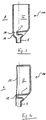
- Fig. 1 shows a receiving device according to the invention a first embodiment in a filling phase.
- the receiving device 100 has in its interior I a Fluidschwallum effetselement having a Umströmungsharm 1.
- the bypass body 1 is arranged within a transition region 3 of the receiving device 100 between an inflow channel 5 and a useful region 7 of the receiving device 100.
- the transition region 3 of the receiving device 100 allows a meaningful transition between the relatively small fluid cross section of the inflow channel 5 and the relatively large cross section of the receiving device 100, such as the manufacturability of the receiving device 100 and the inflow channel 5 in one piece, a good self-emptying of the receiving device 100 also at obliquely arranged arrangement of the receiving device 100, the integration of a Kanalver gleichventils directly at the transition of the inflow channel 5 in the receiving device and the like.
- measuring devices for detecting a water level of the fluids contained in the receiving device 100 may be provided. Such measuring devices can be configured optimized for this purpose of detection.
- the bypass body 1 is preferably disposed within the transition region 3, also to use the space of the transition region 3.
- the useful area 7 of the receiving device 100 can satisfy requirements, for example a favorable ratio between space requirement and filling volume of the receiving device 100, a favorable measurability of the filling volume of the receiving device 100 or the fluids contained therein or other sizes (such as by means of transparency of the fluids in the receiving device 100 ), a low wetted surface compared to the filling volume, good wetting and Entnetzungs , a good flow behavior of the fluids and the like.
- the fluid surge flowing into the receiving device 100 strikes a front 11 of the bypass body 1 and is divided into two partial fluid surge.
- the partial fluid bilges are guided past a right side flank 13 and a left side flank 15, respectively.
- the flow body 1 can, as in Fig. 1 shown to have an elliptical cross-section.
- the flow body 1 is, as in Fig. 1 shown disposed substantially symmetrically in the inflow zone of the fluid surge.
- both the width and the height (extension in the direction of flow in the direction of the double arrow) of the flow body 1 may be directed to give the Umströmungs stresses 1 as small as possible in all directions spatial dimension.
- These minimally small dimensions of the bypass body 1 can preferably contribute to ensuring the lowest possible loss of usable filling volume of the receiving device 100 and / or to reduce the surface of the receiving device 100 to be wiped and de-entangled.
- a smaller surface can advantageously lead to lower adhesion possibilities for small gas bubbles.
- a lesser surface area may generally reduce the chemical and / or physical reactivity of the fluids with the material of the receiver 100 and / or with the gas in the receiver. For example, this can advantageously lead to an improved haemocompatibility and / or reduced blood coagulation tendency through less air and less foreign surface.
- a smaller surface area, in relation to the maximum filling volume, advantageously allows the fluids to flow into and out of the receiving device 100 in a more complete and reproducible manner since smaller residual quantities can adhere to this surface.
- the accurate measurement of the filling volume based on the level can be facilitated.
- the exchange of fluids between the filling / emptying cycles can advantageously be more complete.
- the mixing of the fluid charges can, what can be sought procedurally in many cases, especially with regard to improved hemocompatibility by avoiding blood adhesion and reduction of blood residence time to foreign surfaces can be achieved.
- the minimum dimensions of the bypass body 1 can be determined experimentally and selected so that the desired effect of calming the flows and the level surface as well as the minimal generation and introduction of gas into the fluids flowing into the receiver 100 can just be achieved.
- the minimum possible dimensions may depend on the shape and / or the average flow velocity in the inflow passage 5, the composition and viscosity of the inflowing fluids, the material and the surface structure of the sidewalls of the inflow passage 5, the receiver 100 and / or the bypass body 1, of FIG the design of the transition region 3, of the geometric connection of the Umströmungs stressess 1 to the receiving device 100, of the possible pulsation and the permissible volume flow range of the inflowing fluids and / or of all geometric factors on the currents in the nearer and somewhat wider environment (to about depend on ten times the cross section of the inflow channel 5) of the Umströmungs stresses 1.
- the desired effect of the flow calming can already be achieved with surprisingly small dimensions of the flow body 1 in the range of sizes smaller than the mean flow cross section in the inflow channel 5.
- the bypass body 1 could be curved in all dimensions, such as a sphere or an ellipsoid.
- the joint and / or dead space free connection to the receiving device 100 and / or the In order to achieve cost-effective manufacturability from one piece with the receiving device 100, the flow-around body 1 in a particularly preferred embodiment can have only one flow cross-section curved in two spatial directions. For example, it may preferably have a substantially prismatic design, as described below in FIG 3 and 4 is shown.
- a flow calming of the fluid surge can take place.
- the mechanism of action of the flow calming can - compared to other solutions - rely more on a targeted self-surge extinction. Overall, it can represent a combination of several flow effects.
- a slowing down of the flow of fluid surge can be achieved a) by channel expansion of the inflow duct 5 between the Umströmungsterrorism 5 and the walls or side walls of the transition region 3 and / or b) by a division into at least two equal and each half as large opposite flowing partial flows or partial fluid surge and / or c) by a division of the respective Operafluidschwalle in at least two other partial fluid surge with opposite momentum or spin by adhesion to the Umströmungs endeavor 1 on one side and to the respective side wall of the receiving device 100 on the other side and / or d) by a collision and mutual extinction of the opposite equal flow and swirl pulses on the opposite side, ie the back 17 of the Umströmungs emotionss 1 and / or e) by meeting and extinguishing the opposite equal sized St Rung pulses in the areas between the UmströmungsAvem 1 and a side wall of the receiving device 100 right and left of the Umströmungs emotionss 1 and / or b
- the bypass body 1 may have a circular, elliptical, paraboloidal or Gothic pointed cross section.
- the bypass body 1 may have an asymmetrical cross section with respect to the sides facing and away from the inflow passage 5.
- the symmetrical design of the geometry on the right side flank 13 and the left side flank 15 may be essential to the proper functioning of the impulse division and self-extinction operations.
- Fig. 2 shows the receiving device 100 according to the invention in a discharge phase in which the fluids are shortly before the detachment from the flow body 1.
- the inflow channel 5 acts in this case as an outflow channel.
- the right-left symmetrical design of the Umströmungs emotionss 1 and / or the remaining receptacle 100 in conjunction with the gradual extension of the flow cross-section of the outflow channel before and behind the narrowest passage zone right and left of Umströmungs emotionss 1 help that the compact Zone of the main fluid as long as possible with the thin fluid zones of the residual wetting with the Umströmungs endeavor 1 and / or with the side walls of the receiving device 100 remains in contact.
- a maximum amount of residual liquid is entrained with the main flow, before it comes to the detachment and the whereabouts of residual films on the surfaces of the Umströmungs emotionss 1 and the side walls of the receiving device 100.
- Fig. 3 shows an embodiment of the receiving device according to the invention in longitudinal section, in which the receiving device 100, the inflow passage 5 and the bypass body 1 are injection-molded in one piece.
- the circulating body 1 is not connected to the front side with an opposite wall 19, but instead has a gap 21, which is sufficiently large for avoiding flow dead zones and / or air pockets, to the wall 19.
- Fig. 4 shows a further embodiment of the present receiving device 100 in longitudinal section, in which the overall arrangement is carried out in the typical cassette design.
- channels such as an inflow channel 5, and / or chambers in an injection molded part can be made substantially open on one side.
- the foil as in Fig. 4 shown by welding and / or pressing on an end face 25 of the Umströmungs stressess 1 are applied with direct contact to this. With such an arrangement, a gap can be deliberately avoided.
- Fig. 5 shows a front view of an external functional device according to the invention, which at the surface, on the in Fig. 5 is provided with a cover 23 is provided.
- the external functional device is here exemplarily designed as a blood treatment cassette 1000 with chambers, channels, valves and the like.
- the cover device 23 covers a front side of the blood treatment cassette 1000. It is exemplified as a film.
- the blood treatment cassette 1000 may be at least the same as in Fig. 5 shown front to a blood treatment device (in Fig. 5 not shown).
- the blood treatment cassette 1000 has the receiving device 100 according to the invention.
- the receiving device 100 extends from the in Figure 5 shown front view backwards in the plane of the drawing Fig. 5 into it.
- the course of the wall 19 of the receiving device 100 away from the viewer is indicated by the lines shown in the radial direction.
- the bypass body 1 extends from its base toward the viewer of the Fig. 1 to.
- the receiving device 100 has the bypass body 1.
- Figure 5 are particularly well from the flow body 1, the end face 25 and a lower lying in the drawing plane saddle-shaped connecting portion 12 between the Umströmungsharm 1 and the wall 19 to recognize.
- the receiving device 100 has a phantom valve 27 at its lower end, ie at the inflow region.
- the circulating body 1 is flown in the receiving device 100 via the phantom valve 27, wherein blood from the underlying chamber (eg a venous blood chamber, as in the filed by the applicant of the present application to the DPMA on June 10, 2009 application 10 2009 024 465 A1 with the title "air separator, external functional device , blood circulation and treatment device " ) is introduced into the receiving device 100 through the phantom valve 27 formed by the cover device 23 and a web section.
- the underlying chamber eg a venous blood chamber, as in the filed by the applicant of the present application to the DPMA on June 10, 2009 application 10 2009 024 465 A1 with the title "air separator, external functional device , blood circulation and treatment device "
- Fig. 6 shows the blood treatment cassette 1000 of Fig. 5 , wherein the covering device 23 on the left edge of the blood treatment cassette 1000 as well as above and below erförend cut and can be seen unfolded to the right.
- Fig. 6 shows the elements to be recognized in more detail in the interior of the blood treatment cassette 1000 after the foil has been cut open.
- Fig. 7 shows the blood treatment cassette 1000 from its back.
- the blood treatment cassette 1000 is coupled to the blood treatment device, a viewer will look at this rear side upon opening a door of the blood treatment device for removing the blood treatment cassette 1000.
Landscapes
- Health & Medical Sciences (AREA)
- Heart & Thoracic Surgery (AREA)
- Vascular Medicine (AREA)
- Biomedical Technology (AREA)
- Engineering & Computer Science (AREA)
- Anesthesiology (AREA)
- Cardiology (AREA)
- Hematology (AREA)
- Life Sciences & Earth Sciences (AREA)
- Animal Behavior & Ethology (AREA)
- General Health & Medical Sciences (AREA)
- Public Health (AREA)
- Veterinary Medicine (AREA)
- External Artificial Organs (AREA)
- Physical Or Chemical Processes And Apparatus (AREA)
Description
Die vorliegende Erfindung betrifft eine Aufnahmeeinrichtung zum Aufnehmen von medizinischen Fluiden gemäß dem Oberbegriff des Anspruchs 1. Sie betrifft ferner eine externe Funktionseinrichtung gemäß Anspruch 14 sowie eine medizinische Behandlungsvorrichtung gemäß Anspruch 15.The present invention relates to a receiving device for receiving medical fluids according to the preamble of
Verschiedene Vorrichtungen, wie beispielsweise Behandlungsvorrichtungen der Medizintechnik, weisen Aufnahmeeinrichtungen zum vorübergehenden Aufnehmen von Fluiden auf. Diese werden während des Betriebs der Vorrichtung i.a.R. mehrfach mit Fluid befüllt und auch wieder entleert. Beim Befüllen und Entleeren üblicherweise auftretende Strömungsphänomene werden regelmäßig mittels geeigneter baulicher Maßnahmen beeinflusst. Zu ihnen zählen Behälterwanddüsen, Prallwände sowie geometrische Ausgestaltungen von Bauelementen z.B. in Tauchrohrformen, Diffusorformen und dergleichen.Various devices, such as medical device treatment devices, have receiving means for temporarily receiving fluids. These are repeatedly filled with fluid during operation of the device iaR and also emptied again. Flow phenomena that usually occur during filling and emptying are regularly influenced by suitable structural measures. These include container wall nozzles, baffles and geometric configurations of components, for example in dip tube shapes, diffuser shapes and the like.
Die
Die
Die
Die
Eine Aufgabe der vorliegenden Erfindung ist, eine weitere Aufnahmeeinrichtung zum Aufnehmen von medizinischen Fluiden, insbesondere Blut, mit einer Einrichtung zum Beeinflussen einer Fluidströmung anzugeben.An object of the present invention is to provide a further receiving device for receiving medical fluids, in particular blood, with a device for influencing a fluid flow.
Die erfindungsgemäße Aufgabe wird durch eine Aufnahmeeinrichtung zum Aufnehmen eines oder mehrerer medizinischer Fluide mit den Merkmalen des Anspruchs 1 gelöst.The object according to the invention is achieved by a receiving device for receiving one or more medical fluids having the features of
Die erfindungsgemäße Aufnahmeeinrichtung weist eine Einströmungsöffnung auf, durch welche wenigstens ein medizinisches Fluid in ein Inneres der Aufnahmeeinrichtung einführbar oder einbringbar ist. Sie weist ferner wenigstens ein Fluidschwallumleitungselement zum Umleiten des Fluidschwalls des einströmenden Fluids auf.The receiving device according to the invention has an inflow opening, through which at least one medical fluid into an interior of the receiving device is insertable or einbringbar. It also has at least one fluid flow bypass element for diverting the fluid surge of the inflowing fluid.
Der Begriff "Einströmungsöffnung", wie er hierin verwendet wird, bezeichnet eine Öffnung oder eine Aussparung - z. B. in einer Seite bzw. Seitenfläche bzw. Seitenwand der Aufnahmeeinrichtung - durch welche ein Fluid in das geschlossene oder zur Umgebung offene Innere der Aufnahmeeinrichtung einströmen, eintreten oder einfließen kann.The term "inflow port" as used herein refers to an opening or recess - e.g. B. in a side or side surface or side wall of the receiving device - through which a fluid flow into the closed or open to the environment interior of the receiving device, can enter or flow.
Ein "Fluid" im Sinne der vorliegenden Erfindung schließt jede medizinische Flüssigkeit und/oder jedes medizinische Gas und/oder jedes Flüssigkeits-Gas-Gemisch (z.B. Gasblasen in Flüssigkeit, Schaum, insbesondere Blut mit Luftblasen, Blutschaum) ein. Insbesondere kann es sich um Blut in einem extrakorporalen Blutkreislauf handeln.For the purposes of the present invention, a "fluid" includes any medical fluid and / or medical gas and / or liquid-gas mixture (e.g., gas bubbles in fluid, foam, especially blood with air bubbles, blood foam). In particular, it may be blood in an extracorporeal blood circulation.
Das "Fluid" ist hier und im Folgenden gleichbedeutend als medizinisches Fluid zu verstehen.The "fluid" is to be understood here and in the following synonymous as a medical fluid.
Ein "Inneres der Aufnahmeeinrichtung" bezeichnet ein Volumen bzw. einen Rauminhalt der Aufnahmeeinrichtung, welches zum vollständigen oder teilweise Befüllen mit Fluiden und Aufnehmen derselben geeignet und vorgesehen ist.An "interior of the receiving device" denotes a volume or a volume of the receiving device which is suitable and intended for full or partial filling with fluids and receiving them.
Ein "Fluidschwallumleitungselement" bezeichnet einen Körper, welcher zum Beeinflussen eines Fluidschwalls, insbesondere zum Umleiten eines auf ihn auftreffenden Fluidschwalls, geeignet ist. Dieser Körper kann ein um- und/oder überströmbares Element sein.A "fluid flow diverting element" refers to a body which is suitable for influencing a fluid surge, in particular for diverting a fluid surge impinging on it. This body may be an umströmungsund and / or overflow element.
Dabei kann das Fluidschwallumleitungselement erfindungsgemäß auch als ein Fluidkontaktelement verstanden werden, welches in der Aufnahmeeinrichtung mit dem Ziel vorgesehen ist, von dem in das Innere der Aufnahmeeinrichtung einströmenden Fluidschwall getroffen zu werden bzw. mit diesem in Kontakt zu treten. Dieser Kontakt ist konstruktiv absichtlich herbeigeführt, damit der Fluidschwall auf beabsichtigte Weise beeinflusst wird. Dies kann ein Abschwächen des Impulses des Fluidschwalls bedeuten, ein Auslöschen des Impulses des Fluidschwalls im Sinne einer Übertragung. Es kann ferner insbesondere ein gezieltes Aufteilen des Fluidschwalls in wenigstens zwei nachverfolgbare Fluidteilschwalle oder viele kleine Fluidteilschwalle bedeuten, wie unten stehend detaillierter ausgeführt wird.In this case, the fluid flow bypass element according to the invention can also be understood as a fluid contact element which is provided in the receiving device with the aim of flowing into the interior of the receiving device Fluid surge to be met or to get in touch with this. This contact is deliberately designed to affect the surge of fluid in an intended manner. This may mean weakening the pulse of the fluid surge, canceling out the pulse of fluid surge in the sense of transmission. In particular, it can also mean a deliberate division of the fluid surge into at least two traceable fluid component surge or many small fluid partial surge, as will be explained in more detail below.
Das Fluidschwallumleitungselement weist hierzu erfindungsgemäß wenigstens einen Umströmungskörper auf, welcher ausgelegt und/oder vorgesehen und geeignet ist, den Fluidschwall in wenigstens zwei Teilströme aufzuteilen. Die Teilströme liegen nach ihrer Aufteilung - zumindest vorübergehend - körperlich getrennt voneinander, also ohne Kontakt zueinander, vor.According to the invention, the fluid surge bypass element has at least one bypass body which is designed and / or provided and is suitable for dividing the fluid surge into at least two partial flows. The sub-streams are after their division - at least temporarily - physically separated from each other, ie without contact with each other before.
Der Begriff "Fluidschwall" bezeichnet eine Menge oder ein Volumen des in die Aufnahmeeinrichtung eingebrachten oder einströmenden Fluids.The term "fluid surge" refers to a quantity or volume of the fluid introduced or entering the receiving device.
Der Fluidschwall kann ein kontinuierlicher und/oder konstanter (z.B. mit einer konstanten Geschwindigkeit einströmender) Fluidschwall oder ein zu einem bestimmten Zeitpunkt und/oder nur über einen begrenzten, bestimmten Zeitraum in die Aufnahmeeinrichtung einströmender Fluidschwall sein.The fluid surge may be a continuous and / or constant (e.g., inflowing at a constant rate) fluid surge, or a fluid surge flowing into the receiver at a particular time and / or only for a limited, predetermined period of time.
Der Fluidschwall kann einen Impuls übertragen. Der Fluidschwall kann dergestalt sein, dass sein Einströmen in die Aufnahmeeinrichtung ohne Vorsehen eines wie oben beschriebenen Fluidschwallumleitungselements zu Turbulenzen und/oder zu Gaseinschlüssen (insbesondere von Luft) in das einströmende Fluid (insbesondere eine Flüssigkeit) oder in einem Fluid, in das ein weiteres Fluid einströmen soll (insbesondere Blut) führen würde.The fluid surge can transmit a pulse. The fluid surge may be such that its inflow into the receiving device without providing a fluid surge diverter as described above results in turbulence and / or gas inclusions (especially of air) in the incoming fluid (particularly a liquid) or in a fluid into which another fluid should flow (especially blood) would lead.
Der Begriff "Teilfluidschwall" bezeichnet einen durch Aufteilen des ursprünglich in die Aufnahmeeinrichtung einströmenden Fluidschwalls mittels des Umströmungskörpers erhaltenen Teilstrom oder ein Teilvolumen des ursprünglich eingeströmten gesamten Fluidschwalls. Der Teilfluidschwall ist ein Anteil des Fluidschwalls.The term "partial fluid surge" refers to a partial flow obtained by dividing the fluid surge initially flowing into the receiving device by means of the bypass body or a partial volume of the total fluid surge originally flowed in. The partial fluid surge is a component of the fluid surge.
Mittels der Aufteilung des Fluidschwalls in Teilfluidschwalle kann das Auftreten unerwünschter Strömungsphänomene vorteilhaft verhindert werden.By means of the division of the fluid surge into partial fluid surge, the occurrence of undesired flow phenomena can be advantageously prevented.
Vorteilhafte Weiterentwicklungen der vorliegenden Erfindung sind jeweils Gegenstand der Unteransprüche.Advantageous developments of the present invention are the subject of the dependent claims.
Die Gesamtheit aller Anteile der mittels des Umströmungskörpers erhalten Teilfluidschwalle, welche nach Aufteilung des Fluidschwalls in die Teilfluidschwalle weiter in das Innere der Aufnahmeeinrichtung verbleiben, können sich in einer bevorzugten Ausführungsform der Erfindung im Wesentlichen zu 100 % des gesamten Fluidschwalls addieren. Dies bedeutet, dass alle Teilfluidschwalle weiterhin in die Aufnahmeeinrichtung eintreten oder zunächst in dieser verbleiben.The entirety of all portions of the partial fluid bumps obtained by means of the bypass body, which remain in the interior of the receiving device after splitting the fluid surge into the partial fluid surge, may add up to substantially 100% of the total fluid surge in a preferred embodiment of the invention. This means that all Teilfluidschwalle continue to enter the receiving device or initially remain in this.
Die Anteile des Strömungsvolumens oder der Strömungsmenge des einzelnen Teilfluidschwalls können jeweils gleich oder verschieden voneinander sein.The proportions of the flow volume or the flow rate of the individual Teilfluidschwalls may each be the same or different from each other.
In der Erfindung ist der Umströmungskörper in einem Einströmungsbereich des Fluidschwalls angeordnet, und im Ausströmungsbereich eines Phantomventils in einer Blutkassette zur extrakorporalen Blutbehandlung.In the invention, the bypass body is disposed in an inflow area of the fluid surge, and in the outflow area of a phantom valve in a blood cassette for extracorporeal blood treatment.
Der Begriff "Phantomventil", wie er hierin verwendet wird, bezeichnet ein Element mit einer mittels Aktor erreichbaren Aktor-Fläche (hier beispielsweise eine Aktor-Membran), welches die Funktion eines Ventils übernehmen kann.The term "phantom valve", as used herein, refers to an element with an actuator surface achievable by means of an actuator (here, for example, an actuator membrane), which can assume the function of a valve.
Die Aktor-Membran ist unter Aufbringung einer Kraft hierauf, z.B. einer Druckkraft, in eine Richtung bewegbar, ausdehnbar bzw. wölbbar oder dergleichen. Durch das Bewegen oder Ausdehnen der Aktor-Membran kann sich diese an ein Element, wie eine Abdichtungseinrichtung, etwa einen Steg, anlegen oder von diesem entfernen. Die Aktor-Membran kann somit beispielsweise eine Abdichtung bewirken bzw. verstärken oder beenden bzw. verringern.The actuator membrane is applied thereto by applying a force thereto, e.g. a compressive force, movable in one direction, expandable, or the like. By moving or expanding the actuator membrane, it can attach to or remove from an element, such as a sealing device, such as a web. The actuator membrane can thus effect, for example, a seal or strengthen or terminate or reduce.
Wenn die Kraft auf die Aktor-Membran aufgehoben wird, kann diese in beispielsweise eine Grundposition, z.B. einen nicht gewölbten Zustand, zurückkehren.When the force on the actuator membrane is removed, it may be brought into, for example, a home position, e.g. a non-curved state, return.
Der Begriff "Einströmungsbereich" bezeichnet den Bereich der Aufnahmeeinrichtung, in welchem sich der Fluidschwall unmittelbar nach Einströmen oder Einfließen in die Aufnahmeeinrichtung befindet. Der Einströmungsbereich kann dabei einen aufnahmeeinrichtungsseitigen Bereich um die Einströmungsöffnung herum in räumlichem Bezug zu dieser ausbilden, in welchem sich das durch die Einströmungsöffnung einströmende Fluid in der Aufnahmeeinrichtung auszubreiten und die Aufnahmeeinrichtung zu füllen beginnt.The term "inflow region" designates the region of the receiving device in which the fluid surge is located immediately after flowing into or flowing into the receiving device. In this case, the inflow region can form a receptacle-side region around the inflow opening in spatial relation to it, in which the fluid flowing in through the inflow opening begins to spread in the receptacle and the receptacle begins to fill.
In einer weiteren bevorzugten Ausführungsform ist der Umströmungskörper zentral (oder in einem zentralen Bereich) im Einströmungsbereich des Fluids, bezogen auf eine Mittelachse der Einströmungsöffnung oder der Einströmungsrichtung, angeordnet.In a further preferred embodiment, the bypass body is arranged centrally (or in a central region) in the inflow region of the fluid, with respect to a central axis of the inflow opening or the inflow direction.
Die "Mittelachse" bezeichnet dabei z.B. diejenige Achse, die auf einem mittleren Bereich oder einem Mittelpunkt des Querschnitts der Einströmungsöffnung oder der Einströmungsrichtung, wie beispielsweise dem Kreismittelpunkt einer Einströmungsöffnung mit kreisförmigem Querschnitt, senkrecht steht. Die Mittelachse kann parallel zu einer Hauptströmungseinrichtung des gesamten Fluidschwalls vor dessen Aufteilung in Teilfluidschwalle verlaufen.In this case, the "center axis" designates, for example, that axis which is perpendicular to a central region or a center point of the cross section of the inflow opening or the inflow direction, such as, for example, the circular center of an inflow opening with a circular cross section. The central axis can run parallel to a main flow device of the entire fluid surge prior to its division into Teilfluidschwalle.
Die Begriffe "zentral" und "mittig" werden in der vorliegenden Erfindung gleichbedeutend bzw. austauschbar verwendet. Sie sollen jeweils eine Anordnung einer Komponente in einem mittleren Bereich bzw. der Mitte eines Bezugssystems bzw. einer Bezugskomponente bezeichnen. Dabei ist eine zentrale oder mittige Anordnung bevorzugt derart definiert, dass der Formmittelpunkt, z.B. der Kreismittelpunkts des Querschnitts einer Komponente, auf einer Mittelachse oder einem Mittelpunkt der Bezugskomponente angeordnet ist. Formmittelpunkt, Mittelachse oder Mittelpunkt können wie allgemein üblich geometrisch bestimmt oder näherungsweise ermittelt werden.The terms "central" and "centered" are used in the present invention to be synonymous or interchangeable. They are each intended to denote an arrangement of a component in a middle region or the center of a reference system or a reference component. In this case, a central or central arrangement is preferably defined such that the center of shape, e.g. the circle center point of the cross section of a component, is arranged on a central axis or a center of the reference component. The center of the form, the central axis or the center can, as is generally customary, be geometrically determined or approximately determined.
Der Begriff "Querschnitt" kann, wie vorliegend verwendet, einen Querschnitt senkrecht zu einer Einströmungsrichtung oder parallel zu dieser verstanden werden. Beim "Querschnitt" kann es sich im Rahmen der Diskussion der vorliegenden Erfindung ungeachtet weiterer Merkmale desselben vorzugsweise um den Querschnitt maximalen Durchmessers oder maximaler Abmessungen handeln.As used herein, the term "cross-section" may be understood to mean a cross section perpendicular to or parallel to an inflow direction. The "cross section" in the discussion of the present invention, regardless of further features thereof, may preferably be the cross section of maximum diameter or dimensions.
Die Einströmungsöffnung kann beispielsweise in einem Flächeninneren oder einer Mitte einer Seite bzw. Seitenfläche bzw. Seitenwand der Aufnahmeeinrichtung angeordnet sein. Sie kann jedoch auch in einem Randbereich der Seite oder einer Begrenzung der Aufnahmeeinrichtung angeordnet sein.The inflow opening may be arranged, for example, in a surface interior or a middle of a side or side surface or side wall of the receiving device. However, it can also be arranged in an edge region of the side or a boundary of the receiving device.
Die Einströmungsöffnung kann sich über eine im Wesentlichen gesamte Länge einer Seite der Aufnahmeeinrichtung erstrecken. Die Einströmungsöffnung kann sich unabhängig hiervon über eine im Wesentlichen gesamte Breite der Seite der Aufnahmeeinrichtung erstrecken. Sie kann daher verschiedene räumliche Ausgestaltungen annehmen.The inflow opening may extend over a substantially entire length of one side of the receiving device. Irrespective of this, the inflow opening may extend over a substantially entire width of the side of the receiving device. It can therefore assume different spatial configurations.
Vorzugsweise ist die Einströmungsöffnung jedoch im Wesentlichen zentriert in einer Begrenzungsfläche der Aufnahmeeinrichtung vorgesehen, d.h. der Mittelpunkt (beispielsweise der Kreismittelpunkt einer Einströmungsöffnung mit kreisförmigem Querschnitt) der Einströmungsöffnung kann auf halber Länge und/oder halber Breite der Seitenfläche der Aufnahmeeinrichtung angeordnet sein.Preferably, however, the inflow opening is provided substantially centered in a boundary surface of the receiving device, ie, the center (for example, the circular center of an inflow opening with a circular Cross-section) of the inflow opening may be arranged at half the length and / or half the width of the side surface of the receiving device.
Die Einströmungsöffnung kann einen kreisförmigen oder elliptischen Querschnitt aufweisen, sie kann jedoch auch jeden anderen Querschnitt aufweisen, der zum Zwecke der vorliegenden Erfindung geeignet scheint.The inflow port may have a circular or elliptical cross-section, but it may also have any other cross-section which seems suitable for the purpose of the present invention.
Es können auch mehrere gleichartig oder verschiedenartig ausgestaltete Einströmungsöffnungen in der Aufnahmeeinrichtung vorgesehen sein. Die Ausgestaltung derselben kann jeweils strömungsoptimiert und für den angestrebten Zweck geeignet ausgewählt werden.It can also be provided in the receiving device a plurality of identically or differently configured inflow openings. The configuration of the same can each be optimized for flow and suitably selected for the intended purpose.
Falls mehrere Einströmungsöffnungen in einer oder mehreren Seitenwänden oder Seitenflächen der Aufnahmeeinrichtung vorgesehen sind, kann wenigstens eine der Einströmungsöffnungen dabei erfindungsgemäß ein Fluidschwallumleitungselement bzw. einen Umströmungskörper im Einströmungsbereich des Fluidschwalls aufweisen.If a plurality of inflow openings are provided in one or more side walls or side faces of the receiving device, at least one of the inflow openings can have a fluid flow diverting element or a circulating body in the inflow region of the fluid swell.
Der Umströmungskörper kann bevorzugt symmetrisch ausgestaltet sein. Der Umströmungskörper kann bevorzugt symmetrisch bezogen auf die Mittelachse der Einströmungsöffnung ausgestaltet bzw. angeordnet sein.The bypass body may preferably be designed symmetrically. The bypass body may preferably be configured or arranged symmetrically with respect to the central axis of the inflow opening.
Dies umfasst, dass ein Querschnitt des Umströmungskörpers in einer Ebene senkrecht zur Einströmungsrichtung des in die Aufnahmeeinrichtung eingebrachten Fluidschwalls zu der Mittelachse der Einströmungsöffnung symmetrisch angeordnet bzw. vorgesehen sein kann. Bevorzugt ist eine Symmetrie in der näheren Umgebung des Fluidschwallelements vorgesehen. Die gesamte Einrichtung muss hingegen nicht zwingend symmetrisch sein.This comprises that a cross-section of the bypass body can be symmetrically arranged or provided in a plane perpendicular to the inflow direction of the fluid surge introduced into the receiving device relative to the central axis of the inflow opening. Preferably, a symmetry is provided in the vicinity of the fluid flow element. By contrast, the entire device does not necessarily have to be symmetrical.
Der Umströmungskörper kann allgemein eine Front oder Prallfläche, auf welche der einströmende Fluidschwall oder ein wesentlicher Anteil hiervon auftrifft, und eine Rückseite, an welcher die Teilfluidschwalle zusammengeführt werden können, aufweisen.The bypass body may generally include a front or baffle on which the incoming fluid surge or a substantial portion thereof impinges, and a Rear side, at which the Teilfluidschwalle can be brought together have.
Ein erneutes Zusammenführen der aufgeteilten Teilfluidschwalle an einem rückwärtigen Abschnitt des Umströmungskörpers oder einem stromabwärts gelegenen Abschnitt desselben ist von der Erfindung umfasst. Die Erfindung ist jedoch nicht auf ein erneutes Zusammenführen beschränkt; anders formuliert ist dies keine erforderliche Wirkung einer jeden Ausführungsform der Erfindung.Rejoining the divided partial fluid surge at a rear portion of the bypass body or a downstream portion thereof is contemplated by the invention. However, the invention is not limited to a re-merging; In other words, this is not a required effect of each embodiment of the invention.
Der Umströmungskörper kann ferner eine linke und eine rechte Seitenflanke aufweisen, an welcher jeweils ein Teilfluidschwall entlang strömen kann.The bypass body may further comprise left and right side flanks, along which a partial fluid surge can flow.
Ein symmetrisch ausgestalteter Umströmungskörper kann derart ausgestaltet sein, dass die geometrische Form bzw. Ausgestaltung der linken und der rechten Seitenflanke spiegelsymmetrisch zur Mittelachse der Einströmungsöffnung vorgesehen ist.A symmetrically configured flow-around body can be designed such that the geometric shape or configuration of the left and the right side flank is provided mirror-symmetrically to the central axis of the inflow opening.
Die geometrische Form der Front und der Rückseite des Umströmungskörpers können ebenfalls spiegelsymmetrisch zu einer Achse senkrecht zu der Mittelachse der Einströmungsöffnung, d.h. senkrecht zu der Strömungsrichtung des in die Aufnahmeeinrichtung einströmenden Fluidschwalls, angeordnet sein. Die Erfindung ist jedoch nicht hierauf beschränkt.The geometric shape of the front and back of the bypass body may also be mirror-symmetrical to an axis perpendicular to the center axis of the inflow port, i. be arranged perpendicular to the flow direction of the flowing into the receiving device fluid surge. However, the invention is not limited thereto.
Beispielsweise kann der Querschnitt des Umströmungskörpers kreisförmig sein, wobei in diesem Fall der Umströmungskörper selbst rotationssymmetrisch ausgestaltet ist.For example, the cross section of the Umströmungskörpers be circular, in which case the Umströmungskörper itself is configured rotationally symmetrical.
Alternativ kann der Querschnitt des Umströmungskörpers elliptisch ausgestaltet sein, wobei in diesem Fall jeweils die linke und rechte Seitenflanke des Umströmungskörpers sowie die Front und die Rückseite des Umströmungskörpers zueinander symmetrisch ausgestaltet sind.Alternatively, the cross section of the bypass body may be configured elliptical, in which case in each case the left and right side flanks of the bypass body and the front and the back of the bypass body are symmetrical to one another.
Der Querschnitt des Umströmungskörpers kann auch paraboloid oder gotisch spitz oder anders ausgestaltet sein.The cross section of the Umströmungskörpers may also be paraboloid or gothic pointed or designed differently.
Der Querschnitt des Umströmungskörpers kann sich entlang der Höhe oder Tiefe des Umströmungskörpers verändern. Beispielsweise kann die Querschnittsfläche über die Höhe des Umströmungskörpers variieren, z.B. können sich die Querschnittsfläche oder ein Durchmesser derselben über die Höhe verjüngen, d.h. kleiner werden oder abnehmen. Der Querschnitt des Umströmungskörpers kann jedoch entlang der Höhe oder Tiefe des Umströmungskörpers auch konstant bleiben.The cross-section of the bypass body may vary along the height or depth of the bypass body. For example, the cross-sectional area may vary over the height of the bypass body, e.g. For example, the cross sectional area or a diameter thereof may be tapered over the height, i. get smaller or lose weight. However, the cross-section of the bypass body may also remain constant along the height or depth of the bypass body.
Die Querschnittsfläche bzw. der Durchmesser können über die Höhe des Umströmungskörpers mehrfach abnehmen und zunehmen (oder umgekehrt), um ein für die jeweilige Anwendung und das jeweils eingesetzte Fluid optimierte Fluidschwallumleitung zu erreichen.The cross-sectional area or the diameter can decrease and increase several times over the height of the flow body and (or vice versa) in order to achieve a fluid flow diversion optimized for the respective application and the respectively used fluid.
Der Umströmungskörper kann ausgestaltet sein, um den ursprünglich in die Aufnahmeeinrichtung eingebrachten Fluidschwall in mehr als zwei Teilfluidschwalle aufzuteilen.The bypass body may be configured to divide the fluid surge initially introduced into the receiver into more than two partial fluid jets.
Der Umströmungskörper kann beispielsweise in einem zentralen Bereich eine Durchtrittsöffnung zur Durchleitung eines dritten Teilfluidschwalls aufweisen.The flow-around body can, for example, have a passage opening for the passage of a third partial fluid surge in a central area.
Die Durchtrittsöffnung kann sich beispielsweise von der Front bis zur Rückseite des Umströmungskörpers erstrecken.The passage opening may extend, for example, from the front to the rear of the bypass body.
In einer weiter bevorzugten Ausführungsform ist der Umströmungskörper mit dem 0,4fachen bis 2fachen des Durchmessers der Einströmungsöffnung oder des Strömungskanaldurchmessers von der Einströmungsöffnung beabstandet im Einströmungsbereich der Aufnahmeeinrichtung angeordnet.In a further preferred embodiment, the Umströmungskörper with the 0.4 times to 2 times the diameter of the inflow opening or the flow channel diameter of the inflow opening spaced in the inflow region of the receiving device is arranged.
Dieser Abstand kann sich vorzugsweise auf eine Entfernung zwischen der Einströmungsöffnung, beispielsweise der Mündung der Einströmungsöffnung in der Seitenfläche oder Seitenwand der Aufnahmeeinrichtung, und der Front (z.B. des am weitesten strömungsaufwärts des Fluidschwalls oder des einen Hauptaufprallpunktes des Fluidschwalls) gelegenen Punktes des Umströmungskörpers beziehen.This distance may preferably refer to a distance between the inflow port, for example the mouth of the inflow port in the side face or side wall of the take-up device, and the front (e.g., the farthest upstream of the fluid surge or the one main impact point of fluid surge) point of the bypass body.
In einer weiteren bevorzugten Ausführungsform kann ein Durchmesser des Umströmungskörpers in einer Ebene senkrecht zur Mittelachse oder senkrecht zur Hauptaufprallrichtung des Fluidschwalls auf den Umströmungskörper der Einströmungsöffnung 0,4 bis 1,2-mal so groß wie der Durchmesser der Einströmungsöffnung oder des Strömungskanaldurchmessers sein.In another preferred embodiment, a diameter of the bypass body in a plane perpendicular to the central axis or perpendicular to the main impingement direction of the fluid surge on the inflow body of the inflow port may be 0.4 to 1.2 times the diameter of the inflow port or the flow channel diameter.
Dieser Durchmesser kann bevorzugt der maximale Durchmesser des Umströmungskörpers sein, beispielsweise der längere Durchmesser eines Umströmungskörpers mit elliptischem Querschnitt, wie er in
In einer weiter bevorzugten Ausführungsform ist das Fluidschwallumleitungselement stoffschlüssig mit der Aufnahmeeinrichtung ausgestaltet.In a further preferred embodiment, the Fluidschwallumleitungselement cohesively configured with the receiving device.
Das Fluidumschwallumleitungselement bzw. der Umströmungskörper kann während der Herstellung der Aufnahmeeinrichtung gemeinsam mit dieser ausgestaltet bzw. ausgeformt sein. Dies kann beispielsweise mittels Spritzgießen der Aufnahmeeinrichtung erreicht werden. Die Aufnahmeeinrichtung kann beispielsweise als prismatische Spritzgusskammer ausgestaltet sein.During the production of the receiving device, the fluid bypass diversion element or the bypass body may be designed or shaped together with it. This can be achieved for example by means of injection molding of the receiving device. The receiving device may be configured, for example, as a prismatic injection molding chamber.
Die Aufnahmeeinrichtung kann in Kassettenbauform oder als Teil einer solchen ausgestaltet sein. Sie kann beispielsweise eine externe Funktionseinrichtung oder Teil einer externen Funktionseinrichtung sein. Die Aufnahmeeinrichtung kann vorzugsweise stoffschlüssig in die externe Funktionseinrichtung integriert sein.The receiving device may be configured in cassette form or as part of such. It may be, for example, an external functional device or part of an external functional device. The receiving device may preferably be integrally integrated into the external functional device.
In einer weiter bevorzugten Ausführungsform ist die Aufnahmeeinrichtung an der Einströmungsöffnung mit einem Einströmungskanal verbunden. Sie kann alternativ mit mehreren Einströmungskanälen verbunden sein. Der Anschlusskanal bzw. Einströmungskanal kann einstückig in das untere Ende der Aufnahmeeinrichtung integriert sein.In a further preferred embodiment, the receiving device is connected to the inflow opening with an inflow channel. It may alternatively be connected to a plurality of inflow channels. The connection channel or inflow channel can be integrally integrated in the lower end of the receiving device.
Der Einströmungskanal kann ein geschlossener, halboffener Kanal oder eine Leitung sein. Er kann in eine externe Funktionseinrichtung integriert sein. Ein solcher Kanal bzw. eine solche Leitung kann während der Herstellung der externen Funktionseinrichtung, beispielsweise mittels Spritzgießen, ausgestaltet bzw. ausgeformt werden.The inflow channel may be a closed, semi-open channel or conduit. It can be integrated in an external functional device. Such a channel or such a line can be designed or formed during the production of the external functional device, for example by means of injection molding.
In einer weiter bevorzugten Ausführungsform kann die Einströmungsöffnung geeignet und vorgesehen sein, in das Innere der Aufnahmeeinrichtung eingeströmte Fluide ausströmen zu lassen.In a further preferred embodiment, the inflow opening may be suitable and provided to allow fluids flowed into the interior of the receiving device to flow out.
Dies kann beispielsweise von Vorteil sein, um einen möglichst vollständigen Austausch von Fluiden beim Befüllen oder Entleeren der Aufnahmeeinrichtung zu bewerkstelligen.This may be advantageous, for example, to accomplish the most complete exchange of fluids when filling or emptying the receiving device.
Dies kann insbesondere von Vorteil sein, wenn die Aufnahmeeinrichtung Teil einer externen Funktionseinrichtung, wie beispielsweise einer Blutkassette oder Blutbehandlungskassette ist, und eine platzsparende Anordnung der einzelnen Komponenten der Blutkassette wesentlich oder erforderlich oder gewünscht ist.This may be particularly advantageous if the receiving device is part of an external functional device, such as a blood cassette or blood treatment cassette, and a space-saving arrangement of the individual components of the blood cassette is essential or required or desired.
Zur Einstellung einer Strömungsrichtung der in die Aufnahmeeinrichtung ein- oder ausströmenden Fluide kann die Einströmungs- bzw. Ausströmungsöffnung beispielsweise mit einem oder mehreren verschiedenen und/oder verschiedenartig bzw. unterschiedlich ausgestalteten oder vorgesehenen Vorsprüngen, Einrückungen, Strömungs- bzw. Umströmungselementen und dergleichen in der Öffnung selbst, d.h. in der Durchtrittsfläche derselben, versehen sein.In order to set a flow direction of the fluids entering or leaving the receiving device, the inflow or outflow opening can be provided, for example, with one or more different and / or different or differently configured or provided projections, indentations, Flow or Umströmungselementen and the like in the opening itself, ie in the passage area thereof, be provided.
Zu einer vollständigen Entleerung der Aufnahmeeinrichtung über das Auslaufen der Flüssigkeit nach unten (Schwerkraftentleerung), kann der Ablaufkanal bzw. der Ausströmungskanal am geodätisch tiefsten Punkt der Aufnahmeeinrichtung angeordnet sein.For a complete emptying of the receiving device via the leakage of the liquid downwards (gravity drainage), the drainage channel or the outflow channel can be arranged at the geodetically lowest point of the receiving device.
Die Seitenwände der Aufnahmeeinrichtung können in der Umgebung des Ablaufkanals bzw. des Ausströmungskanals eine gewisse Mindestschräge aufweisen, welche das Ausströmen der in der Aufnahmeeinrichtung vorhandenen Fluide erleichtern können. Somit kann vorteilhaft auch eine nicht vollständig vertikal ausgerichtete Aufnahmeeinrichtung leerlaufen.The side walls of the receiving device may have a certain minimum slope in the vicinity of the drainage channel or the outflow channel, which may facilitate the outflow of the fluids present in the receiving device. Thus, advantageously, a not completely vertically aligned receiving device idle.
Ferner können mit einer solchen Anordnung Strömungstotzonen vorteilhaft verringert oder gar vermieden werden.Furthermore, flow stagnation zones can advantageously be reduced or even avoided with such an arrangement.
In einer weiteren bevorzugten Ausführungsform ist die Aufnahmeeinrichtung in einem extrakorporalen Blutkreislauf angeordnet.In a further preferred embodiment, the receiving device is arranged in an extracorporeal blood circulation.
Das Fluidschwallumleitungselement, insbesondere ein Blutschwallumleitungselement oder Blutschwallelement, kann zum Erzielen einer Strömungsverlangsamung, zum Erzeugen einer Turbulenz und/oder Umleiten eines in einer Single-Needle-Kammer befindlichen Blutschwalls oder zum Auslöschen des Impulses des Blutschwalls geeignet und vorgesehen sein. Ein solches Blutschwallumleitungselement kann insbesondere strömungsoptimiert ausgestaltet sein. Es kann beispielsweise in Form einer ellipsoiden oder runden Säule ausgestaltet sein, welche an wenigstens einem Abschnitt ihres Umfangs mit einer Wandung der Single-Needle-Kammer verbunden ist.The fluid surge redirecting element, in particular a blood surge redirection element or blood surge element, may be suitable and provided for achieving a flow deceleration, for generating turbulence and / or diverting a blood pressure present in a single-needle chamber or for canceling out the pulse of the blood surge. Such Blutschwallumleitungselement can be designed in particular flow optimized. It may be configured, for example, in the form of an ellipsoidal or round column, which is connected at at least a portion of its circumference to a wall of the single-needle chamber.
Ohne Blutschwallumleitungselement könnte ein durch das Phantomventil einströmender Blutschwall ggf. eine Fontäne bewirken. Dies könnte zu Schwappbewegungen des Flüssigkeitsspiegels und/oder zur Schaumbildung führen. Mittels des Blutschwallelements wird der Gesamtblutschwall in zwei kleinere Blutschwalle aufgeteilt, wodurch der Impuls des Gesamtblutschwalls ausgelöscht werden kann und vorteilhaft Fontänenbildung, Schwappbewegung und/oder Schaumbildung vermieden werden können.Without Blutschwallumleitungselement a flow of blood flowing through the phantom could possibly cause a fountain. This could lead to sloshing of the liquid level and / or foaming. By means of the Blutschwallements the total blood surge is divided into two smaller blood swells, whereby the pulse of the total bloodstream can be extinguished and beneficial fountain formation, sloshing movement and / or foaming can be avoided.
Die erfindungsgemäße Aufgabe wird auch durch eine externe Funktionseinrichtung gemäß Anspruch 14 gelöst. Alle mittels der erfindungsgemäßen Aufnahmeeinrichtung erzielbaren Vorteile lassen sich auch mit der erfindungsgemäßen externen Funktionseinrichtung erreichen.The object according to the invention is also achieved by an external functional device according to claim 14. All achievable by means of the receiving device according to the invention advantages can also be achieved with the external functional device according to the invention.
Eine erfindungsgemäße externe Funktionseinrichtung weist wenigstens eine erfindungsgemäße Aufnahmeeinrichtung auf.An external functional device according to the invention has at least one receiving device according to the invention.
Die erfindungsgemäße externe Funktionseinrichtung kann zur Verwendung in einem Behandlungsverfahren, insbesondere in einem extrakorporalen Blutbehandlungsverfahren, vorgesehen sein. Behandlungsverfahren im Sinne der vorliegenden Erfindung schließen medizinische Behandlungsverfahren - insbesondere Blutbehandlungsverfahren wie Dialyseverfahren, Verfahren der Labortechnik, Verfahren der Nahrungs- oder Arzneimittelherstellung und dergleichen - ein.The external functional device according to the invention can be provided for use in a treatment method, in particular in an extracorporeal blood treatment method. Treatment methods in the sense of the present invention include medical treatment methods - in particular blood treatment methods such as dialysis methods, methods of laboratory technology, methods of food or drug production and the like.
In einer bevorzugten Ausführungsform ist die erfindungsgemäße externe Funktionseinrichtung als Blutkassette ausgestaltet.In a preferred embodiment, the external functional device according to the invention is designed as a blood cassette.
Die externe Funktionseinrichtung kann zur Verwendung in oder an einer Behandlungsvorrichtung vorgesehen sein.The external functional device may be provided for use in or on a treatment device.
Die externe Funktionseinrichtung kann an wenigstens einer Seite mit einem Abdeckungselement versehen sein.The external functional device may be provided on at least one side with a cover element.
Ein "Abdeckungselement" kann beispielsweise eine Membran, eine Folie und dergleichen sein. Beispielhafte Ausführungen für geeignete Abdeckungselemente sowie deren Ausgestaltung und Anordnung an der externen Funktionseinrichtung können beispielsweise der von der Anmelderin der vorliegenden Erfindung beim DPMA am 10. März 2009 eingereichten Anmeldung
Das Abdeckungselement der externen Funktionseinrichtung kann bevorzugt so angeordnet bzw. vorgesehen sein, dass es an einer Oberseite des Umströmungskörpers aufliegt, insbesondere auf einem auf der Oberseite des Umströmungskörpers umlaufenden Dichtungssteg.The cover element of the external functional device can preferably be arranged or provided such that it rests on an upper side of the bypass body, in particular on a sealing web circulating on the upper side of the bypass body.
Auf diese Weise kann es möglich sein, eine fluiddichte Abdichtung der externen Funktionseinrichtung gegen ein Äußeres zu erreichen, wobei die Oberseite des Umströmungskörpers einen weiteren Auflagepunkt bereitstellen kann.In this way it may be possible to achieve a fluid-tight seal of the external functional device against an exterior, wherein the top of the bypass body can provide a further support point.
Zugleich kann die Abdichtung zwischen der Abdichtungseinrichtung und der Oberseite des Umströmungskörpers eine Abdichtung für das im Inneren der Aufnahmeeinrichtung befindliche Fluid bereitstellen, so dass dieses an der Oberseite der Aufnahmeeinrichtung nicht aus der Aufnahmeeinrichtung heraus in andere Kompartimente der externen Funktionseinrichtung und oder in ein Äußeres der externen Funktionseinrichtung gelangen kann.At the same time, the seal between the sealing device and the upper surface of the Umströmungskörpers provide a seal for the fluid contained in the interior of the receptacle, so that it is not from the receiving device out of the receptacle into other compartments of the external functional device and or in an exterior of the external Functional device can get.
Die externe Funktionseinrichtung kann beispielsweise als Blutkassette ausgestaltet sein, wie sie in der von der Anmelderin der vorliegenden Erfindung in den beim DPMA am 23. April 2009 bzw. 10. Juni 2009 eingereichten Anmeldungen
Eine solche externe Funktionseinrichtung kann eine Einmalkomponente oder ein Einmalartikel sein.Such an external functional device may be a disposable component or a disposable article.
Die externe Funktionseinrichtung kann beispielsweise aus einem Kunststoffmaterial gefertigt sein.The external functional device may for example be made of a plastic material.
Die externe Funktionseinrichtung kann als Spritzguss-Hartteil mit einer aufgeschweißten Abdeckeinrichtung, z.B. einer Folie, ausgestaltet sein.The external functional device can be used as an injection-molded hard part with a welded cover device, e.g. a film, be configured.
Die erfindungsgemäße Aufgabe wird auch durch eine erfindungsgemäße medizinische Behandlungsvorrichtung gemäß Anspruch 15 gelöst. Alle Vorteile, die sich mit der erfindungsgemäßen Aufnahmeeinrichtung erzielen lassen, lassen sich auch mit der erfindungsgemäßen Behandlungsvorrichtung erzielen.The object of the invention is also achieved by a medical treatment device according to the invention according to
Die erfindungsgemäße Behandlungsvorrichtung kann wenigstens eine erfindungsgemäße Aufnahmeeinrichtung und/oder wenigstens eine erfindungsgemäße externe Funktionseinrichtung aufweisen.The treatment device according to the invention may comprise at least one receiving device according to the invention and / or at least one external functional device according to the invention.
Die Behandlungsvorrichtung kann in einem Behandlungsverfahren, wie es vorstehend angegeben ist, eingesetzt werden.The treatment device can be used in a treatment method as stated above.
Beispielsweise kann die Behandlungsvorrichtung eine Blutbehandlungsvorrichtung, wie eine Dialysiervorrichtung, zum Durchführen einer Dialysebehandlung, wie einer Hämodialyse, Hämofiltration, Hämodiafiltration und dergleichen, sein.For example, the treatment device may be a blood treatment device such as a dialyzer for performing a dialysis treatment such as hemodialysis, hemofiltration, hemodiafiltration and the like.
Die vorliegende Erfindung kann vorteilhaft dazu geeignet und vorgesehen sein, einen in eine Aufnahmeeinrichtung einströmenden Fluidstrom bzw. Fluidschwall zu beruhigen.The present invention may advantageously be suitable and provided for soothing a fluid flow or fluid surge flowing into a receiving device.
Dies kann insbesondere von Vorteil sein, wenn die Aufnahmeeinrichtung einen deutlich größeren Querschnitt aufweist als die Schlauch-, Rohr-, Kanal- oder Ventilquerschnitte, über welche Fluide in die Aufnahmeeinrichtung eingeleitet werden.This may be particularly advantageous if the receiving device has a significantly larger cross-section than the hose, pipe, channel or valve cross sections, via which fluids are introduced into the receiving device.
Mit der vorliegenden Erfindung kann es vorteilhaft möglich sein, die gewöhnlich beim Durchfließen von Querschnittssprüngen oder -veränderungen auftretenden Turbulenzen und/oder Unregelmäßigkeiten sowohl innerhalb des strömenden Volumens als auch an einer freien Oberfläche (z.B. einem Pegel) zu einem gasgefüllten Raum oder an den fluidbenetzten Oberflächen der Kanäle, Aufnahmeeinrichtung und/oder weiteren Einbauten und dergleichen zu vermeiden.Advantageously, with the present invention, it is possible to control the turbulence and / or irregularities that usually occur in the course of cross-sectional jumps or changes both within the flowing volume and at a free surface (eg, a level) to a gas-filled space or surfaces the channels, receiving device and / or other installations and the like to avoid.
Beim Ein- oder Ausströmen von Fluiden bei Befüll- und/oder Entleerungsvorgängen gewöhnlich erzeugte Turbulenzen können mittels der vorliegenden Erfindung ebenfalls vorteilhaft verringert oder gar vollständig vermieden werden.Turbulence usually generated during inflow or outflow of fluids during filling and / or emptying operations can also advantageously be reduced or even completely avoided by means of the present invention.
Mit der vorliegenden Erfindung kann es vorteilhaft möglich sein, ein Einrühren, Einbringen oder Verkapseln von Gasblasen, wie beispielsweise Luftblasen, und/oder eine Schaumbildung in den in der Aufnahmeeinrichtung einströmenden oder bereits befindlichen Fluiden zu vermeiden. Insbesondere können vorteilhaft Lufteinschlüsse in den Phasen der Be- und Entnetzung der Seitenwände der Aufnahmeeinrichtung verringert oder vermieden werden.Advantageously, with the present invention it may be possible to avoid agitation, introduction or encapsulation of gas bubbles, such as air bubbles, and / or foaming in the fluids entering or already in the receiving device. In particular, air pockets can advantageously be reduced or avoided in the phases of wetting and wetting of the side walls of the receiving device.
In der erfindungsgemäßen Aufnahmeeinrichtung können durch Aufteilen des in die Aufnahmeeinrichtung eintretenden Fluidschwalls schwappende und/oder schäumende Pegelflächen der Fluide sowie Prallströmungen und/oder unerwünschte Schwapp- und/oder Rotationsströmungen vorteilhaft verringert oder vermieden werden.In the receiving device according to the invention, sloshing and / or foaming level surfaces of the fluids as well as impact currents and / or undesired sloshing and / or rotational flows can advantageously be reduced or avoided by dividing the fluid surge entering into the receiving device.
Aufgrund der geringen oder ausbleibenden Bildung von Schwappungen, Wellen und/oder Strudeln in der Flüssigkeitsoberfläche können ein weiterer Gaskontakt und/oder eine weitere Gasaufnahme vermieden werden und beispielsweise ein präzises Messen der Füllhöhe der Flüssigkeit ermöglicht werden.Due to the low or no formation of sloshing, waves and / or eddies in the liquid surface, a further gas contact and / or a further gas intake can be avoided and, for example, a precise measurement of the liquid level can be made possible.
Anders als bei herkömmlichen strömungsberuhigenden Einbauten oder Formgebungen für Aufnahmeeinrichtungen, kann bei der vorliegenden Erfindung eine Beeinträchtigung der Wirkungsmöglichkeit der Sensorik vorteilhaft vermieden werden.Unlike conventional flow-calming internals or molds for receiving devices, an impairment of the effectivity of the sensor can be advantageously avoided in the present invention.
Dies kann beispielsweise vorteilhaft dazu beitragen, ausreichend genaue Messungen an den in der Aufnahmeeinrichtung befindlichen Fluiden, wie beispielsweise eine möglichst genaue Messung des Füllstands der Fluide, vornehmen zu können.This can, for example, advantageously contribute to being able to carry out sufficiently accurate measurements on the fluids located in the receiving device, such as the most accurate possible measurement of the level of the fluids.
Ferner kann - beispielsweise bei einer Messung einer Eigenschaft der in der Aufnahmeeinrichtung befindlichen Fluide - die Gefahr bzw. das Problem vermieden werden, durch das Auftreten von Gasblasen bzw. Luftblasen oder Verwirbelungen hervorgerufene verfälschte Messergebnisse zu erhalten.Furthermore, the danger or the problem can be avoided - for example, when measuring a property of the fluids in the receiving device - to obtain falsified measurement results caused by the occurrence of gas bubbles or air bubbles or turbulences.
Im Gegensatz zu großbauenden Vorrichtungen bzw. Einrichtungen aus dem Stand der Technik, wie beispielsweise einer Diffusorform der Kanäle - welche in vielen Fällen Diffusorlängen von mehr als dem Zehnfachen des Kanalquerschnitts erfordert - einer Tauchrohrform des Einströmungskanals bzw. Ausströmungskanals, einer Behälterwanddüse und/oder Prallwänden, kann die vorliegende Erfindung als minimalinvasive, kleinbauende und nicht störend angeordnete Aufnahmeeinrichtung in einer externen Funktionseinrichtung vorgesehen sein.In contrast to large-scale devices of the prior art, such as a diffuser shape of the channels - which in many cases requires diffuser lengths of more than ten times the channel cross section - a dip tube shape of the inflow or outflow channel, a container wall nozzle and / or baffles, The present invention may be provided as a minimally invasive, small-sized and non-interfering receiving device in an external functional device.
Das Fluidschwallumleitungselement kann vorteilhaft aus nur einer für ihre Funktion erforderlichen Komponente, dem Umströmungskörper, bestehen.The Fluidschwallumleitungselement can advantageously consist of only one component required for their function, the Umströmungskörper.
In vielen Fällen kann das Fluidschwallumleitungselement keine separate Komponente, sondern vorteilhaft eine mehrkosten-, montage-, fugen- und/oder totraumfreie geometrische Ausgestaltung als in eine Wand des Einströmungskanals und/oder eine Seitenwand der Aufnahmeeinrichtung integrierte Geometrie darstellen.In many cases, the Fluidschwallumleitungselement not a separate component, but advantageously a mehrkosten-, assembly, joints and / or dead space-free geometric configuration as in a wall of the inflow channel and / or a side wall of the receiving device integrated geometry represent.
Der Umströmungskörper kann vorteilhaft auf einfache und/oder kostengünstige Weise spritzgießtechnisch realisiert werden, ohne zusätzliche Schieber und/oder Formkerne mit Durchtrittsstellen durch den Formeinsatz mit späterer Fluidberührung zu erfordern. Hierdurch kann vorteilhaft verhindert werden, dass Schmutzstoffe aus den beweglichen Nahtstellen eines Spritzgusswerkzeugs in die fluidbenetzte Oberfläche der Aufnahmeeinrichtung eingebracht werden.The flow body can advantageously be realized by injection molding in a simple and / or cost-effective manner, without requiring additional slides and / or mandrels with passage points through the mold insert with subsequent fluid contact. In this way, it can be advantageously prevented that contaminants from the movable seams of an injection molding tool are introduced into the fluid wetted surface of the receiving device.
Der Umströmungskörper kann vorteilhaft bei geringem Bedarf an benötigter Mehrbauhöhe, Mehrvolumen und/oder Mehroberfläche - im Vergleich zu einer Aufnahmeeinrichtung ohne strömungsberuhigende Einbauten oder mit anderen strömungsberuhigenden Einbauten als dem erfindungsgemäßen Umströmungskörper - realisiert werden.The flow-around body can advantageously be realized with a low requirement for required multi-level height, additional volume and / or multi-surface area - in comparison to a receiving device without flow-calming internals or with other flow-calming internals than the flow-around body according to the invention.
Die geringe Oberfläche und/oder die strömungsgünstige Formgebung des Umströmungskörpers können weiter vorteilhaft zu einer Strömungsberuhigung mit minimierter Lufteinbringung, Luftanhaftung, Scherrate und/oder Strömungstoträumen führen.The low surface area and / or the streamlined shaping of the bypass body can further advantageously lead to a flow calming with minimized air introduction, air adhesion, shear rate and / or flow dead spaces.
Der Umströmungskörper kann ferner gerade auch in der Be- und Entnetzungsphase, in welcher der Flüssigkeitspegel gerade noch den Umströmungskörper erfasst oder freigibt, Vorteile mit sich bringen. So kann der Umströmungskörper beispielsweise beim Ablaufen der Fluide vorteilhaft nur eine geringe und reproduzierbare Menge an Fluiden zur Anhaftung an dem Umströmungskörper zurücklassen, was sich in vorteilhafter Weise auf Pegelmessungen und auf das fluidische Verfahren (vollständiger Fluidaustausch) auswirken kann.Furthermore, the flow-around body can also bring advantages in the loading and dewetting phase, in which the liquid level just barely detects or releases the flow-around body. Thus, the Umströmungskörper example when Drain the fluids advantageously leave only a small and reproducible amount of fluids to adhere to the Umströmungskörper, which can be beneficial to level measurements and on the fluidic process (complete fluid exchange) impact.
Die geringe Oberfläche des Umströmungskörpers, das Nichtvorliegen von scharfen Kanten und/oder Hohlräumen und/oder die geringe Turbulenzen- und/oder Schaumbildung können vorteilhaft zu einer hohen Blutkompatibilität des Umströmungskörpers führen.The small surface of the Umströmungskörpers, the absence of sharp edges and / or cavities and / or the low turbulence and / or foaming can advantageously lead to high blood compatibility of the Umströmungskörpers.
Der Umströmungskörper kann bei geringem Raumbedarf dicht vor dem zum Behältnis führenden Einströmungs- und/oder Ausströmungskanal angeordnet sein. In vorteilhafter Weise können Messeinrichtungen, beispielsweise zur Erfassung von Pegeln, von Schaum, von Phasengrenzen und/oder von Luftblasen, störungs- und/oder einbautenfrei in dem darüberliegenden Pegelraum der Aufnahmeeinrichtung angeordnet werden und diesen für die Fluide im Wesentlichen nicht relevanten Raum nutzen.The Umströmungskörper can be arranged close to the inlet leading to the container and / or outflow channel with a small space requirement. Advantageously, measuring devices, for example for detecting levels, of foam, of phase boundaries and / or of air bubbles, can be arranged without interference and / or installation in the overlying level space of the receiving device and use this space, which is substantially irrelevant to the fluids.
Im Folgenden wird die vorliegende Erfindung unter Bezugnahme auf die beigefügte Zeichnung beschrieben. In der Zeichnung bezeichnen identische Bezugszeichen gleiche oder identische Elemente. Es zeigt:
- Fig. 1
- eine Draufsicht auf die erfindungsgemäße Aufnahmeeinrichtung einer ersten Ausführungsform in einem ersten Zustand;
- Fig. 2
- eine Draufsicht auf die erfindungsgemäße Aufnahmeeinrichtung der
Fig. 1 in einem zweiten Zustand; - Fig.3
- einen Längsschnitt einer erfindungsgemäßen Aufnahmeeinrichtung;
- Fig. 4
- einen Längsschnitt der erfindungsgemäßen Aufnahmeeinrichtung gemäß einer weiteren Ausführungsform;
- Fig. 5
- eine Vorderansicht einer an ihrer Vorderseite mit einer Abdeckeinrichtung versehenen erfindungsgemäßen Funktionseinrichtung gemäß einer bevorzugten Ausführungsform;
- Fig. 6
- die externe Funktionseinrichtung der
Fig. 5 mit nach zerstörendem Aufschneiden aufgeklappter Abdeckeinrichtung; und - Fig. 7
- die externe Funktionseinrichtung aus
Fig. 5 undFig. 6 , betrachtet von ihrer Rückseite.
- Fig. 1
- a plan view of the receiving device according to the invention of a first embodiment in a first state;
- Fig. 2
- a plan view of the receiving device of the invention
Fig. 1 in a second state; - Figure 3
- a longitudinal section of a receiving device according to the invention;
- Fig. 4
- a longitudinal section of the receiving device according to the invention according to a further embodiment;
- Fig. 5
- a front view of a provided on its front with a covering device according to the invention functional device according to a preferred embodiment;
- Fig. 6
- the external functional device of
Fig. 5 with opened after destructive cutting open cover; and - Fig. 7
- the external functional device off
Fig. 5 andFig. 6 , viewed from her back.
Die erfindungsgemäße Aufnahmeeinrichtung 100 weist in ihrem Inneren I ein Fluidschwallumleitungselement auf, welches einen Umströmungskörper 1 aufweist.The receiving
Der Umströmungskörper 1 ist innerhalb eines Übergangsbereichs 3 der Aufnahmeeinrichtung 100 zwischen einem Einströmungskanal 5 und einem Nutzbereich 7 der Aufnahmeeinrichtung 100 angeordnet.The
Der Übergangsbereich 3 der Aufnahmeeinrichtung 100 ermöglicht einen sinnvollen Übergang zwischen dem relativ kleinen Fluidquerschnitt des Einströmungskanals 5 und dem relativ großen Querschnitt der Aufnahmeeinrichtung 100, wie beispielsweise die Herstellbarkeit der Aufnahmeeinrichtung 100 und des Einströmungskanals 5 aus einem Stück, eine gute Selbstentleerung der Aufnahmeeinrichtung 100 auch bei schräg stehender Anordnung der Aufnahmeeinrichtung 100, die Integrierung eines Kanalverschlussventils direkt am Übergang des Einströmungskanals 5 in die Aufnahmeeinrichtung und dergleichen.The
Im Übergangsbereich 3 können beispielsweise Messeinrichtungen zum Erfassen eines Pegelstandes der in der Aufnahmeeinrichtung 100 befindlichen Fluide vorgesehen sein. Derartige Messeinrichtungen können speziell für diese Erfassungszwecke optimiert ausgestaltet sein.In the
Der Umströmungskörper 1 ist vorzugsweise innerhalb des Übergangsbereichs 3 angeordnet, auch um den Raum des Übergangsbereichs 3 zu nutzen.The
Der Nutzbereich 7 der Aufnahmeeinrichtung 100 kann Anforderungen genügen, beispielsweise einem günstigen Verhältnis zwischen Platzbedarf und Füllvolumen der Aufnahmeeinrichtung 100, einer günstigen Messbarkeit des Füllvolumens der Aufnahmeeinrichtung 100 bzw. der darin befindlichen Fluide oder anderer Größen (etwa mittels Transparenz der in der Aufnahmeeinrichtung 100 befindlichen Fluide), einer geringen benetzten Oberfläche im Vergleich zum Füllvolumen, gutes Be- und Entnetzungsverhalten, einem guten Ablaufverhalten der Fluide und dergleichen.The
Durch eine Einströmungsöffnung 9 strömt ein Fluidschwall (in
Der in die Aufnahmeeinrichtung 100 einströmende Fluidschwall trifft auf eine Front 11 des Umströmungskörpers 1 auf und wird in zwei Teilfluidschwalle aufgeteilt. Die Teilfluidschwalle werden jeweils an einer rechten Seitenflanke 13 und einer linken Seitenflanke 15 vorbeigeleitet.The fluid surge flowing into the receiving
Auf einer Rückseite 17 des Umströmungskörpers 1 treffen die Teilfluidschwalle wieder zusammen bzw. aufeinander.On a back 17 of the
Der Umströmungskörper 1 kann, wie in
Der Umströmungskörper 1 ist, wie in
Die Auslegung sowohl der Breite als auch der Höhe (Erstreckung in Strömungsrichtung in Richtung des Doppelpfeils) des Umströmungskörpers 1 können darauf gerichtet sein, dem Umströmungskörper 1 eine in allen Raumrichtungen möglichst kleine Dimension zu geben.
Diese minimal kleinen Dimensionen des Umströmungskörpers 1 können vorzugsweise dazu beitragen, einen möglichst geringen Verlust an nutzbarem Füllvolumen der Aufnahmeeinrichtung 100 sicherzustellen und/oder die zu benetzende und zu entnetzende Oberfläche der Aufnahmeeinrichtung 100 zu verringern.The design of both the width and the height (extension in the direction of flow in the direction of the double arrow) of the
These minimally small dimensions of the
Eine derartige Oberflächenminimierung kann der erfindungsgemäßen Anordnung der Fluide in mehreren Punkten zugute kommen: Eine geringere Oberfläche kann vorteilhaft zu geringeren Anhaftmöglichkeiten für kleine Gasblasen führen. Eine geringere Oberfläche kann generell die chemische und/oder physikalische Reaktivität der Fluide mit dem Material der Aufnahmeeinrichtung 100 und/oder mit dem in der Aufnahmeeinrichtung befindlichen Gas verringern. Dies kann beispielsweise vorteilhaft zu einer verbesserten Hämokompatibilität und/oder verringerter Gerinnungsneigung einströmenden Bluts durch weniger Luft und weniger Fremdoberfläche führen.Such a surface minimization can benefit the inventive arrangement of the fluids in several points: A smaller surface can advantageously lead to lower adhesion possibilities for small gas bubbles. A lesser surface area may generally reduce the chemical and / or physical reactivity of the fluids with the material of the
Eine geringere Oberfläche kann die Fluide - im Verhältnis zum maximalen Füllvolumen - in vorteilhafter Weise vollständiger und reproduzierbarer in die Aufnahmeeinrichtung 100 ein- bzw. ausströmen lassen, da geringere Restmengen an dieser Oberfläche haften bleiben können. Die genaue Messung des Füllvolumens anhand des Füllstandes kann erleichtert sein.A smaller surface area, in relation to the maximum filling volume, advantageously allows the fluids to flow into and out of the receiving
Der Austausch von Fluiden zwischen den Befüll-/Entleerungszyklen kann in vorteilhafter Weise vollständiger erfolgen. Die Durchmischung der Fluidchargen kann, was in vielen Fällen verfahrenstechnisch angestrebt sein kann, insbesondere auch im Hinblick auf eine verbesserte Hämokompatibilität durch Vermeidung von Blutanhaftung und Reduktion der Blutverweilzeit an Fremdoberflächen erreicht werden.The exchange of fluids between the filling / emptying cycles can advantageously be more complete. The mixing of the fluid charges can, what can be sought procedurally in many cases, especially with regard to improved hemocompatibility by avoiding blood adhesion and reduction of blood residence time to foreign surfaces can be achieved.
Die minimalen Dimensionen des Umströmungskörpers 1 können experimentell ermittelt und so gewählt werden, dass sich der gewünschte Effekt der Beruhigung der Strömungen und der Pegeloberfläche sowie der minimalen Erzeugung und Einrührung von Gas in die in die Aufnahmeeinrichtung 100 einströmenden Fluide gerade noch einstellen kann.The minimum dimensions of the
Die minimal möglichen Dimensionen können von der Form und/oder von der mittleren Strömungsgeschwindigkeit im Einströmungskanal 5, von der Zusammensetzung und Zähigkeit der einströmenden Fluide, vom Material und der Oberflächenstruktur der Seitenwände des Einströmungskanals 5, der Aufnahmeeinrichtung 100 und/oder des Umströmungskörpers 1, von der Gestaltung des Übergangsbereichs 3, von der geometrischen Anbindung des Umströmungskörpers 1 an die Aufnahmeeinrichtung 100, von der möglichen Pulsation und dem zulässigen Volumenstrombereich der einströmenden Fluide und/oder von allen geometrischen Einflussfaktoren auf die Strömungen in der näheren und auch etwas weiteren Umgebung (bis etwa zum Zehnfachen des Querschnitts des Einströmungskanals 5) des Umströmungskörpers 1 abhängen.The minimum possible dimensions may depend on the shape and / or the average flow velocity in the
In vorteilhafter Weise kann der gewünschte Effekt der Strömungsberuhigung bereits bei erstaunlich kleinen Abmessungen des Umströmungskörpers 1 im Bereich von Größen kleiner dem mittleren Strömungsquerschnitt im Einströmungskanal 5 zustande kommen.Advantageously, the desired effect of the flow calming can already be achieved with surprisingly small dimensions of the
Der Umströmungskörper 1 könnte in alle Dimensionen gekrümmt sein, wie etwa eine Kugel oder ein Ellipsoid. Um die Herstellbarkeit des Umströmungskörpers 1, die fugen- und/oder totraumfreie Anbindung an die Aufnahmeeinrichtung 100 und/oder die preisgünstige Herstellbarkeit aus einem Stück mit der Aufnahmeeinrichtung 100 zu erreichen, kann der Umströmungskörper 1 in besonders bevorzugter Ausführung nur einen in zwei Raumrichtungen gekrümmten Umströmungsquerschnitt aufweisen. Er kann beispielsweise bevorzugt eine im Wesentlichen prismatische Bauform aufweisen, wie sie nachfolgend in
Durch die Aufteilung des ursprünglich in die Aufnahmeeinrichtung 100 einströmenden Fluidschwalls in wenigstens zwei Teilfluidschwalle kann eine Strömungsberuhigung des Fluidschwalls erfolgen. Der Wirkmechanismus der Strömungsberuhigung kann - im Vergleich zu anderen Lösungen - stärker auf einer gezielten Selbst-Schwallauslöschung beruhen. Er kann insgesamt eine Kombination aus mehreren Strömungseffekten darstellen.As a result of the division of the fluid surge originally flowing into the receiving
Wie auch in
Beobachtungen lassen den Schluss zu, dass die erfindungsgemäße Aufnahmeeinrichtung 100 mit der schwallberuhigenden oder -auslöschenden Anordnung sogar einen zusätzlichen beruhigenden Effekt auf anderweitig eingebrachte (etwa durch Stöße an die Aufnahmeeinrichtung) Turbulenzen und/oder Schwappschwingungen der Pegeloberfläche ausüben kann.Observations lead to the conclusion that the receiving
Der Umströmungskörper 1 kann einen kreisförmigen, elliptischen, paraboloiden oder gotisch spitzen Querschnitt aufweisen. Der Umströmungskörper 1 kann einen - in Bezug auf die dem Einströmungskanal 5 zu- und abgewandten Seiten - unsymmetrischen Querschnitt aufweisen.The
Die symmetrische Ausführung der Geometrie an der rechten Seitenflanke 13 und der linken Seitenflanke 15 kann für die korrekte Funktionsweise der Impulsaufteilungs- und Impulsselbstauslöschungsvorgänge wesentlich sein.The symmetrical design of the geometry on the
Zur Minimierung des Volumens, des Bauhöhenbedarfs und/oder der Oberfläche des Umströmungskörpers 1 hat sich eine im Wesentlichen querelliptische Form des Umströmungskörpers 1 als vorteilhaft effektiv erwiesen.In order to minimize the volume, the height requirement and / or the surface of the Umströmungskörpers 1 a substantially cross-elliptical shape of the
In Abhängigkeit von den vorhandenen Fluiden kann es jedoch sinnvoll sein, die Krümmungen auf der dem Einströmungskanal 5 zugewandten Seite des Umströmungskörpers 1 unterschiedlich zu den Krümmungen auf der dem Einströmungskanal 5 abgewandten Seite des Umströmungskörpers 1 auszuführen.Depending on the existing fluids, however, it may be expedient to carry out the curvatures on the side of the
Der Einströmungskanal 5 fungiert in hierbei als Ausströmungskanal.The
Wie in
In der gezeigten Ausführungsform ist der Umströmungskörper 1 stirnseitig nicht mit einer gegenüberliegenden Wandung 19 verbunden, sondern weist einen zur Vermeidung von Strömungstotzonen und/oder Luftnestern hinreichend großen Spalt 21 zur Wandung 19 auf.In the embodiment shown, the circulating
Bei einer solchen Kassettenbauform können Kanäle, wie beispielsweise ein Einströmungskanal 5, und/oder Kammern in einem Spritzgussteil im Wesentlichen einseitig offen ausgeführt sein. Eine flache und/oder ebenfalls mit halboffenen Strukturen ausgeführte Abdeckeinrichtung 23, beispielsweise ein Deckel oder eine Folie, kann die Aufgabe übernehmen, die Kammern und/oder Kanäle gegen ein Äußeres A abzuschließen. Bei der Ausführung mit Folienverschluss kann die Folie, wie in
Die externe Funktionseinrichtung ist hier exemplarisch als Blutbehandlungskassette 1000 ausgestaltet mit Kammern, Kanäle, Ventilen und dergleichen. Die Abdeckeinrichtung 23 deckt eine Vorderseite der Blutbehandlungskassette 1000 ab. Sie ist beispielhaft als Folie ausgestaltet.The external functional device is here exemplarily designed as a
Die Blutbehandlungskassette 1000 kann wenigstens mit der in
Die Blutbehandlungskassette 1000 weist die erfindungsgemäße Aufnahmeeinrichtung 100 auf.The
Die Aufnahmeeinrichtung 100 erstreckt sich von der in
Die Aufnahmeeinrichtung 100 weist den Umströmungskörper 1 auf. In
Die Aufnahmeeinrichtung 100 weist an ihrem unteren Ende, d.h. am Anströmbereich, ein Phantomventil 27 auf. Der Umströmungskörper 1 wird in der Aufnahmeeinrichtung 100 über das Phantomventil 27 angeströmt, wobei Blut aus der darunter liegenden Kammer (z.B. einer venösen Blutkammer, wie sie in der von der Anmelderin der vorliegenden Anmeldung beim DPMA am 10. Juni 2009 hinterlegten Anmeldung
Zur Vermeidung von Wiederholungen wird auf die vorstehend bei der Beschreibung der
Für weitere Details zur Blutbehandlungskassette 1000 wird auf deren ausführliche Beschreibung in der hierauf gerichteten, o.g. Anmeldung verwiesen.For further details on the
Claims (15)
- A receiving device (100) for receiving medical fluids, in particular blood, comprising:- at least one inflow opening (5) through which at least one fluid in surge can be introduced into an interior (I) of the receiving device (100),- at least one fluid surge redirecting element for redirecting the fluid surge of the inflowing fluid,- wherein the fluid surge redirecting element comprises at least one flow-conditioning body (1) for dividing the fluid surge of the inflowing fluid into at least two partial fluid surges,characterized in that:- the flow-conditioning body is arranged in the outflow region of a phantom valve in a blood cassette for extracorporeal blood treatment and in an inflow region of the fluid surge in the receiving device,- wherein the phantom valve comprises an element with an actuator surface reachable by means of an actuator, the element being able to assume the function of a valve.
- The receiving device according to claim 1, wherein the flow-conditioning body (1) is symmetrically configured.
- The receiving device according to claim 1, wherein the flow-conditioning body (1) comprises a circular cross-section.
- The receiving device according to claim 1, wherein the flow-conditioning body (1) comprises an elliptical cross-section.
- The receiving device according to claim 1, wherein the flow-conditioning body (1) comprises a paraboloidal cross-section.
- The receiving device according to anyone of the preceding claims, wherein the flow-conditioning body (1) is arranged in the inflow region of the receiving device (100) at a distance of 0.4 to 2 times the diameter of the inflow opening from the inflow opening.
- The receiving device according to anyone of the preceding claims, wherein a diameter of the flow-conditioning body (1) is 0.4 to 1.2 times as big as the diameter of the inflow opening in a plane perpendicular to a center axis of the inflow opening.
- The receiving device according to anyone of the preceding claims, wherein the fluid surge redirecting element is realized in material connection with the receiving device (100).
- The receiving device according to claim 8, wherein the receiving device (100) is realized by means of injection molding.
- The receiving device according to claim 8, wherein the receiving device (100) is integrated into an external functional device by material connection.
- The receiving device according to claim 10, wherein the external functional device is provided, on at least one side, with a cover element (23).
- The receiving device according to claim 11, wherein the cover element (23) rests on an upper side of the flow-conditioning body (1).
- The receiving device according to anyone of the preceding claims, which is arranged in an extracorporeal blood circuit.
- An external functional device for treating at least one fluid, which comprises a receiving device (100) according to anyone of claims 1 to 13 and which is configured as a blood cassette and/or as an injection-moulded hard part with a welded-on film.
- A medical treatment apparatus for treating at least one fluid, comprising a receiving device (100) according to anyone of claims 1 to 13 or an external functional device according to claim 14, wherein the medical treatment apparatus is a blood treatment apparatus.
Applications Claiming Priority (4)
| Application Number | Priority Date | Filing Date | Title |
|---|---|---|---|
| DE102009018664A DE102009018664A1 (en) | 2009-04-23 | 2009-04-23 | External function device i.e. blood treatment cassette, for use in dialyzing device, has non-return valves, addition valves and single-needle blood valve that are integrated in housing body for controlling fluid passing via device |
| US18560709P | 2009-06-10 | 2009-06-10 | |
| DE102009024466A DE102009024466A1 (en) | 2009-06-10 | 2009-06-10 | Medical fluid i.e. blood, receiving apparatus, has inflow opening introducing fluid into inner area of apparatus, and fluid surge diverting element comprising body for dividing fluid surge of inflowing fluid into two partial fluid surges |
| PCT/EP2010/002294 WO2010121740A1 (en) | 2009-04-23 | 2010-04-14 | Receiving apparatus for receiving medical fluids and external functional apparatus and medical treatment device |
Publications (2)
| Publication Number | Publication Date |
|---|---|
| EP2421580A1 EP2421580A1 (en) | 2012-02-29 |
| EP2421580B1 true EP2421580B1 (en) | 2019-12-04 |
Family
ID=42310238
Family Applications (1)
| Application Number | Title | Priority Date | Filing Date |
|---|---|---|---|
| EP10713854.7A Active EP2421580B1 (en) | 2009-04-23 | 2010-04-14 | Receiving apparatus for receiving medical fluids and external functional apparatus and medical treatment device |
Country Status (6)
| Country | Link |
|---|---|
| US (1) | US9925324B2 (en) |
| EP (1) | EP2421580B1 (en) |
| JP (2) | JP2012524557A (en) |
| CN (1) | CN102458504B (en) |
| IN (1) | IN2011KN04778A (en) |
| WO (1) | WO2010121740A1 (en) |
Families Citing this family (4)
| Publication number | Priority date | Publication date | Assignee | Title |
|---|---|---|---|---|
| DE102014103491A1 (en) | 2014-03-14 | 2015-09-17 | Fresenius Medical Care Deutschland Gmbh | Blood treatment cassette with foil valve and inelastic spacer as well as blood treatment device |
| JP6347139B2 (en) * | 2014-04-07 | 2018-06-27 | キョーラク株式会社 | Hollow molded product |
| US10894117B2 (en) | 2014-04-07 | 2021-01-19 | Kyoraku Co., Ltd. | Hollow molded article |
| DE102014119106A1 (en) * | 2014-12-18 | 2016-07-07 | B. Braun Avitum Ag | Concentrate container for an extracorporeal blood treatment machine, and concentrate delivery system for an extracorporeal blood treatment machine |
Citations (1)
| Publication number | Priority date | Publication date | Assignee | Title |
|---|---|---|---|---|
| US20050230292A1 (en) * | 2002-06-04 | 2005-10-20 | Josef Beden | Device for treating a medical liquid |
Family Cites Families (22)
| Publication number | Priority date | Publication date | Assignee | Title |
|---|---|---|---|---|
| JPH0112833Y2 (en) | 1986-07-09 | 1989-04-14 | ||
| JPH0399689A (en) | 1989-09-14 | 1991-04-24 | Seiko Epson Corp | Ic card for game |
| US6013060A (en) * | 1997-11-19 | 2000-01-11 | Woodard; Robert W. | Intravenous liquid flow regulator |
| DE19814695C2 (en) * | 1998-04-01 | 2001-09-13 | Fresenius Medical Care De Gmbh | Cassette for conveying liquids, in particular dialysis liquids, dialysis machine and method for conveying, balancing, dosing and heating a medical fluid |
| US7238164B2 (en) * | 2002-07-19 | 2007-07-03 | Baxter International Inc. | Systems, methods and apparatuses for pumping cassette-based therapies |
| JP3099689U (en) | 2003-08-05 | 2004-04-15 | 興和工業株式会社 | Joint pole |
| US7279031B1 (en) * | 2003-11-25 | 2007-10-09 | Wright David W | Emboli elimination apparatus |
| US20060009727A1 (en) * | 2004-04-08 | 2006-01-12 | Chf Solutions Inc. | Method and apparatus for an extracorporeal control of blood glucose |
| ITMO20040235A1 (en) * | 2004-09-17 | 2004-12-17 | Gambro Lundia Ab | SNAGUE ROOM FOR AN EXTRAXORPOREO CIRCUIT. |
| US7279903B2 (en) | 2005-05-02 | 2007-10-09 | Invensys Systems, Inc. | Non-metallic flow-through electrodeless conductivity sensor with leak and temperature detection |
| CN101203326A (en) * | 2005-06-29 | 2008-06-18 | 药物混合系统股份公司 | Method and device for venting and eliminating unwanted material of a dispensing appliance |
| JP2008544840A (en) | 2005-06-29 | 2008-12-11 | メッドミックス システムズ アーゲー | Method and apparatus for removal of undesired material in venting and dispensing devices |
| WO2008082528A1 (en) * | 2006-12-19 | 2008-07-10 | Lande Arnold J | Chronic access system for extracorporeal treatment of blood including a continuously wearable hemodialyzer |
| US7892332B2 (en) | 2007-10-01 | 2011-02-22 | Baxter International Inc. | Dialysis systems having air traps with internal structures to enhance air removal |
| US7892331B2 (en) | 2007-10-01 | 2011-02-22 | Baxter International Inc. | Dialysis systems having air separation chambers with internal structures to enhance air removal |
| US7871462B2 (en) * | 2007-10-01 | 2011-01-18 | Baxter International Inc. | Dialysis systems having air separation chambers with internal structures to enhance air removal |
| DE102009012632A1 (en) | 2009-03-10 | 2010-09-23 | Fresenius Medical Care Deutschland Gmbh | A sealing device for sealing a volume of a medical treatment arrangement against another volume and arrangement and method |
| ES2582030T3 (en) * | 2009-04-23 | 2016-09-08 | Fresenius Medical Care Deutschland Gmbh | Air separator, external functional device, circulatory system and treatment device |
| DE102009018664A1 (en) | 2009-04-23 | 2010-10-28 | Fresenius Medical Care Deutschland Gmbh | External function device i.e. blood treatment cassette, for use in dialyzing device, has non-return valves, addition valves and single-needle blood valve that are integrated in housing body for controlling fluid passing via device |
| DE102009024468A1 (en) | 2009-06-10 | 2010-12-16 | Fresenius Medical Care Deutschland Gmbh | External functional device e.g. blood cartridge, for use with dialysis device for processing medical fluid in patient, has reversal valves that are partially integrated in housing body for controlling of fluid that passes functional device |
| DE102009024465B4 (en) | 2009-06-10 | 2015-03-05 | Fresenius Medical Care Deutschland Gmbh | Blood cassette with air separator, blood circulation and treatment device |
| US8506684B2 (en) * | 2010-12-15 | 2013-08-13 | Fresenius Medical Care Holdings, Inc. | Gas release devices for extracorporeal fluid circuits and related methods |
-
2010
- 2010-04-14 IN IN4778KON2011 patent/IN2011KN04778A/en unknown
- 2010-04-14 CN CN201080027669.XA patent/CN102458504B/en active Active
- 2010-04-14 WO PCT/EP2010/002294 patent/WO2010121740A1/en active Application Filing
- 2010-04-14 EP EP10713854.7A patent/EP2421580B1/en active Active
- 2010-04-14 JP JP2012506374A patent/JP2012524557A/en active Pending
- 2010-04-23 US US12/766,394 patent/US9925324B2/en not_active Expired - Fee Related
-
2015
- 2015-01-13 JP JP2015004186A patent/JP5938810B2/en active Active
Patent Citations (1)
| Publication number | Priority date | Publication date | Assignee | Title |
|---|---|---|---|---|
| US20050230292A1 (en) * | 2002-06-04 | 2005-10-20 | Josef Beden | Device for treating a medical liquid |
Also Published As
| Publication number | Publication date |
|---|---|
| WO2010121740A1 (en) | 2010-10-28 |
| JP2012524557A (en) | 2012-10-18 |
| US9925324B2 (en) | 2018-03-27 |
| EP2421580A1 (en) | 2012-02-29 |
| IN2011KN04778A (en) | 2015-07-10 |
| JP2015134163A (en) | 2015-07-27 |
| CN102458504B (en) | 2016-04-06 |
| US20100294398A1 (en) | 2010-11-25 |
| JP5938810B2 (en) | 2016-06-22 |
| CN102458504A (en) | 2012-05-16 |
Similar Documents
| Publication | Publication Date | Title |
|---|---|---|
| EP0646380A1 (en) | Air separator | |
| EP0728509B1 (en) | Apparatus for eliminating gas bubbles from medical liquid | |
| EP2421580B1 (en) | Receiving apparatus for receiving medical fluids and external functional apparatus and medical treatment device | |
| EP3088022B1 (en) | Air separator, external functional device, blood circuit and treatment device | |
| DE102009024465B4 (en) | Blood cassette with air separator, blood circulation and treatment device | |
| DE112018002006B4 (en) | PHYSICAL SIZE MEASUREMENT DEVICE | |
| DE112018002011B4 (en) | PHYSICAL SIZE MEASURING DEVICE | |
| DE102009048378B3 (en) | Microfluidic structure | |
| WO2009129884A1 (en) | Ultrasonic measuring arrangement | |
| EP2366984A1 (en) | Device for measuring foamed media | |
| DE602004006394T2 (en) | METHOD AND DEVICE FOR SLOWING AND DISINTEGRATING A LIQUID BOTTOM DROPPING IN A FLOW CHANNEL | |
| DE102006053625A1 (en) | Rotor nozzle for high pressure cleaning device, has switching ball releasing outlet opening and locking functional opening in operating mode, where outlet opening is locked and functional opening is released in another operating mode | |
| EP2468321A1 (en) | Chamber for a blood treatment system, use of the chamber, blood tube system and blood treatment system | |
| EP2482046B1 (en) | Device for determining a fill level of a medium | |
| DE102009024466A1 (en) | Medical fluid i.e. blood, receiving apparatus, has inflow opening introducing fluid into inner area of apparatus, and fluid surge diverting element comprising body for dividing fluid surge of inflowing fluid into two partial fluid surges | |
| DE2851176A1 (en) | GAS WASHING PLANT AND PROCEDURES FOR OPERATING THE SAME | |
| WO2016152934A1 (en) | Mixing chamber | |
| DE102011082702B4 (en) | Nozzle assembly, cleaning device, and method for cleaning interior surfaces of cavities | |
| DE102006059808B3 (en) | Stream former for use as sanitary component in water outlet, has flow guide with edge areas having larger flow cross section relative to longitudinal middle area, where areas extend in both sides of guide in longitudinally extending manner | |
| DE202019003218U1 (en) | Measuring tube and ultrasonic flow meter | |
| DE3239226C1 (en) | Dish-washing machine | |
| DE19807664C2 (en) | Float valve for a suction device | |
| DE2658619B2 (en) | Method for reducing noise in the flow control of a pipe flow and flow control valve | |
| EP3720611B1 (en) | Separator drum | |
| DE2254556C3 (en) | Centrifugal pump |
Legal Events
| Date | Code | Title | Description |
|---|---|---|---|
| PUAI | Public reference made under article 153(3) epc to a published international application that has entered the european phase |
Free format text: ORIGINAL CODE: 0009012 |
|
| 17P | Request for examination filed |
Effective date: 20111116 |
|
| AK | Designated contracting states |
Kind code of ref document: A1 Designated state(s): AT BE BG CH CY CZ DE DK EE ES FI FR GB GR HR HU IE IS IT LI LT LU LV MC MK MT NL NO PL PT RO SE SI SK SM TR |
|
| DAX | Request for extension of the european patent (deleted) | ||
| STAA | Information on the status of an ep patent application or granted ep patent |
Free format text: STATUS: EXAMINATION IS IN PROGRESS |
|
| 17Q | First examination report despatched |
Effective date: 20161129 |
|
| GRAP | Despatch of communication of intention to grant a patent |
Free format text: ORIGINAL CODE: EPIDOSNIGR1 |
|
| STAA | Information on the status of an ep patent application or granted ep patent |
Free format text: STATUS: GRANT OF PATENT IS INTENDED |
|
| INTG | Intention to grant announced |
Effective date: 20190128 |
|
| GRAS | Grant fee paid |
Free format text: ORIGINAL CODE: EPIDOSNIGR3 |
|
| GRAJ | Information related to disapproval of communication of intention to grant by the applicant or resumption of examination proceedings by the epo deleted |
Free format text: ORIGINAL CODE: EPIDOSDIGR1 |
|
| GRAL | Information related to payment of fee for publishing/printing deleted |
Free format text: ORIGINAL CODE: EPIDOSDIGR3 |
|
| STAA | Information on the status of an ep patent application or granted ep patent |
Free format text: STATUS: EXAMINATION IS IN PROGRESS |
|
| GRAP | Despatch of communication of intention to grant a patent |
Free format text: ORIGINAL CODE: EPIDOSNIGR1 |
|
| STAA | Information on the status of an ep patent application or granted ep patent |
Free format text: STATUS: GRANT OF PATENT IS INTENDED |
|
| INTC | Intention to grant announced (deleted) | ||
| INTG | Intention to grant announced |
Effective date: 20190704 |
|
| GRAA | (expected) grant |
Free format text: ORIGINAL CODE: 0009210 |
|
| STAA | Information on the status of an ep patent application or granted ep patent |
Free format text: STATUS: THE PATENT HAS BEEN GRANTED |
|
| AK | Designated contracting states |
Kind code of ref document: B1 Designated state(s): AT BE BG CH CY CZ DE DK EE ES FI FR GB GR HR HU IE IS IT LI LT LU LV MC MK MT NL NO PL PT RO SE SI SK SM TR |
|
| REG | Reference to a national code |
Ref country code: GB Ref legal event code: FG4D Free format text: NOT ENGLISH |
|
| REG | Reference to a national code |
Ref country code: CH Ref legal event code: EP |
|
| REG | Reference to a national code |
Ref country code: AT Ref legal event code: REF Ref document number: 1208596 Country of ref document: AT Kind code of ref document: T Effective date: 20191215 |
|
| REG | Reference to a national code |
Ref country code: DE Ref legal event code: R096 Ref document number: 502010016394 Country of ref document: DE |
|
| REG | Reference to a national code |
Ref country code: IE Ref legal event code: FG4D Free format text: LANGUAGE OF EP DOCUMENT: GERMAN |
|
| REG | Reference to a national code |
Ref country code: SE Ref legal event code: TRGR |
|
| REG | Reference to a national code |
Ref country code: NL Ref legal event code: MP Effective date: 20191204 |
|
| REG | Reference to a national code |
Ref country code: LT Ref legal event code: MG4D |
|
| PG25 | Lapsed in a contracting state [announced via postgrant information from national office to epo] |
Ref country code: FI Free format text: LAPSE BECAUSE OF FAILURE TO SUBMIT A TRANSLATION OF THE DESCRIPTION OR TO PAY THE FEE WITHIN THE PRESCRIBED TIME-LIMIT Effective date: 20191204 Ref country code: BG Free format text: LAPSE BECAUSE OF FAILURE TO SUBMIT A TRANSLATION OF THE DESCRIPTION OR TO PAY THE FEE WITHIN THE PRESCRIBED TIME-LIMIT Effective date: 20200304 Ref country code: GR Free format text: LAPSE BECAUSE OF FAILURE TO SUBMIT A TRANSLATION OF THE DESCRIPTION OR TO PAY THE FEE WITHIN THE PRESCRIBED TIME-LIMIT Effective date: 20200305 Ref country code: LV Free format text: LAPSE BECAUSE OF FAILURE TO SUBMIT A TRANSLATION OF THE DESCRIPTION OR TO PAY THE FEE WITHIN THE PRESCRIBED TIME-LIMIT Effective date: 20191204 Ref country code: NO Free format text: LAPSE BECAUSE OF FAILURE TO SUBMIT A TRANSLATION OF THE DESCRIPTION OR TO PAY THE FEE WITHIN THE PRESCRIBED TIME-LIMIT Effective date: 20200304 Ref country code: LT Free format text: LAPSE BECAUSE OF FAILURE TO SUBMIT A TRANSLATION OF THE DESCRIPTION OR TO PAY THE FEE WITHIN THE PRESCRIBED TIME-LIMIT Effective date: 20191204 Ref country code: ES Free format text: LAPSE BECAUSE OF FAILURE TO SUBMIT A TRANSLATION OF THE DESCRIPTION OR TO PAY THE FEE WITHIN THE PRESCRIBED TIME-LIMIT Effective date: 20191204 |
|
| PGFP | Annual fee paid to national office [announced via postgrant information from national office to epo] |
Ref country code: SE Payment date: 20200320 Year of fee payment: 11 |
|
| PG25 | Lapsed in a contracting state [announced via postgrant information from national office to epo] |
Ref country code: HR Free format text: LAPSE BECAUSE OF FAILURE TO SUBMIT A TRANSLATION OF THE DESCRIPTION OR TO PAY THE FEE WITHIN THE PRESCRIBED TIME-LIMIT Effective date: 20191204 |
|
| PG25 | Lapsed in a contracting state [announced via postgrant information from national office to epo] |
Ref country code: EE Free format text: LAPSE BECAUSE OF FAILURE TO SUBMIT A TRANSLATION OF THE DESCRIPTION OR TO PAY THE FEE WITHIN THE PRESCRIBED TIME-LIMIT Effective date: 20191204 Ref country code: NL Free format text: LAPSE BECAUSE OF FAILURE TO SUBMIT A TRANSLATION OF THE DESCRIPTION OR TO PAY THE FEE WITHIN THE PRESCRIBED TIME-LIMIT Effective date: 20191204 Ref country code: PT Free format text: LAPSE BECAUSE OF FAILURE TO SUBMIT A TRANSLATION OF THE DESCRIPTION OR TO PAY THE FEE WITHIN THE PRESCRIBED TIME-LIMIT Effective date: 20200429 Ref country code: CZ Free format text: LAPSE BECAUSE OF FAILURE TO SUBMIT A TRANSLATION OF THE DESCRIPTION OR TO PAY THE FEE WITHIN THE PRESCRIBED TIME-LIMIT Effective date: 20191204 Ref country code: RO Free format text: LAPSE BECAUSE OF FAILURE TO SUBMIT A TRANSLATION OF THE DESCRIPTION OR TO PAY THE FEE WITHIN THE PRESCRIBED TIME-LIMIT Effective date: 20191204 |
|
| PG25 | Lapsed in a contracting state [announced via postgrant information from national office to epo] |
Ref country code: SM Free format text: LAPSE BECAUSE OF FAILURE TO SUBMIT A TRANSLATION OF THE DESCRIPTION OR TO PAY THE FEE WITHIN THE PRESCRIBED TIME-LIMIT Effective date: 20191204 Ref country code: SK Free format text: LAPSE BECAUSE OF FAILURE TO SUBMIT A TRANSLATION OF THE DESCRIPTION OR TO PAY THE FEE WITHIN THE PRESCRIBED TIME-LIMIT Effective date: 20191204 Ref country code: IS Free format text: LAPSE BECAUSE OF FAILURE TO SUBMIT A TRANSLATION OF THE DESCRIPTION OR TO PAY THE FEE WITHIN THE PRESCRIBED TIME-LIMIT Effective date: 20200404 |
|
| REG | Reference to a national code |
Ref country code: DE Ref legal event code: R097 Ref document number: 502010016394 Country of ref document: DE |
|
| PLBE | No opposition filed within time limit |
Free format text: ORIGINAL CODE: 0009261 |
|
| STAA | Information on the status of an ep patent application or granted ep patent |
Free format text: STATUS: NO OPPOSITION FILED WITHIN TIME LIMIT |
|
| PG25 | Lapsed in a contracting state [announced via postgrant information from national office to epo] |
Ref country code: DK Free format text: LAPSE BECAUSE OF FAILURE TO SUBMIT A TRANSLATION OF THE DESCRIPTION OR TO PAY THE FEE WITHIN THE PRESCRIBED TIME-LIMIT Effective date: 20191204 |
|
| 26N | No opposition filed |
Effective date: 20200907 |
|
| PG25 | Lapsed in a contracting state [announced via postgrant information from national office to epo] |
Ref country code: MC Free format text: LAPSE BECAUSE OF FAILURE TO SUBMIT A TRANSLATION OF THE DESCRIPTION OR TO PAY THE FEE WITHIN THE PRESCRIBED TIME-LIMIT Effective date: 20191204 Ref country code: PL Free format text: LAPSE BECAUSE OF FAILURE TO SUBMIT A TRANSLATION OF THE DESCRIPTION OR TO PAY THE FEE WITHIN THE PRESCRIBED TIME-LIMIT Effective date: 20191204 Ref country code: SI Free format text: LAPSE BECAUSE OF FAILURE TO SUBMIT A TRANSLATION OF THE DESCRIPTION OR TO PAY THE FEE WITHIN THE PRESCRIBED TIME-LIMIT Effective date: 20191204 |
|
| REG | Reference to a national code |
Ref country code: CH Ref legal event code: PL |
|
| PG25 | Lapsed in a contracting state [announced via postgrant information from national office to epo] |
Ref country code: LU Free format text: LAPSE BECAUSE OF NON-PAYMENT OF DUE FEES Effective date: 20200414 Ref country code: CH Free format text: LAPSE BECAUSE OF NON-PAYMENT OF DUE FEES Effective date: 20200430 Ref country code: LI Free format text: LAPSE BECAUSE OF NON-PAYMENT OF DUE FEES Effective date: 20200430 |
|
| REG | Reference to a national code |
Ref country code: BE Ref legal event code: MM Effective date: 20200430 |
|
| PG25 | Lapsed in a contracting state [announced via postgrant information from national office to epo] |
Ref country code: BE Free format text: LAPSE BECAUSE OF NON-PAYMENT OF DUE FEES Effective date: 20200430 |
|
| PG25 | Lapsed in a contracting state [announced via postgrant information from national office to epo] |
Ref country code: IE Free format text: LAPSE BECAUSE OF NON-PAYMENT OF DUE FEES Effective date: 20200414 |
|
| REG | Reference to a national code |
Ref country code: AT Ref legal event code: MM01 Ref document number: 1208596 Country of ref document: AT Kind code of ref document: T Effective date: 20200414 |
|
| PG25 | Lapsed in a contracting state [announced via postgrant information from national office to epo] |
Ref country code: AT Free format text: LAPSE BECAUSE OF NON-PAYMENT OF DUE FEES Effective date: 20200414 |
|
| REG | Reference to a national code |
Ref country code: SE Ref legal event code: EUG |
|
| PG25 | Lapsed in a contracting state [announced via postgrant information from national office to epo] |
Ref country code: SE Free format text: LAPSE BECAUSE OF NON-PAYMENT OF DUE FEES Effective date: 20210415 |
|
| PG25 | Lapsed in a contracting state [announced via postgrant information from national office to epo] |
Ref country code: TR Free format text: LAPSE BECAUSE OF FAILURE TO SUBMIT A TRANSLATION OF THE DESCRIPTION OR TO PAY THE FEE WITHIN THE PRESCRIBED TIME-LIMIT Effective date: 20191204 Ref country code: MT Free format text: LAPSE BECAUSE OF FAILURE TO SUBMIT A TRANSLATION OF THE DESCRIPTION OR TO PAY THE FEE WITHIN THE PRESCRIBED TIME-LIMIT Effective date: 20191204 Ref country code: CY Free format text: LAPSE BECAUSE OF FAILURE TO SUBMIT A TRANSLATION OF THE DESCRIPTION OR TO PAY THE FEE WITHIN THE PRESCRIBED TIME-LIMIT Effective date: 20191204 |
|
| PG25 | Lapsed in a contracting state [announced via postgrant information from national office to epo] |
Ref country code: MK Free format text: LAPSE BECAUSE OF FAILURE TO SUBMIT A TRANSLATION OF THE DESCRIPTION OR TO PAY THE FEE WITHIN THE PRESCRIBED TIME-LIMIT Effective date: 20191204 |
|
| PGFP | Annual fee paid to national office [announced via postgrant information from national office to epo] |
Ref country code: FR Payment date: 20230321 Year of fee payment: 14 |
|
| PGFP | Annual fee paid to national office [announced via postgrant information from national office to epo] |
Ref country code: IT Payment date: 20230322 Year of fee payment: 14 |
|
| P01 | Opt-out of the competence of the unified patent court (upc) registered |
Effective date: 20230602 |
|
| PGFP | Annual fee paid to national office [announced via postgrant information from national office to epo] |
Ref country code: DE Payment date: 20230321 Year of fee payment: 14 |
|
| PGFP | Annual fee paid to national office [announced via postgrant information from national office to epo] |
Ref country code: GB Payment date: 20240320 Year of fee payment: 15 |