EP2417802B1 - Data communication scheduling - Google Patents
Data communication scheduling Download PDFInfo
- Publication number
- EP2417802B1 EP2417802B1 EP09788521A EP09788521A EP2417802B1 EP 2417802 B1 EP2417802 B1 EP 2417802B1 EP 09788521 A EP09788521 A EP 09788521A EP 09788521 A EP09788521 A EP 09788521A EP 2417802 B1 EP2417802 B1 EP 2417802B1
- Authority
- EP
- European Patent Office
- Prior art keywords
- cell
- antenna
- transmitters
- cells
- receivers
- Prior art date
- Legal status (The legal status is an assumption and is not a legal conclusion. Google has not performed a legal analysis and makes no representation as to the accuracy of the status listed.)
- Active
Links
- 238000004891 communication Methods 0.000 title claims abstract description 99
- 230000005540 biological transmission Effects 0.000 claims abstract description 95
- 238000000034 method Methods 0.000 claims description 36
- 230000001960 triggered effect Effects 0.000 claims 1
- 230000003068 static effect Effects 0.000 description 17
- 101000741965 Homo sapiens Inactive tyrosine-protein kinase PRAG1 Proteins 0.000 description 11
- 102100038659 Inactive tyrosine-protein kinase PRAG1 Human genes 0.000 description 11
- 238000010586 diagram Methods 0.000 description 11
- 238000005265 energy consumption Methods 0.000 description 6
- 239000000969 carrier Substances 0.000 description 5
- 230000007423 decrease Effects 0.000 description 4
- 230000014509 gene expression Effects 0.000 description 4
- 238000012545 processing Methods 0.000 description 4
- 230000003247 decreasing effect Effects 0.000 description 3
- 230000007257 malfunction Effects 0.000 description 3
- CIWBSHSKHKDKBQ-JLAZNSOCSA-N Ascorbic acid Chemical compound OC[C@H](O)[C@H]1OC(=O)C(O)=C1O CIWBSHSKHKDKBQ-JLAZNSOCSA-N 0.000 description 2
- 230000006978 adaptation Effects 0.000 description 2
- 230000007774 longterm Effects 0.000 description 2
- 238000013507 mapping Methods 0.000 description 2
- 230000011664 signaling Effects 0.000 description 2
- 230000001360 synchronised effect Effects 0.000 description 2
- 238000012935 Averaging Methods 0.000 description 1
- 230000003213 activating effect Effects 0.000 description 1
- 230000003321 amplification Effects 0.000 description 1
- 238000013459 approach Methods 0.000 description 1
- 238000010420 art technique Methods 0.000 description 1
- 238000004364 calculation method Methods 0.000 description 1
- 230000010267 cellular communication Effects 0.000 description 1
- 238000004140 cleaning Methods 0.000 description 1
- 238000001816 cooling Methods 0.000 description 1
- 238000005516 engineering process Methods 0.000 description 1
- 238000005562 fading Methods 0.000 description 1
- 238000005259 measurement Methods 0.000 description 1
- 238000003199 nucleic acid amplification method Methods 0.000 description 1
- 238000010972 statistical evaluation Methods 0.000 description 1
- 230000001052 transient effect Effects 0.000 description 1
Images


Classifications
-
- H—ELECTRICITY
- H04—ELECTRIC COMMUNICATION TECHNIQUE
- H04W—WIRELESS COMMUNICATION NETWORKS
- H04W52/00—Power management, e.g. TPC [Transmission Power Control], power saving or power classes
- H04W52/02—Power saving arrangements
- H04W52/0203—Power saving arrangements in the radio access network or backbone network of wireless communication networks
- H04W52/0206—Power saving arrangements in the radio access network or backbone network of wireless communication networks in access points, e.g. base stations
-
- H—ELECTRICITY
- H04—ELECTRIC COMMUNICATION TECHNIQUE
- H04W—WIRELESS COMMUNICATION NETWORKS
- H04W72/00—Local resource management
- H04W72/50—Allocation or scheduling criteria for wireless resources
- H04W72/52—Allocation or scheduling criteria for wireless resources based on load
-
- H—ELECTRICITY
- H04—ELECTRIC COMMUNICATION TECHNIQUE
- H04W—WIRELESS COMMUNICATION NETWORKS
- H04W88/00—Devices specially adapted for wireless communication networks, e.g. terminals, base stations or access point devices
- H04W88/08—Access point devices
-
- Y—GENERAL TAGGING OF NEW TECHNOLOGICAL DEVELOPMENTS; GENERAL TAGGING OF CROSS-SECTIONAL TECHNOLOGIES SPANNING OVER SEVERAL SECTIONS OF THE IPC; TECHNICAL SUBJECTS COVERED BY FORMER USPC CROSS-REFERENCE ART COLLECTIONS [XRACs] AND DIGESTS
- Y02—TECHNOLOGIES OR APPLICATIONS FOR MITIGATION OR ADAPTATION AGAINST CLIMATE CHANGE
- Y02D—CLIMATE CHANGE MITIGATION TECHNOLOGIES IN INFORMATION AND COMMUNICATION TECHNOLOGIES [ICT], I.E. INFORMATION AND COMMUNICATION TECHNOLOGIES AIMING AT THE REDUCTION OF THEIR OWN ENERGY USE
- Y02D30/00—Reducing energy consumption in communication networks
- Y02D30/70—Reducing energy consumption in communication networks in wireless communication networks
Landscapes
- Engineering & Computer Science (AREA)
- Computer Networks & Wireless Communication (AREA)
- Signal Processing (AREA)
- Mobile Radio Communication Systems (AREA)
Abstract
Description
- The present invention generally relates to radio communications technology and operations in a radio communication network, and in particular to scheduling of data communication in such a radio communication network.
- In a radio communication network, such as a so-called Long Term Evolution (LTE) network, there are one or more network nodes, so called radio base stations, arranged for controlling and scheduling data traffic to and from user equipment present within a geographical area or areas, denoted cell(s), served by the radio base station.
- The radio base station consequently comprises, for each such cell, equipment in the form of one or more receivers and transmitters, or transceivers, employed for effecting the wireless data communication. These receivers and transmitters consume a significant amount of energy even when currently not transmitting or receiving any data. This energy required to keep the equipment on is denoted static energy consumption to distinguish it from the dynamic energy consumption relating to the energy needed for actually transmitting and receiving data over the air interface.
- The main focus in terms of reducing energy consumption in the art has been directed towards decreasing the dynamic energy consumption, mainly by improving the efficiency of the power amplifiers in the receivers and transmitters of the radio base station. However, during a large portion of the operation time of the radio base stations, the traffic load and demands of the radio base stations are not that high, implying that the static energy consumption becomes a major part of the total energy consumption of the radio base stations.
-
WO 02/07464
WO 98/57516 -
US 6 360 106 , D3, discloses that each cell has its transceivers active and an extra transceiver that is normally turned off can be activated and connected to a cell if the traffic load increases for that cell. -
US 6 463 050 , D4, discloses discrimination between occupied and idle time slots in a TDMA system to switch off a receiver during idle time slots when it is not needed. - The above identified application
WO 02/07464
Starting from the closest prior art, the objective technical problem solved by the present invention is to enable communication services at situations where transmitting and receiving equipment in a radio base station has been turned off. - It is a general objective to provide a data communication scheduling in a radio base station.
- The objective technical problem is solved by the present invention as defined in amended
claims 1 and 15. - In particular, a data communication scheduling system of a radio base station serving a defined number of cells has at least one antenna interface, transmitter and receiver per served cell. According to the invention transmitter(s) and receiver(s) for cells are not available during a radio frame, either due to being turned off to save power or due to malfunction. The invention then provides a solution that guarantees that each cell served by the radio base station is assigned at least one sub frame of the radio frame for transmission and at least one sub frame for reception. This is achieved by scheduling at least one of the operable transmitters for data transmission in two different cells at to different sub frames of the radio frame. This means that these two different cells thereby share the same transmitter during the radio frame. Correspondingly, a receiver that is operable during the radio frame is interconnected to the antenna interfaces of at least two different cells and scheduled to receive data for these two different cells during the radio frame. In addition, the sub frame at which the receiver is connected to receive data from a given cell is scheduled at a predefined sub frame distance from the sub frame that was assigned and scheduled for data transmission in the given cell.
- This means that the invention guarantees that all cells will be served by the radio base station even if transmitter(s) and receiver(s) are inoperable by sharing transmitter(s) and receiver(s) between different cells in connection with a particular scheduling of data transmissions and receptions. Hence, user equipment present in the different cells will still be allowed to transmit data. More importantly each cell is assigned at least one transmission occasion during the radio frame in order to at least transmit a pilot signal and other cell defining information. If no such data transmission occasion is given during the radio frame, user equipment present in the geographical area of the particular cell will not detect the cell and the radio base station and will therefore not be connected to the radio-based cellular communication network.
- The invention can thereby maintain capacity and quality of service even if transmitters and receivers are intentionally or unintentionally inoperable.
- An advantage provided by claimed the solution is there is no need to have multiple carriers per cell because also when one transmitter or receiver is turned off, communication in two different cells can still be maintained during a radio frame, by means of interconnecting a receiver to the antennas of the two different cells during the radio frame and scheduling data transmissions and receptions on sub frames of the radio frame in a particular way.
- The embodiments, together with further objectives and advantages thereof, may best be understood by making reference to the following description taken together with the accompanying drawings, in which:
-
Fig. 1 is a schematic overview of a radio communication system according to an embodiment; -
Fig. 2 illustrates a portion of a radio base station according to prior art techniques; -
Fig. 3 illustrates a portion of a radio base station according to an embodiment; -
Fig. 4 illustrates a portion of a radio base station according to another embodiment; -
Fig. 5 illustrates a portion of a radio base station according to a further embodiment; -
Fig. 6 illustrates an implementation of the receiver antenna system multiplexer inFigs. 3 to 5 according to an embodiment; -
Fig. 7 illustrates an implementation of the receiver antenna system multiplexer inFigs. 3 to 5 according to another embodiment; -
Fig. 8 illustrates an implementation of the transmitter antenna system multiplexer inFig. 3 according to an embodiment; -
Fig. 9 illustrates an implementation of the transmitter antenna system multiplexer inFig. 3 according to another embodiment; -
Fig. 10 illustrates an implementation of the transmitter antenna system multiplexer inFig. 3 according to a further embodiment; -
Fig. 11 illustrates an implementation of the transmitter antenna system multiplexer inFig. 3 according to yet another embodiment; -
Fig. 12 schematically illustrates omni transmission downlink and time multiplexing uplink according to an embodiment; -
Fig. 13 illustrates an embodiment of a radio frame with scheduled transmission and reception with omni transmission downlink and time multiplexing uplink; -
Fig. 14 schematically illustrates time multiplexing downlink and uplink according to an embodiment; -
Fig. 15 illustrates an embodiment of a radio frame with scheduled transmission and reception with time multiplexing downlink and uplink; -
Fig. 16 illustrates another embodiment of a radio frame with scheduled transmission and reception with time multiplexing downlink and uplink; -
Fig. 17 illustrates a further embodiment of a radio frame with scheduled transmission and reception with time multiplexing downlink and uplink; -
Fig. 18 is a flow diagram illustrating a data communication scheduling method according to an embodiment; -
Fig. 19 is a flow diagram illustrating additional, optional steps of the data communication scheduling method according to an embodiment; -
Fig. 20 is a flow diagram illustrating additional, optional steps of the data communication scheduling method according to another embodiment; -
Fig. 21 is a flow diagram illustrating an additional, optional step of the data communication scheduling method according to an embodiment; -
Fig. 22 is a flow diagram illustrating an additional, optional step of the data communication scheduling method according to another embodiment; -
Fig. 23 illustrates an embodiment of a radio frame with scheduled transmission and reception for a time division duplex mode; and -
Fig. 24 illustrates an embodiment of a radio frame with scheduled downlink transmission using Hybrid Automatic Repeat ReQuest. - Throughout the drawings, the same reference numbers are used for similar or corresponding elements.
- Embodiments as disclosed herein relate to data communication scheduling by a radio base station in radio communication network and in particular such data communication scheduling enabling a reduction in the static power consumption of the radio base station.
- The data communication scheduling and the static power consumption that it enables are implementable in a radio base station serving multiple cells or sectors in the radio communication network. Thus, the radio base station comprises equipment for providing communication services to user equipment present in different geographical areas or cells served by the single radio base station.
Fig. 1 is an overview of a part of aradio communication network 1 comprising such aradio base station 100. In the figure, theradio base station 100 has been exemplified as a radio base station serving threecells user equipment cells Fig. 1 should merely be seen as an illustrative embodiment and the invention is not limited thereto. Furthermore, the geographical areas of themultiple cells radio base station 100 do not necessarily together have to cover the full 360° area around theradio base station 100. In such a case, the combined coverage area of themultiple cells - The expression "radio base station" as used herein also encompasses the more recent entities, such as NodeB and evolved NodeB (eNodeB), which are capable of handling more than one cell, and other corresponding network nodes, such as base transceiver station (BTS) and base station (BS).
- Similarly, "user equipment" will be used to indicate different types of radio terminals, such as a mobile station, mobile user equipment, a laptop, etc. having functionality for wirelessly communicating with radio base stations in the radio communication network.
-
Fig. 2 is a schematic illustration of a portion of the transmission and reception equipment in aradio base station 100. Theradio base station 100 comprises a radio equipment controller (REC) 105 arranged for handling the base band signal processing and the medium access control (MAC) scheduler. TheREC 105 is connected to the radio equipment (RE) 101, 102, 103 comprising the actual radio receivers and radio transmitters for the cells. In a typical implementation, as illustrated inFig. 2 , aradio base station 100 has oneRE RE - In the following, the expressions "receiver" and "transmitter" are used for denoting the equipment in the
RE connected antenna arrangement connected antenna arrangement - Embodiments relates to a data communication scheduling system that is adapted for arrangement in a radio base station serving at least M ≥ 2 cells. The data communication scheduling system is configured for sharing transmitter/transmitters and receiver/receivers between the cells in order to reduce the static power consumption of the data communication scheduling system and the radio base station, in which it is implemented. However, note that even though the data communication scheduling and static power consumption reduction of the embodiments is applied to M cells of the radio base station, one or more further cells must not necessarily be involved in the data communication scheduling but instead utilize its/their dedicated transmitter/transmitters and receiver/receivers without any sharing to or by other cells served by the radio base station.
- The radio base station also comprises at least M antenna arrangements or systems arranged for performing the actual transmission and reception of data. In a particular embodiment, the radio base station comprises one such antenna arrangement per cell but may optionally comprise at least one additional antenna arrangement as is further described herein. An antenna arrangement can comprise a single combined reception and transmission antenna, a dedicated reception antenna and a dedicated transmission antenna or multiple dedicated or combined reception and transmission antenna for the purpose of achieving antenna diversity and transmit diversity and/or reception diversity.
- In operation, these M antenna arrangements are connected to the data communication scheduling system through respective antenna interfaces. As a consequence, the data communication scheduling system comprises at least M antenna interfaces and where the actual number is dictated by the number of antenna arrangements in the radio base station, in which the data communication scheduling system is arranged or is to be arranged.
- According to the embodiments, the data communication scheduling system also comprises MTX transmitters and MRX receivers, where MTX ≥ M and MRX ≥ M. In a particular embodiment MTX ≥ MRX . These transmitters and receivers are distributed among the cells so that each cell of the M cells is assigned at least one transmitter and at least one receiver. For instance, each cell can comprise one or two transmitters and one or two receivers in its RE. Furthermore, each cell has an assigned antenna arrangement connected to its RE with the at least one assigned receiver and transmitter. In a preferred embodiment, the number of transmitters assigned to a cell and present in its RE is equal to the number of receivers assigned to the cell. The embodiments are, though, not limited to that preferred implementation but can have different number of assigned transmitters as compared to assigned receivers for the cells. Note also that even though the M cells all preferably have the same number of assigned transmitters and receivers, the embodiments are not limited thereto.
- The MTX transmitters and MRX receivers of the data communication scheduling system are connectable to at least one antenna interface of the M antenna interfaces. In operation, the antenna interfaces are connected to respective antenna arrangements in order to direct received data from an antenna arrangement, via an antenna interface, to a correct receiver and forward data from a transmitter to an intended antenna arrangement as will be described further herein.
- In the following, the embodiments will be described further in connection with a Long Term Evolution (LTE) radio communication network. In LTE, a time-domain structure is employed for effecting data communication. A radio frame or frame is of
length 10 ms and consists of 10 sub frames oflength 1 ms each. - According to the embodiments, the radio frame structure of LTE is employed in an inventive way to allow a temporary shutting off of radio equipment, i.e. transmitters and receivers of a data communication scheduling system, and instead sharing radio equipment between cells. Thus, the embodiments allow saving static power consumption of the data communication scheduling system and of a radio base station, in which the data communication scheduling system is arranged, by merely utilizing a subset of the available transmitters and receivers for scheduling the data communication in the served cells. The remaining transmitters and receivers can consequently be turned off to reduce the power consumption. Turning off a transmitter or receiver preferably involves temporarily shutting off the power to all the equipment and functionality housed within the transmitter or receiver. Alternatively, a subset of this equipment and functionality can be powered down, in particular the power-consuming power amplifiers and the optional cooling fans arranged in connection with the power amplifiers. From operation point of view, it is immaterial whether the full transmitter/receiver is turned off or only some of its including equipment/functionality as the transmitter/receiver is anyhow inoperable during the turned off period.
- The embodiments are in particular directed towards providing a data communication scheduling in the radio base station that enables turning off transmitters and receivers but still serves the data traffic in the cells. The data communication scheduling can, however, also be used in connection with unintentional stops in the operation of transmitters and receivers due to malfunctions. In both cases the traffic in the different cells are handled by merely a subset of the transmitters and receivers and subject to the particular data communication scheduling.
- According to the embodiments, a transmitter controller of the data communication scheduling system is arranged for scheduling transmission by the radio base station for the M cells during a radio frame using merely NTX transmitters, where 1 ≤ NTX < MTX . This means that the remaining MTX - NTX transmitters of the data communication scheduling system are intentionally turned off to save power or unintentionally shut down due to malfunctions. The scheduling controlled by the transmitter controller is conducted so that at least one transmitter of the NTX transmitters is arranged for transmission of data destined for user equipment in a first cell of the M cells during at least one sub frame in the radio frame. Correspondingly, the same at least one transmitter is switched for transmission of data destined for any user equipment in a second cell of the M cells during at least one other sub frame in the radio frame. In other words, at least two of the cells associated with the radio base station are served by the same at least one transmitter during a radio frame. The at least one transmitter is therefore switched between transmission of data destined for a first cell and data destined for a second cell during a single radio frame.
- Furthermore, the transmitter controller controls the scheduling of data transmission so at each cell of the M cells is assigned at least one sub frame in the radio frame for transmission of data destined for user equipment in the respective cell. The scheduling consequently guarantees that even though only a subset, i.e. NTX , of the transmitters are available, each cell is guaranteed at least one sub frame for communication of data intended to any user equipment present in the geographical area of the particular cell.
- This at least one sub frame therefore preferably carries the system information required by user equipment in order to access the LTE network. Such information includes information needed in order to compile and transmit a random access to the radio base station. In LTE, the information includes information of the frequency at which the random access should be transmitted and at least one random access preamble applicable in the cell. The system information is generally carried by the Physical Broadcast Channel (PBCH). Correspondingly, information allowing user equipment to synchronize to the radio frame structure of a cell is traditionally carried by the Primary Synchronization Signal (PSS) and the Secondary Synchronization Signal (SSS). Thus, the PBCH, PSS and SSS comprise the information needed by user equipment in order to compile and transmit a random access to the radio base station to thereby become connected to the radio communication network. These channels are consequently included in the one or more of the respective at least one sub frame guaranteed to be assigned to each cell of the radio base station by the transmitter controller. Any other downlink data intended to one or more user equipment in the cell is also transmitted in the at least one sub frame dedicated to the cell.
- The transmitter controller, thus, performs a downlink scheduling using the limited number NTX of available transmitters for effectuating the necessary control signaling in addition to upholding sufficient downlink traffic transmissions for the user equipment.
- The data communication scheduling system also comprises a so-called receiver antenna system multiplexer connected to at least NRX receivers among the MRX receivers and the M antenna interfaces assigned to the M cells. More preferably, the receiver antenna system multiplexer is connected to all MRX receivers in the data communication scheduling system. This receiver antenna system multiplexer is arranged for selectively connecting a receiver of the NRX receivers to an antenna interface of the M antenna interfaces. In similarity to the transmitters discussed above, only a subset of the MRX receivers is indeed available for the radio base station during at least a portion of time as 1 ≤ NRX < MRX . The remaining MRX - NRX receivers are fully or at least partly shut down. The receiver antenna system multiplexer is further connected to and controlled by a receiver controller. This receiver controller causes the receiver antenna system multiplexer to selectively interconnect the NRX available receivers and the M antenna interfaces so that at least one receiver of the NRX receivers is connected to a first antenna interface assigned to a first cell during at least one sub frame of the radio frame. This at least one receiver is then connected to a second antenna interface assigned to a second, different cell during at least one other sub frame of the radio frame. In other words, at least one of the available NRX receivers is shared between at least two, possibly all M cells served, in operation, by the radio base station. This means that the receiver controller controls the receiver antenna multiplexer to switch the at least one receiver to receive data during at least a first sub frame from the first antenna interface and then receive data during at least a second sub frame from a different antenna interface.
- In addition, the receiver controller controls the receiver antenna system multiplexer to selectively interconnect receivers and antenna interfaces so that each cell has its antenna interface connected to a receiver of the NRX receivers during at least one sub frame. This at least one sub frame is assigned for reception of uplink data from user equipment in the respective cell. In addition, the sub frame is present at a predefined sub frame distance from the at least one sub frame assigned to the respective cell by the transmitter controller.
- This latter requisite is necessary in order to achieve correct data communication in a LTE communication network as a correct downlink transmission in a cell will be responded by a receiving user equipment by an acknowledgement a predefined sub frame distance later on the uplink. In more detail, LTE employs a Hybrid Automatic Repeat ReQuest (HARQ) protocol in the MAC layer. This HARQ protocol is mainly employed to correct block errors that occur over the air interface. HARQ processes are used to associate a potential retransmission to its original transmission in order to enable soft combining at the HARQ receiver. Only when the HARQ receiver has reported correct reception of the data sent on a HARQ process may it be used to transmit new data. Consequently, before the reception of a HARQ status report or acknowledgement from the user equipment, the radio base station cannot know if it should send new data or a retransmission of the "old data".
- Therefore, a downlink sub frame in a cell is consequently scheduled to have an associated uplink sub frame allowing reception of any acknowledgements/not acknowledgements (ACK/NACK) from user equipment in the cell. This uplink sub frame is today scheduled four sub frames after the downlink sub frame.
- It should, though, be noted that the exact structure of the radio frame and the mapping of control and data channels onto the radio frames and any ACK/NACK scheduling is an ongoing process in 3GPP. Hence, the description provided herein is used merely as an example in order to illustrate possible implementations of the embodiments and it should be understood that variations may occur, with the embodiments being equally applicable to radio communication networks having other radio frame structures, channel mappings and/or ACK/NACK scheduling.
- The invention will now be further described with reference to particular embodiments illustrating the implementation of the technical features.
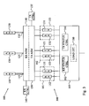
Fig. 3 is a schematic illustration of the data communication portion of aradio base station 100 and a datacommunication scheduling system 300 according to an embodiment. In this illustrative example, the radio base station serves M = 3 cells and consequently has threeantenna arrangements REs antenna arrangements respective antenna interfaces multiplexers - In the illustrative example, each
RE - In a typical implementation, at least one of the
receivers transmitters receiver status controller 162 turns off the power of one of thereceivers 132 and thetransmitter status controller 161 likewise turns off the power of one of thetransmitters 131, preferably arranged in thesame RE 103 as the turned offreceiver 132. In a second embodiment, tworeceivers transmitters - The operation of the receiver and
transmitter status controllers - Statistical information based on measurements during different portions of a day, week and/or a month can be collected by the network operator and used as a basis for determining intervals of a day, week and/or month, during which the traffic load is expected to be low enough to allow turning off receiver-transmitter pair/pairs. In particular, during night time the expected number of user equipment present in the areas of the three cells and requiring communication resources from the radio base station could on average be low enough that the receiver and
transmitter status controllers - Alternatively, an
optional load estimator 180 can be arranged in the datacommunication scheduling system 300, preferably in theREC 105. Thisload estimator 180 estimates the amount of currently buffered data to and from the user equipment in the cells to thereby get an estimate of the traffic status in the cells. If the total amount of data traffic is estimated to be below a traffic threshold, theload estimator 180 signals the receiver andtransmitter status controllers transmitters receivers load estimator 180 may optionally have access to multiple different traffic thresholds. In such a case, the receiver andtransmitter status controller first transmitter 131 andreceiver 132 if the estimated traffic load is below a first traffic threshold but exceeds a second traffic threshold. First when the estimated traffic load is below the second traffic threshold will the receiver andtransmitter status controllers second transmitter 121 andreceiver - In the embodiment illustrated in
Fig. 3 , the receiver andtransmitter status controllers REC 105 of the datacommunication scheduling system 300. - In the following discussion in connection to
Fig. 3 , it is non-limitedly assumed that the receiver andtransmitter status controllers receivers transmitters - As was mentioned in the foregoing, the receiver
antenna system multiplexer 140 connects the threereceivers antenna interfaces radio base station 100, therefore with the threeantenna arrangements antenna arrangements correct receiver antenna system multiplexer 140. The receiverantenna system multiplexer 140 in particular selectively connects the singleactive receiver 112 to thedifferent antenna interfaces receiver controller 145. - Correspondingly, the transmitter
antenna system multiplexer 150 selectively connects the threetransmitters antenna interfaces radio base station 100, therefore with the threeantenna arrangements transmitters antenna system multiplexer 150 through the antenna interfaces 115, 125, 135 to thecorrect antenna arrangement antenna system multiplexer 150 in particular selectively connects the singleactive transmitter 111 to thedifferent antenna interfaces transmitter controller 155. - The
transmitter controller 155 consequently controls the transmitterantenna system multiplexer 150 to selectively connect thetransmitter 111 to the antenna interfaces 115, 125, 135 so that therespective antenna interface transmitter 111 during at least one sub frame of a radio frame. This means that the transmitterantenna system multiplexer 150 will switch between forwarding data from thetransmitter 111 to thefirst antenna interface 115, thesecond antenna interface 125 and thethird.antenna interface 135. Furthermore, during the radio frame thetransmitter 111 is dedicated for processing and forwarding data to each of the threeantenna interfaces - Correspondingly, the
receiver controller 145 controls the receiverantenna system multiplexer 140 to selectively connect thereceiver 112 to the threeantenna interfaces respective antenna interfaces receiver 112 during at least one sub frame of the radio frame. Furthermore, the sub frame during which thereceiver 112 is connected to theantenna interface 115 of a given cell is present at the predefined sub frame distance from the sub frame during which thetransmitter 114 is connected to thesame antenna interface 115. -
Fig. 14 schematically illustrates a radio frame for the uplink (UL) and the downlink (DL) and the assignment of sub frames to the three different cells denoted A, B and C in the figure. In the figure, the uplink is indicated as one stream. LTE normally uses receiver diversity in the uplink. However, the figure merely indicates a single stream in order to simplify the understanding of the embodiments. The operations of the receiver and antenna system multiplexers 140, 150 will cause thetransmitter 111 and thereceiver 112 to be time multiplexed between the three cells. -
Fig. 15 is an example of radio frame structure with time multiplexed uplink and down link transmission for oneactive RE 101 and three served cells. In this embodiment, thetransmitter 111 sends to each of the cells A, B, C in arespective sub frame radio frame 40 and these correspond to sub frames 0 and 5 in each cell. This is preferred distribution of sub frames as today in LTE, PBCH, PSS and SSS appear in sub frames 0 and 5 in eachradio frame 40 for a cell. As a consequence, the same distribution of control signals within aradio frame 40 as the LTE standard can thereby be achieved. - Note that the sub frame indicated with
reference number 50 in the figure corresponds to sub frame 0 for the first cell A. Correspondingly, the sub frame indicated by 51 is interpreted as sub frame 0 for the second cell B and so on. - The remaining four
sub frames 58 in theradio frame 40 can be used arbitrary in the cells and preferably depending on the traffic demand in each cell. However, in order to allow ACK/NACK of downlink traffic, adownlink sub frame uplink sub frame - As is illustrated in the figure, the downlink sub frames 50, 51, 52 assigned to the different cells have corresponding uplink sub frames 53, 54, 55 present four sub frames later. One of these uplink sub frames 53, 54, 55 can be used for random access (RACH, Random Access Channel) reception in the cell.
- In order to also decrease the dynamic power consumption of the
radio base station 100, as few of the four remaining sub frames 58 are used possible. Thus, in a minimum load scenario, only six of the ten sub frames in aradio frame 40 are used for communicating data. As the traffic load increases in one or more of the cells, these extra sub frames 58 can be used to serve that traffic. - In order to improve the channel estimation for user equipment, extra sub frames can be assigned for the cell in the sub frame before the
sub frame - In an embodiment, the
REC 105 will primarily schedule the traffic in each cell on thesame sub frame transmitter 111, thetransmitter status controller 161 switches on one of the turned offtransmitters 121. - The receiver and antenna system multiplexers 140, 150 should be able to operate on micro second level, thus between sub frames, in order correctly forward data between the
active receiver 162 ortransmitter 161 and thecorrect antenna arrangement -
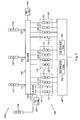
Fig. 4 is an illustration of the communicating portion of aradio base station 100 and a datacommunication scheduling system 300 according to another embodiment. In contrast to the embodiment ofFig. 3 , this datacommunication scheduling system 300 does not comprise any transmitter antenna system multiplexer. Thus, no selective forwarding of data between a single active transmitter and the threeantenna interfaces - The data
communication scheduling system 300 instead comprises a so-calledmulti-cell RE 104 that is primarily used during low load scenarios. Themulti-cell RE 104 has NTX transmitters 171, onetransmitter 171 in the figure. The multi-sector RE can have the same requirements on linearity as thenormal REs normal REs - The
multi-cell RE 104 preferably has its dedicatedantenna interface 175 connectable to adedicated antenna arrangement 170 in order to remove the need for a transmitter antenna system multiplexer. In a preferred implementation, thisantenna arrangement 170 is a so-calledomnidirectional antenna arrangement 170 capable of radiating power in all the cells served by theradio base station 100. If the combined radio coverage area of the served cells does not cover the full 360° area around theradio base station 100, theantenna arrangement 170 must not necessarily by an omnidirectional antenna but should, however, be able to transmit in the areas of the multiple cells. - The
transmitter controller 155 of the datacommunication scheduling system 300 has been illustrated implemented in theREC 105 in the figure. This should merely be seen as an illustrative example. Thetransmitter controller 155 could alternatively be arranged in themulti-cell RE 104 or be connected to theREC 105 or themulti-cell RE 104. - In this embodiment, the NTX =1
transmitter 171 is controlled by thetransmitter controller 155 for broadcasting data destined for user equipment in the M = 3 cells using the (omnidirectional)antenna arrangement 170 at the sub frames of the radio frame assigned for transmission of data to the cells. Thus, during each downlink sub frame when thetransmitter 171 sends data via theantenna interface 175 and theantenna arrangement 170, the same data is broadcast in all the cells. However, the content of the data will typically only be relevant for user equipment present in one of the cells. Thus, thetransmitter controller 155 controls thetransmitter 171 to broadcast data relevant for a first cell in all cells during a first sub frame in the radio frame. Correspondingly, thetransmitter 171 is controlled to broadcast data relevant for a second cell in all the cells during a second sub frame in the radio frame, and so on. This basically makes all the cells become one and a same cell. Compared to the solution presented inFig. 3 , the antenna gain for dedicated transmission is a factor 3 worse, assuming M = 3 . The power consumption for dedicated traffic (Joule/bit) is consequently three times higher. - In this embodiment, the
REC 105 or some other unit of the datacommunication scheduling system 300 can therefore judge when to go from this configuration with a single activemulti-cell RE 104 to threeactive REs transmitters 3 RE: 3×Power(RE static)+traffic×Power(traffic)×Efficiency(RE) 1 multi-cell RE: 1×Power(RE static)+traffic×Power(traffic)×Efficiency(RE)×3 - The formula can of course be amended based on the number of
active transmitters 171 in themulti-cell RE 104 and the number oftransmitters normal RE - The operation of the receiver
antenna system multiplexer 140 and thereceiver controller 145 is basically the same in this embodiment as compared to the embodiment illustrated inFig. 3 . -
Fig. 4 also illustrates an alternative implementation of thereceiver status controller transmitter status controller REC 105 as inFig. 3 , eachRE transmitter status controller receivers transmitters - In operation of the
radio base station 100, all thetransmitters transmitter 171 of themulti-cell RE 104 is active if the data communication scheduling is applied to all three cells. Alternatively, one of thetransmitters 111 can be active if the traffic load in the cell to which thetransmitter 111 is dedicated is particularly high as compared to the other two cells in this embodiment. In such a case, thetransmitter 171 of themulti-cell RE 104 can be shared between the other two cells and thereby switches between broadcasting data relevant for these two cells. - Correspondingly, one or two of the
receivers receiver status controllers receivers 112 handle all the uplink traffic for the cells as described above in connection withFig. 3 . This means that the antenna gain for the uplink will be same as for normal operation as theactive receiver 112 only listens to oneantenna arrangement -
Fig. 12 schematically illustrates a radio frame for the uplink and the downlink and the assignment of sub frames to the three different cells denoted A, B and C in the figure. In this embodiment, the downlink transmission is broadcast to all cells, while the receiver is time multiplexed between the cells. - The data frame structure for this configuration is shown in more detail in
Fig. 13 . In a preferred implementation, oneuplink sub frame 57 in theradio frame 40 is used for RACH. ThisRACH sub frame 57 should then be able to receive data from all cells, as random access can be transmitted by user equipment in any of the served cells. The receiverantenna system multiplexer 140 consequently connects theactive receiver 112 to all the antenna interfaces 115, 125, 135 andantenna arrangments sub frame 57. The RACH is very tolerant to the link budget but other uplink traffic scheduled to thatsub frame 57 should take the decreased antenna gain into calculation in the link adaptation. - Except for the
RACH sub frame 57, all the nine other sub frames are available for free usage in any of the cells. However, as noted above, the scheduling of uplink and downlink sub frames should be configured so that the ACK/NACK of a downlink transmission in a cell is received preferably four sub frames later in the uplink. Therefore, any scheduled transmission in the downlink should be accompanied with a corresponding possibility to receive in the uplink four sub frames later for that cell. -
Fig. 13 illustrates an example where the traffic load is equal in the different cells. In sub frame 0 50, the radio base station transmits to users in cell A, though in the form of a broadcast transmission that also reaches the other cells B, C. In sub frame 4 53, the receiverantenna system multiplexer 140 is controlled by thereceiver controller 145 to forward data received by theantenna 110 of cell A to theactive receiver 112 to thereby be able to receive the ACK/NACK from any user equipment in cell A. Correspondingly, broadcast transmissions of data destined to any user equipment in cell B and C are carried bysub frames - The
downlink sub frame 56 present the pre-defined sub frame distance prior theRACH sub frame 57 can be used for transmission of data destined in any of the cells or indeed in any combination of two or more cells. - Although not illustrated in the figure, the downlink sub frame scheduling could be conducted so that the transmission at sub frames X and X + 5 are destined to one and the same cell, thereby corresponding to the sub frames carrying the PBCH, PSS and SSS for the cell. Optionally, two consecutive sub frames can be assigned for transmission of data destined to a same cell for at least some of the cells served by the
radio base station 100. - However, in a preferred implementation of the omnitransmission, a new cell is formed covering the coverage area of the M , such as three, cells. This means that dedicated system information, i.e. information carried by the PBCH, PSS and SSS, can be transmitted during the low power consumption mode. This dedicated system information could be new system information or the system information traditionally used in one of the M cells. In order to have a smooth transient, system information of both this new cell and the M cells could be transmitted on the multi-cell RE with a slow fading out of the signal carrying the system information of the M cells on that RE. A handover between cells can then be handled more safely.
- Compared to the solution with transmitter antenna system multiplexer, the channel estimation is generally better. However, time multiplexing in the downlink as in
Fig. 3 significantly improves the antenna gain and decreases the interference caused in neighboring cells. The dynamic power consumption will also be 1/3 as compared to the omnidirectional downlink transmission. However, implementation of transmitter antenna system multiplexers leads to additional costs as they must be able to affect the switch on a high power signal, i.e. after power amplification. This should be compared to a receiver antenna system multiplexer that performs the switch on low power. The cost of the equipment in the transmitter antenna system multiplexer is generally more expensive as compared to the receiver antenna system multiplexer. - In order to improve the channel estimation possibility of the user equipment with embodiment illustrated in
Fig. 3 , two of the threetransmitters transmitter status controller 161 thereby only turns off the power of one of thetransmitters 121. It is then possible to schedule two sets of consecutive sub frames for each of the cells as is illustrated inFig. 16 . These four downlink sub frames 50, 51, 52 that are assigned to the cells therefore correspond to sub frames 0, 4, 5 and 9 in each cell. The firstactive transmitter 111 is then connected between theantenna interface 115 dedicated for the first cell A and theantenna interface 125 of the second cell B. The otheractive transmitter 131 is connected to theantenna interface 135 of the third cell C. There are several empty sub frames 58 in the figure. These sub frames can be used for selectively interconnecting either thefirst transmitter 111 or thesecond transmitter 131 to any of the antenna interfaces 115, 125, 135 to allow transmission of data for the different cells. - As is seen in the figure, it is not possible with this embodiment to have a scheduled
uplink sub frame radio frame 40. The scheduling of the uplink sub frames 53, 54, 55 by thereceiver controller 145 is therefore preferably conducted so that each cell is assigned anuplink sub frame - An advantage of this embodiment is that two antenna multiple-input and multiple-output (MIMO) transmissions can be used for 20-40 % of the sub frames, depending on the particular cell. This will allow maximum usage of time instant of good radio conditions to user equipment.
- A natural extension to the embodiment illustrated in
Fig. 16 is to also have two active receivers for the radio base station, which is illustrated inFig. 17 . Each set of two consecutive scheduled downlink sub frames 50, 51, 52 can then be followed respective uplink sub frames 53, 54, 55 scheduled four sub frames later than the downlink sub frames 50, 51, 52 for the same cell. - In
Figs. 12 to 17 , the downlink and uplink transmission are typically conducted using different carrier frequencies. This also applies toFigs. 16 and17 having two parallel downlink radio frames (Figs. 16 and17 ) and two parallel uplink radio frames (Fig. 17 ). Thus, different downlink and uplink frequencies can be used for the parallel downlink and uplink transmissions, which is well known in the art. - The embodiments of
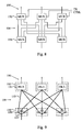
Figs. 16 and17 are in particular suitable for aradio base station 100 and datacommunication scheduling system 300 as illustrated inFig. 5 having multiple, two in the figure,transmitters receivers RE RE 101 need to be active to provide time multiplexing with twotransmitters receivers antenna system multiplexer 140 and transmitterantenna system multiplexer 150. In an alternative embodiment, eachRE transmitter receiver Fig. 5 ,REs -
Fig. 5 also illustrates an alternative implementation using anomnidirection antenna arrangement 170. In contrast toFig. 4 , no dedicated multi-cell RE is needed but one ormore transmitters normal REs antenna arrangement 170 through the transmitterantenna system multiplexer 150 and theantenna interface 175. - In a typical implementation embodiment, the
receiver status controller 162 and thetransmitter status controller 161 turn off the power of thereceivers transmitters available REs active receivers antenna system multiplexer 140 and thereceiver controller 145. In the lower power mode, the transmitterantenna system multiplexer 150 andtransmitter controller 155 are arranged for selectively connecting the twoactive transmitters omnidirectional antenna interface 175, while during normal operation they are connected to one of the normal antenna interfaces 115. - The features of the embodiments illustrated in
Figs. 3 to 5 may combine. For instance, usage ofmultiple receivers transmitters RE Fig. 5 can be used in any of the datacommunication scheduling system 300 illustrated inFigs. 3 and4 . Correspondingly, multiple REs per cell can be applied to any of the embodiments. The at least onereceiver status controller transmitter status controller REC 105 as inFigs. 3 and5 or in theREs Fig. 4 . Furthermore, theload estimator 180 illustrated inFig. 3 can also be implemented in the datacommunication scheduling system 300 ofFigs. 4 and5 . - In
Figs. 4 and5 , a separate dedicated omnidirectional antenna arrangement has been used for broadcasting data to the cells served by the radio base station. In an alternative approach, the M antenna arrangements of the radio base stations can be used to thereby simultaneously transmit the same data in all M cells. The data communication scheduling system then comprises a transmitter antenna system multiplexer interconnecting the M antenna arrangements through their respective antenna interfaces with the NTX transmitters that are active and used for the data transmission during the low power consumption operation. - The signal diagrams discussed above and illustrated in
Figs. 12 to 17 have mainly been focused on the Frequency Division Duplex (FDD) mode of LTE. However, embodiments are also fully applicable to a Time Division Duplex (TDD) system, such as the TDD mode of LTE. - The upper portion of
Fig. 23 illustrates one mode TDD defined for LTE TDD. Aradio frame 40 consists of 3 UL sub frames 53, 6 DL sub frames 50 and 1 special sub frame (SSF) 59A. As is known in the art, the first portion of theSSF 59A is used for downlink transmissions and the last portion of thesub frame 59A is employed for uplink transmissions. In this TDD mode, theSSF 59A is the second sub frame in the TDDLTE radio frame 40. - Today synchronization information intended to user equipment is transmitted in SF0 (A-DL1), part of SF1 (A-SSF), SF5 (A-DL2) and SF6 (A-DL3).
- In order to save power of the radio base station, in an embodiment two cells share radio equipment as is schematically illustrated in
Fig. 23 . The first cell is denoted A and its traditional radio frame distribution is illustrated in the upper portion of the figure, with the traditional radio frame distribution of the second cell B in the middle portion of the figure. This embodiment also takes into consideration that a downlink transmission in SF0 (A-DL1) has a corresponding ACK sent uplink in SF4 (A-UL3) and that an uplink transmission in SF4 (A-UL3) preferably has a corresponding uplink grant transmitted in SF0 (A-DL1). The second cell B uses a corresponding relationship between B-DL5 and B-U11. - The lower portion of
Fig. 23 illustrates the radio frame scheduling using one shared radio equipment, i.e. transmitter and receiver, for the two cells. One of the sub frames 58 can either be empty or be used in any of the cells. Any further cell of the radio base station would then use one or more other REs. - A challenge with TDD is that the downlink transmissions from one radio base station will cause interference in the uplink reception in another radio base station. If a neighboring radio base station uses the timing of the cell A in the upper portion of the figure above, it should omit to use the sub frame SF9 (A-DL6) as it would interfere with the reception in cell B.
- If the HARQ protocol is used according to the LTE standard, user equipment should transmit an ACK in the uplink. According to this standard, this would lead to only having one downlink sub frame per cell to transmit on as only one
uplink sub frame radio frame 40 illustrated inFig. 23 . - The HARQ protocol for LTE allows for an optimistic link adaptation as retransmissions are fast. In TDD, retransmissions are made 1 frame after the original transmissions and consequently do not affect the embodiments as its frame structure can easily be repeated every radio frame. However, in the FDD mode, the uplink retransmissions are done 8 sub frames after the initial transmission and the uplink HARQ ACK is expected four time slots or sub frames after every transmission. A missing uplink HARQ ACK leads to a retransmission.
-
Fig. 24 illustrates how the HARQ protocol can be applied to an embodiment using LTE FDD mode. In such a case, the HARQ retransmission will limit which sub frames are used in which cells, thereby reducing the flexibility slightly. -
Fig. 24 illustrates the uplink retransmissions scheduling and uplink HARQ ACK/NACK signaling for the sub frames indicated with a, A, b, B, c, C and x. Note that in the figure,sub frame A 50 is regarded as SF0 for cell A,sub frame B 51 is regarded as SF0 for cell B andsub frame C 52 is SF0 for cell C. The first uplink HARQ ACK/NACK instant for the A sub frame is indicated with A1, a second, if necessary, instant is indicated with A2 and so on. Sub frame A1/c1 denotes the sub frame where either uplink HARQ ACK/NACK for sub frame A or c can be transmitted, etc. Note that an ACK/NACK transmission in cell A cannot be sent when both transmitters are being used for transmission for other cells, B and C, as the three cells share two transmitters in this embodiment. - Also note that the transmission instants on the same HARQ process is done 8 sub frames after the preecind transmission. This means that the figure shows a compressed time line: A1 is correctly drawn but A2 actually happens one radio frame later, A3 yet another radio frame later.
- The embodiment illustrated in
Fig. 24 is adapted for the HARQ processing scheme defined in 3GPP release 8. However, the teachings of the present embodiments can of course be applied to other HARQ schemes and later revisions of the current LTE HARQ standards. - The particular numbers of the parameters M, MTX , MRX , NTX , NTX , NRX presented above should merely be seen as illustrative and non-limiting examples of the scope of the embodiments.
- The transmitter and receiver antenna system multiplexers map the transmitters and the receivers of the data communication scheduling system to different antenna interfaces. The transmitter and receiver antenna system multiplexers can be implemented in many different embodiments depending on the number of antenna interfaces, i.e. the parameter M , the number of REs and the number of transmitters and receivers per RE, i.e. the parameters MTX , MRX , and the number of configurations to support between the minimum configuration, i.e. one transmitter and one receiver for all antenna interfaces, and the maximum configuration, i.e. one RE per antenna interface. Basically, the transmitter and receiver antenna system multiplexers can be built using units selected among real time controllable radio frequency (RF) switches, RF splitters, RF amplifiers and RF filters.
-
Fig. 6 is an illustration of an embodiment of a receiverantenna system multiplexer 140. This embodiment comprises a respective low noise RF amplifier (LNA) 142 at each antenna input, arespective RF splitter 144 for generating as many copies of the amplified signal from theLNA 142 as there are connected receivers. A respective RF multiplexer (MUX) 146 is arranged at the receiver input for selecting one of the antenna signals. These RF multiplexers 146 are controlled on micro second level by the receiver controller as indicated in the figure. - In a general embodiment, the receiver
antenna system multiplexer 140 therefore comprisesM RF amplifiers 142 connected to a respective antenna interface. EachRF amplifier 142 is connected to arespective RF splitter 144 arranged for splitting the amplified RF signal from theconnected RF amplifier 142 into MRX signal copies. MRX RF multiplexers 146 have respective inputs connected to each of theM RF splitters 144 and having a respective output connected to a respective receiver of the MRX receivers in the data communication scheduling system. -
Fig. 7 illustrates an alternative receiverantenna system multiplexer 140 optimized for one shared receiver and remaining receivers, two in this example, operable on a respective dedicated antenna arrangement. In similarity toFig. 7 , each antenna interface preferably has a connected lownoise RF amplifier 142. In the figure,RF splitters 144 are connected to two of theRF amplifiers 142 and employed for splitting the input amplified RF signal into two signal copies. Asingle RF multiplexer 146 has inputs connected to theRF splitters 144 and directly to the remainingRF amplifier 142 that does not have to, but may, have aRF splitter 144. -
Fig. 8 is an illustration of a transmitterantenna system multiplexer 150 according to an embodiment. The transmitterantenna system multiplexer 150 comprises MTX RF multiplexers 156, each connecting to a respective transmitter of the data communication scheduling system. A corresponding set of M RF multiplexers 152 or RF filters are connected at the antenna interfaces. The two set ofmultiplexers combiner network 154, where the output from each transmitter andmultiplexer 156 is combined per antenna interface andmultiplexer 152. - The optional set of M RF filters (not illustrated) may be used for cleaning the RF signal from any distortion caused by the transmitter
antenna system multiplexer 150. Alternatively, the RF filters can be combined with the normal transmitter band pass filter to minimize the total loss. -
Fig. 9 is an implementation example of the transmitterantenna system multiplexer 150 illustrated inFig. 8 . The RF multiplexers 156 are implemented as a set of PIN diode switches 159. Thebold lines RF multiplexers 156 and thecombiner network 154 represent physical traces with a length corresponding to a fourth of the wavelength. By having these tuned, noRF multiplexers 152 are actually needed on the antenna arrangement sides. The figure consequently illustrates the optional RF filters 151 mentioned above to interconnect thecombiner network 154 with the antenna interfaces. -
Fig. 10 is an illustration of a transmitterantenna system multiplexer 150 that can be used in connection with broadcasting data to the multiple cells served by the radio base station. The transmitterantenna system multiplexer 150 comprises arespective RF multiplexer 156 connected to the transmitter output of the NTX active transmitters (NTX = 1 in the figure). Correspondingly, M RF multiplexers 152 are connected to the respective antenna interfaces. NTX RF splitters 158 are arranged in the transmitterantenna system multiplexer 150 so that eachRF splitter 158 is interconnected between one of the transmitter-connectingRF multiplexers 156 and theM RF multiplexers 152. Therespective RF splitter 158 divides the input RF signal into M copies that are sent on the M antenna arrangements to achieve an omni- and broadcast-like transmission of the same data to multiple served cells. -
Fig. 11 illustrates an alternative implementation for a radio base station having six antenna arrangements, three serving cells and two transmitters per cell. The transmitterantenna system multiplexer 150 may then be arranged for interconnecting one transmitter per cell with one antenna interface per cell. This means that one antenna arrangement per cell is connected through the transmitterantenna system multiplexer 150 and the other antenna arrangement per cell is directly connected to its transmitter. In low power consumption and low traffic load situations requiring, for instance, only one active transmitter per cell, the signals could then by-pass theRF multiplexers RF multiplexers - This concept of bypassing multiplexers can of course also be applied to the other embodiments of the transmitter antenna system multiplexer and receiver antenna system multiplexer disclosed herein.
- In order to illustrate the advantages of the present invention, some examples of power consumptions in a radio base station are given herein.
- In these examples, it is assumed that a RE has a static power consumption of 100 W and efficiency for dynamic traffic of 20 %. This means that transmitting X W consumes 5X W. Furthermore, 5 W per cell is used for common channels.
- Therefore, for 50W output power a total power of 550×100=350 W is consumed.
- Further, assume also that the transmitter antenna system multiplexer adds another 1.5 dB loss in the transmitter path. This will then decrease the efficiency for dynamic traffic, and to transmit X W, a total of 7X W is consumed.
- In order to have a fair comparison between the capacity, the radio base station can serve in different scenarios of RE sharing and the following assumptions can be made:
- The average capacity of a cell is less than 1/3 of the maximum capacity, due to the 1-1 reuse. It can be assumed that no major capacity loss is found if only having the radio resources ½ of the time, and a coordinated usage. The radio resources can be any of the following two: ½ the time, with full power and all frequencies or ½ the frequency, with full power and all the time.
- For simplicity, it is assumed that ¼ of the resources gives 50 % capacity, 1/8 gives 25 % capacity, etc. This is a pessimistic view on the traffic capacity as the main contribution, the interference, decreases as well. The linear approximation is probably rather good below 1/3 usage, if 3 cells per site are used. We then end up in 1-3 reuse. Below 1/3 capacity, there is no use to transmit in more than one sector at a time.
- The path loss is proportional to the radius to the power of 3.5, r3.5. This is a good first approximation and at evenly distributed traffic, the power needed to serve the traffic, in average, is then:
- 50 % power => 82 % of the radius, or 68 % of the traffic
- 40 % power => 77 % of the radius, or 60 % of the traffic
- 30 % power => 71 % of the radius, or 50 % of the traffic
- 20 % power => 63 % of the radius, or 40 % of the traffic
- 10 % power => 50 % of the radius, or 25 % of the traffic
- This is assumed that the same service is promised throughout the cell.
- In this embodiment, the radio base station is assumed to serve three cells, having three REs but each RE comprises two transmitters and two receivers. It is also assumed that two transmitters and two receivers are active and shared between the cells, while the remaining transmitters and receivers are turned off according to the invention.
-
- Static load: 6×(100 + 5×2.5) = 675 W
- Traffic load: 5X W, where X is the power in a cell
- Since all downlink signals are sent to all cells, the dynamic power consumption is 3 times the RE own dynamic load:
- Static load: 2×(100 + 3×7×2.5) = 305 W
- Traffic load: 3×7X = 21X W
- In the reference configuration, 95W is left for traffic per sector as the common channels consume 5 W.
- If we assume the same transmitters are used in the transmitter antenna system multiplexer configuration, we have (100 - 1.4×3×5)/1.4 = 56.4 W left for traffic. Note that this will be shared among the cells, resulting in a comparable output power as seen by any specific user equipment as 56/3 = 19 W.
- For any user equipment at the cell edge, this corresponds to 19/95 = 20 % of the bitrate. For an evenly distributed traffic in the cell, the capacity is slightly below 40 %.
- This means that for up to 40 % traffic load in the cell, it is sufficient with the omnidirectional downlink with transmitter antenna system multiplexer.
- For 40 % traffic load, the power per cell is 19 W and the total power consumption will be:
- Reference case: 675 + 5×19 = 770 W
- Transmitter antenna system multiplexer case: 305 + 21×19= 700W
- Thus, at 40 % traffic load, the total power consumed by the radio base station is 10 % lower with the invention and the static power consumption is less than half as compared to the reference case.
- For 25% traffic load, it is sufficient with 10 % power, or about 10 W:
- Reference case: 675 + 5×10 = 725 W
- Transmitter antenna system multiplexer case: 305 + 21×10 = 515 W
- In this embodiment, the radio base station is assumed to serve three cells, having three REs but each RE comprises two transmitters and two receivers. It is also assumed that all transmitters and receivers can be shared between the cells. However, only two transmitters and two receivers are active, while the remaining transmitters and receivers are turned off according to the invention. In the reference configuration all six transmitters and receivers are turned on.
- A transmitter antenna system multiplexer loss of 1.5 dB loss, 30 % loss, is assumed.
-
- Static load: 6x(100 + 5×2.5) = 675 W
- Traffic load: 5X W, where X is the power in a cell
-
- Static load: 2x(100 + 3×7×2.5) = 305W
- Traffic load: 7X W
- In this example, we have two transmitters and receivers serving three cells. Any of the cells can have at maximum 12 out of 20 SF, see
Fig. 17 . In average each cell has 1/3 of the transmission resources of one cell. - For any user equipment at the cell edge, only 12/20= 60 % of the bitrate is achieved, but for an average load, 1/3 of the resources are available which, according to above assumptions, corresponds to up to 65 % capacity.
- According to the assumption above, this corresponds to about 45 % of the power or 45 W.
- For 65 % traffic load, the power per cell is 45 W and the consumption will be:
- Reference case: 675 + 5×45 = 900 W
- Transmitter antenna system multiplexer case: 305 + 7×45 = 620 W
- For 25 % traffic load, it is sufficient with 10 % of the power or 10 W:
- Reference case: 675 + 5×10 = 725 W
- Transmitter antenna system multiplexer case: 305 + 7×10 = 375 W
- Thus, under the above given assumptions, onmni- and broadcast-based downlink using a transmitter antenna system multiplexer is useful for sites where the traffic load is assumed to be less than 40 % for the vast majority of the time. Time multiplexed downlink using two active transmitters/receivers shared between the three served cells is, however, useful for most sites, as an average load of 65 % can easily be handled.
-
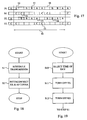
Fig. 18 is a flow diagram illustrating a method for scheduling data communication by a radio base station as disclosed herein. The method starts in step S1, where data transmission is scheduled by the radio base station for the M served cells during a radio frame using NTX transmitters of the MTX transmitters arranged in the radio base station. This data transmission scheduling of step S1 is performed so that at least one of the NTX transmitters transmits data destined to user equipment in a first of the M cells during at least one sub frame in the radio frame and transmits data destined to user equipment in a second of the M cells during at least one other sub frame in the radio frame. Furthermore, each cell of the M cells is, in the scheduling of step S1, assigned at least one sub frame of the radio frame for transmission of data destined to user equipment in the respective cell. - A next step S2 selectively connects a receiver of NRX active receivers among MRX receivers arranged in the radio base station to an antenna arrangement of M antenna arrangements arranged in the radio base station. This selective interconnecting causes at least one of the NRX receivers to be connected to a first antenna arrangement during at least one sub frame of the radio frame and connected to a second antenna arrangement during at least one other sub frame of the radio frame. Furthermore, the selective interconnection causes the antenna arrangement of each cell to be connected to one of the NRX active receivers during at least one sub frame assigned for reception of data for that cell and present at a predefined sub frame distance from the sub frame assigned to that cell for data transmission in step S1.
- The method then ends. It is though expected that the data scheduling method illustrated in
Fig. 18 can be repeated for multiple consecutive radio frames. In such a case, the same scheduling and distribution of sub frames for the cells and sharing of transmitters and receivers can be used for all these radio frames. Alternatively, the scheduling can be updated between different radio frames, for instance to take into account increasing traffic demands in one of the cells and/or decreasing traffic demands in one of the cells. -
Fig. 19 is a flow diagram illustrating additional, optional steps of the data communication scheduling method inFig. 18 . The method starts in step S10, where a time interval of day is selected during which at least some of the transmitters and receivers of the radio base station are to be turned off in order to save power. This time interval is preferably selected to be an interval, where the expected traffic load is enough to be effectively handled with the remaining transmitter/transmitters and receiver/receivers that are shared between the served cells. Statistical evaluations of measured and/or estimated traffic loads during different times of day are preferably used as a basis for selecting the time period in step S10. The next two steps S11, S12 turn off the power of MTX - NTX transmitters and MRX - NRX receivers to thereby reduce the static power consumption by the radio base station. The method then continues to step S1 ofFig. 18 , where data communication is scheduled using the remaining active MTX transmitters and MRX receivers. -
Fig. 20 is a flow diagram illustrating additional, optional steps of the data communication scheduling method ofFig. 18 . The method starts in step S20, where the traffic load in the cells served by the radio base station is estimated. This estimation can, for instance, be based on information available to the MAC scheduler, which is generally aware of the traffic status in the cells, the amount of currently buffered data to and from the served user equipment. The estimated traffic load is then compared in step S21 with one or more traffic thresholds for the purpose of determining whether the expected traffic load in the cells is sufficient low to allow turning off at least some of the transmitters and receivers of the radio base station. - In a particular embodiment, the radio base station can either operate with the full number of transmitters and receivers on or with a fixed number of transmitters and receivers turned off. In such a case, only a single traffic threshold is needed. Examples of such traffic thresholds have been given herein for the particular example situations described in the foregoing. The disclosure in connection with these examples can be used in order to calculate suitable traffic thresholds for other radio base station configurations besides the particular ones given in the examples.
- If, however, the radio base station dynamically can turn off transmitters and receivers depending on the varying traffic demands, multiple traffic thresholds can be used in step S21. The total number of transmitters and receivers that can be safely turned off for a current traffic situation is then determined based on the comparisons of the estimated traffic loads and the multiple different traffic thresholds in step S21. The selected number of transmitters and receivers are then powered down and turned off in steps S22 and S23. The method then continues to step S1 of
Fig. 18 , where the data communication of the radio base station is scheduled for the remaining active transmitter/transmitters and receiver/receivers. -
Fig. 21 is a flow diagram illustrating an additional step of the data communication scheduling method. The method continues from step S2 inFig. 18 . A next step S30 broadcasts data destined for user equipment in the served M cells using either an omnidirectional antenna arrangement connected to the active transmitter/transmitters or the M antenna arrangements dedicated for the served cells. In either case, the same data will be sent to all the cells in the relevant sub frames. By switching the data input so that the transmitted data is relevant for different cells during different sub frames, the downlink transmissions for all the cells can be served within a radio frame. -
Fig. 22 is a flow diagram illustrating an additional step of the data communication scheduling method. The method starts in step S40, where a transmitter of the NTX active transmitters is selectively connected to an antenna arrangement of the M antenna arrangements according to a scheme so that each served cell has its dedicated antenna arrangement connected to one of the active transmitters during at least one sub frame of the radio frame. This switching of the outputs of active transmitters to the different antenna arrangements achieves sufficient downlink transmissions for the served cells and user equipment. The method then continues to step S1 ofFig. 18 , where the data transmission is scheduled for the radio base station. - Thus, by sharing the same transmitters and receivers between multiple cells of a radio base station and utilizing the time division structure of the LTE air interface, a significant reduction in the static and also total power consumption can be achieved. In spite of this power consumption reduction, the resulting capacity in the shared configuration is still high.
- This means that the traditional implementation of a LTE radio base station with two transmitters and receivers per cell does not give any substantial gain in capacity due to the interference. In clear contrast, for most traffic load situations, high capacity can be with only a subset of the transmitters and receivers active and turned on, thereby reducing the power consumption of the radio base station.
- The embodiments described above are to be understood as a few illustrative examples of the present invention. It will be understood that different part solutions in the different embodiments can be combined in other configurations, where technically possible. The scope of the present invention is, however, defined by the appended claims.
Claims (24)
- A data communication scheduling system (300) adapted for arrangement in a radio base station (100) serving at least M ≥ 2 cells (10, 20, 30), said data communication scheduling system (300) is characterized by comprising:at least M antenna interfaces (115, 125, 135, 175) each connectable to an antenna arrangement of at least M antenna arrangements (110, 120, 130, 170);MTX transmitters (111, 113, 121, 123, 131, 133, 171), MTX ≥ M ;MRX receivers (112, 114, 122, 124, 132, 134), MRX ≥ M, at least one transmitter of said MTX transmitters (111, 113, 121, 123, 131, 133) and at least one receiver of said MRX receivers (112, 114, 122, 124, 132, 134) are assigned to each cell of said M cells (10, 20, 30), each transmitter of said MTX transmitters (111, 113, 121, 123, 131, 133, 171) and each receiver of said MRX receivers (112, 114, 122, 124, 132, 134) is connectable to at least one antenna interface of said at least M antenna interfaces (115, 125, 135, 175);a transmitter controller (155) arranged for scheduling data transmission by said radio base station (100) for said M cells (10, 20, 30) during a radio frame (40) comprising multiple sub frames (50-58) using NTX transmitters (111, 113, 171) of said MTX transmitters (111, 113, 121, 123, 131, 133, 171), 1 ≤ NTX < MTX , MTX - NTX remaining transmitters (121, 123, 131, 133) of said MTX transmitters (111, 113, 121, 123, 131, 133, 171) being turned off or inoperable during said radio frame (40), said transmitter controller (155) is arranged for scheduling at least one transmitter (111, 113, 171) of said NTX transmitters (111, 113, 171) for transmission of data destined for user equipment (210) in a first cell (10) of said M cells (10, 20, 30) during at least one sub frame (50) of said radio frame (40) and transmission of data destined for user equipment (220) in a second cell (20) of said M cells (10, 20, 30) during at least another sub frame (51) of said radio frame (40) and said transmitter controller (155) is arranged for assigning each cell of said M cells (10, 20, 30) at least one sub frame of said radio frame (40) for transmission of data destined for user equipment (210, 220, 230) in said each cell;a receiver antenna system multiplexer (140) connected to at least NRX receivers (112, 114) among said MRX receivers (112, 114, 122, 124, 132, 134), 1 ≤ NRX < MRX , MRX - NRX remaining receivers (122, 124, 132, 134) of said MRX receivers (112, 114, 122, 124, 132, 134) being turned off or inoperable during said radio frame (40), and the M antenna interfaces (115, 125, 135) assigned for said M cells (10, 20, 30) and arranged for selectively connecting a receiver of said NRX receivers (112, 114) to an antenna interface (115) of said M antenna interfaces (115, 125, 135); anda receiver controller (145) arranged for controlling said receiver antenna system multiplexer (140) to selectively interconnect said NRX receivers (112, 114) and said M antenna interfaces (115, 125, 135) to connect at least one receiver (112, 114) of said NRX receivers (112, 114) to a first antenna interface (115) of said at least M antenna interfaces (115, 125, 135) during at least one sub frame (53) of said radio frame (40) and to a second antenna interface (125) of said at least M antenna interfaces (115, 125, 135) during at least another sub frame (54) of said radio frame (40) and to connect, for each cell of said M cells (10, 20, 30), said antenna interface assigned to said each cell to a receiver of said NRX receivers (112, 114) during at least one sub frame i) assigned for reception of data from user equipment (210, 220, 230) in said each cell and ii) present at a predefined sub frame distance from said at least one sub frame assigned to said each cell by said transmitter controller (155).
- The data communication scheduling system according to claim 1, wherein said transmitter controller (155) is arranged for scheduling said data transmission by said radio base station (100) for said M cells (10, 20, 30) during said radio frame (40) using said NTX transmitters (111, 113, 171) to assign each cell of said M cells (10, 20, 30) at least a first sub frame and a second sub frame present in said radio frame (40) at five sub frames following said first sub frame for transmission of said data destined for said user equipment (210, 220, 230) in said each cell.
- The data communication scheduling system according to claim 1 or 2, wherein said transmitter controller (155) is arranged for scheduling said data transmission by said radio base station (100) for said M cells (10, 20, 30) during said radio frame (40) using two transmitters (111, 113) to assign ach cell of said M > 2 cells (10, 20, 30) at least two consecutive sub frames of said radio frame (40) for transmission of said data destined for said user equipment (210, 220, 230) in said each cell.
- The data communication scheduling system according to claim 3, wherein said receiver controller (145) is arranged for controlling said receiver antenna system multiplexer (140) to selectively interconnect said NRX receivers (112,114) and said M antenna interfaces (115, 125, 135) to connect, for each cell of said M cells (10, 20, 30), said antenna interface assigned to said each cell to a receiver of two receivers (112, 114) during at least two consecutive sub frames i) assigned for reception of said data from said user equipment (210, 220, 230) in said each cell and ii) present at said predefined sub frame distance from said at least two sub frames assigned to said each cell by said transmitter controller (155).
- The data communication scheduling system according to any of the claims 1 to 4, wherein said receiver controller (145) is arranged for controlling said receiver antenna system multiplexer (140) to selectively interconnect said NRX receivers (112, 114) and said M antenna interfaces (115, 125, 135) to connect, for each cell of said M cells (10, 20, 30), said antenna interface assigned to said each cell to a receiver of said NRX receivers (112, 114) during at least one sub frame i) assigned for reception of said data from said user equipment (210, 220, 230) in said each cell and ii) present in said radio frame four sub frames following said at least one sub frame assigned to said each cell by said transmitter controller (155).
- The data communication scheduling system according to any of the claims 1 to 5, further comprising:a transmitter status controller (161, 163, 165, 167) arranged for turning off said MTX - NTX remaining transmitters (121, 123,131,133) of said MTX transmitters (111, 113, 121, 123, 131, 133, 171); anda receiver status controller (162, 164, 166, 168) arranged for turning off said MRX - NRX remaining receivers (122, 124, 132, 134) of said MRX receivers (112, 114, 122, 124, 132, 134).
- The data communication scheduling system according to claim 6, wherein said transmitter status controller (161, 163, 165, 167) and said receiver status controller (162, 164, 166, 168) are arranged for turning off said MTX - NTX remaining transmitters (121, 123, 131, 133) and said MRX - NRX remaining receivers (122, 124, 132, 134) at a predefined time interval of a day.
- The data communication scheduling system according to claim 6 or 7, further comprising a load estimator (180) arranged for generating a control signal if an estimated, expected data traffic load in said M cells (10, 20, 30) during a time interval is below a traffic threshold, wherein said transmitter status controller (161, 163, 165. 167) and said receiver status controller (162, 164, 166,168) are response to said control signal and turn off said MTX - NTX remaining transmitters (121, 123, 131, 133) and said MRX - NRX remaining receivers (122, 124,132,134) based on said control signal.
- The data communication scheduling system according to any of the claims 1 to 8, wherein said NTX transmitters (171) are arranged for broadcasting data destined for said user equipment (210, 220, 230) in said M cells (10, 20, 30) using a omnidirectional antenna arrangement (170) connectable to an antenna interface (175) of said at least M antenna interfaces (115, 125,135,175) at said sub frames of said multiple sub frames (50-55) assigned for transmission of said data by said transmitter controller (155).
- The data communication scheduling system according to any of the claims 1 to 9, further comprising a transmitter antenna system multiplexer (150) connected to at least said NTX transmitters (111,113) and said M antenna interfaces (115, 125,135) and arranged for selectively connecting a transmitter of said NTX transmitters (111.113) to an antenna interface of said M antenna interfaces (115, 125, 135), wherein said transmitter controller (155) is arranged for controlling said transmitter antenna system multiplexer (150) to selectively interconnect said NTX transmitters (111,113) and said M antenna interfaces (115,125,135) to connect, for each cell of said M cells (10, 20, 30), said antenna interface assigned to said each cell to a transmitter of said NTX transmitters (111, 113) during said at least one sub frame assigned for transmission of said data destined for said user equipment (210, 220, 230) in said each cell.
- The data communication scheduling system according to claim 10, wherein said transmitter antenna system multiplexer (150) comprises.MTX radio frequency multiplexers (156) each connected to a respective transmitter of said MTX transmitters (111, 113, 121, 123, 131,133);M radio frequency filters (151) each connected to a respective antenna interface of said M antenna interfaces (115,125,135); anda combiner network (154) interconnecting each radio frequency filter of said M radio frequency filters (151) with each radio frequency multiplexer of said MTX radio frequency multiplexers (156).
- The data communication Scheduling system according to claim 10, wherein said transmitter antenna system multiplexer(150) comprises:M first radio frequency multiplexers (152) connected to a respective antenna interface of said M antenna interfaces (115, 125, 135):NTX second radio frequency multiplexers (156) connected to a respective transmitter of said NTX transmitters (111,113) and a respective first radio frequency multiplexer of said M first radio frequency multiplexers (152); andNTX radio frequency splitters (158) connected to a respective second radio frequency multiplexer of said NTX second radio frequency multiplexers (156) and said M first radio frequency multiplexers (152).
- The data communication scheduling system according to any of the claims 1 to 12, wherein said receiver antenna system multiplexer (140) comprises:M radio frequency amplifiers (142) connected to a respective antenna interface of said M antenna interfaces (115,125,135);M radio frequency splitters (144) connected to a respective radio frequency amplifier of said M radio frequency amplifiers (142) and arranged for splitting an amplified radio frequency signal into MRX signal copies; andMRX radio frequency multiplexers (146) connected to a respective receiver of said MRX receivers (112, 114, 122, 124,132,136) and said M radio frequency splitters (144).
- A radio base station (100) comprising:at least M antenna arrangements (110, 120,130,170); anda data communication scheduling system (300) according to any of the claims 1 to 13, wherein each of said at least M antenna arrangements (110, 120, 130, 170) is connected to a respective antenna interface (115, 125, 135, 175) of said data communication scheduling system (300).
- A method for scheduling data communication by a radio base station (100) serving at least M ≥ 2 cells (10, 20, 30) and comprising at least M antenna arrangements (110, 120, 130, 170), MTX transmitters (111, 113, 121, 123, 131, 133, 171), MTX ≥M , and MRX receivers (112, 114, 122, 124, 132,134), MRX ≥ M each cell of said M cells (10, 20, 30) being assigned at least one transmitter of said MTX transmitters (111, 113, 121, 123, 131, 133), at least one receiver of said MRX receivers (112, 114, 122, 124, 132, 134) and an antenna arrangement of said at least M antenna arrangements (110, 120, 130), each transmitter of said MTX transmitters (111, 113, 121, 123, 131, 133, 171) is connectable to at least one antenna arrangement of said at least M antenna arrangements (110, 120, 130, 170) and each receiver of said MRX receivers (112, 114, 122, 124, 132, 134) is connectable to at least one antenna arrangement of said at least M antenna arrangements (110,120, 130), said method is characterized by the steps:scheduling data transmission by said radio base station (100) for said M cells (10, 20, 30) during a radio frame (40) comprising multiple sub frames (50-58) using NTX transmitters (111, 131, 171) of said MTX transmitters (111, 113, 121, 123, 131, 133, 171), 1 ≤ NTX < MTX , MTX - NTX remaining transmitters (121, 123, 131, 133) of said MTX transmitters (111, 113, 121, 123, 131, 133, 171) being turned off or inoperable during said radio frame (40) by scheduling at least one transmitter (11, 113, 171) of said NTX transmitters (111, 131, 171) to transmits data destined for user equipment (210) in a first cell (10) of said M cells (10, 20, 30) during at least one sub frame (50) of said radio frame (40) and to transmits data destined for user equipment (220) in a second cell (20) of said M cells (10, 20, 30) during at least another sub frame (51) of said radio frame (40) and by assigning each cell of said M cells (10, 20, 30) at least one sub frame of said radio frame (40) for transmission of data destined for user equipment (210, 220, 230) in said each cell; andselectively connecting a receiver of NRX receivers (112, 114) among said MRX receivers (112, 114, 122, 124, 132, 134), 1 ≤ NRX < MRX , MRX - NRX remaining receivers (122, 124, 132, 134) of said MRX receivers (112, 114, 122, 124, 132, 134) being turned off or inoperable during said radio frame (40), to an antenna arrangement of said M antenna arrangements (110, 120, 130) by connecting at least one receiver (112, 114.) of said NRX receivers (112, 114) to a first antenna arrangement (110) of said M antenna arrangements (110, 120, 130) during at least one sub frame (53) of said radio frame (40) and to a second antenna arrangement (120) of said M antenna arrangements (110, 120, 130) during at least another sub frame (54) of said radio frame (40) and by connecting, for each cell of said M cells (10, 20, 30), said antenna arrangement assigned to said each cell to a receiver of said NRX receivers (112, 114) during at least one sub frame i) assigned for reception of data from user equipment (210, 220, 230) in said each cell and ii) present at a predefined sub frame distance from said at least one sub frame assigned to said each cell for transmission of data.
- The method according to claim 15, wherein said step of scheduling data transmission comprises scheduling said data transmission by said radio base station (100) for said M cells (10, 20, 30) during said radio frame (40) using said NTX transmitters (111, 131, 171) by assigning each cell of said M cells (10, 20, 30) at least a first sub frame and a second sub frame present in said radio frame (40) at five sub frames following said first sub frame for transmission of said data destined for said user equipment (210, 220, 230) in said each cell.
- The method according to claim 15 or 16, wherein said step of scheduling data transmission comprises scheduling said data transmission by said radio base station (100) for said M cells (10, 20, 30) during said radio frame (40) using two transmitters (111, 113) by assigning each cell of said M > 2 cells (10, 20, 30) at least two consecutive sub frames of said radio frame (40) for transmission of said data destined for said user equipment (210, 220, 230) in said each cell.
- The method according to claim 17, wherein said step of selectively connecting a receiver comprises selectively connecting said receiver of said NRX receivers (112,114) to said antenna arrangement of said M antenna arrangements (110, 120, 130) by connecting, for each cell of said M cells (10, 20, 30), said antenna arrangement assigned to said each cell to a receiver of two receivers (112, 114) during at least two consecutive sub frames i) assigned for reception of said data from said user equipment (210, 220, 230) in said each cell and ii) present at said predefined sub frame distance from said at least two sub frames assigned to said each cell for transmission of data.
- The method according to any of the claims 15 to 18, wherein said step of selectively connecting a receiver comprises selectively connecting said receiver of said NRX receivers (112,114) to said antenna arrangement of said M antenna arrangements (110, 120, 130) by connecting, for each cell of said M cells (10, 20, 30), said antenna arrangement assigned to said each cell to a receiver of said NRX receivers (112,114) during at least one sub frame i) assigned for reception of said data from said user equipment in said each cell and ii) present in said radio frame four sub frames following said at least one sub frame assigned to said each cell for transmission of data.
- The method according to any of the claims 15 to 19, further comprising the steps of:turning off said MTX - NTX remaining transmitters (121, 123,131,133) of said MTX transmitters (111,113,121. 123,131,133,171); andturning off said MRX - NRX remaining receivers (122, 124.132, 134) of said MRX receivers (112,114,122, 124, 132,134).
- The method according to claim 20, wherein said steps of turning off said MTX - NTX remaining transmitters (121. 123, 131, 133) and said MRX - NRX remaining receivers (122, 124, 132, 134) are performed at a predefined time interval of a day.
- The method according to claim 20 or 21, further comprising the step of estimating an expected data traffic load in said M cells (10,20, 30) during a time interval, wherein said steps of turning off said MTX - NTX remaining transmitters (121, 123, 131, 133) and said MRX - NRX remaining receivers (122, 124, 133, 134) are triggered if said expected data traffic load is below a traffic threshold.
- The method according to any of the claims 15 to 22 further comprising the step of said NTX transmitters (171) broadcasting data destined for said user equipment (210, 220, 230) in said M cells (10, 20, 30) using a omnidirectional antenna arrangement (170) connected to said NTX transmitters (171) at said sub frames of said radio frame (40) assigned for transmission of said data.
- The method according to any of the claims 15 to 23, wherein said step of scheduling data transmission comprises selectively connecting a transmitter of said NTX transmitters (111, 113) to an antenna arrangement of said M antenna arrangements (110, 120, 130) by connecting, for each cell of said M cells (10, 20, 30), said antenna arrangement assigned to said each cell to a transmitter of said NTX transmitters (111,113) during said at least one sub frame assigned for transmission of said data destined for said user equipment (210, 220, 230) in said each cell.
Applications Claiming Priority (1)
| Application Number | Priority Date | Filing Date | Title |
|---|---|---|---|
| PCT/SE2009/050370 WO2010117313A1 (en) | 2009-04-08 | 2009-04-08 | Data communication scheduling |
Publications (2)
| Publication Number | Publication Date |
|---|---|
| EP2417802A1 EP2417802A1 (en) | 2012-02-15 |
| EP2417802B1 true EP2417802B1 (en) | 2013-03-20 |
Family
ID=41560086
Family Applications (1)
| Application Number | Title | Priority Date | Filing Date |
|---|---|---|---|
| EP09788521A Active EP2417802B1 (en) | 2009-04-08 | 2009-04-08 | Data communication scheduling |
Country Status (4)
| Country | Link |
|---|---|
| US (1) | US8626088B2 (en) |
| EP (1) | EP2417802B1 (en) |
| CN (1) | CN102461280B (en) |
| WO (1) | WO2010117313A1 (en) |
Families Citing this family (33)
| Publication number | Priority date | Publication date | Assignee | Title |
|---|---|---|---|---|
| US8201205B2 (en) | 2005-03-16 | 2012-06-12 | Tvworks, Llc | Upstream bandwidth management methods and apparatus |
| WO2011081042A1 (en) * | 2010-01-04 | 2011-07-07 | 日本電気株式会社 | Power-saving operation support device, power-saving operation support method, recording medium, and base station |
| US20120315948A1 (en) * | 2010-02-24 | 2012-12-13 | Telefonaktiebolaget Lm Ericsson (Publ) | Method and Apparatus for Controlling Energy Consumption in a Multi-Antenna Base Station |
| KR20110114175A (en) * | 2010-04-13 | 2011-10-19 | 삼성전자주식회사 | Apparatus and method for saving power consumption in broadband wireless communication system |
| CN102378323B (en) | 2010-08-13 | 2014-12-10 | 电信科学技术研究院 | Energy-saving compensation method and base station |
| GB2484347A (en) * | 2010-10-08 | 2012-04-11 | Nec Corp | Initiating energy saving mode based on the activity of mobile communications equipment over an LTE-A interface |
| US9252874B2 (en) | 2010-10-13 | 2016-02-02 | Ccs Technology, Inc | Power management for remote antenna units in distributed antenna systems |
| US9160449B2 (en) | 2010-10-13 | 2015-10-13 | Ccs Technology, Inc. | Local power management for remote antenna units in distributed antenna systems |
| CN103181099A (en) * | 2010-11-03 | 2013-06-26 | 瑞典爱立信有限公司 | Repeater device |
| EP2643947B1 (en) | 2010-11-24 | 2018-09-19 | Corning Optical Communications LLC | Power distribution module(s) capable of hot connection and/or disconnection for distributed antenna systems, and related power units, components, and methods |
| US11296504B2 (en) | 2010-11-24 | 2022-04-05 | Corning Optical Communications LLC | Power distribution module(s) capable of hot connection and/or disconnection for wireless communication systems, and related power units, components, and methods |
| US20140051433A1 (en) * | 2011-03-07 | 2014-02-20 | Otmar Rengert | Method and an apparatus for reducing energy consumption in a base station of a corrdless telephone |
| US8750187B2 (en) * | 2011-05-13 | 2014-06-10 | Qualcomm Incorporated | Data driven adaptive receive chain diversity processing |
| US20120300710A1 (en) * | 2011-05-27 | 2012-11-29 | Nokia Siemens Networks Oy | Distributing L2 Baseband Processing in a Radio Network |
| EP2721880B1 (en) * | 2011-06-16 | 2019-01-16 | Telefonaktiebolaget LM Ericsson (publ) | Method and arrangement in a network node |
| CN103621175A (en) * | 2011-06-22 | 2014-03-05 | 瑞典爱立信有限公司 | Adaptive filtering architecture |
| US11323337B2 (en) | 2011-09-27 | 2022-05-03 | Comcast Cable Communications, Llc | Resource measurement and management |
| US8797852B2 (en) * | 2012-06-11 | 2014-08-05 | Alcatel Lucent | Dynamical bandwidth adjustment of a link in a data network |
| US9154222B2 (en) | 2012-07-31 | 2015-10-06 | Corning Optical Communications LLC | Cooling system control in distributed antenna systems |
| CN102833831A (en) * | 2012-08-21 | 2012-12-19 | 中兴通讯股份有限公司 | Network card device, routing device, system and method for realizing dynamic dormancy and wakeup |
| US9166690B2 (en) * | 2012-09-25 | 2015-10-20 | Corning Optical Communications LLC | Power distribution module(s) for distributed antenna systems, and related power units, components, systems, and methods |
| US10257056B2 (en) | 2012-11-28 | 2019-04-09 | Corning Optical Communications LLC | Power management for distributed communication systems, and related components, systems, and methods |
| US9923702B2 (en) * | 2013-01-25 | 2018-03-20 | Mediatek Singapore Pte. Ltd. | Sectorization feedback and multi-sector transmission in wireless networks |
| US9106557B2 (en) | 2013-03-13 | 2015-08-11 | Comcast Cable Communications, Llc | Scheduled transmission of data |
| US9801164B2 (en) | 2013-04-18 | 2017-10-24 | Lg Electronics Inc. | Methods and devices for transmitting scheduling request in wireless access system |
| EP3039814B1 (en) | 2013-08-28 | 2018-02-21 | Corning Optical Communications Wireless Ltd. | Power management for distributed communication systems, and related components, systems, and methods |
| WO2015079435A1 (en) | 2013-11-26 | 2015-06-04 | Corning Optical Communications Wireless Ltd. | Selective activation of communications services on power-up of a remote unit(s) in a distributed antenna system (das) based on power consumption |
| US9785175B2 (en) | 2015-03-27 | 2017-10-10 | Corning Optical Communications Wireless, Ltd. | Combining power from electrically isolated power paths for powering remote units in a distributed antenna system(s) (DASs) |
| CN108282165B (en) * | 2017-12-25 | 2021-08-17 | 中国电子科技集团公司电子科学研究院 | Wireless communication system architecture |
| CN108702700B (en) * | 2018-03-16 | 2020-06-02 | 北京小米移动软件有限公司 | Indication and search method and device for defining cell synchronous broadcast block position and base station |
| WO2019174046A1 (en) | 2018-03-16 | 2019-09-19 | 北京小米移动软件有限公司 | Method and apparatus for indicating and searching for position of synchronous broadcast block of defined cell, and base station |
| EP4213525A4 (en) * | 2020-11-02 | 2024-03-27 | Samsung Electronics Co Ltd | Method for controlling plurality of cells for providing wireless resources to plurality of terminals, and electronic device performing same |
| WO2023274523A1 (en) * | 2021-06-30 | 2023-01-05 | Telefonaktiebolaget Lm Ericsson (Publ) | A communication node for adaptively controlling power consumption |
Family Cites Families (17)
| Publication number | Priority date | Publication date | Assignee | Title |
|---|---|---|---|---|
| EP0947108A2 (en) | 1996-12-09 | 1999-10-06 | Siemens Aktiengesellschaft | Base station for a radio telecommunications system |
| FI108764B (en) | 1997-05-28 | 2002-03-15 | Nokia Corp | Control of transceiver units in a cellular radio system |
| JP3119605B2 (en) | 1997-10-28 | 2000-12-25 | 埼玉日本電気株式会社 | Wireless base station |
| KR20000002504A (en) * | 1998-06-20 | 2000-01-15 | 윤종용 | Selective transmitting diversity device of mobile communication system and method thereof |
| US6584330B1 (en) * | 2000-07-18 | 2003-06-24 | Telefonaktiebolaget Lm Ericsson (Publ) | Adaptive power management for a node of a cellular telecommunications network |
| ATE390025T1 (en) | 2003-12-19 | 2008-04-15 | Ericsson Telefon Ab L M | ADAPTIVE POWER CONTROL FOR A NODE OF A TELECOMMUNICATIONS NETWORK |
| KR101026156B1 (en) * | 2005-09-27 | 2011-04-05 | 노키아 코포레이션 | Pilot structure for multicarrier transmissions |
| CN101185200B (en) * | 2005-11-14 | 2011-07-20 | 桥扬科技有限公司 | Multiple-antenna system for cellular communication and broadcasting |
| KR101049616B1 (en) * | 2006-10-31 | 2011-07-14 | 콸콤 인코포레이티드 | Unified design and centralized scheduling for dynamic simo, su-mimo and mu-mimo operation for rl transmissions |
| AU2008204768A1 (en) * | 2007-01-11 | 2008-07-17 | Qualcomm Incorporated | Using DTX and DRX in a wireless communication system |
| US8498639B2 (en) * | 2007-02-09 | 2013-07-30 | Qualcomm Incorporated | Flexible channel quality indicator reporting |
| US7797013B2 (en) | 2007-02-28 | 2010-09-14 | Telefonaktiebolaget Lm Ericsson (Publ) | Radio communications using scheduled power amplifier backoff |
| US8908581B2 (en) * | 2007-05-01 | 2014-12-09 | Qualcomm Incorporated | Extended microsleep for communications |
| US20080287163A1 (en) * | 2007-05-17 | 2008-11-20 | Telefonaktiebolaget Lm Ericsson (Publ), | Method and apparatus for converting between a multi-sector, omni-base station configuration and a multi-sector base station configuration |
| EP2120493A1 (en) | 2008-03-19 | 2009-11-18 | Nokia Siemens Networks Oy | Mechanism for automated re-configuration of an access network element |
| US8340199B2 (en) * | 2008-10-27 | 2012-12-25 | Samsung Electronics Co., Ltd. | 8-transmit antenna reference signal design for downlink communications in a wireless system |
| US9026124B2 (en) * | 2009-03-31 | 2015-05-05 | Futurewei Technologies, Inc. | System and method for interference mitigation in a wireless communications system |
-
2009
- 2009-04-08 EP EP09788521A patent/EP2417802B1/en active Active
- 2009-04-08 US US13/263,207 patent/US8626088B2/en active Active
- 2009-04-08 WO PCT/SE2009/050370 patent/WO2010117313A1/en active Application Filing
- 2009-04-08 CN CN200980159854.1A patent/CN102461280B/en active Active
Also Published As
| Publication number | Publication date |
|---|---|
| EP2417802A1 (en) | 2012-02-15 |
| US20120063377A1 (en) | 2012-03-15 |
| CN102461280B (en) | 2015-02-04 |
| WO2010117313A1 (en) | 2010-10-14 |
| CN102461280A (en) | 2012-05-16 |
| US8626088B2 (en) | 2014-01-07 |
Similar Documents
| Publication | Publication Date | Title |
|---|---|---|
| EP2417802B1 (en) | Data communication scheduling | |
| EP2737758B1 (en) | Method for resource management in a cellular communication network and resource management system | |
| US8565827B2 (en) | Method and apparatus for power saving in wireless communication node B | |
| KR101546641B1 (en) | Method and apparatus for cooperative wireless communications | |
| US8515495B2 (en) | MIMO communication system | |
| TWI517733B (en) | Uplink power control for distributed wireless communications | |
| JP5666572B2 (en) | Scheduling data transmission between a mobile terminal and a base station in a wireless communication network | |
| EP2190234B1 (en) | Base station and method for covering a plurality of areas by one cell | |
| US8538352B2 (en) | Radio base transceiver station and power supplying method | |
| EP2472961B1 (en) | Base station power saving method and system | |
| JP2007534241A (en) | Distributed radio system that centrally controls resources | |
| CN103518412A (en) | Method, radio network controller, radio base station and user equipment for selecting downlink mode | |
| US8964607B2 (en) | Communication system, communication apparatus, and communication method | |
| CN104412535A (en) | Methods and nodes for multiple user mimo scheduling | |
| JP6232991B2 (en) | Wireless access system and wireless control device | |
| US20100086070A1 (en) | User apparatus, base station apparatus, mobile communication system and communication control method | |
| US11690008B2 (en) | Saving power in remote radio heads | |
| JP2011166806A (en) | Mobile communication system, base station control device, and mobile terminal | |
| EP2856800B1 (en) | Methods and devices in communication system | |
| US9191901B2 (en) | Radio base station and power control method | |
| US20220110064A1 (en) | Systems and methods for high power uplink transmission |
Legal Events
| Date | Code | Title | Description |
|---|---|---|---|
| PUAI | Public reference made under article 153(3) epc to a published international application that has entered the european phase |
Free format text: ORIGINAL CODE: 0009012 |
|
| 17P | Request for examination filed |
Effective date: 20111014 |
|
| AK | Designated contracting states |
Kind code of ref document: A1 Designated state(s): AT BE BG CH CY CZ DE DK EE ES FI FR GB GR HR HU IE IS IT LI LT LU LV MC MK MT NL NO PL PT RO SE SI SK TR |
|
| DAX | Request for extension of the european patent (deleted) | ||
| REG | Reference to a national code |
Ref country code: DE Ref legal event code: R079 Ref document number: 602009014270 Country of ref document: DE Free format text: PREVIOUS MAIN CLASS: H04W0052020000 Ipc: H04W0072120000 |
|
| GRAP | Despatch of communication of intention to grant a patent |
Free format text: ORIGINAL CODE: EPIDOSNIGR1 |
|
| RIC1 | Information provided on ipc code assigned before grant |
Ipc: H04W 52/02 20090101ALN20120919BHEP Ipc: H04W 72/12 20090101AFI20120919BHEP Ipc: H04W 88/08 20090101ALN20120919BHEP |
|
| RIC1 | Information provided on ipc code assigned before grant |
Ipc: H04W 52/02 20090101ALN20120924BHEP Ipc: H04W 72/12 20090101AFI20120924BHEP Ipc: H04W 88/08 20090101ALN20120924BHEP |
|
| GRAS | Grant fee paid |
Free format text: ORIGINAL CODE: EPIDOSNIGR3 |
|
| GRAA | (expected) grant |
Free format text: ORIGINAL CODE: 0009210 |
|
| AK | Designated contracting states |
Kind code of ref document: B1 Designated state(s): AT BE BG CH CY CZ DE DK EE ES FI FR GB GR HR HU IE IS IT LI LT LU LV MC MK MT NL NO PL PT RO SE SI SK TR |
|
| REG | Reference to a national code |
Ref country code: GB Ref legal event code: FG4D |
|
| REG | Reference to a national code |
Ref country code: CH Ref legal event code: EP |
|
| REG | Reference to a national code |
Ref country code: IE Ref legal event code: FG4D |
|
| REG | Reference to a national code |
Ref country code: AT Ref legal event code: REF Ref document number: 602720 Country of ref document: AT Kind code of ref document: T Effective date: 20130415 |
|
| REG | Reference to a national code |
Ref country code: DE Ref legal event code: R096 Ref document number: 602009014270 Country of ref document: DE Effective date: 20130516 |
|
| PG25 | Lapsed in a contracting state [announced via postgrant information from national office to epo] |
Ref country code: BG Free format text: LAPSE BECAUSE OF FAILURE TO SUBMIT A TRANSLATION OF THE DESCRIPTION OR TO PAY THE FEE WITHIN THE PRESCRIBED TIME-LIMIT Effective date: 20130620 Ref country code: SE Free format text: LAPSE BECAUSE OF FAILURE TO SUBMIT A TRANSLATION OF THE DESCRIPTION OR TO PAY THE FEE WITHIN THE PRESCRIBED TIME-LIMIT Effective date: 20130320 Ref country code: ES Free format text: LAPSE BECAUSE OF FAILURE TO SUBMIT A TRANSLATION OF THE DESCRIPTION OR TO PAY THE FEE WITHIN THE PRESCRIBED TIME-LIMIT Effective date: 20130701 Ref country code: NO Free format text: LAPSE BECAUSE OF FAILURE TO SUBMIT A TRANSLATION OF THE DESCRIPTION OR TO PAY THE FEE WITHIN THE PRESCRIBED TIME-LIMIT Effective date: 20130620 Ref country code: LT Free format text: LAPSE BECAUSE OF FAILURE TO SUBMIT A TRANSLATION OF THE DESCRIPTION OR TO PAY THE FEE WITHIN THE PRESCRIBED TIME-LIMIT Effective date: 20130320 |
|
| REG | Reference to a national code |
Ref country code: NL Ref legal event code: T3 |
|
| REG | Reference to a national code |
Ref country code: AT Ref legal event code: MK05 Ref document number: 602720 Country of ref document: AT Kind code of ref document: T Effective date: 20130320 |
|
| REG | Reference to a national code |
Ref country code: LT Ref legal event code: MG4D |
|
| PG25 | Lapsed in a contracting state [announced via postgrant information from national office to epo] |
Ref country code: LV Free format text: LAPSE BECAUSE OF FAILURE TO SUBMIT A TRANSLATION OF THE DESCRIPTION OR TO PAY THE FEE WITHIN THE PRESCRIBED TIME-LIMIT Effective date: 20130320 Ref country code: FI Free format text: LAPSE BECAUSE OF FAILURE TO SUBMIT A TRANSLATION OF THE DESCRIPTION OR TO PAY THE FEE WITHIN THE PRESCRIBED TIME-LIMIT Effective date: 20130320 Ref country code: SI Free format text: LAPSE BECAUSE OF FAILURE TO SUBMIT A TRANSLATION OF THE DESCRIPTION OR TO PAY THE FEE WITHIN THE PRESCRIBED TIME-LIMIT Effective date: 20130320 Ref country code: GR Free format text: LAPSE BECAUSE OF FAILURE TO SUBMIT A TRANSLATION OF THE DESCRIPTION OR TO PAY THE FEE WITHIN THE PRESCRIBED TIME-LIMIT Effective date: 20130621 |
|
| PG25 | Lapsed in a contracting state [announced via postgrant information from national office to epo] |
Ref country code: HR Free format text: LAPSE BECAUSE OF FAILURE TO SUBMIT A TRANSLATION OF THE DESCRIPTION OR TO PAY THE FEE WITHIN THE PRESCRIBED TIME-LIMIT Effective date: 20130320 Ref country code: BE Free format text: LAPSE BECAUSE OF FAILURE TO SUBMIT A TRANSLATION OF THE DESCRIPTION OR TO PAY THE FEE WITHIN THE PRESCRIBED TIME-LIMIT Effective date: 20130320 |
|
| PG25 | Lapsed in a contracting state [announced via postgrant information from national office to epo] |
Ref country code: EE Free format text: LAPSE BECAUSE OF FAILURE TO SUBMIT A TRANSLATION OF THE DESCRIPTION OR TO PAY THE FEE WITHIN THE PRESCRIBED TIME-LIMIT Effective date: 20130320 Ref country code: IS Free format text: LAPSE BECAUSE OF FAILURE TO SUBMIT A TRANSLATION OF THE DESCRIPTION OR TO PAY THE FEE WITHIN THE PRESCRIBED TIME-LIMIT Effective date: 20130720 Ref country code: AT Free format text: LAPSE BECAUSE OF FAILURE TO SUBMIT A TRANSLATION OF THE DESCRIPTION OR TO PAY THE FEE WITHIN THE PRESCRIBED TIME-LIMIT Effective date: 20130320 Ref country code: CZ Free format text: LAPSE BECAUSE OF FAILURE TO SUBMIT A TRANSLATION OF THE DESCRIPTION OR TO PAY THE FEE WITHIN THE PRESCRIBED TIME-LIMIT Effective date: 20130320 Ref country code: RO Free format text: LAPSE BECAUSE OF FAILURE TO SUBMIT A TRANSLATION OF THE DESCRIPTION OR TO PAY THE FEE WITHIN THE PRESCRIBED TIME-LIMIT Effective date: 20130320 Ref country code: PT Free format text: LAPSE BECAUSE OF FAILURE TO SUBMIT A TRANSLATION OF THE DESCRIPTION OR TO PAY THE FEE WITHIN THE PRESCRIBED TIME-LIMIT Effective date: 20130722 Ref country code: SK Free format text: LAPSE BECAUSE OF FAILURE TO SUBMIT A TRANSLATION OF THE DESCRIPTION OR TO PAY THE FEE WITHIN THE PRESCRIBED TIME-LIMIT Effective date: 20130320 |
|
| PG25 | Lapsed in a contracting state [announced via postgrant information from national office to epo] |
Ref country code: CY Free format text: LAPSE BECAUSE OF FAILURE TO SUBMIT A TRANSLATION OF THE DESCRIPTION OR TO PAY THE FEE WITHIN THE PRESCRIBED TIME-LIMIT Effective date: 20130320 Ref country code: PL Free format text: LAPSE BECAUSE OF FAILURE TO SUBMIT A TRANSLATION OF THE DESCRIPTION OR TO PAY THE FEE WITHIN THE PRESCRIBED TIME-LIMIT Effective date: 20130320 |
|
| REG | Reference to a national code |
Ref country code: CH Ref legal event code: PL |
|
| PG25 | Lapsed in a contracting state [announced via postgrant information from national office to epo] |
Ref country code: MC Free format text: LAPSE BECAUSE OF FAILURE TO SUBMIT A TRANSLATION OF THE DESCRIPTION OR TO PAY THE FEE WITHIN THE PRESCRIBED TIME-LIMIT Effective date: 20130320 |
|
| PLBE | No opposition filed within time limit |
Free format text: ORIGINAL CODE: 0009261 |
|
| STAA | Information on the status of an ep patent application or granted ep patent |
Free format text: STATUS: NO OPPOSITION FILED WITHIN TIME LIMIT |
|
| REG | Reference to a national code |
Ref country code: IE Ref legal event code: MM4A |
|
| PG25 | Lapsed in a contracting state [announced via postgrant information from national office to epo] |
Ref country code: LI Free format text: LAPSE BECAUSE OF NON-PAYMENT OF DUE FEES Effective date: 20130430 Ref country code: CH Free format text: LAPSE BECAUSE OF NON-PAYMENT OF DUE FEES Effective date: 20130430 Ref country code: DK Free format text: LAPSE BECAUSE OF FAILURE TO SUBMIT A TRANSLATION OF THE DESCRIPTION OR TO PAY THE FEE WITHIN THE PRESCRIBED TIME-LIMIT Effective date: 20130320 |
|
| REG | Reference to a national code |
Ref country code: FR Ref legal event code: ST Effective date: 20131231 |
|
| 26N | No opposition filed |
Effective date: 20140102 |
|
| PG25 | Lapsed in a contracting state [announced via postgrant information from national office to epo] |
Ref country code: FR Free format text: LAPSE BECAUSE OF NON-PAYMENT OF DUE FEES Effective date: 20130521 Ref country code: IT Free format text: LAPSE BECAUSE OF FAILURE TO SUBMIT A TRANSLATION OF THE DESCRIPTION OR TO PAY THE FEE WITHIN THE PRESCRIBED TIME-LIMIT Effective date: 20130320 |
|
| REG | Reference to a national code |
Ref country code: DE Ref legal event code: R097 Ref document number: 602009014270 Country of ref document: DE Effective date: 20140102 |
|
| PG25 | Lapsed in a contracting state [announced via postgrant information from national office to epo] |
Ref country code: IE Free format text: LAPSE BECAUSE OF NON-PAYMENT OF DUE FEES Effective date: 20130408 |
|
| PG25 | Lapsed in a contracting state [announced via postgrant information from national office to epo] |
Ref country code: MT Free format text: LAPSE BECAUSE OF FAILURE TO SUBMIT A TRANSLATION OF THE DESCRIPTION OR TO PAY THE FEE WITHIN THE PRESCRIBED TIME-LIMIT Effective date: 20130320 |
|
| PG25 | Lapsed in a contracting state [announced via postgrant information from national office to epo] |
Ref country code: TR Free format text: LAPSE BECAUSE OF FAILURE TO SUBMIT A TRANSLATION OF THE DESCRIPTION OR TO PAY THE FEE WITHIN THE PRESCRIBED TIME-LIMIT Effective date: 20130320 |
|
| PG25 | Lapsed in a contracting state [announced via postgrant information from national office to epo] |
Ref country code: LU Free format text: LAPSE BECAUSE OF NON-PAYMENT OF DUE FEES Effective date: 20130408 Ref country code: MK Free format text: LAPSE BECAUSE OF FAILURE TO SUBMIT A TRANSLATION OF THE DESCRIPTION OR TO PAY THE FEE WITHIN THE PRESCRIBED TIME-LIMIT Effective date: 20130320 Ref country code: HU Free format text: LAPSE BECAUSE OF FAILURE TO SUBMIT A TRANSLATION OF THE DESCRIPTION OR TO PAY THE FEE WITHIN THE PRESCRIBED TIME-LIMIT; INVALID AB INITIO Effective date: 20090408 |
|
| PGFP | Annual fee paid to national office [announced via postgrant information from national office to epo] |
Ref country code: DE Payment date: 20220427 Year of fee payment: 14 |
|
| PGFP | Annual fee paid to national office [announced via postgrant information from national office to epo] |
Ref country code: NL Payment date: 20230426 Year of fee payment: 15 |
|
| PGFP | Annual fee paid to national office [announced via postgrant information from national office to epo] |
Ref country code: GB Payment date: 20230427 Year of fee payment: 15 |
|
| REG | Reference to a national code |
Ref country code: DE Ref legal event code: R119 Ref document number: 602009014270 Country of ref document: DE |
|
| PG25 | Lapsed in a contracting state [announced via postgrant information from national office to epo] |
Ref country code: DE Free format text: LAPSE BECAUSE OF NON-PAYMENT OF DUE FEES Effective date: 20231103 |