CN103621175A - Adaptive filtering architecture - Google Patents
Adaptive filtering architecture Download PDFInfo
- Publication number
- CN103621175A CN103621175A CN201180071808.3A CN201180071808A CN103621175A CN 103621175 A CN103621175 A CN 103621175A CN 201180071808 A CN201180071808 A CN 201180071808A CN 103621175 A CN103621175 A CN 103621175A
- Authority
- CN
- China
- Prior art keywords
- chain
- sector signal
- switch
- antenna
- radio
- Prior art date
- Legal status (The legal status is an assumption and is not a legal conclusion. Google has not performed a legal analysis and makes no representation as to the accuracy of the status listed.)
- Pending
Links
Images


Classifications
-
- H—ELECTRICITY
- H04—ELECTRIC COMMUNICATION TECHNIQUE
- H04W—WIRELESS COMMUNICATION NETWORKS
- H04W52/00—Power management, e.g. TPC [Transmission Power Control], power saving or power classes
- H04W52/02—Power saving arrangements
- H04W52/0203—Power saving arrangements in the radio access network or backbone network of wireless communication networks
- H04W52/0206—Power saving arrangements in the radio access network or backbone network of wireless communication networks in access points, e.g. base stations
-
- H—ELECTRICITY
- H04—ELECTRIC COMMUNICATION TECHNIQUE
- H04W—WIRELESS COMMUNICATION NETWORKS
- H04W16/00—Network planning, e.g. coverage or traffic planning tools; Network deployment, e.g. resource partitioning or cells structures
- H04W16/02—Resource partitioning among network components, e.g. reuse partitioning
- H04W16/06—Hybrid resource partitioning, e.g. channel borrowing
- H04W16/08—Load shedding arrangements
-
- H—ELECTRICITY
- H04—ELECTRIC COMMUNICATION TECHNIQUE
- H04W—WIRELESS COMMUNICATION NETWORKS
- H04W88/00—Devices specially adapted for wireless communication networks, e.g. terminals, base stations or access point devices
- H04W88/08—Access point devices
-
- Y—GENERAL TAGGING OF NEW TECHNOLOGICAL DEVELOPMENTS; GENERAL TAGGING OF CROSS-SECTIONAL TECHNOLOGIES SPANNING OVER SEVERAL SECTIONS OF THE IPC; TECHNICAL SUBJECTS COVERED BY FORMER USPC CROSS-REFERENCE ART COLLECTIONS [XRACs] AND DIGESTS
- Y02—TECHNOLOGIES OR APPLICATIONS FOR MITIGATION OR ADAPTATION AGAINST CLIMATE CHANGE
- Y02D—CLIMATE CHANGE MITIGATION TECHNOLOGIES IN INFORMATION AND COMMUNICATION TECHNOLOGIES [ICT], I.E. INFORMATION AND COMMUNICATION TECHNOLOGIES AIMING AT THE REDUCTION OF THEIR OWN ENERGY USE
- Y02D30/00—Reducing energy consumption in communication networks
- Y02D30/70—Reducing energy consumption in communication networks in wireless communication networks
Landscapes
- Engineering & Computer Science (AREA)
- Computer Networks & Wireless Communication (AREA)
- Signal Processing (AREA)
- Mobile Radio Communication Systems (AREA)
- Amplifiers (AREA)
Abstract
The invention provides a node used in a wireless communication system comprising at least two Tx-chains and at least two Rx-chains. A first means for a switch and filter network function MSN is arranged across all the Tx-chains. The first MSN is arranged to output one antenna sector signal comprising: a radio sector signal, or a split radio sector signal. The splitting of a radio sector signal allows one radio sector signal to feed sector antennas in more than one sector, each sector having at least one sector antenna. The first MSN or a second MSN can also be arranged across the Rx-chains. The invention also provides a method to reduce power consumption in a node and a wireless communication system comprising the node.
Description
Technical field
The present invention relates to such as the node in the communication systems such as dissimilar radio base station (RBS) of using in wireless communication system with for reducing the field of the parts of power consumption in node.
Background technology
The demand of WiMAX is being increased, and be constantly suggested for the different solutions that satisfy the demands.A solution is the spectrum efficiency that improves communication network, and this can be by the new radio access technologies LTE(Long Term Evolution of introducing) carry out.
The another way of carrying out this operation is dispose more base stations and use Geng little community, and the capacity of system will increase.Yet has also brought expensive high energy consumption a large amount of base stations, and environment is had to negative effect.In addition, the high bit rate of WiMAX needs many signals to process in base station in the future, and this even will further increase energy consumption.Therefore, conventionally need to be reduced in the energy consumption in base station.
The intensive deployment of many little community and base station may also cause the increase of common-channel interference between different districts.Common-channel interference will cause worsening signal interference plus noise than (SINR) with therefore for client's lower bit rate.
A prior art solution for reducing the power consumption of base station is called " three sector, omnis " (Three sector omni).This refers to that, during low business situation, three sector base stations are closed two in three base band, radio and power amplifiers substantially, and uses base band, radio and a power amplifier to serve all three sectors.Radio link in use is connected to the existing fan antenna at website, thereby obtains effective omni-directional mode.The solution of this type is described in WO 2008/143567 A1.
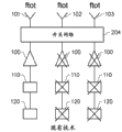
Base station often has three sectors, and each sector has its oneself base band, radio and power amplifier, referring to Fig. 1 a and 1b.The first fan antenna 101 covers the first sector, and the second fan antenna 102 covers the second sector, and the 3rd fan antenna 103 covers the 3rd sector.At transfer mode, Tx pattern, in downlink mode, each antenna be connected to comprise with the unit Series for Tx radio 110 be connected, for the parts of Tx base band 120 and the Tx chain (conveyer chain) of power amplifier 100, power amplifier is connected to fan antenna.Each sector operates in total frequency band ftot of RBS.Most of power consumption is in power amplifier, but also consumes sizable power for Tx base band and the wireless parts of Tx.Today, all three sectors are moved and all the time regardless of business load amount in base station.Due to for Tx base band and the wireless all parts of Tx and for the power amplifier of all sectors in continuous operation, this causes unnecessary high power consumption.
Radio base station is at receiving mode, Rx pattern, and when operating in uplink mode, each fan antenna is also connected to Rx chain (receive chain) as shown in Figure 1 b.The radio base station of Fig. 1 b comprises three sectors with three Tx chains and three Rx chains.Each Tx chain and each Rx chain comprise antenna end and radio end, and antenna end is connected to a Tx/Rx switch 130.Each Tx/Rx switch arrangement becomes fan antenna 101,102,103 is switched to a Tx or a Rx chain, and fan antenna is arranged in a certain sector, operate in space.Each Tx chain comprises the parts for Tx base band 120 and Tx radio 110 and power amplifier 100 PA that are connected in series, and power amplifier is connected to Tx/Rx switch 130.Each Rx chain comprises the parts for Rx base band 160 and Rx radio 150 and low noise amplifier 140 LNA that are connected in series, and low noise amplifier is connected to Tx/Rx switch 130.Each Tx chain is arranged to operate in total transmission band ftx, and each Rx chain is arranged to operate in total frequency acceptance band frx.Switching in sector between Rx and Tx pattern is carried out by being embodied as the Tx/Rx switch 130 of duplexer or circulator.
Fig. 2 illustrates the energy-conservation solution that is called " three sector, omnis ".In " three sector, omnis ", switching network 204 is between fan antenna 101-103 and power amplifier.For low business situation, can deploy switch network, so that Tx base band 120, a Tx radio 110 and a power amplifier 100 are served all three sectors.Residue Tx base band, Tx radio and power amplifier can be closed subsequently to reduce power consumption.Whole frequency band ftx will be used in each sector.This causes comparing with the prior art solution shown in Fig. 1 a, from the gain of the radiation diagram of the fan antenna of website, will reduce by 5 dB.This is by the capacity of website be coated with negative effect.
Above-mentioned prior art solution also can be used in Rx pattern.Much smaller in power dissipation ratio transfer mode in receiving mode, but certainly also wish to be reduced in the power consumption in receiving mode.
The problem relevant with prior art solution is by three sector radio base stations illustrations.Yet problem is applicable to the node in communication system conventionally, as radio base station dissimilar in wireless communication system.
Therefore, needing may be at low business load, particularly in transfer mode, realizes reducing power consumption and to total capacity with cover the improvement node without negative effect.
Summary of the invention
The object of the invention is to reduce at least some relevant shortcomings of mentioning of prior art solution, and provide:
● node, and
● reduce the method for power consumption in node
With solve realize power-dissipation-reduced node and to the total capacity of website with cover the problem without negative effect.
This object comprises that by a kind of the node using in the wireless communication system of at least two Tx chains and at least two Rx chains is achieved.Each Tx chain and each Rx chain comprise antenna end and radio end.Antenna end is directly or indirectly connected to fan antenna.Each fan antenna is arranged in certain sector, operate in space, each Tx chain comprise be connected in series for Tx base band and the wireless parts of Tx and power amplifier PA, and power amplifier is directly or indirectly connected to a fan antenna.Each Rx chain comprise be connected in series for Rx base band and the wireless parts of Rx and low noise amplifier LNA, and low noise amplifier is directly or indirectly connected to a fan antenna.Each Tx chain is arranged to operating in total transmission band ftx, and each Rx chain is arranged to operating in total receive frequency frx, wherein, for the first component MSN of switch and FL-network function, before or after power amplifier, across all Tx chains, arranges.The one MSN comprises at least one sef-adapting filter and the separator member with input and output, and its output is connected to the input of at least one switch/combiner parts.The one MSN is arranged to directly or indirectly receive at least one the radio sector signal from least one Tx chain at the input of its corresponding sef-adapting filter and separator member, and from an antenna sector signal of output output of switch/combiner parts described in each, antenna sector signal comprises:
● from the radio sector signal of its corresponding Tx chain, radio sector signal is arranged to operate in total transmission band ftx, or
● from the separated radio sector signal of any Tx chain, separated radio sector signal is arranged to operate in a part of total transmission band tx,
The separation of radio sector signal allows a radio sector signal to be fed to the fan antenna in more than one sector, and each sector has at least one fan antenna.
This object is also achieved by a kind of method that is reduced in the power consumption in node as described in claim 1-18 any one, wherein:
● before or after power amplifier, across all Tx chains, insert a MSN, and/or across all Rx chains, inserted the 2nd MSN before or after low noise amplifier, or
● after power amplifier and before low noise amplifier, across all Tx and Rx chain, insert a MSN
And wherein, traffic load information receives at the control inputs to the first and/or the 2nd MSN.By the processing unit in the first and/or the 2nd MSN, or manually, the first and/or the 2nd MSN configuration sef-adapting filter and separator member and switch/combiner parts, to minimize the quantity of radio sector signal, thus by means of from first and/or the processing unit of the 2nd MSN to the control signal of Tx and Rx chain or manually or external control signal, permission is closed complete or part Tx and/or Rx chain to all fan antennas needs and/or forwarding from each minimizing of the radio sector signal of the informational needs of all antenna sectors signal for supplying antenna sector signal with respect to business load.
The present invention also provides the wireless communication system that comprises node as described in claim 1-18.
By being achieved as follows one or several feature of the dependent claims of explaining, realized additional advantage.
Accompanying drawing explanation
Fig. 1 a illustrate schematically all sectors in transfer mode in total bandwidth ftot the prior art solution of node of operation simultaneously.
Fig. 1 b illustrate schematically all sectors transmit and receiving mode in the prior art solution of the node that simultaneously operates in total bandwidth ftot.
Fig. 2 illustrates prior art solution " three sector, omnis " schematically.
Fig. 3 illustrates a basic configuration of the present invention schematically.
Fig. 4 illustrates another basic configuration of the present invention schematically.
Fig. 5 illustrates schematically for configuring the different possibilities of MSN.
Fig. 6 illustrates the principle of carrier aggregation schematically.
Fig. 7 illustrates the generic configuration possibility for the first or the 2nd MSN schematically.
Fig. 8 illustrates the example for the configuration possibility of a MSN schematically.
Fig. 9 illustrates an example of 1 minute 2 separator schematically.
Figure 10 illustrates an example of 1 minute 3 separator schematically.
Figure 11 illustrates the first ios dhcp sample configuration IOS DHCP of a MSN schematically.
Figure 12 illustrates the second ios dhcp sample configuration IOS DHCP of a MSN schematically.
Figure 13 illustrates the 3rd ios dhcp sample configuration IOS DHCP of a MSN schematically.
Figure 14 illustrates the another example for the configuration possibility of a MSN schematically.
Figure 15 illustrates the 4th ios dhcp sample configuration IOS DHCP of a MSN schematically.
Example of the present invention when Figure 16 a is illustrated in schematically and realizes in FDD system in Tx and Rx pattern.
Example of the present invention when Figure 16 b is illustrated in schematically and realizes in TDD system in Tx and Rx pattern.
Figure 17 illustrates the block diagram of an example of method of the present invention.
Embodiment
Now with reference to accompanying drawing Fig. 3-14, the present invention is described.Fig. 1 a, 1b and 2 description that is associated with background parts.The node that the present invention expection is used for a kind of wireless communication system that comprises at least two Tx chains and at least two Rx chains.Each Tx chain and each Rx chain comprise antenna end and radio end.Antenna end is directly or indirectly connected to fan antenna 101,102,103.Each fan antenna is arranged in certain sector, operate in space, and each Tx chain comprises the parts for Tx base band 120 and Tx radio 110 and power amplifier 100 PA that are connected in series, and power amplifier is directly or indirectly connected to a fan antenna.Each Rx chain comprises the parts for Rx base band 160 and Rx radio 150 and low noise amplifier 140 LNA that are connected in series, and low noise amplifier is directly or indirectly connected to a fan antenna.Each Tx chain is arranged to operate in total transmission band ftx, and each Rx chain is arranged to operate in total frequency acceptance band frx.
To explain now direct be indirectly connected.
Basic idea of the present invention is separated available band between a plurality of sectors of node service.Conventionally, whole available band is used in each sector of node, but for low business situation, only the partial-band of whole frequency band will be enough to process the business in each sector.While cutting apart whole frequency band between sector, can close some base band, radio and power amplifier to save energy.
Therefore in specification and claim, fan antenna is defined for any applicable antenna of radio communication, as array antenna, bipolar or paster antenna.
The present invention, therefore by illustrating by being included in the example of the node of three sector RBS in transfer mode, realizes under powered pattern because this is most probable.Also may in receiving mode, use the present invention, this is also by shown in Figure 16.In transfer mode, the Tx chain of node operates in total transmission band ftx, and in receiving mode, the Rx chain of node operates in total frequency acceptance band frx.The present invention also can be used in such as the nodes such as radio base station with two, four or more sectors.Yet the present invention is applicable to conventionally such as the dissimilar nodes such as radio base station.
The present invention can realize in wireless communication system, as FDD(Frequency Division Duplexing (FDD)) and TDD(time division duplex).In FDD system, ftx and frx separate, but in TDD, ftx equals frx.
Fig. 3 illustrates a basic configuration of the present invention of the node in the transfer mode for operating three sectors in total transmission band ftx such as radio base station (RBS) etc.Herein, for the first component MSN 301 of switch and FL-network function, before power amplifier, between power amplifier 100 and Tx radio 110, across all Tx chains, arrange.The one MSN can be used in all Tx base band of closing except a Tx base band and Tx radio and Tx radio so that energy-conservation.As will be further explained, a MSN comprises at least one switch/combiner parts and at least one sef-adapting filter and separator member.The one MSN is arranged to receive at least one the radio sector signal 304 from least one Tx chain, and exports an antenna sector signal 305-307 from the output of switch/combiner parts described in each.Depending on business, antenna sector signal comprises the separated radio sector signal that uses the radio sector signal of total transmission band ftx or the sub-band of the part that use comprises total transmission band ftx.By arranging that switch/combiner parts and sef-adapting filter and the load of separator member response service are configured, each separated radio sector signal is arranged to be sent to different sectors, the quantity of the radio sector signal that therefore can need to all fan antennas with respect to business load optimization supply antenna sector signal.The one MSN can receive the information from business load in the different sectors of cordless communication network, and determine for Tx base band and the wireless parts of Tx and whether can close for Rx base band and the wireless parts of Rx based on this information, and if can close, determine will close for base band and wireless which parts.For closing also of base band and wireless parts, can directly from wireless communication system, to relating to base band and radio, start, what close is which base band and radio to the one MSN by notified subsequently, and configure subsequently a MSN, as will be further explained.
Fig. 4 illustrates the of the present invention another basic configuration of the node in the transfer mode for operating three sectors in total transmission band ftx such as radio base station (RBS) etc.Herein, a MSN 401 after power amplifier 100, arranges across all Tx chains between fan antenna 101-103 and power amplifier.The one MSN as above works in addition as described in a MSN in Fig. 3.Described in can be as above except total transmission band ftx in the present invention associated with Fig. 3, be divided into two or three sub-bands, this solution utmost point is similar to " three sector, omnis ".In the present invention, use the configuration with three sub-frequency bands, during one sub-frequency bands of each sector, compare with " three sector, omnis ", this increases about 5dB by the gain that makes radiation diagram.As by illustrative, other configuration is also possible.
Direction with reference to radio sector signal is carried out the definition before or after power amplifier, that is, before power amplifier, be before radio sector signal arrives power amplifier between Tx radio 110 and power amplifier 100.After power amplifier, be radio sector signal by after power amplifier between power amplifier 100 and fan antenna 101-103.When the present invention all realizes in FDD in Tx and two kinds of patterns of Rx, if Tx and Rx chain have public sections antenna, Tx/Rx switch is connected to fan antenna to switch between Tx and Rx pattern, and when Tx and Rx pattern all realize in TDD, Tx/Rx switch arrangement is between MSN and Tx/Rx chain, if Figure 16 is by illustrating.
In Fig. 3 and 4, unshowned Rx chain can be connected to common sector antenna with corresponding Tx chain through Tx/Rx switch, and Tx/Rx switch switches in sector between Tx and Rx pattern.Tx/Rx switch for example can be embodied as duplexer or circulator.Tx and Rx chain also can have its respective sector antennas, this means in one or several sector and to exist for the independent fan antenna of Rx with for the independent fan antenna of Tx.In the case, without Tx/Rx switch.In three sector site, for example each can have the Tx/Rx switch being connected to Tx and the common fan antenna of Rx chain for two sectors, and sector can tool for the separate antenna of Tx chain with for the separate antenna of Rx chain.This means that Tx or Rx chain directly or are indirectly connected to fan antenna through Tx/Rx switch.Indirectly connect therefore and can realize by Tx/Rx switch.
Another kind of possibility is in one or several sector, to have more than one Tx and/or more than one Rx chain.This is for example the situation in LTE system.In the case, Tx and Rx chain can be as mentioned above use public sections antenna through Tx/Rx switch, or one or several Tx chain and one or several Rx chain have its respective sector antennas, and therefore Tx/Rx switch does not need.Another possibility is Rx and/or the Tx chain existing for the varying number of each sector.If for example have 2 Tx chains and 4 Rx chains in a sector, can have two kinds of combinations of Tx/Rx chain, each combination is connected to fan antenna through Tx/Rx switch, and two other fan antennas each be connected to Rx chain.
Fig. 5-16 illustrate different example of the present invention and details.Figure 17 illustrates the example that reduces the method for the present invention of power consumption in node.
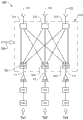
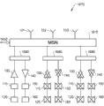
Fig. 5 illustrates the more detailed description of a MSN.In this diagram, a MSN comprises three sef-adapting filters and separator member 501-503 and three switch/combiner parts 511-513.
Fig. 5 illustrates for configuring the different possibilities of a MSN of the present invention.Referring to Figure 16 b and associated text, the 2nd MSN also can configure in the same manner.Node 500 comprises with three Rx chains and three Tx chains, the RBS of a Tx1, the 2nd Tx2 and the 3rd Tx3.Each Tx chain comprises the parts for Tx base band 120 and Tx radio 110 and power amplifier 100 PA that are connected in series, and each power amplifier is connected to sef-adapting filter and separator member.Rx chain is not shown in Figure 5.Tx chain is arranged to operate in first, second, and third sector of the correspondence first, second, and third radio sector signal s1-s3 with being arranged to generate in Tx chain, wherein, each radio sector signal s1-s3 is arranged to operate in total transmission band ftx, and is arranged through first, second, and third path p1-p3 forwarding.The one MSN 510 arranges across all Tx chains after power amplifier, as in the basic configuration of Fig. 4, and comprise first, second, and third sef-adapting filter and separator member 501-503 and first, second, and third switch/combiner parts 511-513.The one MSN 510 also can be as arranged across all Tx chains according in the basic configuration of Fig. 3 before power amplifier.
The one MSN 510 is arranged to directly or indirectly receive at least one the radio sector signal from least one Tx chain at the input of its corresponding sef-adapting filter and separator member, and from an antenna sector signal of output output of switch/combiner parts described in each, antenna sector signal comprises:
● from the radio sector signal of its corresponding Tx chain, radio sector signal is arranged to operate in total transmission band ftx, or
● from the separated radio sector signal of any Tx chain, separated radio sector signal is arranged to operate in a part of total transmission band tx,
The separation of radio sector signal allows a radio sector signal to be fed to the fan antenna in more than one sector, and each sector has at least one fan antenna.
The one MSN also has below by the control inputs 550 of further explaining.Control inputs can be supplied for MSN the information of relevant business load.
The first sef-adapting filter and separator can be arranged to the first path p1 to be separated into three subpaths, subpath to switch/combiner parts, and each subpath expection is for the separation of the first radio sector signal s1 and the subsignal of filtration.
The second sef-adapting filter and separator can be arranged to the second path p2 to be separated into three subpaths, subpath to switch/combiner parts, and each subpath expection is for the separation of the second radio sector signal s2 and the subsignal of filtration.
The 3rd sef-adapting filter and separator can be arranged to Third Road footpath p3 to be separated into three subpaths, subpath to switch/combiner parts, and each subpath expection is for the separation of the 3rd radio sector signal s3 and the subsignal of filtration.
Sef-adapting filter and separator member are therefore for a radio sector signal s1-s3 is separated into one or several subsignal, and which part of adaptive control frequency band will be in each subsignal.In the example of Fig. 5, each radio sector signal is separated into three subsignals.Each subsignal is arranged to operate in a part of total transmission band ftx.The separation of radio sector signal is with the subsignal of filtration also referred to as separated radio sector signal, and the separated and antenna sector signal that filters is also referred to as separate antenna sector signals.
Described in Fig. 5, separated possibility requires each sef-adapting filter and separating component to comprise that 1 minute 3 separator member or another parts are to carry out the separated of three subsignals.It is for example shown in Figure 8 that one of sef-adapting filter and separating component have the example of configuration of 1 minute 3 separator member.As in other example by illustrating, sef-adapting filter also can provide the directapath for not separated radio sector signal with separating component.
The same as mentioned, can response service load and configure sef-adapting filter and separator member and the switch/combiner parts of a MSN, can minimize with respect to business load the quantity of the radio sector signal that antenna sector signal provision is needed to all fan antennas thus.This can complete by the traffic load information that is arranged to receive at the control inputs 550 to a MSN.By the processing unit in a MSN, the one MSN is arranged through the configuration of processing unit and traffic load information control sef-adapting filter and separator member 501-503 and switch/combiner parts 511-513, to minimize the quantity of radio sector signal.The 2nd MSN of description associated with Figure 16 a can be take as above as the same way response service load described in a MSN is configured.
Traffic load information can be arranged to from wireless communication system or from external source, be fed to the control inputs 550 of a MSN.
For minimize the quantity of radio sector signal with respect to business load, the configuration of sef-adapting filter and separator member 501-503 and switch/combiner parts 511-513 can be arranged by the manual adjustment of sef-adapting filter/separator member and switch/combiner parts.
A part of or complete Tx and/or Rx chain can be arranged to by means of the processing unit from a MSN to the control signal of Tx or Rx chain or manually or external control signal be that each minimizing of radio sector signal is closed.
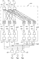
Fig. 6 illustrates for comprising the principle of carrier aggregation of the node 600 of a MSN 610.Node 600 comprises with three Rx chains and three Tx chains, the RBS of a Tx1, the 2nd Tx2 and the 3rd Tx3.Rx chain is not shown in Figure 6.The configuration of Fig. 6 is with as above for having identical function described in Fig. 5, and difference is at low frequency carrier signal part Txl(the Tx1l-Tx3l in low frequency part 620 in the example at Fig. 6) and the example of high frequency carrier part Txh(at Fig. 6 in Tx1h-Tx3h in HFS 630) in cut apart the parts for Tx radio 110 and the power amplifier 100 for each Tx chain of three Tx chains.Each carrier wave in each Tx chain is partly connected to a sef-adapting filter and separator member 601-606.Carrier aggregation can realize by node, wherein, in at least two carrier wave parts, cut apart at least one Tx chain for the wireless parts of Tx and power amplifier, each carrier wave part operates in a part of total transmission band ftx, and each carrier wave is partly arranged to the radio sector signal of cutting apart in the frequency range of carrier wave part to be forwarded to a sef-adapting filter and separator member 601-606, and sef-adapting filter and separator member are arranged to:
● by separated, cut apart radio sector signal and be forwarded to its corresponding switch/combiner parts 611-613, wherein, the radio sector signal of cutting apart is arranged to be combined into an antenna sector signal that comprises all carrier wave parts, antenna sector signal is arranged for operating in total transmission band ftx, therefore this signal comprises be arranged to the radio sector signal that operates in total transmission band, or
● forward at least two " separating radio sector signals ", each " separating radio sector signal " is arranged to be forwarded to different switch/combiner, wherein, " separating radio sector signal " from different carrier part is combined into a separate antenna sector signals that comprises all carrier wave parts, separate antenna sector signals is arranged for operating in the part at total transmission band ftx, therefore this signal comprises the separated radio sector signal from any Tx chain, separated radio sector signal is arranged to operate in a part of total transmission band ftx.
" separating radio sector signal " be as described in associated with for example Fig. 5 in separator the separated and radio sector signal of cutting apart that filters.
Needn't be in different carrier part divided ownership Tx chain.One of Tx chain for example can not cut apart, and two cut apart.Also may be divided into more than two frequency ranges.The major advantage of carrier aggregation is that the bandwidth in each Tx chain can increase, and expands thus total transmission band ftx.Carrier aggregation also can be used in Rx pattern.
Fig. 7 illustrates the generic configuration possibility for the first or the 2nd MSN 710.N in Fig. 7 represents the sum for the fan antenna of all sectors.Owing to there being at least one fan antenna in each sector, therefore, N is equal to or greater than the quantity of sector.M represent according to Fig. 5 for example for the sum of the FDD application Tx chain of the configuration of a MSN or for example according to Figure 16 a in FDD application for the total of the Rx chain of the 2nd MSN or the sum at the TDD application Tx/Rx of MSN chain according to Figure 16 b for example.
In the example of Fig. 7, therefore the first or the 2nd MSN 700 comprises M sef-adapting filter and separator member 701 and N switch/combiner parts 702, wherein, M >=N, and the quantity of exporting at the output of sef-adapting filter and separator member equals N, and equal M in the quantity of the input input of switch/combiner parts, allow thus each sef-adapting filter and separator member to be connected to each switch/combiner parts.
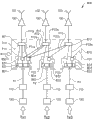
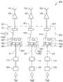
Fig. 8 illustrates the example for the configuration possibility of a MSN of the present invention.Node 800 comprises three Rx chains and three Tx chains, a Tx1, the 2nd Tx2 and the 3rd Tx3.Tx chain is arranged to operate in first, second, and third sector of the correspondence first, second, and third radio sector signal s1-s3 with being arranged to generate in Tx chain, wherein, each radio sector signal s1-s3 is arranged to operate in total transmission band ftx, and is arranged through first, second, and third path (p1-p3) forwarding.As in the basic configuration of Fig. 3, the one MSN 810 arranged across all Tx chains before power amplifier, and comprise first, second, and third sef-adapting filter and separator member 801-803, each parts has input and output, and its output is connected to first, second, and third switch/combiner parts 811-813 input one of at least.The output of each switch/combiner parts is directly or indirectly connected to fan antenna through power amplifier.Sef-adapting filter and separator member comprise respectively first, second, and third switch block 821-823 and first, second, and third 1 minutes 2 separator member 831-833.The first sef-adapting filter and separator member also comprise the one 1 minute 3 separator member 834.Each separator member comprises separation and filter function.The first switch block receives the first radio sector signal from a Tx chain, and second switch parts receive the second radio sector signal from the 2nd Tx chain, and the 3rd switch block receives the 3rd radio sector signal from the 3rd Tx chain.Each switch block is arranged to:
● through switch/combiner parts and power amplifier, the antenna sector signal that is included in the radio sector signal in the Tx chain of switch block is directly or indirectly forwarded to fan antenna, or
● through switch/combiner parts and power amplifier, will be included in 1 minute 2 separator member or directly or indirectly be forwarded to fan antenna at the antenna sector signal of the separated radio sector signal of 1 minute 3 separator member, separated radio sector signal is also at least two Tx chain repeatings
The first switch block has three position: A, B and C, and the second and the 3rd switch block has two position A and B.The one MSN 810 also arranged across all Tx chains before power amplifier according to the basic configuration of Fig. 4.
The first switch block 821 exists:
A position, the first radio sector signal is forwarded to the first switch/combiner 811,
B position, the first radio sector signal is forwarded to the one 1 minute 2 separator member 831,
C position, the first radio sector signal is forwarded to the one 1 minute 3 separator member 834.
A position, the second radio sector signal is forwarded to second switch/combiner 812,
B position, the second radio sector signal is forwarded to the 21 minute 2 separator member 832.
The 3rd switch block 823 exists:
A position, the 3rd radio sector signal is forwarded to the 3rd switch/combiner 813,
B position, the 3rd radio sector signal is forwarded to the 31 minute 2 separator member 833.
An example of the design of three 1 minute 2 separator member 831-833 can be seen, and can see at Figure 10 for the example of 1 minute 3 separator member 834 in Fig. 9.
Fig. 8 is illustrated in the example for the Tx pattern possibility configured separate of three sector RBS with Tx chain Tx1-Tx3.For the possible path of the first radio sector signal, by solid line, illustrate, for the possible path of the second radio sector signal, by dash line, illustrate, and illustrate by chain-dotted line for the possible path of the 3rd radio sector signal.
The first path, sector is:
● for comprising the first subpath p11 in the first path of the first subsignal of the first radio sector signal s1 of separated and unfiltered the first radio sector signal s1
● for be expressed as the first radio sector signal s1 second with the 3rd subsignal s11a and s12 and be from the second and the 3rd subpath in the first path of the radio sector signal s1 of the separated and filtration of the output of the one 1 minute 2 separator member 831, be expressed as p11a and p12
● for be expressed as the first radio sector signal s1 the 4th, the 5th with the 6th subsignal s11b, s12a and s13 and be from the 4th, the 5th and the 6th subpath in the first path of the separated of the output of the one 1 minute 3 separator member 834 and the radio sector signal s1 that filters, be expressed as p11b, p12a and p13.
The second path, sector is:
● for comprising the first subpath p22 in the second path of the first subsignal of the second radio sector signal s2 of separated and unfiltered the second radio sector signal s2
● for be expressed as the second radio sector signal s2 second with the 3rd subsignal s22a and s23 and be from the second and the 3rd subpath in the second path of the radio sector signal s2 of the separated and filtration of the output of the 21 minute 2 separator member 832, be expressed as p22a and p23
The 3rd path, sector is:
● for comprising the first subpath p33 in Third Road footpath of the first subsignal of the 3rd radio sector signal s3 of separated and unfiltered the 3rd radio sector signal s3
● for be expressed as the 3rd radio sector signal s3 second with the 3rd subsignal s33a and s31 and be from the second and the 3rd subpath in the Third Road footpath of the radio sector signal s3 of the separated and filtration of the output of the 31 minute 3 separator member 833, be expressed as p33a and p31
The first switch block 821 is in A position time, and the first radio sector signal s1 in the first subpath p11 enters the first switch/combiner parts 811 and ingoing power amplifier 100 subsequently.
If the first switch block 821 is in B position, the first radio sector signal s1 enters the one 1 minute 2 separator member 831.Within the one 1 minute, 2 separator member are separated into two subsignals by the first radio sector signal s1 as mentioned above, and filter each subsignal so that for example the first half of total transmission band ftx enters is the second subsignal s11a of the first radio sector signal s1 in the second subpath p11a in the first path, and the latter half of total transmission band enters is the 3rd subsignal s12 of the first radio sector signal s1 in the 3rd subpath p12 in the first path.One of these two subsignals of the first radio sector signal s1 enter sector 1, and another subsignal of the first radio sector signal s1 enters sector 2(in the example of Fig. 8, and s11a enters sector 1, and s12 enters sector 2).
If the first switch block 821 is in C position, the first radio sector signal s1 enters the one 1 minute 3 separator member 834.Within the one 1 minute, 3 separator member are separated into three subsignals by the first radio sector signal as mentioned above, and filter each subsignal so that for example upper 1/3rd of total transmission band ftx that enter is the 4th subsignal s11b of the first radio sector signal s1 in the 4th subpath p11b in the first path, and total transmission band lower 1/3rd that enter is the 6th subsignal s13 of the first radio sector signal s1 in the 6th subpath p13 in the first path.The centre 1/3rd of frequency band thereby that can enter in this example is the 5th subsignal s12a of the first radio sector signal s1 in the 5th subpath p12a in the first path.One of these three subsignals of the first radio sector signal s1 enter 1, one of sector subsignal and enter sector 2, and a subsignal enters sector 3.
For the second radio sector signal s2 and the 3rd radio sector signal s3, except these signals are merely able to select between position A and B on the second and the 3rd switch block 822 and 823, concept is suitable.In the 2nd Tx chain Tx2, the 21 minute 2 separator member 832 are separated into the second path p2 for being expressed as the second and the 3rd subpath of p2 of second and the 3rd subsignal of separated and filtration of the second radio sector signal s2 of s22a and s23, be expressed as p22a and p23, subsignal is the output from the 21 minute 2 separator member 832.In the 3rd Tx chain Tx3, the 31 minute 2 separator member 833 are separated into Third Road footpath p3 for being expressed as the second and the 3rd subpath of p3 of second and the 3rd subsignal of separated and filtration of the 3rd radio sector signal s3 of s33a and s31, be expressed as p33a and p31, subsignal is the output from the 31 minute 2 separator member 833.
Not switch block and base band and wireless all combinations of closing are possible.In following table, according to Fig. 8, illustrating may be for the main combination of the configuration of a MSN.
| SW1 | SW2 | SW3 |
| A | A | A |
| A | B | Close |
| B | Close | A |
| Close | A | B |
| C | Close | Close |
SW1-SW3=first, second, and third switch block
The position of A-C=switch block
In close=sector corresponding to base band and wireless the closing of switch block
In the configuration of Fig. 8, switch/combiner parts 811-813 is used for stopping the signal from sef-adapting filter and separator member, and subsignal is forwarded to power amplifier.Switch/combiner parts can be arranged with any usual manner.Preferably, the standard package of can operation technique personnel knowing.Switch/combiner is according to principle of reciprocity work, that is, in Tx pattern, the input of switch/combiner becomes the output in Rx pattern, and the output in Tx pattern becomes the input in Rx pattern.This means as by Figure 16 a with the same shown in 16b, switch/combiner also can be used in Rx pattern.
Now by three configurations of possible configuration in table on shown in Figure 11-13.In all examples in specification, when MSN is arranged in before power amplifier, each power amplifier operates fan antenna all the time in its corresponding Tx chain.
Fig. 9 illustrates with being arranged to an example from 1 minute 2 separator 900 of the first power splitter 901 of the radio sector signal of Tx chain in 904 receptions of power splitter input.Radio sector signal operates in total transmission band ftx.The first power splitter is separated into first 905 and second portion 906 by radio sector signal.First is arranged to receive at the input of the first filter 902, and second portion is arranged to receive at the input of the second filter 903.The first filter 902 is arranged to carry separated radio sector signal, and also referred to as subsignal, this subsignal is arranged to operate in the first sub-band ftx1.The second filter 903 is arranged to carry separated radio sector signal, and also referred to as subsignal, this subsignal is arranged to operate in the second sub-band ftx2.Sub-band is all in total transmission band ftx.As example, ftx can be 700-800 MHz, and ftx1 is 700-750 MHz, and ftx2 is 750-800 MHz.
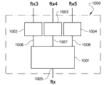
Figure 10 illustrates with being arranged to an example from 1 minute 3 separator 1000 of the second power splitter 1001 of the radio sector signal of Tx chain in 1005 receptions of power splitter input.Radio sector signal operates in total transmission band ftx.The second power splitter is separated into first 1006, second portion 1007 and third part 1008 by radio sector signal.First 1006 is arranged to receive at the input of the 3rd filter 1002, and second portion 1007 is arranged to receive at the input of the 4th filter 1003, and third part 1008 is arranged to receive at the input of the 5th filter 1004.The first filter 1002 is arranged to carry separated radio sector signal, and also referred to as subsignal, this subsignal is arranged to operate in the 3rd sub-band ftx3.The second filter 1003 is arranged to carry separated radio sector signal, and also referred to as subsignal, this subsignal is arranged to operate in the 4th sub-band ftx4.The 3rd filter 1004 is arranged to carry separated radio sector signal, and also referred to as subsignal, this subsignal is arranged to operate in the 5th sub-band ftx5.Sub-band is all in total transmission band ftx.For example, ftx can be 700-800 MHz, and ftx3 is 700-733 MHz, and ftx4 is 733-766 MHz, and ftx5 is 766-800 MHz.
1 minute 2 separator and 1 minute 3 separator also can be according to principle of reciprocity work, that is, in Tx pattern, the input of separator becomes the output in Rx pattern, and the output in Tx pattern becomes the input in Rx pattern.This means as by Figure 16 a with the same shown in 16b, separator also can be used in Rx pattern.This filter function that also means separator is according to reciprocity work, that is, they can filter the signal entering from the arbitrary end of filter.
Figure 11 illustrates according to the first ios dhcp sample configuration IOS DHCP of a MSN of the first example in above-mentioned table and as the node 800 as described in associated with Fig. 8.All three switch block 821-823 are in A position time, and the arrangement of components of a MSN 810 becomes following configuration:
● the power amplifier that the first subpath p11 and the first switch/combiner parts 811 for the first path p1 of the first radio sector signal s1 through the first path are connected to a Tx chain Tx1,
● the first subpath p22 and second switch/combiner unit 812 for the second path p2 of the second radio sector signal s2 through the second path are connected to the power amplifier for the 2nd Tx chain Tx2, and
● the first subpath p33 and the 3rd switch/combiner parts 813 for the Third Road footpath p3 of the 3rd radio sector signal s3 through Third Road footpath are connected to the power amplifier for the 3rd Tx chain Tx3.
The configuration of Figure 11 makes each Tx chain be arranged to operate in total transmission band ftx.This configuration is applicable to the heavy traffic in all three sectors.
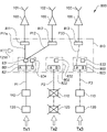
Figure 12, according to the 3rd example in upper table, illustrates the second ios dhcp sample configuration IOS DHCP of a MSN.Figure 12 illustrates as the node 800 as described in associated with Fig. 8.The first switch block 821 is when B position, and Tx base band and the Tx radio of the 2nd Tx chain are arranged to close, and the 3rd switch block 823 is arranged to when A position, and the arrangement of components of a MSN 810 becomes following configuration:
● the first path p1 for the first radio sector signal s1 is arranged to be connected to the one 1 minute 2 separator member 831, the one 1 minute 2 separator member are arranged to the first path p1 with the first radio sector signal s1 to be separated into the second subsignal s11a(and to be arranged in the first sub-band ftx1, operate after being arranged to be arranged to filter in the one 1 minute 2 separator member 831) the second subpath p11a and being arranged to the 3rd subsignal s12(of the first path p1 in the second sub-band ftx2, operate after being arranged to filter in the one 1 minute 2 separator member 831) the 3rd subpath p12 in the first path, two sub-frequency bands are arranged to operate in total transmission band ftx,
● the second subpath p11a of the first path p1 is arranged to be connected to through the first switch/combiner parts 811 power amplifier of a Tx chain Tx1,
● the 3rd subpath p12 of the first path p1 is arranged to be connected to through second switch/combiner unit 812 power amplifier of the 2nd Tx chain Tx2, and
● for the Third Road footpath p3 of the 3rd radio sector signal s3, be arranged to the power amplifier that the first subpath p33 and the 3rd switch/combiner parts 813 through Third Road footpath p3 are connected to the 3rd Tx chain Tx3.
The configuration of Figure 12 makes a Tx chain be arranged to operate in the first sub-band ftx1, and the power amplifier of the 2nd Tx chain operates in the second sub-band ftx2, and the 3rd Tx chain operates in total transmission band ftx.This configuration is applicable to low traffic and the heavy traffic in the 3rd sector in the first and second sectors.In this configuration, can close a base band and a radio to reduce power consumption.
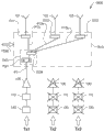
Figure 13, according to the 5th example in upper table, illustrates the 3rd ios dhcp sample configuration IOS DHCP of a MSN.Figure 13 illustrates as the node 800 as described in associated with Fig. 8.The first switch block 821 is in C position time, and Tx base band and the Tx radio of the second and the 3rd Tx chain are arranged to close, and the arrangement of components of a MSN 810 becomes following configuration:
● a first path for a first sector of a radio signal s1 p1 arranged to be connected to a first member 834 of the separator 3, a first separator member 5 to be arranged with a first sector of a radio signal s1 the first path p1 is separated into a fourth sub-signal with a first radio section s11b signal s1 (arranged to be disposed in a first one of the three filter separator member 834, the operation in the third sub-band ftx3) p11b fourth sub-path and the first path p1 s12a fifth sub-signal with a first radio section signal s1 (arranged in the filter is arranged in a first member 834 of the separator 3 in the fourth the fifth sub-band sub-path p12a ftx4 operating) the first path p1 and a sixth sub-signal with a first radio section s13 signal s1 (arranged to be disposed in a first separator member 834 5 after the filtering operation in the fifth subband ftx5) sixth sub-path of the first path p1 and p13, all three subbands ftx3-ftx5 arranged to operate in the total transmission band ftx,
● the 4th subpath p11b of the first path p1 is arranged to be connected to through the first switch/combiner parts 811 power amplifier of a Tx chain Tx1,
● the 5th subpath p12a of the first path p1 is arranged to be connected to through second switch/combiner unit 812 power amplifier of the 2nd Tx chain Tx2, and
● the 6th subpath p13 of the first path p1 is arranged to be connected to through the 3rd switch/combiner parts 813 power amplifier of the 3rd Tx chain Tx3.
The configuration of Figure 13 makes the power amplifier of a Tx chain be arranged to operate in the 3rd sub-band ftx3, and the power amplifier of the 2nd Tx chain operates in the 4th sub-band ftx4, and the power amplifier of the 3rd Tx chain operates in the 5th sub-band ftx5.This configuration is applicable to the low traffic in all three sectors.In this configuration, can close two base band and two radio to reduce power consumption.
When Figure 14 illustrates a MSN and is arranged in after power amplifier for the another example of the configuration possibility of a MSN.Node 1400 comprises three Rx chains and three Tx chains, a Tx1, the 2nd Tx2 and the 3rd Tx3.Rx chain is not shown in Figure 14.Tx chain is arranged to operate in first, second, and third sector of the correspondence first, second, and third radio sector signal s1-s3 with being arranged to generate in Tx chain, wherein, each radio sector signal s1-s3 is arranged to operate in total transmission band ftx, and is arranged through first, second, and third path p1-p3 forwarding.As in the basic configuration of Fig. 4, the one MSN 1410 arranges across all Tx chains after power amplifier, and comprise the 5th sef-adapting filter and the separator member 1401 with input and output, its output is connected to the 4th, the 5th and the 6th switch/combiner parts 1411-1413 input one of at least.The output of each switch/combiner parts is directly or indirectly connected to fan antenna.Sef-adapting filter and separator member comprise the 4th switch block 1421 and the 21 minute 3 separator member 1434.Separator member comprises separation and filter function.The 4th switch block 1421 is arranged to receive the radio sector signal from a Tx chain Tx1, the 5th switch/combiner parts 1412 are arranged to receive the radio sector signal from the 2nd Tx chain Tx2, and the 6th switch/combiner parts 1413 are arranged to receive the radio sector signal from the 3rd Tx chain Tx3.The 4th switch block and the 5th and the 6th switch/combiner parts are arranged to:
● will comprise that the antenna sector signal from the radio sector signal of its corresponding Tx chain is directly or indirectly forwarded to the fan antenna of corresponding Tx chain, the 4th switch block also forwards radio sector signals through institute's four switch/combiner parts (1411), or
● the antenna sector signal that comprises separated radio sector signal is directly or indirectly forwarded to each fan antenna through the 21 minute 3 separator member (1434) and switch/combiner parts,
The 4th switch block has two position: A and B.
Figure 15 illustrates the 4th switch block the 1421, the 1521st, and in B position, and the Tx base band of the second and the 3rd Tx chain, Tx radio and power amplifier be while being arranged to close, as the 4th ios dhcp sample configuration IOS DHCP of a MSN in the node as described in associated with Figure 14.The assembly of the one MSN 1510 thereby be arranged to following configuration:
● the first path p1 sector signal s1 for the first radio via a fourth switch means arranged to connect to a 5 second separator member 1534, a second separator member 5 is arranged with the first radio the first path p1 is separated into sector signal s1 s11c seventh sub-signal with a first radio section signal (to be arranged in a filter disposed in a second separator 5 in 1534 after the sixth subband ftx6 seventh Son path p11c in operation) and the first path p1 eighth child with a first radio signal s12b sector signal (arranged after being arranged to filter the second one of three in the first separator 1534 seven bands ftx7 operating) subpath p12b eighth and ninth first path p1 sub-signal s13a with the first path p1 (arranged in the filter is arranged in the second a minute after 3 splitter 1534 ftx8 operation in the eighth sub-band) path of the ninth sub-sector of the first radio signal, p13a, all three subbands ftx6-ftx8 arranged to operate in the total transmission band ftx,
● the 7th subpath p11c in the first path, be arranged to directly or indirectly be connected to through the 4th switch/combiner parts 1511 the first fan antenna 101 of a Tx chain Tx1,
● the 8th subpath p12b in the first path, be arranged to directly or indirectly be connected to through the 5th switch/combiner parts 1512 the second fan antenna 102 of the 2nd Tx chain Tx2, and
● the 9th subpath p13a in the first path, is arranged to be connected to through the 6th switch block 1513 the 3rd fan antenna 103 of the 3rd Tx chain Tx3
Make thus the first fan antenna 101 of a Tx chain be arranged to operate in the 6th sub-band ftx6, the second fan antenna 102 of the 2nd Tx chain operates in the 7th sub-band ftx7, and the 3rd fan antenna 103 of the 3rd Tx chain operates in the 8th sub-band ftx8.This configuration is applicable to the low traffic in all three sectors.
The 4th switch block 1421 is in A position time, and the 4th switch block is directly connected to the input of the 4th switch/combiner parts 1411, and the output of the 4th switch/combiner is directly or indirectly connected to its corresponding fan antenna.Therefore the radio sector signal of the one Tx chain Tx1 can be arranged to be forwarded to its corresponding fan antenna.As shown in figure 14, the radio sector signal of the second and the 3rd Tx chain Tx2 and Tx3 can be arranged to directly or indirectly through its corresponding switch/combiner parts, directly be forwarded to its corresponding fan antenna, this be because second and the power amplifier of the 3rd Tx chain can be directly connected to for the 5th of Tx2 and open at/combiner 1412 with for the input of the 6th switch/combiner parts 1413 of Tx3.Subsequently, directly or indirectly by the 5th and the output of the 6th switch/combiner parts be connected to its corresponding fan antenna.In this configuration, therefore all three radio sector signals can be arranged to be forwarded to its corresponding fan antenna, and each Tx chain can be arranged to operate in total transmission band ftx.This configuration is applicable to the heavy traffic in all three sectors.
Above for the ios dhcp sample configuration IOS DHCP shown in the MSN in Tx pattern also can be used in Rx pattern first or the configuration of the 2nd MSN.
In a word, the first component MSN 301,401,510,610,710,810,1410,1510 for switch and FL-network function arranged across all Tx chains before or after power amplifier 100.The one MSN comprise there is at least one sef-adapting filter of input and output and separator member 501-503,601-606,801-803,1401,1501, its output is connected to the input of at least one switch/combiner parts 511-513,611-613,811-813,1411-1413 and 1511-1513.The one MSN is arranged to directly or indirectly receive at least one the radio sector signal from least one Tx chain at the input of its corresponding sef-adapting filter and separator member, and from an antenna sector signal of output output of switch/combiner parts described in each, antenna sector signal comprises:
● from the radio sector signal of its corresponding Tx chain, radio sector signal is arranged to operate in total transmission band ftx, or
● from the separated radio sector signal of any Tx chain, separated radio sector signal is arranged to operate in a part of total transmission band tx,
The separation of radio sector signal allows a radio sector signal to be fed to the fan antenna in more than one sector, and each sector has at least one fan antenna.
Figure 16 a illustrates by node 1600, example of the present invention while realizing in FDD system in Tx and Rx pattern, node 1600 has a MSN 1610 who arranges across three Tx chain Tx1-Tx3 after power amplifier PA 100 and the 2nd MSN 1620 arranging across three Rx chain Rx1-Rx3 before low noise amplifier LNA 140.Node also comprises three fan antenna 101-103, the different sectors of each antenna cover in space.Each fan antenna is connected to Tx/Rx switch 130, and this switch arrangement becomes a MSN 1610 in Tx pattern and the 2nd MSN 1620 in Rx pattern that fan antenna is switched to Tx or Rx chain.
In the example of Figure 16 a, a MSN 1610 is according to the example arrangement of describing in Figure 15, that is, Tx2 and Tx3 close, and is separated into three subsignals from the radio sector signal s1 of Tx1, and each subsignal is fed to respective sector antennas.This configuration is applicable to the low traffic in all three sectors.
The 2nd MSN 1620 configuration as a MSN 1610 completely in the example of Figure 16 a, and be conventionally arranged to directly or indirectly receive an antenna sector signal from each fan antenna 101-103.In the example of Figure 16 a, each antenna sector signal is arranged to indirectly through Tx/Rx switch, receive at the output of its corresponding switch/combiner parts, and directly export from the input of the first sef-adapting filter and separator member 1501 a radio sector signal to a Rx chain Rx1 who comprises three separate antenna sector signals, signal of each fan antenna, in the example of Figure 16 a, each fan antenna covers different sectors.Each separate antenna sector signals is arranged to operate in a part of total frequency acceptance band frx, and three signals cover complete frequency band frx together.Separated therefore permission of antenna sector signal is combined into a radio sector signal from three separate antenna sector signals of different sectors in sef-adapting filter and separator member 1501.This means that Rx chain Rx2 and Rx3 can close, and therefore the 2nd MSN is applicable to the low traffic in all three sectors.
Figure 16 b illustrates by node 1670, example of the present invention while realizing in TDD system in Tx and Rx pattern, node 1670 has after power amplifier PA 100 across all three Tx chain Tx1-Tx3 and the MSN 1610 that arranged across all three Rx chain Rx1-Rx3 before low noise amplifier LNA 140.Node also comprises three fan antenna 101-103, the different sectors of each antenna cover in space.Each fan antenna is connected to Tx or Rx chain through a MSN 1610 and Tx-Rx switch 1680.
In the example of Figure 16 b, a MSN 1610 is according to the example arrangement of describing in Figure 15, that is, Tx2 and Tx3 close, and is separated into three subsignals from the radio sector signal of Tx1, and each subsignal is fed to respective sector antennas.This configuration is applicable to the low traffic in all three sectors.
A MSN 1610 in the example of Figure 16 b is also arranged to directly receive an antenna sector signal from each fan antenna.Each antenna sector signal is arranged to receive at the output of its corresponding switch/combiner parts, and indirectly through Tx/Rx switch 1680, from the input of described sef-adapting filter and separator member, to a Rx chain Rx1, export a radio sector signal, radio sector signal comprises three separate antenna sector signals from three fan antennas in different sectors, each separate antenna sector signals is arranged to operate in a part of total frequency acceptance band frx, and three separate antenna sector signals cover complete frequency band frx together.Separated therefore permission of antenna sector signal is combined into a radio sector signal from three separate antenna sector signals of different sectors in sef-adapting filter and separator member 1510.This means that Rx chain Rx2 and Rx3 can close, and therefore a MSN is applicable to the low traffic in all three sectors for Tx pattern and Rx pattern in the example of Figure 16 b.
For other configuration of MSN described in Tx pattern can be similar to the description for the realization of Rx pattern MSN according to the Tx pattern example of Figure 15 above, also in Rx pattern, realize.
Conventionally, when node is realized in FDD system, for the second component MSN 1620 of switch and FL-network function, before or after low noise amplifier 140, across all Rx chains, arrange.The 2nd MSN comprise there is at least one sef-adapting filter of input and output and separator member 501-503,601-606,801-803,1401,1501, its output is connected to the input of at least one switch/combiner parts 511-513,611-613,811-813,1411-1413,1511-1513.The 2nd MSN is arranged to directly or indirectly through Tx/Rx switch, receive an antenna sector signal from each fan antenna.Each antenna sector signal is arranged to receive at the output of its corresponding switch/combiner parts, and from the input of sef-adapting filter described at least one and separator member to a radio sector signal of its corresponding Rx chain output, each radio sector signal comprises:
● from the antenna sector signal of its corresponding fan antenna, antenna sector signal is arranged to operate in total frequency acceptance band frx, or
● from least two separate antenna sector signals of different fan antennas in different sectors, each separate antenna sector signals is arranged to operate in a part of total frequency acceptance band frx,
The separation of antenna sector signal allows in sef-adapting filter and separator member 501-503,601-606,801-803,1401,1501, to be combined into a radio sector signal from least two separate antenna sector signals of different sectors.This radio sector signal preferably covers total frequency acceptance band frx.The different piece of separate antenna sector signals is unnecessary adds up total frequency acceptance band frx, and therefore frequency part sum can be less than frx.
Conventionally, when node is realized in TDD system, for the first component MSN 1610 of switch and FL-network function, after power amplifier 100 and before low noise amplifier 140, across all Tx and Rx chain, arrange.The one MSN 1610 is arranged to directly receive an antenna sector signal from each fan antenna.Each antenna sector signal is arranged to receive at the output of its corresponding switch/combiner parts 1511, and the input from sef-adapting filter described at least one and separator member, indirectly through Tx/Rx switch 1680, to its corresponding Rx chain, export a radio sector signal, each radio sector signal comprises:
● from the antenna sector signal of its corresponding fan antenna, antenna sector signal is arranged to operate in total frequency acceptance band frx, or
● from least two separate antenna sector signals of different fan antennas in different sectors, each separate antenna sector signals is arranged to operate in a part of total frequency acceptance band frx,
The separation of antenna sector signal allows in sef-adapting filter and separator member 501-503,601-606,801-803,1401,1501, to be combined into a radio sector signal from least two separate antenna sector signals of different sectors.This radio sector signal preferably covers total frequency acceptance band frx.The different piece of separate antenna sector signals is unnecessary adds up total frequency acceptance band frx, and therefore frequency part sum can be less than frx.
Direction with reference to antenna sector signal is carried out the definition before or after low noise amplifier, that is, before low noise amplifier, be before antenna sector signal arrives low noise amplifier between low noise amplifier 140 and fan antenna 101-103.After low noise amplifier, be defined in antenna sector signal and passed through low noise amplifier afterwards between Rx radio 150 and low noise amplifier.When the present invention all realizes in FDD in Tx and two kinds of patterns of Rx, if Tx and Rx chain have public sections antenna, Tx/Rx switch is connected to fan antenna to switch between Tx and Rx pattern, and as shown in Figure 16 the same, when Tx and Rx pattern all realize in TDD, Tx/Rx switch arrangement is between MSN and Tx/Rx chain.
As more early mentioned, can response service load and configure sef-adapting filter and separator member and the switch/combiner parts of the 2nd MSN, can minimize the radio sector signal of informational needs and the quantity of Rx chain forwarding from all antenna sectors signal with respect to business load thus.This can complete by the traffic load information that is arranged to receive at the control inputs 1660 to the 2nd MSN.By the processing unit in the 2nd MSN, the 2nd MSN is arranged through processing unit and traffic load information and controls sef-adapting filter and separator member 501-503,601-606,801-803,1401,1501 and the configuration of switch/combiner parts 511-513,611-613,811-813,1411-1413,1511-1513, to minimize the quantity of radio sector signal.
Traffic load information can be arranged to from wireless communication system or from external source, be fed to the control inputs 1660 of the 2nd MSN.
By the manual adjustment of sef-adapting filter and separator member and switch/combiner parts, arrange sef-adapting filter and separator member 501-503,601-606,801-803,1401,1501 and the configuration of switch/combiner parts 511-513,611-613,811-813,1411-1413,1511-1513, to minimize the quantity of radio sector signal with respect to business load.
A part of or complete Tx and/or Rx chain can be arranged to by means of the processing unit from the 2nd MSN to the control signal of Tx or Rx chain or manually or external control signal be that each minimizing of radio sector signal is closed.
Each MSN comprises control inputs.This has passed through label 550 in Fig. 5, in Fig. 7, by label 750, in Fig. 8, by label 850, in Figure 11, pass through label 1150, in Figure 12-15, by label 1250-1550, in Figure 16 a, by label 1650 and in Figure 16 b, by label 1660, illustrate.
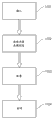
Figure 17 is illustrated in an example that reduces the method for the present invention of power consumption in the node (500,600,800,1400,1500,1600) as described in claim 1-18 any one, wherein:
● before or after power amplifier (100), across all Tx chains, insert a MSN(301,401,510,610,710,810,1410,1510,1610) and/or before or after low noise amplifier (140) across all Rx chains, insert the 2nd MSN (1620), or
● power amplifier (100) afterwards and low noise amplifier (140) across all Tx and Rx chain, insert (1701) the one MSN before
And wherein, traffic load information is to first and/or the control inputs (550 of the 2nd MSN, 750, 850, 1150, 1250, 1350, 1450, 1550, 1650, 1660) receive (1702), and by first and/or the processing unit of the 2nd MSN or manually, the first and/or the 2nd MSN configuration (1703) sef-adapting filter and separator member and switch/combiner parts, to minimize the quantity of radio sector signal, thus by means of from first and/or the processing unit of the 2nd MSN to the control signal of Tx and Rx chain or manually or external control signal, permission needs and/or forwarding is closed (1704) complete or part Tx and/or Rx chain from each minimizing of the radio sector signal of the informational needs of all antenna sectors signal to all fan antennas for supply antenna sector signal with respect to business load.
The present invention also provides a kind of wireless communication system that comprises node as described in claim 1-18 any one.Wireless communication system can be for example GSM(global system for mobile communications) or LTE(Long Term Evolution) system.
The invention is not restricted to above-described embodiment and example, but can within the scope of the claim of enclosing, freely change.
Claims (20)
1. one kind comprises the node (500 using in the wireless communication system of at least two Tx chains and at least two Rx chains, 600, 800, 1400, 1500, 1600), each Tx chain and each Rx chain comprise antenna end and radio end, described antenna end is directly or indirectly connected to fan antenna (101, 102, 103), each fan antenna is arranged in certain sector, operate in space, each Tx chain comprises the parts for Tx base band (120) and Tx radio (110) and power amplifier (100) PA being connected in series, and described power amplifier is directly or indirectly connected to a fan antenna, each Rx chain comprises the parts for Rx base band (160) and Rx radio (150) and low noise amplifier (140) LNA being connected in series, and described low noise amplifier is directly or indirectly connected to a fan antenna, each Tx chain is arranged to operate in total transmission band ftx, and each Rx chain is arranged to operate in total frequency acceptance band frx, it is characterized in that the first component MSN(301 for switch and FL-network function, 401, 510, 610, 710, 810, 1410, 1510, 1610) before or after described power amplifier (100), across all Tx chains, arrange, a described MSN comprises at least one sef-adapting filter and the separator member (501-503 with input and output, 601-606, 801-803, 1401, 1501), described in it, output is connected at least one switch/combiner parts (511-513, 611-613, 811-813, 1411-1413, input 1511-1513), a described MSN is arranged to directly or indirectly receive at least one the radio sector signal from least one Tx chain at the described input of its corresponding sef-adapting filter and separator member, and the antenna sector signal of described output output from switch/combiner parts described in each, described antenna sector signal comprises:
● from the radio sector signal of its corresponding Tx chain, described radio sector signal is arranged to operate in described total transmission band ftx, or
● from the separated radio sector signal of any described Tx chain, described separated radio sector signal is arranged to operate in a part of described total transmission band ftx,
The described separated of radio sector signal allows a radio sector signal to be fed to the fan antenna in more than one sector, and each sector has at least one fan antenna.
2. node as claimed in claim 1, it is characterized in that response service load and configure described sef-adapting filter and separator member and the described switch/combiner parts of a described MSN, can minimize with respect to business load the quantity of the radio sector signal that antenna sector signal provision is needed to all fan antennas thus.
3. node as claimed in claim 1 or 2, it is characterized in that across all Rx chains, arranging before or after described low noise amplifier (140) for the second component MSN (1620) of switch and FL-network function, described the 2nd MSN comprises at least one sef-adapting filter and the separator member (501-503 with input and output, 601-606, 801-803, 1401, 1501), described in it, output is connected at least one switch/combiner parts (511-513, 611-613, 811-813, 1411-1413, input 1511-1513), described the 2nd MSN is arranged to directly or indirectly through Tx/Rx switch, receive an antenna sector signal from each fan antenna, each antenna sector signal is arranged to receive at the described output of its corresponding switch/combiner parts, and from described sef-adapting filter and separator member described input one of at least to a radio sector signal of its corresponding Rx chain output, each radio sector signal comprises:
● from the antenna sector signal of its corresponding fan antenna, described antenna sector signal is arranged to operate in described total frequency acceptance band frx, or
● from least two separate antenna sector signals of different fan antennas in different sectors, each separate antenna sector signals is arranged to operate in a part of described total frequency acceptance band frx,
Described separated permission of antenna sector signal is combined into a radio sector signal from least two separate antenna sector signals of different sectors in described sef-adapting filter and separator member (501-503,601-606,801-803,1401,1501).
4. node as claimed in claim 1 or 2, it is characterized in that across all Tx and Rx chain, arranging before with described low noise amplifier (140) afterwards at described power amplifier (100) for the first component MSN (1610) of switch and FL-network function, a described MSN (1610) is arranged to directly from each fan antenna, receive an antenna sector signal, each antenna sector signal is arranged to receive at the described output of its corresponding switch/combiner parts (1511), and indirectly through Tx/Rx switch (1680) from described sef-adapting filter and separator member described input one of at least to a radio sector signal of its corresponding Rx chain output, each radio sector signal comprises:
● from the antenna sector signal of its corresponding fan antenna, described antenna sector signal is arranged to operate in described total frequency acceptance band frx, or
● from least two separate antenna sector signals of different fan antennas in different sectors, each separate antenna sector signals is arranged to operate in a part of described total frequency acceptance band frx,
Described separated permission of antenna sector signal is combined into a radio sector signal from least two separate antenna sector signals of different sectors in described sef-adapting filter and separator member (501-503,601-606,801-803,1401,1501).
5. the node as described in claim 3 or 4, it is characterized in that response service load and configure described sef-adapting filter and separator member and the described switch/combiner parts of described the 2nd MSN, can minimize the radio sector signal of informational needs and the quantity of Rx chain forwarding from all antenna sectors signal with respect to business load thus.
6. the node as described in claim 1-5 any one, is characterized in that described indirect connection realizes by Tx/Rx switch.
7. the node as described in claim 2 or 5, it is characterized in that described traffic load information is arranged to described first and the control inputs (550 of described the 2nd MSN, 750, 850, 1150, 1250, 1350, 1450, 1550, 1650, 1660) receive, and be by described first and described the 2nd MSN in processing unit, described first and described the 2nd MSN is arranged through described processing unit and described traffic load information is controlled described sef-adapting filter and separator member (501-503, 801-803, 1401, 1501) and described switch/combiner parts (511-513, 811-813, 1411-1413, described configuration 1511-1513), to minimize the quantity of radio sector signal.
8. node as claimed in claim 7, it is characterized in that described traffic load information is arranged to be fed to described first and the described control inputs (550 of described the 2nd MSN from described wireless communication system or from external source, 750,850,1150,1250,1350,1450,1550,1650,1660).
9. the node as described in claim 1-6 any one, it is characterized in that by the manual adjustment of described sef-adapting filter and separator member and described switch/combiner parts, arrange described sef-adapting filter and separator member (501-503,601-606,801-803,1401,1501) and described switch/combiner parts (511-513,611-613,811-813,1411-1413,1511-1513) described configuration, to minimize the quantity of radio sector signal with respect to business load.
10. the node as described in claim 1-9 any one, it is characterized in that a part or complete Tx and/or Rx chain can be arranged to by means of from described first or the described processing unit of described the 2nd MSN to the control signal of described Tx and/or Rx chain or manually or external control signal be that each minimizing of radio sector signal is closed.
11. the node as described in claim 1-10 any one, it is characterized in that representing the sum for the fan antenna of all sectors at N, and when M represents Tx/Rx chain in the sum of Tx chain in FDD application or the sum of Rx chain or TDD application total, there are M sef-adapting filter and separator member (501-503, 601-606, 701, 801-803, 1401, 1501) and N switch/combiner parts (511-513, 611-613, 702, 811-813, 1411-1413, 1511-1513), wherein, M >=N, and the quantity of exporting at the described output of described sef-adapting filter and separator member equals N, and the quantity of inputting at the described input of switch/combiner parts equals M, allow thus each sef-adapting filter and separator member to be connected to each switch/combiner parts.
12. the node as described in claim 1-11 any one, it is characterized in that comprising three Rx chains and three Tx chains, the one Tx1, the 2nd Tx2 and the 3rd Tx3, described Tx chain is arranged in the correspondence first with being arranged to generate in described Tx chain, first of the second and the 3rd radio sector signal s1-s3, operation in the second and the 3rd sector, wherein each radio sector signal s1-s3 is arranged to operate in total transmission band ftx, and be arranged through first, second and Third Road footpath (p1-p3) forward, a described MSN(301, 401, 510, 610, 710, 810, 1410, 1510, 1610) before described power amplifier, across all Tx chains, arrange, and comprise and respectively there is first of input and output, the second and the 3rd sef-adapting filter and separator member (501-503, 601-606, 801-803, 1401, 1501), described in it, output is connected to first, the second and the 3rd switch/combiner parts (511-513, 611-613, 811-813, 1411-1413, 1511-1513) input one of at least, and the described output of each switch/combiner parts is directly or indirectly connected to fan antenna through described power amplifier, wherein said sef-adapting filter and separator member comprise respectively first, the second and the 3rd switch block (821-823, 1421, 1521) and the first, second and the 31 minute 2 (1-to-2) separator member (831-833), described the first sef-adapting filter and separator member also comprise the one 1 minute 3 (1-to-3) separator member (834), each separator member comprises separation and filter function, and wherein said the first switch block receives the first radio sector signal from a described Tx chain, described second switch parts receive the second radio sector signal from described the 2nd Tx chain, and described the 3rd switch block receives the 3rd radio sector signal from described the 3rd Tx chain, each switch block is arranged to:
● through switch/combiner parts and power amplifier, the antenna sector signal that is included in the radio sector signal in the described Tx chain of described switch block is directly or indirectly forwarded to fan antenna, or
● through switch/combiner parts and power amplifier, will be included in described 1 minute 2 separator member or directly or indirectly be forwarded to fan antenna at the antenna sector signal of the separated radio sector signal of described 1 minute 3 separator member, described separated radio sector signal is also at least two Tx chain repeatings
Described the first switch block has three position: A, B and C, and the described second and the 3rd switch block has two position A and B.
13. node as claimed in claim 12, is characterized in that all three switch blocks (821-823) are when described A position, a described MSN(301,401,510,610,710,810,1410,1510,1610) arrangement of components become following configuration:
● the described power amplifier that the first subpath (p11) and described the first switch/combiner parts (811) for described the first path (p1) of described the first radio sector signal s1 through described the first path are connected to a described Tx chain Tx1
● the first subpath (p22) and described second switch/combiner unit (812) for described the second path (p2) of described the second radio sector signal s2 through described the second path are connected to the described power amplifier for described the 2nd Tx chain Tx2, and
● the first subpath (p33) and described the 3rd switch/combiner parts (813) for the described Third Road footpath (p3) of described the 3rd radio sector signal s3 through described Third Road footpath are connected to the described power amplifier for described the 3rd Tx chain Tx3
Make thus each Tx chain be arranged to operate in described total transmission band ftx, this configuration is applicable to the heavy traffic in all three sectors.
14. nodes as claimed in claim 12, is characterized in that described the first switch block (821) is in described B position, when the described Tx base band of described the 2nd Tx chain and Tx radio are arranged to close, and described the 3rd switch block (823) is arranged to when described A position, a described MSN(301,401,510,610,710,810,1410,1510,1610) arrangement of components becomes following configuration:
● described the first path (p1) for described the first radio sector signal s1 is arranged to be connected to described the one 1 minute 2 separator member (831), described the one 1 minute 2 separator member are arranged to described the first path (p1) with described the first radio sector signal s1 to be separated into second subpath (p11a) in described the first path (p1) of the second subsignal s11a with the 3rd subpath (p12) in the first path of the 3rd subsignal s12, the second subsignal s11a is arranged in the first sub-band ftx1, operate after being arranged to filter in described the one 1 minute 2 separator member (831), the 3rd subsignal s12 is arranged in the second sub-band ftx2, operate after being arranged to filter in described the one 1 minute 2 separator member (831), two sub-frequency bands are arranged to operate in described total transmission band ftx,
● described second subpath (p11a) in described the first path (p1) is arranged to be connected to through described the first switch/combiner parts (811) the described power amplifier of a described Tx chain Tx1,
● described the 3rd subpath (p12) in described the first path (p1) is arranged to be connected to through described second switch/combiner unit (812) the described power amplifier of described the 2nd Tx chain Tx2, and
● the described Third Road footpath (p3) for described the 3rd radio sector signal s3 is arranged to the described power amplifier that the first subpath (p33) and described the 3rd switch/combiner parts (813) through described Third Road footpath (p3) are connected to described the 3rd Tx chain Tx3
Make thus a described Tx chain be arranged to operate in described the first sub-band ftx1, the described power amplifier of described the 2nd Tx chain operates in described the second sub-band ftx2, and described the 3rd Tx chain operates in described total transmission band ftx, this configuration is applicable to low traffic in described the first and second sectors and the heavy traffic in described the 3rd sector.
15. nodes as claimed in claim 12, it is characterized in that described the first switch block (821) is in described C position, when the described Tx base band of the described second and the 3rd Tx chain and Tx radio are arranged to close, a described MSN(301,401,510,610,710,810,1410,1510,1610) arrangement of components becomes following configuration:
● described the first path (p1) for described the first radio sector signal s1 is arranged to be connected to described the one 1 minute 3 separator member (834), described the one 1 minute 3 separator member are arranged to described the first path (p1) with described the first radio sector signal s1 to be separated into the 4th subpath (p11b) in described the first path (p1) of the 4th subsignal s11b of described the first radio sector signal s1 with the 5th subpath (p12a) in described the first path (p1) of the 5th subsignal s12a of described the first radio sector signal s1 and with the 6th subpath (p13) in described the first path (p1) of the 6th subsignal s13 of described the first radio sector signal s1, the 4th subsignal s11b is arranged in the 3rd sub-band ftx3, operate after being arranged to filter in described the one 1 minute 3 separator member (834), the 5th subsignal s12a is arranged in the 4th sub-band ftx4, operate after being arranged to filter in described the one 1 minute 3 separator member (834), the 6th subsignal s13 is arranged in the 5th sub-band ftx5, operate after being arranged to filter in described the one 1 minute 3 separator member (834), all three sub-frequency bands ftx3-ftx5 are arranged to operate in described total transmission band ftx
● described the 4th subpath (p11b) in described the first path (p1) is arranged to be connected to through described the first switch/combiner parts (811) the described power amplifier of a described Tx chain Tx1,
● described the 5th subpath (p12a) in described the first path (p1) is arranged to be connected to through described second switch/combiner unit (812) the described power amplifier of described the 2nd Tx chain Tx2, and
● described the 6th subpath (p13) in described the first path (p1) is arranged to be connected to through described the 3rd switch/combiner parts (813) the described power amplifier of described the 3rd Tx chain Tx3,
Make thus the described power amplifier of a Tx chain be arranged to operate in described the 3rd sub-band ftx3, the described power amplifier of described the 2nd Tx chain operates in described the 4th sub-band ftx4 and the described power amplifier of described the 3rd Tx chain operates in described five sub-band ftx5, and this configuration is applicable to the low traffic in all three sectors.
16. nodes as described in claim 1-11 any one, it is characterized in that comprising three Rx chains and three Tx chains, the one Tx1, the 2nd Tx2 and the 3rd Tx3, described Tx chain is arranged in the correspondence first with being arranged to generate in described Tx chain, first of the second and the 3rd radio sector signal s1-s3, operation in the second and the 3rd sector, wherein each radio sector signal s1-s3 is arranged to operate in total transmission band ftx, and be arranged through first, second and Third Road footpath (p1-p3) forward, a described MSN (1410) arranges across all Tx chains after described power amplifier, and comprise the 5th sef-adapting filter and the separator member (1401) with input and output, described in it, output is connected to the 4th, the the 5th and the 6th switch/combiner parts (1411-1413) input one of at least, and the described output of each switch/combiner parts is directly or indirectly connected to fan antenna, wherein said sef-adapting filter and separator member comprise the 4th switch block (1421) and the 21 minute 3 separator member (1434), described separator member comprises separation and filter function, and wherein said the 4th switch block (1421) is arranged to receive the radio sector signal from a described Tx chain (Tx1), described the 5th switch/combiner parts (1412) are arranged to receive the radio sector signal from described the 2nd Tx chain (Tx2), and described the 6th switch/combiner parts (1413) are arranged to receive the radio sector signal from described the 3rd Tx chain (Tx3), and described four switch blocks and the described the 5th and the 6th switch/combiner parts are arranged to:
● will comprise that the antenna sector signal from the radio sector signal of its corresponding Tx chain is directly or indirectly forwarded to the fan antenna of described corresponding Tx chain, described the 4th switch block also forwards described radio sector signal through described the 4th switch/combiner parts (1411), or
● the antenna sector signal that comprises separated radio sector signal is directly or indirectly forwarded to each fan antenna through described the 21 minute 3 separator member (1434) and switch/combiner parts,
Described the 4th switch block has two position: A and B.
17. nodes as claimed in claim 16, it is characterized in that at described the 4th switch block (1421,1521) be in described B position, and when the described Tx base band of the described second and the 3rd Tx chain, described Tx radio and described power amplifier are arranged to close, the described arrangement of components of a described MSN (1510) becomes following configuration:
● described the first path (p1) for described the first radio sector signal s1 is arranged to be connected to described the 21 minute 3 separator member (1534) through described the 4th switch block, described the 21 minute 3 separator member are arranged to described the first path (p1) with described the first radio sector signal s1 to be separated into the 7th subpath (p11c) in described the first path (p1) of the 7th subsignal s11c of described the first radio sector signal with the 8th subpath (p12b) in described the first path (p1) of the 8th subsignal s12b of described the first radio sector signal and with the 9th subpath (p13a) of described the first radio sector signal of the 9th subsignal s13a in described the first path (p1), the 7th subsignal s11c is arranged in the 6th sub-band ftx6, operate after being arranged to filter in described the 21 minute 3 separators (1534), the 8th subsignal s12b is arranged in the 7th sub-band ftx7, operate after being arranged to filter in described the 21 minute 3 separator member (1534), the 9th subsignal s13a is arranged in the 8th sub-band ftx8, operate after being arranged to filter in described the 21 minute 3 separator member (1534), all 3 sub-frequency bands ftx6-ftx8 are arranged to operate in described total transmission band ftx
● described the 7th subpath (p11c) in described the first path, be arranged to directly or indirectly be connected to through described the 4th switch/combiner parts (1511) described first fan antenna (101) of a described Tx chain (Tx1),
● described the 8th subpath (p12b) in described the first path, be arranged to directly or indirectly be connected to through described the 5th switch/combiner parts (1512) described second fan antenna (102) of described the 2nd Tx chain (Tx2), and
● described the 9th subpath (p13a) in described the first path, be arranged to be connected to through described the 6th switch block (1513) described the 3rd fan antenna (103) of described the 3rd Tx chain (Tx3),
Make thus described first fan antenna (101) of a Tx chain be arranged to operate in described the 6th sub-band ftx6, described second fan antenna (102) of described the 2nd Tx chain operates in described the 7th sub-band ftx7, and described the 3rd fan antenna (103) of described the 3rd Tx chain operates in described the 8th sub-band ftx8, this configuration is applicable to the low traffic in all three sectors.
18. nodes as described in claim 1-17 any one, it is characterized in that cutting apart described power amplifier and the wireless described parts of Tx at least one Tx chain at least two carrier wave parts, each carrier wave part operates in a part for described total transmission band, and each carrier wave is partly arranged to the radio sector signal of cutting apart in the described frequency range of described carrier wave part to be forwarded to a sef-adapting filter and separator member (601-606), and described sef-adapting filter and separator member are arranged to:
● by separated, cut apart radio sector signal and be forwarded to its corresponding switch/combiner parts (611-613), the wherein said radio sector signal of cutting apart is arranged to be combined into an antenna sector signal that comprises all carrier wave parts, described antenna sector signal layout is used for operating in described total transmission band ftx, or
● forward at least two " separating radio sector signals ", each " separating radio sector signal " is arranged to be forwarded to different switch/combiner, wherein described " the separating radio sector signal " from different carrier part is combined into a separate antenna sector signals that comprises all carrier wave parts, and described separate antenna sector signals is arranged for operating in a part of described total transmission band ftx.
19. 1 kinds of wireless communication systems that comprise node as described in claim 1-18 any one.
The method of 20. 1 kinds of reductions middle power consumption of node (500,600,800,1400,1500,1600) as described in claim 1-18 any one, is characterized in that:
● before or after described power amplifier (100), across all Tx chains, insert (1701) the one MSN(301,401,510,610,710,810,1410,1510,1610) and/or before or after described low noise amplifier (140) across all Rx chains, insert the 2nd MSN (1620), or
● at described power amplifier (100), across all Tx and Rx chain, insert (1701) the one MSN before with described low noise amplifier (140) afterwards,
And wherein traffic load information to the described control inputs (550 of the described first and/or the 2nd MSN, 750, 850, 1150, 1250, 1350, 1450, 1550, 1650, 1660) receive (1702), and the processing unit by the described first and/or the 2nd MSN or manually, the described first and/or the 2nd MSN configuration (1703) described sef-adapting filter and separator member and described switch/combiner parts, to minimize the quantity of radio sector signal, thus by means of the described processing unit from the described first and/or the 2nd MSN to the control signal of described Tx and Rx chain or manually or external control signal, permission needs and/or forwarding is closed (1704) complete or part Tx and/or Rx chain from each minimizing of the radio sector signal of the informational needs of all antenna sectors signal to all fan antennas for supply antenna sector signal with respect to business load.
Applications Claiming Priority (1)
| Application Number | Priority Date | Filing Date | Title |
|---|---|---|---|
| PCT/EP2011/060523 WO2012175133A1 (en) | 2011-06-22 | 2011-06-22 | Adaptive filtering architecture |
Publications (1)
| Publication Number | Publication Date |
|---|---|
| CN103621175A true CN103621175A (en) | 2014-03-05 |
Family
ID=44628006
Family Applications (1)
| Application Number | Title | Priority Date | Filing Date |
|---|---|---|---|
| CN201180071808.3A Pending CN103621175A (en) | 2011-06-22 | 2011-06-22 | Adaptive filtering architecture |
Country Status (4)
| Country | Link |
|---|---|
| US (1) | US9374778B2 (en) |
| EP (1) | EP2724591B1 (en) |
| CN (1) | CN103621175A (en) |
| WO (1) | WO2012175133A1 (en) |
Cited By (1)
| Publication number | Priority date | Publication date | Assignee | Title |
|---|---|---|---|---|
| CN105048109A (en) * | 2015-06-30 | 2015-11-11 | 南京理工大学 | Time modulation-based direction backtracking and self-zeroing common-aperture antenna array |
Families Citing this family (8)
| Publication number | Priority date | Publication date | Assignee | Title |
|---|---|---|---|---|
| US11122444B2 (en) * | 2012-11-09 | 2021-09-14 | Interdigital Patent Holdings, Inc. | Beamforming methods and methods for using beams |
| US9247326B2 (en) * | 2014-01-31 | 2016-01-26 | Google Inc. | Systems and methods for increasing bandwidth in a computer network |
| US10187137B2 (en) * | 2016-04-06 | 2019-01-22 | Qualcomm Incorporated | High power user equipment (HPUE) using coherently combined power amplifiers |
| US10567070B2 (en) * | 2017-04-02 | 2020-02-18 | Ahmad Jalali | Air to ground network for broadband access to aerial platforms |
| CN109660270A (en) * | 2018-11-21 | 2019-04-19 | 惠州Tcl移动通信有限公司 | A kind of method and mobile terminal reducing the deterioration of SGLTE coupling sensitivity |
| EP3949142A4 (en) * | 2019-03-26 | 2022-06-22 | Telefonaktiebolaget Lm Ericsson (Publ) | Interconnect in multiple-input multiple-output communication system |
| US11356127B2 (en) * | 2019-12-16 | 2022-06-07 | Hewlett Packard Enterprise Development Lp | Selective filtering for continuous 5 GHz and 6 GHz operation of a network device |
| US11476824B2 (en) | 2020-07-09 | 2022-10-18 | Hewlett Packard Enterprise Development Lp | Selective filtering for continuous 5 GHz and 6 GHz operation of a network device |
Family Cites Families (6)
| Publication number | Priority date | Publication date | Assignee | Title |
|---|---|---|---|---|
| US5548813A (en) * | 1994-03-24 | 1996-08-20 | Ericsson Inc. | Phased array cellular base station and associated methods for enhanced power efficiency |
| KR100528407B1 (en) * | 2000-08-03 | 2005-11-23 | 주식회사 케이엠더블유 | Apparatus and method for variable frequency allocation in wireless telecommunication system |
| CN100493264C (en) * | 2006-09-22 | 2009-05-27 | 华为技术有限公司 | Uplink and downlink signal merging method under sector discerption mode and base station system |
| US20080287163A1 (en) | 2007-05-17 | 2008-11-20 | Telefonaktiebolaget Lm Ericsson (Publ), | Method and apparatus for converting between a multi-sector, omni-base station configuration and a multi-sector base station configuration |
| EP2157811B1 (en) * | 2007-06-04 | 2016-05-04 | Fujitsu Limited | Radio base station device and radio resource connection switching method |
| US8626088B2 (en) * | 2009-04-08 | 2014-01-07 | Telefonaktiebolaget L M Ericsson (Publ) | Data communication scheduling |
-
2011
- 2011-06-22 CN CN201180071808.3A patent/CN103621175A/en active Pending
- 2011-06-22 WO PCT/EP2011/060523 patent/WO2012175133A1/en active Application Filing
- 2011-06-22 EP EP11729596.4A patent/EP2724591B1/en not_active Not-in-force
- 2011-06-22 US US14/127,195 patent/US9374778B2/en active Active
Cited By (2)
| Publication number | Priority date | Publication date | Assignee | Title |
|---|---|---|---|---|
| CN105048109A (en) * | 2015-06-30 | 2015-11-11 | 南京理工大学 | Time modulation-based direction backtracking and self-zeroing common-aperture antenna array |
| CN105048109B (en) * | 2015-06-30 | 2018-01-05 | 南京理工大学 | Direction backtracking and the shared aperture antenna battle array that returns to zero certainly based on time-modulation |
Also Published As
| Publication number | Publication date |
|---|---|
| EP2724591B1 (en) | 2017-03-01 |
| WO2012175133A1 (en) | 2012-12-27 |
| US20140119259A1 (en) | 2014-05-01 |
| US9374778B2 (en) | 2016-06-21 |
| EP2724591A1 (en) | 2014-04-30 |
Similar Documents
| Publication | Publication Date | Title |
|---|---|---|
| CN103621175A (en) | Adaptive filtering architecture | |
| US11018726B2 (en) | Radio-frequency front-end systems and devices | |
| JP6907289B2 (en) | Transmitter system, high frequency module and wireless device | |
| US9748992B2 (en) | Systems and methods for reducing filter insertion loss while maintaining out-of band attenuation | |
| AU2007353897B2 (en) | Method and apparatus for converting between a multi-sector, omni-base station configuration and a multi-sector base station configuration | |
| CN106575976B (en) | Systems and methods related to time and frequency division duplex protocols for wireless applications | |
| US11368179B2 (en) | Modulation partitioning and transmission via multiple antennas for enhanced transmit power capability | |
| US11855663B2 (en) | Broadband architectures for radio frequency front-ends | |
| JP2019528656A (en) | Multi-standard wireless switchable multiplexer | |
| CN105684367A (en) | Systems and methods related to carrier aggregation front-end module applications | |
| US20150085708A1 (en) | Carrier aggregation using multiple antennas | |
| US20220069850A1 (en) | Filter reuse in radio frequency front-ends | |
| EP2749123A2 (en) | Software configurable distributed antenna system and method for reducing uplink noise | |
| CN103548273B (en) | System and method for processing time division signal and frequency division signal | |
| CN109617558A (en) | Architecture and method relevant to double letter improved isolation in device path | |
| CN101877917A (en) | Remote radio unit | |
| EP2351233B1 (en) | Shared rf front-end module for cellular application | |
| US11050456B2 (en) | Radio frequency module and communication device | |
| KR102653890B1 (en) | A Radio Frequency Integrated Chip supporting carrier aggregation and an wireless communication apparatus including the same | |
| CN111726141A (en) | Antenna system based on same-frequency multi-system concurrence | |
| CN100388825C (en) | Signal loop device and base-station common antenna-feedback system using same | |
| EP2122744B1 (en) | An apparatus and a method for directing a received signal in an antenna system | |
| US20240120953A1 (en) | Tunable filter arrangement |
Legal Events
| Date | Code | Title | Description |
|---|---|---|---|
| PB01 | Publication | ||
| PB01 | Publication | ||
| C10 | Entry into substantive examination | ||
| SE01 | Entry into force of request for substantive examination | ||
| WD01 | Invention patent application deemed withdrawn after publication | ||
| WD01 | Invention patent application deemed withdrawn after publication |
Application publication date: 20140305 |