EP2394932B1 - Kapsel mit Anbruchzone - Google Patents
Kapsel mit Anbruchzone Download PDFInfo
- Publication number
- EP2394932B1 EP2394932B1 EP10306436.6A EP10306436A EP2394932B1 EP 2394932 B1 EP2394932 B1 EP 2394932B1 EP 10306436 A EP10306436 A EP 10306436A EP 2394932 B1 EP2394932 B1 EP 2394932B1
- Authority
- EP
- European Patent Office
- Prior art keywords
- capsule
- membrane
- annular
- central region
- resistance
- Prior art date
- Legal status (The legal status is an assumption and is not a legal conclusion. Google has not performed a legal analysis and makes no representation as to the accuracy of the status listed.)
- Active
Links
- 239000002775 capsule Substances 0.000 title claims description 139
- 239000012528 membrane Substances 0.000 claims description 57
- 238000000605 extraction Methods 0.000 claims description 52
- 239000000463 material Substances 0.000 claims description 45
- 239000000126 substance Substances 0.000 claims description 31
- 239000004033 plastic Substances 0.000 claims description 26
- 229920003023 plastic Polymers 0.000 claims description 26
- 239000007788 liquid Substances 0.000 claims description 22
- 230000002093 peripheral effect Effects 0.000 claims description 20
- 235000013361 beverage Nutrition 0.000 claims description 11
- IJGRMHOSHXDMSA-UHFFFAOYSA-N Atomic nitrogen Chemical compound N#N IJGRMHOSHXDMSA-UHFFFAOYSA-N 0.000 claims description 7
- 238000002360 preparation method Methods 0.000 claims description 4
- 229910052757 nitrogen Inorganic materials 0.000 claims description 3
- 230000002787 reinforcement Effects 0.000 claims 1
- 239000012530 fluid Substances 0.000 description 16
- 208000031968 Cadaver Diseases 0.000 description 14
- 230000000694 effects Effects 0.000 description 13
- 238000007789 sealing Methods 0.000 description 5
- 230000003014 reinforcing effect Effects 0.000 description 4
- 238000002955 isolation Methods 0.000 description 3
- 238000004519 manufacturing process Methods 0.000 description 3
- 239000004952 Polyamide Substances 0.000 description 2
- 229910052782 aluminium Inorganic materials 0.000 description 2
- XAGFODPZIPBFFR-UHFFFAOYSA-N aluminium Chemical compound [Al] XAGFODPZIPBFFR-UHFFFAOYSA-N 0.000 description 2
- 238000004040 coloring Methods 0.000 description 2
- 230000006835 compression Effects 0.000 description 2
- 238000007906 compression Methods 0.000 description 2
- 238000002347 injection Methods 0.000 description 2
- 239000007924 injection Substances 0.000 description 2
- 230000005012 migration Effects 0.000 description 2
- 238000013508 migration Methods 0.000 description 2
- 230000003647 oxidation Effects 0.000 description 2
- 238000007254 oxidation reaction Methods 0.000 description 2
- 239000002985 plastic film Substances 0.000 description 2
- 229920006255 plastic film Polymers 0.000 description 2
- 229920002647 polyamide Polymers 0.000 description 2
- 231100000701 toxic element Toxicity 0.000 description 2
- XLYOFNOQVPJJNP-UHFFFAOYSA-N water Substances O XLYOFNOQVPJJNP-UHFFFAOYSA-N 0.000 description 2
- 239000004411 aluminium Substances 0.000 description 1
- 230000004323 axial length Effects 0.000 description 1
- 230000004888 barrier function Effects 0.000 description 1
- 230000009286 beneficial effect Effects 0.000 description 1
- 230000015556 catabolic process Effects 0.000 description 1
- 239000012141 concentrate Substances 0.000 description 1
- 238000006731 degradation reaction Methods 0.000 description 1
- 238000009792 diffusion process Methods 0.000 description 1
- 239000000839 emulsion Substances 0.000 description 1
- 235000013305 food Nutrition 0.000 description 1
- 238000007373 indentation Methods 0.000 description 1
- 239000011261 inert gas Substances 0.000 description 1
- 230000014759 maintenance of location Effects 0.000 description 1
- 229910052751 metal Inorganic materials 0.000 description 1
- 239000002184 metal Substances 0.000 description 1
- 239000000049 pigment Substances 0.000 description 1
- 229920002635 polyurethane Polymers 0.000 description 1
- 239000004814 polyurethane Substances 0.000 description 1
- 238000003825 pressing Methods 0.000 description 1
- 238000007665 sagging Methods 0.000 description 1
- 230000003313 weakening effect Effects 0.000 description 1
Images


Classifications
-
- A—HUMAN NECESSITIES
- A47—FURNITURE; DOMESTIC ARTICLES OR APPLIANCES; COFFEE MILLS; SPICE MILLS; SUCTION CLEANERS IN GENERAL
- A47J—KITCHEN EQUIPMENT; COFFEE MILLS; SPICE MILLS; APPARATUS FOR MAKING BEVERAGES
- A47J31/00—Apparatus for making beverages
- A47J31/24—Coffee-making apparatus in which hot water is passed through the filter under pressure, i.e. in which the coffee grounds are extracted under pressure
- A47J31/34—Coffee-making apparatus in which hot water is passed through the filter under pressure, i.e. in which the coffee grounds are extracted under pressure with hot water under liquid pressure
- A47J31/36—Coffee-making apparatus in which hot water is passed through the filter under pressure, i.e. in which the coffee grounds are extracted under pressure with hot water under liquid pressure with mechanical pressure-producing means
- A47J31/3604—Coffee-making apparatus in which hot water is passed through the filter under pressure, i.e. in which the coffee grounds are extracted under pressure with hot water under liquid pressure with mechanical pressure-producing means with a mechanism arranged to move the brewing chamber between loading, infusing and ejecting stations
- A47J31/3623—Cartridges being employed
-
- B—PERFORMING OPERATIONS; TRANSPORTING
- B65—CONVEYING; PACKING; STORING; HANDLING THIN OR FILAMENTARY MATERIAL
- B65D—CONTAINERS FOR STORAGE OR TRANSPORT OF ARTICLES OR MATERIALS, e.g. BAGS, BARRELS, BOTTLES, BOXES, CANS, CARTONS, CRATES, DRUMS, JARS, TANKS, HOPPERS, FORWARDING CONTAINERS; ACCESSORIES, CLOSURES, OR FITTINGS THEREFOR; PACKAGING ELEMENTS; PACKAGES
- B65D85/00—Containers, packaging elements or packages, specially adapted for particular articles or materials
- B65D85/70—Containers, packaging elements or packages, specially adapted for particular articles or materials for materials not otherwise provided for
- B65D85/804—Disposable containers or packages with contents which are mixed, infused or dissolved in situ, i.e. without having been previously removed from the package
- B65D85/8043—Packages adapted to allow liquid to pass through the contents
- B65D85/8049—Details of the inlet
-
- B—PERFORMING OPERATIONS; TRANSPORTING
- B65—CONVEYING; PACKING; STORING; HANDLING THIN OR FILAMENTARY MATERIAL
- B65D—CONTAINERS FOR STORAGE OR TRANSPORT OF ARTICLES OR MATERIALS, e.g. BAGS, BARRELS, BOTTLES, BOXES, CANS, CARTONS, CRATES, DRUMS, JARS, TANKS, HOPPERS, FORWARDING CONTAINERS; ACCESSORIES, CLOSURES, OR FITTINGS THEREFOR; PACKAGING ELEMENTS; PACKAGES
- B65D85/00—Containers, packaging elements or packages, specially adapted for particular articles or materials
- B65D85/70—Containers, packaging elements or packages, specially adapted for particular articles or materials for materials not otherwise provided for
- B65D85/804—Disposable containers or packages with contents which are mixed, infused or dissolved in situ, i.e. without having been previously removed from the package
- B65D85/8043—Packages adapted to allow liquid to pass through the contents
- B65D85/8061—Filters
Definitions
- the present invention relates to a capsule for extracting a pressurized beverage, of the type comprising a cup-shaped body and a lid defining together a chamber containing a substance for the preparation of a beverage, the body comprising a side wall substantially frusto-conical outer surface and a bottom formed integrally with the side wall and closing the outer side wall at a rear end of the body, the cap sealing the outer side wall at the front end of the body, the capsule being adapted to be disposed in an extraction device so that a pressurized extraction liquid enters the capsule from the bottom and so through the seal.
- FR 2,373,999 discloses such a capsule for use in a beverage extraction device to produce a beverage such as coffee.
- An object of the invention is to provide a capsule to limit the risk of sagging while allowing the extraction of a drink.
- Other objects of the invention are to provide a capsule that can be easily calibrated so as to adjust the pressure level at which the extraction liquid enters the capsule, to propose a reduced cost capsule, and to provide a compatible capsule. with many beverage extraction devices.
- a first aspect of the invention relates to a capsule according to the subject of claim 1.
- a second aspect of the invention relates to a system comprising a capsule according to the invention, and an extraction device comprising a housing for receiving the capsule, a support and an extraction liquid supply duct.
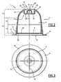
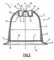
- the capsule 1 according to a first embodiment of the invention, represented on the Figures 1 to 3 , comprises a hollow body 4 and an outlet cap 6 defining together an inner chamber 8 containing a substance (not shown) for the preparation of a beverage.
- the body 4 has a general cup shape and comprises a side wall 10, a bottom 12 closing a closed rear end 20 of the body 4, and an annular flange 16 surrounding an open front end 22 of the body 4.
- the body 4 is made in one piece.
- the side wall 10, the bottom 12 and the annular flange 16 are integral.
- the body 4 is made of an airtight material and water in a plastic material or derived from plastic.
- the side wall 10 extends from the bottom 12 along a longitudinal axis X to the front end 22 of the body 4.
- the side wall 10 includes an inner shoulder 14.
- the shoulder 14 extends in a radial plane and is oriented forward.
- the side wall 10 is substantially frustoconical of revolution about the longitudinal axis X.
- the side wall 10 comprises a rear section 18, relatively flexible, extending from the bottom 12 and a front section 19, relatively rigid, axially extending the rear section 18.
- the front section 19 has an axially increasing thickness, greater than that of the rear section 18.
- the bottom 12 has a peripheral region 23, extending radially inwards from the side wall 10, and a central region 24.
- the peripheral region 23 is rounded. It extends radially inwards and axially towards the rear from the side wall 10, and has a concavity turned towards the inside of the body 4.
- the central region 24 includes an annular rib 26 projecting axially inwardly of the body 4 from the peripheral region 23.
- the annular rib 26 defines an annular trench 28 open to the exterior of the body 4 rearwardly.
- the annular rib 26 defines a hollow central stud 30 protruding axially from the bottom of the annular trench 28 by defining a recess within the body 4.
- the central region 24 has at least one zone of weakness 32 designed to break under the effect of a fluid under pressure.
- the zones of least resistance 32 are provided, for example, in the form of zones of lesser thickness in the central region 24, defined for example by indentations formed in the central region 24.
- Areas of least resistance 32 are provided in walls of the annular rib 26 and / or on the central stud 30.
- the annular rib 26 comprises an outer tubular portion 36 extending axially inwardly from the peripheral region 23, an inner tubular portion 34 delimiting a lateral face of the central stud 30 and a bottom portion. 38 extending radially between the outer portion 36 and the inner portion 34 imparting to the annular rib 26 a cross section substantially shaped "U".
- zones of least resistance 32 are provided in the bottom portion 38 and in the central stud 30 in the form of areas of lesser thickness.
- the central region 24 is devoid of zone of least resistance 32 in the central block 30.
- the annular rib 26 has areas of lower resistance 32 in the outer portion 36 and / or the inner portion 34 .
- the outer portion 36 and the inner portion 34 converge conferring on the annular rib 26 a cross section substantially shaped "V".
- areas of least resistance 32 may be provided in the outer portion 36, the inner portion 34 and / or the central pin 30.
- the annular trench 28 has an outer edge 44 angular, preferably beveled, at the junction between the annular rib 26 and the peripheral region 23.
- the outer edge 44 defines the rear end 20 of the capsule 1.
- the central stud 30 is axially recessed towards the interior of the body 4 with respect to the outer edge 44.
- the peripheral region 23 has an extra thickness along the outer edge 44, so as to strengthen the outer edge 44.
- the peripheral region 23 has for example an increasing thickness from the side wall 10 to the outer edge 44.
- the internal shoulder 14 is annular and protrudes radially from the side wall 10 towards the inside of the body 4. It is recessed axially towards the inside of the body 4 with respect to the front end 22 of the body 4 and at the edge ring 16.
- the cover 6 is fixed by its periphery to the internal shoulder 14 so that the cover 6 is disposed axially inwards towards the inside of the body 4 with respect to the front end 22 of the body 4.
- the distance of withdrawal of the cover 6 relative to the front end 22 of the body 4 is greater than 1 mm.
- the lid 6 closes the front end 22 of the body 4.
- the lid 6 comprises an outlet filter 49 capable of passing a fluid under pressure while retaining the substance contained in the chamber 8.
- the filter 49 is made of porous filter paper, woven plastic material or perforated plastic film.
- the lid 6 further comprises an air and water-tight membrane 50 doubling the filter 49.
- the membrane 50 has lines of weakness 52, so that the membrane 50 is able to tear under the sole the effect of the pressure of a liquid.
- lines of weakness 52 form a cross. Alternatively, they form a circle, circular arcs, or any other form adapted to allow optimal tearing of the membrane 50.
- the filter 49 is disposed between the chamber 8 and the membrane 50.
- the filter 49 and the membrane 50 are contiguous to each other.
- the filter 49 and the membrane 50 are for example in the form of a bilayer complex film.
- the annular flange 16 extends radially outwardly from the side wall 10.
- the annular flange 16 defines the front end 22 of the body 4.
- the flange 16 has a free marginal region 54. It does not support an attached sealing element or deformable sealing relief. As shown on the Figures 1 to 3 the annular flange 16 is substantially planar.
- the capsule 1 is intended to be disposed in an extraction device 350, represented on the Figures 4 and 5 .
- the extraction device 350 comprises a hollow receiving element 352, defining a housing 353 for receiving the capsule 1, and a support 354. It is adapted to be operated between an open configuration in which the receiving element 352 and the 354 are mutually spaced apart to introduce the capsule 1 into the receiving member 352, and a closed position, shown in FIG. Figure 5 in which the receiving member 352 and the holder 354 are mutually brought together to inject the extraction liquid into the capsule 1.
- the device 350 is shown in an intermediate configuration in which it is partially open, but not yet sufficiently open to allow the introduction of the capsule 1.
- the housing 353 has an inner side face 360, a housing bottom 370 and a conduit 372 for supplying extraction liquid opening on the housing bottom 370, substantially in the center and an opening 316 for introducing the capsule 1.
- the inner side face 360 is of revolution about a longitudinal axis Y. In the example shown, it is substantially frustoconical.
- the longitudinal axes X of the capsule 1 and Y of the housing 353 merge substantially.
- the receiving member 352 has an annular edge 380 surrounding the opening 316.
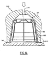
- the capsule 1 has a sufficient axial length so that, in the closed configuration of the extraction device 350, the capsule 1 is supported by its annular rim 16 against the support 354 and by its bottom 12 against the housing bottom 370 along a line closed annular contact contact 122, preferably defined on the peripheral region 23 along the outer edge 44 of the annular trench 28.
- the capsule 1 is advantageously adapted to deform elastically under the effect of an axial compression force F to ensure sufficient contact between the bottom 12 and the housing bottom 370.
- the capsule 1 is adapted so that, under the effect of the axial compression force F, at least one annular zone 130 of the bottom 12 and / or the side wall 10 of the capsule 1 expands radially outwardly so as to ensure an additional contact 128 with the lateral face 360 of the housing 353, following a closed annular contact line.
- the capsule 1 is first placed in the device 350 in open configuration, then the device 350 is operated to move in closed configuration.
- the capsule 1 is supported by its annular flange 16 against the support 354 and the receiving element 352 bears axially on the bottom 12 of the capsule 1, so that the contact 122 is created , and the body 4 is deformed as a whole so that the contact 128 is created with the receiving element 352 of the device 350.
- the extraction fluid is injected under pressure through the conduit 372.
- the zones of weakness 32 of the central region 24 of the bottom 12 rupture and the extraction fluid enters the capsule 1.
- the bottom reinforced by an annular rib enables the body of the capsule to be made of a relatively flexible, deformable material, without the bottom collapsing towards the inside of the capsule under the effect of the fluid pressure.
- the convexity of the bottom makes it possible to define a resilient and elastically deformable bottom, with a volume of the large chamber making it possible to load a larger quantity of substance into the capsule.
- the rib delimiting in the outer face an annular trench makes it possible to improve the injection of the extraction liquid into the capsule.
- the presence of an annular rim makes it possible to increase the stability of the capsule on the support of the extraction device.
- the capsule has a cup-shaped body whose bottom is airtight and watertight, the body being closed by a seal that is airtight and watertight.
- the tightness of the capsule keeps the substance safe from air and moisture.
- the cover has a membrane tearing under the effect of the pressurized fluid allowing appropriate opening of the cap from a determined pressure level, with a beneficial delay effect for a quality extraction.
- the operculum recessed axially towards the inside of the body avoids any interference with the support of the extraction device before the opening of the membrane, and thus allows controlled opening of the capsule.
- the membrane associated with a filter ensures extraction of the substance under satisfactory pressure conditions with effective retention of the substance inside the capsule.
- the operculum provided in the form of a complex film facilitates the manufacture of the capsule at low cost.
- the capsule variants illustrated on the figures 6 and 7 differ from that of Figures 1 to 3 in that the marginal region 54 of the annular flange 16 is inclined towards the front of the capsule 1. As shown in FIG. Figure 6 the annular flange 16 is curved towards the front of the capsule 1. As shown in FIG. Figure 7 , the annular flange 16 is frustoconical flaring forward.
- Such a flange 16 makes it possible to guarantee and reinforce the contact 122 between the bottom 12 of the capsule 1 and the housing bottom 370 when the device 350 is closed, while being able to deform to allow the closure of the extraction device 350.
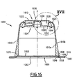
- the capsule 1000 according to a second embodiment of the invention, represented on the Figures 9 to 21 , includes, as visible on the Figures 9 and 10 , a hollow body 1004 and an outlet cap 1006 together defining an inner chamber 1008 containing a substance (not shown) for the preparation of a beverage.
- the body 1004 has a general cup shape and is airtight and watertight. It comprises an outer side wall 1010, a bottom 1012 closing a rear end 1020 of the body 1004, and an annular flange 1016 surrounding an open front end 1022 of the body 1004.
- the outer side wall 1010 and the bottom 1012 are made of material and are made of a first plastic material airtight and watertight.
- the first plastic material is chosen to be inert with respect to the substance contained in the capsule 1000.
- said first material is translucent and is not colored in the mass, so as to avoid the diffusion of the coloring. in the substance.
- the second plastic material is polyamide. Polyamide does not interfere with food products and is a very effective barrier to air and water.
- the annular flange 1016 is made of a second plastic material, different from the first plastic material.
- the second plastic material is preferably chosen to be a low cost material. Since it is not in contact with the substance, its properties vis-à-vis the substance do not take into account in the choice of the second material.
- the second plastic material is polyurethane, which is an inexpensive material.
- the first and second plastic materials are compatible materials, i.e. materials adapted to polymerize with each other.
- the second material is colored in the mass.
- the annular flanges 1016 of 1000 capsules containing different substances so as to easily distinguish a 1000 capsule containing a first substance of another 1000 capsule containing a second substance, different from the first.
- the outer side wall 1010 extends from the bottom 1012 along a longitudinal axis X to the front end 1022 of the body 1004.
- the outer side wall 1010 is substantially frustoconical of revolution about the longitudinal axis X. It is rigid. It has an inner surface 1010a, facing the chamber 1008, and an outer surface 1010b, opposite the inner surface 1010a.
- the bottom 1012 comprises a peripheral region 1023 and a central region 1024.
- Peripheral region 1023 is rigid. It is rounded and extends radially inwardly and axially rearwardly from the outer sidewall 1010, and has a concavity facing the interior of the body 1004. It thus extends from the outer sidewall 1010 to the rear end 1020 of the body 1004.
- the rear end 1020 is typically a closed line, for example a circle.
- Central region 1024 enters axially inward of chamber 1008 from the peripheral region.
- the central region 1024 thus defines in the bottom 1012 a recess 1028 outside the body 1004.
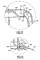
- the central region 1024 comprises an outer tubular portion 1036 extending axially inwardly of the chamber 1008 from the peripheral region 1023, a bottom portion 1038 extending radially inwardly from the inner end. of the outer potion 1036 and closing the recess 1028, and a central inner portion 1034 projecting outwardly from the bottom portion 1038.
- the inner portion 1034 defines a hollow central stud 1030 in the recess 1028.
- the latter thus has an annular shape.
- the outer portion 1036, the bottom portion 1038 and the inner portion 1034 define an annular rib 1026 in the central region 1024.
- the bottom portion 1038 comprises at least one zone 1032 of least resistance provided to break under the effect of a fluid under pressure.
- the or each zone of least resistance is provided to break at a pressure of the fluid under pressure of between 1 and 3 bar.
- the or each zone of least resistance 1032 is provided, for example, in the form of zones of lesser thickness, as shown in FIG. Figure 12 . As long as the or each zone of weakness 1032 is not broken, the bottom 1012, and by extension the entire body 1004, is impermeable to air and liquids.
- the zone of least resistance is defined at the periphery of the bottom portion 1038, at the junction between the bottom portion 1038 and the outer portion 1036.
- the zone of least resistance is in the form of a circular arc.
- the arc of the circle preferably extends over at least 270 °.
- the shape of the inner portion 1034 conditions the axial shear force generated by a pressurized liquid present in the recess 1028.
- the inner portion 1034 has a frustoconical shape, widening from the back to the front of the capsule 1000, and protruding outwardly.
- the inner portion 1034 extends in a radial plane. At a determined pressure of the fluid present in the recess 1028, a flat inner portion 1034 induces a higher shear force than an inner portion protruding outwardly.
- the body 1004 also comprises longitudinal ribs 1042 for stiffening the outer side wall 1010 and radial ribs 1044 for stiffening the bottom 1012.
- Each longitudinal rib 1042 extends longitudinally along the outer sidewall 1010, preferably, as shown, along the inner surface 1010a.
- the longitudinal ribs are adapted to promote the emulsion between the pressurized fluid and the substance contained in the chamber 1008.
- each longitudinal rib 1042 extends along the outer surface 1010b.
- Each radial rib 1044 extends radially between the outer portion 1036 and the peripheral region 1023.
- the radial ribs 1044 stiffen the bottom 12 and thus promote the generation of shear forces induced by the pressure of the fluid under directly on the or each zone of weakness 1032.
- each radial rib 1044 extends in the extension of a longitudinal rib 1042.
- the annular flange 1016 extends radially outwardly from an inner annular rim 1046 to an outer annular rim 1048 from the outer surface 1010b of the outer sidewall 1010. It defines the leading end 1022 of the body 1004. It does not support an attached sealing element or deformable sealing relief. Preferably, it is substantially plane.
- the outer annular border 1048 is free.
- the outer surface 1010b of the outer side wall 1010 defines, near the front end 1022 of the body 1004, an annular clearance 1049 defining a shoulder 1050 and a groove 1052 connecting the annular flange 1016 to the outer side wall 1010.
- the shoulder 1050 is recessed rearwardly relative to the front end 1022. It extends radially and parallel to the front end 1022, between an inner end 1054 and an outer end 1056.
- the groove 1052 is formed in the shoulder 1050 and protrudes longitudinally rearwardly from the inner end 1054 of the shoulder 1050.
- the annular flange 1016 comprises an annular protuberance 1058 protruding longitudinally from the inner annular rim 1046 in the groove 1052.
- the protuberance 1058 cooperates with the groove 1052 to strengthen the connection of the annular flange 1016 to the outer side wall 1010.
- a portion of the outer side wall 1010 extends between the annular flange 1016 and the chamber 1008, which prevents the substance from being in contact with the second material.
- the lid 1006 is fixed by its periphery to the outer side wall 1010 and the annular flange 1016. The lid 1006 thus closes the front end 1022 of the body 1004.
- the lid 1006 comprises an output filter 1060 adapted to let a fluid under pressure by retaining the substance contained in the chamber 1008.
- the filter 1060 is porous filter paper, woven plastic material or perforated plastic film.
- the filter 1060 is, as shown, set back from the front end 1022, to the chamber 1008, and is fixed on its periphery to the inner surface 1010a of the outer side wall 1010.
- the filter 1060 is for example disposed between 1 and 1.5 mm recessed from the front end 1022.
- the lid 1006 further comprises an airtight and water-tight membrane 1062 doubling the filter 1060.
- the membrane 1062 is fixed, for example welded, to the annular flange 1016.
- the membrane 1062 extends along the front end 1022 of the body 1004. The membrane 1062 makes it possible to preserve the substance in an inert atmosphere, so as to avoid any oxidation of the substance.
- the membrane 1062 is peelable, that is to say it can be easily detached from the body 1004.
- it comprises a tongue 1064 extending radially outwardly from the annular flange 1016, to allow a user to easily remove the membrane 1062 before use of the capsule 1000 in an extraction device.
- the membrane 1062 has lines of weakness (not shown), so that the membrane 1062 is able to tear under the sole effect of the pressure of a liquid.
- the extraction can still be performed normally, without risk of damage to the extraction device .
- the filter 1060 is disposed between the chamber 1008 and the membrane 1062.
- the gap between the filter 1060 and the membrane 1062 is preferably filled with an inert gas, typically with nitrogen.
- the capsule 1000 is represented on the Figure 14 inserted into an 1100 beverage extraction device.
- This device 1100 is similar to the extraction device 350 described above. Similar elements are designated by the same reference signs.
- the capsule 1000 is adapted so that the annular edge 380 comes into contact with the annular flange 1016 when the extraction device 1100 is in closed configuration.
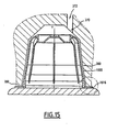
- a variant of the extraction device 1100 is represented on the Figure 15 .
- the conduit 372 for supplying extraction liquid is offset radially with respect to the longitudinal axis Y.
- the capsule 1000 is also adapted for use in drink extraction devices where the arrival of liquid under pressure in the receiving housing 353 is not in the center of the housing 353.
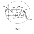
- a variant of the 1000 capsule is presented on Figures 16 and 17 .
- the internal portion 1034 has a hemispherical shape concavity oriented towards the inside of the body 1004. This shape is adapted to allow the rupture of the zone of weakness 1032 at higher pressures in the case where the inner portion 1034 has a frustoconical shape.
- the annular flange 1016 is not bonded to the outer surface 1010b of the outer side wall 1010, but to a front annular face 1066 of the outer side wall 1010. Said front annular face 1066 defines a groove 1068 protruding longitudinally toward the outside. rear and with which cooperates the protuberance 1058 of the annular flange 1016 to strengthen the connection of the annular flange 1016 with the outer side wall 1010.
- the inner surface 1010a of the outer side wall 1010 defines an annular inner shoulder 1070 extending in a radial plane and facing forward.
- the inner shoulder 1070 is recessed axially inwardly of the body 1004 with respect to the front end 1022 of the body 1004 and the annular flange 1016. This inner shoulder 1070 is adapted to support the lid 1006.
- the inner shoulder 1070 is set back relative to the front annular face 1066, the substance is thus not in contact with the second material forming the annular flange 1016.
- the lid 1006 is constituted by a bilayer complex film comprising the filter 1060 and the membrane 1062.
- This complex film is fixed by its periphery on the internal shoulder 1070 so that the lid 1006 is disposed axially inwardly of the body 1004 with respect to the front end 1022 of the body 1004.
- the retraction distance of the lid 1006 from the front end 1022 of the body 1004 is greater than at 1 mm.
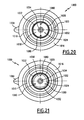
- the bottom portion 1038 comprises a plurality of zones of least resistance 1032, each being formed by two lines of weakness intersecting so as to form a cross.
- the zones of least resistance 1032 are four in number. Alternatively, the number of zones of least resistance 1032 is different.
- the bottom portion 1038 comprises a plurality of zones of least resistance 1032, each being formed by a closed circular line of weakness, each delimiting a disk not including the inner portion 1034.
- the areas of less resistance 1032 are three in number. Alternatively, the number of zones of least resistance 1032 is different.
- the bottom portion 1038 comprises two zones of least resistance 1032, each having the shape of a serrated semicircle and extending at the periphery of the bottom portion 1038, along the junction with the outer portion 1036.
- the bottom 12 further comprises two reinforcing ribs 1080 of the central region 1024.
- Each rib 1080 extends longitudinally between the tubular portion 1026 and the peripheral rim 1030.
- Each rib 1080 is interposed between the two zones 1034 of the least resistance. the example shown, the ribs 1080 are thus diametrically opposed to one another.
- These ribs 1080 are intended to concentrate the shear forces due to the force exerted by the pressurized fluid on the bottom 1012 in the extraction device 1100 on the zones of least resistance 1034.
- the bottom portion 1038 comprises three zones of least resistance 1032, each being constituted by a closed line delimiting a crescent whose long side extends along the outer portion 1036.
- the bottom 1012 also comprises reinforcing ribs 1080 of the central region 1024. These ribs 1080 are here three in number and each is interposed between two zones of weakness 1032.
- the bottom portion 1038 comprises a single zone of weakness 1032 consisting of a closed circular line extending along the outer portion 1036.
- the first plastic material is poured, for example injected, into a mold, to form the bottom 1012 and the outer side wall 1010. Then, in a second step, the second plastic material is in turn poured into the mold. mold, so as to form the annular flange 1016.
- the first and second plastic materials being compatible materials, they bind chemically. In particular, a part of the molecules of the first material diffuses into the second material and vice versa. Thus, a thin layer is formed in which the two materials are mixed and the two materials are thus intimately bonded to each other.
- the body part of the capsule in contact with the substance is formed in a material which is inert with respect to the substance, which makes it possible to preserve the substance under optimal conditions, without the risk of degradation of the substance.
- the substance by oxidation or by toxic elements contained in the material in contact with the substance.
- the fact that the first plastic material is not colored in the mass makes it possible to reduce the probability of migration of toxic elements from the capsule to the substance.
- the fact of using a second material for the annular rim makes it possible to reduce the manufacturing cost of the capsule and also makes it possible, by coloring the second material, to easily identify the substance contained in the chamber of the capsule, without risk of migration of the pigments into the substance, the latter not being in contact with the second material.
Landscapes
- Engineering & Computer Science (AREA)
- Mechanical Engineering (AREA)
- Food Science & Technology (AREA)
- Apparatus For Making Beverages (AREA)
- Closures For Containers (AREA)
- Packages (AREA)
Claims (18)
- Kapsel (1, 1000) zur Extraktion eines Getränks unter Druck, die einen kuppelförmigen Körper (4, 1004) und einen Deckel (6, 1006) umfasst, die gemeinsam eine Kammer (8, 1008) begrenzen, die eine Substanz zur Zubereitung eines Getränks enthält, wobei der Körper (4, 1004) eine etwa kegelstumpfförmige äußere Seitenwand (10, 1010) und einen in einem Stück mit der äußeren Seitenwand (10, 1010) gefertigten Boden (12, 1012) umfasst, der die äußere Seitenwand (10, 1010) an einem hinteren Ende (20, 1020) des Körpers (4, 1004) verschließt, wobei der Deckel (6, 1006) die äußere Seitenwand (10, 1010) am vorderen Ende (22, 1022) des Körpers (4, 1004) verschließt, wobei die Kapsel (1, 1000) dazu geeignet ist, um derart in einer Extraktionsvorrichtung (350, 1100) angeordnet zu sein, dass eine Extraktionsflüssigkeit unter Druck in die Kapsel (1, 1000) durch den Boden (12, 1012) eindringt und diese durch den Deckel (6, 1006) verlässt, wobei der Boden (12, 1012) von einer Umfangsregion (23, 1023) gebildet wird, die ein hinteres Ende (20, 1020) des Körpers (4, 1004) begrenzt, und von einer zentralen Region (24, 1024), die im Verhältnis zum hinteren Ende (20, 1020) in das Innere der Kapsel (1, 1001) hineinragt und eine Aussparung (28, 1028) außerhalb des Körpers (4, 1004) definiert, dadurch gekennzeichnet, dass die zentrale Region (24, 1024) mindestens eine Zone geringerer Festigkeit (32, 1032) umfasst, die vorgesehen ist, unter dem Druck einer Flüssigkeit unter Druck zumindest teilweise zu brechen, und dass der Körper (4, 1004) aus einem Kunststoffmaterial oder einem Kunststoffderivat ist.
- Kapsel (1, 1000) nach Anspruch 1, dadurch gekennzeichnet, dass die zentrale Region (24, 1024) einen Bodenabschnitt (38, 1038) und einen zentralen Höcker (30, 1030) umfasst, der aus dem Bodenabschnitt (38, 1038) nach außen hervorsteht.
- Kapsel (1, 1000) nach Anspruch 2, dadurch gekennzeichnet, dass die zentrale Region (24, 1024) eine ringförmige Rippe (12, 1012) umfasst, die in den Körper (4, 1004) hineinragt, wobei die Aussparung (28, 1028) die Form eines ringförmigen Einschnitts außerhalb des Körpers (4, 1004) aufweist.
- Kapsel (1, 1000) nach Anspruch 1, dadurch gekennzeichnet, dass die zentrale Region (24, 1024) einen flachen Bodenabschnitt (38, 1038) umfasst, der die Aussparung (28, 1028) axial verschließt.
- Kapsel (1, 1000) nach einem der Ansprüche 2 bis 4, wobei die oder jede Region geringerer Festigkeit (32, 1032) im Bodenabschnitt (38, 1038) ausgebildet ist.
- Kapsel (1, 1000) nach Anspruch 5, dadurch gekennzeichnet, dass die zentrale Region (24, 1024) einen rohrförmigen externen Abschnitt (36, 1036) umfasst, der sich ab der Umfangsregion (23, 1023) axial nach in das Innere der Kammer (8, 1008) erstreckt, wobei die oder jede Zone geringerer Festigkeit (32, 1032) an der Verbindung zwischen dem Bodenabschnitt (38, 1038) und dem externen Abschnitt (36, 1036) gebildet ist.
- Kapsel (1, 1000) nach einem der vorangehenden Ansprüche, dadurch gekennzeichnet, dass der Boden (12, 1012) mindestens eine Verstärkungsrippe (1080) für die Verstärkung der zentralen Region (24, 1024) umfasst.
- Kapsel (1, 1000) nach einem der vorangehenden Ansprüche, dadurch gekennzeichnet, dass der Körper (4, 1004) mindestens eine radiale Versteifungsrippe (1044) für die Versteifung der Umfangsregion (23, 1023) umfasst.
- Kapsel (1, 1000) nach einem der vorangehenden Ansprüche, dadurch gekennzeichnet, dass der Boden (12, 1012) und die äußere Seitenwand (10, 1010) des Körpers (4, 1004) vor dem Brechen der oder jeder Zone geringerer Festigkeit (32, 1032) undurchlässig für Luft und Flüssigkeiten sind.
- Kapsel (1, 1000) nach Anspruch 2 oder 3, dadurch gekennzeichnet, dass der zentrale Höcker (30, 1040) eine kegelstumpfförmige Form hat.
- Kapsel (1, 1000) nach Anspruch 2 oder 3, dadurch gekennzeichnet, dass der zentrale Höcker (30, 1040) eine halbkugelförmige Form hat.
- Kapsel (1, 1000) nach einem der vorangehenden Ansprüche, dadurch gekennzeichnet, dass der Deckel (6, 1006) einen Filter (49, 1060) und eine Membran (50, 1062) umfasst.
- Kapsel (1, 1000) nach Anspruch 12, dadurch gekennzeichnet, dass der Filter (49, 1060) zurückgezogen vom vorderen Ende (22, 1022) des Körpers (4, 1004) in Richtung der Kammer (8, 1008) angeordnet ist, wobei sich die Membran (50, 1062) entlang des vorderen Endes (22, 1022) erstreckt.
- Kapsel (1, 1000) nach Anspruch 13, dadurch gekennzeichnet, dass der Raum zwischen dem Filter (49, 1060) und der Membran (50, 1062) mit Stickstoff gefüllt ist.
- Kapsel (1, 1000) nach einem der Ansprüche 12 bis 14, dadurch gekennzeichnet, dass die Membran (50, 1062) abziehbar ist.
- Kapsel (1, 1000) nach einem der vorangehenden Ansprüche, dadurch gekennzeichnet, dass die äußere Seitenwand (10, 1010) und der Boden (12, 1012) aus einem ersten Kunststoff gebildet sind und dass der Körper (4, 1004) einen ringförmigen Rand (16, 1016) umfasst, der sich von der äußeren Seitenwand (10, 1010) radial nach außen erstreckt und das vordere Ende (22, 1022) des Körpers (4, 1004) begrenzt, wobei der ringförmige Rand (16, 1016) von einem zweiten Kunststoff gebildet ist, der sich von dem ersten Kunststoff unterscheidet.
- Kapsel (1, 1000) nach einem der vorangehenden Ansprüche, dadurch gekennzeichnet, dass die oder jede Zone geringerer Festigkeit (32, 1032) geeignet ist, unter dem Druck einer Flüssigkeit unter Druck zwischen 1 und 3 bar inklusive zu brechen.
- System, das eine Kapsel (1, 1000) nach einem der vorangehenden Ansprüche und eine Extraktionsvorrichtung (350, 1100) umfasst, die eine Aufnahme (353), die zur Aufnahme der Kapsel (1, 1000) bestimmt ist, eine Unterlage (354) und eine Zuführungsleitung (372) für die Zuführung einer Extraktionsflüssigkeit unter Druck aufweist.
Priority Applications (21)
| Application Number | Priority Date | Filing Date | Title |
|---|---|---|---|
| PL10306436T PL2394932T3 (pl) | 2010-06-11 | 2010-12-16 | Kapsułka z osłabioną strefą zerwania |
| PCT/FR2011/051320 WO2011154665A1 (fr) | 2010-06-11 | 2011-06-09 | Capsule a zone d'amorce de rupture |
| JP2013543849A JP2014501583A (ja) | 2010-06-11 | 2011-06-09 | 二素材カプセル |
| CN2011800663911A CN103458749A (zh) | 2010-06-11 | 2011-06-09 | 两种材料的囊状件 |
| CA2824135A CA2824135A1 (fr) | 2010-06-11 | 2011-06-09 | Capsule bimatieres |
| CA2802166A CA2802166A1 (fr) | 2010-06-11 | 2011-06-09 | Capsule a zone d'amorce de rupture |
| JP2013513738A JP2013530750A (ja) | 2010-06-11 | 2011-06-09 | 破裂開始領域を有するカプセル |
| RU2013100977/12A RU2569281C2 (ru) | 2010-06-11 | 2011-06-09 | Капсула с зоной начала разрыва |
| US13/703,583 US20130087051A1 (en) | 2010-06-11 | 2011-06-09 | Capsule having a rupture initiation area |
| CN201180039592.2A CN103079436B (zh) | 2010-06-11 | 2011-06-09 | 具有破裂开启区域的容器 |
| BR112013015161A BR112013015161A2 (pt) | 2010-12-16 | 2011-06-09 | cápsula para extração de uma bebida sob pressão e sistema |
| PCT/FR2011/051321 WO2011154666A1 (fr) | 2010-06-11 | 2011-06-09 | Capsule bimatières |
| US13/994,658 US20140069280A1 (en) | 2010-06-11 | 2011-06-09 | Two-material capsule |
| RU2013132755/12A RU2602052C2 (ru) | 2010-12-16 | 2011-06-09 | Капсула из двух материалов |
| CA2837812A CA2837812A1 (fr) | 2010-06-11 | 2011-06-14 | Capsule pour l'extraction d'une boisson sous pression |
| ES11735489.4T ES2548903T3 (es) | 2010-06-11 | 2011-06-14 | Cápsula para la extracción de una bebida a presión |
| PCT/FR2011/051343 WO2012010760A1 (fr) | 2010-06-11 | 2011-06-14 | Capsule pour l'extraction d'une boisson sous pression |
| PCT/FR2011/051348 WO2011154672A1 (fr) | 2010-06-11 | 2011-06-14 | Capsule pour l'extraction d'une boisson sous pression |
| EP20110735489 EP2580145B1 (de) | 2010-06-11 | 2011-06-14 | Kapsel zur druckextraktion eines getränks |
| PCT/EP2011/070986 WO2012079959A1 (fr) | 2010-12-16 | 2011-11-24 | Capsule pour l'extraction d'une boisson sous pression a tronconicite variable |
| EP11794072.6A EP2651778B1 (de) | 2010-12-16 | 2011-11-24 | Kapsel mit variabler kegelstumpfform zur extraktion eines getränkes unter druck |
Applications Claiming Priority (3)
| Application Number | Priority Date | Filing Date | Title |
|---|---|---|---|
| FR1054651 | 2010-06-11 | ||
| FR1054652 | 2010-06-11 | ||
| FR1054653 | 2010-06-11 |
Publications (2)
| Publication Number | Publication Date |
|---|---|
| EP2394932A1 EP2394932A1 (de) | 2011-12-14 |
| EP2394932B1 true EP2394932B1 (de) | 2013-06-05 |
Family
ID=43640065
Family Applications (2)
| Application Number | Title | Priority Date | Filing Date |
|---|---|---|---|
| EP10306436.6A Active EP2394932B1 (de) | 2010-06-11 | 2010-12-16 | Kapsel mit Anbruchzone |
| EP10306432.5A Active EP2394539B1 (de) | 2010-06-11 | 2010-12-16 | Bimaterielle Kapsel |
Family Applications After (1)
| Application Number | Title | Priority Date | Filing Date |
|---|---|---|---|
| EP10306432.5A Active EP2394539B1 (de) | 2010-06-11 | 2010-12-16 | Bimaterielle Kapsel |
Country Status (9)
| Country | Link |
|---|---|
| US (2) | US20130087051A1 (de) |
| EP (2) | EP2394932B1 (de) |
| JP (2) | JP2013530750A (de) |
| CN (2) | CN103079436B (de) |
| CA (2) | CA2824135A1 (de) |
| ES (2) | ES2426266T3 (de) |
| PL (2) | PL2394539T3 (de) |
| RU (1) | RU2569281C2 (de) |
| WO (2) | WO2011154666A1 (de) |
Cited By (6)
| Publication number | Priority date | Publication date | Assignee | Title |
|---|---|---|---|---|
| WO2018124901A1 (pt) | 2016-12-29 | 2018-07-05 | Novadelta - Comércio E Indústria De Cafés, S.A. | Cápsula com retenção de vedação e sistema de preparação de produtos edíveis com base em cápsulas |
| WO2018124899A1 (pt) | 2016-12-29 | 2018-07-05 | Novadelta - Comércio E Indústria De Cafés, S.A. | Cápsula com uma passagem proporcionada como um recesso e sistema de preparação de produtos edíveis |
| WO2018124898A1 (pt) | 2016-12-29 | 2018-07-05 | Novadelta - Comércio E Indústria De Cafés, S.A. | Cápsula com via de passagem em recesso e sistema de preparação de produtos edíveis |
| WO2018124902A1 (pt) | 2016-12-29 | 2018-07-05 | Novadelta - Comércio E Indústria De Cafés, S.A. | Cápsula com vedação amelhorada |
| WO2018124900A1 (pt) | 2016-12-29 | 2018-07-05 | Novadelta - Comércio E Indústria De Cafés, S.A. | Cápsula com uma via de passagem proporcionada como um recesso e sistema de preparação de produtos edíveis |
| US10881582B2 (en) | 2018-06-11 | 2021-01-05 | Glaxosmithkline Consumer Healthcare Holdings (Us) Llc | Individual dose pack |
Families Citing this family (57)
| Publication number | Priority date | Publication date | Assignee | Title |
|---|---|---|---|---|
| US10722066B2 (en) * | 2010-12-04 | 2020-07-28 | Adrian Rivera | Windowed single serving brewing material holder |
| US11832755B2 (en) * | 2007-07-13 | 2023-12-05 | Adrian Rivera | Brewing material container for a beverage brewer |
| CN102015488B (zh) * | 2008-04-30 | 2013-09-11 | 雀巢产品技术援助有限公司 | 容纳有饮料配料并具有进口侧隔膜的密封胶囊 |
| EP3521210B1 (de) * | 2010-07-22 | 2020-01-08 | K-fee System GmbH | Portionskapsel mit barcode |
| EP2420374A1 (de) * | 2010-08-20 | 2012-02-22 | Nestec S.A. | Spritzgussetikettierter Behälter |
| ES2573304T5 (es) * | 2011-12-21 | 2022-03-02 | Delica Ag | Cápsula, cuerpo de la cápsula, método y sistema para preparar una bebida |
| US9737166B2 (en) | 2012-04-11 | 2017-08-22 | Koninklijke Philips N.V. | Beverage producing system and capsule |
| CN104379006B (zh) * | 2012-05-15 | 2017-10-20 | 日本烟草产业株式会社 | 收纳有液体的胶囊及具备该胶囊的吸烟物品 |
| ITRE20120081A1 (it) * | 2012-11-12 | 2014-05-13 | T M E S R L | Capsula per la preparazione di bevande |
| US9221204B2 (en) * | 2013-03-14 | 2015-12-29 | Kortec, Inc. | Techniques to mold parts with injection-formed aperture in gate area |
| PT106850A (pt) * | 2013-03-25 | 2014-09-25 | Galv O E Noronha Lda | Sistema de rotura aplicado em cápsulas para máquinas de café expresso, chá ou outros solúveis, fabricadas em material termo plástico, alumínio ou materiais similares |
| ES2423832B2 (es) * | 2013-05-17 | 2014-05-19 | Unión Tostadora, S.A. | Estructura de cápsula de preparación de bebida |
| EP4190211A1 (de) | 2013-05-17 | 2023-06-07 | Koninklijke Douwe Egberts B.V. | Getränkezubereitungssystem, kapsel und verfahren zur herstellung eines getränks |
| GB201308927D0 (en) | 2013-05-17 | 2013-07-03 | Kraft Foods R & D Inc | A beverage preparation system, a capsule and a method for forming a beverage |
| PT107051B (pt) * | 2013-07-09 | 2020-07-13 | Novadelta - Comércio E Indústria De Cafés, Lda | Embalagem de porção e sistema de preparação de bebidas compreendendo diferentes tipos da referida embalagem de porção |
| US9902556B2 (en) * | 2013-07-10 | 2018-02-27 | Nestec S.A. | Capsule for beverage preparation |
| USD742221S1 (en) * | 2013-08-13 | 2015-11-03 | Caffitaly System S.P.A. | Capsule for making beverages |
| USD732390S1 (en) * | 2013-08-15 | 2015-06-23 | 2266170 Ontario Inc. | Capsule |
| USD731884S1 (en) * | 2013-08-15 | 2015-06-16 | 2266170 Ontario Inc. | Capsule |
| USD731890S1 (en) * | 2013-08-15 | 2015-06-16 | 2266170 Ontario Inc. | Capsule |
| GB2545569B (en) * | 2013-10-16 | 2018-08-29 | Leslie Gort Barten | Coffee capsule |
| CN103565281A (zh) * | 2013-11-22 | 2014-02-12 | 傅杰 | 一种充氮气保鲜的咖啡胶囊 |
| JP6343007B2 (ja) * | 2013-12-18 | 2018-06-13 | トゥットエスプレッソ エス.アール.エル. | 飲料供給用のカプセル及びシステム |
| FR3018270B1 (fr) * | 2014-03-05 | 2016-04-15 | Brain Corp S A | Capsule pour la preparation d'une boisson |
| LU92411B1 (fr) * | 2014-03-24 | 2015-09-25 | Brain Corp Sa | Capsule pour la préparation d'une boisson |
| CH709597A2 (de) * | 2014-05-06 | 2015-11-13 | Delica Ag | Kapsel für Getränkzubereitung. |
| LU92497B1 (fr) * | 2014-07-10 | 2016-01-11 | Brain Corp Sa | Capsule non pré-percée pour la préparation d'une boisson |
| GB2528663A (en) * | 2014-07-25 | 2016-02-03 | Koninkl Douwe Egberts Bv | A capsule, a beverage preparation system and a method for forming a beverage |
| GB201420262D0 (en) | 2014-11-14 | 2014-12-31 | Kraft Foods R & D Inc | A method of forming a cup-shaped body for a beverage capsule |
| USD757537S1 (en) | 2014-12-11 | 2016-05-31 | 2266170 Ontario Inc. | Capsule |
| PL3261957T5 (pl) * | 2015-02-27 | 2023-03-13 | K-Fee System Gmbh | Porcjowana kapsuła z wkładem filtrującym, połączonym przez zgrzewanie |
| USD778157S1 (en) | 2015-04-13 | 2017-02-07 | 2266170 Ontario Inc. | Capsule |
| WO2016193842A1 (en) * | 2015-05-29 | 2016-12-08 | Bacon, Brian | Capsules for containing coffee or another substance from which a beverage can be extracted using hot water |
| KR102114206B1 (ko) | 2015-06-10 | 2020-05-25 | 카-페 시스템 게엠베하 | 3-플라이 부직 직물을 가지는 1인분용 캡슐 |
| US20180178972A1 (en) * | 2015-07-01 | 2018-06-28 | Diffussence | Capsule for preparing a beverage, manufacturing method and implementation method |
| RU2018105139A (ru) | 2015-07-13 | 2019-08-13 | К-Фее Зюстем Гмбх | Фильтрующий элемент с вырезом |
| CA2998669C (en) | 2015-09-18 | 2020-01-07 | K-Fee System Gmbh | Adapter for a single serve capsule |
| LU92840B1 (fr) * | 2015-10-02 | 2017-04-03 | Brain Corp S A | Capsule pour la préparation d'une boisson telle que du café ou une infusion |
| ITUB20156879A1 (it) * | 2015-12-07 | 2017-06-07 | Lavazza Luigi Spa | Cartuccia per la preparazione di un prodotto liquido e relativo assortimento |
| EP3181484A1 (de) * | 2015-12-16 | 2017-06-21 | Mühlemann IP GmbH | Kapselbecher einer kaffeekapsel |
| US20170253000A1 (en) * | 2016-03-03 | 2017-09-07 | Juicero, Inc. | Juicer with locking mechanism |
| US20170252994A1 (en) * | 2016-03-03 | 2017-09-07 | Juicero, Inc. | Juicing system with juicer cartridge restraints |
| DE102016116959A1 (de) | 2016-09-09 | 2018-03-15 | Xpressivo Ag | Kapsel mit Bogenform zwischen Kapselwand und Kapselboden |
| IT201700074959A1 (it) * | 2017-07-04 | 2019-01-04 | Pepeimpex Ltd | Capsula per prodotti da infusione |
| US11504898B2 (en) | 2017-10-27 | 2022-11-22 | Kiefel Gmbh | Method of thermoforming a foil, forming tool, thermoforming tool, installation for thermoforming, container and brewing container |
| DE202018106461U1 (de) * | 2017-10-27 | 2018-11-26 | Kiefel Packaging B.V. | Kapselkörper, Brühkapsel und Behälter, Formwerkzeug und Thermoformwerkzeug |
| EP3505022A1 (de) | 2017-12-28 | 2019-07-03 | Koninklijke Philips N.V. | Mischvorrichtung mit einer dichtung |
| IT201800002185A1 (it) * | 2018-01-30 | 2019-07-30 | Goglio Spa | Capsula con valvola di degassazione |
| IT201800010741A1 (it) * | 2018-11-30 | 2020-05-30 | Bisio Progetti Spa | Capsula per la preparazione di bevande ad infusione ad estrazione migliorata |
| CN109431275B (zh) * | 2018-12-10 | 2023-10-27 | 浙江西文智能科技有限公司 | 带背压的饮料胶囊 |
| IT201900005002A1 (it) * | 2019-04-03 | 2020-10-03 | Flo Spa | Capsula per la preparazione di bevande |
| IT201900005014A1 (it) * | 2019-04-03 | 2020-10-03 | Flo Spa | Capsula per la preparazione di bevande |
| CN110037558A (zh) * | 2019-04-30 | 2019-07-23 | 深圳市西啡科技有限公司 | 一种胶囊杯 |
| US11072489B2 (en) * | 2019-08-14 | 2021-07-27 | Pepsico, Inc. | Beverage-ingredient cartridge and cap for beverage-ingredient cartridge |
| US11805934B1 (en) * | 2020-10-21 | 2023-11-07 | Adrian Rivera | Brewing material lid and container for a beverage brewer |
| USD1015064S1 (en) * | 2021-07-28 | 2024-02-20 | K-Fee System Gmbh | Portion capsule |
| USD1013452S1 (en) * | 2021-07-30 | 2024-02-06 | K-Fee System Gmbh | Portion capsule |
Citations (8)
| Publication number | Priority date | Publication date | Assignee | Title |
|---|---|---|---|---|
| FR2211924A5 (de) * | 1972-11-27 | 1974-07-19 | Battelle Memorial Institute | |
| GB2023086A (en) * | 1978-06-05 | 1979-12-28 | Kitahara R | Sealed container for beverage materials |
| WO2005066040A2 (en) * | 2003-12-29 | 2005-07-21 | Ilenaig S.A.S. Di Giannelli Giuseppe E C. | Capsule and method for the preparation of beverages |
| EP1767467A1 (de) * | 2005-09-21 | 2007-03-28 | ILLYCAFFE' S.p.A. | Kapsel enthaltend einer Substanz zum Extrahieren eines Getränks |
| WO2009050540A1 (fr) * | 2007-09-03 | 2009-04-23 | Gaillard, Jean-Paul | Capsule pour la preparation d'une boisson |
| EP2210826A1 (de) * | 2009-01-22 | 2010-07-28 | Nestec S.A. | Kapsel mit integriertem Durchstechelement und Gerät für die Zubereitung eines Getränks |
| EP2284100A1 (de) * | 2009-08-05 | 2011-02-16 | Nestec S.A. | Kapsel mit zugeordneten Dichtungsmitteln |
| EP2287090A1 (de) * | 2009-08-19 | 2011-02-23 | Nestec S.A. | Kapsel zur Herstellung eines Kaffeeextrakts mit einer Struktur zur Erleichterung der Perforation zur Einspritzung von Wasser |
Family Cites Families (32)
| Publication number | Priority date | Publication date | Assignee | Title |
|---|---|---|---|---|
| CH605293A5 (de) | 1976-12-17 | 1978-09-29 | Nestle Sa | |
| JPH0513329U (ja) * | 1991-06-14 | 1993-02-23 | 健五 多川 | コ−ヒ−等の抽出器 |
| JPH1053250A (ja) * | 1996-08-06 | 1998-02-24 | Takeyoshi Kajinaga | 液体注出装置 |
| US20030029876A1 (en) * | 2000-07-17 | 2003-02-13 | Jean-Pierre Giraud | Dual wall insulated cup assembly and a method of manufacturing an insulated cup assembly |
| DE10211327B4 (de) * | 2002-03-14 | 2015-09-24 | Caffitaly System S.P.A. | Portionenkapsel mit einer partikelförmigen mittels Wasser extrahierbaren Substanz zur Herstellung eines Getränks |
| WO2004026091A1 (en) * | 2002-09-20 | 2004-04-01 | Nestec S.A. | Method, device, and capsule for preparing a foamy liquid food |
| GB2397498B (en) * | 2003-01-24 | 2006-01-04 | Kraft Foods R & D Inc | Cartridge and method for the preparation of beverages |
| ES2338640T3 (es) * | 2003-03-24 | 2010-05-11 | Nestec S.A. | Dispositivo para bombear un liquido a partir de un embalaje o de un recipiente. |
| DK1462042T3 (da) * | 2003-03-24 | 2007-06-04 | Nestec Sa | Engangsemballage til fordeling af en væske, der kan pumpes med en venturi-indretning |
| EP1557373A1 (de) * | 2004-01-26 | 2005-07-27 | Tuttoespresso S.p.a. | Verfahren, Vorrichtung und Packung für die Herstellung von Getränken aus löslichen Mischungen |
| BRPI0509166A (pt) * | 2004-03-26 | 2007-09-11 | Illycaffe Spa | cartucho para extrair uma bebida de uma substáncia particulada contida no mesmo por meio de água sob pressão, e, conjunto de extração para ser montado em máquina de extração de bebidas |
| GB0423545D0 (en) * | 2004-10-22 | 2004-11-24 | Kraft Foods R & D Inc | Pod for preparing a beverage |
| DE602004008113T3 (de) * | 2004-10-25 | 2019-03-07 | Nestec S.A. | Getränkezubereitungssystem |
| DE102005016297A1 (de) * | 2005-04-08 | 2006-10-12 | Tchibo Gmbh | Portionskapsel |
| PT2012994E (pt) * | 2006-04-24 | 2012-09-20 | Nestec Sa | Método para produzir uma cápsula para preparar uma bebida com um elemento de vedação para estanquidade a água fixo aquela |
| ES2326909T3 (es) * | 2006-04-24 | 2009-10-21 | Nestec S.A. | Capsula para la preparacion de una bebida con un elemento de cierre hermetico unido a la misma y procedimiento de fabricacion de la misma. |
| EP1944248B1 (de) * | 2007-01-15 | 2017-12-13 | Swiss Caffe Asia Ltd. | Kapsel, Mittel zum Penetrieren des Bodens einer Kapsel und Vorrichtung für die Zubereitung eines Getränks |
| EP1974638A1 (de) * | 2007-03-29 | 2008-10-01 | Tchibo GmbH | System mit einer Getränkemaschine und mit Portionskapseln |
| US8431175B2 (en) * | 2007-06-05 | 2013-04-30 | Nestec S.A. | Method for preparing a beverage or food liquid and system using brewing centrifugal force |
| EP2152607B1 (de) * | 2007-06-05 | 2012-01-11 | Nestec S.A. | Einwegkapsel zur herstellung eines flüssigen nahrungsmittels durch zentrifugierung |
| US8322271B2 (en) * | 2007-07-02 | 2012-12-04 | Brewl Technologies, Inc. | Infusible material capsule for brewing a beverage |
| US20090229472A1 (en) * | 2008-03-12 | 2009-09-17 | Ferrara Jr Daniel A | Brewing system and packaging |
| ATE508074T1 (de) * | 2008-03-12 | 2011-05-15 | Nestec Sa | Kapsel mit flussregulierung und filterelement |
| CA2725362C (en) * | 2008-04-24 | 2017-03-28 | Tconcept Company S.P.R.L. | Capsule, device, and method for preparing infused beverages |
| ES2377030T3 (es) * | 2008-07-15 | 2012-03-21 | Nestec S.A. | Procedimiento para la aplicación de un caucho de junta líquido sobre una cápsula |
| ITBO20080656A1 (it) * | 2008-10-27 | 2010-04-28 | Arnoplast Srl | Capsula per prodotti da infusione |
| KR101648233B1 (ko) * | 2008-12-09 | 2016-08-12 | 네스텍 소시에테아노님 | 음료 준비 장치에서 원심분리에 의해 음료를 준비하기 위한 캡슐 및 상기 캡슐을 이용한 장치 |
| EP2364930B1 (de) * | 2009-03-19 | 2018-12-05 | Nestec S.A. | Kapsel zur Zubereitung von Kaffee in einer Vorrichtung mit einem Kartuschenhalter mit Aussparung und eingelassenen Elementen |
| EP2239212B1 (de) * | 2009-04-09 | 2015-11-11 | Nestec S.A. | Kapsel zur Herstellung eines Getränks mit einer einen Strömungspfad aufweisenden Ausgabewand |
| DK2443046T3 (en) * | 2009-06-17 | 2016-01-04 | Koninkl Douwe Egberts Bv | A capsule for containing beverage ingredients |
| US9085410B2 (en) * | 2010-06-10 | 2015-07-21 | Fres-Co System Usa, Inc. | Single brew beverage cartridge system including same and method of use |
| WO2012144885A1 (en) * | 2011-03-03 | 2012-10-26 | Biserkon Holdings Ltd. | Capsule |
-
2010
- 2010-12-16 PL PL10306432T patent/PL2394539T3/pl unknown
- 2010-12-16 ES ES10306436T patent/ES2426266T3/es active Active
- 2010-12-16 ES ES10306432.5T patent/ES2450140T3/es active Active
- 2010-12-16 EP EP10306436.6A patent/EP2394932B1/de active Active
- 2010-12-16 EP EP10306432.5A patent/EP2394539B1/de active Active
- 2010-12-16 PL PL10306436T patent/PL2394932T3/pl unknown
-
2011
- 2011-06-09 CN CN201180039592.2A patent/CN103079436B/zh not_active Expired - Fee Related
- 2011-06-09 CA CA2824135A patent/CA2824135A1/fr not_active Abandoned
- 2011-06-09 WO PCT/FR2011/051321 patent/WO2011154666A1/fr active Application Filing
- 2011-06-09 CN CN2011800663911A patent/CN103458749A/zh active Pending
- 2011-06-09 CA CA2802166A patent/CA2802166A1/fr not_active Abandoned
- 2011-06-09 RU RU2013100977/12A patent/RU2569281C2/ru not_active IP Right Cessation
- 2011-06-09 WO PCT/FR2011/051320 patent/WO2011154665A1/fr active Application Filing
- 2011-06-09 JP JP2013513738A patent/JP2013530750A/ja active Pending
- 2011-06-09 JP JP2013543849A patent/JP2014501583A/ja not_active Ceased
- 2011-06-09 US US13/703,583 patent/US20130087051A1/en not_active Abandoned
- 2011-06-09 US US13/994,658 patent/US20140069280A1/en not_active Abandoned
Patent Citations (8)
| Publication number | Priority date | Publication date | Assignee | Title |
|---|---|---|---|---|
| FR2211924A5 (de) * | 1972-11-27 | 1974-07-19 | Battelle Memorial Institute | |
| GB2023086A (en) * | 1978-06-05 | 1979-12-28 | Kitahara R | Sealed container for beverage materials |
| WO2005066040A2 (en) * | 2003-12-29 | 2005-07-21 | Ilenaig S.A.S. Di Giannelli Giuseppe E C. | Capsule and method for the preparation of beverages |
| EP1767467A1 (de) * | 2005-09-21 | 2007-03-28 | ILLYCAFFE' S.p.A. | Kapsel enthaltend einer Substanz zum Extrahieren eines Getränks |
| WO2009050540A1 (fr) * | 2007-09-03 | 2009-04-23 | Gaillard, Jean-Paul | Capsule pour la preparation d'une boisson |
| EP2210826A1 (de) * | 2009-01-22 | 2010-07-28 | Nestec S.A. | Kapsel mit integriertem Durchstechelement und Gerät für die Zubereitung eines Getränks |
| EP2284100A1 (de) * | 2009-08-05 | 2011-02-16 | Nestec S.A. | Kapsel mit zugeordneten Dichtungsmitteln |
| EP2287090A1 (de) * | 2009-08-19 | 2011-02-23 | Nestec S.A. | Kapsel zur Herstellung eines Kaffeeextrakts mit einer Struktur zur Erleichterung der Perforation zur Einspritzung von Wasser |
Cited By (6)
| Publication number | Priority date | Publication date | Assignee | Title |
|---|---|---|---|---|
| WO2018124901A1 (pt) | 2016-12-29 | 2018-07-05 | Novadelta - Comércio E Indústria De Cafés, S.A. | Cápsula com retenção de vedação e sistema de preparação de produtos edíveis com base em cápsulas |
| WO2018124899A1 (pt) | 2016-12-29 | 2018-07-05 | Novadelta - Comércio E Indústria De Cafés, S.A. | Cápsula com uma passagem proporcionada como um recesso e sistema de preparação de produtos edíveis |
| WO2018124898A1 (pt) | 2016-12-29 | 2018-07-05 | Novadelta - Comércio E Indústria De Cafés, S.A. | Cápsula com via de passagem em recesso e sistema de preparação de produtos edíveis |
| WO2018124902A1 (pt) | 2016-12-29 | 2018-07-05 | Novadelta - Comércio E Indústria De Cafés, S.A. | Cápsula com vedação amelhorada |
| WO2018124900A1 (pt) | 2016-12-29 | 2018-07-05 | Novadelta - Comércio E Indústria De Cafés, S.A. | Cápsula com uma via de passagem proporcionada como um recesso e sistema de preparação de produtos edíveis |
| US10881582B2 (en) | 2018-06-11 | 2021-01-05 | Glaxosmithkline Consumer Healthcare Holdings (Us) Llc | Individual dose pack |
Also Published As
| Publication number | Publication date |
|---|---|
| ES2450140T3 (es) | 2014-03-24 |
| EP2394539B1 (de) | 2013-12-04 |
| PL2394932T3 (pl) | 2013-10-31 |
| WO2011154666A1 (fr) | 2011-12-15 |
| CA2824135A1 (fr) | 2011-12-15 |
| CA2802166A1 (fr) | 2011-12-15 |
| CN103079436A (zh) | 2013-05-01 |
| JP2013530750A (ja) | 2013-08-01 |
| EP2394932A1 (de) | 2011-12-14 |
| WO2011154665A1 (fr) | 2011-12-15 |
| US20140069280A1 (en) | 2014-03-13 |
| EP2394539A1 (de) | 2011-12-14 |
| US20130087051A1 (en) | 2013-04-11 |
| RU2569281C2 (ru) | 2015-11-20 |
| CN103079436B (zh) | 2016-04-20 |
| JP2014501583A (ja) | 2014-01-23 |
| ES2426266T3 (es) | 2013-10-22 |
| RU2013100977A (ru) | 2014-07-20 |
| PL2394539T3 (pl) | 2014-05-30 |
| CN103458749A (zh) | 2013-12-18 |
Similar Documents
| Publication | Publication Date | Title |
|---|---|---|
| EP2394932B1 (de) | Kapsel mit Anbruchzone | |
| EP2580145B1 (de) | Kapsel zur druckextraktion eines getränks | |
| EP1247756B1 (de) | Geschlossene Kapsel zur Getränkezubereitung | |
| EP1611024B1 (de) | Kapsel mit zerstörbarem deckel, sowie behälterverschluss und behälter mit einer solchen kapsel | |
| WO2012079959A1 (fr) | Capsule pour l'extraction d'une boisson sous pression a tronconicite variable | |
| EP2782848B1 (de) | Kapsel zur druckextraktion eines getränks mit einer durch die unter druck stehende flüssigkeit einzureissenden flüssigkeitseinlasswand | |
| EP1968870A1 (de) | Ring für aerosol-spenderventil | |
| LU93172B1 (fr) | Capsule pour la préparation d'une boisson | |
| EP2021263B1 (de) | Verschlussglied, fluidproduktabgabevorrichtung mit solch einem glied und verfahren zur herstellung solch einer abgabevorrichtung | |
| EP2923969B1 (de) | Kapsel zur herstellung eines getränks | |
| EP2630054B1 (de) | Dichtungselement und fluidproduktspender mit einem solchen element | |
| FR2482567A1 (fr) | Dispositif d'obturation pour conteneur du type souple de matieres fluides | |
| CA3144424A1 (fr) | Capsule pour la preparation d'une boisson | |
| EP2931630A1 (de) | Kapsel zur zubereitung eines getränks | |
| EP2785614B1 (de) | Kapsel zur extraktion eines unter druck stehenden getränks | |
| EP2530031B1 (de) | Kapsel zur Extraktion eines unter Druck stehenden Getränks | |
| WO2014188128A1 (fr) | Obturateur d'un connecteur pour poche de perfusion | |
| EP2530030A1 (de) | Kapsel zur Extraktion eines unter Druck stehenden Getränks | |
| CA2470224A1 (fr) | Embout perfuseur pour poche souple a usage medical | |
| LU92799B1 (fr) | Capsule pour la préparation d'une boisson | |
| FR2907432A1 (fr) | Conditionnement pour deux composants a melanger et bouchon-dose prevu a cet effet | |
| FR2966134A1 (fr) | Conteneur a dose de liquide rapportee | |
| FR2733739A1 (fr) | Bouchon adaptable pour canette |
Legal Events
| Date | Code | Title | Description |
|---|---|---|---|
| 17P | Request for examination filed |
Effective date: 20110614 |
|
| AK | Designated contracting states |
Kind code of ref document: A1 Designated state(s): AL AT BE BG CH CY CZ DE DK EE ES FI FR GB GR HR HU IE IS IT LI LT LU LV MC MK MT NL NO PL PT RO RS SE SI SK SM TR |
|
| AX | Request for extension of the european patent |
Extension state: BA ME |
|
| PUAI | Public reference made under article 153(3) epc to a published international application that has entered the european phase |
Free format text: ORIGINAL CODE: 0009012 |
|
| 17Q | First examination report despatched |
Effective date: 20120117 |
|
| REG | Reference to a national code |
Ref country code: DE Ref legal event code: R079 Ref document number: 602010007568 Country of ref document: DE Free format text: PREVIOUS MAIN CLASS: B65D0085804000 Ipc: B65D0085816000 |
|
| RIC1 | Information provided on ipc code assigned before grant |
Ipc: B65D 85/816 20060101AFI20120716BHEP |
|
| GRAP | Despatch of communication of intention to grant a patent |
Free format text: ORIGINAL CODE: EPIDOSNIGR1 |
|
| GRAP | Despatch of communication of intention to grant a patent |
Free format text: ORIGINAL CODE: EPIDOSNIGR1 |
|
| GRAS | Grant fee paid |
Free format text: ORIGINAL CODE: EPIDOSNIGR3 |
|
| GRAA | (expected) grant |
Free format text: ORIGINAL CODE: 0009210 |
|
| AK | Designated contracting states |
Kind code of ref document: B1 Designated state(s): AL AT BE BG CH CY CZ DE DK EE ES FI FR GB GR HR HU IE IS IT LI LT LU LV MC MK MT NL NO PL PT RO RS SE SI SK SM TR |
|
| REG | Reference to a national code |
Ref country code: GB Ref legal event code: FG4D Free format text: NOT ENGLISH |
|
| REG | Reference to a national code |
Ref country code: CH Ref legal event code: EP |
|
| REG | Reference to a national code |
Ref country code: AT Ref legal event code: REF Ref document number: 615549 Country of ref document: AT Kind code of ref document: T Effective date: 20130615 |
|
| REG | Reference to a national code |
Ref country code: IE Ref legal event code: FG4D Free format text: LANGUAGE OF EP DOCUMENT: FRENCH |
|
| REG | Reference to a national code |
Ref country code: DE Ref legal event code: R096 Ref document number: 602010007568 Country of ref document: DE Effective date: 20130801 |
|
| REG | Reference to a national code |
Ref country code: CH Ref legal event code: NV Representative=s name: ARNOLD AND SIEDSMA AG, CH |
|
| REG | Reference to a national code |
Ref country code: AT Ref legal event code: MK05 Ref document number: 615549 Country of ref document: AT Kind code of ref document: T Effective date: 20130605 |
|
| REG | Reference to a national code |
Ref country code: ES Ref legal event code: FG2A Ref document number: 2426266 Country of ref document: ES Kind code of ref document: T3 Effective date: 20131022 |
|
| REG | Reference to a national code |
Ref country code: NL Ref legal event code: T3 |
|
| PG25 | Lapsed in a contracting state [announced via postgrant information from national office to epo] |
Ref country code: FI Free format text: LAPSE BECAUSE OF FAILURE TO SUBMIT A TRANSLATION OF THE DESCRIPTION OR TO PAY THE FEE WITHIN THE PRESCRIBED TIME-LIMIT Effective date: 20130605 Ref country code: NO Free format text: LAPSE BECAUSE OF FAILURE TO SUBMIT A TRANSLATION OF THE DESCRIPTION OR TO PAY THE FEE WITHIN THE PRESCRIBED TIME-LIMIT Effective date: 20130905 Ref country code: GR Free format text: LAPSE BECAUSE OF FAILURE TO SUBMIT A TRANSLATION OF THE DESCRIPTION OR TO PAY THE FEE WITHIN THE PRESCRIBED TIME-LIMIT Effective date: 20130906 Ref country code: AT Free format text: LAPSE BECAUSE OF FAILURE TO SUBMIT A TRANSLATION OF THE DESCRIPTION OR TO PAY THE FEE WITHIN THE PRESCRIBED TIME-LIMIT Effective date: 20130605 Ref country code: SI Free format text: LAPSE BECAUSE OF FAILURE TO SUBMIT A TRANSLATION OF THE DESCRIPTION OR TO PAY THE FEE WITHIN THE PRESCRIBED TIME-LIMIT Effective date: 20130605 Ref country code: LT Free format text: LAPSE BECAUSE OF FAILURE TO SUBMIT A TRANSLATION OF THE DESCRIPTION OR TO PAY THE FEE WITHIN THE PRESCRIBED TIME-LIMIT Effective date: 20130605 Ref country code: SE Free format text: LAPSE BECAUSE OF FAILURE TO SUBMIT A TRANSLATION OF THE DESCRIPTION OR TO PAY THE FEE WITHIN THE PRESCRIBED TIME-LIMIT Effective date: 20130605 |
|
| REG | Reference to a national code |
Ref country code: PL Ref legal event code: T3 |
|
| REG | Reference to a national code |
Ref country code: LT Ref legal event code: MG4D |
|
| PG25 | Lapsed in a contracting state [announced via postgrant information from national office to epo] |
Ref country code: HR Free format text: LAPSE BECAUSE OF FAILURE TO SUBMIT A TRANSLATION OF THE DESCRIPTION OR TO PAY THE FEE WITHIN THE PRESCRIBED TIME-LIMIT Effective date: 20130605 Ref country code: BG Free format text: LAPSE BECAUSE OF FAILURE TO SUBMIT A TRANSLATION OF THE DESCRIPTION OR TO PAY THE FEE WITHIN THE PRESCRIBED TIME-LIMIT Effective date: 20130905 Ref country code: RS Free format text: LAPSE BECAUSE OF FAILURE TO SUBMIT A TRANSLATION OF THE DESCRIPTION OR TO PAY THE FEE WITHIN THE PRESCRIBED TIME-LIMIT Effective date: 20130605 |
|
| PG25 | Lapsed in a contracting state [announced via postgrant information from national office to epo] |
Ref country code: LV Free format text: LAPSE BECAUSE OF FAILURE TO SUBMIT A TRANSLATION OF THE DESCRIPTION OR TO PAY THE FEE WITHIN THE PRESCRIBED TIME-LIMIT Effective date: 20130605 |
|
| PG25 | Lapsed in a contracting state [announced via postgrant information from national office to epo] |
Ref country code: PT Free format text: LAPSE BECAUSE OF FAILURE TO SUBMIT A TRANSLATION OF THE DESCRIPTION OR TO PAY THE FEE WITHIN THE PRESCRIBED TIME-LIMIT Effective date: 20131007 Ref country code: EE Free format text: LAPSE BECAUSE OF FAILURE TO SUBMIT A TRANSLATION OF THE DESCRIPTION OR TO PAY THE FEE WITHIN THE PRESCRIBED TIME-LIMIT Effective date: 20130605 Ref country code: SK Free format text: LAPSE BECAUSE OF FAILURE TO SUBMIT A TRANSLATION OF THE DESCRIPTION OR TO PAY THE FEE WITHIN THE PRESCRIBED TIME-LIMIT Effective date: 20130605 Ref country code: IS Free format text: LAPSE BECAUSE OF FAILURE TO SUBMIT A TRANSLATION OF THE DESCRIPTION OR TO PAY THE FEE WITHIN THE PRESCRIBED TIME-LIMIT Effective date: 20131005 |
|
| PG25 | Lapsed in a contracting state [announced via postgrant information from national office to epo] |
Ref country code: RO Free format text: LAPSE BECAUSE OF FAILURE TO SUBMIT A TRANSLATION OF THE DESCRIPTION OR TO PAY THE FEE WITHIN THE PRESCRIBED TIME-LIMIT Effective date: 20130605 |
|
| PGFP | Annual fee paid to national office [announced via postgrant information from national office to epo] |
Ref country code: TR Payment date: 20131212 Year of fee payment: 4 |
|
| PLBE | No opposition filed within time limit |
Free format text: ORIGINAL CODE: 0009261 |
|
| STAA | Information on the status of an ep patent application or granted ep patent |
Free format text: STATUS: NO OPPOSITION FILED WITHIN TIME LIMIT |
|
| PG25 | Lapsed in a contracting state [announced via postgrant information from national office to epo] |
Ref country code: DK Free format text: LAPSE BECAUSE OF FAILURE TO SUBMIT A TRANSLATION OF THE DESCRIPTION OR TO PAY THE FEE WITHIN THE PRESCRIBED TIME-LIMIT Effective date: 20130605 |
|
| 26N | No opposition filed |
Effective date: 20140306 |
|
| REG | Reference to a national code |
Ref country code: DE Ref legal event code: R097 Ref document number: 602010007568 Country of ref document: DE Effective date: 20140306 |
|
| PG25 | Lapsed in a contracting state [announced via postgrant information from national office to epo] |
Ref country code: MC Free format text: LAPSE BECAUSE OF FAILURE TO SUBMIT A TRANSLATION OF THE DESCRIPTION OR TO PAY THE FEE WITHIN THE PRESCRIBED TIME-LIMIT Effective date: 20130605 |
|
| PG25 | Lapsed in a contracting state [announced via postgrant information from national office to epo] |
Ref country code: LU Free format text: LAPSE BECAUSE OF FAILURE TO SUBMIT A TRANSLATION OF THE DESCRIPTION OR TO PAY THE FEE WITHIN THE PRESCRIBED TIME-LIMIT Effective date: 20131216 |
|
| REG | Reference to a national code |
Ref country code: IE Ref legal event code: MM4A |
|
| PG25 | Lapsed in a contracting state [announced via postgrant information from national office to epo] |
Ref country code: IE Free format text: LAPSE BECAUSE OF NON-PAYMENT OF DUE FEES Effective date: 20131216 |
|
| PG25 | Lapsed in a contracting state [announced via postgrant information from national office to epo] |
Ref country code: SM Free format text: LAPSE BECAUSE OF FAILURE TO SUBMIT A TRANSLATION OF THE DESCRIPTION OR TO PAY THE FEE WITHIN THE PRESCRIBED TIME-LIMIT Effective date: 20130605 |
|
| PG25 | Lapsed in a contracting state [announced via postgrant information from national office to epo] |
Ref country code: CY Free format text: LAPSE BECAUSE OF FAILURE TO SUBMIT A TRANSLATION OF THE DESCRIPTION OR TO PAY THE FEE WITHIN THE PRESCRIBED TIME-LIMIT Effective date: 20130605 |
|
| PG25 | Lapsed in a contracting state [announced via postgrant information from national office to epo] |
Ref country code: HU Free format text: LAPSE BECAUSE OF FAILURE TO SUBMIT A TRANSLATION OF THE DESCRIPTION OR TO PAY THE FEE WITHIN THE PRESCRIBED TIME-LIMIT; INVALID AB INITIO Effective date: 20101216 Ref country code: MK Free format text: LAPSE BECAUSE OF FAILURE TO SUBMIT A TRANSLATION OF THE DESCRIPTION OR TO PAY THE FEE WITHIN THE PRESCRIBED TIME-LIMIT Effective date: 20130605 |
|
| PG25 | Lapsed in a contracting state [announced via postgrant information from national office to epo] |
Ref country code: MT Free format text: LAPSE BECAUSE OF FAILURE TO SUBMIT A TRANSLATION OF THE DESCRIPTION OR TO PAY THE FEE WITHIN THE PRESCRIBED TIME-LIMIT Effective date: 20130605 |
|
| REG | Reference to a national code |
Ref country code: FR Ref legal event code: PLFP Year of fee payment: 6 |
|
| PGFP | Annual fee paid to national office [announced via postgrant information from national office to epo] |
Ref country code: GB Payment date: 20151218 Year of fee payment: 6 |
|
| REG | Reference to a national code |
Ref country code: FR Ref legal event code: PLFP Year of fee payment: 7 |
|
| GBPC | Gb: european patent ceased through non-payment of renewal fee |
Effective date: 20161216 |
|
| REG | Reference to a national code |
Ref country code: FR Ref legal event code: PLFP Year of fee payment: 8 |
|
| PG25 | Lapsed in a contracting state [announced via postgrant information from national office to epo] |
Ref country code: GB Free format text: LAPSE BECAUSE OF NON-PAYMENT OF DUE FEES Effective date: 20161216 |
|
| PG25 | Lapsed in a contracting state [announced via postgrant information from national office to epo] |
Ref country code: AL Free format text: LAPSE BECAUSE OF FAILURE TO SUBMIT A TRANSLATION OF THE DESCRIPTION OR TO PAY THE FEE WITHIN THE PRESCRIBED TIME-LIMIT Effective date: 20130605 |
|
| PGFP | Annual fee paid to national office [announced via postgrant information from national office to epo] |
Ref country code: CZ Payment date: 20191125 Year of fee payment: 10 Ref country code: NL Payment date: 20191217 Year of fee payment: 10 |
|
| PGFP | Annual fee paid to national office [announced via postgrant information from national office to epo] |
Ref country code: PL Payment date: 20191121 Year of fee payment: 10 |
|
| PG25 | Lapsed in a contracting state [announced via postgrant information from national office to epo] |
Ref country code: CZ Free format text: LAPSE BECAUSE OF NON-PAYMENT OF DUE FEES Effective date: 20201216 |
|
| REG | Reference to a national code |
Ref country code: NL Ref legal event code: MM Effective date: 20210101 |
|
| PG25 | Lapsed in a contracting state [announced via postgrant information from national office to epo] |
Ref country code: NL Free format text: LAPSE BECAUSE OF NON-PAYMENT OF DUE FEES Effective date: 20210101 |
|
| PG25 | Lapsed in a contracting state [announced via postgrant information from national office to epo] |
Ref country code: TR Free format text: LAPSE BECAUSE OF NON-PAYMENT OF DUE FEES Effective date: 20161216 |
|
| PG25 | Lapsed in a contracting state [announced via postgrant information from national office to epo] |
Ref country code: PL Free format text: LAPSE BECAUSE OF NON-PAYMENT OF DUE FEES Effective date: 20201216 |
|
| PGFP | Annual fee paid to national office [announced via postgrant information from national office to epo] |
Ref country code: IT Payment date: 20231212 Year of fee payment: 14 Ref country code: FR Payment date: 20231027 Year of fee payment: 14 Ref country code: DE Payment date: 20231208 Year of fee payment: 14 |
|
| PGFP | Annual fee paid to national office [announced via postgrant information from national office to epo] |
Ref country code: BE Payment date: 20231212 Year of fee payment: 14 |
|
| PGFP | Annual fee paid to national office [announced via postgrant information from national office to epo] |
Ref country code: ES Payment date: 20240108 Year of fee payment: 14 |
|
| PGFP | Annual fee paid to national office [announced via postgrant information from national office to epo] |
Ref country code: CH Payment date: 20240101 Year of fee payment: 14 |