EP2383553A1 - Package for storing and dosing a fluid - Google Patents
Package for storing and dosing a fluid Download PDFInfo
- Publication number
- EP2383553A1 EP2383553A1 EP10161618A EP10161618A EP2383553A1 EP 2383553 A1 EP2383553 A1 EP 2383553A1 EP 10161618 A EP10161618 A EP 10161618A EP 10161618 A EP10161618 A EP 10161618A EP 2383553 A1 EP2383553 A1 EP 2383553A1
- Authority
- EP
- European Patent Office
- Prior art keywords
- dosing
- housing
- fluid
- package
- outlet
- Prior art date
- Legal status (The legal status is an assumption and is not a legal conclusion. Google has not performed a legal analysis and makes no representation as to the accuracy of the status listed.)
- Withdrawn
Links
Images


Classifications
-
- G—PHYSICS
- G01—MEASURING; TESTING
- G01F—MEASURING VOLUME, VOLUME FLOW, MASS FLOW OR LIQUID LEVEL; METERING BY VOLUME
- G01F11/00—Apparatus requiring external operation adapted at each repeated and identical operation to measure and separate a predetermined volume of fluid or fluent solid material from a supply or container, without regard to weight, and to deliver it
- G01F11/02—Apparatus requiring external operation adapted at each repeated and identical operation to measure and separate a predetermined volume of fluid or fluent solid material from a supply or container, without regard to weight, and to deliver it with measuring chambers which expand or contract during measurement
- G01F11/08—Apparatus requiring external operation adapted at each repeated and identical operation to measure and separate a predetermined volume of fluid or fluent solid material from a supply or container, without regard to weight, and to deliver it with measuring chambers which expand or contract during measurement of the diaphragm or bellows type
-
- B—PERFORMING OPERATIONS; TRANSPORTING
- B67—OPENING, CLOSING OR CLEANING BOTTLES, JARS OR SIMILAR CONTAINERS; LIQUID HANDLING
- B67D—DISPENSING, DELIVERING OR TRANSFERRING LIQUIDS, NOT OTHERWISE PROVIDED FOR
- B67D1/00—Apparatus or devices for dispensing beverages on draught
- B67D1/0015—Apparatus or devices for dispensing beverages on draught the beverage being prepared by mixing at least two liquid components
- B67D1/0021—Apparatus or devices for dispensing beverages on draught the beverage being prepared by mixing at least two liquid components the components being mixed at the time of dispensing, i.e. post-mix dispensers
- B67D1/0022—Apparatus or devices for dispensing beverages on draught the beverage being prepared by mixing at least two liquid components the components being mixed at the time of dispensing, i.e. post-mix dispensers the apparatus comprising means for automatically controlling the amount to be dispensed
- B67D1/0034—Apparatus or devices for dispensing beverages on draught the beverage being prepared by mixing at least two liquid components the components being mixed at the time of dispensing, i.e. post-mix dispensers the apparatus comprising means for automatically controlling the amount to be dispensed for controlling the amount of each component
- B67D1/0035—Apparatus or devices for dispensing beverages on draught the beverage being prepared by mixing at least two liquid components the components being mixed at the time of dispensing, i.e. post-mix dispensers the apparatus comprising means for automatically controlling the amount to be dispensed for controlling the amount of each component the controls being based on the same metering technics
- B67D1/0037—Apparatus or devices for dispensing beverages on draught the beverage being prepared by mixing at least two liquid components the components being mixed at the time of dispensing, i.e. post-mix dispensers the apparatus comprising means for automatically controlling the amount to be dispensed for controlling the amount of each component the controls being based on the same metering technics based on volumetric dosing
-
- B—PERFORMING OPERATIONS; TRANSPORTING
- B67—OPENING, CLOSING OR CLEANING BOTTLES, JARS OR SIMILAR CONTAINERS; LIQUID HANDLING
- B67D—DISPENSING, DELIVERING OR TRANSFERRING LIQUIDS, NOT OTHERWISE PROVIDED FOR
- B67D1/00—Apparatus or devices for dispensing beverages on draught
- B67D1/0042—Details of specific parts of the dispensers
- B67D1/0043—Mixing devices for liquids
- B67D1/0044—Mixing devices for liquids for mixing inside the dispensing nozzle
-
- B—PERFORMING OPERATIONS; TRANSPORTING
- B67—OPENING, CLOSING OR CLEANING BOTTLES, JARS OR SIMILAR CONTAINERS; LIQUID HANDLING
- B67D—DISPENSING, DELIVERING OR TRANSFERRING LIQUIDS, NOT OTHERWISE PROVIDED FOR
- B67D1/00—Apparatus or devices for dispensing beverages on draught
- B67D1/0042—Details of specific parts of the dispensers
- B67D1/0057—Carbonators
-
- B—PERFORMING OPERATIONS; TRANSPORTING
- B67—OPENING, CLOSING OR CLEANING BOTTLES, JARS OR SIMILAR CONTAINERS; LIQUID HANDLING
- B67D—DISPENSING, DELIVERING OR TRANSFERRING LIQUIDS, NOT OTHERWISE PROVIDED FOR
- B67D1/00—Apparatus or devices for dispensing beverages on draught
- B67D1/0042—Details of specific parts of the dispensers
- B67D1/0078—Ingredient cartridges
- B67D1/0079—Ingredient cartridges having their own dispensing means
-
- B—PERFORMING OPERATIONS; TRANSPORTING
- B67—OPENING, CLOSING OR CLEANING BOTTLES, JARS OR SIMILAR CONTAINERS; LIQUID HANDLING
- B67D—DISPENSING, DELIVERING OR TRANSFERRING LIQUIDS, NOT OTHERWISE PROVIDED FOR
- B67D1/00—Apparatus or devices for dispensing beverages on draught
- B67D1/08—Details
- B67D1/10—Pump mechanism
- B67D1/101—Pump mechanism of the piston-cylinder type
- B67D1/105—Pump mechanism of the piston-cylinder type for two or more components
-
- B—PERFORMING OPERATIONS; TRANSPORTING
- B67—OPENING, CLOSING OR CLEANING BOTTLES, JARS OR SIMILAR CONTAINERS; LIQUID HANDLING
- B67D—DISPENSING, DELIVERING OR TRANSFERRING LIQUIDS, NOT OTHERWISE PROVIDED FOR
- B67D1/00—Apparatus or devices for dispensing beverages on draught
- B67D1/08—Details
- B67D1/12—Flow or pressure control devices or systems, e.g. valves, gas pressure control, level control in storage containers
- B67D1/1202—Flow control, e.g. for controlling total amount or mixture ratio of liquids to be dispensed
- B67D1/1204—Flow control, e.g. for controlling total amount or mixture ratio of liquids to be dispensed for ratio control purposes
- B67D1/1231—Metering pumps
-
- F—MECHANICAL ENGINEERING; LIGHTING; HEATING; WEAPONS; BLASTING
- F16—ENGINEERING ELEMENTS AND UNITS; GENERAL MEASURES FOR PRODUCING AND MAINTAINING EFFECTIVE FUNCTIONING OF MACHINES OR INSTALLATIONS; THERMAL INSULATION IN GENERAL
- F16K—VALVES; TAPS; COCKS; ACTUATING-FLOATS; DEVICES FOR VENTING OR AERATING
- F16K15/00—Check valves
- F16K15/14—Check valves with flexible valve members
- F16K15/144—Check valves with flexible valve members the closure elements being fixed along all or a part of their periphery
- F16K15/145—Check valves with flexible valve members the closure elements being fixed along all or a part of their periphery the closure elements being shaped as a solids of revolution, e.g. cylindrical or conical
-
- G—PHYSICS
- G01—MEASURING; TESTING
- G01F—MEASURING VOLUME, VOLUME FLOW, MASS FLOW OR LIQUID LEVEL; METERING BY VOLUME
- G01F11/00—Apparatus requiring external operation adapted at each repeated and identical operation to measure and separate a predetermined volume of fluid or fluent solid material from a supply or container, without regard to weight, and to deliver it
- G01F11/02—Apparatus requiring external operation adapted at each repeated and identical operation to measure and separate a predetermined volume of fluid or fluent solid material from a supply or container, without regard to weight, and to deliver it with measuring chambers which expand or contract during measurement
- G01F11/021—Apparatus requiring external operation adapted at each repeated and identical operation to measure and separate a predetermined volume of fluid or fluent solid material from a supply or container, without regard to weight, and to deliver it with measuring chambers which expand or contract during measurement of the piston type
Definitions
- the present invention relates to a package presenting storing, dosing and dispensing functions and particularly adapted for dispensing microbiologically sensible food fluid products.
- a type of aseptic valve consists of a so-called visco-elastic valve comprising a valve body presenting a cylinder or a truncated cone form and the valve body comprising an internal channel connected to one or several fluid delivery ports.
- the valve also comprises an elastomeric cylinder having an internal section smaller than the section of the valve body so that the elastomeric cylinder is tightly fitted over the fluid delivery ports and over the valve seat.
- a valve is, for example, set forth in US 7,243,682 , US 5,836,484 or WO 2006/063000 .
- the dispensing is accomplished by the means of a pump such as a peristaltic pump that exerts a pressure on the flexible tube and on the fluid present in the tube, and then in the valve body internal channel and delivery ports.
- a pump such as a peristaltic pump that exerts a pressure on the flexible tube and on the fluid present in the tube, and then in the valve body internal channel and delivery ports.
- this pressure urges the elastic cylinder away from the valve body and the delivery ports. Fluid then flows out between the valve body and the elastic cylinder.
- the pump is stopped, the pressure outside the valve body exceeds the fluid pressure and the elastic cylinder is clamped tightly against the valve body, thereby preventing flow back through the valve. Consequently flow is only permitted in one direction.
- a reduction of the pressure of the liquid results in a reduced flow rate and further reduction of the pressure results in a situation where the flow rate reaches zero when the valve reaches what is called the closing pressure.
- the check valve is in a not very stable status: it is close to being open yet is closed. This is represented by the valve typically slowly leaking a few drops of liquid thus possibly compromising the aseptic state of the remaining liquid.
- a typical valve made with an elastomeric membrane fitted over a solid valve seat, the membrane is already fitted onto and in contact with then valve seat.
- the package comprising the bag-in-box (BIB) type container with a delivery tube comprising an aseptic lone-way valve at the outlet of the tube takes up a lot of place inside a dispensing machine or during storage.
- the different parts of the package also use several different components of different natures and the production can be complicated and expensive.
- An aim of the present invention is to propose a solution to the above problems.
- the invention concerns a package for storing and dosing a fluid comprising :
- the collapsible container is made of an oxygen and water barrier material.
- This container can be a flexible pouch, eventually stored in a rigid housing like a bag in box (BIB) container, or it can be a bottle made of a compressible material.
- the container is made of plastic materials, such as for example laminates with or without aluminum, EVOH, PET multilayer, PPPE multilayer or all combinations of these materials. Bioplastics can also be used.
- the rotor of the dosing means is extended by a coupling means intended to be connected to a complementary coupling means belonging to drive means.
- the rotor of the dosing means presents several chambers. This embodiment enables the dosing means to deliver an increased volume of fluid.
- the flexible container stores a microbiological sensitive fluid.
- This fluid can be chosen in the list of the following fluids : milk based ingredient, a cocoa based ingredient, fruit juices, ... Yet any other fluids less sensible to bacteria can also be dispensed like coffee, tea, ...
- the fluid can also comprise particulates, these particulates preferably presenting a size of at most 200 ⁇ m.
- the fluid is a food or beverage ingredient concentrate that can be diluted to prepare a beverage.
- the package of the present invention is disposable.
- the visco-elastic valve of the package is a visco-elastic valve comprises a delivery block having an input port for receiving the fluid and an internal channel beginning at the input port and terminating in at least one output port, an elastomeric membrane for enveloping the delivery block such that a portion of the elastomeric membrane covers the output port and the downstream end of the elastomeric membrane forms the valve outlet.
- the invention also concerns a package wherein the dosing means housing comprises a second pump inlet and a corresponding second pump outlet, the second housing pump inlet being connectable to a diluent supply and the second housing pump outlet being connectable to a mixing chamber.
- the invention concerns a beverage and food dispensing device on which a package such as described hereabove can be docked, said device comprising :
- the diluent supply means can comprise a water supply duct connected to a water pump and optionally to a water heating system.
- the dosing drive means can comprise a motor and a driveshaft connected to complementary coupling means to link with the coupling means of the dosing means.
- the beverage and food dispensing device preferably comprises a controller associated with the control means and programmed to control and coordinate the activation of the dosing means drive means and the activation of the diluent supply means.
- the present invention also concerns a beverage and food dispensing device on which a package such as described above and comprising a second pump inlet and a second pump outlet can be docked.
- This dispensing device comprises :
- the invention also concerns a device for dosing and delivering a fluid, the device being able to be connected to a collapsible container, said device comprising :
- the device for dosing and delivering a fluid can be in the form of a cap that can be connected to a fluid container by appropriate connecting means.
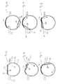
- Figures 1 illustrates a package 10 for storing and dosing a fluid according to the present invention.
- the package comprises a flexible container 1 in which a fluid is stored.
- the flexible container presents an outlet 2 connected to dosing means 3.
- This dosing means is more particularly described in relation with Figures 2a to 2f .
- the dosing means comprises a housing 31, said housing presenting a pump inlet 32 and a corresponding pump outlet 33.
- a part 34 of the housing 31 between the inlet 32 and the outlet 33 is flexible and resilient. This portion be an elastomeric material.
- This portion of the housing is between the inlet 32 and the outlet 33.
- the housing 31 can be formed of plastic like for example polyethylene or polypropylene.
- the housing 31 contains the rotor 35.
- the rotor can also be made of plastic.
- the rotor 35 is rotatable inside the housing 31.
- the rotor 35 presents at least a truncated part 37 so that when this part faces the housing part that is not flexible and resilient, this side forms a chamber 36 between the truncated rotor surface 37 and the housing.
- the rotor 35 Apart from the truncated part 37 of the rotor, the rotor 35 fits exactly inside the housing 31.
- the rotor is rotated by drive means in a clockwise direction from Fig. 2a to Fig 2f .
- a part of the truncated rotor surface 37 does not face anymore the flexible and resilient portion 34 of the housing but a rigid circular part of the housing which is creating a small chamber 36 facing the dosing means inlet 32.
- the fluid inside the inlet 32 fills the chamber 36 and this filling goes on as long as the truncated rotor surface 37 faces the dosing means inlet 32 according to Figure 2c .
- the rotor continues to turn the chamber 36 full of fluid turns too according to Figure 2d until it reaches the dosing means outlet 33 according to Figure 2e .
- the volume of the chamber 36 decreases and the fluid is urged to leave the chamber through the dosing means outlet 33 according to Figures 2e and 2f .
- the present invention is not limited to this particular embodiment of the dosing means.
- the dosing means described in WO 2006/027548 or alternatives of DE 199 16 52 can also be implemented.
- the outlet 33 of the dosing means is connected to one-way valve more preferably to a visco-elastic valve 4.
- This valve is more particularly described in relation with Figures 3a and 3b .
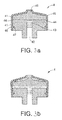
- the valve 4 comprises a delivery block 41 having an input port 42 that is connected to the dosing means outlet 5 for receiving the fluid exiting the
- the input port 42 opens into an internal channel 43 beginning in the input port and terminating in at least one output port 44.
- the valve comprises an elastomeric membrane 45 for enveloping the delivery block 41 so that a portion of said flexible elastomeric membrane covers the output ports 44.
- Figure 3a illustrates the valve when it is closed, that is when the fluid inside the channel 43 is not pressurized by the dosing means 3.
- FIG. 3b illustrates the valve when it is opened, that is when the fluid inside the channel 43 is pressurized by the dosing means 3 to a pressure sufficient to move the elastomeric membrane 45 away from the output ports 44. The fluid is then free to pass through the outlets ports 44 and circulates between the elastomeric membrane 45 and the delivery block 41 until the valve outlet 46.
- the elastomeric membrane 45 includes a protrusion 48 that can fit inside a groove 47 in the external part of the delivery block 41 to avoid the elastomeric membrane 45 sliding along the delivery block 41.
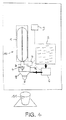
- Figure 4 illustrates a beverage and food dispensing device on which a package 10 such as described above is docked.
- the device comprises :
- control means 9 actuates the drive means 7 so that the coupling 71 rotates the rotor 35 of the dosing means 3.
- the fluid inside the container 1 is dosed by the dosing means 3 and delivered to the valve 4 and then to the mixing chamber 8.
- control means 9 actuates the diluent pump 6 so that diluent is delivered to the mixing chamber 8 where it mixes with the fluid. The mixture is then delivered to a cup 11.
- Figure 5 illustrates a dosing means comprising a housing 31 with a second pump inlet 32a and a corresponding second pump outlet 33a according to a first embodiment. Another part 34a of the housing 31 between the inlet 32a and the outlet 33a is flexible and resilient. The rotor 35 presents also a second truncated part 37a. According to this embodiment, a first fluid can be dosed at inlet 32 and delivered in outlet 33 whereas simultaneously a second fluid can be dosed at inlet 32a and delivered in outlet 33a. Each pump inlet 32, respectively 32a, is coupled to a corresponding pump outlet 33, respectively 33a.
- Figure 6 illustrates a dosing means comprises a housing 31 with a second pump inlet 32a and a second pump outlet 33a according to a second embodiment. Each couple of outlets and inlets are offset from one another on the same housing and rotor.
- inventions can be used to simultaneously dose and deliver a beverage concentrate and a diluent, the both being delivered in the same mixing chamber.
- Such embodiments present the advantage of avoiding the use of two different pumps for the two fluids.
- the diluent can be water either hot or cold for diluting a concentrated fluid.
- the diluent can also be a gas, like nitrogen or carbon dioxide, for mixing with a beverage and forming a head of foam on the beverage or for producing a sparkling beverage.
- the connections of the mixing chamber with the dosing means gas outlet and the valve delivering the beverage are made sufficiently tight so that the mixing chamber is sufficiently hermetic to atmospheric pressure and the mixing of the gas and the beverage is realised under the pressure provided by the dosing means.
- the package and the device of the present invention present the advantage of enabling a safe dispensing of microbiologically sensitive fluids.
- the pressure to be delivered by the dosing means can be adapted in function of the fluid to be delivered and in particular the viscosity of the fluid. The higher the viscosity, the more important should be the pressure delivered by the dosing means.
- the pressure delivered by the dosing means can be adjusted by the choice of the nature of the flexible and resilient part of the dosing means housing and in particular its hardness.
- Another advantage of the package and the device of the present invention is that a consistent dosing of the fluid can be reached.
- Another advantage of the package and the device of the present invention is that the fluid can be delivered in the mixing chamber under pressure and this pressure can be used for getting an efficient dissolution in the diluent but also for eventually foaming the prepared beverage in the mixing chamber.
- the shear forces of the fluids delivered by the dosing means are increased to encourage mixing.
Landscapes
- Engineering & Computer Science (AREA)
- Mechanical Engineering (AREA)
- General Engineering & Computer Science (AREA)
- Physics & Mathematics (AREA)
- Fluid Mechanics (AREA)
- General Physics & Mathematics (AREA)
- Devices For Dispensing Beverages (AREA)
- Packages (AREA)
- Containers And Packaging Bodies Having A Special Means To Remove Contents (AREA)
- Details And Applications Of Rotary Liquid Pumps (AREA)
Abstract
The invention concerns a Package for storing and dosing fluid comprising:
- a flexible container for storing a fluid and presenting a fluid outlet,
- dosing means comprising :
. a housing, said housing presenting a pump inlet and a pump outlet and a part of the housing between the inlet and the outlet being flexible and resilient,
. a rotor presenting at last one chamber formed between the rotor surface and the housing,
- a one-way valve,
wherein the housing pump inlet is connected to the flexible container and the housing pump outlet is connected to the one-way visco-elastic valve.
Description
- The present invention relates to a package presenting storing, dosing and dispensing functions and particularly adapted for dispensing microbiologically sensible food fluid products.
- One way to aseptically dispense al, microbiological sensitive fluid through a dispenser consists in storing the fluid in a bag-in-box (BIB) type container with a delivery tube comprising an aseptic one-way valve at the outlet of the tube. A type of aseptic valve consists of a so-called visco-elastic valve comprising a valve body presenting a cylinder or a truncated cone form and the valve body comprising an internal channel connected to one or several fluid delivery ports. The valve also comprises an elastomeric cylinder having an internal section smaller than the section of the valve body so that the elastomeric cylinder is tightly fitted over the fluid delivery ports and over the valve seat. Such a valve is, for example, set forth in
US 7,243,682 ,US 5,836,484 orWO 2006/063000 . - The dispensing is accomplished by the means of a pump such as a peristaltic pump that exerts a pressure on the flexible tube and on the fluid present in the tube, and then in the valve body internal channel and delivery ports. When the fluid pressure exceeds the pressure outside the valve, this pressure urges the elastic cylinder away from the valve body and the delivery ports. Fluid then flows out between the valve body and the elastic cylinder. When the pump is stopped, the pressure outside the valve body exceeds the fluid pressure and the elastic cylinder is clamped tightly against the valve body, thereby preventing flow back through the valve. Consequently flow is only permitted in one direction.
- Yet, it has been observed in such dispensers that the aseptic state between two fluid deliveries is not maintained systemwide. Depending of the valve design, the visco-elastic valves can maintain a certain back-pressure after the pump has stopped and it can take a few minutes before the fluid pressure effectively drops to a lower pressure. Then at the exact closing of the valve the status of the valve is not certain as the valve is too close to an open position to ensure a full and firm closure.
- Starting from a valve which is open and delivers a certain liquid flow, a reduction of the pressure of the liquid results in a reduced flow rate and further reduction of the pressure results in a situation where the flow rate reaches zero when the valve reaches what is called the closing pressure. At that point the check valve is in a not very stable status: it is close to being open yet is closed. This is represented by the valve typically slowly leaking a few drops of liquid thus possibly compromising the aseptic state of the remaining liquid. At that closing point, a typical valve, made with an elastomeric membrane fitted over a solid valve seat, the membrane is already fitted onto and in contact with then valve seat. However this fit is not very tight, as is demonstrated by the accumulation of a liquid droplet or dripping from the valve over a short time (up to one minute). After a minute or so of dripping, then the pressure in the delivery system upstream of the valve reaches another value where the valve is now holding a constant pressure over time called the holding pressure. During these phases the check valve is vulnerable to microbial contamination. This phenomenon has been particularly observed in situations where viscous fluids are dispensed or for fluids comprising particulates.
- Besides this phenomenon the package comprising the bag-in-box (BIB) type container with a delivery tube comprising an aseptic lone-way valve at the outlet of the tube takes up a lot of place inside a dispensing machine or during storage. The different parts of the package also use several different components of different natures and the production can be complicated and expensive.
- It has also been noticed that the use of a peristaltic pump to exert a pressure on the flexible tube does not deliver a consistent dosing. Yet the consistency of dosing is an important issue in the beverage dispensers because it influences the taste of the reconstituted beverage or food which becomes less or more diluted. In terms of product quality, the consistency of the product is important for meeting the satisfaction of the consumer. If the dose-to-dose variation is too large, it affects the in-cup quality of the product in a way that becomes perceptible for the consumer.
- An aim of the present invention is to propose a solution to the above problems.
- According to a first aspect, the invention concerns a package for storing and dosing a fluid comprising :
- a collapsible container conceived for storing a fluid and presenting a fluid outlet,
- a dosing means comprising :
- a housing, said housing presenting at least a pump inlet and at least a pump outlet and a part of the housing between the inlet and the outlet being flexible and resilient,
- a rotor inside the housing presenting at last one chamber formed between the rotor surface and the housing,
- a visco-elastic valve,
- According to the preferred embodiment the collapsible container is made of an oxygen and water barrier material. This container can be a flexible pouch, eventually stored in a rigid housing like a bag in box (BIB) container, or it can be a bottle made of a compressible material. Usually the container is made of plastic materials, such as for example laminates with or without aluminum, EVOH, PET multilayer, PPPE multilayer or all combinations of these materials. Bioplastics can also be used.
- According to another preferred embodiment the rotor of the dosing means is extended by a coupling means intended to be connected to a complementary coupling means belonging to drive means.
- Preferably the rotor of the dosing means presents several chambers. This embodiment enables the dosing means to deliver an increased volume of fluid.
- According to another preferred embodiment the flexible container stores a microbiological sensitive fluid. This fluid can be chosen in the list of the following fluids : milk based ingredient, a cocoa based ingredient, fruit juices, ... Yet any other fluids less sensible to bacteria can also be dispensed like coffee, tea, ... The fluid can also comprise particulates, these particulates preferably presenting a size of at most 200 µm. Preferably the fluid is a food or beverage ingredient concentrate that can be diluted to prepare a beverage.
- According to another preferred embodiment the package of the present invention is disposable.
- According to another preferred embodiment the visco-elastic valve of the package is a visco-elastic valve comprises a delivery block having an input port for receiving the fluid and an internal channel beginning at the input port and terminating in at least one output port, an elastomeric membrane for enveloping the delivery block such that a portion of the elastomeric membrane covers the output port and the downstream end of the elastomeric membrane forms the valve outlet.
- According to a specific embodiment the invention also concerns a package wherein the dosing means housing comprises a second pump inlet and a corresponding second pump outlet, the second housing pump inlet being connectable to a diluent supply and the second housing pump outlet being connectable to a mixing chamber.
- According to a second aspect the invention concerns a beverage and food dispensing device on which a package such as described hereabove can be docked, said device comprising :
- a diluent supply means,
- dosing drive means,
- a mixing chamber,
- a receiving area for receiving the Package and which comprises means for coupling the package dosing means with the dosing drive means and means for coupling the one-way valve with the mixing chamber,
- control means for controlling the supply of diluent and driving the dosing drive means.
- In the beverage and food dispensing device the diluent supply means can comprise a water supply duct connected to a water pump and optionally to a water heating system.
- The dosing drive means can comprise a motor and a driveshaft connected to complementary coupling means to link with the coupling means of the dosing means.
- The beverage and food dispensing device preferably comprises a controller associated with the control means and programmed to control and coordinate the activation of the dosing means drive means and the activation of the diluent supply means.
- The present invention also concerns a beverage and food dispensing device on which a package such as described above and comprising a second pump inlet and a second pump outlet can be docked. This dispensing device comprises :
- a diluent supply means,
- dosing drive means,
- a mixing chamber,
- a receiving area for receiving the package and which comprises :
- means for coupling the package dosing means with the dosing drive means,
- means for coupling the one-way valve with the mixing chamber,
- means for coupling the diluent supply means with the second pump inlet of the dosing means housing, and
- means for coupling the mixing chamber with the second pump outlet of the dosing means housing,
- control means for driving the dosing drive mean.
- According to a third aspect the invention also concerns a device for dosing and delivering a fluid, the device being able to be connected to a collapsible container, said device comprising :
- dosing means comprising :
- a housing, said housing presenting at least a pump inlet and at least a pump outlet and a part of the housing between the inlet and the outlet being flexible and resilient,
- a rotor presenting at last one chamber formed between the rotor surface and the housing,
- a visco-elastic valve,
- According to this third aspect, the device for dosing and delivering a fluid can be in the form of a cap that can be connected to a fluid container by appropriate connecting means.
- The characteristics and advantages the invention will be better understood in relation to
-
Figures 1 depict a schematic view of the package of the present invention. -
Figure 2 depicts a section view of a preferred one way valve that can be used in the package of the present invention. -
Figures 3a and 3b depict a section view of a preferred dosing means that can be used in the package of the present invention. -
Figure 4 depicts a schematic view of al beverage and food dispensing device on which a package according to the present invention is docked. -
Figures 5 and 6 depict schematic views of specific dosing means that can be used in the devices of the present invention -
Figures 1 illustrates apackage 10 for storing and dosing a fluid according to the present invention. The package comprises a flexible container 1 in which a fluid is stored. The flexible container presents anoutlet 2 connected to dosing means 3. This dosing means is more particularly described in relation withFigures 2a to 2f . - The dosing means comprises a
housing 31, said housing presenting apump inlet 32 and acorresponding pump outlet 33. A part 34 of thehousing 31 between theinlet 32 and theoutlet 33 is flexible and resilient. This portion be an elastomeric material. This portion of the housing is between theinlet 32 and theoutlet 33. Thehousing 31 can be formed of plastic like for example polyethylene or polypropylene. Thehousing 31 contains the rotor 35. The rotor can also be made of plastic. The rotor 35 is rotatable inside thehousing 31. The rotor 35 presents at least atruncated part 37 so that when this part faces the housing part that is not flexible and resilient, this side forms achamber 36 between thetruncated rotor surface 37 and the housing. Apart from thetruncated part 37 of the rotor, the rotor 35 fits exactly inside thehousing 31. The rotor is rotated by drive means in a clockwise direction fromFig. 2a to Fig 2f . InFigure 2a no fluid circulates in the dosing means. InFigure 2b , due to the rotation of the rotor, a part of thetruncated rotor surface 37 does not face anymore the flexible and resilient portion 34 of the housing but a rigid circular part of the housing which is creating asmall chamber 36 facing the dosing meansinlet 32. Then the fluid inside theinlet 32 fills thechamber 36 and this filling goes on as long as thetruncated rotor surface 37 faces the dosing meansinlet 32 according toFigure 2c . As the rotor continues to turn thechamber 36 full of fluid turns too according toFigure 2d until it reaches the dosing meansoutlet 33 according toFigure 2e . Due to the presence of the flexible and resilient portion 34 of the housing after the dosing meansoutlet 33, the volume of thechamber 36 decreases and the fluid is urged to leave the chamber through the dosing meansoutlet 33 according toFigures 2e and 2f . The present invention is not limited to this particular embodiment of the dosing means. In particular the dosing means described inWO 2006/027548 or alternatives ofDE 199 16 52 can also be implemented. - The
outlet 33 of the dosing means is connected to one-way valve more preferably to a visco-elastic valve 4. This valve is more particularly described in relation withFigures 3a and 3b . Thevalve 4 comprises adelivery block 41 having aninput port 42 that is connected to the dosing means outlet 5 for receiving the fluid exiting the Theinput port 42 opens into aninternal channel 43 beginning in the input port and terminating in at least oneoutput port 44. The valve comprises anelastomeric membrane 45 for enveloping thedelivery block 41 so that a portion of said flexible elastomeric membrane covers theoutput ports 44.Figure 3a illustrates the valve when it is closed, that is when the fluid inside thechannel 43 is not pressurized by the dosing means 3. In this configuration theelastomeric membrane 45 hermetically closes theoutput ports 44.Figure 3b illustrates the valve when it is opened, that is when the fluid inside thechannel 43 is pressurized by the dosing means 3 to a pressure sufficient to move theelastomeric membrane 45 away from theoutput ports 44. The fluid is then free to pass through theoutlets ports 44 and circulates between theelastomeric membrane 45 and thedelivery block 41 until thevalve outlet 46. Preferably theelastomeric membrane 45 includes aprotrusion 48 that can fit inside agroove 47 in the external part of thedelivery block 41 to avoid theelastomeric membrane 45 sliding along thedelivery block 41. -
Figure 4 illustrates a beverage and food dispensing device on which apackage 10 such as described above is docked. The device comprises : - a diluent supply means which consists in a water tank 5, in which the water can optionally be heated or cooled, and a pump 6.
- a mixing chamber 8 for mixing the diluent with the fluid delivered by the
package 10. - dosing drive means 7 able to be coupled to the dosing means of the
package 10. - a receiving area for receiving the
package 10 and which comprises means 71 for coupling the package dosing means 3 with the dosing drive means 7 and means for coupling/connecting the one-way valve 4 with the mixing chamber 8. The means for coupling/connecting the one-way valve 4 with the mixing chamber 8 can simply be a snap connection or any other means to attach a valve to a chamber. - control means 9 for controlling the supply of diluent via the pump 6 and driving the dosing drive means 7.
- When a beverage is prepared with the device of the present invention, the control means 9 actuates the drive means 7 so that the coupling 71 rotates the rotor 35 of the dosing means 3. The fluid inside the container 1 is dosed by the dosing means 3 and delivered to the
valve 4 and then to the mixing chamber 8. Simultaneously the control means 9 actuates the diluent pump 6 so that diluent is delivered to the mixing chamber 8 where it mixes with the fluid. The mixture is then delivered to a cup 11. -
Figure 5 illustrates a dosing means comprising ahousing 31 with a second pump inlet 32a and a corresponding second pump outlet 33a according to a first embodiment. Another part 34a of thehousing 31 between the inlet 32a and the outlet 33a is flexible and resilient. The rotor 35 presents also a second truncated part 37a. According to this embodiment, a first fluid can be dosed atinlet 32 and delivered inoutlet 33 whereas simultaneously a second fluid can be dosed at inlet 32a and delivered in outlet 33a. Eachpump inlet 32, respectively 32a, is coupled to acorresponding pump outlet 33, respectively 33a. -
Figure 6 illustrates a dosing means comprises ahousing 31 with a second pump inlet 32a and a second pump outlet 33a according to a second embodiment. Each couple of outlets and inlets are offset from one another on the same housing and rotor. - These embodiments can be used to simultaneously dose and deliver a beverage concentrate and a diluent, the both being delivered in the same mixing chamber. Such embodiments present the advantage of avoiding the use of two different pumps for the two fluids. Besides the two fluids can be delivered under pressure and effective mixing and eventually foaming can be reached. The diluent can be water either hot or cold for diluting a concentrated fluid. The diluent can also be a gas, like nitrogen or carbon dioxide, for mixing with a beverage and forming a head of foam on the beverage or for producing a sparkling beverage. In this latter embodiment, the connections of the mixing chamber with the dosing means gas outlet and the valve delivering the beverage are made sufficiently tight so that the mixing chamber is sufficiently hermetic to atmospheric pressure and the mixing of the gas and the beverage is realised under the pressure provided by the dosing means..
- The package and the device of the present invention present the advantage of enabling a safe dispensing of microbiologically sensitive fluids. First the integration of the dosing means such as described above in the any upstream of the visco-elastic valve creates a pressure important and stable during the of the fluid. This pressure can reach around 6 bars. Due to this high pressure the valve easily opens but also easily returns back at rest when the dosing means stops pumping. The valve closes immediately after the pump is stopped. No dripping occurs after the pump has stopped pumping.
- The pressure to be delivered by the dosing means can be adapted in function of the fluid to be delivered and in particular the viscosity of the fluid. The higher the viscosity, the more important should be the pressure delivered by the dosing means. The pressure delivered by the dosing means can be adjusted by the choice of the nature of the flexible and resilient part of the dosing means housing and in particular its hardness.
- Another advantage of the package and the device of the present invention is that a consistent dosing of the fluid can be reached.
- Another advantage of the package and the device of the present invention is that the fluid can be delivered in the mixing chamber under pressure and this pressure can be used for getting an efficient dissolution in the diluent but also for eventually foaming the prepared beverage in the mixing chamber. Actually the shear forces of the fluids delivered by the dosing means are increased to encourage mixing.
Claims (14)
- Package for storing and dosing a fluid comprising:- a collapsible container for storing a fluid and presenting a fluid outlet,- dosing means comprising :. a housing, said housing presenting at least a pump inlet and at least a pump outlet and a part of the housing between the outlet and the inlet being flexible and resilient,. a rotor presenting at last one chamber formed between the rotor surface and the housing,- a visco-elastic valve,wherein the housing pump inlet is connected to the collapsible container and the housing pump outlet is connected to the visco-elastic valve.
- Package according to Claim 1 wherein the rotor of the dosing means is extended by a coupling means intended to be connected to a complementary coupling means belonging to drive means.
- Package according to Claim 1 or 2 wherein the rotor of the dosing means presents several chambers.
- Package according to any of the precedent claims wherein the collapsible container stores a microbiological sensitive fluid.
- Package according to any of the precedent claims wherein the collapsible container stores a food or beverage ingredient concentrate.
- Package according to any of the precedent claims characterized in that it is disposable
- Package according to any of the precedent claims wherein the visco-elastic valve comprises a delivery block (41) having an input port (42) for receiving the fluid and an internal channel beginning at the input port and terminating in at least one output port (44), an elastomeric membrane (45) for enveloping the delivery block such that a portion of the elastomeric membrane covers the output port and the downstream end of the elastomeric membrane forms the valve outlet.
- Package according to any of the precedent claims wherein the dosing means housing comprises a second pump inlet and a second pump outlet, the second housing pump inlet being connectable to a diluent supply and the Second housing pump outlet being connectable to a mixing chamber.
- Beverage and food dispensing device on which a package according to any of claims 1 to 7 can be docked comprising :- a diluent supply means,- dosing drive means,- a mixing chamber,- a receiving area for receiving the package and which comprises means for coupling the package dosing means with the dosing drive means and means for coupling the one-way valve with the mixing chamber,- control means for controlling the supply of diluent and driving the dosing drive means.
- Beverage and food dispensing device according to Claim 9 wherein the diluent supply means comprises a water supply duct connected to a water pump and optionally to a water heating or cooling system.
- Beverage and food dispensing device according to Claim 9 or 10 wherein the dosing means drive means comprise a motor and a driveshaft connected to the complementary coupling means to link with the coupling means of the liquid pump.
- Beverage and food dispensing device according to any of claims 9 to 11 wherein it further comprises a controller associated with the control means and programmed to control and coordinate the activation of the dosing means drive means and the activation of the diluent supply means.
- Beverage and food dispensing device on which a package according to claim 8 can be docked comprising :- a diluent supply means,- dosing drive means,- a mixing chamber,- a receiving area for receiving the package and which comprises :. means for coupling the package dosing means with the dosing drive means,. means for coupling the one-way valve with the mixing chamber,. means for coupling the diluent supply means with the second pump inlet of the dosing means housing, and. means for coupling the mixing chamber with the second pump outlet of the dosing means housing,- control means for driving the dosing drive means.
- Device for dosing and delivering a fluid, the devide being able to be connected to a collapsible container, said device comprising:- dosing means comprising :. a housing, said housing presenting at least a pump inlet and at least a pump outlet and a part of the housing between the inlet and the outlet being flexible and resilient,. a rotor presenting at last one chamber formed between the rotor surface and the housing,- a visco-elastic valve,wherein the housing pump outlet is connected to the visco-elastic valve.
Priority Applications (12)
| Application Number | Priority Date | Filing Date | Title |
|---|---|---|---|
| EP10161618A EP2383553A1 (en) | 2010-04-30 | 2010-04-30 | Package for storing and dosing a fluid |
| CN2011800218383A CN103168215A (en) | 2010-04-30 | 2011-04-20 | Package for storing and dosing a fluid and dispenser for docking the package |
| MX2012012350A MX2012012350A (en) | 2010-04-30 | 2011-04-20 | Package for storing and dosing a fluid and dispenser for docking the package. |
| SG2012078440A SG184993A1 (en) | 2010-04-30 | 2011-04-20 | Package for storing and dosing a fluid and dispenser for docking the package |
| EP11715706A EP2564172A2 (en) | 2010-04-30 | 2011-04-20 | Package for storing and dosing a fluid and dispenser for docking the package |
| US13/695,348 US20130043274A1 (en) | 2010-04-30 | 2011-04-20 | Package for storing and dosing a fluid and dispenser for docking the package |
| RU2012151260/28A RU2012151260A (en) | 2010-04-30 | 2011-04-20 | FLUID STORAGE AND DOSING UNIT AND FILLING UNIT WITH SUCH AN UNIT |
| CA2797587A CA2797587A1 (en) | 2010-04-30 | 2011-04-20 | Package for storing and dosing a fluid and dispenser for docking the package |
| PCT/EP2011/056312 WO2011134858A2 (en) | 2010-04-30 | 2011-04-20 | Package for storing and dosing a fluid and dispenser for docking the package |
| JP2013506591A JP2013534984A (en) | 2010-04-30 | 2011-04-20 | Package for storing and dispensing fluid, and dispensing device for docking the package |
| AU2011246534A AU2011246534A1 (en) | 2010-04-30 | 2011-04-20 | Package for storing and dosing a fluid and dispenser for docking the package |
| ZA2012/09044A ZA201209044B (en) | 2010-04-30 | 2012-11-29 | Package for storing and dosing a fluid and dispenser for docking the package |
Applications Claiming Priority (1)
| Application Number | Priority Date | Filing Date | Title |
|---|---|---|---|
| EP10161618A EP2383553A1 (en) | 2010-04-30 | 2010-04-30 | Package for storing and dosing a fluid |
Publications (1)
| Publication Number | Publication Date |
|---|---|
| EP2383553A1 true EP2383553A1 (en) | 2011-11-02 |
Family
ID=42751883
Family Applications (2)
| Application Number | Title | Priority Date | Filing Date |
|---|---|---|---|
| EP10161618A Withdrawn EP2383553A1 (en) | 2010-04-30 | 2010-04-30 | Package for storing and dosing a fluid |
| EP11715706A Withdrawn EP2564172A2 (en) | 2010-04-30 | 2011-04-20 | Package for storing and dosing a fluid and dispenser for docking the package |
Family Applications After (1)
| Application Number | Title | Priority Date | Filing Date |
|---|---|---|---|
| EP11715706A Withdrawn EP2564172A2 (en) | 2010-04-30 | 2011-04-20 | Package for storing and dosing a fluid and dispenser for docking the package |
Country Status (11)
| Country | Link |
|---|---|
| US (1) | US20130043274A1 (en) |
| EP (2) | EP2383553A1 (en) |
| JP (1) | JP2013534984A (en) |
| CN (1) | CN103168215A (en) |
| AU (1) | AU2011246534A1 (en) |
| CA (1) | CA2797587A1 (en) |
| MX (1) | MX2012012350A (en) |
| RU (1) | RU2012151260A (en) |
| SG (1) | SG184993A1 (en) |
| WO (1) | WO2011134858A2 (en) |
| ZA (1) | ZA201209044B (en) |
Cited By (6)
| Publication number | Priority date | Publication date | Assignee | Title |
|---|---|---|---|---|
| WO2014135563A1 (en) * | 2013-03-05 | 2014-09-12 | Quantex Patents Limited | Pumps |
| CN104271019A (en) * | 2012-02-14 | 2015-01-07 | 高乔工业股份有限公司 | Two-fluid pump |
| WO2015197505A1 (en) * | 2014-06-25 | 2015-12-30 | Nestec S.A. | Disposable foaming device |
| WO2018010889A1 (en) * | 2016-07-14 | 2018-01-18 | F. Holzer Gmbh | Pump head and metering device |
| WO2018010890A1 (en) * | 2016-07-14 | 2018-01-18 | F. Holzer Gmbh | Pump head and metering device |
| WO2020049005A1 (en) * | 2018-09-03 | 2020-03-12 | Quantex Patents Limited | Beverage dispenser head for mixing concentrate, diluent and additive |
Families Citing this family (6)
| Publication number | Priority date | Publication date | Assignee | Title |
|---|---|---|---|---|
| US8870025B2 (en) * | 2009-10-23 | 2014-10-28 | Nestec S.A. | Method and device for aseptically dispensing multiple portions of a fluid |
| EP2490982B1 (en) * | 2009-10-23 | 2015-02-25 | Nestec S.A. | Method for aseptically dispensing multiple portions of a fluid |
| EP3322539A1 (en) | 2015-07-15 | 2018-05-23 | Gary Rayner | Systems and methods for producing a foamable and/or flowable material for consumption |
| US10945555B2 (en) | 2015-11-05 | 2021-03-16 | Societe Des Produits Nestle S.A. | Centrifugal pumping and foaming device |
| PT3373781T (en) | 2015-11-13 | 2020-01-14 | Nestle Sa | Foaming device |
| WO2019038143A1 (en) | 2017-08-25 | 2019-02-28 | Nestec S.A. | Inline fluid foaming device |
Citations (12)
| Publication number | Priority date | Publication date | Assignee | Title |
|---|---|---|---|---|
| US4717047A (en) * | 1977-08-08 | 1988-01-05 | Douwe Egberts Koninklijke Tabaksfabriek-Koffiebranderijen-Theehandel B.V. | Disposable coffee concentrate storing and transporting apparatus |
| US5279447A (en) * | 1992-08-12 | 1994-01-18 | Reseal International Limited Partnership | Fluid dispensing unit with metered outflow |
| US5305923A (en) * | 1990-06-06 | 1994-04-26 | The Coca-Cola Company | Postmix beverage dispensing system |
| US5615801A (en) * | 1990-06-06 | 1997-04-01 | The Coca-Cola Company | Juice concentrate package for postmix dispenser |
| US5836484A (en) | 1996-10-03 | 1998-11-17 | Gerber; Bernard R. | Contamination-safe multiple-dose dispensing cartridge for flowable materials |
| DE19916252A1 (en) | 1999-04-12 | 2000-11-02 | Hoka Gmbh | Pump for low-volume delivery comprises rotating shaft with flat surface region in housing incorporating section consisting of flexible foil |
| WO2006027548A1 (en) | 2004-09-07 | 2006-03-16 | Pdd Innovations Limited | Rotary pump with resiliently deformed seal |
| WO2006063000A2 (en) | 2004-12-04 | 2006-06-15 | Medical Instill Technologies, Inc. | One-way valve, apparatus and method of using the valve |
| US20070068966A1 (en) * | 2005-09-23 | 2007-03-29 | Orzech Thomas S | Food dispenser with pump for easy loading of containers therein |
| US7243682B2 (en) | 2003-10-02 | 2007-07-17 | Brandes Raymond V | Annular one-way valve |
| WO2007133297A2 (en) * | 2006-01-05 | 2007-11-22 | Medical Instill Technologies, Inc. | One-way valve and apparatus and method of using the valve |
| EP2017221A1 (en) * | 2007-07-19 | 2009-01-21 | Nestec, Ltd. | Device for dispensing a liquid |
Family Cites Families (11)
| Publication number | Priority date | Publication date | Assignee | Title |
|---|---|---|---|---|
| US3869067A (en) * | 1972-06-26 | 1975-03-04 | Du Pont | Apparatus for gradient elution |
| US4651862A (en) * | 1985-06-10 | 1987-03-24 | Greenfield Jr Irving E | Dual temperature beverage dispenser with removable operating module |
| JPH11245997A (en) * | 1998-02-27 | 1999-09-14 | Sanyo Electric Co Ltd | Drink dispenser |
| US6364159B1 (en) * | 2000-05-01 | 2002-04-02 | The Coca Cola Company | Self-monitoring, intelligent fountain dispenser |
| US6892899B2 (en) * | 2002-10-16 | 2005-05-17 | Carrier Commerical Refrigeration, Inc. | Passive syrup delivery system |
| US20040144799A1 (en) * | 2003-01-24 | 2004-07-29 | Baxter International Inc. | Liquid dispenser and flexible bag therefor |
| US20060249536A1 (en) * | 2005-05-09 | 2006-11-09 | Hartman Eric E | Device and method for dispensing a food product using a reclosable resilient valve |
| US7537138B2 (en) * | 2005-06-20 | 2009-05-26 | Nestec S.A. | Methods and systems for delivering foamed beverages from liquid concentrates |
| US7651010B2 (en) * | 2005-09-23 | 2010-01-26 | Nestec S.A. | Food dispenser with pump for dispensing from a plurality of sources |
| US8087544B2 (en) * | 2006-08-23 | 2012-01-03 | Kyle B Elsom | System for mixing beverage components in a predetermined ratio |
| ATE481353T1 (en) * | 2007-07-19 | 2010-10-15 | Nestec Ltd | DEVICE FOR DISPENSING A LIQUID |
-
2010
- 2010-04-30 EP EP10161618A patent/EP2383553A1/en not_active Withdrawn
-
2011
- 2011-04-20 AU AU2011246534A patent/AU2011246534A1/en not_active Abandoned
- 2011-04-20 WO PCT/EP2011/056312 patent/WO2011134858A2/en active Application Filing
- 2011-04-20 MX MX2012012350A patent/MX2012012350A/en active IP Right Grant
- 2011-04-20 JP JP2013506591A patent/JP2013534984A/en not_active Withdrawn
- 2011-04-20 CA CA2797587A patent/CA2797587A1/en not_active Abandoned
- 2011-04-20 RU RU2012151260/28A patent/RU2012151260A/en not_active Application Discontinuation
- 2011-04-20 EP EP11715706A patent/EP2564172A2/en not_active Withdrawn
- 2011-04-20 CN CN2011800218383A patent/CN103168215A/en active Pending
- 2011-04-20 SG SG2012078440A patent/SG184993A1/en unknown
- 2011-04-20 US US13/695,348 patent/US20130043274A1/en not_active Abandoned
-
2012
- 2012-11-29 ZA ZA2012/09044A patent/ZA201209044B/en unknown
Patent Citations (12)
| Publication number | Priority date | Publication date | Assignee | Title |
|---|---|---|---|---|
| US4717047A (en) * | 1977-08-08 | 1988-01-05 | Douwe Egberts Koninklijke Tabaksfabriek-Koffiebranderijen-Theehandel B.V. | Disposable coffee concentrate storing and transporting apparatus |
| US5305923A (en) * | 1990-06-06 | 1994-04-26 | The Coca-Cola Company | Postmix beverage dispensing system |
| US5615801A (en) * | 1990-06-06 | 1997-04-01 | The Coca-Cola Company | Juice concentrate package for postmix dispenser |
| US5279447A (en) * | 1992-08-12 | 1994-01-18 | Reseal International Limited Partnership | Fluid dispensing unit with metered outflow |
| US5836484A (en) | 1996-10-03 | 1998-11-17 | Gerber; Bernard R. | Contamination-safe multiple-dose dispensing cartridge for flowable materials |
| DE19916252A1 (en) | 1999-04-12 | 2000-11-02 | Hoka Gmbh | Pump for low-volume delivery comprises rotating shaft with flat surface region in housing incorporating section consisting of flexible foil |
| US7243682B2 (en) | 2003-10-02 | 2007-07-17 | Brandes Raymond V | Annular one-way valve |
| WO2006027548A1 (en) | 2004-09-07 | 2006-03-16 | Pdd Innovations Limited | Rotary pump with resiliently deformed seal |
| WO2006063000A2 (en) | 2004-12-04 | 2006-06-15 | Medical Instill Technologies, Inc. | One-way valve, apparatus and method of using the valve |
| US20070068966A1 (en) * | 2005-09-23 | 2007-03-29 | Orzech Thomas S | Food dispenser with pump for easy loading of containers therein |
| WO2007133297A2 (en) * | 2006-01-05 | 2007-11-22 | Medical Instill Technologies, Inc. | One-way valve and apparatus and method of using the valve |
| EP2017221A1 (en) * | 2007-07-19 | 2009-01-21 | Nestec, Ltd. | Device for dispensing a liquid |
Cited By (24)
| Publication number | Priority date | Publication date | Assignee | Title |
|---|---|---|---|---|
| CN104271019A (en) * | 2012-02-14 | 2015-01-07 | 高乔工业股份有限公司 | Two-fluid pump |
| CN105209759A (en) * | 2013-03-05 | 2015-12-30 | 宽泰克斯专利有限公司 | Pumps |
| CN105209759B (en) * | 2013-03-05 | 2017-03-08 | 宽泰克斯专利有限公司 | Pump |
| WO2014135563A1 (en) * | 2013-03-05 | 2014-09-12 | Quantex Patents Limited | Pumps |
| US9995296B2 (en) | 2013-03-05 | 2018-06-12 | Quantex Patents Limited | Pumps |
| RU2684448C2 (en) * | 2014-06-25 | 2019-04-09 | Нестек С.А. | Disposable foaming device |
| WO2015197505A1 (en) * | 2014-06-25 | 2015-12-30 | Nestec S.A. | Disposable foaming device |
| US11510521B2 (en) | 2014-06-25 | 2022-11-29 | Societe Des Produits Nestle S.A. | Disposable foaming device |
| RU2747671C2 (en) * | 2016-07-14 | 2021-05-12 | Ф. Хольцер Гмбх | Dispenser and dosing device |
| AU2017295388B2 (en) * | 2016-07-14 | 2022-02-10 | F. Holzer Gmbh | Pump head and metering device |
| WO2018010889A1 (en) * | 2016-07-14 | 2018-01-18 | F. Holzer Gmbh | Pump head and metering device |
| RU2737137C2 (en) * | 2016-07-14 | 2020-11-25 | Ф. Хольцер Гмбх | Batcher and dosage device |
| WO2018010890A1 (en) * | 2016-07-14 | 2018-01-18 | F. Holzer Gmbh | Pump head and metering device |
| AU2017295387B2 (en) * | 2016-07-14 | 2022-06-02 | F. Holzer Gmbh | Pump head and metering device |
| EP3491345B1 (en) | 2016-07-14 | 2021-08-04 | F. Holzer GmbH | Pump head and dosing device |
| CN109661564A (en) * | 2016-07-14 | 2019-04-19 | F·霍尔泽股份有限公司 | Pump head and measuring equipment |
| US11110472B2 (en) | 2016-07-14 | 2021-09-07 | F. Holzer Gmbh | Pump head and metering device |
| US11221248B2 (en) | 2016-07-14 | 2022-01-11 | F. Holzer Gmbh | Pump head and metering device |
| CN113272245A (en) * | 2018-09-03 | 2021-08-17 | 宽泰克斯专利有限公司 | Beverage dispenser head for mixing concentrates, diluents and additives |
| GB2590834A (en) * | 2018-09-03 | 2021-07-07 | Quantex Patents Ltd | Beverage dispenser head for mixing concentrate, diluent and additive |
| GB2590834B (en) * | 2018-09-03 | 2022-06-15 | Quantex Patents Ltd | Beverage dispenser head for mixing concentrate, diluent and additive |
| WO2020049005A1 (en) * | 2018-09-03 | 2020-03-12 | Quantex Patents Limited | Beverage dispenser head for mixing concentrate, diluent and additive |
| US11542142B2 (en) | 2018-09-03 | 2023-01-03 | Quantex Arc Limited | Beverage dispenser head for mixing concentrate, diluent and additive |
| US11858797B2 (en) | 2018-09-03 | 2024-01-02 | Quantex Arc Limited | Beverage dispenser head for mixing concentrate, diluent and additive |
Also Published As
| Publication number | Publication date |
|---|---|
| WO2011134858A3 (en) | 2015-07-09 |
| AU2011246534A1 (en) | 2012-11-22 |
| US20130043274A1 (en) | 2013-02-21 |
| EP2564172A2 (en) | 2013-03-06 |
| CN103168215A (en) | 2013-06-19 |
| JP2013534984A (en) | 2013-09-09 |
| WO2011134858A2 (en) | 2011-11-03 |
| RU2012151260A (en) | 2014-06-10 |
| CA2797587A1 (en) | 2011-11-03 |
| MX2012012350A (en) | 2012-11-16 |
| SG184993A1 (en) | 2012-11-29 |
| ZA201209044B (en) | 2014-05-28 |
Similar Documents
| Publication | Publication Date | Title |
|---|---|---|
| EP2383553A1 (en) | Package for storing and dosing a fluid | |
| EP2417052B1 (en) | Mixing nozzle fitment and mixed liquid dispenser | |
| US8371477B2 (en) | Device for dispensing a beverage with a controlled air inlet, and method thereof | |
| AU2008277621B2 (en) | Device for dispensing a liquid | |
| EP2022379B1 (en) | Single piece device for storing, metering and mixing a powder with a diluent | |
| US9242786B2 (en) | Method and device for aseptically dispensing multiple portions of a fluid | |
| US9423041B2 (en) | Dispensing machine valve and method | |
| US8870025B2 (en) | Method and device for aseptically dispensing multiple portions of a fluid | |
| WO2009010418A2 (en) | Device for dispensing a liquid | |
| CN105982554B (en) | Container with a lid | |
| JP2017534535A (en) | Distribution system | |
| EP3288433B1 (en) | Vacuum side air vent | |
| ES2698125T3 (en) | Beverage dispensing system | |
| WO2017116388A1 (en) | Mixing nozzle fitment |
Legal Events
| Date | Code | Title | Description |
|---|---|---|---|
| AK | Designated contracting states |
Kind code of ref document: A1 Designated state(s): AT BE BG CH CY CZ DE DK EE ES FI FR GB GR HR HU IE IS IT LI LT LU LV MC MK MT NL NO PL PT RO SE SI SK SM TR |
|
| AX | Request for extension of the european patent |
Extension state: AL BA ME RS |
|
| PUAI | Public reference made under article 153(3) epc to a published international application that has entered the european phase |
Free format text: ORIGINAL CODE: 0009012 |
|
| STAA | Information on the status of an ep patent application or granted ep patent |
Free format text: STATUS: THE APPLICATION HAS BEEN WITHDRAWN |
|
| 18W | Application withdrawn |
Effective date: 20120504 |