EP2348982B1 - Système pour déterminer la position de la pointe d'un cathéter médical à l'intérieur du corps d'un patient - Google Patents
Système pour déterminer la position de la pointe d'un cathéter médical à l'intérieur du corps d'un patient Download PDFInfo
- Publication number
- EP2348982B1 EP2348982B1 EP09831148.3A EP09831148A EP2348982B1 EP 2348982 B1 EP2348982 B1 EP 2348982B1 EP 09831148 A EP09831148 A EP 09831148A EP 2348982 B1 EP2348982 B1 EP 2348982B1
- Authority
- EP
- European Patent Office
- Prior art keywords
- catheter
- mps
- mapping
- processor
- imager
- Prior art date
- Legal status (The legal status is an assumption and is not a legal conclusion. Google has not performed a legal analysis and makes no representation as to the accuracy of the status listed.)
- Active
Links
- 210000000056 organ Anatomy 0.000 claims description 189
- 238000013507 mapping Methods 0.000 claims description 184
- 239000003550 marker Substances 0.000 claims description 34
- 230000005672 electromagnetic field Effects 0.000 claims description 18
- 238000002604 ultrasonography Methods 0.000 claims description 16
- 230000033001 locomotion Effects 0.000 claims description 14
- 238000002591 computed tomography Methods 0.000 claims description 6
- 238000012014 optical coherence tomography Methods 0.000 claims description 4
- 238000003325 tomography Methods 0.000 claims 1
- 238000000034 method Methods 0.000 description 98
- 238000002608 intravascular ultrasound Methods 0.000 description 57
- 244000208734 Pisonia aculeata Species 0.000 description 28
- 238000003384 imaging method Methods 0.000 description 23
- 230000004927 fusion Effects 0.000 description 10
- 230000000694 effects Effects 0.000 description 6
- 230000000747 cardiac effect Effects 0.000 description 4
- 238000012545 processing Methods 0.000 description 4
- 238000002583 angiography Methods 0.000 description 3
- 210000004072 lung Anatomy 0.000 description 3
- 238000002324 minimally invasive surgery Methods 0.000 description 3
- 206010003210 Arteriosclerosis Diseases 0.000 description 2
- 230000002159 abnormal effect Effects 0.000 description 2
- 238000002399 angioplasty Methods 0.000 description 2
- 230000006793 arrhythmia Effects 0.000 description 2
- 206010003119 arrhythmia Diseases 0.000 description 2
- 210000001367 artery Anatomy 0.000 description 2
- TZCXTZWJZNENPQ-UHFFFAOYSA-L barium sulfate Chemical compound [Ba+2].[O-]S([O-])(=O)=O TZCXTZWJZNENPQ-UHFFFAOYSA-L 0.000 description 2
- 210000004204 blood vessel Anatomy 0.000 description 2
- 239000004020 conductor Substances 0.000 description 2
- 210000004351 coronary vessel Anatomy 0.000 description 2
- 238000001514 detection method Methods 0.000 description 2
- 230000006870 function Effects 0.000 description 2
- 239000000463 material Substances 0.000 description 2
- 238000005259 measurement Methods 0.000 description 2
- 238000013138 pruning Methods 0.000 description 2
- 230000000241 respiratory effect Effects 0.000 description 2
- 230000029058 respiratory gaseous exchange Effects 0.000 description 2
- 230000033764 rhythmic process Effects 0.000 description 2
- 238000001356 surgical procedure Methods 0.000 description 2
- 230000001360 synchronised effect Effects 0.000 description 2
- 230000009466 transformation Effects 0.000 description 2
- 238000012285 ultrasound imaging Methods 0.000 description 2
- 208000037260 Atherosclerotic Plaque Diseases 0.000 description 1
- 241000270295 Serpentes Species 0.000 description 1
- 238000002679 ablation Methods 0.000 description 1
- 238000013459 approach Methods 0.000 description 1
- 208000011775 arteriosclerosis disease Diseases 0.000 description 1
- 238000004364 calculation method Methods 0.000 description 1
- 125000004122 cyclic group Chemical group 0.000 description 1
- 238000003745 diagnosis Methods 0.000 description 1
- 238000002059 diagnostic imaging Methods 0.000 description 1
- 201000010099 disease Diseases 0.000 description 1
- 208000037265 diseases, disorders, signs and symptoms Diseases 0.000 description 1
- 238000011156 evaluation Methods 0.000 description 1
- 210000002837 heart atrium Anatomy 0.000 description 1
- 230000003993 interaction Effects 0.000 description 1
- 229910052751 metal Inorganic materials 0.000 description 1
- 239000002184 metal Substances 0.000 description 1
- 238000005457 optimization Methods 0.000 description 1
- 238000002600 positron emission tomography Methods 0.000 description 1
- 238000004445 quantitative analysis Methods 0.000 description 1
- 238000009877 rendering Methods 0.000 description 1
- 230000003252 repetitive effect Effects 0.000 description 1
- 230000004044 response Effects 0.000 description 1
- 230000011218 segmentation Effects 0.000 description 1
- 230000036962 time dependent Effects 0.000 description 1
- 230000001960 triggered effect Effects 0.000 description 1
- 238000010200 validation analysis Methods 0.000 description 1
- 210000003462 vein Anatomy 0.000 description 1
Images


Classifications
-
- A—HUMAN NECESSITIES
- A61—MEDICAL OR VETERINARY SCIENCE; HYGIENE
- A61B—DIAGNOSIS; SURGERY; IDENTIFICATION
- A61B5/00—Measuring for diagnostic purposes; Identification of persons
- A61B5/06—Devices, other than using radiation, for detecting or locating foreign bodies ; determining position of probes within or on the body of the patient
-
- A—HUMAN NECESSITIES
- A61—MEDICAL OR VETERINARY SCIENCE; HYGIENE
- A61B—DIAGNOSIS; SURGERY; IDENTIFICATION
- A61B34/00—Computer-aided surgery; Manipulators or robots specially adapted for use in surgery
- A61B34/20—Surgical navigation systems; Devices for tracking or guiding surgical instruments, e.g. for frameless stereotaxis
-
- A—HUMAN NECESSITIES
- A61—MEDICAL OR VETERINARY SCIENCE; HYGIENE
- A61B—DIAGNOSIS; SURGERY; IDENTIFICATION
- A61B5/00—Measuring for diagnostic purposes; Identification of persons
- A61B5/06—Devices, other than using radiation, for detecting or locating foreign bodies ; determining position of probes within or on the body of the patient
- A61B5/061—Determining position of a probe within the body employing means separate from the probe, e.g. sensing internal probe position employing impedance electrodes on the surface of the body
- A61B5/062—Determining position of a probe within the body employing means separate from the probe, e.g. sensing internal probe position employing impedance electrodes on the surface of the body using magnetic field
-
- A—HUMAN NECESSITIES
- A61—MEDICAL OR VETERINARY SCIENCE; HYGIENE
- A61B—DIAGNOSIS; SURGERY; IDENTIFICATION
- A61B5/00—Measuring for diagnostic purposes; Identification of persons
- A61B5/06—Devices, other than using radiation, for detecting or locating foreign bodies ; determining position of probes within or on the body of the patient
- A61B5/065—Determining position of the probe employing exclusively positioning means located on or in the probe, e.g. using position sensors arranged on the probe
- A61B5/066—Superposing sensor position on an image of the patient, e.g. obtained by ultrasound or x-ray imaging
-
- A—HUMAN NECESSITIES
- A61—MEDICAL OR VETERINARY SCIENCE; HYGIENE
- A61B—DIAGNOSIS; SURGERY; IDENTIFICATION
- A61B5/00—Measuring for diagnostic purposes; Identification of persons
- A61B5/24—Detecting, measuring or recording bioelectric or biomagnetic signals of the body or parts thereof
- A61B5/316—Modalities, i.e. specific diagnostic methods
- A61B5/318—Heart-related electrical modalities, e.g. electrocardiography [ECG]
- A61B5/33—Heart-related electrical modalities, e.g. electrocardiography [ECG] specially adapted for cooperation with other devices
-
- A—HUMAN NECESSITIES
- A61—MEDICAL OR VETERINARY SCIENCE; HYGIENE
- A61B—DIAGNOSIS; SURGERY; IDENTIFICATION
- A61B5/00—Measuring for diagnostic purposes; Identification of persons
- A61B5/68—Arrangements of detecting, measuring or recording means, e.g. sensors, in relation to patient
- A61B5/6846—Arrangements of detecting, measuring or recording means, e.g. sensors, in relation to patient specially adapted to be brought in contact with an internal body part, i.e. invasive
- A61B5/6847—Arrangements of detecting, measuring or recording means, e.g. sensors, in relation to patient specially adapted to be brought in contact with an internal body part, i.e. invasive mounted on an invasive device
- A61B5/6852—Catheters
-
- A—HUMAN NECESSITIES
- A61—MEDICAL OR VETERINARY SCIENCE; HYGIENE
- A61B—DIAGNOSIS; SURGERY; IDENTIFICATION
- A61B5/00—Measuring for diagnostic purposes; Identification of persons
- A61B5/68—Arrangements of detecting, measuring or recording means, e.g. sensors, in relation to patient
- A61B5/6846—Arrangements of detecting, measuring or recording means, e.g. sensors, in relation to patient specially adapted to be brought in contact with an internal body part, i.e. invasive
- A61B5/6867—Arrangements of detecting, measuring or recording means, e.g. sensors, in relation to patient specially adapted to be brought in contact with an internal body part, i.e. invasive specially adapted to be attached or implanted in a specific body part
- A61B5/6876—Blood vessel
-
- A—HUMAN NECESSITIES
- A61—MEDICAL OR VETERINARY SCIENCE; HYGIENE
- A61B—DIAGNOSIS; SURGERY; IDENTIFICATION
- A61B5/00—Measuring for diagnostic purposes; Identification of persons
- A61B5/72—Signal processing specially adapted for physiological signals or for diagnostic purposes
- A61B5/7271—Specific aspects of physiological measurement analysis
- A61B5/7285—Specific aspects of physiological measurement analysis for synchronising or triggering a physiological measurement or image acquisition with a physiological event or waveform, e.g. an ECG signal
-
- A—HUMAN NECESSITIES
- A61—MEDICAL OR VETERINARY SCIENCE; HYGIENE
- A61B—DIAGNOSIS; SURGERY; IDENTIFICATION
- A61B5/00—Measuring for diagnostic purposes; Identification of persons
- A61B5/74—Details of notification to user or communication with user or patient ; user input means
- A61B5/742—Details of notification to user or communication with user or patient ; user input means using visual displays
- A61B5/743—Displaying an image simultaneously with additional graphical information, e.g. symbols, charts, function plots
-
- A—HUMAN NECESSITIES
- A61—MEDICAL OR VETERINARY SCIENCE; HYGIENE
- A61B—DIAGNOSIS; SURGERY; IDENTIFICATION
- A61B6/00—Apparatus for radiation diagnosis, e.g. combined with radiation therapy equipment
- A61B6/52—Devices using data or image processing specially adapted for radiation diagnosis
- A61B6/5211—Devices using data or image processing specially adapted for radiation diagnosis involving processing of medical diagnostic data
- A61B6/5229—Devices using data or image processing specially adapted for radiation diagnosis involving processing of medical diagnostic data combining image data of a patient, e.g. combining a functional image with an anatomical image
- A61B6/5247—Devices using data or image processing specially adapted for radiation diagnosis involving processing of medical diagnostic data combining image data of a patient, e.g. combining a functional image with an anatomical image combining images from an ionising-radiation diagnostic technique and a non-ionising radiation diagnostic technique, e.g. X-ray and ultrasound
-
- A—HUMAN NECESSITIES
- A61—MEDICAL OR VETERINARY SCIENCE; HYGIENE
- A61B—DIAGNOSIS; SURGERY; IDENTIFICATION
- A61B8/00—Diagnosis using ultrasonic, sonic or infrasonic waves
- A61B8/12—Diagnosis using ultrasonic, sonic or infrasonic waves in body cavities or body tracts, e.g. by using catheters
-
- A—HUMAN NECESSITIES
- A61—MEDICAL OR VETERINARY SCIENCE; HYGIENE
- A61B—DIAGNOSIS; SURGERY; IDENTIFICATION
- A61B8/00—Diagnosis using ultrasonic, sonic or infrasonic waves
- A61B8/42—Details of probe positioning or probe attachment to the patient
- A61B8/4245—Details of probe positioning or probe attachment to the patient involving determining the position of the probe, e.g. with respect to an external reference frame or to the patient
- A61B8/4254—Details of probe positioning or probe attachment to the patient involving determining the position of the probe, e.g. with respect to an external reference frame or to the patient using sensors mounted on the probe
-
- A—HUMAN NECESSITIES
- A61—MEDICAL OR VETERINARY SCIENCE; HYGIENE
- A61B—DIAGNOSIS; SURGERY; IDENTIFICATION
- A61B8/00—Diagnosis using ultrasonic, sonic or infrasonic waves
- A61B8/52—Devices using data or image processing specially adapted for diagnosis using ultrasonic, sonic or infrasonic waves
- A61B8/5215—Devices using data or image processing specially adapted for diagnosis using ultrasonic, sonic or infrasonic waves involving processing of medical diagnostic data
- A61B8/5238—Devices using data or image processing specially adapted for diagnosis using ultrasonic, sonic or infrasonic waves involving processing of medical diagnostic data for combining image data of patient, e.g. merging several images from different acquisition modes into one image
-
- A—HUMAN NECESSITIES
- A61—MEDICAL OR VETERINARY SCIENCE; HYGIENE
- A61B—DIAGNOSIS; SURGERY; IDENTIFICATION
- A61B34/00—Computer-aided surgery; Manipulators or robots specially adapted for use in surgery
- A61B34/20—Surgical navigation systems; Devices for tracking or guiding surgical instruments, e.g. for frameless stereotaxis
- A61B2034/2046—Tracking techniques
- A61B2034/2051—Electromagnetic tracking systems
-
- A—HUMAN NECESSITIES
- A61—MEDICAL OR VETERINARY SCIENCE; HYGIENE
- A61B—DIAGNOSIS; SURGERY; IDENTIFICATION
- A61B5/00—Measuring for diagnostic purposes; Identification of persons
- A61B5/0059—Measuring for diagnostic purposes; Identification of persons using light, e.g. diagnosis by transillumination, diascopy, fluorescence
- A61B5/0062—Arrangements for scanning
- A61B5/0066—Optical coherence imaging
-
- A—HUMAN NECESSITIES
- A61—MEDICAL OR VETERINARY SCIENCE; HYGIENE
- A61B—DIAGNOSIS; SURGERY; IDENTIFICATION
- A61B5/00—Measuring for diagnostic purposes; Identification of persons
- A61B5/05—Detecting, measuring or recording for diagnosis by means of electric currents or magnetic fields; Measuring using microwaves or radio waves
- A61B5/055—Detecting, measuring or recording for diagnosis by means of electric currents or magnetic fields; Measuring using microwaves or radio waves involving electronic [EMR] or nuclear [NMR] magnetic resonance, e.g. magnetic resonance imaging
-
- A—HUMAN NECESSITIES
- A61—MEDICAL OR VETERINARY SCIENCE; HYGIENE
- A61B—DIAGNOSIS; SURGERY; IDENTIFICATION
- A61B5/00—Measuring for diagnostic purposes; Identification of persons
- A61B5/24—Detecting, measuring or recording bioelectric or biomagnetic signals of the body or parts thereof
- A61B5/316—Modalities, i.e. specific diagnostic methods
- A61B5/318—Heart-related electrical modalities, e.g. electrocardiography [ECG]
-
- A—HUMAN NECESSITIES
- A61—MEDICAL OR VETERINARY SCIENCE; HYGIENE
- A61B—DIAGNOSIS; SURGERY; IDENTIFICATION
- A61B6/00—Apparatus for radiation diagnosis, e.g. combined with radiation therapy equipment
- A61B6/12—Devices for detecting or locating foreign bodies
-
- A—HUMAN NECESSITIES
- A61—MEDICAL OR VETERINARY SCIENCE; HYGIENE
- A61B—DIAGNOSIS; SURGERY; IDENTIFICATION
- A61B6/00—Apparatus for radiation diagnosis, e.g. combined with radiation therapy equipment
- A61B6/50—Clinical applications
- A61B6/504—Clinical applications involving diagnosis of blood vessels, e.g. by angiography
-
- A—HUMAN NECESSITIES
- A61—MEDICAL OR VETERINARY SCIENCE; HYGIENE
- A61M—DEVICES FOR INTRODUCING MEDIA INTO, OR ONTO, THE BODY; DEVICES FOR TRANSDUCING BODY MEDIA OR FOR TAKING MEDIA FROM THE BODY; DEVICES FOR PRODUCING OR ENDING SLEEP OR STUPOR
- A61M25/00—Catheters; Hollow probes
- A61M25/01—Introducing, guiding, advancing, emplacing or holding catheters
- A61M25/0105—Steering means as part of the catheter or advancing means; Markers for positioning
- A61M25/0108—Steering means as part of the catheter or advancing means; Markers for positioning using radio-opaque or ultrasound markers
Definitions
- the disclosed technique relates to medical devices in general, and to methods and systems for determining the position and orientation of the tip of a catheter, in particular.
- Cardiac operations such as angioplasty, stent deployment and ablation can be performed in a minimally invasive surgery (MIS) setting, by employing a catheter of the appropriate type.
- MIS minimally invasive surgery
- a surgeon who performs a MIS, needs to observe the position and orientation of the tip of the catheter, continuously, in order to navigate the catheter to a desired location within the heart of the patient.
- Such systems employ an electromagnetic sensor mounted at the tip of the catheter, and a medical positioning system (MPS), to determine the position and orientation of the tip of the catheter, according to an output of the electromagnetic sensor.
- the MPS determines the position of the tip of the catheter, within a vessel of the heart, where images are acquired by an invasive medical imager, from inside of the vessel.
- WO 2006/043276 A2 relates to the navigation of an operable tool deep within the body for determining a position of the tool.
- WO 03/092488 A1 relates to a method for determining the position of a catheter introduced along a guide wire inserted into a body.
- IVUS intravascular ultrasound
- the IVUS imager employs an ultrasonic transducer at a tip of the IVUS catheter, to acquire the images.
- the IVUS catheter is inserted into the vessel, and advanced toward a region of interest within the body of the patient.
- the IVUS imager acquires a plurality of ultrasonic images during pull-back of the catheter from the region of interest, while the MPS detects the position of the tip of the IVUS catheter with respect to each of the ultrasonic images.
- a processor which is connected with the IVUS imager and with the MPS, produces a video image of the inside of the vessel, according to the ultrasonic images, and the detected positions of the tip of the IVUS catheter.
- the IVUS catheter is employed in diagnosis and treatment of different diseases, such as atheroma, arteriosclerosis, and as an adjunct to balloon angioplasty and in guiding stent deployment.
- US Patent No. 6,246,898 B1 issued to Vesely et al. and entitled "Method for Carrying out a Medical Procedure Using a Three-dimensional Tracking and Imaging System” is directed to a method for tracking the position and motion of a catheter, by employing a three-dimensional (3-D) tracking and imaging system.
- the 3-D tracking and imaging system includes a plurality of mobile transducers, a plurality of reference transducers, a computer system, an instrument, and an optional robotics subsystem.
- the computer system includes a 3-D tracking system, an imaging modality system, an image registration system, an image warping system and geometry transformation system, a user interface, and a display.
- the optional robotics subsystem includes a robotics control system and a robotic manipulator system.
- the instrument is a diagnostic tool such as a catheter.
- the robotics control subsystem controls the robotic manipulator system, which physically moves the instrument.
- the mobile transducers are fitted onto the instrument.
- the reference transducers are mounted to locations on the patient in strategic reference locations.
- the imaging modality system acquires 4-D image data from a magnetic resonance imager (MRI).
- the position and movement of the instrument is tracked by the 3-D tracking system.
- the 3-D tracking system employs triangulation algorithms to determine the relative spatial coordinates of a combination of two transducers according to the time-of-flight principle of ultrasonic waves.
- the image registration system registers the position of the instrument with the corresponding spatial coordinates within the acquired images, provided by the imaging modality system.
- the image warping and geometry transformation system warps the image data to compensate for the changes that occurred in the period of time between image acquisition and surgery.
- the user interface enables user interaction with the computer system and the display displays the images provided by the image registration system.
- the method employs two imaging modalities, IVUS imaging and X-ray imaging.
- the IVUS imaging modality produces a sequence of cross-sectional images of a lumen within the body of a patient and the X-ray imaging modality produces a single-view X-ray image sequence.
- the method employs a single-plane model, a trajectory pruning technique and a tracking algorithm.
- the single-plane model utilizes a full perspective camera model and the knowledge of a pullback distance of a catheter inserted within a lumen of the body of a patient.
- the full perspective camera model is used as a basis for computing the projection of the position of the IVUS transducer in an X-ray plane.
- the trajectory pruning technique employs a cost function, and considers possible trajectories of the IVUS transducer on the X-ray plane. These possible trajectories are partly based on the curvature of the lumen.
- the cost function assigns specific weights to the solutions of possible trajectories based on the number of turns in the trajectory of the catheter.
- the starting position of the IVUS transducer is inputted into the tracking algorithm.
- the tracking algorithm tracks the IVUS transducer by employing an image-differencing method (i.e., changes in pixel intensity) between consecutive frames in the image sequence.
- a 3-D position of the catheter is retrieved based on its previously-known position, outputted by the tracking algorithm, and with the known pullback distance of the catheter.
- US Patent No. 5,724,978 issued to Tenhoff entitled “Enhanced Accuracy of Three-dimensional Intraluminal Ultrasound (ILUS) Image Reconstruction” is directed to a method and apparatus for imaging an organ in a body of a patient, in order to obtain a three-dimensional image reconstruction from an acquired set of echographic data.
- the apparatus includes an ultrasound imaging catheter system and a catheter tracking system.
- the ultrasound imaging system employs a conventional intraluminal catheter with an imaging tip.
- the tracking system includes an ultrasound transducer.
- the ultrasound transducer is mounted adjacent to the imaging tip of the catheter.
- the imaging tip of the catheter acquires echographic images.
- the catheter is inserted into the body of the patient and advanced into a required region of interest.
- the ultrasound transducer acquires an echographic data set (i.e., a sequence of 2-D images) within the region of interest during a pull-back procedure of the catheter.
- the tracking system tracks the position of the ultrasound transducer.
- the position of the ultrasound transducer with respect to each echographic data set at each point, during image acquisition along the pull-back path of the catheter is calculated by determining a tangent to the catheter centerline of the ultrasound transducer, at each of the respective locations where the echographic data sets are acquired.
- the calculated position of the catheter is used to determine a three-dimensional pull-back trajectory of the catheter.
- the acquired sequence of the 2-D images is stacked in order to generate a 3-D reconstruction from the ultrasound images. Non-linear paths of the catheter are taken into account to avoid errors in the 3-D image reconstruction.
- US Patent No. 6,148,095 issued to Prause et al. entitled “Apparatus and Method for Determining Three-dimensional Representations of Tortuous Vessels” is directed to an apparatus and a method for three-dimensional reconstructions of tortuous vessels employing IVUS and data fusion with biplane angiography.
- the apparatus includes a biplane angiographic unit, an IVUS imaging unit, a data fusion unit, and a display unit.
- the IVUS imaging unit includes a catheter.
- the data fusion unit includes a 3-D pullback path determination unit, a catheter twist determination unit, a correlation unit, an interpolation unit, and a phase correlation unit.
- the biplane angiographic unit and the IVUS imaging unit are connected to the data fusion unit.
- the display unit is connected to the data fusion unit.
- the method includes the steps of initialization, image acquisition, centerline reconstruction, IVUS segmentation, data fusion and evaluation.
- the data fusion step includes the steps of catheter detection in 3-D, reconstruction of the 3-D pullback path, calculation of catheter twist, mapping, interpolation and rendering a quantitative analysis.
- the biplane angiographic unit is calibrated in the initialization step.
- Image acquisition is performed by the biplane angiographic unit that acquires angiograms of the tortuous vessel, and the IVUS imaging unit that acquires IVUS images via catheter pullback from the tortuous vessel.
- the phase correlation unit uses the heart beat or the breathing cycle of the patient to ensure that the images acquired from the IVUS catheter are obtained under consistent conditions.
- the centerline of the vessel is reconstructed from a biplane angiogram.
- the acquired IVUS pullback images are then segmented.
- data fusion step data fusion between biplane angiography and an IVUS pullback imaging is employed.
- Catheter detection in 3-D is performed using 3-D data derived from angiographic projection images.
- the 3-D pullback path determination unit determines a pullback path of the catheter from the acquired biplane angiograms, by employing a spline-based 3-D minimization approach.
- the catheter twist determination unit determines a tortuosity-induced twist of the catheter.
- the correlation determination unit maps the captured IVUS image slices to the 3-D pullback path, according to a pullback speed and the determined tortuosity-induced twist.
- the centerline is approximated by Bezier curves. Borders between consecutive 2-D IVUS slices are interpolated and the IVUS slices are swept along Bezier-approximated vessel centerlines in order to generate the 3-D vessel reconstruction.
- the display unit displays quantitative representations of the IVUS images, angiograms and 3-D representations of the vessel.
- the system includes a medical positioning system (MPS), an MPS catheter, two-dimensional image acquisition devices, a graphical user interface (GUI), and a processor.
- MPS medical positioning system
- the catheter includes an MPS sensor at its tip.
- the processor is coupled with the GUI and with the MPS.
- a stent which is to be deployed within the lumen is coupled with the catheter.
- An operator visually navigates the medical device by maneuvering it through the lumen toward a selected position.
- the position of the moving catheter within the lumen, as determined by the MPS, is associated with a three-dimensional coordinate system and is further associated with a respective activity state of an organ of the patient.
- IVUS images are acquired during the pull-back of the catheter from within the lumen.
- the lumen is externally imaged by a two-dimensional image acquisition device.
- the processor reconstructs three-dimensional images from the two-dimensional images acquired by the two-dimensional image acquisition device according to the organ timing signal of the organ.
- the trajectory of the catheter, detected by the MPS is superimposed on the three-dimensional images.
- the GUI displays a representation of the medical device on the three-dimensional image of the lumen.
- the method includes the steps of acquisition of a set of biplane angiographic (i.e., X-ray) images, acquisition of IVUS images, processing of X-ray and ultrasound images, 3-D reconstruction of a catheter centerline (i.e., coreline), and repositioning of the IVUS image cross sections on a reconstructed pullback trajectory.
- the method employs a wire model and a gutter model. Both the wire model and the gutter model estimate the length of the 3-D reconstructed catheter centerline.
- the processing of the X-ray images includes the step of 3-D reconstruction of the catheter centerline and determining the borders of the lumen.
- the processing of the ultrasound images includes the step of determining the borders in the IVUS images, by employing a contour detection program.
- the 3-D reconstruction of the catheter centerline entails firstly, the direct 3-D reconstruction of the distal and proximal points of the centerline. Secondly, the centerline reconstruction between the distal and proximal points is approximated by employing a 3-D circular segment, which is adapted three dimensionally in a stepwise manner.
- the acquired set of biplane angiographic images record the 3-D position of the catheter and a 3-D pullback trajectory is consequently predicted.
- Contours of the lumen obtained from the IVUS images are fused with the 3-D pullback trajectory of the catheter.
- the IVUS image cross sections are positioned on a reconstructed trajectory.
- the acquired IVUS image cross sections are distributed at equidistant intervals on the reconstructed catheter centerline and an angular rotation of the reconstructed IVUS image cross sections is determined.
- the reconstruction further entails the IVUS image cross sections to be angularly rotated around the 3-D pullback trajectory.
- the acquired biplane images are employed in optimization of the angular rotation of the reconstructed IVUS image cross sections.
- the pullback length which is determined according to the quantity of pullback steps is compared with the reconstructed path length, which is determined according to the wire model and the gutter model.
- a selected portion e.g., the tip
- an initial position e.g., an origin
- a method for determining the current position of a selected portion of a medical catheter, inserted into a tubular organ of the body of a patient includes the procedures of inserting a medical positioning system (MPS) catheter into the tubular organ where the MPS catheter includes an MPS sensor coupled with an MPS, acquiring a plurality of mapping positions within the tubular organ by the MPS, displaying a mapping position representation of the mapping positions superimposed on a pre-operational image of the tubular organ, constructing a mapping path according to the mapping positions where a selected one of these mapping positions is defined as an initial position of the mapping path, inserting the medical catheter into the tubular organ until the selected portion reaches the initial position, displaying an operational image of the tubular organ superimposed on the operational image such that the operational image includes a marker image of the tip of the medical catheter, a path representation of the mapping path, and an initial position representation of the initial position, registering the selected portion with the initial position, measuring a traveled length of the medical
- MPS medical positioning system
- a system for determining the position of the medical catheter within the tubular organ of the body of the patient includes an MPS, an MPS catheter, a memory, a registerer, a traveled length detector, and a processor.
- the MPS includes at least one electromagnetic field generator, an MPS sensor, and an MPS processor.
- the MPS processor is coupled with at least one electromagnetic field generator, the memory, and with the MPS sensor.
- the MPS catheter is coupled with the MPS sensor.
- the processor is coupled with the memory, the registerer and with the traveled length detector.
- the traveled length detector is coupled with the medical catheter.
- the electromagnetic field generator generates an electromagnetic field.
- the MPS processor determines the relative position of the MPS sensor from at least one electromagnetic field generator, according to the electromagnetic field.
- the MPS catheter is inserted into the tubular organ to a plurality of physical points, for which the MPS processor determines respective mapping positions thereby defining a mapping path.
- One of the mapping positions is determined to be the initial position.
- the memory stores the mapping path.
- the register determines a registration situation of the selected portion of the medical catheter with the initial position.
- the traveled length detector measures the traveled length of the medical catheter within the tubular organ.
- the traveled length is defined as a length of the mapping path of the selected portion of the medical catheter, from the initial position.
- the processor estimates the current position of the selected portion of the medical catheter, according to the traveled length and according to calculated distance between the mapping positions, from the initial position along the mapping path.
- the disclosed technique overcomes the disadvantages of the prior art by employing a mapping catheter to map a path, traversed by the mapping catheter within a tubular organ, and registering a representation of the tip of a medical catheter with the origin of the path. Furthermore, the disclosed technique provides a system and method for determining the position of a selected portion (e.g., the tip) of the medical catheter within the tubular organ, according to the current distance of the tip of the medical catheter from an initial position (e.g., an origin) of the path.
- the mapping catheter includes an electromagnetic sensor located at the tip thereof, to detect the position of the tip along the path, with the aid of a Medical Positioning System (MPS).
- MPS Medical Positioning System
- a processor superimposes a representation of the tip of the mapping catheter, on a two-dimensional image of the tubular organ, as a user (e.g., a surgeon, a medical practitioner, a technician) advances the mapping catheter within the tubular organ, to enable the user to navigate the mapping catheter through the tubular organ.
- a user e.g., a surgeon, a medical practitioner, a technician
- the processor constructs a mapping path of the path of the mapping catheter, according to different positions (i.e., mapping positions) of the tip of the mapping catheter along the path, and superimposes this mapping path on the two-dimensional image.
- the user registers the tip of the medical catheter with the origin of the mapping path.
- a traveled length detector measures the traveled length of the tip of the medical catheter from the origin of the mapping path.
- the processor estimates the current position of the tip of the medical catheter, according to the traveled length of the tip of the catheter from the origin and according to a plurality of calculated distances between each of the mapping positions and the initial position, along the mapping path.
- the processor can gate (i.e., synchronize) each of the mapping positions along the mapping path, with an activity state of an organ of the patient (e.g., the heart or the lungs), and produce a different mapping path corresponding to a different activity state of the organ.
- the processor can then direct a display to display the respective mapping path, according to the current activity state of the organ, by employing an organ timing monitor, such as an electrocardiogram (ECG), and the like. In this manner, the surgeon obtains a substantially stable image of the mapping path, against a real-time two-dimensional image of the tubular organ.
- ECG electrocardiogram
- the processor can superimpose the mapping path on a non-real-time image (i.e., a previously acquired image) of the tubular organ (e.g., a cine-loop), and direct the display to display the mapping path on this cine-loop.
- a non-real-time image i.e., a previously acquired image
- the tubular organ e.g., a cine-loop
- tubular organ refers to a bodily organ, having an elongated tubular shape, such as a blood vessel, a vein, an artery, a heart cavity, (e.g., atrium or chamber), a substantially tubular or cylindrical object with non-zero internal volume, and the like. It is noted that the terms tubular organ, tubular organ, blood vessel, and artery, in the description herein below, are interchangeable.
- organ timing signal refers to a signal representing the cardiac cycle of the heart of the patient, or a signal representing the respiratory cycle of the lungs of the patient.
- An organ timing signal can be acquired for example, by employing an ECG, or measuring the movements of the tubular organ due to cardiac or respiratory cycles, by an electromagnetic sensor.
- cine-loop herein below, refers to a prerecorded sequence of a set of two-dimensional images of the tubular organ, which are played back repetitiously (i.e., in a loop), in synchrony with the real-time organ timing signal of the inspected organ of the patient. It is noted that the terms “initial position” and “origin” are interchangeable throughout the description.
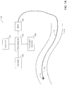
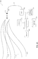
- Figure 1A is a schematic illustration of a system, generally referenced 100, for producing a mapping path of a trajectory of an MPS catheter, within a tubular organ of the body of a patient, constructed and operative in accordance with an embodiment of the disclosed technique.
- Figure 1B is a schematic illustration of a superimposition of the mapping path of the trajectory of the MPS catheter of Figure 1A , on an image of the tubular organ.
- System 100 includes a Medical Positioning System (MPS) 102, a processor 104, an imager 106, a pointing device 108, a display 110, an MPS catheter 112, an MPS sensor 114 and a memory (not shown).
- MPS sensor 114 is located at a distal portion 116 of MPS catheter 112 (i.e., typically attached thereto).
- MPS 102 includes an electromagnetic field generator (not shown) for generating an electromagnetic field (not shown). It is noted that MPS 102 typically employs a plurality of electromagnetic field generators (not shown).
- MPS 102 further includes an MPS processor (not shown).
- Processor 104 is coupled with MPS 102, imager 106, pointing device 108, display 110 and with the memory.
- MPS 102 is coupled with MPS sensor 114, via an electric conductor. Alternatively, MPS 102 is coupled with MPS sensor 114 via a wireless link.
- the MPS processor is coupled with the plurality of electromagnetic field generators and with MPS sensor 114.
- MPS sensor 114 is in form of a coil, which produces an output in response to the electromagnetic field generated by the electromagnetic field generator.
- MPS 102 is a device which determines the position of distal portion 116 of MPS catheter 112, according to the output of MPS sensor 114.
- the MPS processor determines the relative position of MPS sensor 114 from the plurality of electromagnetic field generators, according to the electromagnetic field that is generated by each respective electromagnetic field generator.
- Imager 106 acquires a pre-operative image 150 ( Figure 1B ), of a tubular organ 118 of the body of a patient (not shown).
- Imager 106 is a two-dimensional image acquisition device, such as a fluoroscope, an ultrasound image detector, a C-arm, and the like.
- imager 106 is a three-dimensional image acquisition device, such as computer tomography (CT) imager, magnetic resonance imager (MRI), positron emission tomography (PET) imager, single photon emission computer tomography (SPECT) imager, ultrasound image detector, infrared image detector, X-ray imager, optical coherence tomography (OCT) imager, intracardiac echocardiogram (ICE), and the like.
- Pointing device 108 is a registerer, employed for determining a registration situation, and is typically a user interface, which can be for example, a computer mouse, a touch screen, a track-ball, and the like.
- a three-dimensional coordinate system 126 ( Figure 1B ) associated with MPS 102 is registered with a two-dimensional coordinate system 156 associated with pre-operational image 150.
- a surgeon inserts MPS catheter 112 into tubular organ 118, until distal portion 114 of MPS catheter 112 enters a field of view (i.e., FOV) of imager 106.
- FOV field of view
- MPS 102 detects the position of distal portion 116 of MPS catheter 112, according to an output of MPS sensor 114.
- MPS 102 acquires a plurality of mapping positions 120 ( Figure 1B ), respective of the positions of distal portion 116, during movement of MPS catheter 112 within tubular organ 118, toward a region of interest within the body of the patient.
- MPS 102 acquires mapping positions 120 during pull-back of MPS catheter 112, from the region of interest toward a point of entry (not shown) of MPS catheter 112 into tubular organ 118.
- MPS 102 registers each of mapping positions 120 with pre-operational image 150, such that each of mapping positions 120 is associated with a respective two-dimensional coordinate on pre-operational image 150.
- Processor 104 constructs a mapping path 122 (i.e., an MPS trace), which is an approximate representation of the trajectory of the movement of MPS catheter 112, within tubular organ 118.
- Processor 104 constructs mapping path 122, according to the coordinates of each of mapping positions 120.
- the memory stores mapping path 122.
- Origin 124 is a reference point, which can be for example, a point on mapping path 122, one of mapping positions 120, a physical point on the body of the patient (e.g., as marked by the surgeon), and the like.
- the surgeon selects origin 124 by employing pointing device 108.
- Processor 104 superimposes mapping path 122 on pre-operational image 150, thereby producing a superimposed pre-operational image 170.
- the registration between coordinate system 126 associated with MPS 102 and coordinate system 156 associated with pre-operational image 150 facilitates this superposition.
- Processor 104 directs display 110 to display superimposed pre-operational image 170.
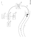
- Figure 2A is a schematic illustration of a system, generally referenced 200, for determining the position of a medical catheter, within a tubular organ of a patient, constructed and operative in accordance with another embodiment of the disclosed technique.
- Figure 2B is a schematic illustration of the mapping path of the trajectory of the MPS catheter of the system of Figure 1A , superimposed on an image of the tubular organ of the patient.
- System 200 includes a traveled length detector 202, a processor 204, an imager 206, a pointing device 208, a display 210, a medical catheter 212, a radiopaque marker 214, a memory (not shown), and an Intravascular Ultrasound (IVUS) imager 220.
- Radiopaque marker 214 and IVUS imager 220 are located at a distal portion 216 of medical catheter 212.
- Processor 204 is coupled with traveled length detector 202, imager 206, pointing device 208, display 210, and with the memory. Traveled length detector 202 is coupled with medical catheter 212.
- Processor 204, imager 206, pointing device 208, and display 210 are similar to processor 104, imager 106, pointing device 108, and display 110, respectively.
- processor 204, imager 206, pointing device 208, and display 210 are different than processor 104, imager 106, pointing device 108, and display 110, respectively.
- Traveled length detector 202 is a device which measures the travel distance of medical catheter 212, relative to a selected point. Traveled length detector 202 can be for example, a fiber-optic interferometric system, electromechanical system utilizing an electric generator, variable electro-resistive device (e.g., a linear potentiometer, rotary potentiometer), and the like.
- the surgeon inserts medical catheter 212 into tubular organ 218 (i.e., after MPS catheter 112 is removed from tubular organ 218), until radiopaque marker 214 of medical catheter 212 is located within the FOV of imager 206.
- the surgeon advances medical catheter 212 into tubular organ 118, and imager 206 acquires an operational image 250 of tubular organ 118, until radiopaque marker 214 reaches origin 124.
- Three-dimensional coordinate system 126 associated with MPS 102 is registered with a two-dimensional coordinate system 256 associated with operational image 250.
- three-dimensional coordinate system 126 is registered with a two-dimensional coordinate system (not shown) associated with imager 206.
- Processor 204 superimposes mapping path 122 on operational image 250, thereby producing a superimposed operational image 270.
- Processor 204 directs display 210 to display superimposed operational image 270.
- Radiopaque marker 214 is made of a material (e.g., barium sulfate, metal), which is opaque to an imaging medium employed by imager 206, such as sound waves, electromagnetic waves (e.g., X-ray), and the like. Therefore, radiopaque marker 214 is visible in operational image 250. The surgeon can observe an image 252 of radiopaque marker 214 within operational image 250, and within superimposed operational image 270.
- a material e.g., barium sulfate, metal
- an imaging medium employed by imager 206 such as sound waves, electromagnetic waves (e.g., X-ray), and the like. Therefore, radiopaque marker 214 is visible in operational image 250.
- the surgeon can observe an image 252 of radiopaque marker 214 within operational image 250, and within superimposed operational image 270.
- radiopaque marker 214 When radiopaque marker 214 reaches origin 124, the surgeon may input a reset command to processor 204, via pointing device 208, to reset a distance of travel (not shown) measured by traveled length detector 202.
- the surgeon advances medical catheter 212 within tubular organ 118, substantially along mapping path 122 toward a region of interest (not shown) of the body of the patient.
- Traveled length detector 202 measures and outputs the distance traveled by medical catheter 212, within tubular organ 118 relative to origin 124.
- processor 204 may correct the output (i.e., the distance measurement) of traveled length detector 202 whenever the path of medical catheter 212 deviates from the path of mapping path 122 (i.e., by fault of the surgeon or of other factors) by compensation methods known in the art.
- processor 204 estimates a current position of distal portion 216 within tubular organ 212, according to the output of traveled length detector 202, and according to calculated distances between mapping positions 120 ( Figure 1B ) from origin 124, along mapping path 122. Processor 204 superimposes a representation of previous positions 280, on superimposed operational image 270 and directs display 210 to display superimposed operational image 270.
- IVUS imager 220 acquires one or more images (not shown) of an inner wall (not shown) of tubular organ 118, during a forward movement of medical catheter 212 from the point of entry of medical catheter 212 into the body of the patient, toward the region of interest. Alternatively, IVUS imager 220 acquires the images during pull-back of medical catheter 212 from the region of interest, toward the point of entry of medical catheter 212 into the body of the patient.
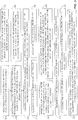
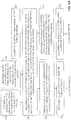
- FIG. 3 is a schematic illustration of a method for operating the systems of Figures 1A , 1B , 2A , and 2B , operative in accordance with a further embodiment of the disclosed technique.
- an MPS catheter is inserted into the tubular organ, the MPS catheter including an MPS sensor associated with an MPS.
- MPS catheter 112 is inserted into tubular organ 118.
- MPS catheter 112 includes an MPS sensor 114 at distal portion 116 of MPS catheter 112.
- MPS sensor 114 is associated with MPS 102.
- a pre-operational image of the tubular organ of the body of a patient is acquired by an imager.
- imager 106 acquires pre-operational image 150 of tubular organ 118.
- a plurality of mapping positions are acquired by the MPS, according to an output of the MPS sensor.
- MPS sensor 114 acquires mapping positions 120, respective of the respective position of distal portion 116.
- mapping position representations of the respective mapping positions are superimposed on the pre-operational image.
- processor 104 superimposes mapping positions 120 on operational image 150 (not shown), thereby producing superimposed operational image 170.
- a mapping path is constructed according to mapping positions, whereby a selected one of the mapping positions is defined as an initial position (i.e., an origin) of the mapping path.
- MPS 102 determines the position of each of mapping positions 120, and processor 104 constructs mapping path 112 of the trajectory of distal portion 116 of MPS catheter 112, within tubular organ 118.
- the surgeon determines the initial position 124 of mapping path 122 by employing pointing device 108.
- procedure 312 the MPS catheter is removed from the tubular organ.
- the surgeon removes MPS catheter 112 from tubular organ 118.
- procedure 314 an operational image of the tubular organ is acquired.
- imager 206 acquires operational image 250 of tubular organ 118. It is noted that in an intermediate procedure (not shown), which can follow procedure 314, the operational image 250 is registered with pre-operational image 150.
- procedure 316 a medical catheter is inserted into the tubular organ, until the selected portion of the medical catheter reaches the initial position.
- surgeon inserts medical catheter 212 into tubular organ 118, until the selected portion (e.g., marked by radiopaque marker 214) reaches initial position 124 by viewing image 252 of radiopaque marker 214 on superimposed operational image 270.
- a path representation of the mapping path, and an initial position representation of the initial position are displayed, superimposed on the operational image of the tubular organ, the operational image including a marker image of the tip of the medical catheter.
- display 210 displays superimposed operational image 270.
- Superimposed operation image 270 includes illustrates a path representation of mapping path 122, an initial position representation of initial position 124, and marker image 252 of radiopaque marker 214.
- the selected portion e.g., the tip
- the surgeon registers via pointing device 208 the selected portion (e.g., radiopaque marker 214) with initial position 124.
- the traveled length of the medical catheter within the tubular organ is measured from the initial position.
- traveled length detector 202 measures and outputs the traveled length of medical catheter 212 within tubular organ 118, relative to initial position 124.
- the current position of the selected portion of the medical catheter is estimated, according to the traveled length, the mapping positions, and according to the plurality of calculated distances between each of the mapping positions and the initial position along the mapping path.
- processor 204 determines an estimate of the current position of the selected portion (e.g., distal portion 216), according to the output of traveled length detector 202, and according to mapping positions 120 ( Figure 1B ).
- Processor 204 superimposes previous position 280 of distal portion 216, on superimposed operational image 270.
- Processor 204 directs display 210 to display superimposed operational image 270.
- the system further includes an organ monitor coupled with the processor.
- the organ monitor acquires an organ timing signal of an organ of the patient.
- the processor gates the image acquired by the imager (e.g., a real-time image, a cine-loop), with the respective organ timing signal of the organ.
- the display displays a representation of the current position as well as previous positions of a selected portion (e.g., the distal portion or the tip) of the medical catheter, on the respective operational image, associated with the respective organ timing signal.
- the surgeon can observe the representation of the tip of the medical catheter on an image of the tubular organ, which corresponds to the current position of the tip, respective of the current activity state of the organ.
- the organ monitor can monitor the timing signals of different organs of the body of the patient, which can cause the tubular organ in the respective organ such as the heart, lungs, and the like, to move in the corresponding cycles.
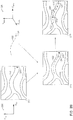
- Figure 4A is a schematic illustration of a system, generally referenced 400, for producing a multi-state mapping path of a trajectory of an MPS catheter, within a tubular organ of the body of a patient, constructed and operative in accordance with another embodiment of the disclosed technique.
- Figure 4B is a schematic illustration of an organ timing signal of an organ of a patient and representative points in the organ timing signal.
- Figure 4C is a schematic illustration of a superimposition of the multi-state mapping path of the trajectory of the MPS catheter of Figure 4A , on a plurality of pre-operational images.
- System 400 includes an MPS 402, a processor 404, an imager 406, a pointing device 408, a display 410, an MPS catheter 412, an MPS sensor 414, memory (not shown), and an organ monitor 430.
- MPS sensor 414 is located at a distal portion 416 of MPS catheter 412.
- Processor 404 is coupled with MPS 402, imager 406, pointing device 408, display 410, organ monitor 430, and with the memory.
- MPS 402 is coupled with MPS sensor 414, via an electric conductor. Alternatively, MPS 402 is coupled with MPS sensor 414, via a wireless link.
- Organ monitor 430 is a device which acquires an organ timing signal 440 ( Figure 4B ) of the organ of the patient (i.e., a signal representing the activity state of the organ, such as phases or states of the heart).
- Organ monitor 430 can be an electrocardiogram (ECG), a pulse monitor, a respiration monitor, and the like.
- Imager 406 acquires a plurality of pre-operational images 450 1 , 450 2 , and 450 N ( Figure 4C ) of a tubular organ 418.
- Each of pre-operational images 450 1 , 450 2 , and 450 N is associated with respective points 442 1 ( Figure 4B ), 442 2 , and 442 N in a cycle of organ timing signal 440.
- Pre-operational image 450 1 is associated with point 442 1 in the cycle of organ timing signal 440.
- Pre-operational image 450 2 is associated with point 442 2 in the cycle of organ timing signal 440.
- Pre-operational image 450 N is associated with point 440 N in the cycle of organ timing signal 440.
- imager 406 acquires a single real-time pre-operational image (not shown). It is noted that tubular organ 418 ( Figure 4A ) is depicted by multiple representations thereof, which represent the movement of tubular organ 418 during the various states of the organ cycle.
- a three-dimensional coordinate system 466 associated with MPS 402 is registered with a two-dimensional coordinate system 456 associated with each of pre-operational images 450 1 , 450 2 , and 450 N .
- three-dimensional coordinate system 466 is registered with a two-dimensional coordinate system (not shown) associated with imager 406.
- a surgeon inserts MPS catheter 412 into tubular organ 418, until distal portion 414 of MPS catheter 412 enters an FOV of imager 406.
- MPS 402 detects the position of MPS sensor 414, located substantially at a distal portion 416 of MPS catheter 412, according to an output of MPS sensor 414.
- MPS 402 acquires a plurality of mapping positions 460 1 , 460 2 , and 460 N ( Figure 4C ), respective of the position of distal portion 416, during a forward movement of MPS catheter 412, from the point of entry (not shown) of MPS catheter 412 toward the region of interest.
- MPS 402 acquires mapping positions 460 1 , 460 2 and 460 N during pull-back of MPS catheter 412, from the region of interest toward the point of entry.
- Mapping positions 460 1 , 460 2 and 460 N are classified into groups of mapping positions, each group of mapping positions being associated with a specific point in the cycle of the organ timing signal.
- a plurality of mapping positions 460 1 belong to a group 1 ( Figures 4B and 4C ) associated with point 442 1 in organ timing signal 440.
- a plurality of mapping positions 460 2 belong to a group 2 ( Figures 4B and 4C ) associated with point 442 2 in organ timing signal 440.
- a plurality of mapping positions 460 N belong to a group N ( Figures 4B and 4C ) associated with point 442 N in organ timing signal 440.
- Each mapping position in a particular group of mapping positions is acquired at the same point in the cycle of organ timing signal 440.
- each mapping position 460 1 is acquired at the same point 442 1 , in the cycle of organ timing signal 440, (i.e., once the cycle repeats, in a repetitive cyclic organ timing signal, the next mapping position is acquired).
- MPS 402 registers each mapping position in a particular group of mapping positions with respective two-dimensional coordinates in the respective pre-operational image. For example, MPS 402 registers each mapping position of mapping positions 460 1 with respective two-dimensional coordinates in pre-operational image 450 1 .
- Mapping positions 460 1 , 460 2 , and 460 N define a multi-state mapping path similar to mapping path 122 ( Figure 2B ). Each group of mapping positions defines a mapping path of the multi-state mapping path, corresponding to the respective point in the organ timing signal of the organ.
- Processor 402 produces a mapping path 462 1 from mapping positions 460 1 .
- Mapping path 462 1 is an approximate representation of the trajectory (not shown) of the movement of distal portion 416 of distal portion 416 of MPS catheter 412, within tubular organ 418, at point 442 1 in the cycle of organ timing signal 440.
- Processor 402 produces a mapping path 462 2 from mapping positions 460 2 .
- Mapping path 462 2 is an approximate representation of the trajectory (not shown) of the movement of distal portion 416 of MPS catheter 412, within tubular organ 418, at point 442 2 in the cycle of organ timing signal 440.
- Processor 402 produces a mapping path 462 N from mapping positions 460 N .
- Mapping path 462 N is an approximate representation of the trajectory (not shown) of the movement of distal portion 416 of MPS catheter 412, within tubular organ 418, at point 442 N in the cycle of organ timing signal 440.
- the memory stores mapping paths 462 1 , 462 2 , and 462 N .
- the surgeon determines a single initial position (not shown) of all of mapping paths 462 1 , 462 2 , and 462 N , typically one of mapping positions 460 1 , 460 2 , and 460 N , or alternatively, a physical point on the body of the patient, and the like. Further alternatively, the surgeon can determine a plurality of origins 464 1 , 464 2 , and 464 N ( Figure 4C ) of the respective mapping paths 462 1 , 462 2 , and 462 N .
- Each of origins 464 1 , 464 2 , and 464 N are reference points, which can be for example, points on respective mapping paths 462 1 , 462 2 , and 462 N , one of respective mapping positions 460 1 , 460 2 , and 460 N , a physical point on the body of the patient (e.g., marked by the surgeon), and the like.
- Each origin 464 1 , 464 2 and 464 N is associated with the respective point in the cycle of organ timing signal 440.
- origin 464 1 is associated with point 442 1 within the cycle of organ timing signal 440.
- each origin 464 1 , 464 2 , and 464 N is associated, respectively, with mapping paths 462 1 , 462 2 , and 462 N .
- the surgeon selects the initial position, or alternatively, origins 464 1 , 464 2 , and 464 N , by employing pointing device 408 ( Figure 4A ).
- Processor 404 superimposes mapping path 462 1 on pre-operational image 450 1 , thereby producing a superimposed pre-operational image 470 1 .
- Processor 404 superimposes mapping path 462 2 on pre-operational image 450 2 , thereby producing a superimposed pre-operational image 470 2 .
- Processor 404 superimposes mapping path 462 N on pre-operational image 450 N , thereby producing a superimposed pre-operational image 470 N .
- Display 410 displays superimposed pre-operational images 470 1 , 470 2 , and 470 N .
- Superimposed pre-operational images 470 1 , 470 2 , and 470 N are synchronized (i.e., gated) with organ timing signal 440, and are displayed on display 410 at a display rate, which is substantially equal or greater than the cycle time of organ timing signal 440, unless imager 406 acquires all except one of pre-operational images 450 1 , 450 2 , and 450 N at some point in the phase of the organ which is aperiodic, due to abnormal rhythms of the organ (e.g., arrhythmia in the heart).
- Figure 5A is a schematic illustration of a system, generally referenced 500, for determining the position of the tip of a medical catheter, within a tubular organ of the body of a patient, constructed and operative in accordance with a further embodiment of the disclosed technique.
- Figure 5B is a schematic illustration of a multi-state mapping path of a trajectory of the MPS catheter of the system of Figure 5A , superimposed on an operational image of the tubular organ of the patient.
- System 500 includes a traveled length detector 502, a processor 504, an imager 506, a pointing device 508, a display 510, a medical catheter 512, a radiopaque marker 514, an IVUS imager 520, a memory (not shown), and an organ monitor 530. Radiopaque marker 514 and IVUS imager 520 are located substantially at a distal portion 516 of medical catheter 512.
- Processor 504 is coupled with traveled length detector 502, imager 506, pointing device 508, display 510, organ monitor 530, and with the memory. Traveled length detector 502 is coupled with medical catheter 512. Traveled length detector 502, processor 504, imager 506, pointing device 508, and display 510, are similar to traveled length detector 202 ( Figure 2A ), processor 404 ( Figure 4A ), imager 406, pointing device 408, and display 410, respectively.
- the surgeon inserts medical catheter 512 into tubular organ 418, until radiopaque marker 514 of medical catheter 512 is within the FOV of imager 506.
- the surgeon advances medical catheter 512 into tubular organ 418, and imager 506 acquires a plurality of operational images 550 1 , 550 2 , and 550 N ( Figure 5B ) until radiopaque marker 514 reaches the initial position.
- the initial position can be one of the mapping positions, an activity-state specific origin (i.e., one of origins 464 1 , 464 2 , and 464 N ), corresponding to one of points 442 1 , 442 2 , 442 N ( Figure 4B ), respectively, and the like.
- each of operational images 550 1 , 550 2 , and 550 N is a real-time image of tubular organ 418.
- each of operational images 550 1 , 550 2 , and 550 N can be an image which is previously acquired.
- Radiopaque marker 514 is made of a material that is visible in operational images 550 1 , 550 2 , and 550 N of tubular organ 418. The surgeon can observe images 552 1 , 552 2 , and 552 N of radiopaque marker 514, in operational images 550 1 , 550 2 , and 550 N ( Figure 5B ), respectively.
- Operational images 550 1 , 550 2 , and 550 N are associated with points 442 1 , 442 2 , and 442 N ( Figure 4B ), respectively, in a cycle of organ timing signal 440.
- Operational image 550 1 is associated with point 442 1 in a cycle of organ timing signal 440.
- Operational image 550 2 is associated with point 442 2 in the cycle of organ timing signal 440.
- Operational image 550 N is associated with point 442 N in the cycle of organ timing signal 440.
- a three-dimensional coordinate system 466 associated with MPS 402 is registered with a two-dimensional coordinate system 556 associated with operational images 550 1 , 550 2 , and 550 N .
- three-dimensional coordinate system 466 is registered with a two-dimensional coordinate system (not shown) associated with imager 506.
- Processor 504 superimposes each of mapping paths 462 1 , 462 2 , and 462 N on operational images 550 1 , 550 2 , and 550 N , respectively, thereby producing superimposed operational images 570 1 , 570 2 , and 570 N , respectively.
- processor 504 superimposes mapping path 462 1 on operational image 550 1 , thereby producing a superimposed operational image 570 1 .
- Processor 504 superimposes mapping path 462 2 on operational image 550 2 , thereby producing a superimposed operational image 570 2
- Processor 504 superimposes mapping path 462 N on operational image 550 N , thereby producing a superimposed operational image 570 N
- Display 510 displays superimposed operational images 570 1 , 570 2 , and 570 N .
- radiopaque marker 514 When radiopaque marker 514 reaches the initial position (i.e., an activity-state specific origin, such as one of origins 464 1 , 464 2 , and 464 N ), the surgeon inputs a reset command to processor 504, by employing pointing device 508, to reset a distance of travel (not shown) of traveled length detector 502.
- the surgeon advances medical catheter 512 within tubular organ 418 substantially along a superposition (or a combination) of mapping paths 462 1 , 462 2 , and 462 N toward the region of interest of the body of the patient.
- a combination of mapping paths is formed from mapping paths 462 1 , 462 2 , and 462 N corresponding to groups of points respective of points 442 1 , 442 2 , and 442 N , respectively, in organ timing signal 440.
- Traveled length detector 502 measures and outputs the travel of medical catheter 512 within tubular organ 418 relative to the initial position. It is noted, that processor 504 may correct the output (i.e., the distance measurement) of traveled length detector 502 whenever the path of medical catheter 512 deviates from the path of each MPS paths 462 1 , 462 2 , and 462 N (i.e., by fault of the surgeon or by other factors) by compensation methods known in the art.
- processor 504 estimates the current position (not shown), of distal portion 516 within tubular organ 512, according to the output of traveled length detector 502, and according to mapping positions 562 1 , 562 2 , and 562 N , respectively.
- Processor 504 superimposes a representation of each of previous positions 580 1 , 580 2 , and 580 N , on superimposed operational images 570 1 , 570 2 , and 570 N , respectively.
- Display 510 displays superimposed operational images 570 1 , 570 2 , and 570 N in a real-time sequenced manner.
- the processor 504 can direct display 510 to display a playback of superimposed operational images 570 1 , 570 2 , and 570 N .
- IVUS imager 520 acquires ultrasound images (not shown) of the region of interest, during a forward movement of medical catheter 512 from a point of entry of medical catheter 512 into the body of the patient toward the region of interest. Alternatively, IVUS imager 520 acquires the ultrasound images during pull-back of medical catheter 512 from region of interest toward the point of entry.
- Superimposed operational images 570 1 , 570 2 , and 570 N are synchronized (i.e., gated) with organ timing signal 440, and are displayed on display 510 at a display rate, which is substantially equal or greater than the cycle time of organ timing signal 440, unless the surgeon acquires all except one of operational images 550 1 , 550 2 , and 550 N at some point in the phase of the organ which is aperiodic (due to abnormal rhythms of the organ, e.g., arrhythmia in the heart).
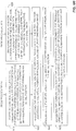
- Figure 6A is a schematic illustration of a method for operating the systems of Figures 4A , 4B , 4C 5A , and 5B , operative in accordance with another embodiment of the disclosed technique.
- Figure 6B is a schematic illustration of a continuation of the method of Figure 6A .
- a plurality of pre-operative images of a tubular organ of the body of a patient are acquired by an imager.
- imager 406 acquires pre-operational images 450 1 , 450 2 , and 450 N of tubular organ 418.
- imager 406 acquires a single real-time pre-operational image.
- organ timing signal of the tubular organ is acquired.
- organ monitor 530 ( Figure 5A ) is coupled (not shown) with tubular organ 418 and acquires organ timing signal 440 ( Figure 4B ) of tubular organ 418.
- the MPS catheter is inserted into the tubular organ, the MPS catheter including an MPS sensor coupled with an MPS.
- MPS catheter 412 is inserted into tubular organ 418.
- MPS catheter 412 includes MPS sensor 414, which is coupled with MPS 402.
- mapping positions within the tubular organ are acquired by the MPS according to an output of the MPS sensor.
- the mapping positions are grouped into a respective mapping position group, each mapping position group is associated with a respective point in the cycle of the organ timing signal.
- mapping positions 460 1 , 460 2 and 460 N are acquired by MPS 402 ( Figure 4A ) according to the output of MPS sensor 414 ( Figure 4A ).
- Mapping positions 460 1 , 460 2 and 460 N are grouped into respective mapping groups 442 1 , 442 2 and 442 N ( Figure 4B ), whereby each mapping position group 442 1 , 442 2 and 442 N is associated with a respective point (i.e., groups 1 through N illustrated in Figure 4B ) in the cycle of organ timing signal 440 ( Figure 4B ).
- mapping positions 460 1 , 460 2 and 460 N are displayed on display 410 ( Figure 4A ) each superimposed (not shown) on respective pre-operational images 470 1 , 470 2 and 470 N ( Figure 4C ).
- mapping paths are constructed, each of the mapping paths corresponding to a respective mapping position group.
- processor 404 constructs mapping paths 462 1 , 462 2 and 462 N ( Figure 4C ), each mapping path corresponding to a respective mapping position group (i.e., groups 1, 2, and N, respectively).
- procedure 614 the MPS catheter is removed from the tubular organ.
- the surgeon removes MPS catheter 412 from tubular organ 418.
- procedure 618 a medical catheter is inserted into the tubular organ until a selected portion of the medical catheter reaches a selected one of the mapping positions.
- the selected mapping position corresponds to a respective mapping position group, and is defined as an initial position.
- medical catheter 512 is inserted into tubular organ 418 until distal portion 516 (i.e., the selected portion) reaches one of mapping positions 460 1 , 460 2 and 460 N ( Figure 4C ).
- radiopaque marker 514 ( Figure 5A ), located at distal portion 516 ( Figure 5A ) reaches a respective one of origins 464 1 , 464 2 and 464 N ( Figure 4C ) of the respective group of mapping positions 460 1 , 460 2 and 460 N ( Figure 4C ).
- a selected mapping position is defined as the initial position (not shown). It is noted that that surgeon determines when radiopaque marker 514 reaches origin according to procedure 620.
- an initial position representation of the initial position, the plurality of mapping path representations of the mapping paths, and a plurality of marker images of the tip of the medical catheter are displayed, each superimposed on the respective operational image.
- representations of mapping paths 462 1 , 462 2 and 462 N are displayed by display 510 ( Figure 5A ), each respectively superimposed on operational images 550 1 , 550 2 and 550 N ( Figure 5B ) as superimposed operational images 570 1 , 570 2 and 570 N ( Figure 5B ), respectively.
- a representation of the initial position is superimposed (not shown) on superimposed operational images 570 1 , 570 2 and 570 N .
- Marker images 552 1 , 552 2 and 552 N ( Figure 5B ) of radiopaque marker 514 are each displayed on the respective one of superimposed operational images 570 1 , 570 2 and 570 N .
- each of operational images 550 1 , 550 2 , and 550 N of tubular organ 418 are registered with each of pre-operational images 450 1 , 450 2 , and 450 N , respectively.
- the selected portion of the medical catheter is registered with the initial position according to the initial position representation and the at least one marker image.
- the surgeon employs pointing device 508 ( Figure 5A ) for selecting a registration situation, thereby registering the selected portion (e.g., radiopaque marker 514) with the initial position, according to the initial position representation (e.g., a selected one of origins 464 1 , 464 2 and 464 N in Figure 5B ), according to the initial position representation and at least one marker image (i.e., one of marker images 552 1 , 552 2 and 552 N ).
- the initial position representation e.g., a selected one of origins 464 1 , 464 2 and 464 N in Figure 5B
- at least one marker image i.e., one of marker images 552 1 , 552 2 and 552 N .
- the traveled length of the medical catheter within the tubular organ is measured from the initial position.
- traveled length detector 502 measures the traveled length of medical catheter 512 within tubular organ 418 relative to the initial position, and produces an output respective of the traveled length.
- the current position of the selected portion of the medical catheter is estimated, according to the measured travel length relative to the origin, the mapping positions, and according to a plurality of calculated distances between each of the mapping positions within a respective mapping position group and the initial position.
- processor 504 estimates the current position of distal portion 516, according to the output of traveled length detector 502, and according to the mapping positions 460 1 , 460 2 , and 460 N ( Figure 4C ).
- Processor 504 superimposes previous positions 580 1 , 580 2 , and 580 N of distal portion 516 on operational images 550 1 , 550 2 , and 550 N , respectively, thereby producing superimposed operational images 570 1 , 570 2 , and 570 N , respectively.
- Display 510 displays superimposed operational images 570 1 , 570 2 , and 570 N in a real-time sequenced manner.
- the processor can direct display 510 to display a playback of superimposed operational images 570 1 , 570 2 , and 570 N .
Claims (4)
- Système pour déterminer la position d'une partie sélectionnée d'un cathéter médical (212) dans un organe tubulaire (118, 418) du corps d'un patient, le système comprenant :
un système de positionnement médical (MPS) (102, 402) comprenant :au moins un générateur de champ électromagnétique ;un cathéter MPS (112, 412) ;un capteur MPS (114, 414) situé au niveau d'une partie distale (116) du cathéter MPS (112, 412) ;un processeur MPS couplé audit au moins un générateur de champ électromagnétique et au capteur MPS (114, 414), le processeur MPS étant configuré pour déterminer la position relative du capteur MPS (114, 414) à partir dudit au moins un générateur de champ électromagnétique, dans lequel le système de positionnement médical (102, 402) est configuré pour acquérir une pluralité de positions de mappage (120) de la partie distale (116) du cathéter MPS (112, 412) pendant un mouvement du caractère MPS dans l'organe tubulaire (118, 418) ;le système comprenant en outre :un premier processeur (104) adapté pour construire un trajet de mappage (122) selon les coordonnées de la pluralité de positions de mappage (120), lequel trajet de mappage est une représentation approximative de la trajectoire du mouvement du cathéter MPS (112) à l'intérieur de l'organe tubulaire (118, 418) ;un imageur (106) pour acquérir une image pré-opérationnelle (150, 450) de l'organe tubulaire (118) lorsque le champ de vision de l'imageur (106) pour acquérir une image pré-opérationnelle (150, 450) comprend la partie distale (116) du cathéter MPS (112), dans lequel le processeur MPS est configuré pour enregistrer chacune des positions de mappage (120) avec l'image pré-opérationnelle (150, 450) de telle sorte que chacune des positions de mappage (120) est associée à une coordonnée bidimensionnelle respective sur l'image pré-opérationnelle (150) ;un premier dispositif de pointage (108) couplé au premier processeur (104, 404) et destiné à être utilisé par un utilisateur du système pour sélectionner une position initiale (124) sur le trajet de mappage (122) ;une mémoire couplée au premier processeur (104), la mémoire étant adaptée pour stocker le trajet de mappage (122) comprenant la position initiale (124) ; etun premier affichage (110) pour afficher une image pré-opérationnelle superposée (170) comprenant le trajet de mappage (122) superposé à l'image pré-opérationnelle (150, 450), dans lequel le premier processeur est configuré pour enregistrer un système de coordonnées tridimensionnel (126) associé au système de position médicale (102) avec un système de coordonnées bidimensionnel (156) associé à l'image pré-opérationnelle (150, 450), pour générer l'image pré-opérationnelle superposée (170), et pour diriger le premier affichage pour afficher l'image pré-opérationnelle superposée (170) ; le système comprenant en outre :le cathéter médical (212) ;un marqueur radio-opaque (214) situé au niveau de la partie sélectionnée (216) du cathéter médical (212) ;un imageur (206) pour acquérir une image opérationnelle (250) de l'organe tubulaire (118) ;un deuxième affichage (210) ;un second processeur (204) couplé à la mémoire et configuré pour enregistrer le système de coordonnées tridimensionnel (126) associé au système de positionnement médical (102) avec un système de coordonnées bidimensionnel (256) associé à l'imageur (206) pour acquérir une image opérationnelle (250), pour superposer le trajet de mappage (122) et la position initiale (124) sur l'image opérationnelle (250), produisant ainsi une image opérationnelle superposée (270), et pour diriger le second affichage (210) pour afficher l'image opérationnelle superposée (270) ;un second dispositif de pointage (208) couplé au second processeur et destiné à être utilisé par l'utilisateur du système pour faire coïncider le marqueur radio-opaque (214) avec la position initiale (124), lorsque le marqueur radio-opaque (214) atteint la position initiale (124) ; etun détecteur de longueur parcourue (202) couplé au cathéter médical (212) et adapté pour mesurer et délivrer une longueur parcourue du cathéter médical (212) à l'intérieur de l'organe tubulaire (118), la longueur parcourue étant définie comme la longueur parcourue par la partie sélectionnée du cathéter médical (212) à partir de la position initiale (124), dans lequelle second processeur (204) est couplé au détecteur de longueur parcourue (202) et est configuré pour estimer la position actuelle de la partie sélectionnée du cathéter médical (212) en fonction de la sortie du détecteur de longueur parcourue (202) et en fonction des distances calculées entre les positions de mappage (120) à partir de la position initiale (124) le long du trajet de mappage (122) ;dans lequel le second processeur (204) est en outre adapté pour superposer la position actuelle estimée sur l'image opérationnelle (250) lors de la génération de l'image opérationnelle superposée (270). - Système selon la revendication 1, dans lequel l'imageur (106) pour acquérir une image pré-opérationnelle et/ou l'imageur (206) pour acquérir une image opérationnelle est sélectionné à partir d'une liste constituée de :fluoroscope ;ultrasons ;bras en C ;imageur de tomographie assisté par ordinateur (CT) ;imageur de résonance magnétique (MRI);imageur de tomographie par émission de positrons (PET) ;imageur de tomographie assisté par ordinateur à émission monophotonique (SPECT) ;détecteur d'images infrarouges ;imageur à rayons X ;imageur de tomographie par cohérence optique (OCT) ; etéchocardiographie intracardiaque (ICE).
- Système selon la revendication 1, comprenant en outre un moniteur d'organe (430) couplé au premier processeur (404), le moniteur d'organe étant configuré pour acquérir un signal de synchronisation d'organe (440) de l'organe tubulaire,
dans lequel l'imageur (106) pour acquérir une image pré-opérationnelle est configuré pour acquérir une pluralité d'images pré-opérationnelles de l'organe tubulaire et le premier processeur (404) est en outre configuré pour associer chacune des images pré-opérationnelles acquises (450) à un point respectif dans le signal de synchronisation de l'organe (440). - Système selon la revendication 3, dans lequel le premier processeur (404) est en outre configuré pour enregistrer chacune des positions de mappage avec des coordonnées bidimensionnelles respectives d'une image pré-opérationnelle respective (450).
Applications Claiming Priority (2)
| Application Number | Priority Date | Filing Date | Title |
|---|---|---|---|
| US11950208P | 2008-12-03 | 2008-12-03 | |
| PCT/US2009/066653 WO2010065786A1 (fr) | 2008-12-03 | 2009-12-03 | Système et procédé pour déterminer la position de la pointe d'un cathéter médical à l'intérieur du corps d'un patient |
Publications (3)
| Publication Number | Publication Date |
|---|---|
| EP2348982A1 EP2348982A1 (fr) | 2011-08-03 |
| EP2348982A4 EP2348982A4 (fr) | 2013-06-19 |
| EP2348982B1 true EP2348982B1 (fr) | 2020-03-25 |
Family
ID=42233618
Family Applications (1)
| Application Number | Title | Priority Date | Filing Date |
|---|---|---|---|
| EP09831148.3A Active EP2348982B1 (fr) | 2008-12-03 | 2009-12-03 | Système pour déterminer la position de la pointe d'un cathéter médical à l'intérieur du corps d'un patient |
Country Status (3)
| Country | Link |
|---|---|
| US (2) | US9775538B2 (fr) |
| EP (1) | EP2348982B1 (fr) |
| WO (1) | WO2010065786A1 (fr) |
Families Citing this family (110)
| Publication number | Priority date | Publication date | Assignee | Title |
|---|---|---|---|---|
| US9572519B2 (en) | 1999-05-18 | 2017-02-21 | Mediguide Ltd. | Method and apparatus for invasive device tracking using organ timing signal generated from MPS sensors |
| US7778688B2 (en) * | 1999-05-18 | 2010-08-17 | MediGuide, Ltd. | System and method for delivering a stent to a selected position within a lumen |
| US9833167B2 (en) | 1999-05-18 | 2017-12-05 | Mediguide Ltd. | Method and system for superimposing virtual anatomical landmarks on an image |
| US9717468B2 (en) * | 2006-01-10 | 2017-08-01 | Mediguide Ltd. | System and method for positioning an artificial heart valve at the position of a malfunctioning valve of a heart through a percutaneous route |
| US10716528B2 (en) | 2007-03-08 | 2020-07-21 | Sync-Rx, Ltd. | Automatic display of previously-acquired endoluminal images |
| US11197651B2 (en) | 2007-03-08 | 2021-12-14 | Sync-Rx, Ltd. | Identification and presentation of device-to-vessel relative motion |
| JP5639764B2 (ja) | 2007-03-08 | 2014-12-10 | シンク−アールエックス,リミティド | 運動する器官と共に使用するイメージング及びツール |
| US9375164B2 (en) | 2007-03-08 | 2016-06-28 | Sync-Rx, Ltd. | Co-use of endoluminal data and extraluminal imaging |
| US9968256B2 (en) | 2007-03-08 | 2018-05-15 | Sync-Rx Ltd. | Automatic identification of a tool |
| US8781193B2 (en) | 2007-03-08 | 2014-07-15 | Sync-Rx, Ltd. | Automatic quantitative vessel analysis |
| US9629571B2 (en) | 2007-03-08 | 2017-04-25 | Sync-Rx, Ltd. | Co-use of endoluminal data and extraluminal imaging |
| US11064964B2 (en) | 2007-03-08 | 2021-07-20 | Sync-Rx, Ltd | Determining a characteristic of a lumen by measuring velocity of a contrast agent |
| US11064903B2 (en) | 2008-11-18 | 2021-07-20 | Sync-Rx, Ltd | Apparatus and methods for mapping a sequence of images to a roadmap image |
| US9101286B2 (en) | 2008-11-18 | 2015-08-11 | Sync-Rx, Ltd. | Apparatus and methods for determining a dimension of a portion of a stack of endoluminal data points |
| US8855744B2 (en) | 2008-11-18 | 2014-10-07 | Sync-Rx, Ltd. | Displaying a device within an endoluminal image stack |
| US9095313B2 (en) | 2008-11-18 | 2015-08-04 | Sync-Rx, Ltd. | Accounting for non-uniform longitudinal motion during movement of an endoluminal imaging probe |
| US10362962B2 (en) | 2008-11-18 | 2019-07-30 | Synx-Rx, Ltd. | Accounting for skipped imaging locations during movement of an endoluminal imaging probe |
| US9974509B2 (en) | 2008-11-18 | 2018-05-22 | Sync-Rx Ltd. | Image super enhancement |
| US9144394B2 (en) * | 2008-11-18 | 2015-09-29 | Sync-Rx, Ltd. | Apparatus and methods for determining a plurality of local calibration factors for an image |
| EP2632384B1 (fr) | 2010-10-27 | 2017-06-14 | Koninklijke Philips N.V. | Imagerie adaptative et optimisation de fréquence d'image sur la base d'une détection de forme en temps réel d'instruments médicaux |
| CA3085777C (fr) * | 2010-11-08 | 2022-03-15 | Conavi Medical Inc. | Systemes et procedes pour ameliorer la visualisation lors d'interventions minimalement invasives |
| US9271678B2 (en) * | 2011-04-08 | 2016-03-01 | Siemens Aktiengesellschaft | Constrained registration for motion compensation in atrial fibrillation ablation procedures |
| US9026242B2 (en) | 2011-05-19 | 2015-05-05 | Taktia Llc | Automatically guided tools |
| EP2723231A4 (fr) | 2011-06-23 | 2015-02-25 | Sync Rx Ltd | Nettoyage d'arrière-plan luminal |
| US10249036B2 (en) * | 2012-02-22 | 2019-04-02 | Veran Medical Technologies, Inc. | Surgical catheter having side exiting medical instrument and related systems and methods for four dimensional soft tissue navigation |
| US10556356B2 (en) | 2012-04-26 | 2020-02-11 | Sharper Tools, Inc. | Systems and methods for performing a task on a material, or locating the position of a device relative to the surface of the material |
| EP2852319B1 (fr) * | 2012-05-21 | 2017-05-17 | Sync-RX, Ltd. | Co-utilisation de données endoluminales et d'imagerie extraluminale |
| CA2875346A1 (fr) | 2012-06-26 | 2014-01-03 | Sync-Rx, Ltd. | Traitement d'image lie au flux dans les organes luminaux |
| JP5595621B2 (ja) * | 2012-08-06 | 2014-09-24 | パナソニック株式会社 | カテーテル先端回転角度検出装置、及び、プログラム |
| JP6329953B2 (ja) * | 2012-10-09 | 2018-05-23 | コーニンクレッカ フィリップス エヌ ヴェKoninklijke Philips N.V. | カテーテルのためのx線撮像システム |
| US20140100550A1 (en) * | 2012-10-10 | 2014-04-10 | Christie Digital Systems Canada Inc. | Catheter discrimination and guidance system |
| US9846206B2 (en) | 2012-12-10 | 2017-12-19 | General Electric Company | Systems and methods for magnetic material imaging |
| EP2996557B1 (fr) * | 2013-03-11 | 2019-05-01 | Institut Hospitalo-Universitaire de Chirurgie Mini -Invasive Guidee Par l'Image | Relocalisation de site anatomique à l'aide d'une synchronisation de données double |
| US20140267330A1 (en) * | 2013-03-14 | 2014-09-18 | Volcano Corporation | Systems and methods for managing medical image data for multiple users |
| US9693820B2 (en) | 2013-03-15 | 2017-07-04 | St. Jude Medical, Atrial Fibrillation Division, Inc. | System for detecting catheter electrodes entering into and exiting from an introducer |
| US9702762B2 (en) | 2013-03-15 | 2017-07-11 | Lightlab Imaging, Inc. | Calibration and image processing devices, methods, and systems |
| JP6480938B2 (ja) * | 2013-09-06 | 2019-03-13 | コーニンクレッカ フィリップス エヌ ヴェKoninklijke Philips N.V. | ナビゲーションシステム |
| US10098565B2 (en) * | 2013-09-06 | 2018-10-16 | Covidien Lp | System and method for lung visualization using ultrasound |
| US9211083B2 (en) | 2013-09-12 | 2015-12-15 | General Electric Company | Systems and methods for magnetic material imaging |
| EP2873371B1 (fr) * | 2013-11-13 | 2022-12-21 | Pie Medical Imaging BV | Procédé et système permettant d'enregistrer des images intravasculaires |
| DE102014200326A1 (de) * | 2014-01-10 | 2015-07-16 | Siemens Aktiengesellschaft | Verfahren zum Unterstützen einer Navigation eines medizinischen Instruments |
| US10499813B2 (en) | 2014-09-12 | 2019-12-10 | Lightlab Imaging, Inc. | Methods, systems and apparatus for temporal calibration of an intravascular imaging system |
| EP3230848A1 (fr) * | 2014-12-10 | 2017-10-18 | Sparkbio S.R.L. | Système pour la capture et l'affichage combiné de signaux vidéo et analogiques provenant d'instruments et d'un équipement électro-médicaux |
| WO2016128839A1 (fr) * | 2015-02-13 | 2016-08-18 | St. Jude Medical International Holding S.A.R.L. | Amélioration de modèle 3d à base de suivi |
| US11020017B2 (en) | 2015-02-16 | 2021-06-01 | Biosense Webster (Israel) Ltd. | Angioplasty guidewire |
| US10722139B2 (en) | 2015-02-16 | 2020-07-28 | Biosense Webster (Israel) Ltd. | Navigation of an angioplasty guidewire |
| EP3062142B1 (fr) | 2015-02-26 | 2018-10-03 | Nokia Technologies OY | Appareil pour un dispositif d'affichage proche |
| US10568694B2 (en) * | 2015-04-22 | 2020-02-25 | General Electric Company | Method and system for performing a guided biopsy using digital tomosynthesis |
| JP2018520718A (ja) | 2015-05-12 | 2018-08-02 | ナヴィックス インターナショナル リミテッドNavix International Limited | 誘電特性分析による接触品質評価 |
| US10828106B2 (en) | 2015-05-12 | 2020-11-10 | Navix International Limited | Fiducial marking for image-electromagnetic field registration |
| RU2017140235A (ru) | 2015-05-12 | 2019-06-13 | Навикс Интернэшнл Лимитед | Оценка очагов поражения посредством анализа диэлектрических свойств |
| US10278616B2 (en) | 2015-05-12 | 2019-05-07 | Navix International Limited | Systems and methods for tracking an intrabody catheter |
| CN107530878B (zh) | 2015-05-13 | 2021-01-08 | 整形工具股份有限公司 | 用于被引导工具的系统、方法和设备 |
| US10109058B2 (en) | 2015-05-17 | 2018-10-23 | Lightlab Imaging, Inc. | Intravascular imaging system interfaces and stent detection methods |
| US10222956B2 (en) | 2015-05-17 | 2019-03-05 | Lightlab Imaging, Inc. | Intravascular imaging user interface systems and methods |
| US9996921B2 (en) | 2015-05-17 | 2018-06-12 | LIGHTLAB IMAGING, lNC. | Detection of metal stent struts |
| US10646198B2 (en) | 2015-05-17 | 2020-05-12 | Lightlab Imaging, Inc. | Intravascular imaging and guide catheter detection methods and systems |
| EP3324830B1 (fr) | 2015-07-25 | 2023-01-04 | Lightlab Imaging, Inc. | Procédé et système de visualisation de données intravasculaires |
| EP3381014B1 (fr) | 2015-11-23 | 2020-12-16 | Lightlab Imaging, Inc. | Détection et validation d'ombres dans des images intravasculaires |
| US10244963B2 (en) | 2015-12-22 | 2019-04-02 | Biosense Webster (Israel) Ltd. | Ascertaining a position and orientation for visualizing a tool |
| US10524695B2 (en) | 2015-12-22 | 2020-01-07 | Biosense Webster (Israel) Ltd. | Registration between coordinate systems for visualizing a tool |
| CN116309390A (zh) | 2016-04-14 | 2023-06-23 | 光学实验室成像公司 | 血管分支的识别 |
| US10478254B2 (en) | 2016-05-16 | 2019-11-19 | Covidien Lp | System and method to access lung tissue |
| WO2017201026A1 (fr) | 2016-05-16 | 2017-11-23 | Lightlab Imaging, Inc. | Procédés et systèmes de détection et de diagnostic de stent absorbable intravasculaire |
| EP3484362A1 (fr) * | 2016-07-14 | 2019-05-22 | Navix International Limited | Navigation par cathéter à suivi caractéristique |
| US11537099B2 (en) | 2016-08-19 | 2022-12-27 | Sharper Tools, Inc. | Systems, methods and apparatus for sharing tool fabrication and design data |
| US10737070B2 (en) | 2016-10-11 | 2020-08-11 | St. Jude Medical, Cardiology Division, Inc. | Apparatus and method for navigating a medical device |
| WO2018092063A1 (fr) | 2016-11-16 | 2018-05-24 | Navix International Limited | Affichage en temps réel de changements de tissu liés au traitement à l'aide d'un matériau virtuel |
| US11284813B2 (en) | 2016-11-16 | 2022-03-29 | Navix International Limited | Real-time display of tissue deformation by interactions with an intra-body probe |
| WO2018092070A1 (fr) | 2016-11-16 | 2018-05-24 | Navix International Limited | Détection de position de l'œsophage par cartographie électrique |
| CN110198680B (zh) | 2016-11-16 | 2022-09-13 | 纳维斯国际有限公司 | 消融有效性估计器 |
| WO2018092059A1 (fr) | 2016-11-16 | 2018-05-24 | Navix International Limited | Rendu visuel dynamique de modèle de tissu |
| US10650552B2 (en) | 2016-12-29 | 2020-05-12 | Magic Leap, Inc. | Systems and methods for augmented reality |
| EP3343267B1 (fr) | 2016-12-30 | 2024-01-24 | Magic Leap, Inc. | Appareil de découplage de lumière polychromatique, affichages proches de l' il le comprenant et procédé de découplage de lumière polychromatique |
| EP3420884A1 (fr) * | 2017-06-28 | 2019-01-02 | Koninklijke Philips N.V. | Dispositif médical invasif à connexion souple |
| US11317966B2 (en) * | 2017-07-19 | 2022-05-03 | Biosense Webster (Israel) Ltd. | Impedance-based position tracking performance using scattered interpolant |
| US10578870B2 (en) | 2017-07-26 | 2020-03-03 | Magic Leap, Inc. | Exit pupil expander |
| JP6953616B2 (ja) * | 2017-07-26 | 2021-10-27 | キヤノン ユーエスエイ, インコーポレイテッドCanon U.S.A., Inc | 複数イメージングモダリティを相互レジストレーション及び表示するための方法 |
| CN107296645B (zh) * | 2017-08-03 | 2020-04-14 | 东北大学 | 肺穿刺手术最优路径规划方法及肺穿刺手术导航系统 |
| WO2019113570A1 (fr) | 2017-12-10 | 2019-06-13 | Magic Leap, Inc. | Revêtements antireflet sur guides d'ondes optiques |
| EP3729172A4 (fr) | 2017-12-20 | 2021-02-24 | Magic Leap, Inc. | Insert pour dispositif de visualisation à réalité augmentée |
| WO2019178567A1 (fr) | 2018-03-15 | 2019-09-19 | Magic Leap, Inc. | Correction d'image due à la déformation de composants d'un dispositif de visualisation |
| US11204491B2 (en) | 2018-05-30 | 2021-12-21 | Magic Leap, Inc. | Compact variable focus configurations |
| EP3803450A4 (fr) | 2018-05-31 | 2021-08-18 | Magic Leap, Inc. | Localisation de posture de tête par radar |
| CN112400157A (zh) | 2018-06-05 | 2021-02-23 | 奇跃公司 | 观看系统的基于单应性变换矩阵的温度校准 |
| US11092812B2 (en) | 2018-06-08 | 2021-08-17 | Magic Leap, Inc. | Augmented reality viewer with automated surface selection placement and content orientation placement |
| US11579441B2 (en) | 2018-07-02 | 2023-02-14 | Magic Leap, Inc. | Pixel intensity modulation using modifying gain values |
| WO2020010226A1 (fr) | 2018-07-03 | 2020-01-09 | Magic Leap, Inc. | Systèmes et procédés pour des applications de réalité virtuelle et de réalité augmentée |
| US11856479B2 (en) | 2018-07-03 | 2023-12-26 | Magic Leap, Inc. | Systems and methods for virtual and augmented reality along a route with markers |
| EP4270016A3 (fr) | 2018-07-24 | 2024-02-07 | Magic Leap, Inc. | Étalonnage dépendant de la température de dispositifs de détection de mouvement |
| WO2020023543A1 (fr) | 2018-07-24 | 2020-01-30 | Magic Leap, Inc. | Dispositif de visualisation à intégrant un joint anti-poussière |
| WO2020028834A1 (fr) | 2018-08-02 | 2020-02-06 | Magic Leap, Inc. | Système de visualisation avec compensation de distance interpupillaire basée sur le mouvement de la tête |
| EP3830631A4 (fr) | 2018-08-03 | 2021-10-27 | Magic Leap, Inc. | Correction de dérive basée sur une pose non fusionnée d'une pose fusionnée d'un totem dans un système d'interaction d'utilisateur |
| US20210177370A1 (en) * | 2018-08-22 | 2021-06-17 | Magic Leap, Inc. | Patient viewing system |
| EP3628235A1 (fr) * | 2018-09-26 | 2020-04-01 | Koninklijke Philips N.V. | Imagerie intravasculaire par ultrasons |
| US11918423B2 (en) | 2018-10-30 | 2024-03-05 | Corindus, Inc. | System and method for navigating a device through a path to a target location |
| CN117111304A (zh) | 2018-11-16 | 2023-11-24 | 奇跃公司 | 用于保持图像清晰度的图像尺寸触发的澄清 |
| DE102018220758B4 (de) * | 2018-11-30 | 2023-02-16 | Siemens Healthcare Gmbh | Vorrichtung und Verfahren zum Steuern eines Röntgengeräts |
| JP2022519292A (ja) | 2019-02-06 | 2022-03-22 | マジック リープ, インコーポレイテッド | 複数のプロセッサによって発生される総熱を限定するための標的意図ベースのクロック速度の決定および調節 |
| US11642172B2 (en) * | 2019-03-05 | 2023-05-09 | Biosense Webster (Israel) Ltd. | Showing catheter in brain |
| EP3939030A4 (fr) | 2019-03-12 | 2022-11-30 | Magic Leap, Inc. | Enregistrement d'un contenu local entre des premier et second visualiseurs de réalité augmentée |
| US11806094B2 (en) * | 2019-04-03 | 2023-11-07 | Biosense Webster (Israel) Ltd. | Catheter motion trace visualization |
| US11445232B2 (en) | 2019-05-01 | 2022-09-13 | Magic Leap, Inc. | Content provisioning system and method |
| CN114174895A (zh) | 2019-07-26 | 2022-03-11 | 奇跃公司 | 用于增强现实的系统和方法 |
| JP2023502927A (ja) | 2019-11-15 | 2023-01-26 | マジック リープ, インコーポレイテッド | 外科手術環境において使用するための視認システム |
| DE102020204574A1 (de) * | 2020-04-09 | 2021-10-14 | Siemens Healthcare Gmbh | Bildgebung eines robotisch bewegten medizinischen Objekts |
| CN215192193U (zh) * | 2020-12-31 | 2021-12-17 | 杭州堃博生物科技有限公司 | 体内导航装置、体内导航系统与医疗处理系统 |
| EP4042924A1 (fr) * | 2021-02-12 | 2022-08-17 | Koninklijke Philips N.V. | Estimation de la position d'un dispositif d'intervention |
| TW202327686A (zh) * | 2021-11-04 | 2023-07-16 | 美商阿比奥梅德公司 | 用於遞送導管式血泵之無螢光系統及方法 |
| CN114041828B (zh) * | 2022-01-13 | 2022-04-29 | 深圳瀚维智能医疗科技有限公司 | 超声扫查控制方法、机器人及存储介质 |
Family Cites Families (10)
| Publication number | Priority date | Publication date | Assignee | Title |
|---|---|---|---|---|
| GB2335744A (en) | 1998-03-27 | 1999-09-29 | Intravascular Res Ltd | Medical ultrasonic imaging |
| US6275124B1 (en) * | 1998-07-24 | 2001-08-14 | Lucent Technologies Inc. | Delay line filter having a single cross-coupled pair of elements |
| US8442618B2 (en) * | 1999-05-18 | 2013-05-14 | Mediguide Ltd. | Method and system for delivering a medical device to a selected position within a lumen |
| US7343195B2 (en) * | 1999-05-18 | 2008-03-11 | Mediguide Ltd. | Method and apparatus for real time quantitative three-dimensional image reconstruction of a moving organ and intra-body navigation |
| CA2436166A1 (fr) | 2001-02-06 | 2002-08-15 | Joshua Makower | Procedes et appareils pour des interventions transluminales guidees mettant en oeuvre des catheters penetrant la paroi arterielle et d'autres appareils |
| US20030220557A1 (en) | 2002-03-01 | 2003-11-27 | Kevin Cleary | Image guided liver interventions based on magnetic tracking of internal organ motion |
| DE10219594A1 (de) * | 2002-05-02 | 2003-11-13 | Philips Intellectual Property | Verfahren zur transkutanen Katheterführung |
| US20080262473A1 (en) * | 2004-10-19 | 2008-10-23 | Navotek Medical Ltd. | Locating a Catheter Tip Using a Tracked Guide |
| EP2086415B1 (fr) | 2006-11-22 | 2011-06-08 | Koninklijke Philips Electronics N.V. | Combinaison de données radiologigues avec des données acquises de manière intravasculaire |
| WO2009119691A1 (fr) | 2008-03-25 | 2009-10-01 | 株式会社 東芝 | Processeur d'image médicale et appareil de diagnostic à rayons x |
-
2009
- 2009-12-03 WO PCT/US2009/066653 patent/WO2010065786A1/fr active Application Filing
- 2009-12-03 EP EP09831148.3A patent/EP2348982B1/fr active Active
- 2009-12-03 US US13/130,377 patent/US9775538B2/en not_active Expired - Fee Related
-
2017
- 2017-08-29 US US15/689,950 patent/US20180070855A1/en not_active Abandoned
Non-Patent Citations (1)
| Title |
|---|
| None * |
Also Published As
| Publication number | Publication date |
|---|---|
| WO2010065786A1 (fr) | 2010-06-10 |
| US9775538B2 (en) | 2017-10-03 |
| US20110230758A1 (en) | 2011-09-22 |
| EP2348982A4 (fr) | 2013-06-19 |
| EP2348982A1 (fr) | 2011-08-03 |
| US20180070855A1 (en) | 2018-03-15 |
Similar Documents
| Publication | Publication Date | Title |
|---|---|---|
| EP2348982B1 (fr) | Système pour déterminer la position de la pointe d'un cathéter médical à l'intérieur du corps d'un patient | |
| JP4226904B2 (ja) | 医療用撮像兼ナビゲーションシステム | |
| CA2559340C (fr) | Procede et systeme pour presenter un dispositif medical a l'interieur d'une lumiere l'interieur d'une cavite | |
| EP3236854B1 (fr) | Amélioration de modèle 3d à base de suivi | |
| JP6099562B2 (ja) | 管腔内データおよび管腔外画像化の併用 | |
| JP4701179B2 (ja) | カテーテルをナビゲートするナビゲーションシステム | |
| US9811939B2 (en) | Method and system for registering intravascular images | |
| EP1720038B1 (fr) | Superposition de données ultrasonographiques avec une image pré-acquise | |
| JP5142719B2 (ja) | 内腔内の選択された位置へ医療用デバイスを移送するための方法およびシステム | |
| US7406346B2 (en) | Optical coherence tomography system for the examination of human or animal tissue or organs | |
| JP5161118B2 (ja) | 動脈の画像システム | |
| US20070055142A1 (en) | Method and apparatus for image guided position tracking during percutaneous procedures | |
| EP2470074B1 (fr) | Estimation de forme d'instrument | |
| JP2015519957A (ja) | 管腔内データと管腔外イメージングとの併用 | |
| MXPA06004653A (es) | Registro de mapa electroanatomico con imagen pre-adquirida usando ultrasonido. | |
| US8467850B2 (en) | System and method to determine the position of a medical instrument | |
| AU2012258444B2 (en) | Display of two-dimensional ultrasound fan |
Legal Events
| Date | Code | Title | Description |
|---|---|---|---|
| PUAI | Public reference made under article 153(3) epc to a published international application that has entered the european phase |
Free format text: ORIGINAL CODE: 0009012 |
|
| 17P | Request for examination filed |
Effective date: 20110524 |
|
| AK | Designated contracting states |
Kind code of ref document: A1 Designated state(s): AT BE BG CH CY CZ DE DK EE ES FI FR GB GR HR HU IE IS IT LI LT LU LV MC MK MT NL NO PL PT RO SE SI SK SM TR |
|
| DAX | Request for extension of the european patent (deleted) | ||
| A4 | Supplementary search report drawn up and despatched |
Effective date: 20130523 |
|
| RIC1 | Information provided on ipc code assigned before grant |
Ipc: A61B 19/00 20060101ALI20130516BHEP Ipc: A61B 5/05 20060101AFI20130516BHEP Ipc: A61B 5/00 20060101ALI20130516BHEP Ipc: A61B 8/00 20060101ALI20130516BHEP Ipc: A61B 6/00 20060101ALI20130516BHEP Ipc: A61M 25/00 20060101ALI20130516BHEP Ipc: A61B 8/12 20060101ALI20130516BHEP Ipc: A61B 8/08 20060101ALI20130516BHEP |
|
| 17Q | First examination report despatched |
Effective date: 20160610 |
|
| STAA | Information on the status of an ep patent application or granted ep patent |
Free format text: STATUS: EXAMINATION IS IN PROGRESS |
|
| REG | Reference to a national code |
Ref country code: DE Ref legal event code: R079 Ref document number: 602009061561 Country of ref document: DE Free format text: PREVIOUS MAIN CLASS: A61B0005050000 Ipc: A61B0005060000 |
|
| RIC1 | Information provided on ipc code assigned before grant |
Ipc: A61B 34/20 20160101ALI20171205BHEP Ipc: A61B 8/12 20060101ALI20171205BHEP Ipc: A61B 8/00 20060101ALI20171205BHEP Ipc: A61B 5/06 20060101AFI20171205BHEP |
|
| GRAP | Despatch of communication of intention to grant a patent |
Free format text: ORIGINAL CODE: EPIDOSNIGR1 |
|
| STAA | Information on the status of an ep patent application or granted ep patent |
Free format text: STATUS: GRANT OF PATENT IS INTENDED |
|
| INTG | Intention to grant announced |
Effective date: 20180125 |
|
| GRAJ | Information related to disapproval of communication of intention to grant by the applicant or resumption of examination proceedings by the epo deleted |
Free format text: ORIGINAL CODE: EPIDOSDIGR1 |
|
| STAA | Information on the status of an ep patent application or granted ep patent |
Free format text: STATUS: EXAMINATION IS IN PROGRESS |
|
| INTC | Intention to grant announced (deleted) | ||
| RIC1 | Information provided on ipc code assigned before grant |
Ipc: A61B 8/00 20060101ALI20171205BHEP Ipc: A61B 5/06 20060101AFI20171205BHEP Ipc: A61B 8/12 20060101ALI20171205BHEP Ipc: A61B 34/20 20160101ALI20171205BHEP |
|
| RAP1 | Party data changed (applicant data changed or rights of an application transferred) |
Owner name: ST. JUDE MEDICAL INTERNATIONAL HOLDING S.A R.L. Owner name: ST. JUDE MEDICAL, ATRIAL FIBRILLATION DIVISION, IN |
|
| GRAP | Despatch of communication of intention to grant a patent |
Free format text: ORIGINAL CODE: EPIDOSNIGR1 |
|
| STAA | Information on the status of an ep patent application or granted ep patent |
Free format text: STATUS: GRANT OF PATENT IS INTENDED |
|
| INTG | Intention to grant announced |
Effective date: 20191014 |
|
| GRAS | Grant fee paid |
Free format text: ORIGINAL CODE: EPIDOSNIGR3 |
|
| GRAA | (expected) grant |
Free format text: ORIGINAL CODE: 0009210 |
|
| STAA | Information on the status of an ep patent application or granted ep patent |
Free format text: STATUS: THE PATENT HAS BEEN GRANTED |
|
| AK | Designated contracting states |
Kind code of ref document: B1 Designated state(s): AT BE BG CH CY CZ DE DK EE ES FI FR GB GR HR HU IE IS IT LI LT LU LV MC MK MT NL NO PL PT RO SE SI SK SM TR |
|
| REG | Reference to a national code |
Ref country code: GB Ref legal event code: FG4D |
|
| REG | Reference to a national code |
Ref country code: DE Ref legal event code: R096 Ref document number: 602009061561 Country of ref document: DE |
|
| REG | Reference to a national code |
Ref country code: AT Ref legal event code: REF Ref document number: 1247594 Country of ref document: AT Kind code of ref document: T Effective date: 20200415 Ref country code: IE Ref legal event code: FG4D |
|
| PG25 | Lapsed in a contracting state [announced via postgrant information from national office to epo] |
Ref country code: NO Free format text: LAPSE BECAUSE OF FAILURE TO SUBMIT A TRANSLATION OF THE DESCRIPTION OR TO PAY THE FEE WITHIN THE PRESCRIBED TIME-LIMIT Effective date: 20200625 Ref country code: FI Free format text: LAPSE BECAUSE OF FAILURE TO SUBMIT A TRANSLATION OF THE DESCRIPTION OR TO PAY THE FEE WITHIN THE PRESCRIBED TIME-LIMIT Effective date: 20200325 |
|
| PG25 | Lapsed in a contracting state [announced via postgrant information from national office to epo] |
Ref country code: HR Free format text: LAPSE BECAUSE OF FAILURE TO SUBMIT A TRANSLATION OF THE DESCRIPTION OR TO PAY THE FEE WITHIN THE PRESCRIBED TIME-LIMIT Effective date: 20200325 Ref country code: GR Free format text: LAPSE BECAUSE OF FAILURE TO SUBMIT A TRANSLATION OF THE DESCRIPTION OR TO PAY THE FEE WITHIN THE PRESCRIBED TIME-LIMIT Effective date: 20200626 Ref country code: BG Free format text: LAPSE BECAUSE OF FAILURE TO SUBMIT A TRANSLATION OF THE DESCRIPTION OR TO PAY THE FEE WITHIN THE PRESCRIBED TIME-LIMIT Effective date: 20200625 Ref country code: SE Free format text: LAPSE BECAUSE OF FAILURE TO SUBMIT A TRANSLATION OF THE DESCRIPTION OR TO PAY THE FEE WITHIN THE PRESCRIBED TIME-LIMIT Effective date: 20200325 Ref country code: LV Free format text: LAPSE BECAUSE OF FAILURE TO SUBMIT A TRANSLATION OF THE DESCRIPTION OR TO PAY THE FEE WITHIN THE PRESCRIBED TIME-LIMIT Effective date: 20200325 |
|
| REG | Reference to a national code |
Ref country code: NL Ref legal event code: MP Effective date: 20200325 |
|
| REG | Reference to a national code |
Ref country code: LT Ref legal event code: MG4D |
|
| PG25 | Lapsed in a contracting state [announced via postgrant information from national office to epo] |
Ref country code: NL Free format text: LAPSE BECAUSE OF FAILURE TO SUBMIT A TRANSLATION OF THE DESCRIPTION OR TO PAY THE FEE WITHIN THE PRESCRIBED TIME-LIMIT Effective date: 20200325 |
|
| PG25 | Lapsed in a contracting state [announced via postgrant information from national office to epo] |
Ref country code: RO Free format text: LAPSE BECAUSE OF FAILURE TO SUBMIT A TRANSLATION OF THE DESCRIPTION OR TO PAY THE FEE WITHIN THE PRESCRIBED TIME-LIMIT Effective date: 20200325 Ref country code: CZ Free format text: LAPSE BECAUSE OF FAILURE TO SUBMIT A TRANSLATION OF THE DESCRIPTION OR TO PAY THE FEE WITHIN THE PRESCRIBED TIME-LIMIT Effective date: 20200325 Ref country code: PT Free format text: LAPSE BECAUSE OF FAILURE TO SUBMIT A TRANSLATION OF THE DESCRIPTION OR TO PAY THE FEE WITHIN THE PRESCRIBED TIME-LIMIT Effective date: 20200818 Ref country code: IS Free format text: LAPSE BECAUSE OF FAILURE TO SUBMIT A TRANSLATION OF THE DESCRIPTION OR TO PAY THE FEE WITHIN THE PRESCRIBED TIME-LIMIT Effective date: 20200725 Ref country code: SK Free format text: LAPSE BECAUSE OF FAILURE TO SUBMIT A TRANSLATION OF THE DESCRIPTION OR TO PAY THE FEE WITHIN THE PRESCRIBED TIME-LIMIT Effective date: 20200325 Ref country code: EE Free format text: LAPSE BECAUSE OF FAILURE TO SUBMIT A TRANSLATION OF THE DESCRIPTION OR TO PAY THE FEE WITHIN THE PRESCRIBED TIME-LIMIT Effective date: 20200325 Ref country code: LT Free format text: LAPSE BECAUSE OF FAILURE TO SUBMIT A TRANSLATION OF THE DESCRIPTION OR TO PAY THE FEE WITHIN THE PRESCRIBED TIME-LIMIT Effective date: 20200325 Ref country code: SM Free format text: LAPSE BECAUSE OF FAILURE TO SUBMIT A TRANSLATION OF THE DESCRIPTION OR TO PAY THE FEE WITHIN THE PRESCRIBED TIME-LIMIT Effective date: 20200325 |
|
| REG | Reference to a national code |
Ref country code: AT Ref legal event code: MK05 Ref document number: 1247594 Country of ref document: AT Kind code of ref document: T Effective date: 20200325 |
|
| REG | Reference to a national code |
Ref country code: DE Ref legal event code: R097 Ref document number: 602009061561 Country of ref document: DE |
|
| PG25 | Lapsed in a contracting state [announced via postgrant information from national office to epo] |
Ref country code: AT Free format text: LAPSE BECAUSE OF FAILURE TO SUBMIT A TRANSLATION OF THE DESCRIPTION OR TO PAY THE FEE WITHIN THE PRESCRIBED TIME-LIMIT Effective date: 20200325 Ref country code: DK Free format text: LAPSE BECAUSE OF FAILURE TO SUBMIT A TRANSLATION OF THE DESCRIPTION OR TO PAY THE FEE WITHIN THE PRESCRIBED TIME-LIMIT Effective date: 20200325 Ref country code: ES Free format text: LAPSE BECAUSE OF FAILURE TO SUBMIT A TRANSLATION OF THE DESCRIPTION OR TO PAY THE FEE WITHIN THE PRESCRIBED TIME-LIMIT Effective date: 20200325 |
|
| PGFP | Annual fee paid to national office [announced via postgrant information from national office to epo] |
Ref country code: IT Payment date: 20201215 Year of fee payment: 12 Ref country code: FR Payment date: 20201119 Year of fee payment: 12 Ref country code: GB Payment date: 20201130 Year of fee payment: 12 |
|
| PLBE | No opposition filed within time limit |
Free format text: ORIGINAL CODE: 0009261 |
|
| STAA | Information on the status of an ep patent application or granted ep patent |
Free format text: STATUS: NO OPPOSITION FILED WITHIN TIME LIMIT |
|
| PG25 | Lapsed in a contracting state [announced via postgrant information from national office to epo] |
Ref country code: PL Free format text: LAPSE BECAUSE OF FAILURE TO SUBMIT A TRANSLATION OF THE DESCRIPTION OR TO PAY THE FEE WITHIN THE PRESCRIBED TIME-LIMIT Effective date: 20200325 |
|
| 26N | No opposition filed |
Effective date: 20210112 |
|
| PG25 | Lapsed in a contracting state [announced via postgrant information from national office to epo] |
Ref country code: SI Free format text: LAPSE BECAUSE OF FAILURE TO SUBMIT A TRANSLATION OF THE DESCRIPTION OR TO PAY THE FEE WITHIN THE PRESCRIBED TIME-LIMIT Effective date: 20200325 |
|
| REG | Reference to a national code |
Ref country code: CH Ref legal event code: PL |
|
| PG25 | Lapsed in a contracting state [announced via postgrant information from national office to epo] |
Ref country code: MC Free format text: LAPSE BECAUSE OF FAILURE TO SUBMIT A TRANSLATION OF THE DESCRIPTION OR TO PAY THE FEE WITHIN THE PRESCRIBED TIME-LIMIT Effective date: 20200325 |
|
| REG | Reference to a national code |
Ref country code: BE Ref legal event code: MM Effective date: 20201231 |
|
| PG25 | Lapsed in a contracting state [announced via postgrant information from national office to epo] |
Ref country code: IE Free format text: LAPSE BECAUSE OF NON-PAYMENT OF DUE FEES Effective date: 20201203 Ref country code: LU Free format text: LAPSE BECAUSE OF NON-PAYMENT OF DUE FEES Effective date: 20201203 |
|
| PG25 | Lapsed in a contracting state [announced via postgrant information from national office to epo] |
Ref country code: LI Free format text: LAPSE BECAUSE OF NON-PAYMENT OF DUE FEES Effective date: 20201231 Ref country code: CH Free format text: LAPSE BECAUSE OF NON-PAYMENT OF DUE FEES Effective date: 20201231 |
|
| PG25 | Lapsed in a contracting state [announced via postgrant information from national office to epo] |
Ref country code: TR Free format text: LAPSE BECAUSE OF FAILURE TO SUBMIT A TRANSLATION OF THE DESCRIPTION OR TO PAY THE FEE WITHIN THE PRESCRIBED TIME-LIMIT Effective date: 20200325 Ref country code: MT Free format text: LAPSE BECAUSE OF FAILURE TO SUBMIT A TRANSLATION OF THE DESCRIPTION OR TO PAY THE FEE WITHIN THE PRESCRIBED TIME-LIMIT Effective date: 20200325 Ref country code: CY Free format text: LAPSE BECAUSE OF FAILURE TO SUBMIT A TRANSLATION OF THE DESCRIPTION OR TO PAY THE FEE WITHIN THE PRESCRIBED TIME-LIMIT Effective date: 20200325 |
|
| PG25 | Lapsed in a contracting state [announced via postgrant information from national office to epo] |
Ref country code: MK Free format text: LAPSE BECAUSE OF FAILURE TO SUBMIT A TRANSLATION OF THE DESCRIPTION OR TO PAY THE FEE WITHIN THE PRESCRIBED TIME-LIMIT Effective date: 20200325 |
|
| PG25 | Lapsed in a contracting state [announced via postgrant information from national office to epo] |
Ref country code: BE Free format text: LAPSE BECAUSE OF NON-PAYMENT OF DUE FEES Effective date: 20201231 |
|
| GBPC | Gb: european patent ceased through non-payment of renewal fee |
Effective date: 20211203 |
|
| PG25 | Lapsed in a contracting state [announced via postgrant information from national office to epo] |
Ref country code: GB Free format text: LAPSE BECAUSE OF NON-PAYMENT OF DUE FEES Effective date: 20211203 |
|
| PG25 | Lapsed in a contracting state [announced via postgrant information from national office to epo] |
Ref country code: FR Free format text: LAPSE BECAUSE OF NON-PAYMENT OF DUE FEES Effective date: 20211231 |
|
| PG25 | Lapsed in a contracting state [announced via postgrant information from national office to epo] |
Ref country code: IT Free format text: LAPSE BECAUSE OF NON-PAYMENT OF DUE FEES Effective date: 20211203 |
|
| REG | Reference to a national code |
Ref country code: DE Ref legal event code: R081 Ref document number: 602009061561 Country of ref document: DE Owner name: ST. JUDE MEDICAL INTERNATIONAL HOLDING S.A.R.L, LU Free format text: FORMER OWNERS: ST. JUDE MEDICAL, ATRIAL FIBRILLATION DIVISION, INC., ST. PAUL, MINN., US; ST. JUDE MEDICAL INTERNATIONAL HOLDING S.A.R.L., LUXEMBOURG, LU |
|
| P01 | Opt-out of the competence of the unified patent court (upc) registered |
Effective date: 20230602 |
|
| REG | Reference to a national code |
Ref country code: DE Ref legal event code: R082 Ref document number: 602009061561 Country of ref document: DE Representative=s name: ALPSPITZ IP ALLGAYER UND PARTNER PATENTANWAELT, DE |
|
| PGFP | Annual fee paid to national office [announced via postgrant information from national office to epo] |
Ref country code: DE Payment date: 20231108 Year of fee payment: 15 |