EP2302964A1 - Control device, communication terminal, control method, and communication method - Google Patents
Control device, communication terminal, control method, and communication method Download PDFInfo
- Publication number
- EP2302964A1 EP2302964A1 EP09797672A EP09797672A EP2302964A1 EP 2302964 A1 EP2302964 A1 EP 2302964A1 EP 09797672 A EP09797672 A EP 09797672A EP 09797672 A EP09797672 A EP 09797672A EP 2302964 A1 EP2302964 A1 EP 2302964A1
- Authority
- EP
- European Patent Office
- Prior art keywords
- channel
- beacon packet
- active period
- changed
- communication terminal
- Prior art date
- Legal status (The legal status is an assumption and is not a legal conclusion. Google has not performed a legal analysis and makes no representation as to the accuracy of the status listed.)
- Granted
Links
Images


Classifications
-
- H—ELECTRICITY
- H04—ELECTRIC COMMUNICATION TECHNIQUE
- H04W—WIRELESS COMMUNICATION NETWORKS
- H04W72/00—Local resource management
- H04W72/50—Allocation or scheduling criteria for wireless resources
- H04W72/54—Allocation or scheduling criteria for wireless resources based on quality criteria
- H04W72/541—Allocation or scheduling criteria for wireless resources based on quality criteria using the level of interference
-
- H—ELECTRICITY
- H04—ELECTRIC COMMUNICATION TECHNIQUE
- H04W—WIRELESS COMMUNICATION NETWORKS
- H04W72/00—Local resource management
- H04W72/20—Control channels or signalling for resource management
- H04W72/23—Control channels or signalling for resource management in the downlink direction of a wireless link, i.e. towards a terminal
-
- H—ELECTRICITY
- H04—ELECTRIC COMMUNICATION TECHNIQUE
- H04W—WIRELESS COMMUNICATION NETWORKS
- H04W84/00—Network topologies
- H04W84/02—Hierarchically pre-organised networks, e.g. paging networks, cellular networks, WLAN [Wireless Local Area Network] or WLL [Wireless Local Loop]
- H04W84/10—Small scale networks; Flat hierarchical networks
Definitions
- the present invention relates to a control device, a communication terminal, a control method, and a communication method, which are used for a wireless communication system, and more particularly relates to a control device, a communication terminal, a control method, and a communication method, which avoid interference caused by a plurality of channels being used in a sensor network or a wireless communication network using an active RF (Radio Frequency) tag.
- RF Radio Frequency
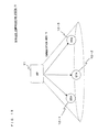
- FIG. 13 shows a conventional wireless communication system 10.
- the wireless communication system 10 includes a control device (AP: Access Point) 11, and first to third communication terminals (STA: Station) 12-1 to 12-3.
- the first to third communication terminals 12-1 to 12-3 exist within a communication area 15 of the control device 11.
- the control device 11 periodically broadcasts a beacon packet to the first to third communication terminals 12-1 to 12-3 which are all the communication terminals existing within the communication area 15.
- the beacon packet includes control information.
- the first to third communication terminals 12-1 to 12-3 receive the beacon packet from the control device 11, and communicate with the control device 11 based on the control information included in the beacon packet.
- CSMA Carrier Sense Multiple Access
- TDMA Time Division Multiple Access
- FDMA Frequency Division Multiple Access
- SDMA Space Division Multiple Access
- each of the communication terminals 12-1 to 12-3 is characterized by having a small size and low power consumption that allows the communication terminal to be driven by a battery for several years. Accordingly, in order to reduce power consumption of each of the communication terminals 12-1 to 12-3, a communication protocol and a frame format are devised. For example, a frame format including an active period in which each of the communication terminals 12-1 to 12-3 performs communication and an inactive period in which each of the communication terminals 12-1 to 12-3 does not perform communication is used.
- each of the communication terminals 12-1 to 12-3 does not perform communication and therefore can be in a sleep mode. That is, by setting the inactive period long, a time period in which each of the communication terminals 12-1 to 12-3 is in the sleep mode becomes long, and thus the power consumption can be reduced.
- FIG. 14 shows a conventional frame format 50.
- a frame 51 which is described in a frame format 50 includes an active period 52 and an inactive period 53.
- the active period 52 is a period in which each of the communication terminals 12-1 to 12-3 performs communication, and has a plurality of time slots.
- the plurality of time slots of the active period 52 are shared among all the communication terminals existing within the network of the wireless communication system 10.
- the first time slot is allocated as a period for transmitting and receiving a beacon packet 54.
- the control device 11 broadcasts the beacon packet 54 to the first to third communication terminals 12-1 to 12-3 which are all the communication terminals existing within the communication area 15.
- the beacon packet 54 includes control information concerning the frame 51, such as the number of time slots of the active period 52, allocation of the time slots, the length of the active period 52, the length of the inactive period 53, and a time until transmission of the next beacon packet.
- the time slots other than the first time slot are used for communication between the control device 11 and each of the communication terminals 12-1 to 12-3.
- the inactive period 53 is a period in which each of the communication terminals 12-1 to 12-3 does not perform communication. In the inactive period 53, each of the communication terminals 12-1 to 12-3 is in a sleep mode, and thereby the power consumption is reduced.
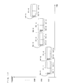
- FIG. 15 shows a communication sequence between the control device 11 and each of the communication terminals 12-1 to 12-3 in the wireless communication system 10.
- the third communication terminal 12-3 is omitted.
- the control device 11 broadcasts a beacon packet 54-1 to each of the communication terminals 12-1 and 12-2.
- Each of the communication terminals 12-1 and 12-2 receives the beacon packet 54-1 from the control device 11, and acquires control information included in the beacon packet 54-1.
- each of the communication terminals 12-1 and 12-2 communicates with each other.
- each of the communication terminals 12-1 and 12-2 transmits data to the control device 11, and, in response thereto, the control device 11 transmits response data to each of the communication terminals 12-1 and 12-2.
- an inactive period 53-1 the control device 11 and each of the communication terminals 12-1 and 12-2 do not communicate with each other.
- the control device 11 and each of the communication terminals 12-1 and 12-2 enter the sleep mode, and thereby power consumption can be reduced.
- the length of the inactive period 53-1 is preliminarily notified by the control information included in the beacon packet 54-1.
- the control device 11 and each of the communication terminals 12-1 and 12-2 recover from the sleep mode to an operation mode, and prepare for communication of a next frame.
- the control device 11 broadcasts the beacon packet 54-1 to each of the communication terminals 12-1 and 12-2. Then, by repeating the same process described above, the control device 11 and each of the communication terminals 12-1 and 12-2 communicate with each other.
- the control device 11 in the active period 52-2, communication from the first communication terminal 12-1 to the control device 11 fails. Although data is transmitted from the first communication terminal 12-1 to the control device 11, the control device 11 cannot properly receive the data transmitted from the first communication terminal 12-1. In this case, the control device 11 cannot transmit response data to the first communication terminal 12-1. Since no response data is transmitted from the control device 11 even when a predetermined time period elapses, the first communication terminal 12-1 determines that the communication fails. Then, the first communication terminal 12-1 re-transmits data to the control device 11. Here, it is assumed that the control device 11 can properly receive the data re-transmitted from the first communication terminal 12-1. In this case, in response to the re-transmitted data, the control device 11 transmits response data to the first communication terminal 12-1, and the communication successfully completes.
- FIG. 16 shows a channel band of a wireless channel.
- FIG. 16 shows a spectrum mask for channels CH1 to CH6, with the horizontal axis indicating a frequency.
- First to sixth channel bands 91 to 96 are channel bands of the channels CH1 to CH6, respectively.
- the control device 11 selects a channel to be used for communication, from the channels CH1 to CH6, and broadcasts a beacon packet to the first to third communication terminals 12-1 to 12-3 which are all the communication terminals existing within the communication area 15.
- Each of the communication terminals 12-1 to 12-3 performs channel scanning, and participates in a network of a channel through which a beacon packet is received. In this manner, communication between the control device 11 and each of the communication terminals 12-1 to 12-3, which exist in the communication area 15 managed by the control device 11, starts.
- a frequency band used by the network of the wireless communication system 10 described above is often shared with another network system. This causes a problem of interference between systems or between networks.
- a passive RF tag and an active RF tag partly use the same channel.
- more network systems such as a wireless LAN share a frequency band.
- a wireless terminal which uses a simple, small-size radio frequency component such as an active RF tag cannot obtain channel selectivity and thus may suffer from interference.
- FIG. 17 shows a situation in which the first communication terminal 12-1 changes a use channel by using the frame 51 which is described in the frame format 50 shown in FIG. 14 .
- communication of a frame 51-1 is performed using a channel CH1.
- the channel CH1 is largely influenced by interference from another network system.
- the control device 11 determines that communication with the first communication terminal 12-1 cannot be normally performed with the channel CH1, and transmits information for changing a use channel from the channel CH1 to a channel CH2 by using a beacon packet 54-2.
- the first communication terminal 12-1 receives the beacon packet 54-2 including information for changing the use channel from the channel CH1 to the channel CH2.
- the control device 11 and the first communication terminal 12-1 communicate with each other by using the channel CH1, and after the active period 52-2 ends, in an inactive period 53-2, the use channel is changed to the channel CH2.
- the control device 11 and the first communication terminal 12-1 communicate with each other by using the channel CH2.
- the use channel is further changed from the channel CH2 to a channel CH3.
- control device 11 selects a channel to be used for communication from the channels CH1 to CH6 so as to avoid the interference from the another network system, and causes each communication terminal within the network to change a use channel.
- Patent Literature 1 discloses a method of avoiding interference by performing communication using the channel CH2 in an inactive period, in a case where it is determined in an active period that the channel CH1 is largely influenced by interference from another network system.
- each communication terminal receives a beacon packet from a control device, only in a first time slot of an active period. Therefore, even if the communication terminal acquires information concerning a channel change, which is included in the received beacon packet, the communication terminal actually performs communication using the changed channel, from an active period of a next frame. That is, the control device and each communication terminal spend a long time before a channel is changed for avoiding interference from another network system and the control device and each communication terminal can actually communicate with each other by using the changed channel.
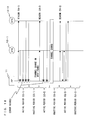
- FIG. 18 shows a communication sequence between the control device 11 and each of the communication terminals 12-1 to 12-3 in the wireless communication system 10.
- the third communication terminal 12-3 is omitted.
- the control device 11 broadcasts the beacon packet 54-1 to each of the communication terminals 12-1 and 12-2.
- Each of the communication terminals 12-1 and 12-2 receives the beacon packet 54-1 from the control device 11, and acquires control information included in the beacon packet 54-1.
- the control device 11 and each of the communication terminals 12-1 and 12-2 communicate with each other.
- a currently used channel is largely influenced by interference from another network system, and thus, in the active period 52-1, communication from each of the communication terminals 12-1 and 12-2 to the control device 11 fails.
- the control device 11 determines that communication with each of the communication terminals 12-1 and 12-2 cannot be normally performed with the currently used channel.
- control device 11 notifies the information to each of the communication terminals 12-1 and 12-2, in the next active period 52-2.
- the control device 11 and each of the communication terminals 12-1 and 12-2 do not communicate with each other.
- the control device 11 and each of the communication terminals 12-1 and 12-2 enter the sleep mode, and thereby power consumption can be reduced.
- the length of the inactive period 53-1 is preliminarily notified by the control information included in the beacon packet 54-1.
- the control device 11 and each of the communication terminals 12-1 and 12-2 recover from the sleep mode to the operation mode, and prepare for communication of a next frame.
- the control device 11 broadcasts the beacon packet 54-2 to each of the communication terminals 12-1 and 12-2.
- the beacon packet 54-2 includes information for changing a use channel, but in the active period 52-2, each of the communication terminals 12-1 and 12-2 performs communication by using the channel that has been used in the immediately preceding active period 52-1. Therefore, there is still large influence of interference from another network system, and communication from each of the communication terminals 12-1 and 12-2 to the control device 11 fails.
- the control device 11 and each of the communication terminals 12-1 and 12-2 perform a channel change process for changing the use channel to the channel notified in the beacon packet 54-2, and then enter the sleep mode.
- the control device 11 After the inactive period 53-2 ends, in the first time slot of an active period 52-3, the control device 11 broadcasts a beacon packet 54-3 to each of the communication terminals 12-1 and 12-2, by using the changed channel.
- control device 11 and each of the communication terminals 12-1 and 12-2 communicate with each other by using the changed channel, and thereby avoid interference from another network system.
- the same channel is used in the active period 52-2.
- each of the communication terminals 12-1 and 12-2 repeatedly performs re-transmission for the failure in the active period 52-1, congestion further increases.
- a possibility that communication packets collide with each other increases, and the congestion further increases.
- a beacon packet including the information for changing the use channel may be transmitted in the inactive period, so that a change of the use channel is completed before the next active period starts.
- each communication terminal cannot enter the sleep mode because the communication terminal performs communication in the inactive period. Thus, power consumption cannot be reduced.
- an object of the present invention is to unfailingly realize communication between a control device and a communication terminal by using a channel that is changed in a manner that: the control device selects a channel from a plurality of channels so as to avoid interference from another network system, when the control device determines that there is large influence of interference from another network system in communication with the communication terminal; and the control device causes the communication terminal within a network to change a use channel in a short time.
- a control device which manages a communication terminal within a communication area and communicates with the communication terminal in an active period by using a plurality of predetermined frequency channels, the control device comprising: a first beacon packet generation section that generates a first beacon packet which includes information indicating the active period and one or more candidate channels to which a use channel is possibly changed from a currently used channel; a first beacon packet transmission section that transmits the first beacon packet to the communication terminal, at the beginning of the active period; a second beacon packet generation section that: determines whether or not the use channel is to be changed, based on a state of communication with the communication terminal in the active period indicated by the transmitted first beacon packet; and generates a second beacon packet which includes information of whether or not the use channel is to be changed; a second beacon packet transmission section that transmits the second beacon packet to the communication terminal, at the end of the active period; and a channel change processing section that: when the second beacon packet generation section determines that the use channel is to be changed
- the second beacon packet generation section determines that the use channel is to be changed, the second beacon packet includes the change channel, and, when the second beacon packet generation section determines that the use channel is not to be changed, the second beacon packet includes one or more candidate channels to which the use channel is possibly changed from the currently used channel.
- the change channel is any of the one or more candidate channels included in the first beacon packet, or the change channel is a channel different from the one or more candidate channels included in the first beacon packet.
- the first beacon packet includes a plurality of candidate channels of which a priority order is defined.
- a communication terminal is a communication terminal which is managed by a control device of a communication area to which the communication terminal belongs, and communicates with the control device in an active period by using any of a plurality of predetermined frequency channels, the communication terminal comprising: a first beacon packet reception section that receives, from the control device, a first beacon packet which includes information indicating the active period and one or more candidate channels to which a use channel is possibly changed from a currently used channel, at the beginning of the active period; a second beacon packet reception section that receives, from the control device, a second beacon packet which includes information of whether or not the use channel is to be changed, at the end of the active period; and a channel change processing section that, based on the information of whether or not the use channel is to be changed which is included in the second beacon packet, when the use channel is to be changed, changes the use channel to a change channel different from the currently used channel after the active period ends and before a next active period starts, and, when the use channel is not to
- the second beacon packet when the use channel is to be changed, the second beacon packet includes the change channel, and, when the use channel is not to be changed, the second beacon packet includes one or more candidate channels to which the use channel is possibly changed from the currently used channel.
- the change channel is any of the one or more candidate channels included in the first beacon packet, or the change channel is a channel different from the one or more candidate channels included in the first beacon packet.
- the first beacon packet includes a plurality of candidate channels of which a priority order is defined.
- the channel change processing section changes the use channel to a change channel different from the currently used channel.
- the change channel is the one or more candidate channels included in the first beacon packet or the second beacon packet which has been previously successfully received.
- the channel change processing section changes the use channel to a change channel different from the currently used channel.
- the change channel is the one or more candidate channels included in the first beacon packet or the second beacon packet which has been previously successfully received.
- a wireless communication system includes the control device and the communication terminal described above.
- a control method is a control method performed by a control device which manages a communication terminal within a communication area and communicates with the communication terminal in an active period by using a plurality of predetermined frequency channels, the control method comprising: a first beacon packet generation step of generating a first beacon packet which includes information indicating the active period and one or more candidate channels to which a use channel is possibly changed from a currently used channel; a first beacon packet transmission step of transmitting the first beacon packet to the communication terminal at the beginning of the active period; a second beacon packet generation step of: determining whether or not the use channel is to be changed, based on a state of communication with the communication terminal in the active period indicated by the transmitted first beacon packet; and generating a second beacon packet which includes information of whether or not the use channel is to be changed; a second beacon packet transmission step of transmitting the second beacon packet to the communication terminal at the end of the active period; and a channel change processing step of: when the second beacon packet generation section determines that the use channel
- a communication method is a communication method performed by a communication terminal which is managed by a control device of a communication area to which the communication terminal belongs, and communicates with the control device in an active period by using any of a plurality of predetermined frequency channels, the communication method comprising: a first beacon packet reception step of receiving, from the control device, a first beacon packet which includes information indicating the active period and one or more candidate channels to which a use channel is possibly changed from a currently used channel, at the beginning of the active period; a second beacon packet reception step of receiving, from the control device, a second beacon packet which includes information of whether or not the use channel is to be changed, at the end of the active period; and a channel change processing step of, based on the information of whether or not the use channel is to be changed which is included in the second beacon packet, when the use channel is to be changed, changes the use channel to a change channel different from the currently used channel after the active period ends and before a next active period starts, and, when the use
- a sequence of steps of the control method and the communication method described above which are performed by the control device and the communication terminal, respectively, may be provided in the form of a program for causing a computer to perform the process steps.
- the program may be recorded on a computer-readable storage medium and, in such a mode, introduced into the computer.
- the control device determines that influence of interference from another network system is large in communication with the communication terminal, the control device selects a channel from a plurality of channels so as to avoid the interference from the another network system, and causes the communication terminal within the network to change the use channel in a short time. Thereby, communication between the control device and the communication terminal can be unfailingly realized by using the changed channel.
- FIG. 1A shows a wireless communication system 100 according to a first embodiment of the present invention.
- the wireless communication system 100 includes a control device (AP: Access Point) 110 and first to third communication terminals (STA: Station) 120-1 to 120-3.
- the first to third communication terminals 120-1 to 120-3 exist within a communication area 150 of the control device 110.
- the control device 110 periodically broadcasts a beacon packet to the first to third communication terminals 120-1 to 120-3 which are all the communication terminals existing within the communication area 150.
- the beacon packet includes control information.
- Each of the first to third communication terminals 120-1 to 120-3 receives the beacon packet from the control device 110, and communicates with the control device 110 based on the control information included in the beacon packet.
- a configuration of the wireless communication system 100 is basically the same as a configuration of the wireless communication system 10 shown in FIG. 13 .
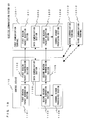
- FIG. 1B shows the control device 110 and the communication terminals 120-1 to 120-3, which form the wireless communication system 100 according to the first embodiment of the present invention.
- the control device 110 includes a first beacon packet generation section 1101, a first beacon packet transmission section 1102, a data communication section 1103, a second beacon packet generation section 1104, a second beacon packet transmission section 1105, and a channel change processing section 1106.
- the first communication terminal 120-1 includes a first beacon packet reception section 1201, a data communication section 1202, a second beacon packet reception section 1203, and a channel change processing section 1204.
- the first beacon packet transmission section 1102 of the control device 110 transmits, to the first communication terminal 120-1, a first beacon packet generated by the first beacon packet generation section 1101.
- the first beacon packet reception section 1201 of the first communication terminal 120-1 receives the first beacon packet from the control device 110. Then, based on the first beacon packet, the data communication section 1103 of the control device 110 and the data communication section 1202 of the first communication terminal 120-1 communicate with each other.
- the second beacon packet generation section 1104 of the control device 110 determines whether or not a use channel is to be changed from a currently used channel to another channel, based on a state of the communication between the control device 110 and the first communication terminal 120-1. Then, the second beacon packet generation section 1104 of the control device 110 generates a second beacon packet which includes information of whether or not the use channel is to be changed.
- the second beacon packet transmission section 1105 of the control device 110 transmits, to the first communication terminal 120-1, the second beacon packet generated by the second beacon packet generation section 1104.
- the second beacon packet reception section 1203 of the first communication terminal 120-1 receives the second beacon packet from the control device 110.
- the channel change processing section 1204 of the first communication terminal 120-1 changes the use channel based on the information of whether or not the use channel is to be changed, which is included in the second beacon packet.
- the channel change processing section 1106 of the control device 110 changes the use channel, based on the determination, which has been performed by the second beacon packet generation section 1104, of whether or not the use channel is to be changed.
- FIG. 2 shows the communication terminals 120-1 to 120-3.
- each of the communication terminals 120-1 to 120-3 includes a control section 121, a memory 122, a modulation section 123, a demodulation section 124, a radio frequency section 125, and an antenna 126.
- the control section 121 processes transmission data and reception data, based on an operation state of each of the communication terminals 120-1 to 120-3, which is held in the memory 122.
- the control section 121 generates the transmission data.
- the modulation section 123 converts the transmission data generated by the control section 121, into a transmission signal.
- the radio frequency section 125 converts the transmission signal resulting from the conversion performed by the modulation section 123, into a wireless signal, and transmits the wireless signal through the antenna 126.
- the wireless signal received by the antenna 126 is converted into a reception signal by the radio frequency section 125.
- the demodulation section 124 converts the reception signal resulting from the conversion performed by the radio frequency section 125, into reception data, and outputs the reception data to the control section 121.
- FIG. 3 shows a hardware block diagram of the modulation section 123, the demodulation section 124, and the radio frequency section 125, which are shown in FIG. 2 .
- the modulation section 123 includes an encoding section 131 and a digital modulation section 132
- the demodulation section 124 includes a decoding section 133 and a digital demodulation section 134.
- the radio frequency section 125 includes a digital-analog conversion section (DAC) 135, a low pass filter (LPF) 136, a mixer 137, a band pass filter (BPF) 138, a power amplifier (PA) 139, a low noise amplifier (LNA) 140, a band pass filter (BPF) 141, a mixer 142, a low pass filter (LPF) 143, a variable gain amplifier (VGA) 144, an analog-digital conversion section (ADC) 145, and a local oscillator 146.
- DAC digital-analog conversion section
- LPF low pass filter
- PA power amplifier
- LNA low noise amplifier
- BPF band pass filter
- BPF low pass filter
- LNA low noise amplifier
- VGA variable gain amplifier
- ADC analog-digital conversion section
- the encoding section 131 encodes the transmission data inputted from the control section 121.
- the digital modulation section performs a digital modulation on the transmission data which has been encoded by the encoding section 131, and outputs resultant data as a transmission signal, to the radio frequency section 122.
- the DAC 135 converts the inputted transmission signal from digital to analog.
- the transmission signal converted into analog has its frequency adjusted by the mixer 137 via the LPF 136.
- the transmission signal having its frequency adjusted is, via the BPF 138, power-amplified by the PA 139, and transmitted as a wireless signal through the antenna 126.
- a wireless signal received by the antenna 126 is inputted to the radio frequency section 122.
- the LNA 140 power-amplifies an inputted reception signal.
- the power-amplified reception signal has its frequency adjusted by the mixer 142 via the BPF 141.
- the reception signal having its frequency adjusted has, furthermore, its gain adjusted by the VGA 144 via the LPF 143.
- the ADC 145 converts the reception signal having its gain adjusted, from analog to digital, and outputs the reception signal converted to digital, to the demodulation section 124.
- the digital demodulation section 134 digital-demodulates the inputted reception signal.
- the decoding section 133 decodes the digital-demodulated reception signal, and outputs a resultant signal as reception data, to the control section 121.
- the mixers 137 and 142 are controlled by the local oscillator 146.
- the modulation section 123 and the demodulation section 124 may be realized by a digital signal processing circuit, or signal processing may be realized by a processor such as a DSP (Digital Signal Processor).
- DSP Digital Signal Processor
- a configuration of the control device 110 is the same as the configuration of each of the communication terminals 120-1 to 120-3 which is shown in FIGS. 2 and 3 .
- a difference between the operation of the control device 110 and the operation of each of the communication terminals 120-1 to 120-3 is under control of the control section 121.
- FIG. 4 shows a communication packet 400.
- the communication packet 400 includes a preamble 401, a PHY (Physical) header 402, a MAC (Media Access Control) header 403, and a payload 404.
- the preamble 401 stores data for the demodulation section 124 synchronizing a time and a frequency of the communication packet.
- the PHY header 402 stores parameters necessary for a demodulation, such as a start position of data, a modulation scheme, and a data length.
- the MAC header 403 stores parameters necessary for an access, such as an address and a control command.
- the payload 404 stores transmission data and control data. Information indicating a type of data stored in the payload 404, that is, for example, whether the data is the beacon packet or a data packet, is stored in the MAC header 403.
- the MAC header 403 and the payload 404 store control information of the beacon packet.
- the control information of the beacon packet will be described in detail below.
- the MAC header 403 includes a frame control field (FrameControl), a sequence number (Seq.No.), an address field (AddrField), and an other field (Aux).
- the frame control field stores information indicating a type of data stored in the payload 404, that is, information indicating the beacon packet.
- the sequence number stores information indicating a sequence of the communication packet, and the like.
- the address field stores information indicating a source address and a destination address of the communication packet, and the like.
- the other field stores information concerning security and encryption, and the like.
- the control information of the beacon packet is stored in the payload 404.
- the payload 404 includes a superframe field (SFspec), a slot reservation field (GTSfield), a pending address field (PendingAddr), a beacon payload field (BeaconPayload), and a frame check sequence field (FCS).
- SFspec superframe field
- GTSfield slot reservation field
- PendingAddr pending address field
- BeaconPayload beacon payload field
- FCS frame check sequence field
- the superframe field stores information concerning a frame structure, such as a transmission interval of the beacon packet, the length of an active period, and the length of an inactive period.
- the slot reservation field stores information concerning a reservation for a time slot.
- the pending address field stores information concerning a notification that there is data addressed to the communication terminal. For example, when the control device 110 prepares data addressed to the first communication terminal 120-1, an address of the first communication terminal 120-1 is set in the pending address field, and the beacon packet is broadcast. The first to third communication terminals 120-1 to 120-3, which exist within the communication area 150, confirm the address set in the pending address field of the received beacon packet. Here, the first communication terminal 120-1, of which the address is coincident with the address set in the pending address field, requests data from the control device 110. Thus, the control device 110 transmits the data prepared and addressed to the first communication terminal 120-1, to the first communication terminal 120-1.
- the beacon payload field (BeaconPayload) stores other control information concerning the beacon packet.
- FCS frame check sequence field
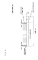
- FIG. 5 shows a frame format 500 according to the first embodiment of the present invention.
- a frame 510 which is described in the frame format 500 includes an active period 520 and an inactive period 530.
- the active period 520 is a period in which each of the communication terminals 120-1 to 120-3 performs communication, and has a plurality of time slots.
- the plurality of time slots of the active period 520 are shared among all the communication terminals existing within the network of the wireless communication system 100.
- the first time slot is allocated as a period for receiving a first beacon packet 541.
- the control device 110 broadcasts the first beacon packet 541 to the first to third communication terminals 120-1 to 120-3 which are all the communication terminals existing within the communication area 150.
- the first beacon packet 541 includes, as shown in FIG. 4 , control information concerning the frame 510, such as the number of time slots of the active period 520, allocation of the time slots, the length of the active period 520, the length of the inactive period 530, and a time until transmission of the next beacon packet.
- the time slots other than the first time slot are used for communication between the control device 110 and each of the communication terminals 120-1 to 120-3.
- the Slotted-CSMA may be used as a communication protocol.
- a part of the plurality of time slots may be reserved for each communication terminal, so that communication can be performed without a collision between communication terminals.
- a first half of the plurality of time slots of the active period is used for contention access, and a second half thereof is reserved for contention-free access.
- the inactive period 530 is a period in which each of the communication terminals 120-1 to 120-3 does not perform communication. In the inactive period 530, each of the communication terminals 120-1 to 120-3 is in a sleep mode, and thereby the power consumption is reduced.
- the frame format 500 according to the first embodiment is similar to the conventional frame format 50 shown in FIG. 14 .
- the frame format 500 according to the first embodiment of the present invention is different from the conventional frame format 50 shown in FIG. 14 , in that, among the plurality of time slots of the active period 520, the last time slot is allocated as a period for transmitting and receiving a second beacon packet 542.
- the control device 110 broadcasts the second beacon packet 542 to the first to third communication terminals 120-1 to 120-3 which are all the communication terminals existing within the communication area 150.
- the second beacon packet 542 may include control information concerning the frame 510, such as the number of time slots of the active period 520, allocation of the time slots, the length of the active period 52, the length of the inactive period 53, and a time until transmission of the next beacon packet, as shown in FIG. 4 .
- FIG. 6A shows the first beacon packet 541.
- the first beacon packet 541 notifies (advance notification) information concerning a candidate channel to which the use channel is possibly changed from the currently used channel.
- the first beacon packet 541 includes a channel page field (Ch.Page), a channel number field (Ch.No.), and a channel move field (Ch.Move).
- the channel page field specifies a set of channel numbers.
- the channel page field indicates a difference of frequency bands to be used, and is used for a selection of a frequency band for the communication terminal usable in a multiband, such as the 868 MHz band, the 915 MHz band, the 950 MHz band, and the 2.4 GHz band.
- a frequency band for the communication terminal usable in a multiband, such as the 868 MHz band, the 915 MHz band, the 950 MHz band, and the 2.4 GHz band.
- 5-bits binary data "00010" is set, which specifies "2" in decimal number.
- the channel page field indicates where in the order of frequency bands, which are preliminarily determined by a system, a frequency band is.
- the channel number field specifies a channel number in the frequency band specified by the channel page field.
- a channel bandwidth or the number of channels may be different for each frequency band. Correspondence between a channel number and an actual channel frequency is preliminarily defined within a communication system.
- the channel page field is represented in a 27-bit bit map.
- the bit 0 corresponds to the channel number 0
- the bit 1 corresponds to the channel number 1
- the bit 26 corresponds to the channel number 26, respectively.
- the bit 4 is set to be "1"
- a channel number 4 corresponding to the bit 4 is specified.
- the channel number field indicates a channel number in a frequency band which is preliminarily determined by the system.
- the channel move field specifies whether or not the use channel is to be changed to a channel that is specified by the channel page field and the channel number field. For example, when “0" is set in the channel move field, it indicates that the use channel is not to be changed from the currently used channel. On the other hand, when “1" is set in the channel move field, it indicates that the use channel is to be changed from the currently used channel to the channel specified by the channel page field and the channel number field. In FIG. 6A , "0" is set in the channel move field, which indicates that the use channel is not to be changed from the currently used channel. That is, the first beacon packet 541 is an advance notification for notifying information concerning a candidate channel to which the use channel is possibly changed, by using the channel page field and the channel number field. In other words, since the first beacon packet 541 is the advance notification for notifying the information concerning the candidate channel, a value in the channel move field is fixedly set to be "0".
- FIG. 6B shows the second beacon packet 542.
- a configuration of the second beacon packet 542 is the same as the first beacon packet 541 shown in FIG. 6A .
- " 1 " is set in the channel move field of the second beacon packet 542, which indicates that the use channel is to be changed from the currently used channel to the channel specified by the channel page field and the channel number field. That is, the second beacon packet 542 is a determinate notification for notifying that the use channel is to be changed to the channel number 4 of the channel page No. 2.
- a value in the channel move field is variable, that is, the value is set to be “1" when the use channel is to be changed, and set to be "0" when the use channel is not to be changed.
- the channel specified by the channel page field and the channel number field of the second beacon packet 542 may be either the same as or different from the channel specified by the channel page field and the channel number field of the first beacon packet 541.
- the first beacon packet 541 has to include at least the information concerning the candidate channel.
- the information concerning the candidate channel is information concerning one or a plurality of channels to which the use channel is possibly changed from the currently used channel in the next and subsequent frames.
- the second beacon packet 542 has to include at least the information of whether or not the use channel is to be changed from the currently used channel.
- the channel number is represented in a bit map form, but this is not limitative. For example, a method of representing the channel number in binary number may be adopted.
- the channel move field may be represented in a bit map form, in order to notify whether or not the use channel is to be changed from each communication terminal.
- the information concerning the candidate channel and the information of whether or not the use channel is to be changed may be represented in one or a plurality of bit fields, and may be provided for each communication terminal. Moreover, the one or the plurality of bit fields may be provided as a part of the control information of the beacon packet shown in FIG. 4 , or may be provided as a part of another control packet.
- FIG. 7 shows a situation in which the first communication terminal 120-1 changes the use channel by using the frame 510 which is described in the frame format 500 shown in FIG. 5 .
- communication of a frame 510-1 is performed using a channel CH1.
- the control device 110 transmits a first beacon packet 541-1 to the first communication terminal 120-1, to give an advance notification of the channel CH2 as the information concerning the candidate channel.
- the control device 110 determines that communication with the first communication terminal 120-1 cannot be normally performed in the channel CH1.
- the control device 110 transmits a second beacon packet 542-1 to the first communication terminal 120-1, to give a determinate notification that the use channel is to be changed from the currently used channel CH1 to the channel CH2 which is the candidate channel.
- the first communication terminal 120-1 changes the use channel from the channel CH1 to the channel CH2.
- the control device 110 and the first communication terminal 120-1 perform communication of a next frame 510-2, by using the channel CH2.
- the channel CH2 is largely influenced by interference from another network system, the use channel is further changed from the channel CH2 to the channel CH3.
- the determinate notification for changing the use channel is given by using the second beacon packet, in the last time slot of the active period of the frame that is determined, by the control device 110, to be largely influenced by interference from another network system.
- the first communication terminal 120-1 changes the use channel to a channel that is determined, by the determinate notification, to be a channel to which the use channel is to be changed, and enters the sleep mode.
- control device 110 and the first communication terminal 120-1 according to the present embodiment can, by using the channel to which the use channel has been changed, unfailingly communicate a next frame subsequent to the frame that has been determined, by the control device 110, to be largely influenced by interference from another network system.
- FIG. 8 shows a communication sequence between the control device 110 and each of the communication terminals 120-1 to 120-3 in the wireless communication system 100.
- the third communication terminal 120-3 is omitted.
- the control device 110 broadcasts the first beacon packet 541-1 to each of the communication terminals 120-1 and 120-2.
- Each of the communication terminals 120-1 and 120-2 receives the first beacon packet 541-1 from the control device 110, and acquires the control information included in the first beacon packet 541-1.
- the first beacon packet 541-1 includes the information concerning the candidate channel.
- the control device 110 and each of the communication terminals 120-1 and 120-2 communicate with each other.
- the channel used for the current communication is largely influenced by interference from another network system, and in the active period 520-1, communication from each of the communication terminals 120-1 and 120-2 to the control device 110 fails.
- the control device 110 determines that the communication with each of the communication terminals 120-1 and 120-2 cannot be normally performed with the currently used channel.
- the control device 110 broadcasts the second beacon packet 542-1 to each of the communication terminals 120-1 and 120-2.
- Each of the communication terminals 120-1 and 120-2 receives the second beacon packet 542-1 from the control device 110, and acquires the control information included in the second beacon packet 542-1.
- the second beacon packet 542-1 includes the information of whether or not the use channel is to be changed. Specifically, as shown in FIG. 6B , " 1 " is set in the channel move field, which indicates that the use channel is to be changed from the currently used channel to a channel specified by the channel page field and the channel number field.
- the control device 110 and each of the communication terminals 120-1 and 120-2 After the active period 520-1 ends, in the inactive period 530-1, the control device 110 and each of the communication terminals 120-1 and 120-2 perform a channel change process for changing the use channel to the channel notified in the second beacon packet 542-1, and then enters the sleep mode. In the inactive period 530-1, the control device 110 and each of the communication terminals 120-1 and 120-2 do not communicate with each other. In the inactive period 530-1, the control device 110 and each of the communication terminals 120-1 and 120-2 enter the sleep mode, and thereby power consumption can be reduced.
- the length of the inactive period 530-1 is preliminarily notified by the control information included in the beacon packet 540-1.
- the control device 110 and each of the communication terminals 120-1 and 120-2 recover from the sleep mode to the operation mode, and prepare for communication of the next frame.
- the control device 110 broadcasts the first beacon packet 541-2 to each of the communication terminals 120-1 and 120-2, by using the channel to which the use channel has been changed. Since the control device 110 and each of the communication terminals 120-1 and 120-2 have already changed the use channel to the previously notified channel, the first beacon packet 541-2 includes information concerning a candidate channel to which the use channel is possibly changed subsequently.
- the control device 110 and each of the communication terminals 120-1 and 120-2 communicate with each other by using the channel to which the use channel has been changed. Accordingly, in the active period 520-2, influence of interference from another network system can be avoided, and the communication from each of the communication terminals 120-1 and 120-2 to the control device 110 is successfully performed. In this case, the control device 110 determines that the use channel is not to be changed.
- the control device 110 broadcasts a second beacon packet 542-2 to each of the communication terminals 120-1 and 120-2.
- Each of the communication terminals 120-1 and 120-2 receives the second beacon packet 542-2 from the control device 110, and acquires the control information included in the second beacon packet 542-2.
- the second beacon packet 542-2 includes the information indicating that the use channel is not to be changed. Specifically, "0" is set in the channel move field shown in FIG. 6B , which indicates that the use channel is not to be changed from the currently used channel to a channel specified by the channel page field and the channel number field.
- a channel of the entire network can be changed in a short time after the control device 110 determines that influence of interference from another network system is large. This can reduce a possibility that congestion further increases due to a communication state in the network being deteriorated during a period from when the control device 110 determines that influence of interference from another network system is large to when the use channel is actually changed. Comparing a conventional communication sequence shown in FIG. 18 and the communication sequence according to the present embodiment shown in FIG.
- the control device 110 and the first communication terminal 120-1 can, by using the channel to which the used channel has been changed, unfailingly communicate a next frame subsequent to the frame that has been determined, by the control device 110, to be largely influenced by interference from another network system.
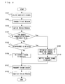
- FIG. 9 shows a control flow of the control device 110.
- the control device 110 selects a candidate channel to which the use channel is possibly changed from the currently used channel.
- the number of candidate channels may be one or more. In a case where a plurality of candidate channels are selected, it is preferred to prioritize the plurality of candidate channels.
- step S102 in the first time slot of the active period, the control device 110 broadcasts the first beacon packet to all the communication terminals within the communication area 150.
- the first beacon packet includes information concerning the candidate channel selected in step S101.
- step S103 the control device 110 performs an active period process.
- the control device 110 performs a communication process for communication with the communication terminals within the communication area 150.
- step S104 the control device 110 determines a state of the communication process performed in step S103.
- the control device 110 determines whether or not the number of communication errors exceeds a predetermined threshold value, in the communication process for communication with each of the communication terminals.
- the process advances to step S109.
- the process advances to step S105.
- step S105 the control device 110 determines whether or not interference from another network system is detected, based on information other than the number of communication errors. For example, when a reception level or a noise level exceeds a predefined threshold value in a time slot in which no communication is performed, it may be determined that some kind of interference signal exists.
- the process advances to step S109.
- the process advances to step S106.
- each communication terminal When each communication terminal detects a reception error for a communication packet from the control device 110, the communication terminal requests the control device 110 to re-transmit the communication packet.
- the determination of the communication state, which is performed in step S104 and step S105 may be performed based on whether or not there is the request for re-transmission.
- the determination of the communication state, which is performed in step S104 and step S105 is performed based also on information of the reception level. For example, when the reception level is low and a reception error occurs, the cause of the reception error is that a distance of communication between the control device 110 and each communication terminal is large. In this case, therefore, it may be determined that a communication failure due to interference does not occur. On the other hand, when a reception error occurs even though the reception level is high, it may be determined that the reception level rises because of superimposition of an interference signal, and thus it may be determined that a communication failure due to interference occurs.
- step S106 the control device 110 determines that the use channel is not to be changed, and sets "0" in the channel move field.
- step S109 the control device 110 determines that the use channel is to be changed, and determines a channel to which the use channel is to be actually changed. Then, in step S110, the control device 110 sets "1" in the channel move field.
- which channel the use channel is actually changed to is determined by various methods. For example, a channel sensing may be performed during the inactive period, and a channel in which less interference occurs may be selected.
- step S107 in the last time slot of the active period, the control device 110 broadcasts the second beacon packet to all the communication terminals within the communication area 150.
- the second beacon packet includes information concerning a channel to which the use channel is to be actually changed or information concerning a candidate channel, which are set in step S110 or step S106.
- step S108 the control device 110 performs an inactive period process.
- the control device 110 performs the channel change process and then enters the sleep mode.
- the control device 110 enters the sleep mode without any process. In this manner, the control device 110 completes a one-frame process.
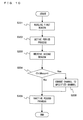
- FIG. 10 shows a control flow of each of the communication terminals 120-1 to 120-3. Here, a control flow of the first communication terminal 120-1 will be described.
- step S201 in the first time slot of the active period, the first communication terminal 120-1 receives the first beacon packet from the control device 110.
- the first beacon packet includes information concerning a candidate channel to which the use channel is possibly changed from the currently used channel.
- step S202 the first communication terminal 120-1 performs the active period process.
- the first communication terminal 120-1 performs the communication process for communication with the control device 110.
- step S203 in the last time slot of the active period, the first communication terminal 120-1 receives the second beacon packet from the control device 110.
- the second beacon packet includes information of whether or not the use channel is to be changed.
- step S204 when "1" is set in the channel move field included in the second beacon packet (Yes in step S204), the first communication terminal 120-1 advances the process to step S206. On the other hand, when "0" is set in the channel move field included in the second beacon packet (No in step S204), the first communication terminal 120-1 advances the process to step S205.
- step S206 the first communication terminal 120-1 performs the channel change process for changing the use channel, and then advances the process to step S205.
- step S205 the first communication terminal 120-1 performs the inactive period process. In order to reduce the power consumption, the first communication terminal 120-1 enters the sleep mode. In this manner, the first communication terminal 120-1 completes a one-frame process.
- the control device 110 broadcasts the first beacon packet 541 to the first to third communication terminals 120-1 to 120-3, in the first time slot of the active period; generates the second beacon packet 542 based on the communication state in the active period; and broadcasts the second beacon packet 542 in the last time slot of the active period. Accordingly, when the control device 110 determines that influence of interference from another network system is large in the communication with the first to third communication terminals 120-1 to 120-3, the control device 110 selects a channel from the plurality of channels so as to avoid the interference from another network system, and causes the communication terminals in the network to change the use channel, during the inactive period in the same frame.
- a time required for the channel change process varies for each communication terminal, and some communication terminals require a long time for the process of changing the use channel.
- all the communication terminals perform the channel change process during the inactive period. Therefore, at the start of the active period in the next frame, communication can be unfailingly performed by using the channel to which the use channel has been changed.
- the control device 110 and each of the communication terminals 120-1 to 120-3 do not communicate with each other in the inactive period. Therefore, a time for the sleep mode can be ensured. That is, the control device 110 and each of the communication terminals 120-1 to 120-3 can ensure low power consumption.
- each of the communication terminals 120-1 to 120-3 successfully receives the first beacon packet and the second beacon packet from the control device 110, has been described.
- FIG. 11 shows a control flow of each of communication terminals 120-1 to 120-3 according to the second embodiment of the present invention.
- a control flow of the first communication terminal 120-1 will be described.
- the process in steps S201 to S206 is the same as that in the first communication terminal 120-1 according to the first embodiment of the present invention shown in FIG. 10 , and therefore a description thereof is omitted.
- step S210 the first communication terminal 120-1 determines whether or not the first beacon packet is received without an error.
- a subsequent process is the same as the process in the first communication terminal 120-1 according to the first embodiment of the present invention shown in FIG. 10 .
- the process advances to step S211.
- the first communication terminal 120-1 changes the use channel to a candidate channel set in the beacon packet.
- the beacon packet previously successfully received may be either the first beacon packet or the second beacon packet.
- a plurality of candidate channels are set in the beacon packet previously successfully received, one of them may be arbitrarily selected.
- the plurality of candidate channels are prioritized, the highest-priority channel may be selected.
- step S212 the first communication terminal 120-1 determines whether or not a next beacon packet from the control device 110 is received without an error by using the channel to which the use channel has been changed in step S211.
- the process goes to step S204, and a subsequent process is the same as the process in the first communication terminal 120-1 according to the first embodiment of the present invention shown in FIG. 10 .
- the reception fails (No in step S212)
- the process advances to step S213.
- the first communication terminal 120-1 repeats the process in steps S211 and S212 for a predetermined time period or over a predetermined number of times (No in step S213). That is, based on a beacon packet previously successfully received, the first communication terminal 120-1 changes the use channel to a candidate channel set in the beacon packet, and repeats the process in steps S211 and S212 until the first communication terminal 120-1 can receive a next beacon packet from the control device 110, by using the channel to which the use channel has been changed.
- the use channel may be changed sequentially.
- step 213 when the next beacon packet from the control device 110 cannot be received even though the process in steps S211 and S212 is repeated for the predetermined time period or over the predetermined number of times (Yes in step S213), the first communication terminal 120-1 advances the process to step S214.
- step S214 the first communication terminal 120-1 performs a process for detecting a beacon packet from all channels and resynchronizing the beacon packet.
- the control device 110 broadcasts the first beacon packet 541 to the first to third communication terminals 120-1 to 120-3, in the first time slot of the active period; generates the second beacon packet 542 based on the communication state in the active period; and broadcasts the second beacon packet 542 in the last time slot of the active period.
- a candidate channel is set in the first beacon packet 541 or the second beacon packet 542 previously successfully received, and therefore each of the communication terminals 120-1 to 120-3 can change the use channel to the candidate channel.
- each of the communication terminals 120-1 to 120-3 can search for a channel used by the control device 110 with a smaller number of channels being scanned and for a shorter time.
- each of the communication terminals 120-1 to 120-3 fails to receive the first beacon packet from the control device 110.
- a case where each of the communication terminals 120-1 to 120-3 fails to receive the second beacon packet from the control device 110, will be described.
- FIG. 12 shows a communication sequence between the control device 110 and each of the communication terminals 120-1 to 120-3 in the wireless communication system 100, in a case where a reception of the second beacon packet fails.
- the communication sequence shown in FIG. 12 is basically the same as the communication sequence according to the first embodiment of the present invention shown in FIG. 8 , and therefore a detailed description is omitted. In the present embodiment, points where the communication sequence according to the present embodiment is different from the communication sequence according to the first embodiment shown in FIG. 8 will be described.
- the control device 110 and each of the communication terminals 120-1 and 120-2 communicate with each other, but communication errors occur.
- the control device 110 broadcasts the second beacon packet 542-1 to each of the communication terminals 120-1 and 120-2.
- the first communication terminal 120-1 successfully receives the second beacon packet 542-1.
- the first communication terminal 120-1 After the active period 520-1 ends, in the inactive period 530-1, the first communication terminal 120-1 performs the channel change process for changing the use channel to a channel notified in the second beacon packet 542-1, and then enters the sleep mode.
- the active period 520-2 the first communication terminal 120-1 performs communication using the channel to which the use channel has been changed. Accordingly, in the active period 520-2, influence of interference from another network system can be avoided, and the communication from the first communication terminal 120-1 to the control device 110 is successfully performed.
- the second communication terminal 120-2 fails to receive the second beacon packet 542-1.
- the second communication terminal 120-2 does not perform the channel change process and enters the sleep mode, because the second communication terminal 120-2 has not acquired information of whether or not the use channel is to be changed, which should have been notified in the second beacon packet 542-1.
- the control terminal 110 since communication errors occurred between the control terminal 110 and the second communication terminal 120-2, the control terminal 110 has performed the channel change process for changing the use channel.
- the second communication terminal 120-2 tries to communicate using the channel which has not been changed, and the control terminal 110 transmits the first beacon packet 541-2 using the channel to which the use channel has been changed.
- the second communication terminal 120-2 executes the process on or after No in step S210 of FIG. 11 , which has been described in the second embodiment of the present invention.
- the second communication terminal 120-2 when the second communication terminal 120-2 fails to receive the second beacon packet 542-1, the second communication terminal 120-2 enters the sleep mode without performing the channel change process in the inactive period 530-1 after the active period 520-1 ends.
- the second communication terminal 120-2 may, based on a beacon packet previously successfully received, change the use channel to a candidate channel set in the beacon packet.
- the control device 110 broadcasts the first beacon packet 541 to the first to third communication terminals 120-1 to 120-3, in the first time slot of the active period; generates the second beacon packet 542 based on the communication state in the active period; and broadcasts the second beacon packet 542 in the last time slot of the active period.
- a candidate channel is set in the first beacon packet 541 or the second beacon packet 542 previously successfully received, and therefore each of the communication terminals 120-1 to 120-3 can change the use channel to the candidate channel.
- each of the communication terminals 120-1 to 120-3 can search for a channel used by the control device 110 with a smaller number of channels being scanned and for a shorter time.
- each configuration according to the first to third embodiments described above may be realized as an LSI (Large Scale Integration) which is an integrated circuit. These configurations may be formed into one chip, or a part or the whole of the configurations may be included in one chip.
- the LSI is mentioned herein, it may also be called an IC (Integrated Circuit), a system LSI, a super LSI, or an ultra LSI, depending on the difference in the degree of integration.
- the method for circuit-integration is not limited to the LSI, and may be realized through circuit-integration of a dedicated circuit or a general-purpose processor.
- an FPGA Field Programmable Gate Array
- a reconfigurable processor that is capable of reconstituting connections and configurations of a circuit cell within the LSI
- arithmetic processing of these function blocks may be performed by using, for example, a DSP, a CPU (Central Processing Unit), and the like.
- these processing steps may be recorded as a program on a recording medium, and may be executed.
- control device and the communication terminal of the present invention are useful for, for example, a wireless communication system that is used for a sensor network or a wireless communication network using an active RF (Radio Frequency) tag.
- active RF Radio Frequency
Abstract
Description
- The present invention relates to a control device, a communication terminal, a control method, and a communication method, which are used for a wireless communication system, and more particularly relates to a control device, a communication terminal, a control method, and a communication method, which avoid interference caused by a plurality of channels being used in a sensor network or a wireless communication network using an active RF (Radio Frequency) tag.
- In recent years, there has been an increasing interest in a network that uses a small-size, low-power-consumption wireless terminal, such as a WPAN (Wireless Personal Area Network) and a sensor network. Also, as a system similar to the network, an active RF tag system that transmits a wireless signal by itself, can be mentioned.
-
FIG. 13 shows a conventionalwireless communication system 10. InFIG. 13 , thewireless communication system 10 includes a control device (AP: Access Point) 11, and first to third communication terminals (STA: Station) 12-1 to 12-3. The first to third communication terminals 12-1 to 12-3 exist within acommunication area 15 of thecontrol device 11. Thecontrol device 11 periodically broadcasts a beacon packet to the first to third communication terminals 12-1 to 12-3 which are all the communication terminals existing within thecommunication area 15. The beacon packet includes control information. The first to third communication terminals 12-1 to 12-3 receive the beacon packet from thecontrol device 11, and communicate with thecontrol device 11 based on the control information included in the beacon packet. - Here, in the
wireless communication system 10, various methods can be adopted as an access method for access between thecontrol device 11 and each of the communication terminals 12-1 to 12-3. For example, CSMA (Carrier Sense Multiple Access), TDMA (Time Division Multiple Access), FDMA (Frequency Division Multiple Access), SDMA (Space Division Multiple Access), and the like, can be mentioned as the access method. - In a network of the
wireless communication system 10, a transmission speed is low (several kbps to several hundred kbps), and a distance traveled by a wireless signal is short (approximately several meters to several tens of meters). On the other hand, each of the communication terminals 12-1 to 12-3 is characterized by having a small size and low power consumption that allows the communication terminal to be driven by a battery for several years. Accordingly, in order to reduce power consumption of each of the communication terminals 12-1 to 12-3, a communication protocol and a frame format are devised. For example, a frame format including an active period in which each of the communication terminals 12-1 to 12-3 performs communication and an inactive period in which each of the communication terminals 12-1 to 12-3 does not perform communication is used. In the inactive period, each of the communication terminals 12-1 to 12-3 does not perform communication and therefore can be in a sleep mode. That is, by setting the inactive period long, a time period in which each of the communication terminals 12-1 to 12-3 is in the sleep mode becomes long, and thus the power consumption can be reduced. -
FIG. 14 shows aconventional frame format 50. InFIG. 14 , aframe 51 which is described in aframe format 50 includes anactive period 52 and aninactive period 53. - The
active period 52 is a period in which each of the communication terminals 12-1 to 12-3 performs communication, and has a plurality of time slots. The plurality of time slots of theactive period 52 are shared among all the communication terminals existing within the network of thewireless communication system 10. - Among the plurality of time slots of the
active period 52, the first time slot is allocated as a period for transmitting and receiving abeacon packet 54. In the first time slot, thecontrol device 11 broadcasts thebeacon packet 54 to the first to third communication terminals 12-1 to 12-3 which are all the communication terminals existing within thecommunication area 15. Thebeacon packet 54 includes control information concerning theframe 51, such as the number of time slots of theactive period 52, allocation of the time slots, the length of theactive period 52, the length of theinactive period 53, and a time until transmission of the next beacon packet. - Among the plurality of time slots of the
active period 52, the time slots other than the first time slot are used for communication between thecontrol device 11 and each of the communication terminals 12-1 to 12-3. - On the other hand, the
inactive period 53 is a period in which each of the communication terminals 12-1 to 12-3 does not perform communication. In theinactive period 53, each of the communication terminals 12-1 to 12-3 is in a sleep mode, and thereby the power consumption is reduced. -
FIG. 15 shows a communication sequence between thecontrol device 11 and each of the communication terminals 12-1 to 12-3 in thewireless communication system 10. Here, for convenience of the description, the third communication terminal 12-3 is omitted. - In the first time slot of an active period 52-1, the
control device 11 broadcasts a beacon packet 54-1 to each of the communication terminals 12-1 and 12-2. Each of the communication terminals 12-1 and 12-2 receives the beacon packet 54-1 from thecontrol device 11, and acquires control information included in the beacon packet 54-1. - Subsequently, in the active period 52-1, the
control device 11 and each of the communication terminals 12-1 and 12-2 communicate with each other. For example, each of the communication terminals 12-1 and 12-2 transmits data to thecontrol device 11, and, in response thereto, thecontrol device 11 transmits response data to each of the communication terminals 12-1 and 12-2. - In an inactive period 53-1, the
control device 11 and each of the communication terminals 12-1 and 12-2 do not communicate with each other. In the inactive period 53-1, thecontrol device 11 and each of the communication terminals 12-1 and 12-2 enter the sleep mode, and thereby power consumption can be reduced. Here, the length of the inactive period 53-1 is preliminarily notified by the control information included in the beacon packet 54-1. - When the inactive period 53-1 ends and a next active period 52-2 starts, the
control device 11 and each of the communication terminals 12-1 and 12-2 recover from the sleep mode to an operation mode, and prepare for communication of a next frame. - In the active period 52-2, in the first time slot, the
control device 11 broadcasts the beacon packet 54-1 to each of the communication terminals 12-1 and 12-2. Then, by repeating the same process described above, thecontrol device 11 and each of the communication terminals 12-1 and 12-2 communicate with each other. - As shown in
FIG. 15 , in the active period 52-2, communication from the first communication terminal 12-1 to thecontrol device 11 fails. Although data is transmitted from the first communication terminal 12-1 to thecontrol device 11, thecontrol device 11 cannot properly receive the data transmitted from the first communication terminal 12-1. In this case, thecontrol device 11 cannot transmit response data to the first communication terminal 12-1. Since no response data is transmitted from thecontrol device 11 even when a predetermined time period elapses, the first communication terminal 12-1 determines that the communication fails. Then, the first communication terminal 12-1 re-transmits data to thecontrol device 11. Here, it is assumed that thecontrol device 11 can properly receive the data re-transmitted from the first communication terminal 12-1. In this case, in response to the re-transmitted data, thecontrol device 11 transmits response data to the first communication terminal 12-1, and the communication successfully completes. -
FIG. 16 shows a channel band of a wireless channel.FIG. 16 shows a spectrum mask for channels CH1 to CH6, with the horizontal axis indicating a frequency. First tosixth channel bands 91 to 96 are channel bands of the channels CH1 to CH6, respectively. - The
control device 11 selects a channel to be used for communication, from the channels CH1 to CH6, and broadcasts a beacon packet to the first to third communication terminals 12-1 to 12-3 which are all the communication terminals existing within thecommunication area 15. Each of the communication terminals 12-1 to 12-3 performs channel scanning, and participates in a network of a channel through which a beacon packet is received. In this manner, communication between thecontrol device 11 and each of the communication terminals 12-1 to 12-3, which exist in thecommunication area 15 managed by thecontrol device 11, starts. - A frequency band used by the network of the
wireless communication system 10 described above is often shared with another network system. This causes a problem of interference between systems or between networks. - For example, at the 950 MHz band, a passive RF tag and an active RF tag partly use the same channel. At the 2.4 GHz band, more network systems such as a wireless LAN share a frequency band. Moreover, in a case where a system having large transmission power is used in an adjacent frequency band, for example, in a case where a mobile phone or the like is used, a wireless terminal which uses a simple, small-size radio frequency component such as an active RF tag cannot obtain channel selectivity and thus may suffer from interference.
- In a frequency band in which interference from another network system is large, it is necessary to select a channel from a plurality of channels so as to avoid the interference from the another network system and to change a channel used by the communication terminal within the network.
-
FIG. 17 shows a situation in which the first communication terminal 12-1 changes a use channel by using theframe 51 which is described in theframe format 50 shown inFIG. 14 . InFIG. 17 , communication of a frame 51-1 is performed using a channel CH1. Here, it is assumed that, in the active period 52-1, the channel CH1 is largely influenced by interference from another network system. Thecontrol device 11 determines that communication with the first communication terminal 12-1 cannot be normally performed with the channel CH1, and transmits information for changing a use channel from the channel CH1 to a channel CH2 by using a beacon packet 54-2. - In the active period 52-2, the first communication terminal 12-1 receives the beacon packet 54-2 including information for changing the use channel from the channel CH1 to the channel CH2. However, in the active period 52-2, the
control device 11 and the first communication terminal 12-1 communicate with each other by using the channel CH1, and after the active period 52-2 ends, in an inactive period 53-2, the use channel is changed to the channel CH2. - Then, for a next frame 51-3, the
control device 11 and the first communication terminal 12-1 communicate with each other by using the channel CH2. When it is determined in the active period 52-3 that the channel CH2 is largely influenced by interference from another network system, the use channel is further changed from the channel CH2 to a channel CH3. - In this manner, in a frequency band that suffers from large interference from another network system, the
control device 11 selects a channel to be used for communication from the channels CH1 to CH6 so as to avoid the interference from the another network system, and causes each communication terminal within the network to change a use channel. -
Patent Literature 1 discloses a method of avoiding interference by performing communication using the channel CH2 in an inactive period, in a case where it is determined in an active period that the channel CH1 is largely influenced by interference from another network system. -
- Patent Literature 1: Japanese Laid-Open Patent Publication No.
2007-143095 - However, each communication terminal receives a beacon packet from a control device, only in a first time slot of an active period. Therefore, even if the communication terminal acquires information concerning a channel change, which is included in the received beacon packet, the communication terminal actually performs communication using the changed channel, from an active period of a next frame. That is, the control device and each communication terminal spend a long time before a channel is changed for avoiding interference from another network system and the control device and each communication terminal can actually communicate with each other by using the changed channel.
- In a system that sets the inactive period long in order to reduce power consumption of each communication terminal, a time until a next active period is long, and therefore a longer time is spent before communication can be actually performed by using the changed channel.
- A situation in which each communication terminal within the network changes the use channel in a case where influence of interference from another network system is large, will be specifically described.
-
FIG. 18 shows a communication sequence between thecontrol device 11 and each of the communication terminals 12-1 to 12-3 in thewireless communication system 10. Here, for convenience of the description, the third communication terminal 12-3 is omitted. - In the first time slot of the active period 52-1, the
control device 11 broadcasts the beacon packet 54-1 to each of the communication terminals 12-1 and 12-2. Each of the communication terminals 12-1 and 12-2 receives the beacon packet 54-1 from thecontrol device 11, and acquires control information included in the beacon packet 54-1. - Subsequently, in the active period 52-1, the
control device 11 and each of the communication terminals 12-1 and 12-2 communicate with each other. Here, a currently used channel is largely influenced by interference from another network system, and thus, in the active period 52-1, communication from each of the communication terminals 12-1 and 12-2 to thecontrol device 11 fails. In this case, thecontrol device 11 determines that communication with each of the communication terminals 12-1 and 12-2 cannot be normally performed with the currently used channel. - However, information for changing a use channel from a currently used channel to another channel cannot be notified in an inactive period in which each of the communication terminals 12-1 and 12-2 is in the sleep mode. Accordingly, the
control device 11 notifies the information to each of the communication terminals 12-1 and 12-2, in the next active period 52-2. - In the inactive period 53-1, the
control device 11 and each of the communication terminals 12-1 and 12-2 do not communicate with each other. In the inactive period 53-1, thecontrol device 11 and each of the communication terminals 12-1 and 12-2 enter the sleep mode, and thereby power consumption can be reduced. Here, the length of the inactive period 53-1 is preliminarily notified by the control information included in the beacon packet 54-1. - When the inactive period 53-1 ends and the next active period 52-2 starts, the
control device 11 and each of the communication terminals 12-1 and 12-2 recover from the sleep mode to the operation mode, and prepare for communication of a next frame. - In the active period 52-2, in the first time slot, the
control device 11 broadcasts the beacon packet 54-2 to each of the communication terminals 12-1 and 12-2. Here, the beacon packet 54-2 includes information for changing a use channel, but in the active period 52-2, each of the communication terminals 12-1 and 12-2 performs communication by using the channel that has been used in the immediately preceding active period 52-1. Therefore, there is still large influence of interference from another network system, and communication from each of the communication terminals 12-1 and 12-2 to thecontrol device 11 fails. - After the active period 52-2 ends, in the inactive period 53-2, the
control device 11 and each of the communication terminals 12-1 and 12-2 perform a channel change process for changing the use channel to the channel notified in the beacon packet 54-2, and then enter the sleep mode. - After the inactive period 53-2 ends, in the first time slot of an active period 52-3, the
control device 11 broadcasts a beacon packet 54-3 to each of the communication terminals 12-1 and 12-2, by using the changed channel. - Then, in the active period 52-3, the
control device 11 and each of the communication terminals 12-1 and 12-2 communicate with each other by using the changed channel, and thereby avoid interference from another network system. - In this manner, when the information for changing the use channel is notified by using the beacon packet in the first time slot of the active period, a long time is spent before a channel change is completed. Therefore, when communication is actually performed by using the changed channel, circumstances within the network may already be changed.
- Even though it is determined in the active period 52-1 that the currently used channel is largely influenced by interference from another network system, the same channel is used in the active period 52-2. Moreover, if, in the active period 52-2, each of the communication terminals 12-1 and 12-2 repeatedly performs re-transmission for the failure in the active period 52-1, congestion further increases. Additionally, in a case where a communication terminal (not shown), which has not participated in the network of the
communication area 15 of thecontrol device 11 in the active period 52-1, newly participates in the network in the active period 52-2, a possibility that communication packets collide with each other increases, and the congestion further increases. - Furthermore, a beacon packet including the information for changing the use channel may be transmitted in the inactive period, so that a change of the use channel is completed before the next active period starts. However, each communication terminal cannot enter the sleep mode because the communication terminal performs communication in the inactive period. Thus, power consumption cannot be reduced.
- Therefore, an object of the present invention is to unfailingly realize communication between a control device and a communication terminal by using a channel that is changed in a manner that: the control device selects a channel from a plurality of channels so as to avoid interference from another network system, when the control device determines that there is large influence of interference from another network system in communication with the communication terminal; and the control device causes the communication terminal within a network to change a use channel in a short time.
- To achieve the above object, a control device according to the present invention is a control device which manages a communication terminal within a communication area and communicates with the communication terminal in an active period by using a plurality of predetermined frequency channels, the control device comprising: a first beacon packet generation section that generates a first beacon packet which includes information indicating the active period and one or more candidate channels to which a use channel is possibly changed from a currently used channel; a first beacon packet transmission section that transmits the first beacon packet to the communication terminal, at the beginning of the active period; a second beacon packet generation section that: determines whether or not the use channel is to be changed, based on a state of communication with the communication terminal in the active period indicated by the transmitted first beacon packet; and generates a second beacon packet which includes information of whether or not the use channel is to be changed; a second beacon packet transmission section that transmits the second beacon packet to the communication terminal, at the end of the active period; and a channel change processing section that: when the second beacon packet generation section determines that the use channel is to be changed, changes the use channel to a change channel different from the currently used channel, after the active period ends and before a next active period starts; and, when the second beacon packet generation section determines that the use channel is not to be changed, maintains the currently used channel as the use channel.
- It is preferred that, when the second beacon packet generation section determines that the use channel is to be changed, the second beacon packet includes the change channel, and, when the second beacon packet generation section determines that the use channel is not to be changed, the second beacon packet includes one or more candidate channels to which the use channel is possibly changed from the currently used channel.
- Furthermore, it is preferred that the change channel is any of the one or more candidate channels included in the first beacon packet, or the change channel is a channel different from the one or more candidate channels included in the first beacon packet.
- Furthermore, it is preferred that the first beacon packet includes a plurality of candidate channels of which a priority order is defined.
- Furthermore, it is preferred that, when the number of communication errors occurring in communication with the communication terminal in the active period exceeds a predetermined threshold value, it is determined that the use channel is to be changed.
- To achieve the above object, a communication terminal according to the present invention is a communication terminal which is managed by a control device of a communication area to which the communication terminal belongs, and communicates with the control device in an active period by using any of a plurality of predetermined frequency channels, the communication terminal comprising: a first beacon packet reception section that receives, from the control device, a first beacon packet which includes information indicating the active period and one or more candidate channels to which a use channel is possibly changed from a currently used channel, at the beginning of the active period; a second beacon packet reception section that receives, from the control device, a second beacon packet which includes information of whether or not the use channel is to be changed, at the end of the active period; and a channel change processing section that, based on the information of whether or not the use channel is to be changed which is included in the second beacon packet, when the use channel is to be changed, changes the use channel to a change channel different from the currently used channel after the active period ends and before a next active period starts, and, when the use channel is not to be changed, maintains the currently used channel as the use channel.
- It is preferred that, when the use channel is to be changed, the second beacon packet includes the change channel, and, when the use channel is not to be changed, the second beacon packet includes one or more candidate channels to which the use channel is possibly changed from the currently used channel.
- Furthermore, it is preferred that the change channel is any of the one or more candidate channels included in the first beacon packet, or the change channel is a channel different from the one or more candidate channels included in the first beacon packet.
- Furthermore, it is preferred that the first beacon packet includes a plurality of candidate channels of which a priority order is defined.
- Additionally, it is preferred that, when the first beacon packet reception section fails to receive the first beacon packet, the channel change processing section changes the use channel to a change channel different from the currently used channel.
- Furthermore, it is preferred that the change channel is the one or more candidate channels included in the first beacon packet or the second beacon packet which has been previously successfully received.
- Moreover, it is preferred that, when the second beacon packet reception section fails to receive the second beacon packet, the channel change processing section changes the use channel to a change channel different from the currently used channel.
- Furthermore, it is preferred that the change channel is the one or more candidate channels included in the first beacon packet or the second beacon packet which has been previously successfully received.
- Furthermore, to achieve the above object, a wireless communication system according to the present invention includes the control device and the communication terminal described above.
- To achieve the above object, a control method according to the present invention is a control method performed by a control device which manages a communication terminal within a communication area and communicates with the communication terminal in an active period by using a plurality of predetermined frequency channels, the control method comprising: a first beacon packet generation step of generating a first beacon packet which includes information indicating the active period and one or more candidate channels to which a use channel is possibly changed from a currently used channel; a first beacon packet transmission step of transmitting the first beacon packet to the communication terminal at the beginning of the active period; a second beacon packet generation step of: determining whether or not the use channel is to be changed, based on a state of communication with the communication terminal in the active period indicated by the transmitted first beacon packet; and generating a second beacon packet which includes information of whether or not the use channel is to be changed; a second beacon packet transmission step of transmitting the second beacon packet to the communication terminal at the end of the active period; and a channel change processing step of: when the second beacon packet generation section determines that the use channel is to be changed, changes the use channel to a change channel different from the currently used channel, after the active period ends and before a next active period starts; and, when the second beacon packet generation section determines that the use channel is not to be changed, maintains the currently used channel as the use channel.
- To achieve the above object, a communication method according to the present invention is a communication method performed by a communication terminal which is managed by a control device of a communication area to which the communication terminal belongs, and communicates with the control device in an active period by using any of a plurality of predetermined frequency channels, the communication method comprising: a first beacon packet reception step of receiving, from the control device, a first beacon packet which includes information indicating the active period and one or more candidate channels to which a use channel is possibly changed from a currently used channel, at the beginning of the active period; a second beacon packet reception step of receiving, from the control device, a second beacon packet which includes information of whether or not the use channel is to be changed, at the end of the active period; and a channel change processing step of, based on the information of whether or not the use channel is to be changed which is included in the second beacon packet, when the use channel is to be changed, changes the use channel to a change channel different from the currently used channel after the active period ends and before a next active period starts, and, when the use channel is not to be changed, maintains the currently used channel as the use channel.
- A sequence of steps of the control method and the communication method described above which are performed by the control device and the communication terminal, respectively, may be provided in the form of a program for causing a computer to perform the process steps. The program may be recorded on a computer-readable storage medium and, in such a mode, introduced into the computer.
- As described above, according to the present invention, when the control device determines that influence of interference from another network system is large in communication with the communication terminal, the control device selects a channel from a plurality of channels so as to avoid the interference from the another network system, and causes the communication terminal within the network to change the use channel in a short time. Thereby, communication between the control device and the communication terminal can be unfailingly realized by using the changed channel.
-
- [
FIG. 1A] FIG. 1A shows awireless communication system 100 according to a first embodiment of the present invention. - [
FIG. 1B] FIG. 1B shows acontrol device 110 and communication terminals 120-1 to 120-3, which form thewireless communication system 100 according to the first embodiment of the present invention. - [
FIG. 2] FIG. 2 shows the communication terminals 120-1 to 120-3. - [
FIG. 3] FIG. 3 shows a hardware block diagram of a modulation section 123, ademodulation section 124, and a radio frequency section 125, which are shown inFIG. 2 . - [
FIG. 4] FIG. 4 shows acommunication packet 400. - [
FIG. 5] FIG. 5 shows aframe format 500 according to the first embodiment of the present invention. - [
FIG. 6A] FIG. 6A shows afirst beacon packet 541. - [
FIG. 6B] FIG. 6B shows asecond beacon packet 542. - [
FIG. 7] FIG. 7 shows a situation in which the first communication terminal 120-1 changes a use channel by using aframe 510 which is described in theframe format 500 shown inFIG. 5 . - [
FIG. 8] FIG. 8 shows a communication sequence between thecontrol device 110 and each of the communication terminals 120-1 to 120-3 in thewireless communication system 100. - [
FIG. 9] FIG. 9 shows a control flow of thecontrol device 110. - [
FIG. 10] FIG. 10 shows a control flow of each of the communication terminals 120-1 to 120-3. - [
FIG. 11] FIG. 11 shows a control flow of each of the communication terminals 120-1 to 120-3 according to a second embodiment of the present invention. - [
FIG. 12] FIG. 12 shows a communication sequence between thecontrol device 110 and each of the communication terminals 120-1 to 120-3 in thewireless communication system 100, in a case where a reception of the second beacon packet fails. - [
FIG. 13] FIG. 13 shows a conventionalwireless communication system 10. - [
FIG. 14] FIG. 14 shows aconventional frame format 50. - [
FIG. 15] FIG. 15 shows a communication sequence between acontrol device 11 and each of communication terminals 12-1 to 12-3 in thewireless communication system 10. - [
FIG. 16] FIG. 16 shows an example of a channel bandwidth of a wireless channel. - [
FIG. 17] FIG. 17 shows a situation in which the first communication terminal 12-1 changes a use channel by using aframe 51 which is described in theframe format 50 shown inFIG. 14 . - [
FIG. 18] FIG. 18 shows a communication sequence between thecontrol device 11 and each of the communication terminals 12-1 to 12-3 in thewireless communication system 10. - Hereinafter, embodiments of the present invention will be described with reference to the drawings.
-
FIG. 1A shows awireless communication system 100 according to a first embodiment of the present invention. InFIG. 1A , thewireless communication system 100 includes a control device (AP: Access Point) 110 and first to third communication terminals (STA: Station) 120-1 to 120-3. The first to third communication terminals 120-1 to 120-3 exist within acommunication area 150 of thecontrol device 110. Thecontrol device 110 periodically broadcasts a beacon packet to the first to third communication terminals 120-1 to 120-3 which are all the communication terminals existing within thecommunication area 150. The beacon packet includes control information. Each of the first to third communication terminals 120-1 to 120-3 receives the beacon packet from thecontrol device 110, and communicates with thecontrol device 110 based on the control information included in the beacon packet. In this manner, a configuration of thewireless communication system 100 is basically the same as a configuration of thewireless communication system 10 shown inFIG. 13 . -
FIG. 1B shows thecontrol device 110 and the communication terminals 120-1 to 120-3, which form thewireless communication system 100 according to the first embodiment of the present invention. InFIG. 1B , thecontrol device 110 includes a first beacon packet generation section 1101, a first beaconpacket transmission section 1102, adata communication section 1103, a second beaconpacket generation section 1104, a second beaconpacket transmission section 1105, and a channelchange processing section 1106. The first communication terminal 120-1 includes a first beacon packet reception section 1201, adata communication section 1202, a second beacon packet reception section 1203, and a channelchange processing section 1204. Although herein a description is given taking the first communication terminal 120-1 as an example, configurations and operations of the second communication terminal 120-2 and the third communication terminal 120-3 are the same as those of the first communication terminal 120-1. - The first beacon
packet transmission section 1102 of thecontrol device 110 transmits, to the first communication terminal 120-1, a first beacon packet generated by the first beacon packet generation section 1101. The first beacon packet reception section 1201 of the first communication terminal 120-1 receives the first beacon packet from thecontrol device 110. Then, based on the first beacon packet, thedata communication section 1103 of thecontrol device 110 and thedata communication section 1202 of the first communication terminal 120-1 communicate with each other. - The second beacon
packet generation section 1104 of thecontrol device 110 determines whether or not a use channel is to be changed from a currently used channel to another channel, based on a state of the communication between thecontrol device 110 and the first communication terminal 120-1. Then, the second beaconpacket generation section 1104 of thecontrol device 110 generates a second beacon packet which includes information of whether or not the use channel is to be changed. - The second beacon
packet transmission section 1105 of thecontrol device 110 transmits, to the first communication terminal 120-1, the second beacon packet generated by the second beaconpacket generation section 1104. The second beacon packet reception section 1203 of the first communication terminal 120-1 receives the second beacon packet from thecontrol device 110. Then, the channelchange processing section 1204 of the first communication terminal 120-1 changes the use channel based on the information of whether or not the use channel is to be changed, which is included in the second beacon packet. - On the other hand, the channel
change processing section 1106 of thecontrol device 110 changes the use channel, based on the determination, which has been performed by the second beaconpacket generation section 1104, of whether or not the use channel is to be changed. - Contents and transmission/reception timings of the first beacon packet, contents and transmission/reception timings of the second beacon packet, and the determination of whether or not the use channel is to be changed, will be described in detail later.
-
FIG. 2 shows the communication terminals 120-1 to 120-3. InFIG. 2 , each of the communication terminals 120-1 to 120-3 includes acontrol section 121, a memory 122, a modulation section 123, ademodulation section 124, a radio frequency section 125, and anantenna 126. - The
control section 121 processes transmission data and reception data, based on an operation state of each of the communication terminals 120-1 to 120-3, which is held in the memory 122. Thecontrol section 121 generates the transmission data. The modulation section 123 converts the transmission data generated by thecontrol section 121, into a transmission signal. The radio frequency section 125 converts the transmission signal resulting from the conversion performed by the modulation section 123, into a wireless signal, and transmits the wireless signal through theantenna 126. On the other hand, the wireless signal received by theantenna 126 is converted into a reception signal by the radio frequency section 125. Thedemodulation section 124 converts the reception signal resulting from the conversion performed by the radio frequency section 125, into reception data, and outputs the reception data to thecontrol section 121. -
FIG. 3 shows a hardware block diagram of the modulation section 123, thedemodulation section 124, and the radio frequency section 125, which are shown inFIG. 2 . InFIG. 3 , the modulation section 123 includes an encoding section 131 and a digital modulation section 132, and thedemodulation section 124 includes a decoding section 133 and adigital demodulation section 134. The radio frequency section 125 includes a digital-analog conversion section (DAC) 135, a low pass filter (LPF) 136, amixer 137, a band pass filter (BPF) 138, a power amplifier (PA) 139, a low noise amplifier (LNA) 140, a band pass filter (BPF) 141, amixer 142, a low pass filter (LPF) 143, a variable gain amplifier (VGA) 144, an analog-digital conversion section (ADC) 145, and alocal oscillator 146. - In the modulation section 123, the encoding section 131 encodes the transmission data inputted from the
control section 121. The digital modulation section performs a digital modulation on the transmission data which has been encoded by the encoding section 131, and outputs resultant data as a transmission signal, to the radio frequency section 122. In the radio frequency section 122, the DAC 135 converts the inputted transmission signal from digital to analog. The transmission signal converted into analog has its frequency adjusted by themixer 137 via theLPF 136. Moreover, the transmission signal having its frequency adjusted is, via the BPF 138, power-amplified by thePA 139, and transmitted as a wireless signal through theantenna 126. On the other hand, a wireless signal received by theantenna 126 is inputted to the radio frequency section 122. In the radio frequency section 122, theLNA 140 power-amplifies an inputted reception signal. The power-amplified reception signal has its frequency adjusted by themixer 142 via theBPF 141. The reception signal having its frequency adjusted has, furthermore, its gain adjusted by theVGA 144 via theLPF 143. The ADC 145 converts the reception signal having its gain adjusted, from analog to digital, and outputs the reception signal converted to digital, to thedemodulation section 124. In thedemodulation section 124, thedigital demodulation section 134 digital-demodulates the inputted reception signal. The decoding section 133 decodes the digital-demodulated reception signal, and outputs a resultant signal as reception data, to thecontrol section 121. Themixers local oscillator 146. - The modulation section 123 and the
demodulation section 124 may be realized by a digital signal processing circuit, or signal processing may be realized by a processor such as a DSP (Digital Signal Processor). - A configuration of the
control device 110 is the same as the configuration of each of the communication terminals 120-1 to 120-3 which is shown inFIGS. 2 and3 . A difference between the operation of thecontrol device 110 and the operation of each of the communication terminals 120-1 to 120-3 is under control of thecontrol section 121. -
FIG. 4 shows acommunication packet 400. InFIG. 4 , thecommunication packet 400 includes apreamble 401, a PHY (Physical)header 402, a MAC (Media Access Control)header 403, and apayload 404. Thepreamble 401 stores data for thedemodulation section 124 synchronizing a time and a frequency of the communication packet. ThePHY header 402 stores parameters necessary for a demodulation, such as a start position of data, a modulation scheme, and a data length. TheMAC header 403 stores parameters necessary for an access, such as an address and a control command. Thepayload 404 stores transmission data and control data. Information indicating a type of data stored in thepayload 404, that is, for example, whether the data is the beacon packet or a data packet, is stored in theMAC header 403. - Furthermore, when the communication packet is the beacon packet, the
MAC header 403 and thepayload 404 store control information of the beacon packet. The control information of the beacon packet will be described in detail below. - The
MAC header 403 includes a frame control field (FrameControl), a sequence number (Seq.No.), an address field (AddrField), and an other field (Aux). The frame control field stores information indicating a type of data stored in thepayload 404, that is, information indicating the beacon packet. The sequence number stores information indicating a sequence of the communication packet, and the like. The address field stores information indicating a source address and a destination address of the communication packet, and the like. The other field stores information concerning security and encryption, and the like. - When it is determined that the
communication packet 400 is the beacon packet based on the frame control field of theMAC header 403 of thecommunication packet 400, it can be recognized that the control information of the beacon packet is stored in thepayload 404. - The
payload 404 includes a superframe field (SFspec), a slot reservation field (GTSfield), a pending address field (PendingAddr), a beacon payload field (BeaconPayload), and a frame check sequence field (FCS). - The superframe field (SFspec) stores information concerning a frame structure, such as a transmission interval of the beacon packet, the length of an active period, and the length of an inactive period.
- The slot reservation field (GTSfield) stores information concerning a reservation for a time slot.
- The pending address field (PendingAddr) stores information concerning a notification that there is data addressed to the communication terminal. For example, when the
control device 110 prepares data addressed to the first communication terminal 120-1, an address of the first communication terminal 120-1 is set in the pending address field, and the beacon packet is broadcast. The first to third communication terminals 120-1 to 120-3, which exist within thecommunication area 150, confirm the address set in the pending address field of the received beacon packet. Here, the first communication terminal 120-1, of which the address is coincident with the address set in the pending address field, requests data from thecontrol device 110. Thus, thecontrol device 110 transmits the data prepared and addressed to the first communication terminal 120-1, to the first communication terminal 120-1. - The beacon payload field (BeaconPayload) stores other control information concerning the beacon packet.
- The frame check sequence field (FCS) is added in order to detect a reception error of the above-described fields.
-
FIG. 5 shows aframe format 500 according to the first embodiment of the present invention. InFIG. 5 , aframe 510 which is described in theframe format 500 includes anactive period 520 and aninactive period 530. - The
active period 520 is a period in which each of the communication terminals 120-1 to 120-3 performs communication, and has a plurality of time slots. The plurality of time slots of theactive period 520 are shared among all the communication terminals existing within the network of thewireless communication system 100. - Among the plurality of time slots of the
active period 520, the first time slot is allocated as a period for receiving afirst beacon packet 541. In the first time slot, thecontrol device 110 broadcasts thefirst beacon packet 541 to the first to third communication terminals 120-1 to 120-3 which are all the communication terminals existing within thecommunication area 150. Thefirst beacon packet 541 includes, as shown inFIG. 4 , control information concerning theframe 510, such as the number of time slots of theactive period 520, allocation of the time slots, the length of theactive period 520, the length of theinactive period 530, and a time until transmission of the next beacon packet. - Among the plurality of time slots of the
active period 520, the time slots other than the first time slot are used for communication between thecontrol device 110 and each of the communication terminals 120-1 to 120-3. For example, the Slotted-CSMA may be used as a communication protocol. Alternatively, a part of the plurality of time slots may be reserved for each communication terminal, so that communication can be performed without a collision between communication terminals. For example, according to the IEEE 802.15.4 standard, a first half of the plurality of time slots of the active period is used for contention access, and a second half thereof is reserved for contention-free access. - On the other hand, the
inactive period 530 is a period in which each of the communication terminals 120-1 to 120-3 does not perform communication. In theinactive period 530, each of the communication terminals 120-1 to 120-3 is in a sleep mode, and thereby the power consumption is reduced. - Thus far, the
frame format 500 according to the first embodiment is similar to theconventional frame format 50 shown inFIG. 14 . Theframe format 500 according to the first embodiment of the present invention is different from theconventional frame format 50 shown inFIG. 14 , in that, among the plurality of time slots of theactive period 520, the last time slot is allocated as a period for transmitting and receiving asecond beacon packet 542. - In the last time slot among the plurality of time slots of the
active period 520, thecontrol device 110 broadcasts thesecond beacon packet 542 to the first to third communication terminals 120-1 to 120-3 which are all the communication terminals existing within thecommunication area 150. - Similarly to the
first beacon packet 541, thesecond beacon packet 542 may include control information concerning theframe 510, such as the number of time slots of theactive period 520, allocation of the time slots, the length of theactive period 52, the length of theinactive period 53, and a time until transmission of the next beacon packet, as shown inFIG. 4 . - A difference between the
first beacon packet 541 and thesecond beacon packet 542 will further be described in detail. -
FIG. 6A shows thefirst beacon packet 541. Thefirst beacon packet 541 notifies (advance notification) information concerning a candidate channel to which the use channel is possibly changed from the currently used channel. Specifically, thefirst beacon packet 541 includes a channel page field (Ch.Page), a channel number field (Ch.No.), and a channel move field (Ch.Move). - The channel page field specifies a set of channel numbers. For example, the channel page field indicates a difference of frequency bands to be used, and is used for a selection of a frequency band for the communication terminal usable in a multiband, such as the 868 MHz band, the 915 MHz band, the 950 MHz band, and the 2.4 GHz band. In
FIG. 6A , in the channel page field, 5-bits binary data "00010" is set, which specifies "2" in decimal number. The channel page field indicates where in the order of frequency bands, which are preliminarily determined by a system, a frequency band is. For example, when the frequency band of the system is determined to be the 868 MHz band, the 915 MHz band, the 950 MHz band, and the 2.4 GHz band in this order, Ch.Page=2 shown inFIG. 6A indicates the 915 MHz band which is the second frequency band. - The channel number field specifies a channel number in the frequency band specified by the channel page field. A channel bandwidth or the number of channels may be different for each frequency band. Correspondence between a channel number and an actual channel frequency is preliminarily defined within a communication system. In
FIG. 6A , the channel page field is represented in a 27-bit bit map. Thebit 0 corresponds to thechannel number 0, thebit 1 corresponds to thechannel number 1, and the bit 26 corresponds to the channel number 26, respectively. InFIG. 6A , in the channel number field, thebit 4 is set to be "1", and achannel number 4 corresponding to thebit 4 is specified. Similarly to the channel page field, the channel number field indicates a channel number in a frequency band which is preliminarily determined by the system. Ch.No.=4 shown inFIG. 6A indicates thechannel number 4 within the 915 MHz band which is indicated by the Ch.Page=2 mentioned above. - The channel move field specifies whether or not the use channel is to be changed to a channel that is specified by the channel page field and the channel number field. For example, when "0" is set in the channel move field, it indicates that the use channel is not to be changed from the currently used channel. On the other hand, when "1" is set in the channel move field, it indicates that the use channel is to be changed from the currently used channel to the channel specified by the channel page field and the channel number field. In
FIG. 6A , "0" is set in the channel move field, which indicates that the use channel is not to be changed from the currently used channel. That is, thefirst beacon packet 541 is an advance notification for notifying information concerning a candidate channel to which the use channel is possibly changed, by using the channel page field and the channel number field. In other words, since thefirst beacon packet 541 is the advance notification for notifying the information concerning the candidate channel, a value in the channel move field is fixedly set to be "0". -
FIG. 6B shows thesecond beacon packet 542. A configuration of thesecond beacon packet 542 is the same as thefirst beacon packet 541 shown inFIG. 6A . InFIG. 6B , "1 " is set in the channel move field of thesecond beacon packet 542, which indicates that the use channel is to be changed from the currently used channel to the channel specified by the channel page field and the channel number field. That is, thesecond beacon packet 542 is a determinate notification for notifying that the use channel is to be changed to thechannel number 4 of the channel page No. 2. In other words, since thesecond beacon packet 542 is the determinate notification for notifying that the use channel is to be changed, a value in the channel move field is variable, that is, the value is set to be "1" when the use channel is to be changed, and set to be "0" when the use channel is not to be changed. - The channel specified by the channel page field and the channel number field of the
second beacon packet 542 may be either the same as or different from the channel specified by the channel page field and the channel number field of thefirst beacon packet 541. - The
first beacon packet 541 has to include at least the information concerning the candidate channel. The information concerning the candidate channel is information concerning one or a plurality of channels to which the use channel is possibly changed from the currently used channel in the next and subsequent frames. - The
second beacon packet 542 has to include at least the information of whether or not the use channel is to be changed from the currently used channel. - The channel number is represented in a bit map form, but this is not limitative. For example, a method of representing the channel number in binary number may be adopted. In addition, the channel move field may be represented in a bit map form, in order to notify whether or not the use channel is to be changed from each communication terminal.
- In
FIG. 6A and FIG. 6B , the information concerning the candidate channel and the information of whether or not the use channel is to be changed may be represented in one or a plurality of bit fields, and may be provided for each communication terminal. Moreover, the one or the plurality of bit fields may be provided as a part of the control information of the beacon packet shown inFIG. 4 , or may be provided as a part of another control packet. -
FIG. 7 shows a situation in which the first communication terminal 120-1 changes the use channel by using theframe 510 which is described in theframe format 500 shown inFIG. 5 . InFIG. 7 , communication of a frame 510-1 is performed using a channel CH1. In the frame 510-1, in the first time slot of the active period 520-1, thecontrol device 110 transmits a first beacon packet 541-1 to the first communication terminal 120-1, to give an advance notification of the channel CH2 as the information concerning the candidate channel. - Here, it is assumed that, in the active period 520-1, the channel CH1 is largely influenced by interference from another network system. The
control device 110 determines that communication with the first communication terminal 120-1 cannot be normally performed in the channel CH1. In the frame 510-1, in the last time slot of the active period 520-1, thecontrol device 110 transmits a second beacon packet 542-1 to the first communication terminal 120-1, to give a determinate notification that the use channel is to be changed from the currently used channel CH1 to the channel CH2 which is the candidate channel. - After the active period 520-1 ends, in an inactive period 530-1, the first communication terminal 120-1 changes the use channel from the channel CH1 to the channel CH2.
- The
control device 110 and the first communication terminal 120-1 perform communication of a next frame 510-2, by using the channel CH2. When it is determined that, in the active period 520-2, the channel CH2 is largely influenced by interference from another network system, the use channel is further changed from the channel CH2 to the channel CH3. - In this manner, when the
frame format 500 shown inFIG. 5 is used, the determinate notification for changing the use channel is given by using the second beacon packet, in the last time slot of the active period of the frame that is determined, by thecontrol device 110, to be largely influenced by interference from another network system. In the inactive period of the frame, the first communication terminal 120-1 changes the use channel to a channel that is determined, by the determinate notification, to be a channel to which the use channel is to be changed, and enters the sleep mode. Thereby, comparing a situation shown inFIG. 17 in which the use channel is changed in the conventional manner and the situation shown inFIG. 7 in which the use channel is changed in the manner according to the present embodiment, thecontrol device 110 and the first communication terminal 120-1 according to the present embodiment can, by using the channel to which the use channel has been changed, unfailingly communicate a next frame subsequent to the frame that has been determined, by thecontrol device 110, to be largely influenced by interference from another network system. -
FIG. 8 shows a communication sequence between thecontrol device 110 and each of the communication terminals 120-1 to 120-3 in thewireless communication system 100. Here, for convenience of the description, the third communication terminal 120-3 is omitted. - In the first time slot of the active period 520-1, the
control device 110 broadcasts the first beacon packet 541-1 to each of the communication terminals 120-1 and 120-2. Each of the communication terminals 120-1 and 120-2 receives the first beacon packet 541-1 from thecontrol device 110, and acquires the control information included in the first beacon packet 541-1. As described above, the first beacon packet 541-1 includes the information concerning the candidate channel. - Subsequently, in the active period 520-1, the
control device 110 and each of the communication terminals 120-1 and 120-2 communicate with each other. Here, the channel used for the current communication is largely influenced by interference from another network system, and in the active period 520-1, communication from each of the communication terminals 120-1 and 120-2 to thecontrol device 110 fails. In this case, thecontrol device 110 determines that the communication with each of the communication terminals 120-1 and 120-2 cannot be normally performed with the currently used channel. - In the last time slot of the active period 520-1, the
control device 110 broadcasts the second beacon packet 542-1 to each of the communication terminals 120-1 and 120-2. Each of the communication terminals 120-1 and 120-2 receives the second beacon packet 542-1 from thecontrol device 110, and acquires the control information included in the second beacon packet 542-1. As described above, the second beacon packet 542-1 includes the information of whether or not the use channel is to be changed. Specifically, as shown inFIG. 6B , "1 " is set in the channel move field, which indicates that the use channel is to be changed from the currently used channel to a channel specified by the channel page field and the channel number field. - After the active period 520-1 ends, in the inactive period 530-1, the
control device 110 and each of the communication terminals 120-1 and 120-2 perform a channel change process for changing the use channel to the channel notified in the second beacon packet 542-1, and then enters the sleep mode. In the inactive period 530-1, thecontrol device 110 and each of the communication terminals 120-1 and 120-2 do not communicate with each other. In the inactive period 530-1, thecontrol device 110 and each of the communication terminals 120-1 and 120-2 enter the sleep mode, and thereby power consumption can be reduced. Here, the length of the inactive period 530-1 is preliminarily notified by the control information included in the beacon packet 540-1. - When the inactive period 530-1 ends and the next active period 520-2 starts, the
control device 110 and each of the communication terminals 120-1 and 120-2 recover from the sleep mode to the operation mode, and prepare for communication of the next frame. In the active period 520-2, in the first time slot, thecontrol device 110 broadcasts the first beacon packet 541-2 to each of the communication terminals 120-1 and 120-2, by using the channel to which the use channel has been changed. Since thecontrol device 110 and each of the communication terminals 120-1 and 120-2 have already changed the use channel to the previously notified channel, the first beacon packet 541-2 includes information concerning a candidate channel to which the use channel is possibly changed subsequently. - In the active period 520-2, the
control device 110 and each of the communication terminals 120-1 and 120-2 communicate with each other by using the channel to which the use channel has been changed. Accordingly, in the active period 520-2, influence of interference from another network system can be avoided, and the communication from each of the communication terminals 120-1 and 120-2 to thecontrol device 110 is successfully performed. In this case, thecontrol device 110 determines that the use channel is not to be changed. - Then, in the last time slot of the active period 520-2, the
control device 110 broadcasts a second beacon packet 542-2 to each of the communication terminals 120-1 and 120-2. Each of the communication terminals 120-1 and 120-2 receives the second beacon packet 542-2 from thecontrol device 110, and acquires the control information included in the second beacon packet 542-2. As described above, the second beacon packet 542-2 includes the information indicating that the use channel is not to be changed. Specifically, "0" is set in the channel move field shown inFIG. 6B , which indicates that the use channel is not to be changed from the currently used channel to a channel specified by the channel page field and the channel number field. - After the active period 520-2 ends, in an inactive period 530-2, the
control device 110 and each of the communication terminals 120-1 and 120-2 enter the sleep mode. Subsequently, the above-described operation is repeated in the same manner. - In this manner, by using the first beacon packet and the second beacon packet, a channel of the entire network can be changed in a short time after the
control device 110 determines that influence of interference from another network system is large. This can reduce a possibility that congestion further increases due to a communication state in the network being deteriorated during a period from when thecontrol device 110 determines that influence of interference from another network system is large to when the use channel is actually changed. Comparing a conventional communication sequence shown inFIG. 18 and the communication sequence according to the present embodiment shown inFIG. 8 , thecontrol device 110 and the first communication terminal 120-1 according to the present embodiment can, by using the channel to which the used channel has been changed, unfailingly communicate a next frame subsequent to the frame that has been determined, by thecontrol device 110, to be largely influenced by interference from another network system. -
FIG. 9 shows a control flow of thecontrol device 110. In step S101, thecontrol device 110 selects a candidate channel to which the use channel is possibly changed from the currently used channel. Here, the number of candidate channels may be one or more. In a case where a plurality of candidate channels are selected, it is preferred to prioritize the plurality of candidate channels. - In step S102, in the first time slot of the active period, the
control device 110 broadcasts the first beacon packet to all the communication terminals within thecommunication area 150. The first beacon packet includes information concerning the candidate channel selected in step S101. - In step S103, the
control device 110 performs an active period process. Thecontrol device 110 performs a communication process for communication with the communication terminals within thecommunication area 150. - In step S104, the
control device 110 determines a state of the communication process performed in step S103. Thecontrol device 110 determines whether or not the number of communication errors exceeds a predetermined threshold value, in the communication process for communication with each of the communication terminals. When the number of communication errors exceeds the predetermined threshold value (Yes in step S104), the process advances to step S109. When the number of communication errors is equal to or less than the predetermined threshold value (No in step S104), the process advances to step S105. - In step S105, the
control device 110 determines whether or not interference from another network system is detected, based on information other than the number of communication errors. For example, when a reception level or a noise level exceeds a predefined threshold value in a time slot in which no communication is performed, it may be determined that some kind of interference signal exists. When interference is detected (Yes in step S105), the process advances to step S109. When interference is not detected (No in step S105), the process advances to step S106. - When each communication terminal detects a reception error for a communication packet from the
control device 110, the communication terminal requests thecontrol device 110 to re-transmit the communication packet. The determination of the communication state, which is performed in step S104 and step S105, may be performed based on whether or not there is the request for re-transmission. In addition, it is preferred that the determination of the communication state, which is performed in step S104 and step S105, is performed based also on information of the reception level. For example, when the reception level is low and a reception error occurs, the cause of the reception error is that a distance of communication between thecontrol device 110 and each communication terminal is large. In this case, therefore, it may be determined that a communication failure due to interference does not occur. On the other hand, when a reception error occurs even though the reception level is high, it may be determined that the reception level rises because of superimposition of an interference signal, and thus it may be determined that a communication failure due to interference occurs. - In step S106, the
control device 110 determines that the use channel is not to be changed, and sets "0" in the channel move field. - On the other hand, in step S109, the
control device 110 determines that the use channel is to be changed, and determines a channel to which the use channel is to be actually changed. Then, in step S110, thecontrol device 110 sets "1" in the channel move field. Here, which channel the use channel is actually changed to is determined by various methods. For example, a channel sensing may be performed during the inactive period, and a channel in which less interference occurs may be selected. - In step S107, in the last time slot of the active period, the
control device 110 broadcasts the second beacon packet to all the communication terminals within thecommunication area 150. The second beacon packet includes information concerning a channel to which the use channel is to be actually changed or information concerning a candidate channel, which are set in step S110 or step S106. - In step S108, the
control device 110 performs an inactive period process. When the use channel is to be changed, thecontrol device 110 performs the channel change process and then enters the sleep mode. On the other hand, when the use channel is not to be changed, thecontrol device 110 enters the sleep mode without any process. In this manner, thecontrol device 110 completes a one-frame process. -
FIG. 10 shows a control flow of each of the communication terminals 120-1 to 120-3. Here, a control flow of the first communication terminal 120-1 will be described. - In step S201, in the first time slot of the active period, the first communication terminal 120-1 receives the first beacon packet from the
control device 110. The first beacon packet includes information concerning a candidate channel to which the use channel is possibly changed from the currently used channel. - In step S202, the first communication terminal 120-1 performs the active period process. The first communication terminal 120-1 performs the communication process for communication with the
control device 110. - In step S203, in the last time slot of the active period, the first communication terminal 120-1 receives the second beacon packet from the
control device 110. The second beacon packet includes information of whether or not the use channel is to be changed. - In step S204, when "1" is set in the channel move field included in the second beacon packet (Yes in step S204), the first communication terminal 120-1 advances the process to step S206. On the other hand, when "0" is set in the channel move field included in the second beacon packet (No in step S204), the first communication terminal 120-1 advances the process to step S205.
- In step S206, the first communication terminal 120-1 performs the channel change process for changing the use channel, and then advances the process to step S205.
- In step S205, the first communication terminal 120-1 performs the inactive period process. In order to reduce the power consumption, the first communication terminal 120-1 enters the sleep mode. In this manner, the first communication terminal 120-1 completes a one-frame process.
- As described above, in the
wireless communication system 100 according to the first embodiment of the present invention, the control device 110: broadcasts thefirst beacon packet 541 to the first to third communication terminals 120-1 to 120-3, in the first time slot of the active period; generates thesecond beacon packet 542 based on the communication state in the active period; and broadcasts thesecond beacon packet 542 in the last time slot of the active period. Accordingly, when thecontrol device 110 determines that influence of interference from another network system is large in the communication with the first to third communication terminals 120-1 to 120-3, thecontrol device 110 selects a channel from the plurality of channels so as to avoid the interference from another network system, and causes the communication terminals in the network to change the use channel, during the inactive period in the same frame. This can reduce the possibility that congestion further increases due to the communication state in the network being deteriorated during a period from when thecontrol device 110 determines that influence of interference from another network system is large to when the use channel is actually changed. In the next frame subsequent to the frame that has been determined, by thecontrol device 110, to be largely influenced by interference from another network system, communication can be unfailingly performed by using the channel to which the used channel has been changed. - A time required for the channel change process varies for each communication terminal, and some communication terminals require a long time for the process of changing the use channel. In the
wireless communication system 100 according to the first embodiment of the present invention, all the communication terminals perform the channel change process during the inactive period. Therefore, at the start of the active period in the next frame, communication can be unfailingly performed by using the channel to which the use channel has been changed. - In addition, in the
wireless communication system 100 according to the first embodiment of the present invention, thecontrol device 110 and each of the communication terminals 120-1 to 120-3 do not communicate with each other in the inactive period. Therefore, a time for the sleep mode can be ensured. That is, thecontrol device 110 and each of the communication terminals 120-1 to 120-3 can ensure low power consumption. - In the first embodiment of the present invention, the case where each of the communication terminals 120-1 to 120-3 successfully receives the first beacon packet and the second beacon packet from the
control device 110, has been described. In the present embodiment, a case where each of the communication terminals 120-1 to 120-3 fails to receive the first beacon packet from thecontrol device 110, will be described. -
FIG. 11 shows a control flow of each of communication terminals 120-1 to 120-3 according to the second embodiment of the present invention. Here, a control flow of the first communication terminal 120-1 will be described. InFIG. 11 , the process in steps S201 to S206 is the same as that in the first communication terminal 120-1 according to the first embodiment of the present invention shown inFIG. 10 , and therefore a description thereof is omitted. - In step S210, the first communication terminal 120-1 determines whether or not the first beacon packet is received without an error. When the reception is successful (Yes in step S210), a subsequent process is the same as the process in the first communication terminal 120-1 according to the first embodiment of the present invention shown in
FIG. 10 . On the other hand, when the reception fails (No in step S210), the process advances to step S211. - In step S211, based on a beacon packet previously successfully received, the first communication terminal 120-1 changes the use channel to a candidate channel set in the beacon packet. Here, the beacon packet previously successfully received may be either the first beacon packet or the second beacon packet. When a plurality of candidate channels are set in the beacon packet previously successfully received, one of them may be arbitrarily selected. When the plurality of candidate channels are prioritized, the highest-priority channel may be selected.
- In step S212, the first communication terminal 120-1 determines whether or not a next beacon packet from the
control device 110 is received without an error by using the channel to which the use channel has been changed in step S211. When the reception is successful (Yes in step S212), the process goes to step S204, and a subsequent process is the same as the process in the first communication terminal 120-1 according to the first embodiment of the present invention shown inFIG. 10 . On the other hand, when the reception fails (No in step S212), the process advances to step S213. - In this manner, the first communication terminal 120-1 repeats the process in steps S211 and S212 for a predetermined time period or over a predetermined number of times (No in step S213). That is, based on a beacon packet previously successfully received, the first communication terminal 120-1 changes the use channel to a candidate channel set in the beacon packet, and repeats the process in steps S211 and S212 until the first communication terminal 120-1 can receive a next beacon packet from the
control device 110, by using the channel to which the use channel has been changed. Here, when a plurality of candidate channels are set in the beacon packet previously successfully received, the use channel may be changed sequentially. - In step 213, when the next beacon packet from the
control device 110 cannot be received even though the process in steps S211 and S212 is repeated for the predetermined time period or over the predetermined number of times (Yes in step S213), the first communication terminal 120-1 advances the process to step S214. - In step S214, the first communication terminal 120-1 performs a process for detecting a beacon packet from all channels and resynchronizing the beacon packet.
- As described above, in the
wireless communication system 100 according to the second embodiment of the present invention, the control device 110: broadcasts thefirst beacon packet 541 to the first to third communication terminals 120-1 to 120-3, in the first time slot of the active period; generates thesecond beacon packet 542 based on the communication state in the active period; and broadcasts thesecond beacon packet 542 in the last time slot of the active period. Even when each of the communication terminals 120-1 to 120-3 fails to receive thefirst beacon packet 541 from thecontrol device 110, a candidate channel is set in thefirst beacon packet 541 or thesecond beacon packet 542 previously successfully received, and therefore each of the communication terminals 120-1 to 120-3 can change the use channel to the candidate channel. - When the number of candidate channels notified in the beacon packet which has been previously successfully received is one, the use channel may be changed to the channel and whether or not communication is performed may be scanned. Even when a plurality of candidate channels are included, one of them may be arbitrarily selected, or the channels may be scanned sequentially. As compared with when a candidate channel is not notified, each of the communication terminals 120-1 to 120-3 can search for a channel used by the
control device 110 with a smaller number of channels being scanned and for a shorter time. - In the second embodiment of the present invention, the case where each of the communication terminals 120-1 to 120-3 fails to receive the first beacon packet from the
control device 110, has been described. In the present embodiment, a case where each of the communication terminals 120-1 to 120-3 fails to receive the second beacon packet from thecontrol device 110, will be described. -
FIG. 12 shows a communication sequence between thecontrol device 110 and each of the communication terminals 120-1 to 120-3 in thewireless communication system 100, in a case where a reception of the second beacon packet fails. The communication sequence shown inFIG. 12 is basically the same as the communication sequence according to the first embodiment of the present invention shown inFIG. 8 , and therefore a detailed description is omitted. In the present embodiment, points where the communication sequence according to the present embodiment is different from the communication sequence according to the first embodiment shown inFIG. 8 will be described. - In
FIG. 12 , in the active period 520-1, thecontrol device 110 and each of the communication terminals 120-1 and 120-2 communicate with each other, but communication errors occur. In the last time slot of the active period 520-1, thecontrol device 110 broadcasts the second beacon packet 542-1 to each of the communication terminals 120-1 and 120-2. - Here, the first communication terminal 120-1 successfully receives the second beacon packet 542-1. After the active period 520-1 ends, in the inactive period 530-1, the first communication terminal 120-1 performs the channel change process for changing the use channel to a channel notified in the second beacon packet 542-1, and then enters the sleep mode. In the active period 520-2, the first communication terminal 120-1 performs communication using the channel to which the use channel has been changed. Accordingly, in the active period 520-2, influence of interference from another network system can be avoided, and the communication from the first communication terminal 120-1 to the
control device 110 is successfully performed. - On the other hand, the second communication terminal 120-2 fails to receive the second beacon packet 542-1. After the active period 520-1 ends, in the inactive period 530-1, the second communication terminal 120-2 does not perform the channel change process and enters the sleep mode, because the second communication terminal 120-2 has not acquired information of whether or not the use channel is to be changed, which should have been notified in the second beacon packet 542-1. However, since communication errors occurred between the
control terminal 110 and the second communication terminal 120-2, thecontrol terminal 110 has performed the channel change process for changing the use channel. Then, in the active period 520-2, the second communication terminal 120-2 tries to communicate using the channel which has not been changed, and thecontrol terminal 110 transmits the first beacon packet 541-2 using the channel to which the use channel has been changed. - This brings the second communication terminal 120-2 into a state of inability to receive the first beacon packet 541-2. Therefore, the second communication terminal 120-2 executes the process on or after No in step S210 of
FIG. 11 , which has been described in the second embodiment of the present invention. - In the present embodiment, when the second communication terminal 120-2 fails to receive the second beacon packet 542-1, the second communication terminal 120-2 enters the sleep mode without performing the channel change process in the inactive period 530-1 after the active period 520-1 ends. However, when the second communication terminal 120-2 fails to receive the second beacon packet 542-1, the second communication terminal 120-2 may, based on a beacon packet previously successfully received, change the use channel to a candidate channel set in the beacon packet.
- As described above, in the
wireless communication system 100 according to the third embodiment of the present invention, the control device 110: broadcasts thefirst beacon packet 541 to the first to third communication terminals 120-1 to 120-3, in the first time slot of the active period; generates thesecond beacon packet 542 based on the communication state in the active period; and broadcasts thesecond beacon packet 542 in the last time slot of the active period. Even when each of the communication terminals 120-1 to 120-3 fails to receive thesecond beacon packet 542 from thecontrol device 110, a candidate channel is set in thefirst beacon packet 541 or thesecond beacon packet 542 previously successfully received, and therefore each of the communication terminals 120-1 to 120-3 can change the use channel to the candidate channel. - When the number of candidate channels notified in the beacon packet which has been previously successfully received is one, the use channel may be changed to the channel and whether or not communication is performed may be scanned. Even when a plurality of candidate channels are included, one of them may be arbitrarily selected, or the channels may be scanned sequentially. As compared with when a candidate channel is not notified, each of the communication terminals 120-1 to 120-3 can search for a channel used by the
control device 110 with a smaller number of channels being scanned and for a shorter time. - It is noted that each configuration according to the first to third embodiments described above may be realized as an LSI (Large Scale Integration) which is an integrated circuit. These configurations may be formed into one chip, or a part or the whole of the configurations may be included in one chip. Although the LSI is mentioned herein, it may also be called an IC (Integrated Circuit), a system LSI, a super LSI, or an ultra LSI, depending on the difference in the degree of integration. Furthermore, the method for circuit-integration is not limited to the LSI, and may be realized through circuit-integration of a dedicated circuit or a general-purpose processor. Furthermore, an FPGA (Field Programmable Gate Array) that is capable of programming after manufacturing the LSI or a reconfigurable processor that is capable of reconstituting connections and configurations of a circuit cell within the LSI, may be used. Alternatively, arithmetic processing of these function blocks may be performed by using, for example, a DSP, a CPU (Central Processing Unit), and the like. Furthermore, these processing steps may be recorded as a program on a recording medium, and may be executed.
- Additionally, if a technology for circuit-integration which replaces the LSI is introduced as a result of the advance in semiconductor technology or another technology derived therefrom, obviously, such technology may be used for integrating the functional block. One such possibility is an application of biotechnology.
- The control device and the communication terminal of the present invention are useful for, for example, a wireless communication system that is used for a sensor network or a wireless communication network using an active RF (Radio Frequency) tag.
-
- 10, 100 wireless communication system
- 11, 110 control device (AP)
- 12-1 to 12-3, 120-1 to 120-3 communication terminal (STA)
- 15, 150 communication area
- 1101, 1104 beacon packet generation section
- 1102, 1105 beacon packet transmission section
- 1103, 1202 data communication section
- 1106, 1204 channel change processing section
- 1201, 1203 beacon packet reception section
- 121 control section
- 122 memory
- 123 modulation section
- 124 demodulation section
- 125 radio frequency section
- 126 antenna
- 131 encoding section
- 132 digital modulation section
- 133 decoding section
- 134 digital demodulation section
- 135 digital-analog conversion section (DAC)
- 136, 143 low pass filter (LPF)
- 137, 142 mixer
- 138, 141 band pass filter (BPF)
- 139 power amplifier (PA)
- 140 low noise amplifier (LNA)
- 144 variable gain amplifier (VGA)
- 145 analog-digital conversion section (ADC)
- 146 local oscillator
- 400 communication packet
- 401 preamble
- 402 PHY header
- 403 MAC header
- 404 payload
- 50, 500 frame format
- 51, 51-1 to 51-3, 510, 510-1 to 510-3 frame
- 52, 52-1 to 52-3, 520, 520-1 to 520-3 active period
- 53, 53-1 to 53-3, 530, 530-1 to 530-3 inactive period
- 54, 54-1 to 54-3, 541, 541-1 to 541-3, 542, 542-1 to 542-3 beacon packet
- 91 to 96 channel band
- S101 to S110 steps performed by
control device 110 - S201 to S206, S210 to S214 steps performed by communication terminals 120-1 to 120-3
Claims (22)
- A control device which manages a communication terminal within a communication area and communicates with the communication terminal in an active period by using a plurality of predetermined frequency channels, the control device comprising:a first beacon packet generation section that generates a first beacon packet which includes information indicating the active period and one or more candidate channels to which a use channel is possibly changed from a currently used channel;a first beacon packet transmission section that transmits the first beacon packet to the communication terminal, at the beginning of the active period;a second beacon packet generation section that: determines whether or not the use channel is to be changed, based on a state of communication with the communication terminal in the active period indicated by the transmitted first beacon packet; and generates a second beacon packet which includes information of whether or not the use channel is to be changed;a second beacon packet transmission section that transmits the second beacon packet to the communication terminal, at the end of the active period; anda channel change processing section that: when the second beacon packet generation section determines that the use channel is to be changed, changes the use channel to a change channel different from the currently used channel, after the active period ends and before a next active period starts; and, when the second beacon packet generation section determines that the use channel is not to be changed, maintains the currently used channel as the use channel.
- The control device according to claim 1, wherein: when the second beacon packet generation section determines that the use channel is to be changed, the second beacon packet includes the change channel; and, when the second beacon packet generation section determines that the use channel is not to be changed, the second beacon packet includes one or more candidate channels to which the use channel is possibly changed from the currently used channel.
- The control device according to claim 1, wherein the change channel is any of the one or more candidate channels included in the first beacon packet.
- The control device according to claim 1, wherein the change channel is a channel different from the one or more candidate channels included in the first beacon packet.
- The control device according to claim 1, wherein the first beacon packet includes a plurality of candidate channels of which a priority order is defined.
- The control device according to claim 1, wherein, when the number of communication errors occurring in communication with the communication terminal in the active period exceeds a predetermined threshold value, it is determined that the use channel is to be changed.
- A communication terminal which is managed by a control device of a communication area to which the communication terminal belongs, and communicates with the control device in an active period by using any of a plurality of predetermined frequency channels, the communication terminal comprising:a first beacon packet reception section that receives, from the control device, a first beacon packet which includes information indicating the active period and one or more candidate channels to which a use channel is possibly changed from a currently used channel, at the beginning of the active period;a second beacon packet reception section that receives, from the control device, a second beacon packet which includes information of whether or not the use channel is to be changed, at the end of the active period; anda channel change processing section that, based on the information of whether or not the use channel is to be changed which is included in the second beacon packet, when the use channel is to be changed, changes the use channel to a change channel different from the currently used channel after the active period ends and before a next active period starts, and, when the use channel is not to be changed, maintains the currently used channel as the use channel.
- The communication terminal according to claim 7, wherein: when the use channel is to be changed, the second beacon packet includes the change channel; and, when the use channel is not to be changed, the second beacon packet includes one or more candidate channels to which the use channel is possibly changed from the currently used channel.
- The communication terminal according to claim 7, wherein the change channel is any of the one or more candidate channels included in the first beacon packet.
- The communication terminal according to claim 7, wherein the change channel is a channel different from the one or more candidate channels included in the first beacon packet.
- The communication terminal according to claim 7, wherein the first beacon packet includes a plurality of candidate channels of which a priority order is defined.
- The communication terminal according to claim 7, wherein, when the first beacon packet reception section fails to receive the first beacon packet, the channel change processing section changes the use channel to a change channel different from the currently used channel.
- The communication terminal according to claim 12, wherein the change channel is the one or more candidate channels included in the first beacon packet or the second beacon packet which has been previously successfully received.
- The communication terminal according to claim 7, wherein, when the second beacon packet reception section fails to receive the second beacon packet, the channel change processing section changes the use channel to a change channel different from the currently used channel.
- The communication terminal according to claim 14, wherein the change channel is the one or more candidate channels included in the first beacon packet or the second beacon packet which has been previously successfully received.
- A wireless communication system in which a communication terminal within a communication area and a control device which manages the communication terminal communicate with each other in an active period by using any of a plurality of predetermined frequency channels,
the control device comprising:a first beacon packet generation section that generates a first beacon packet which includes information indicating the active period and one or more candidate channels to which a use channel is possibly changed from a currently used channel;a first beacon packet transmission section that transmits the first beacon packet to the communication terminal, at the beginning of the active period;a second beacon packet generation section that: determines whether or not the use channel is to be changed, based on a state of communication with the communication terminal in the active period indicated by the transmitted first beacon packet; and generates a second beacon packet which includes information of whether or not the use channel is to be changed;a second beacon packet transmission section that transmits the second beacon packet to the communication terminal, at the end of the active period; anda control device channel change processing section that: when the second beacon packet generation section determines that the use channel is to be changed, changes the use channel to a change channel different from the currently used channel, after the active period ends and before a next active period starts; and, when the second beacon packet generation section determines that the use channel is not to be changed, maintains the currently used channel as the use channel,the communication terminal comprising:a first beacon packet reception section that receives the first beacon packet from the control device at the beginning of the active period;a second beacon packet reception section that receives the second beacon packet from the control device at the end of the active period; anda communication terminal channel change processing section that, based on the information of whether or not the use channel is to be changed which is included in the second beacon packet, when the use channel is to be changed, changes the use channel to a change channel different from the currently used channel after the active period ends and before a next active period starts, and, when the use channel is not to be changed, maintains the currently used channel as the use channel. - An integrated circuit used for a control device which manages a communication terminal within a communication area and communicates with the communication terminal in an active period by using a plurality of predetermined frequency channels, the integrated circuit comprising:a first beacon packet generation section that generates a first beacon packet which includes information indicating the active period and one or more candidate channels to which a use channel is possibly changed from a currently used channel;a first beacon packet transmission section that transmits the first beacon packet to the communication terminal, at the beginning of the active period;a second beacon packet generation section that: determines whether or not the use channel is to be changed, based on a state of communication with the communication terminal in the active period indicated by the transmitted first beacon packet; and generates a second beacon packet which includes information of whether or not the use channel is to be changed;a second beacon packet transmission section that transmits the second beacon packet to the communication terminal, at the end of the active period; anda channel change processing section that: when the second beacon packet generation section determines that the use channel is to be changed, changes the use channel to a change channel different from the currently used channel, after the active period ends and before a next active period starts; and, when the second beacon packet generation section determines that the use channel is not to be changed, maintains the currently used channel as the use channel.
- An integrated circuit used for a communication terminal which is managed by a control device of a communication area to which the communication terminal belongs, and communicates with the control device in an active period by using any of a plurality of predetermined frequency channels, the integrated circuit comprising:a first beacon packet reception section that receives, from the control device, a first beacon packet which includes information indicating the active period and one or more candidate channels to which a use channel is possibly changed from a currently used channel, at the beginning of the active period;a second beacon packet reception section that receives, from the control device, a second beacon packet which includes information of whether or not the use channel is to be changed, at the end of the active period; anda channel change processing section that, based on the information of whether or not the use channel is to be changed which is included in the second beacon packet, when the use channel is to be changed, changes the use channel to a change channel different from the currently used channel after the active period ends and before a next active period starts, and, when the use channel is not to be changed, maintains the currently used channel as the use channel.
- A control method performed by a control device which manages a communication terminal within a communication area and communicates with the communication terminal in an active period by using a plurality of predetermined frequency channels, the control method comprising:a first beacon packet generation step of generating a first beacon packet which includes information indicating the active period and one or more candidate channels to which a use channel is possibly changed from a currently used channel;a first beacon packet transmission step of transmitting the first beacon packet to the communication terminal at the beginning of the active period;a second beacon packet generation step of: determining whether or not the use channel is to be changed, based on a state of communication with the communication terminal in the active period indicated by the transmitted first beacon packet; and generating a second beacon packet which includes information of whether or not the use channel is to be changed;a second beacon packet transmission step of transmitting the second beacon packet to the communication terminal at the end of the active period; anda channel change processing step of: when the second beacon packet generation section determines that the use channel is to be changed, changes the use channel to a change channel different from the currently used channel, after the active period ends and before a next active period starts; and, when the second beacon packet generation section determines that the use channel is not to be changed, maintains the currently used channel as the use channel.
- A communication method performed by a communication terminal which is managed by a control device of a communication area to which the communication terminal belongs, and communicates with the control device in an active period by using any of a plurality of predetermined frequency channels, the communication method comprising:a first beacon packet reception step of receiving, from the control device, a first beacon packet which includes information indicating the active period and one or more candidate channels to which a use channel is possibly changed from a currently used channel, at the beginning of the active period;a second beacon packet reception step of receiving, from the control device, a second beacon packet which includes information of whether or not the use channel is to be changed, at the end of the active period; anda channel change processing step of, based on the information of whether or not the use channel is to be changed which is included in the second beacon packet, when the use channel is to be changed, changes the use channel to a change channel different from the currently used channel after the active period ends and before a next active period starts, and, when the use channel is not to be changed, maintains the currently used channel as the use channel.
- A control program which causes a computer to perform the control method according to claim 19.
- A communication program which causes a computer to perform the communication method according to claim 20.
Applications Claiming Priority (2)
| Application Number | Priority Date | Filing Date | Title |
|---|---|---|---|
| JP2008184260 | 2008-07-15 | ||
| PCT/JP2009/003185 WO2010007743A1 (en) | 2008-07-15 | 2009-07-08 | Control device, communication terminal, control method, and communication method |
Publications (3)
| Publication Number | Publication Date |
|---|---|
| EP2302964A1 true EP2302964A1 (en) | 2011-03-30 |
| EP2302964A4 EP2302964A4 (en) | 2014-07-30 |
| EP2302964B1 EP2302964B1 (en) | 2015-09-16 |
Family
ID=41550155
Family Applications (1)
| Application Number | Title | Priority Date | Filing Date |
|---|---|---|---|
| EP09797672.4A Not-in-force EP2302964B1 (en) | 2008-07-15 | 2009-07-08 | Control device, communication terminal, control method, and communication method |
Country Status (5)
| Country | Link |
|---|---|
| US (1) | US8274926B2 (en) |
| EP (1) | EP2302964B1 (en) |
| JP (1) | JP5331807B2 (en) |
| CN (1) | CN102084677B (en) |
| WO (1) | WO2010007743A1 (en) |
Cited By (5)
| Publication number | Priority date | Publication date | Assignee | Title |
|---|---|---|---|---|
| WO2014179436A1 (en) * | 2013-05-03 | 2014-11-06 | Qualcomm Incorporated | Methods and systems for communication in dense wireless environments |
| US9408230B2 (en) | 2013-05-03 | 2016-08-02 | Qualcomm Incorporated | Transmit opportunity (TXOP) based channel reuse |
| US9537688B2 (en) | 2013-07-05 | 2017-01-03 | Qualcomm Incorporated | Methods and apparatus for clear channel assessment |
| US9544904B2 (en) | 2013-05-03 | 2017-01-10 | Qualcomm Incorporated | Systems and methods for reuse of a wireless medium for high efficiency wifi |
| US9722860B2 (en) | 2013-05-24 | 2017-08-01 | Fujitsu Limited | Communication apparatus and wireless communication control method |
Families Citing this family (18)
| Publication number | Priority date | Publication date | Assignee | Title |
|---|---|---|---|---|
| JP5667635B2 (en) * | 2009-09-01 | 2015-02-12 | アイコントロール・インコーポレーテッドIcontrol Incorporated | Method for communication protocol for delivery valuables management |
| WO2012032623A1 (en) * | 2010-09-08 | 2012-03-15 | 富士通株式会社 | Wireless communication apparatus, baseband processing apparatus, radio apparatus and communication control method |
| EP2658308B1 (en) | 2010-12-20 | 2017-09-20 | Panasonic Intellectual Property Management Co., Ltd. | Communication device, communication method, terminal device and communication system |
| JP5901231B2 (en) * | 2011-11-04 | 2016-04-06 | オリンパス株式会社 | Wireless communication terminal |
| US8995361B2 (en) * | 2011-11-11 | 2015-03-31 | Itron, Inc. | Multi-channel, multi-modulation, multi-rate communication with a radio transceiver |
| CN102573023A (en) * | 2011-11-18 | 2012-07-11 | 中国科学院上海微系统与信息技术研究所 | Data acquisition and dynamic topology control method based on SDMA (Space Division Multiple Access) in WSN (Wireless Sensor Network) |
| US9621411B2 (en) * | 2012-07-25 | 2017-04-11 | Itron, Inc. | Relaying information for an unreliably heard utility node |
| CN103228045B (en) | 2013-04-10 | 2016-03-30 | 华为技术有限公司 | A kind of channel selecting method and device |
| JP6203285B2 (en) | 2013-12-10 | 2017-09-27 | 株式会社東芝 | Wireless device and wireless communication method |
| US9668274B1 (en) | 2014-02-28 | 2017-05-30 | Sprint Communications Company L.P. | Dynamic allocation of frequency bands to user devices |
| US9848423B2 (en) * | 2014-10-31 | 2017-12-19 | Realtek Semiconductor Corp. | Wireless communication system and associated wireless communication method |
| US20160128130A1 (en) * | 2014-10-31 | 2016-05-05 | Qualcomm Incorporated | Mixed-mode medium access control (mac) on a shared communication medium |
| CN104967813A (en) * | 2015-07-04 | 2015-10-07 | 马岩 | Video conference overtime retransmission method and system |
| CN105960002A (en) * | 2016-06-24 | 2016-09-21 | 江苏博悦物联网技术有限公司 | Data packet system and wireless communication data packet sending method |
| US10271352B2 (en) | 2016-07-19 | 2019-04-23 | Realtek Semiconductor Corp. | Wireless communication system and associated wireless communication method and wireless device having efficient polling mechanism in overlapping network environments |
| CN106604413A (en) * | 2016-12-29 | 2017-04-26 | 生迪智慧科技有限公司 | Dual-mode coexistence control method, Wi-Fi chip and communication device |
| RU2726281C1 (en) * | 2019-08-26 | 2020-07-10 | Российская Федерация, от имени которой выступает Министерство обороны Российской Федерации | Active phased antenna array |
| JP7311404B2 (en) | 2019-11-21 | 2023-07-19 | 矢崎総業株式会社 | Beacon receiving terminal and wireless communication system |
Citations (2)
| Publication number | Priority date | Publication date | Assignee | Title |
|---|---|---|---|---|
| WO2003075513A1 (en) * | 2002-03-07 | 2003-09-12 | Koninklijke Philips Electronics N.V. | Fast channel switching scheme for ieee 802.11 wlans |
| US20070110097A1 (en) * | 2005-11-16 | 2007-05-17 | Chih-Ming Hsieh | Wireless communication system, communication method and computer readable medium thereof |
Family Cites Families (18)
| Publication number | Priority date | Publication date | Assignee | Title |
|---|---|---|---|---|
| US20020089927A1 (en) * | 2001-01-11 | 2002-07-11 | Fischer Michael A. | System and method for synchronizing data trasnmission across a variable delay interface |
| JP3987800B2 (en) * | 2001-03-02 | 2007-10-10 | エイ・ティ・アンド・ティ・コーポレーション | Interference suppression method for 802.11 |
| US7120138B2 (en) * | 2001-07-02 | 2006-10-10 | Koninklijke Philips Electronics N.V. | Dynamic frequency selection with recovery for a basic service set network |
| US7251235B2 (en) * | 2002-06-12 | 2007-07-31 | Conexant, Inc. | Event-based multichannel direct link |
| JP3845347B2 (en) * | 2002-08-28 | 2006-11-15 | Necインフロンティア株式会社 | High speed roaming method |
| US7280801B2 (en) * | 2002-12-02 | 2007-10-09 | Agere Systems Inc. | Reducing interference between different communication systems sharing a common wireless transmission medium |
| US6873611B2 (en) * | 2002-12-31 | 2005-03-29 | Nextwlan Corporation | Multiprotocol WLAN access point devices |
| US7474686B2 (en) * | 2003-02-28 | 2009-01-06 | Texas Instruments Incorporated | Wireless personal area networks with rotation of frequency hopping sequences |
| US7046651B2 (en) * | 2003-04-04 | 2006-05-16 | Nokia Corporation | System topologies for optimum capacity transmission over wireless local area networks |
| JP4285138B2 (en) * | 2003-07-24 | 2009-06-24 | ソニー株式会社 | Wireless communication system, wireless communication apparatus, wireless communication method, and computer program |
| JP4622503B2 (en) * | 2003-12-24 | 2011-02-02 | ソニー株式会社 | Wireless communication system, wireless communication apparatus, wireless communication method, and computer program |
| JP4086304B2 (en) * | 2004-04-23 | 2008-05-14 | 株式会社東芝 | Communication apparatus, communication system, and communication control program |
| JP4336636B2 (en) | 2004-09-21 | 2009-09-30 | キヤノン株式会社 | Communication apparatus and communication method |
| KR100590896B1 (en) * | 2004-11-26 | 2006-06-19 | 삼성전자주식회사 | Medium Access Method for contention and contention-free |
| US8170546B2 (en) * | 2006-03-22 | 2012-05-01 | Broadcom Corporation | Client device characterization of other client device transmissions and reporting of signal qualities to access point(s) |
| JP2007295541A (en) * | 2006-03-28 | 2007-11-08 | Matsushita Electric Ind Co Ltd | Wireless communication system |
| WO2008057882A2 (en) * | 2006-11-07 | 2008-05-15 | Conexant Systems, Inc. | Systems and methods for management of wireless clients |
| US7924766B2 (en) | 2007-04-10 | 2011-04-12 | Mitsubishi Electric Research Labs, Inc. | Hybrid multiple access method and system in wireless networks |
-
2009
- 2009-07-08 JP JP2010520755A patent/JP5331807B2/en not_active Expired - Fee Related
- 2009-07-08 US US12/677,730 patent/US8274926B2/en active Active
- 2009-07-08 CN CN200980100387.5A patent/CN102084677B/en not_active Expired - Fee Related
- 2009-07-08 WO PCT/JP2009/003185 patent/WO2010007743A1/en active Application Filing
- 2009-07-08 EP EP09797672.4A patent/EP2302964B1/en not_active Not-in-force
Patent Citations (2)
| Publication number | Priority date | Publication date | Assignee | Title |
|---|---|---|---|---|
| WO2003075513A1 (en) * | 2002-03-07 | 2003-09-12 | Koninklijke Philips Electronics N.V. | Fast channel switching scheme for ieee 802.11 wlans |
| US20070110097A1 (en) * | 2005-11-16 | 2007-05-17 | Chih-Ming Hsieh | Wireless communication system, communication method and computer readable medium thereof |
Non-Patent Citations (1)
| Title |
|---|
| See also references of WO2010007743A1 * |
Cited By (8)
| Publication number | Priority date | Publication date | Assignee | Title |
|---|---|---|---|---|
| WO2014179436A1 (en) * | 2013-05-03 | 2014-11-06 | Qualcomm Incorporated | Methods and systems for communication in dense wireless environments |
| US9408230B2 (en) | 2013-05-03 | 2016-08-02 | Qualcomm Incorporated | Transmit opportunity (TXOP) based channel reuse |
| US9544904B2 (en) | 2013-05-03 | 2017-01-10 | Qualcomm Incorporated | Systems and methods for reuse of a wireless medium for high efficiency wifi |
| US9622262B2 (en) | 2013-05-03 | 2017-04-11 | Qualcomm Incorporated | Transmit opportunity (TXOP) based channel reuse |
| US9729299B2 (en) | 2013-05-03 | 2017-08-08 | Qualcomm, Incorporated | Methods and systems for communication in dense wireless environments |
| US10306672B2 (en) | 2013-05-03 | 2019-05-28 | Qualcomm Incorporated | Transmit opportunity (TXOP) based channel reuse |
| US9722860B2 (en) | 2013-05-24 | 2017-08-01 | Fujitsu Limited | Communication apparatus and wireless communication control method |
| US9537688B2 (en) | 2013-07-05 | 2017-01-03 | Qualcomm Incorporated | Methods and apparatus for clear channel assessment |
Also Published As
| Publication number | Publication date |
|---|---|
| CN102084677A (en) | 2011-06-01 |
| EP2302964B1 (en) | 2015-09-16 |
| US8274926B2 (en) | 2012-09-25 |
| JPWO2010007743A1 (en) | 2012-01-05 |
| EP2302964A4 (en) | 2014-07-30 |
| US20110261764A1 (en) | 2011-10-27 |
| JP5331807B2 (en) | 2013-10-30 |
| WO2010007743A1 (en) | 2010-01-21 |
| CN102084677B (en) | 2014-04-02 |
Similar Documents
| Publication | Publication Date | Title |
|---|---|---|
| EP2302964B1 (en) | Control device, communication terminal, control method, and communication method | |
| US11476987B2 (en) | Terminal for D2D communication | |
| US9131483B2 (en) | Method and apparatus for transreceiving data in medical body area network | |
| US9622218B2 (en) | Method and system for managing channel in wireless local area network | |
| MX2008015603A (en) | Data slot allocation method used to transmit uncompressed av data, and method and apparatus for transmitting uncompressed av data. | |
| KR20080021058A (en) | Protocol for switching between channels in type 2 agile radio | |
| CN110875805B (en) | Frame transmission method and equipment | |
| US11647489B2 (en) | Wireless communication method and terminal for multi-user uplink transmission | |
| EP2103041A1 (en) | Method and apparatus of prioritizing services of wireless local area network | |
| US20140105131A1 (en) | Fast initial link setup (fils) frame content for a wireless network | |
| US20230276516A1 (en) | Radio communication apparatus | |
| US10743347B2 (en) | Wireless transmission in shared wireless medium environments using multiple PHYs | |
| US11778541B2 (en) | Channel bandwidth configuration method and device | |
| US20130235796A1 (en) | System and Method for Uplink Transmission in a Wireless Network | |
| US20190173523A1 (en) | Operation method of communication node in network supporting low power communication | |
| US20220338260A1 (en) | Communication within synchronized transmission opportunities (s-txops) using short preamble | |
| EP4207920A1 (en) | Method and device for non-str operation in communication system supporting multiple links | |
| CN112970317A (en) | Multi-channel virtual sensing mechanism for wireless communication | |
| JP2005244598A (en) | Radio communication appatatus and its method | |
| US20230319944A1 (en) | Access point apparatus, station apparatus, and communication method | |
| EP4354992A1 (en) | Communication device, communication method, and program | |
| US20150373703A1 (en) | Method of Aligning Frame Transmission to Deterministic Time and Related Wireless Device | |
| US9584255B1 (en) | Method and apparatus for transmitting and receiving packets in a wireless communication network | |
| JP2024509061A (en) | Communication device and communication method compatible with extended random access | |
| EP2820769B1 (en) | System and method for uplink transmission in a wireless network |
Legal Events
| Date | Code | Title | Description |
|---|---|---|---|
| PUAI | Public reference made under article 153(3) epc to a published international application that has entered the european phase |
Free format text: ORIGINAL CODE: 0009012 |
|
| 17P | Request for examination filed |
Effective date: 20100312 |
|
| AK | Designated contracting states |
Kind code of ref document: A1 Designated state(s): AT BE BG CH CY CZ DE DK EE ES FI FR GB GR HR HU IE IS IT LI LT LU LV MC MK MT NL NO PL PT RO SE SI SK SM TR |
|
| AX | Request for extension of the european patent |
Extension state: AL BA RS |
|
| DAX | Request for extension of the european patent (deleted) | ||
| A4 | Supplementary search report drawn up and despatched |
Effective date: 20140630 |
|
| RIC1 | Information provided on ipc code assigned before grant |
Ipc: H04W 72/08 20090101AFI20140624BHEP Ipc: H04W 72/04 20090101ALN20140624BHEP Ipc: H04W 84/10 20090101ALN20140624BHEP |
|
| RAP1 | Party data changed (applicant data changed or rights of an application transferred) |
Owner name: PANASONIC INTELLECTUAL PROPERTY MANAGEMENT CO., LT |
|
| REG | Reference to a national code |
Ref country code: DE Ref legal event code: R079 Ref document number: 602009033715 Country of ref document: DE Free format text: PREVIOUS MAIN CLASS: H04W0016140000 Ipc: H04W0072080000 |
|
| GRAP | Despatch of communication of intention to grant a patent |
Free format text: ORIGINAL CODE: EPIDOSNIGR1 |
|
| RIC1 | Information provided on ipc code assigned before grant |
Ipc: H04W 72/08 20090101AFI20150513BHEP Ipc: H04W 84/10 20090101ALN20150513BHEP Ipc: H04W 72/04 20090101ALN20150513BHEP |
|
| RIC1 | Information provided on ipc code assigned before grant |
Ipc: H04W 72/04 20090101ALN20150521BHEP Ipc: H04W 72/08 20090101AFI20150521BHEP Ipc: H04W 84/10 20090101ALN20150521BHEP |
|
| INTG | Intention to grant announced |
Effective date: 20150605 |
|
| GRAS | Grant fee paid |
Free format text: ORIGINAL CODE: EPIDOSNIGR3 |
|
| GRAA | (expected) grant |
Free format text: ORIGINAL CODE: 0009210 |
|
| AK | Designated contracting states |
Kind code of ref document: B1 Designated state(s): AT BE BG CH CY CZ DE DK EE ES FI FR GB GR HR HU IE IS IT LI LT LU LV MC MK MT NL NO PL PT RO SE SI SK SM TR |
|
| REG | Reference to a national code |
Ref country code: GB Ref legal event code: FG4D |
|
| REG | Reference to a national code |
Ref country code: CH Ref legal event code: EP |
|
| REG | Reference to a national code |
Ref country code: IE Ref legal event code: FG4D |
|
| REG | Reference to a national code |
Ref country code: AT Ref legal event code: REF Ref document number: 750645 Country of ref document: AT Kind code of ref document: T Effective date: 20151015 |
|
| REG | Reference to a national code |
Ref country code: DE Ref legal event code: R096 Ref document number: 602009033715 Country of ref document: DE |
|
| REG | Reference to a national code |
Ref country code: NL Ref legal event code: MP Effective date: 20150916 |
|
| PG25 | Lapsed in a contracting state [announced via postgrant information from national office to epo] |
Ref country code: LV Free format text: LAPSE BECAUSE OF FAILURE TO SUBMIT A TRANSLATION OF THE DESCRIPTION OR TO PAY THE FEE WITHIN THE PRESCRIBED TIME-LIMIT Effective date: 20150916 Ref country code: NO Free format text: LAPSE BECAUSE OF FAILURE TO SUBMIT A TRANSLATION OF THE DESCRIPTION OR TO PAY THE FEE WITHIN THE PRESCRIBED TIME-LIMIT Effective date: 20151216 Ref country code: GR Free format text: LAPSE BECAUSE OF FAILURE TO SUBMIT A TRANSLATION OF THE DESCRIPTION OR TO PAY THE FEE WITHIN THE PRESCRIBED TIME-LIMIT Effective date: 20151217 Ref country code: LT Free format text: LAPSE BECAUSE OF FAILURE TO SUBMIT A TRANSLATION OF THE DESCRIPTION OR TO PAY THE FEE WITHIN THE PRESCRIBED TIME-LIMIT Effective date: 20150916 Ref country code: FI Free format text: LAPSE BECAUSE OF FAILURE TO SUBMIT A TRANSLATION OF THE DESCRIPTION OR TO PAY THE FEE WITHIN THE PRESCRIBED TIME-LIMIT Effective date: 20150916 |
|
| REG | Reference to a national code |
Ref country code: LT Ref legal event code: MG4D |
|
| REG | Reference to a national code |
Ref country code: AT Ref legal event code: MK05 Ref document number: 750645 Country of ref document: AT Kind code of ref document: T Effective date: 20150916 |
|
| PG25 | Lapsed in a contracting state [announced via postgrant information from national office to epo] |
Ref country code: HR Free format text: LAPSE BECAUSE OF FAILURE TO SUBMIT A TRANSLATION OF THE DESCRIPTION OR TO PAY THE FEE WITHIN THE PRESCRIBED TIME-LIMIT Effective date: 20150916 Ref country code: SE Free format text: LAPSE BECAUSE OF FAILURE TO SUBMIT A TRANSLATION OF THE DESCRIPTION OR TO PAY THE FEE WITHIN THE PRESCRIBED TIME-LIMIT Effective date: 20150916 |
|
| PG25 | Lapsed in a contracting state [announced via postgrant information from national office to epo] |
Ref country code: NL Free format text: LAPSE BECAUSE OF FAILURE TO SUBMIT A TRANSLATION OF THE DESCRIPTION OR TO PAY THE FEE WITHIN THE PRESCRIBED TIME-LIMIT Effective date: 20150916 |
|
| PG25 | Lapsed in a contracting state [announced via postgrant information from national office to epo] |
Ref country code: IT Free format text: LAPSE BECAUSE OF FAILURE TO SUBMIT A TRANSLATION OF THE DESCRIPTION OR TO PAY THE FEE WITHIN THE PRESCRIBED TIME-LIMIT Effective date: 20150916 Ref country code: EE Free format text: LAPSE BECAUSE OF FAILURE TO SUBMIT A TRANSLATION OF THE DESCRIPTION OR TO PAY THE FEE WITHIN THE PRESCRIBED TIME-LIMIT Effective date: 20150916 Ref country code: SK Free format text: LAPSE BECAUSE OF FAILURE TO SUBMIT A TRANSLATION OF THE DESCRIPTION OR TO PAY THE FEE WITHIN THE PRESCRIBED TIME-LIMIT Effective date: 20150916 Ref country code: ES Free format text: LAPSE BECAUSE OF FAILURE TO SUBMIT A TRANSLATION OF THE DESCRIPTION OR TO PAY THE FEE WITHIN THE PRESCRIBED TIME-LIMIT Effective date: 20150916 Ref country code: CZ Free format text: LAPSE BECAUSE OF FAILURE TO SUBMIT A TRANSLATION OF THE DESCRIPTION OR TO PAY THE FEE WITHIN THE PRESCRIBED TIME-LIMIT Effective date: 20150916 Ref country code: IS Free format text: LAPSE BECAUSE OF FAILURE TO SUBMIT A TRANSLATION OF THE DESCRIPTION OR TO PAY THE FEE WITHIN THE PRESCRIBED TIME-LIMIT Effective date: 20160116 |
|
| PG25 | Lapsed in a contracting state [announced via postgrant information from national office to epo] |
Ref country code: PT Free format text: LAPSE BECAUSE OF FAILURE TO SUBMIT A TRANSLATION OF THE DESCRIPTION OR TO PAY THE FEE WITHIN THE PRESCRIBED TIME-LIMIT Effective date: 20160118 Ref country code: AT Free format text: LAPSE BECAUSE OF FAILURE TO SUBMIT A TRANSLATION OF THE DESCRIPTION OR TO PAY THE FEE WITHIN THE PRESCRIBED TIME-LIMIT Effective date: 20150916 Ref country code: PL Free format text: LAPSE BECAUSE OF FAILURE TO SUBMIT A TRANSLATION OF THE DESCRIPTION OR TO PAY THE FEE WITHIN THE PRESCRIBED TIME-LIMIT Effective date: 20150916 Ref country code: RO Free format text: LAPSE BECAUSE OF FAILURE TO SUBMIT A TRANSLATION OF THE DESCRIPTION OR TO PAY THE FEE WITHIN THE PRESCRIBED TIME-LIMIT Effective date: 20150916 |
|
| REG | Reference to a national code |
Ref country code: DE Ref legal event code: R097 Ref document number: 602009033715 Country of ref document: DE |
|
| PLBE | No opposition filed within time limit |
Free format text: ORIGINAL CODE: 0009261 |
|
| STAA | Information on the status of an ep patent application or granted ep patent |
Free format text: STATUS: NO OPPOSITION FILED WITHIN TIME LIMIT |
|
| 26N | No opposition filed |
Effective date: 20160617 |
|
| PG25 | Lapsed in a contracting state [announced via postgrant information from national office to epo] |
Ref country code: DK Free format text: LAPSE BECAUSE OF FAILURE TO SUBMIT A TRANSLATION OF THE DESCRIPTION OR TO PAY THE FEE WITHIN THE PRESCRIBED TIME-LIMIT Effective date: 20150916 |
|
| PG25 | Lapsed in a contracting state [announced via postgrant information from national office to epo] |
Ref country code: SI Free format text: LAPSE BECAUSE OF FAILURE TO SUBMIT A TRANSLATION OF THE DESCRIPTION OR TO PAY THE FEE WITHIN THE PRESCRIBED TIME-LIMIT Effective date: 20150916 |
|
| PG25 | Lapsed in a contracting state [announced via postgrant information from national office to epo] |
Ref country code: BE Free format text: LAPSE BECAUSE OF FAILURE TO SUBMIT A TRANSLATION OF THE DESCRIPTION OR TO PAY THE FEE WITHIN THE PRESCRIBED TIME-LIMIT Effective date: 20150916 |
|
| REG | Reference to a national code |
Ref country code: CH Ref legal event code: PL |
|
| GBPC | Gb: european patent ceased through non-payment of renewal fee |
Effective date: 20160708 |
|
| PG25 | Lapsed in a contracting state [announced via postgrant information from national office to epo] |
Ref country code: MC Free format text: LAPSE BECAUSE OF FAILURE TO SUBMIT A TRANSLATION OF THE DESCRIPTION OR TO PAY THE FEE WITHIN THE PRESCRIBED TIME-LIMIT Effective date: 20150916 |
|
| PG25 | Lapsed in a contracting state [announced via postgrant information from national office to epo] |
Ref country code: FR Free format text: LAPSE BECAUSE OF NON-PAYMENT OF DUE FEES Effective date: 20160801 Ref country code: CH Free format text: LAPSE BECAUSE OF NON-PAYMENT OF DUE FEES Effective date: 20160731 Ref country code: LI Free format text: LAPSE BECAUSE OF NON-PAYMENT OF DUE FEES Effective date: 20160731 |
|
| REG | Reference to a national code |
Ref country code: FR Ref legal event code: ST Effective date: 20170331 |
|
| REG | Reference to a national code |
Ref country code: IE Ref legal event code: MM4A |
|
| PG25 | Lapsed in a contracting state [announced via postgrant information from national office to epo] |
Ref country code: GB Free format text: LAPSE BECAUSE OF NON-PAYMENT OF DUE FEES Effective date: 20160708 |
|
| PG25 | Lapsed in a contracting state [announced via postgrant information from national office to epo] |
Ref country code: IE Free format text: LAPSE BECAUSE OF NON-PAYMENT OF DUE FEES Effective date: 20160708 |
|
| PG25 | Lapsed in a contracting state [announced via postgrant information from national office to epo] |
Ref country code: LU Free format text: LAPSE BECAUSE OF NON-PAYMENT OF DUE FEES Effective date: 20160708 |
|
| PG25 | Lapsed in a contracting state [announced via postgrant information from national office to epo] |
Ref country code: CY Free format text: LAPSE BECAUSE OF FAILURE TO SUBMIT A TRANSLATION OF THE DESCRIPTION OR TO PAY THE FEE WITHIN THE PRESCRIBED TIME-LIMIT Effective date: 20150916 Ref country code: HU Free format text: LAPSE BECAUSE OF FAILURE TO SUBMIT A TRANSLATION OF THE DESCRIPTION OR TO PAY THE FEE WITHIN THE PRESCRIBED TIME-LIMIT; INVALID AB INITIO Effective date: 20090708 Ref country code: SM Free format text: LAPSE BECAUSE OF FAILURE TO SUBMIT A TRANSLATION OF THE DESCRIPTION OR TO PAY THE FEE WITHIN THE PRESCRIBED TIME-LIMIT Effective date: 20150916 |
|
| PG25 | Lapsed in a contracting state [announced via postgrant information from national office to epo] |
Ref country code: MK Free format text: LAPSE BECAUSE OF FAILURE TO SUBMIT A TRANSLATION OF THE DESCRIPTION OR TO PAY THE FEE WITHIN THE PRESCRIBED TIME-LIMIT Effective date: 20150916 Ref country code: MT Free format text: LAPSE BECAUSE OF NON-PAYMENT OF DUE FEES Effective date: 20160731 Ref country code: TR Free format text: LAPSE BECAUSE OF FAILURE TO SUBMIT A TRANSLATION OF THE DESCRIPTION OR TO PAY THE FEE WITHIN THE PRESCRIBED TIME-LIMIT Effective date: 20150916 |
|
| PG25 | Lapsed in a contracting state [announced via postgrant information from national office to epo] |
Ref country code: BG Free format text: LAPSE BECAUSE OF FAILURE TO SUBMIT A TRANSLATION OF THE DESCRIPTION OR TO PAY THE FEE WITHIN THE PRESCRIBED TIME-LIMIT Effective date: 20150916 |
|
| PGFP | Annual fee paid to national office [announced via postgrant information from national office to epo] |
Ref country code: DE Payment date: 20210728 Year of fee payment: 13 |
|
| REG | Reference to a national code |
Ref country code: DE Ref legal event code: R079 Ref document number: 602009033715 Country of ref document: DE Free format text: PREVIOUS MAIN CLASS: H04W0072080000 Ipc: H04W0072540000 |
|
| REG | Reference to a national code |
Ref country code: DE Ref legal event code: R119 Ref document number: 602009033715 Country of ref document: DE |
|
| PG25 | Lapsed in a contracting state [announced via postgrant information from national office to epo] |
Ref country code: DE Free format text: LAPSE BECAUSE OF NON-PAYMENT OF DUE FEES Effective date: 20230201 |