EP2284486A2 - Method for measuring with a coordinate measuring device and coordinate measuring device - Google Patents
Method for measuring with a coordinate measuring device and coordinate measuring device Download PDFInfo
- Publication number
- EP2284486A2 EP2284486A2 EP10185239A EP10185239A EP2284486A2 EP 2284486 A2 EP2284486 A2 EP 2284486A2 EP 10185239 A EP10185239 A EP 10185239A EP 10185239 A EP10185239 A EP 10185239A EP 2284486 A2 EP2284486 A2 EP 2284486A2
- Authority
- EP
- European Patent Office
- Prior art keywords
- coordinate measuring
- sensor
- measuring machine
- image processing
- measuring
- Prior art date
- Legal status (The legal status is an assumption and is not a legal conclusion. Google has not performed a legal analysis and makes no representation as to the accuracy of the status listed.)
- Granted
Links
Images


Classifications
-
- G—PHYSICS
- G01—MEASURING; TESTING
- G01B—MEASURING LENGTH, THICKNESS OR SIMILAR LINEAR DIMENSIONS; MEASURING ANGLES; MEASURING AREAS; MEASURING IRREGULARITIES OF SURFACES OR CONTOURS
- G01B11/00—Measuring arrangements characterised by the use of optical techniques
- G01B11/02—Measuring arrangements characterised by the use of optical techniques for measuring length, width or thickness
- G01B11/03—Measuring arrangements characterised by the use of optical techniques for measuring length, width or thickness by measuring coordinates of points
-
- G—PHYSICS
- G01—MEASURING; TESTING
- G01B—MEASURING LENGTH, THICKNESS OR SIMILAR LINEAR DIMENSIONS; MEASURING ANGLES; MEASURING AREAS; MEASURING IRREGULARITIES OF SURFACES OR CONTOURS
- G01B11/00—Measuring arrangements characterised by the use of optical techniques
- G01B11/24—Measuring arrangements characterised by the use of optical techniques for measuring contours or curvatures
- G01B11/245—Measuring arrangements characterised by the use of optical techniques for measuring contours or curvatures using a plurality of fixed, simultaneously operating transducers
-
- G—PHYSICS
- G01—MEASURING; TESTING
- G01B—MEASURING LENGTH, THICKNESS OR SIMILAR LINEAR DIMENSIONS; MEASURING ANGLES; MEASURING AREAS; MEASURING IRREGULARITIES OF SURFACES OR CONTOURS
- G01B21/00—Measuring arrangements or details thereof, where the measuring technique is not covered by the other groups of this subclass, unspecified or not relevant
- G01B21/02—Measuring arrangements or details thereof, where the measuring technique is not covered by the other groups of this subclass, unspecified or not relevant for measuring length, width, or thickness
- G01B21/04—Measuring arrangements or details thereof, where the measuring technique is not covered by the other groups of this subclass, unspecified or not relevant for measuring length, width, or thickness by measuring coordinates of points
- G01B21/045—Correction of measurements
-
- G—PHYSICS
- G01—MEASURING; TESTING
- G01B—MEASURING LENGTH, THICKNESS OR SIMILAR LINEAR DIMENSIONS; MEASURING ANGLES; MEASURING AREAS; MEASURING IRREGULARITIES OF SURFACES OR CONTOURS
- G01B5/00—Measuring arrangements characterised by the use of mechanical techniques
- G01B5/0011—Arrangements for eliminating or compensation of measuring errors due to temperature or weight
- G01B5/0014—Arrangements for eliminating or compensation of measuring errors due to temperature or weight due to temperature
Definitions
- the invention relates to a coordinate measuring machine for measuring workpiece geometries with movable track axes and one or more sensors for detecting measuring points on the workpiece surfaces.
- the invention also relates to a method for measuring workpiece geometries with a coordinate measuring machine with movable track axes and one or more sensors for detecting measuring points on the workpiece surfaces.
- Coordinate measuring machines are understood to mean measuring devices with one or more mechanically moved axes for measuring geometric properties of workpieces or measuring objects. These coordinate measuring machines are equipped with sensors for recording the geometrical measuring points on the workpiece surfaces. Prior art are predominantly coordinate measuring machines with purely tactile sensors, d. H. the measuring point is generated by touching the workpiece surface with a tactile probe. Also known are coordinate measuring machines with optical sensors, in which the measuring points are determined by an optoelectronic image processing or a laser distance sensor. Coordinate measuring machines are also known in which individual ones of these sensors are combined with one another and thus extended possibilities for the user are given.
- the coordinate measuring machine used for the respective measuring task is not optimally configured, so that consequently several devices of different types are necessary.
- the object of the present invention is to be able to measure precisely with a coordinate measuring machine and to facilitate a simplification of measuring routines. Also, the possibility should be given to once created programs for measuring workpieces to subsequently change or subsequently generate additional features from already obtained measurement results.
- the object is essentially achieved by recording and storing the measuring points recorded with one or more sensors of the coordinate measuring machine as well as the associated positions and other technology parameters of the coordinate measuring machine and making them available for later evaluation.
- a coordinate measuring machine for measuring workpiece geometries with movable track axes and one or more sensors for detecting measuring points on the workpiece surfaces is proposed, which is characterized in that a sensor is an image processing sensor and that for the image processing sensor a camera with a higher resolution than standard Video standard, eg 1200x600 pixels, can be used, the camera image on the computer monitor with a graphics card or graphic setting lower resolution is displayed and in the background an image processing computer with an associated image memory according to the full size of the high-resolution camera for digital image processing is used.
- Video standard eg 1200x600 pixels
- the present invention is also based on the problem of developing a coordinate measuring machine and a method for measuring workpiece geometries with a coordinate measuring machine in such a way that an optimal configuration for the respective Measuring task is given, so that basically several devices of different types are not necessary.
- a coordinate measuring machine is equipped with all necessary for the solution of the measurement task sensors. These can either be mounted or disassembled or automatically switched on and replaced by appropriate sensor change systems during operation. This allows a flexible measurement of complex workpiece geometries. Of course, it is also possible to have a corresponding number of selected sensors permanently mounted on the device and to measure the workpieces in this configuration.
- a coordinate measuring machine for measuring workpiece geometries with movable track axes and one or more sensors for detecting measuring points on the workpiece surfaces is proposed, wherein the sensor is an image processing sensor system and / or a switching touch probe and / or a measuring touch probe and / or an image sensor integrated in the image processing sensor Laser distance sensor and / or a separate laser distance sensor and / or a white light interferometer and / or a tactile optical probe, in which the position of the sensing element is determined directly by an image processing sensor, and / or a punctiform interferometer sensor and / or a punctiform interferometer sensor with integrated rotation axis and / or a point-type interferometer sensor with angled viewing direction, and / or an X-ray sensor system and / or a chromatic focus sensor and / or a confocal scanning measuring head are mounted.
- the type or number of sensors used is designed for the respective measuring task.
- a method for measuring workpiece geometries with a coordinate measuring machine with movable track axes and one or more sensors for detecting measuring points on the workpiece surfaces is characterized in that the sensor is an image processing sensor and / or a switching touch probe and / or a measuring touch probe and / or an integrated in the image processing sensor Laser distance sensor and / or a separate laser distance sensor and / or a white light interferometer and / or a tactile optical probe, in which the position of the Antastformieris is determined directly by an image processing sensor, and / or a punctiform interferometer sensor and / or a punctiform interferometer sensor with integrated rotation axis and / or a point-type interferometer sensor with angled viewing direction and / or an X-ray sensor system and / or a chromatic focus sensor and / or a confocal scanning measuring head are used, wherein the type and number of sensors used is selected aligned to the respective measurement task.
- the magnification between the measurement object and the monitor image can be controlled by changing the selected section of the camera image by the software or the live image can be displayed in the same way.
- the magnification between the measurement object and the monitor image can be changed by changing the selected section of the camera image. This can be done by a Rotary knob, which is integrated in the control system of the coordinate measuring machine, or operated by a software controller. It is also possible that when using a high-resolution camera, the image or the image is displayed only in the lower resolution of the monitor, in the background, however, the full resolution of the camera for digital image processing is used to increase the accuracy.
- optical magnification of the imaging optics of the image processing here is relatively low (typically 1-fold, but at most 5-fold) and the representation of only a section of the high-resolution camera image on the lower-resolution monitor, the optical effect of higher magnification is achieved.
- An extension of the procedure described above is that several but at least two cameras are integrated via mirror systems in an optical beam path and use the same imaging objective.
- a laser distance sensor can be integrated and also the same imaging lens can be used. It is thus possible to realize different magnifications for the user by choosing different cutting widths or different cameras with different chip size with the same number of pixels or with different number of pixels with the same chip size or both. It is also possible here to additionally integrate a laser distance sensor in the beam path, which also uses the same imaging objective via mirror systems. If the magnification ranges given by selection of different camera chips are not sufficient, it is possible to additionally integrate a corresponding after-magnification or redimensioning as an optical component in front of each camera in the camera beam path.
- the optical splitters for example mirrors
- the optical splitters which divide the beam paths for the different cameras are designed such that that all cameras receive the same proportionate light intensity. This is achieved by selecting appropriate reflectance or transmittance of the optical splitters used, in particular splitter levels.
- this system can also be extended by an integrated bright field light beam path. This brightfield reflected light beam path is also realized via a correspondingly dimensioned optical divider as splitter mirror.
- a particular problem is that the selected display resolution is not an integer multiple or integer divisor of the selected image capture resolution.
- An adaptation in the resolution to each other can be done by re-sampling from the captured with a high-resolution camera image. A corresponding number of pixels required for the resolution of the evaluation or display area is calculated.
- the entire measurement process including driving position of the coordinate measuring machine and / or the images of the image processing sensor and / or the images of the X-ray sensor and / or the tactile points of the tactile sensor and / or the scanning of the laser sensor and / or other technology parameters are stored and so provided for a later evaluation.
- both new measurement results from the existing measurement points and technology parameters can be generated, as well as checked by the measuring device directly on the measuring device as well as the actual measuring programs for the application to further measurement objects can be optimized and changed.
- a common problem is that devices should be operated by less trained operators.
- the measurement objects are simply placed on the coordinate measuring machine and a start button is pressed.
- the problem is that the coordinate measuring machine must first be shown where the actual measuring object is in order to be able to execute the CNC program in the workpiece coordinates of the coordinate measuring machine.
- the measuring object is searched for in the measuring range of the coordinate measuring machine by driving a sensor, in particular an image processing sensor on a straight, spiral, meandering, circular arc, stochastic or other kind of search path, until the Existence of a measured object is detected.
- a scanning of the outer contour follows, starting at the starting point generated by detecting the measurement object (contour tracking for detecting the outer geometry and position of the measurement object).
- the measuring points located within this outer contour are optionally detected by using one of the optionally available sensors of the coordinate measuring machine, for example by scanning with the image processing sensor or by scanning with the tactile sensor.
- the measuring points thus obtained can then be fed to the further evaluation in accordance with a test plan. It is also possible to subsequently measure rule geometry elements already within the known workpiece position or to use the first measured contour points merely for aligning the workpiece in workpiece coordinates and then to measure rule geometry elements and features such as angles and distances.
- the set values for the illumination intensities of the different illumination sources specified in the program are set first.
- the illumination intensity which is influenced by the reflection behavior of the workpiece, checked with the image processing sensor and checks whether the measured value corresponds to the stored setpoint or set value. If the deviation between the setpoint and the actual value exceeds a fixed limit amount, the setting value of the illumination intensity is linearly corrected and readjusted in accordance with the previously detected light characteristic of the illumination system. The result of this is that the desired intensity value, as stored in the program, is reflected by the measurement object. Then the desired object feature is measured. This process is repeated according to the number of image sections that the coordinate measuring machine requires to solve the measuring task.
- the advantage of this approach over conventional light control systems is that only 2 images of the measurement object must be recorded for this control method and thus a very fast light control can be realized.
- the length of contour sections corresponding to the nominal length while retaining the curvature or, alternatively, the contour curvature while maintaining the contour length on the profile will be inherent in the best fitting between the nominal and actual contour Actual contour changed so that an optimal coverage is achieved with the target contour. If parts with excellent geometric features are difficult to check by elasticity or deformation, this process can be assisted by fitting the actual and target contours to a group of actual and target contours on individually distinguished features, such as contours or contours Circular structures or other recurring structures takes place and so a distortion of the actual contour for optimum coverage with the target contour is generated.
- the tolerances for the measurement of the parts are generally given as dimensional, geometrical and / or positional tolerances in the form of printed drawings or CAD drawings.
- the implementation of these tolerances in corresponding tolerance zones can be solved by the coordinate measuring machine. This problem is self-inventively solved in that the coordinate measuring machine algorithms are deposited, which realize an automatic conversion of the dimensional, shape and / or position tolerances on contour section related tolerance zones. For the simple case, a uniform overall tolerance for the contour section results here for several tolerances.
- the coordinate measuring machine automatically performs a multiple evaluation for the different tolerance situations.
- each setpoint or actual contour segment is assigned several tolerance zones.
- an evaluation of a plurality of target or actual contour regions combined into groups and / or a complete workpiece of target and actual contours for each of a plurality of different positional, dimensional and / or shape tolerance situations takes place one after the other automatically.
- the most unfavorable result of the various desired-actual comparisons can be displayed with the aid of the different tolerance zones.
- autofocus measurement points be generated on several semi-transparent layers simultaneously with the image processing sensor in autofocus mode for a plurality of evaluation regions. This is achieved by moving the image processing sensor in the measuring direction and simultaneously recording several images. In the respectively defined evaluation ranges The focus measuring points are calculated according to a contrast criterion.
- the axes of the coordinate measuring machine are moved perpendicular or nearly perpendicular to the measuring direction of the laser distance sensor. According to the boundary condition, it is considered that the measuring points of the laser distance sensor lie in a predefined cutting plane. It is thus possible to scan contour lines on the measurement object.
- the laser distance sensor is moved on a path on which the distance between sensor and object is the same.
- the advantage with this procedure is that the accuracy of the rotary swivel axis used for the rotation or pivoting of the test object is not included in the measurement result.
- the position measured values of the rotary axis or rotary swivel axis can additionally be used for the evaluation. It is also possible to measure the reference marks (preferably balls) with a sensor and to perform the measurement on the workpiece with one according to another.
- Coordinate measuring machines with various sensors also have, among other things, optionally sensors with an opto-tactile button.
- the determination of the position of the Antastformiatas (ball, cylinder) by an image processing sensor ( WO-A-98/157121 ).
- One problem is to adjust this sensor to the position of the probe ball.
- this is realized by additionally arranging an adjusting unit on the coordinate axis bearing the sensor, which permits a relative adjustment between the sensing element (probe ball including stylus and holder) and the image processing sensor. For example via an autofocus method Thereafter, an automatic focusing of the Antastformides in relation to the image processing sensor is possible.
- the problem may exist that the geometric quality of the sensing element (sphere, cylinder or similar) is worse than the required measurement uncertainty. This leads to unusable measurement results.
- the geometry of the probing element eg ball, cylinder
- these measured values are automatically taken into account as correction values when using the probing element in the coordinate measuring machine.
- a change device can be provided according to the invention.
- this changing device In order not to limit the measuring volume of the coordinate measuring machine by placement of the changing device, it is inventively provided to arrange this changing device on a separate adjustment axis, which moves the changing device out of the measuring volume, if no change process takes place, and enters the measuring volume, if a change operation is provided.
- This adjustment axis can be performed with a spindle drive. Alternatively, it is possible to work only with 2 stops, which are positioned against by a motor drive. Alternatively, it is possible to determine the 2 positions by a linear displacement encoder or a rotary encoder on the spindle drive.
- Coordinate measuring machines are generally exposed to different operating temperatures at the place of use. If several sensors are attached to the coordinate measuring machine, this will cause the positions between the different sensors to change thermally. This leads to measurement errors.
- the temperature of the mechanical assemblies serving to secure the various sensors be measured at one or more locations and the expansion of the corresponding mechanical components in the calculation of the measurement points used by the various sensors are taken into account. This means that z.
- the temperature of the device connecting both sensors permanently measured, linked to the linear expansion coefficient of the material used for this component and so the corrected relative position of the sensor is calculated in the coordinate system of the coordinate measuring machine. These corrected values are included in each measurement of measurement points.
- the temperature compensation described above is accomplished by linearly multiplying the measurements by a constant factor that is affected by the temperature.
- the measurement object can be clamped in an axis of rotation and thus screwed into an optimum position for the measurement with the various sensors.
- the problem arises that the clamping force of the counter-tip can lead to deformations of the measured object.
- the object to be measured is constantly deformed or that the counter-tip is automatically positioned against the measured object until a predefined force is reached.
- the counter-tip is resiliently mounted, so that via a deflection and a corresponding limit switch the corresponding required force can be determined.
- an embodiment variant results that for realizing the scanning operation of the coordinate measuring machine (control of the positioning of the coordinate measuring machine depending on the deflection of the probe) only one of the plurality of arranged buttons is used and the other buttons are operated only for the acquisition of measured values (passive) , These do not contribute to the regulation of the coordinate measuring machine.
- the control of an optional rotary swivel unit for the multi-key arrangement can be automatically controlled by the difference between the average deflections of the various individual keys.
- Typical application for said multiple probe arrangement is the measurement of tooth flanks, of gears or the measurement of the shape of cam of camshafts. According to the invention, several measurement tracks are generated simultaneously during a measurement process.
- the image processing sensor is permanently nachzufokussieren on the outer edge to be measured.
- this problem can be solved by additionally integrating a laser distance sensor in the image processing beam path.
- the laser sensor measures the distance of the image processing sensor to the workpiece surface in the vicinity of the outer edge to be measured and is connected to a position control loop of the coordinate measuring machine in such a way that automatic tracking takes place.
- the image processing sensor is thus permanently focused.
- the tracking of the workpiece for focusing can be realized alternatively with the Cartesian axes of the coordinate measuring machine or by an optional rotation axis (rotation of the workpiece to be measured).
- the number of evaluated images is not the required number the measuring points is sufficient or the total measuring time can not be sufficiently realized according to the requirements.
- the camera of the image processing system of the coordinate measuring machine in video standard (50 or 60 Hz) operated and stored in a loose order given by the operator or by the sequence program of the coordinate measuring machine, an image and evaluated.
- the number of evaluated images is significantly smaller than the number taken by the camera.
- the measuring time is not optimal or the measuring point number is insufficient.
- the evaluation of the image is performed for each image taken by the camera. This means that the evaluation is realized in video real time. Ie.
- the image evaluation of the image processing sensor in video real-time that is performed in the same frequency as the refresh rate of the camera.
- the measurement object is rotated during the measurement with an axis of rotation and recorded and evaluated with the frequency of the camera measurement points on the outer edge of the measurement object for realizing a roundness measurement in video real time.
- the integration time is extended until there is a sufficiently low signal to noise ratio. This means that several successive images are added and then the image evaluation takes place on this added image. This process can be automatically controlled by extending the integration time of such a camera until a sufficiently good image can be stored and processed further. The intensity of the pixels of the image is monitored up to a setpoint and increased by storing several images.
- image processing sensors with laser sensors integrated in the beam path can be used. These ray paths can also be designed as zoom optics.
- the working distance of the zoom optics used is adjustable. In practically used systems, it is to be expected that the desired optical properties for the integrated laser distance sensor and the image processing sensor will not be present at the same setting parameters (working distance / magnification).
- the aperture and working distance of the zoom optical system used can alternatively be optimized for the laser sensor or the image processing sensor by an additionally exchangeable attachment optics. This additional optical system can be designed so that the same setting parameters (working distance / magnification) are not present for the laser sensor and the image processing sensor.
- the aperture and working distance of the zoom optical system used can be optimized alternatively for the laser sensor or the image processing sensor.
- This additional optical system can be designed so that it creates optimized conditions for the laser sensor. It is possible to connect this attachment via a magnetic interface with the zoom optics and / or switch on or replace it via an otherwise used for tactile sensors probe changing station.
- illumination sources such as bright field, dark field, transmitted light
- These illumination sources are varied with regard to their setting, such as intensity, solid angle of the illumination (illumination angle or direction of the illumination), direction of illumination, in order to achieve optimal conditions.
- These parameters are different for subregions of the object to be measured, which is why it is not possible to optimally image the entire object with a lighting setting.
- the measuring points are usually specified by the operator in the teach-in mode. If unknown contours are to be measured in this method, this is only possible with difficulty.
- This is inventively improved by the fact that with an autofocus sensor, a scanning process on the material surface is performed by theoretically calculated from the already measured focus points by extrapolation, the probable location of the next measurement point and accurately measured by a new autofocus point. If this process is repeated several times in succession, this results in a fully automatic scanning. In this case, both the number of points to be scanned along a line and an area to be scanned on the workpiece or measured object can be specified by the operator.
- the extrapolation of the next measurement point from the two or more preceding measurement points can be done by a linear extrapolation. Furthermore, it is also possible to perform this extrapolation by polynomial interpolation from the last measured 2 or more points.
- a sequence of measurement points during a focus process can be generated in this way. If such sequences are put together, a scan of complete contours is also realized.
- the described problem is solved in that for each image section several images are recorded with different illumination intensities. Subsequently, these images of the same object area are merged into a new overall image such that the pixel amplitudes are normalized to the respective illumination intensity that was used. For the overall image composition, the pixels from the respective image that are within the permitted dynamic range (eg 0-245 at 8 bits) are then used. Overshoot amplitudes are not taken into account in the respective picture. For pixels with several valid pixel amplitudes, an averaging is performed from the values. Subsequently, the overall picture can be evaluated.
- the permitted dynamic range eg 0-245 at 8 bits
- the radiation intensity or radiating intensity of the test object is often insufficient to allow optimum measurement.
- This can be inventively improved by the fact that for quality optimization of recorded images in image processing sensors or X-ray tomography sensors taken multiple images of an object area, each with different illumination or radiation intensities and these are then joined together to form an overall picture.
- the individual image sets taken from each individual image with a different illumination or radiation intensity the pixel amplitudes (pixels used), which lie within a valid amplitude range (typically between 0 and 245 LSB). Pixel amplitudes with amplitude evaluation that indicate an overshoot (eg> 245 LSB) are ignored during the evaluation. If valid pixel amplitudes from a plurality of images are present for one pixel, then one can use the normalized pixel amplitudes Mean value are formed. It is possible to perform all described calculations on amplitude values normalized to the radiation or illumination intensity used.
- a coordinate measuring machine 10 which is equipped with the sensor or sensors required for the respective solution of a measuring task.
- the sensors can either be mounted or disassembled or can be automatically switched on and off during operation by means of corresponding sensor change systems.
- a flexible measurement of complex workpiece geometries is possible.
- the invention will not be abandoned if a corresponding number of selected sensors are permanently mounted on the device to measure objects in this configuration.
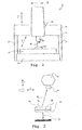
- the well-known and again in the Fig. 1 reproduced principle of a coordinate measuring machine 10 includes a z. B. granite base frame 12 with measuring table 14, on which an object to be measured 16 is positioned to measure its surface properties.
- a portal 18 is adjustable in the Y direction.
- columns or uprights 20, 22 are slidably supported on the base frame 12.
- a traverse 24 goes out, along which a carriage is movable, which in turn receives a quill or column 26 which is adjustable in the Z direction.
- a sensor 30 is made, which is formed in the embodiment as a tactile sensor, which when the sleeve 26 includes an image processing sensor, tactile-optically measures.
- the coordinate measuring machine 10 can have a sensor changer, as is the case in principle Fig. 2 can be seen.
- a plurality of sensors can each optionally be provided with the coordinate measuring machine via an exchange interface and exchanged by hand or by automatic retrieval of the coordinate measuring machine at a parking station.
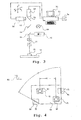
- Fig. 2 is a section of a coordinate measuring machine with a sleeve 32 reproduced in plan view.
- the sensors connectable to the quill are identified by the reference numerals 34, 36, 38.
- the sensors 34, 36, 38 may be designed optically or tactile, to name only sensor types.
- the coordinate measuring machine, ie the quill 32 is adjustable in the YXZ direction in order to carry out an exchange of the sensors 34, 36, 38.
- the parking station 42 or the Tasterwechslersystem can be adjusted by an adjustment axis 44 so that the probe changer 42 is arranged in non-operation outside the measuring volume of the coordinate measuring machine.
- the camera of the image processing sensor is selected with a larger resolution (number of pixels) than the resolution of the monitor used or of the monitor section used for the image display. Furthermore, the camera may have random access to certain Be part of the picture. It is then possible that in the live image or observation image of the coordinate measuring machine only a section of the overall image is displayed, which is enlarged to the format of the respective display window or monitor. As a result, the user has the option to select zoomed sections of the image according to his ideas.
- the magnification between the measurement object and the monitor image can be controlled by changing the selected section of the camera image by the software or the live image can be displayed in the same way.
- the magnification between the measurement object and the monitor image can be changed by changing the selected section of the camera image.
- This can optionally be operated by a rotary knob, which is integrated in the control system of the coordinate measuring machine, or via a software controller. It is also possible that when using a high-resolution camera, the image or the image is displayed only in the lower resolution of the monitor, in the background, however, the full resolution of the camera for digital image processing is used to increase the accuracy.
- optical magnification of the imaging optics of the image processing here is relatively low (typically 1-fold, but at most 5-fold) and the representation of only a section of the high-resolution camera image on the lower-resolution monitor, the optical effect of higher magnification is achieved.
- Fig. 3 is a section of a coordinate measuring machine arranged.
- the object to be measured 16 is shown on the measuring table 12.
- an imaging lens 46 and a camera such as CCD camera 48 are arranged, which is connected via a computer 50 to a monitor 52.
- the hardware of the computer 50 or computer it is possible to adjust the resolution between the camera 48 and the monitor 52 computationally, for. B. to use a larger camera resolution than can be reproduced by the monitor 52.
- magnification can be adapted to the requirements of the application by changing the section.
- z As an electronic encoder connected to the computer 50 54 this is ergonomically operated. It can further be realized that the actual image evaluation in the computer 50 takes place with the full resolution of the captured camera image by the camera 48. As a typical magnification for the measuring objective 46 here comes a simple, but at most 5-fold magnification in question. A higher optical magnification is realized by the previously described resolution adjustment. By an additional arrangement of a mirror 56 and a further camera 58, it is possible to vary the triggering range even more. Switching also takes place via the computer 50. In this case, both cameras with different chip sizes can be used with the same number of pixels as well as with different pixel numbers with the same chip size or both combined. In addition, a laser distance sensor 60 may use the same optical path.
- the camera 58 is equipped with additional post-magnification optics 62 to define the magnification.
- the optical splitters or mirrors used in the beam path, which are used in the Fig. 3 are denoted by the reference numerals 56 and 64 are designed so that after the division all affected cameras 48, 58 and 60 sensors are equipped with the same light intensity. Via an additional optical divider 66 and a lighting device 68, an integrated bright field incident light is realized.
- an even higher-resolution camera image can be displayed by re-sampling from the respectively acquired camera image with the purpose of displaying an even higher magnification.
- additional pixels are determined by interpolation between real measured pixels.
- a problem with known coordinate measuring machines is that once created programs for measuring workpieces are subsequently changed or subsequently additional features are to be generated from the measurement results already obtained. This is not possible in the current state of the art, since the corresponding associated technology data are no longer available.
- the measurement points or video images or X-ray images measured with one or more sensors of the coordinate measuring machine and their associated position and other technology parameters such as set value of the illumination system used, light intensity or magnification of the lens used during the coordinate measuring machine Recorded recorded the measurement process and made available for later evaluation so.
- a measuring object 68 is to be measured with an image processing sensor.
- image sections 70, 72, 76, 78 image sections are shown, which are detected at different positions in the X, Y coordinate system 80 of the coordinate measuring machine on the measuring object 68.
- the image contents of the object sections captured at the respective positions are stored, in addition to the respectively associated image processing evaluation windows 82, 84, 86, 88 and the parameters stored thereon in the coordinate measuring machine such as magnification of the objective used, setting value of the used lighting system.
- the actual measurement of the image content and the linkage eg. As the measurement of an angle 90 or a distance 92, take place.
- an image is automatically composed of several parts which are automatically combined Users then presented as a measured image and made available for evaluation.
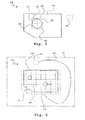
- a feature in the form of a bore 96 is to be measured on a measurement object 94.
- the field of view 98 of an image processing sensor is insufficient to fully capture this feature.
- the operator sets an evaluation area 100 that is significantly larger than the visual field 98.
- the software recognizes this automatically and in the exemplary embodiment defines four positions 102, 104, 106, 108 which are measured one after the other in order to combine an overall image and to measure the feature to be measured, ie the bore 96 in the exemplary embodiment.
- optionally located in the interior of the outer contour measuring points on the measurement object can be detected by screening with an image processing sensor and / or scanning with other sensors.
- a measurement object 110 lies on the measurement table 12.
- An image processing sensor used for the measurement has an evaluation region 112.
- the basic position of the measuring object 110 is detected on the measuring table 12 by changing the image content.
- an outer contour scanning of the measurement object 110 begins until complete detection of the outer contour along the path 118 (contour tracking). Thereafter, for complete detection of the total measuring object automatically a grid-shaped detection of the inner region of the Measured object 110 performed in the previously defined outer limits 120, so that then the total measurement object 118 is available for evaluation.
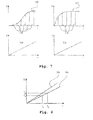
- the invention proposes that the characteristics of the illumination devices of the image processing sensor system of the coordinate measuring machine are recorded, d. H. the dependence of the illumination intensity on the adjustment image of the user interface of the measuring device is detected by measuring the intensity for the associated setting value with the image processing sensor system. Corresponding measurement results are stored as a characteristic curve in the computer of the measuring device. It is also possible to store the measured values in a so-called light box, which controls the illumination intensity during operation of the coordinate measuring machine.
- FIG. 7 So is in Fig. 7 at the top left, an original light characteristic 122 of an illumination system for an optical coordinate measuring machine is shown.
- the illumination intensity E hangs not linearly from the current flow I through the illumination source.
- the top right shows a similar, but in detail different characteristic 122 of a second coordinate measuring machine.
- Fig. 8 shows the procedure for controlling the light intensity E.
- a light characteristic 132 is effective.
- the setpoint value of the illumination intensity E s is set by the illumination current I 1 . If another measurement object or a different location of the measurement object is now measured, the reflection properties of the material may have changed, which leads to a change in the increase in the light characteristic. This second light characteristic 133 is also in Fig. 8 shown. If the illumination intensity is then measured after setting the current I 1 , the illuminance E 1 is determined as the result. This does not correspond to the setpoint E s . Since from I 1 and E 1, the increase of the now currently valid light characteristic is known, the necessary current I s can be calculated in a simple manner to set the target list strength E s .
- the physical structure for the process described above is the Fig. 2 can be seen in which the light source 68, the mirror 66 and the lens 46 represent the lighting device.
- the calculation takes place via the computer 50.
- the reflection behavior of the measurement object 16 is different within the measurement objects and generates the different response to current I and illumination intensity E.
- the length of contour sections corresponding to the nominal length while retaining the curvature or, alternatively, the contour curvature while maintaining the contour length on the profile will be inherent in the best fitting between the nominal and actual contour Actual contour changed so that an optimal coverage is achieved with the target contour. If parts with excellent geometric features are difficult to check by elasticity or deformation, this process can be assisted by fitting the actual and target contours to a group of actual and target contours on individually distinguished features, such as contours or contours Circular structures or other recurring structures takes place and so a distortion of the actual contour for optimum coverage with the target contour is generated.
- Fig. 9 should illustrate in principle that the actual contour for optimum coverage with the target contour in a cylinder-shell surface is partially twisted or screwed.
- Reference numeral 134 represents a point cloud, which is essentially represented by a cylindrical lateral surface. By delaying the measurement object, the structures on this cylindrical surface along the cylinder axis twisted or twisted. By the teaching of the invention, this distortion is compensated mathematically by turning back the structures in the starting position. This is realized by comparing the respective sections of the measuring point cloud transversely to the cylinder axis via a desired / actual comparison with corresponding desired data and from this the necessary twisting position for the respective section is calculated. This is then carried out for any number of cuts through the cylinder axis or between individual cuts interpolated the twist corrected.
- reference numeral 134 represents the measuring point cloud of a measuring object having a cylindrical shape.
- the measuring point cloud 134 is shown with distortion, wherein in the sections 136, 138, 140 each have a different degrees of twisting.
- a set point position 142 compared with an actual point position 144 and from this the angle of rotation 146 calculated.
- the corrected cutting planes are in Fig.
- Fig. 10 A shows an example of how, from an actual contour 156, by changing the curvature while maintaining the length, a better coverage to a desired contour 158 for the subsequent comparison can be produced therewith.
- Circle 160 represents that a better adaptation to the desired contour 158 is made possible by a change in curvature at a constant length (in this case circumference).
- Fig. 10b It is shown how, while maintaining the curvature of the contours by changing the length of contour sections, a better coverage between desired / actual value is made possible for the purpose of the later comparison. It is denoted by the reference numeral 162, the actual contour and the reference numeral 164 reproduce the desired contour.
- the contour 166 is the actual contour adapted by stretching while maintaining the curvature to the desired contour 164.
- the tolerance zones assigned to the desired or actual contour can be evaluated in the evaluation of the deviation between the nominal and actual contour.
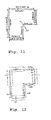
- the tolerance zones are automatically taken from the dimensional data of a CAD drawing or alternatively defined by operator information. Based on the explanations to the FIGS. 11 and 12 the procedure should be described in more detail.
- a workpiece 167 consisting of the elements 1 to 6 with associated dimensions (dimension 1 to dimension 4) and reproduced the tolerances associated with the dimensions.
- the corresponding dimensions and tolerances can be taken from a CAD drawing, but alternatively also be defined by operator input.
- a two-sided, symmetrical tolerance zone is allocated to all elements in the present example, which can have different widths per element. From the Fig. 11 It can be seen that the element 1 by measure 2 with respect to element 3 and by measure 4 with respect to element 5 two different width tolerance zones must be assigned. Analogously, the element 2 with respect to element 4 by specifying the dimension 3 and with respect to element 6 by specifying the measure 1 different tolerance zones assigned.
- the calculation and assignment of the different tolerance zones to the elements is carried out according to the invention automatically by analyzing all reference dimensions that are defined for an element within the drawing and by automatically subdividing the tolerance zones per drawing element according to the reference dimensions available for the element.
- the upper tolerance zone is created by the tolerance assigned to dimension 2; the lower tolerance zone is created by the tolerance assigned to dimension 4.
- the element 2 is assigned two tolerance zones, wherein the in Fig. 12 shown left tolerance zone for element 2 from the Dimension 1 assigned tolerance zone is formed, the right tolerance zone for element 2 by the dimension 3 associated tolerance zone arises.
- the measuring points recorded on the real workpiece 166 are assigned in a first step according to their position to one of the automatically determined tolerance zones.
- the measuring points associated with the respective tolerance zones are optimally fitted into the tolerances in the workpiece 166 defined by the nominal contour without binding degrees of freedom, wherein the fitting conditions are automatically selected depending on the type of tolerance.
- the corresponding check for tolerance zone evaluation is carried out sequentially for all tolerance zones and all measuring points assigned to these tolerance zones.
- the invention proposes that with the image processing sensor in autofocus mode for several evaluation areas simultaneously autofocus measurement points are generated at a plurality of semi-transparent layers. This is achieved by moving the image processing sensor in the measuring direction and simultaneously recording several images. The focus measuring points are calculated in the respectively determined evaluation ranges according to a contrast criterion.
- An image processing sensor 168 is moved to realize an auto-focus method corresponding to the Z-axis so that the focal point 170 of the sensor 168 is placed in different positions within the semi-transparent measurement object 172.
- a contrast characteristic 174 is recorded.
- Each maximum of the contrast characteristic represents the location of the respective semi-transparent boundary layer between different material layer types and from this contrast curve 174 the correspondingly assigned Z positions Z1, Z2 and Z3 can then be calculated.
- conventional methods for contrast auto focus measurement are used.
- contours are scanned on workpiece surfaces in the sensor direction, ie in one direction, different from the sensor measuring direction, the coordinate measuring machine is on a predetermined path emotional.
- the position control of the sensor or the position control loop of the coordinate measuring machine is controlled in dependence on the deflection display of the laser distance sensor so that the deflection of the laser distance sensor remains constant.
- a corresponding contour line scanning is based on the Fig. 14 clarified.
- a measuring object 176 is located on a measuring table of a coordinate measuring machine and is scanned with a distance sensor such as laser distance sensor 178 of the coordinate measuring machine.
- the laser distance sensor 178 is controlled in its movement so that the distance to the material surface is constant.
- the Z position of the sensor 178 is kept constant and achieved by regulating the X and Y position that the sensor measuring point always remains in a plane 180 and thus a contour line 182 is scanned on the measuring object 176.
- Coordinate measuring machines with various sensors also have, among other things, optionally sensors with an opto-tactile button.
- the determination of the position of the Antastformiatas (ball or cylinder) by an image processing sensor is to adjust this sensor to the position of the probe ball.
- This can be achieved by additionally arranging an adjustment unit on the coordinate axis bearing the sensor, which permits a relative adjustment between the probe form element (probe ball including stylus and holder) in the image processing sensor. For example, via an autofocus method, an automatic focusing of the detection element in relation to the image processing sensor is possible thereafter.
- a tactile-optical sensor 210 also called opto-tactile sensor
- a coordinate measuring machine on an adjustment axis 208, which is placed on a coordinate axis of the coordinate measuring machine, preferably the Z-axis 208, in the embodiment with the optical axis of an optical sensor 210th coincides.
- adjusting device 210 By separately controlling a second Z-axis (adjusting device 210), it is possible to selectively adjust the relative position between sensing element 212 of the tactile-optical sensor 206 to the focal plane 214 of the optical sensor 210.
- Coordinate measuring machines are generally exposed to different operating temperatures at the place of use. If several sensors are attached to the coordinate measuring machine, this will cause the positions between the different sensors to change thermally. This leads to measurement errors. To compensate for this, the temperature of the mechanical assemblies required for mounting the various sensors is measured at one or more locations and the expansion of the corresponding mechanical components is taken into account in the calculation of the measurement points detected by the various sensors.
- Fig. 17 an example of an arrangement with two sensors 218, 220 on a Z-axis 222 of a coordinate measuring machine.
- the sensors 218, 220 are one or more connecting elements 224 connected to each other and the Z-axis 222.
- a temperature sensor 226 By means of a temperature sensor 226, the temperature of the connecting element or elements 224 is measured continuously during the measurement, and the corresponding change in length is corrected by an evaluation computer 228 and taken into account for the measurement results.
- the measurement object In order to be able to measure a measurement object on a coordinate measuring machine from several sides during the measurement, it makes sense that the measurement object can be clamped in an axis of rotation and thus be screwed into an optimum position for the measurement with the various sensors. In addition to this, it is possible to record the measurement object in addition to the rotation axis itself with a correspondingly arranged counter-tip.
- the clamping force of the opposite tip can lead to deformations of the test object.
- the measured object is constantly deformed or the counter-tip is automatically positioned up to a predefined force on the measurement object. In this case, the counter-tip can be mounted sprung, so that via a deflection and a corresponding limit switch, the corresponding required force can be determined.
- Fig. 18 shows Fig. 18 in that when clamping a measuring object 230 tip 232 and counter tip 234 to a point through a guide 236 is pushed against the measuring object 230 until the counter-tip 234 interacts with a limit switch 238.
- a bias voltage by means of a biasing spring 240 are generated, wherein the feed movement (arrow 242) of the opposite tip 234, which is achieved by a corresponding drive 244 on the guide 236, then interrupted when the opposite tip 234 on the limit switch 238 or a gleichconcedes Element acts.
- the biasing force of the clamped measuring object 236 is clearly defined.
- a plurality of tactile sensors of similar or different construction are arranged close to each other on a common mechanical axis of the coordinate measuring machine.
- Fig. 19 shows an example.
- a plurality of tactile sensors 248, 250, 252 are arranged on a common Z-axis 254 of a coordinate measuring machine.
- measuring points 258, 260, 262 are simultaneously measured for different positions, which are then evaluated together in the coordinate measuring machine.
- a laser distance sensor is additionally integrated in the image processing beam path.
- the laser sensor measures the distance of the image processing sensor to the workpiece surface in the vicinity of the outer edge to be measured and is connected to a position control loop of the coordinate measuring machine in such a way that automatic tracking takes place.
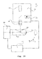
- the image processing sensor is thus permanently focused. This is based on the Fig. 20 explained in principle.
- On a Z-axis 258 of a coordinate measuring machine are two combined sensors 260, 262nd combined for image processing and laser distance measurement, which detect 264 measurement points on a tool 266 via a common optical system.
- the axis of rotation 268 of the tool 266 is controlled by a computer and control system 270 of the coordinate measuring machine, which also has the sensor signals of the CMM, so that measured by the laser distance sensor 262 measuring points on a rake face 272 of the tool 266 influence the settings of the rotation axis 268 so in that the cutting edge comes to rest here in each case in the section plane 274 of the tool.
- the image processing sensor 260 of the same coordinate measuring machine it is thereby possible to measure the outer contour of the corresponding tool. With constant turning and moving of the X, Y and Z axes of the CMM, this process can be repeated continuously, thus performing scanning in all three coordinates simultaneously.
- image processing sensors with laser sensors integrated in the beam path can be used.
- the desired optical properties for the integrated laser distance sensor and the image processing sensor will not be present at the same setting parameters (working distance / magnification).
- exchangeable optical attachment optics and aperture of the zoom optical system used can alternatively be optimized for the laser sensor and the image processing sensor.
- FIG. 21 an image processing sensor 276 and a laser distance sensor 278 are shown, which are inserted via a beam splitter 280 with a common measuring objective 282 in a coordinate measuring machine.
- a measurement object 284 is to be touched, that is to be measured without contact in the present case.
- the measuring points are usually specified by the operator in the teach-in mode. If unknown contours are to be measured in this method, this is only possible with difficulty.
- a scanning process of a material surface is performed with an autofocus sensor by theoretically calculating from the already measured focus points by extrapolation the prospective location of the next measurement point and measuring it accurately by a new autofocus point. If this process is repeated several times in succession, this results in a fully automatic scanning. In this case, both the number of points to be scanned along a line and an area to be scanned on the workpiece or measured object can be specified by the operator. The extrapolation of the next measurement point from the two or more preceding measurement points can be done by a linear extrapolation.
- FIG. 22 a corresponding method for scanning a material surface with an autofocus sensor.
- An autofocus sensor 290 is used in a first location 191 by movement in the Z-axis of the coordinate measuring machine to measure a surface point.
- the contrast behavior is recorded via a focus area 292 and from this the focus location 294 is calculated in accordance with the measurement point.
- the same process is repeated at a next position 295 with corresponding focus measuring range 296 and measuring point 298.
- z. B. interpolation of a line 300 the position of the focus measuring range 302 and thus the sensor 290 is defined in the position 304 and there a measuring point 306 measured. This process is repeated one after the other until the entire length of the contour 308 of the object to be measured or of a part thereof has been measured.
- the pixel amplitude of the X-ray detector 314 is stored in a computer and evaluation system 316 and evaluated according to previously explained method steps and joined together. In this case, it is possible to control the X-ray frequency of the radiation source 308 as well as the recording parameters of the detector 316 in accordance with the procedure described by the evaluation system 316.
Abstract
Description
Die Erfindung bezieht sich auf ein Koordinatenmessgerät zum Messen von Werkstückgeometrien mit beweglichen Verfahrachsen und einem oder mehreren Sensoren zur Erfassung von Messpunkten auf den Werkstückoberflächen. Auch nimmt die Erfindung Bezug auf ein Verfahren zum Messen von Werkstückgeometrien mit einem Koordinatenmessgerät mit beweglichen Verfahrachsen und einem oder mehreren Sensoren zur Erfassung von Messpunkten auf den Werkstückoberflächen.The invention relates to a coordinate measuring machine for measuring workpiece geometries with movable track axes and one or more sensors for detecting measuring points on the workpiece surfaces. The invention also relates to a method for measuring workpiece geometries with a coordinate measuring machine with movable track axes and one or more sensors for detecting measuring points on the workpiece surfaces.
Unter Koordinatenmessgeräten werden Messgeräte mit einer oder mehreren mechanisch bewegten Achsen zur Messung von geometrischen Eigenschaften von Werkstücken bzw. Messobjekten verstanden. Diese Koordinatenmessgeräte sind mit Sensoren zur Aufnahme der geometrischen Messpunkte an den Werkstückoberflächen ausgestattet. Stand der Technik sind überwiegend Koordinatenmessgeräte mit rein taktilen Sensoren, d. h. der Messpunkt wird durch Berührung der Werkstückoberfläche mit einem taktilen Fühler erzeugt. Ebenfalls bekannt sind Koordinatenmessgeräte mit optischen Sensoren, bei denen die Messpunkte durch eine opto-elektronische Bildverarbeitung oder ein Laserabstandssensor ermittelt werden. Es sind ebenfalls Koordinatenmessgeräte bekannt, bei denen einzelne dieser Sensoren miteinander kombiniert und so erweiterte Möglichkeiten für den Anwender gegeben sind.Coordinate measuring machines are understood to mean measuring devices with one or more mechanically moved axes for measuring geometric properties of workpieces or measuring objects. These coordinate measuring machines are equipped with sensors for recording the geometrical measuring points on the workpiece surfaces. Prior art are predominantly coordinate measuring machines with purely tactile sensors, d. H. the measuring point is generated by touching the workpiece surface with a tactile probe. Also known are coordinate measuring machines with optical sensors, in which the measuring points are determined by an optoelectronic image processing or a laser distance sensor. Coordinate measuring machines are also known in which individual ones of these sensors are combined with one another and thus extended possibilities for the user are given.
Einen Überblick über die Koordinatenmesstechnik ergibt sich aus den Literaturstellen DE.Z.:
Immer wieder ist es festzustellen, dass das zum Einsatz gelangende Koordinatenmessgerät für die jeweilige Messaufgabe nicht optimal konfiguriert ist, so dass folglich mehrere Geräte verschiedener Bauarten notwendig sind.Again and again it should be noted that the coordinate measuring machine used for the respective measuring task is not optimally configured, so that consequently several devices of different types are necessary.
Der vorliegenden Erfindung liegt die Aufgabe zugrunde, mit einem Koordinatenmessgerät präzise Messen zu können und eine Vereinfachung von Messroutinen zu ermöglichen. Auch soll die Möglichkeit gegeben sein, einmal erzeugte Programme zum Messen von Werkstücken nachträglich zu ändern oder nachträglich aus bereits gewonnenen Messergebnissen zusätzliche Merkmale zu generieren.The object of the present invention is to be able to measure precisely with a coordinate measuring machine and to facilitate a simplification of measuring routines. Also, the possibility should be given to once created programs for measuring workpieces to subsequently change or subsequently generate additional features from already obtained measurement results.
Verfahrensmäßig wird die Aufgabe im Wesentlichen dadurch gelöst, dass die mit einem oder mehreren Sensoren des Koordinatenmessgerätes aufgenommenen Messpunkte sowie die zugehörigen Positionen und andere Technologieparameter des Koordinatenmessgerätes aufgenommen und gespeichert und für eine spätere Auswertung zur Verfügung gestellt werden.In terms of the method, the object is essentially achieved by recording and storing the measuring points recorded with one or more sensors of the coordinate measuring machine as well as the associated positions and other technology parameters of the coordinate measuring machine and making them available for later evaluation.
Vorrichtungsmäßig wird ein Koordinatenmessgerät zum Messen von Werkstückgeometrien mit beweglichen Verfahrachsen und einem oder mehreren Sensoren zur Erfassung von Messpunkten auf den Werkstückoberflächen vorgeschlagen, das sich dadurch auszeichnet, dass ein Sensor ein Bildverarbeitungssensor ist und dass für den Bildverarbeitungssensor eine Kamera mit einer höheren Auflösung als Standard-Video-Norm, z.B. 1200x600 Pixel, einsetzbar ist, das Kamerabild auf dem Rechnermonitor mit einer Grafikkarte oder Grafikeinstellung geringerer Auflösung anzeigbar ist und im Hintergrund ein Bildverarbeitungsrechner mit einem zugeordneten Bildspeicher entsprechend der vollen Größe der hochauflösenden Kamera zur digitalen Bildverarbeitung einsetzbar ist.Device-wise, a coordinate measuring machine for measuring workpiece geometries with movable track axes and one or more sensors for detecting measuring points on the workpiece surfaces is proposed, which is characterized in that a sensor is an image processing sensor and that for the image processing sensor a camera with a higher resolution than standard Video standard, eg 1200x600 pixels, can be used, the camera image on the computer monitor with a graphics card or graphic setting lower resolution is displayed and in the background an image processing computer with an associated image memory according to the full size of the high-resolution camera for digital image processing is used.
Ausgestaltungen ergeben sich aus den jeweiligen abhängigen Ansprüchen.Embodiments emerge from the respective dependent claims.
Auch liegt der vorliegenden Erfindung das Problem zu Grunde, ein Koordinatenmessgerät sowie ein Verfahren zum Messen von Werkstückgeometrien mit einem Koordinatenmessgerät derart weiterzubilden, dass eine optimale Konfigurierung für die jeweilige Messaufgabe gegeben ist, so dass grundsätzlich mehrere Geräte verschiedener Bauart nicht notwendig sind.The present invention is also based on the problem of developing a coordinate measuring machine and a method for measuring workpiece geometries with a coordinate measuring machine in such a way that an optimal configuration for the respective Measuring task is given, so that basically several devices of different types are not necessary.
Die Aufgabe wird erfindungsgemäß dadurch gelöst, dass ein Koordinatenmessgerät mit allen für die Lösung der Messaufgabe erforderlichen Sensoren ausgestattet ist. Diese können wahlweise montiert oder demontiert werden oder über entsprechende Sensorwechselsysteme auch während des Betriebes automatisch ein- und ausgewechselt werden. Hiermit ist ein flexibles Messen komplexer Werkstückgeometrien möglich. Es ist selbstverständlich ebenfalls möglich eine entsprechende Anzahl von ausgewählten Sensoren fest auf dem Gerät montiert zu lassen und in dieser Konfiguration die Werkstücke zu messen.The object is achieved in that a coordinate measuring machine is equipped with all necessary for the solution of the measurement task sensors. These can either be mounted or disassembled or automatically switched on and replaced by appropriate sensor change systems during operation. This allows a flexible measurement of complex workpiece geometries. Of course, it is also possible to have a corresponding number of selected sensors permanently mounted on the device and to measure the workpieces in this configuration.
Es wird ein Koordinatenmessgerät zum Messen von Werkstückgeometrien mit beweglichen Verfahrachsen und einem oder mehreren Sensoren zur Erfassung von Messpunkten auf den Werkstückoberflächen vorgeschlagen, wobei als Sensor eine Bildverarbeitungssensorik und/oder ein schaltendes Tastsystem und/oder ein messendes Tastsystem und/oder ein in die Bildverarbeitungssensorik integrierter Laserabstandssensor und/oder ein separater Laserabstandssensor und/oder ein Weißlichtinterferometer und/oder ein taktil optischer Taster, bei dem die Lage des Antastformelementes direkt durch einen Bildverarbeitungssensor bestimmt wird, und/oder ein punktförmig arbeitender Interferometersensor und/oder ein punktförmig arbeitender Interferometersensor mit integrierter Rotationsachse und/oder ein punktförmig arbeitender Interferometersensor mit abgewinkelter Blickrichtung, und/oder eine Röntgensensorik und/oder ein chromatischer Fokussensor und/oder ein Konfokal Scanning-Messkopf montiert sind. Dabei wird Art bzw. Anzahl der zum Einsatz gelangenden Sensoren auf die jeweilige Messaufgabe ausgelegt.A coordinate measuring machine for measuring workpiece geometries with movable track axes and one or more sensors for detecting measuring points on the workpiece surfaces is proposed, wherein the sensor is an image processing sensor system and / or a switching touch probe and / or a measuring touch probe and / or an image sensor integrated in the image processing sensor Laser distance sensor and / or a separate laser distance sensor and / or a white light interferometer and / or a tactile optical probe, in which the position of the sensing element is determined directly by an image processing sensor, and / or a punctiform interferometer sensor and / or a punctiform interferometer sensor with integrated rotation axis and / or a point-type interferometer sensor with angled viewing direction, and / or an X-ray sensor system and / or a chromatic focus sensor and / or a confocal scanning measuring head are mounted. In this case, the type or number of sensors used is designed for the respective measuring task.
Entsprechend zeichnet sich ein Verfahren zum Messen von Werkstückgeometrien mit einem Koordinatenmessgerät mit beweglichen Verfahrachsen und einem oder mehreren Sensoren zur Erfassung von Messpunkten auf den Werkstückoberflächen dadurch aus, dass als Sensor eine Bildverarbeitungssensorik und/oder ein schaltendes Tastsystem und/oder ein messendes Tastsystem und/oder ein in die Bildverarbeitungssensorik integrierter Laserabstandssensor und/oder ein separater Laserabstandssensor und/oder ein Weißlichtinterferometer und/oder ein taktil optischer Taster, bei dem die Lage des Antastformelementes direkt durch einen Bildverarbeitungssensor bestimmt wird, und/oder einen punktförmig arbeitender Interferometersensor und/oder einen punktförmig arbeitender Interferometersensor mit integrierter Rotationsachse und/oder ein punktförmig arbeitender Interferometersensor mit abgewinkelter Blickrichtung und/oder einer Röntgensensorik und/oder ein chromatischer Fokussensor und/oder ein Konfokal Scanning-Messkopf eingesetzt werden, wobei Art und Anzahl der verwendeten Sensoren auf die jeweilige Messaufgabe ausgerichtet ausgewählt wird.Accordingly, a method for measuring workpiece geometries with a coordinate measuring machine with movable track axes and one or more sensors for detecting measuring points on the workpiece surfaces is characterized in that the sensor is an image processing sensor and / or a switching touch probe and / or a measuring touch probe and / or an integrated in the image processing sensor Laser distance sensor and / or a separate laser distance sensor and / or a white light interferometer and / or a tactile optical probe, in which the position of the Antastformelementes is determined directly by an image processing sensor, and / or a punctiform interferometer sensor and / or a punctiform interferometer sensor with integrated rotation axis and / or a point-type interferometer sensor with angled viewing direction and / or an X-ray sensor system and / or a chromatic focus sensor and / or a confocal scanning measuring head are used, wherein the type and number of sensors used is selected aligned to the respective measurement task.
Über das oben beschriebene Grundproblem hinaus ergeben sich weitere Detailprobleme beim Aufbau eines solchen Koordinatenmessgerätes. Diese sollen im Nachfolgenden beschrieben und dafür Lösungen aufgezeigt werden.In addition to the basic problem described above, further detail problems arise in the construction of such a coordinate measuring machine. These will be described below and solutions shown.
Bei der Anwendung von Bildverarbeitungssensoren in Koordinatenmessgeräten ist es für den Anwender erforderlich, verschiedene Vergrößerungen einzustellen. Dem widerspricht die Forderung nach kostenoptimierten optischen Systemen sowie hohen Abbildungsgüten, die mit den sonst erforderlichen Zoom-Optiken nur schwer zu erreichen sind. In einem die Erfindung selbständig weiterführenden Gedanken kann dies dadurch gelöst werden, dass die Kamera des Bildverarbeitungssensors mit einer größeren Auflösung (Pixelanzahl) gewählt wird, als die Auflösung des verwendeten Monitors bzw. des für die Bilddarstellung verwendeten Monitorsausschnitts. Im Weiteren kann die Kamera mit wahlfreiem Zugriff auf bestimmte Ausschnitte des Gesamtbildes ausgestattet sein. Es ist dann möglich, dass im Live-Bild oder Beobachtungsbild des Koordinatenmessgerätes nur ein Ausschnitt des Gesamtbildes dargestellt wird, der auf das Format des jeweiligen Anzeigefensters bzw. Monitors vergrößert wird. Im Ergebnis hat der Anwender die Möglichkeit, gezoomte Ausschnitte des Bildes entsprechend seinen Vorstellungen auszuwählen. Die Vergrößerung zwischen Messobjekt und Monitorbild kann durch Verändern des gewählten Ausschnittes des Kamerabildes durch die Software gesteuert werden oder auch das Live-Bild in gleicher Weise dargestellt werden. Die Vergrößerung zwischen Messobjekt und Monitorbild kann durch Verändern des gewählten Ausschnittes des Kamerabildes verändert werden. Dies kann gegebenenfalls durch einen Drehknopf, der in das Steuerungssystem des Koordinatenmessgerätes integriert ist, oder über einen Softwareregler bedient werden. Es ist fernerhin möglich, dass bei Einsatz einer hochauflösenden Kamera das Bild bzw. der Bildausschnitt nur in der geringeren Auflösung des Monitors angezeigt wird, im Hintergrund jedoch die volle Auflösung der Kamera zur digitalen Bildverarbeitung eingesetzt wird, um die Genauigkeit zu steigern. Die wirkliche optische Vergrößerung der Abbildungsoptik der Bildverarbeitung ist hierbei relativ gering (typisch 1-fach, höchstens jedoch 5-fach) und durch die Darstellung lediglich eines Ausschnittes des hoch auflösenden Kamerabildes auf dem geringer auflösenden Monitor wird die optische Wirkung einer höheren Vergrößerung erreicht.When using vision sensors in coordinate measuring machines, it is necessary for the user to set different magnifications. This contradicts the demand for cost-optimized optical systems and high imaging qualities, which are difficult to achieve with the otherwise required zoom optics. In a thought independently proceeding the invention this can be solved by selecting the camera of the image processing sensor with a larger resolution (number of pixels) than the resolution of the monitor used or the monitor section used for the image display. Furthermore, the camera can be equipped with random access to certain sections of the overall picture. It is then possible that in the live image or observation image of the coordinate measuring machine only a section of the overall image is displayed, which is enlarged to the format of the respective display window or monitor. As a result, the user has the opportunity to select zoomed sections of the image according to his ideas. The magnification between the measurement object and the monitor image can be controlled by changing the selected section of the camera image by the software or the live image can be displayed in the same way. The magnification between the measurement object and the monitor image can be changed by changing the selected section of the camera image. This can be done by a Rotary knob, which is integrated in the control system of the coordinate measuring machine, or operated by a software controller. It is also possible that when using a high-resolution camera, the image or the image is displayed only in the lower resolution of the monitor, in the background, however, the full resolution of the camera for digital image processing is used to increase the accuracy. The actual optical magnification of the imaging optics of the image processing here is relatively low (typically 1-fold, but at most 5-fold) and the representation of only a section of the high-resolution camera image on the lower-resolution monitor, the optical effect of higher magnification is achieved.
Eine Erweiterung der oben beschriebenen Vorgehensweise besteht darin, dass in einem optischen Strahlengang mehrere, jedoch mindestens 2 Kameras über Spiegelsysteme integriert sind und das gleiche Abbildungsobjektiv nutzen. Zusätzlich kann ein Laserabstandssensor integriert sein und ebenfalls das gleiche Abbildungsobjektiv genutzt werden. Es ist somit möglich, durch Wahl verschiedener Schnittweiten oder verschiedener Kameras mit verschiedener Chipgröße bei gleicher Pixelzahl oder mit verschiedener Pixelanzahl bei gleicher Chipgröße oder beidem verschiedene Vergrößerungen für den Anwender zu realisieren. Es ist ebenfalls möglich, hier zusätzlich einen Laserabstandssensor in den Strahlengang zu integrieren, der über Spiegelsysteme ebenfalls das gleiche Abbildungsobjektiv nutzt. Reichen die durch Auswahl verschiedener Kamerachips gegebenen Vergrößerungsbereiche noch nicht aus, ist es möglich zusätzlich vor jede Kamera im Kamerastrahlengang eine entsprechende Nachvergrößerung oder Nachverkleinerung als optisches Bauelement zu integrieren.An extension of the procedure described above is that several but at least two cameras are integrated via mirror systems in an optical beam path and use the same imaging objective. In addition, a laser distance sensor can be integrated and also the same imaging lens can be used. It is thus possible to realize different magnifications for the user by choosing different cutting widths or different cameras with different chip size with the same number of pixels or with different number of pixels with the same chip size or both. It is also possible here to additionally integrate a laser distance sensor in the beam path, which also uses the same imaging objective via mirror systems. If the magnification ranges given by selection of different camera chips are not sufficient, it is possible to additionally integrate a corresponding after-magnification or redimensioning as an optical component in front of each camera in the camera beam path.
Um zu vermeiden, dass bei einheitlicher Beleuchtung des Messobjektes auf den verschiedenen Kameras unterschiedliche Beleuchtungsintensitäten auftreten, die zu Schwierigkeiten bei der Bildauswertung führen, sind die optischen Teiler (z. B. Spiegel), die die Strahlengänge für die verschiedenen Kameras aufteilen, so gestaltet, dass alle Kameras die gleiche anteilige Lichtintensität erhalten. Dies wird über Auswahl entsprechender Reflexions- bzw. Transmissionsgrade der verwendeten optischen Teiler, insbesondere Teilerspiegel erreicht. Zusätzlich kann dieses System ebenfalls durch einen integrierten Hellfeldauflichtstrahlengang erweitert werden. Dieser Hellfeldauflichtstrahlengang wird ebenfalls über einen entsprechend dimensionierten optischen Teiler wie Teilerspiegel realisiert.In order to avoid that different illumination intensities occur on the different cameras when the measured object is uniformly illuminated, which leads to difficulties in image evaluation, the optical splitters (for example mirrors) which divide the beam paths for the different cameras are designed such that that all cameras receive the same proportionate light intensity. This is achieved by selecting appropriate reflectance or transmittance of the optical splitters used, in particular splitter levels. In addition, this system can also be extended by an integrated bright field light beam path. This brightfield reflected light beam path is also realized via a correspondingly dimensioned optical divider as splitter mirror.
Ein besonderes Problem besteht noch darin, dass die gewählte Anzeigeauflösung kein ganzzahliges Vielfaches oder ganzzahliger Teiler der gewählten Bildaufnahmeauflösung ist. Eine Anpassung bei der Auflösung aneinander kann durch Re-sampling aus dem mit einer hochauflösenden Kamera aufgenommenen Bild erfolgen. Es wird eine entsprechende der Auflösung des Auswerte- bzw. Anzeigebereichs erforderliche Anzahl der Bildpunkte errechnet.A particular problem is that the selected display resolution is not an integer multiple or integer divisor of the selected image capture resolution. An adaptation in the resolution to each other can be done by re-sampling from the captured with a high-resolution camera image. A corresponding number of pixels required for the resolution of the evaluation or display area is calculated.
Ein weiteres Problem beim Einsatz bekannter Koordinatenmessgeräte besteht darin, dass einmal erzeugte Programme zum Messen von Werkstücken nachträglich geändert bzw. nachträglich zusätzliche Merkmale aus den bereits gewonnenen Messergebnissen generiert werden sollen. Dies ist nach dem gegenwärtigen Stand der Technik nicht möglich, da die entsprechenden zugehörigen Technologiedaten nicht mehr vorhanden sind. Eigenerfinderisch wird das Problem dadurch gelöst, dass die mit einem oder mehreren Sensoren des Koordinatenmessgerätes gemessenen Messpunkte bzw. Video-Bilder bzw. Röntgenbilder sowie deren zugehörige Position und andere Technologieparameter wie Einstellwert des verwendeten Beleuchtungssystems, Lichtintensität etc. des Koordinatenmessgerätes während des Messablaufs aufgenommen und abgespeichert und für eine spätere Auswertung so zur Verfügung gestellt werden. Analog zu dieser beschriebenen Vorgehensweise ist es ebenfalls möglich, dass mit dem Bildverarbeitungssensor mehrere Teilbilder eines Messobjektes einzeln gemessen und zu einem Gesamtbild des Gesamtmessobjektes oder zu einem Gesamtbild von Teilbereichen des gesamten Messobjektes zusammengefügt werden. Dieses Bild kann gespeichert werden und später auf einem separaten Arbeitsplatz ausgewertet werden. Hierzu werden ebenfalls die Kalibrierparameter des zur Bildaufnahme eingesetzten Koordinatenmessgerätes mitgespeichert und bei der Auswertesoftware erneut eingesetzt. Ein Offline-Rasterscanning wird ermöglicht.Another problem with the use of known coordinate measuring machines is that once generated programs for measuring workpieces subsequently changed or subsequently additional features are to be generated from the measurement results already obtained. This is not possible in the current state of the art because the corresponding associated technology data is no longer available. Autonomously, the problem is solved by the measured with one or more sensors of the coordinate measuring measuring points or video images or X-ray images and their associated position and other technology parameters such as set value of the illumination system used, light intensity, etc. of the coordinate measuring device during the measurement process and stored and be made available for later evaluation. Analogously to this described procedure, it is also possible that with the image processing sensor a plurality of partial images of a measurement object are individually measured and combined to form an overall image of the total measurement object or to an overall image of partial areas of the entire measurement object. This image can be saved and later evaluated on a separate workstation. For this purpose, the calibration parameters of the coordinate measuring machine used for image recording are also stored and used again in the evaluation software. Offline raster scanning is enabled.
In Abwandlung der oben beschriebenen Vorgehensweise ist es ebenfalls möglich, dass der gesamte Messablauf inklusive Fahrposition des Koordinatenmessgerätes und/oder den Bildern des Bildverarbeitungssensors und/oder den Bildern des Röntgensensors und/oder den Tastpunkten des taktilen Sensors und/oder den Tastpunkten des Lasersensors und/oder weiteren Technologieparametern abgespeichert und so einer späteren Auswertung zur Verfügung gestellt werden. Während der späteren Auswertung können sowohl neue Messergebnisse aus den vorhandenen Messpunkten und Technologieparametern generiert werden, als auch unter Einbeziehung des Messgerätes direkt am Messgerät überprüft werden als auch die eigentlichen Messprogramme für die Anwendung an weiteren Messobjekten optimiert und verändert werden.In a modification of the procedure described above, it is also possible that the entire measurement process including driving position of the coordinate measuring machine and / or the images of the image processing sensor and / or the images of the X-ray sensor and / or the tactile points of the tactile sensor and / or the scanning of the laser sensor and / or other technology parameters are stored and so provided for a later evaluation. During the later evaluation, both new measurement results from the existing measurement points and technology parameters can be generated, as well as checked by the measuring device directly on the measuring device as well as the actual measuring programs for the application to further measurement objects can be optimized and changed.
Es ist vorgesehen, dass bei Einsatz des Bildverarbeitungssensors für den Fall, dass das Sehfeld der Kamera nicht ausreicht, um das durch Wählen des gewünschten Auswertebereiches (Bildverarbeitungsfenster) definierte Areal des Messobjektes auf einmal zu erfassen, automatisch ein Bild aus mehreren Teilbildern zusammengesetzt wird und dem Anwender anschließend wie ein gemessenes Bild dargestellt und zur Auswertung zur Verfügung gestellt wird.It is provided that when using the image processing sensor in the event that the field of view of the camera is not sufficient to capture the defined by selecting the desired evaluation area (image processing window) area of the measurement object at once, an image is composed of several sub-images and the Users then presented as a measured image and made available for evaluation.
Ein häufig auftretendes Problem besteht darin, dass Geräte von weniger geschulten Bedienern bedient werden sollen. Hier sollen nach Idealvorstellung die Messobjekte einfach auf dem Koordinatenmessgerät aufgelegt und ein Startknopf gedrückt werden. Das Problem besteht darin, dass dem Koordinatenmessgerät zu Anfang gezeigt werden muss, wo das eigentliche Messobjekt liegt, um das CNC-Programm in den Werkstückkoordinaten des Koordinatenmessgerätes ausführen zu können. Selbständig erfinderisch wird hierzu folgendes Verfahren vorgeschlagen: Nach Auflegen des Werkstücks auf das Koordinatenmessgerät erfolgt ein Suchen des Messobjektes im Messbereich des Koordinatenmessgerätes durch Fahren eines Sensors, insbesondere eines Bildverarbeitungssensors auf einem geradlinigen, spiralförmigen, mäanderförmigen, kreisbogenförmigen, stochastischen oder anders gearteten Suchweg, bis die Existenz eines Messobjektes detektiert wird.A common problem is that devices should be operated by less trained operators. Here, after the ideal presentation, the measurement objects are simply placed on the coordinate measuring machine and a start button is pressed. The problem is that the coordinate measuring machine must first be shown where the actual measuring object is in order to be able to execute the CNC program in the workpiece coordinates of the coordinate measuring machine. After the workpiece has been placed on the coordinate measuring machine, the measuring object is searched for in the measuring range of the coordinate measuring machine by driving a sensor, in particular an image processing sensor on a straight, spiral, meandering, circular arc, stochastic or other kind of search path, until the Existence of a measured object is detected.
In einem zweiten Verfahrensschritt folgt ein Scanning der Außenkontur beginnend an dem durch Detektieren des Messobjektes generierten Startpunkt (Konturverfolgung zur Erfassung der Außengeometrie und Lage des Messobjektes).In a second method step, a scanning of the outer contour follows, starting at the starting point generated by detecting the measurement object (contour tracking for detecting the outer geometry and position of the measurement object).
In einem dritten Verfahrensschritt erfolgt optional das Erfassen der innerhalb dieser Außenkontur liegenden Messpunkte durch Einsatz eines der wahlweise verfügbaren Sensoren des Koordinatenmessgerätes, zum Beispiel durch Rastern mit dem Bildverarbeitungssensor oder Abtasten mit dem taktilen Sensor. Die so gewonnen Messpunkte können dann der weiteren Auswertung entsprechend einem Prüfplan zugeführt werden. Es ist ebenfalls möglich, anschließend Regelgeometrieelemente bereits innerhalb der bekannten Werkstücklage zu messen oder die ersten gemessenen Konturpunkte lediglich zur Ausrichtung des Werkstücks in Werkstückkoordinaten zu nutzen und anschließend Regelgeometrieelemente und Merkmale wie Winkel und Abstände zu messen.In a third method step, the measuring points located within this outer contour are optionally detected by using one of the optionally available sensors of the coordinate measuring machine, for example by scanning with the image processing sensor or by scanning with the tactile sensor. The measuring points thus obtained can then be fed to the further evaluation in accordance with a test plan. It is also possible to subsequently measure rule geometry elements already within the known workpiece position or to use the first measured contour points merely for aligning the workpiece in workpiece coordinates and then to measure rule geometry elements and features such as angles and distances.
Ein weiteres Problem beim Einsatz von Koordinatenmessgeräten, insbesondere bei solchen mit Bildverarbeitungssensoren, besteht darin, dass die verschiedenen Beleuchtungsquellen nichtlineare Kennlinien aufweisen, d. h. der an der Computersoftware angezeigte Einstellwert der Beleuchtungsintensität ist nicht mit einem linearen Zusammenhang mit der wirklichen Beleuchtungsintensität des Beleuchtungssystems verbunden. Dies führt unter anderem dazu, dass verschiedene Messobjekte nicht richtig gemessen werden können oder Programme von einem auf das andere Gerät nicht ohne Weiteres übertragbar sind. Eigenerfinderisch wird zur Lösung des Problems vorgeschlagen, dass die Kennlinien der Beleuchtungseinrichtungen des Bildverarbeitungssensorsystems des Koordinatenmessgerätes aufgenommen werden, d. h. es wird die Abhängigkeit der Beleuchtungsintensität vom Einstellwerte der Bedieneroberfläche des Messgerätes durch Messen der Intensität zum zugehörigen Einstellwert mit der Bildverarbeitungssensorik erfasst. Die entsprechenden Messergebnisse werden als Kennlinie im Rechner des Messgerätes gespeichert. Alternativ ist es ebenfalls möglich, diese Messwerte in einer sogenannten Lichtbox zu speichern, die die Steuerung der Beleuchtungsintensität im Betrieb des Koordinatenmessgerätes vornimmt. Führt man diese Lichtkennlinienmessung an einem kalibrierten Referenzobjekt oder zumindest für mehrere Geräte an einem einheitlichen Kalibrierobjekt durch, wird es hierdurch möglich, die Geräte in ihrem Verhalten nach außen hin, d. h., in ihrem Verhalten bezüglich Abhängigkeit Einstellwert Licht - physikalischer Beleuchtungswert anzugleichen und somit die Programmübertragbarkeit von verschiedenen Geräten sicherzustellen. Um die Bedienung der Geräte zu erleichtern ist es sinnvoll, die Kennlinie so zu korrigieren, dass für den Bediener eine Linearität vorherrscht, d. h. dass im Betrieb des Koordinatenmessgerätes die vorher eingemessene Kennlinie so für die Korrekturrechnung berücksichtigt wird, dass scheinbar eine lineare Kennlinie für den Bediener vorliegt, d. h. der Einstellwert und die Beleuchtungsintensität folgen dann einem linearen Zusammenhang. Der Anstieg dieser linearen Kennlinie kann dann für mehrere Geräte durch einen einfachen Korrekturfaktor angeglichen werden.Another problem with the use of coordinate measuring machines, in particular those with image processing sensors, is that the different lighting sources have non-linear characteristics, ie the setting of the illumination intensity displayed on the computer software is not associated with a linear relationship with the actual illumination intensity of the lighting system. Among other things, this leads to the fact that different measurement objects can not be measured correctly or programs from one to the other device are not readily transferable. It is self-inventively proposed to solve the problem that the characteristic curves of the illumination devices of the image processing sensor system of the coordinate measuring machine are recorded, ie the dependence of the illumination intensity on the setting values of the user interface of the measuring device is detected by measuring the intensity to the associated setting value with the image processing sensor system. The corresponding measurement results are stored as a characteristic in the computer of the measuring device. Alternatively, it is also possible to store these measured values in a so-called light box, which performs the control of the illumination intensity in the operation of the coordinate measuring machine. If one carries out this light characteristic measurement on a calibrated reference object or at least for several devices on a uniform calibration object, this makes it possible to adapt the devices in their behavior towards the outside, ie in their behavior with respect to the setting value light-physical illumination value and thus the program portability of different devices. To the operation To facilitate the devices, it is useful to correct the characteristic so that the operator dominates a linearity, ie that during operation of the coordinate measuring the previously measured characteristic is taken into account for the correction calculation, that apparently a linear characteristic for the operator is present the setting value and the illumination intensity then follow a linear relationship. The slope of this linear characteristic can then be adjusted for several devices by a simple correction factor.
Aufbauend auf der oben beschriebenen Linearisierung von Beleuchtungseinrichtungskennlinien in Koordinatenmessgeräten ist es möglich, das Problem zu lösen, dass verschieden helle Messobjekte nicht so ohne Weiteres mit der gleichen Beleuchtungseinstellung gemessen werden können, da die Ausleuchtung des Messobjektes nicht ordnungsgemäß gegeben ist. Erfindungsgemäß wird dies dadurch gelöst, dass nach folgenden Verfahrensschritten vorgegangen wird:Based on the above-described linearization of illumination device characteristics in coordinate measuring machines, it is possible to solve the problem that differently bright measurement objects can not be easily measured with the same illumination setting, since the illumination of the measurement object is not given properly. According to the invention, this is achieved by proceeding according to the following method steps:
Beim Abarbeiten von Automatikprogrammen für das Messen von Teilen mit verschiedener Reflexionsintensität werden zuerst die im Programm vorgegebenen Einstellwerte für die Beleuchtungsintensitäten der verschiedenen Beleuchtungsquellen eingestellt. In einem zweiten Schritt wird die Beleuchtungsintensität, die durch das Reflexionsverhalten des Werkstücks beeinflusst wird, mit dem Bildverarbeitungssensor überprüft und kontrolliert, ob der Messwert dem gespeicherten Sollwert bzw. Einstellwert entspricht. Überschreitet die Abweichung zwischen Soll- und Istwert einen festgelegten Grenzbetrag, wird der Einstellwert der Beleuchtungsintensität linear entsprechend der vorher erfassten Lichtkennlinie des Beleuchtungssystems korrigiert und neu eingestellt. Hieraus resultiert, dass der gewünschte Intensitätswert, wie im Programm hinterlegt, vom Messobjekt reflektiert wird. Anschließend wird das gewünschte Objektmerkmal gemessen. Dieser Vorgang wird entsprechend der Anzahl der Bildausschnitte, die das Koordinatenmessgerät für die Lösung der Messaufgabe benötigt, wiederholt. Der Vorteil dieser Vorgehensweise gegenüber herkömmlichen Lichtregelsystemen besteht darin, dass zu diesem Regelverfahren lediglich 2 Bilder des Messobjektes aufgenommen werden müssen und somit eine sehr schnelle Lichtregelung realisierbar ist.When executing automatic programs for measuring parts with different reflection intensity, the set values for the illumination intensities of the different illumination sources specified in the program are set first. In a second step, the illumination intensity, which is influenced by the reflection behavior of the workpiece, checked with the image processing sensor and checks whether the measured value corresponds to the stored setpoint or set value. If the deviation between the setpoint and the actual value exceeds a fixed limit amount, the setting value of the illumination intensity is linearly corrected and readjusted in accordance with the previously detected light characteristic of the illumination system. The result of this is that the desired intensity value, as stored in the program, is reflected by the measurement object. Then the desired object feature is measured. This process is repeated according to the number of image sections that the coordinate measuring machine requires to solve the measuring task. The advantage of this approach over conventional light control systems is that only 2 images of the measurement object must be recorded for this control method and thus a very fast light control can be realized.
Nach der oben beschriebenen Verfahrensweise ist es ebenfalls möglich, mehrere Kennliniensätze für das Koordinatenmessgerät zu hinterlegen, die dem Verhalten von weiteren ähnlichen Koordinatenmessgeräten mit jedoch unterschiedlichen Lichtkennlinien entsprechen. Somit können auch Messprogramme von älteren oder Fremdherstellern genutzt werden.According to the procedure described above, it is also possible to deposit a plurality of characteristic sets for the coordinate measuring machine, which correspond to the behavior of other similar coordinate measuring machines with, however, different light characteristics. This means that measuring programs from older or third-party manufacturers can also be used.
Mit Koordinatenmessgeräten ist es möglich, Konturen auf Werkstückflächen zu scannen. Dies kann sowohl mit einem Sensor oder auch bei kombiniertem Betrieb mit mehreren Sensoren realisiert werden. Erfolgt eine Auswertung der Konturen durch Vergleich mit Sollkonturen aus z. B. CAD-Files, ist es erforderlich Soll- und Ist-Rechner intern übereinander zu legen, um einen grafischen Vergleich zu realisieren. Insbesondere bei flexiblen oder biegsamen Teilen ist dies durch einfaches Verschieben der Relativlage oder Verdrehen der Relativlage nicht möglich, da die Teile elastisch verformt sind. Durch Vorgehen nach der wie folgt beschriebenen eigenerfinderischen Gehalt aufweisenden Methode, wird dieses Problem gelöst. Es werden bei der Best-Einpassung zwischen Soll- und Ist-Kontur neben der Relativlageveränderung zwischen Soll- und Ist-Kontur an sich auch die Länge von Konturabschnitten entsprechend der Soll-Länge bei Beibehaltung der Krümmung oder alternativ die Konturkrümmung bei Beibehaltung der Konturlänge an der Ist-Kontur so verändert, dass eine optimale Überdeckung mit der Soll-Kontur erreicht wird. Sind Teile mit ausgezeichneten Geometriemerkmalen durch Elastizität oder Verformung schwierig zu überprüfen, kann dieser Vorgang dadurch unterstützt werden, dass die Einpassung zwischen Ist- und Soll-Kontur an einer Gruppe von Ist- und Soll-Konturen an einzeln ausgezeichneten Merkmalen, wie Kreuzungspunkten von Konturen oder Kreisstrukturen oder anderen wiederkehrenden Strukturen erfolgt und so einer Verzerrung der Ist-Kontur zur optimalen Überdeckung mit der Soll-Kontur generiert wird. In analoger Weise ist dies bei zylindrischen Teilen möglich, in dem die auf der Zylinderoberfläche gemessenen Konturen auf der Zylindermantelfläche partiell verdreht oder verschraubt werden, um eine optimale Überdeckung zwischen Soll- und Ist-Kontur herzustellen. Diese Verfahrensweise bietet sich insbesondere zur Messung von in der Medizin üblichen Stents an. Die oben beschriebene Methode ist auch in analog umgekehrter Vorgehensweise, d. h. Anpassung der Soll an die Ist-Geometrie möglich.With coordinate measuring machines, it is possible to scan contours on workpiece surfaces. This can be realized both with a sensor or even with combined operation with several sensors. Is an evaluation of the contours by comparison with target contours of z. As CAD files, it is necessary to set the target and actual computers internally on top of each other to realize a graphical comparison. In particular, in flexible or flexible parts, this is not possible by simply moving the relative position or rotation of the relative position, since the parts are elastically deformed. By proceeding according to the own inventive content method described as follows, this problem is solved. In addition to the relative position change between the nominal and the actual contour, the length of contour sections corresponding to the nominal length while retaining the curvature or, alternatively, the contour curvature while maintaining the contour length on the profile will be inherent in the best fitting between the nominal and actual contour Actual contour changed so that an optimal coverage is achieved with the target contour. If parts with excellent geometric features are difficult to check by elasticity or deformation, this process can be assisted by fitting the actual and target contours to a group of actual and target contours on individually distinguished features, such as contours or contours Circular structures or other recurring structures takes place and so a distortion of the actual contour for optimum coverage with the target contour is generated. In an analogous manner, this is possible in the case of cylindrical parts, in which the contours measured on the cylinder surface are partially twisted or screwed onto the cylinder jacket surface, in order to produce an optimum overlap between the desired and the actual contour. This procedure is particularly suitable for measuring standard stents in medicine. The method described above is also possible in analogous reverse procedure, ie adaptation of the target to the actual geometry.
Um eine messtechnisch sinnvolle Auswertung bei Soll-Ist-Vergleich zu erreichen ist es sinnvoll, die Anpassung nicht auf eine Minimierung der Abweichung zwischen Soll- und Ist-Kontur, sondern auf eine Minimierung der Toleranzzonenausnutzung hin zu optimieren. In der Praxis sind jedoch die Toleranzen für die Messung der Teile im Allgemeinen als Maß-, Form- und/oder Lagetoleranzen in Form von gedruckten Zeichnungen oder CAD-Zeichnungen vorgegebenen. Die Umsetzung dieser Toleranzen in entsprechende Toleranzzonen ist durch das Koordinatenmessgerät zu lösen. Eigenerfinderisch wird diese Aufgabenstellung dadurch gelöst, dass im Koordinatenmessgerät Algorithmen hinterlegt sind, die eine automatische Umrechnung der Maß-, Form- und/oder Lagetoleranzen auf konturabschnittsbezogene Toleranzzonen realisieren. Für den einfachen Fall ergibt sich hier für mehrere Toleranzen eine einheitliche Gesamttoleranz für den Konturabschnitt. Bei komplizierteren Tolerierungen ist es jedoch auch möglich, dass dies nicht realisierbar ist. In diesem Fall wird im Koordinatenmessgerät automatisch eine Mehrfachauswertung für die verschiedenen Toleranzsituationen durchgeführt. Hierzu sind jedem Soll- bzw. Ist-Kontursegment mehrere Toleranzzonen zugeordnet. Es erfolgt dann eine Auswertung mehrerer zu Gruppen zusammengefasster Soll- bzw. Ist-Konturbereiche und/oder vollständiger Werkstück Soll- und Ist-Konturen für jeweils mehrere verschiedene Lage-, Maß- und/oder Formtoleranzsituationen nacheinander automatisch. Optional kann zum Ende der Auswertung für jedes Soll- bzw. Ist-Kontursegment das ungünstigste Ergebnis der verschiedenen Soll-Ist-Vergleiche unter zu Hilfenahme der verschiedenen Toleranzzonen zur Anzeige gebracht werden.In order to achieve a metrologically meaningful evaluation with target / actual comparison, it makes sense to optimize the adaptation not to a minimization of the deviation between the target and actual contour but to a minimization of the tolerance zone utilization. In practice, however, the tolerances for the measurement of the parts are generally given as dimensional, geometrical and / or positional tolerances in the form of printed drawings or CAD drawings. The implementation of these tolerances in corresponding tolerance zones can be solved by the coordinate measuring machine. This problem is self-inventively solved in that the coordinate measuring machine algorithms are deposited, which realize an automatic conversion of the dimensional, shape and / or position tolerances on contour section related tolerance zones. For the simple case, a uniform overall tolerance for the contour section results here for several tolerances. With more complicated tolerances, however, it is also possible that this is not feasible. In this case, the coordinate measuring machine automatically performs a multiple evaluation for the different tolerance situations. For this purpose, each setpoint or actual contour segment is assigned several tolerance zones. Then, an evaluation of a plurality of target or actual contour regions combined into groups and / or a complete workpiece of target and actual contours for each of a plurality of different positional, dimensional and / or shape tolerance situations takes place one after the other automatically. Optionally, at the end of the evaluation for each desired or actual contour segment, the most unfavorable result of the various desired-actual comparisons can be displayed with the aid of the different tolerance zones.
Bei Einsatz einer Bildverarbeitung mit Autofokussensoren besteht oft das Problem, dass teiltransparente Schichten in ihrer Höhenausdehnung gemessen werden sollen. Zur Lösung des Problems wird eigenerfinderisch vorgeschlagen, dass mit dem Bildverarbeitungssensor im Autofokusbetrieb für mehrere Auswertebereiche gleichzeitig Autofokusmesspunkte an mehreren semi-transparenten Schichten generiert werden. Dies wird dadurch realisiert, dass der Bildverarbeitungssensor in Messrichtung verfahren und gleichzeitig mehrere Bilder aufgenommen werden. In den jeweils festgelegten Auswertebereichen werden entsprechend einem Kontrastkriterium die Fokusmesspunkte errechnet.When using image processing with autofocus sensors, there is often the problem that partially transparent layers are to be measured in their height extent. To solve the problem, it is inventively suggested that autofocus measurement points be generated on several semi-transparent layers simultaneously with the image processing sensor in autofocus mode for a plurality of evaluation regions. This is achieved by moving the image processing sensor in the measuring direction and simultaneously recording several images. In the respectively defined evaluation ranges The focus measuring points are calculated according to a contrast criterion.
Bei Einsatz von Koordinatenmessgeräten in Verbindung mit einem Laserabstandssensor ist es üblich, Konturen auf Werkstückoberflächen in Sensormessrichtung zu scannen, d. h. in einer Richtung, verschieden von der Sensormessrichtung, wird das Koordinatenmessgerät auf einer vorgegebenen Bahn bewegt. Gesteuert durch den Sensor wird das Koordinatenmessgerät in der verbliebenen Achse in Messrichtung des Sensors nachgeführt. In der Praxis besteht darüber hinaus auch die Aufgabe z. B. einen Kegel in vordefinierten Höhenlinien zu messen. Dies ist mit oben beschriebener Verfahrensweise nicht möglich. Eigenerfinderisch ist zur Lösung des Problems vorgesehen, dass die Lageregelung des Sensors bzw. der Lageregelkreis des Koordinatenmessgerätes in Abhängigkeit von der Auslenkungsanzeige des Laserabstandssensors so gesteuert wird, dass die Auslenkung des Laserabstandssensors konstant bleibt. Hierbei werden die Achsen des Koordinatenmessgerätes senkrecht oder nahezu senkrecht zur Messrichtung des Laserabstandssensors bewegt. Laut der Randbedingung wird berücksichtigt, dass die Messpunkte des Laserabstandssensors in einer vordefinierten Schnittebene liegen. Es wird somit möglich, Höhenlinien am Messobjekt zu scannen. Der Laserabstandssensor wird auf einer Bahn bewegt, auf der der Abstand zwischen Sensor und Objekt gleich ist.When using coordinate measuring machines in conjunction with a laser distance sensor, it is common to scan contours on workpiece surfaces in the sensor measuring direction, d. H. In one direction, different from the sensor measuring direction, the coordinate measuring machine is moved on a predetermined path. Controlled by the sensor, the coordinate measuring machine is tracked in the remaining axis in the measuring direction of the sensor. In practice, moreover, the task z. B. to measure a cone in predefined contour lines. This is not possible with the procedure described above. It is self-inventively provided to solve the problem that the position control of the sensor or the position control loop of the coordinate measuring machine in dependence on the deflection display of the laser distance sensor is controlled so that the deflection of the laser distance sensor remains constant. Here, the axes of the coordinate measuring machine are moved perpendicular or nearly perpendicular to the measuring direction of the laser distance sensor. According to the boundary condition, it is considered that the measuring points of the laser distance sensor lie in a predefined cutting plane. It is thus possible to scan contour lines on the measurement object. The laser distance sensor is moved on a path on which the distance between sensor and object is the same.
Ein weiteres Problem beim Einsatz von Koordinatenmessgeräten besteht darin, dass die Messobjekte von verschiedenen Seiten gemessen werden müssen. Wird jedoch die Lage des Messobjektes im Koordinatenmessgerät verändert, geht der Bezug der Messpunkte untereinander verloren und eine gemeinsame Auswertung der Messpunkte ist nicht mehr möglich. Eigenerfinderisch wird dieses Problem dadurch gelöst, dass entweder Referenzmerkmale des Messobjektes selbst oder zusätzlich angebrachte Referenzmerkmale (vorzugsweise Kugeln) direkt am Messobjekt oder an einem Messobjektaufnahmerahmen angebracht werden. Die Vorgehensweise beim Messen mit dem Koordinatenmessgerät ist dann wie folgt:
- 1. Messen der Position von einen oder mehreren, vorzugsweise drei Referenzmarken, insbesondere Kugeln am Messobjekt oder diesem ortsfest zugeordnet;
- 2. Speichern der Position im Rechner des Koordinatenmessgerätes;
- 3. Messen von beliebigen durch einen oder mehrere Sensoren zugänglichen Punkten am Messobjekt;
- 4. Veränderung der Lage des Messobjektes im Messvolumen des Koordinatenmessgerätes durch Hand oder eine integrierte Drehachse oder Dreh-Schwenkachse;
- 5. Erneutes Messen der Referenzmarken;
- 6. Interner Abgleich der jeweiligen Referenzmarken so, dass zwischen diesen softwareintern eine minimierte Verlagerung vorliegt;
- 7. Messen weiterer Punkte am Messobjekt mit einem oder mehreren Sensoren des Koordinatenmessgeräts;
- 8. Wiederholung der oben genannten Vorgänge in beliebiger Anzahl;
- 9. Gemeinsame Auswertung aller, während des oben beschriebenen Messzyklus erfassten Messpunkte des Messobjekts in einem Koordinatensystem.
- 1. Measuring the position of one or more, preferably three reference marks, in particular balls on the measurement object or this stationarily assigned;
- 2. Save the position in the computer of the coordinate measuring machine;
- 3. measuring any points accessible by one or more sensors on the measurement object;
- 4. change of the position of the measurement object in the measuring volume of the coordinate measuring machine by hand or an integrated rotary axis or rotary pivot axis;
- 5. Re-measuring the reference marks;
- 6. Internal comparison of the respective reference marks so that there is a minimized shift between these software-internally;
- 7. Measuring further points on the measurement object with one or more sensors of the coordinate measuring machine;
- 8. repetition of the above processes in any number;
- 9. Joint evaluation of all, during the measurement cycle described above measuring points of the DUT in a coordinate system.
Der Vorteil bei dieser Vorgehensweise ist, dass die Genauigkeit der zur Drehung bzw. Dreh-Schwenkung des Messobjektes eingesetzten Dreh-Schwenkachse nicht in das Messergebnis eingeht. Selbstverständlich können die Positionsmesswerte der Drehachse bzw. Dreh-Schwenkachse zusätzlich zur Auswertung herangezogen werden. Es ist ebenfalls möglich, die Referenzmarken (vorzugsweise Kugeln) mit einem Sensor zu messen und die Messung am Werkstück mit einem entsprechend anderen durchzuführen.The advantage with this procedure is that the accuracy of the rotary swivel axis used for the rotation or pivoting of the test object is not included in the measurement result. Of course, the position measured values of the rotary axis or rotary swivel axis can additionally be used for the evaluation. It is also possible to measure the reference marks (preferably balls) with a sensor and to perform the measurement on the workpiece with one according to another.
Koordinatenmessgeräte mit verschiedenen Sensoren weisen unter anderem auch wahlweise Sensoren mit einem opto-taktilen Taster auf. Dabei erfolgt die Bestimmung der Lage des Antastformelementes (Kugel, Zylinder) durch einen Bildverarbeitungssensor (
Werden hochgenaue Messungen mit taktilen Sensoren durchgeführt, kann das Problem bestehen, dass die geometrische Qualität des Antastformelementes (Kugel, Zylinder o. Ä.) schlechter ist als die geforderte Messunsicherheit. Dies führt zu nicht verwendbaren Messergebnissen. Um diese Problematik zu lösen, wird eigenerfinderisch vorgeschlagen, dass die Geometrie des Antastformelementes (z. B. Kugel, Zylinder) im Vorhinein auf einem externen Messplatz ausgemessen wird und diese Messwerte als Korrekturwerte beim Einsatz des Antastformelementes im Koordinatenmessgerät automatisch berücksichtigt werden. Alternativ ist es möglich, die Abweichung der Ist-Geometrie von der idealen Soll-Geometrie des Antastformelementes durch Messungen im verwendeten Koordinatenmessgerät an einem hochgenauen kalibrierten Normal (wie Kalibrierkugel) selbst zu erfassen.If highly accurate measurements are performed with tactile sensors, the problem may exist that the geometric quality of the sensing element (sphere, cylinder or similar) is worse than the required measurement uncertainty. This leads to unusable measurement results. In order to solve this problem, it is inventively suggested that the geometry of the probing element (eg ball, cylinder) is measured in advance on an external measuring station and these measured values are automatically taken into account as correction values when using the probing element in the coordinate measuring machine. Alternatively, it is possible to detect the deviation of the actual geometry from the ideal target geometry of the probe element by measurements in the coordinate measuring machine used on a highly accurate calibrated normal (such as calibration ball) itself.
Eine wichtige Option für Koordinatenmessgeräte, ist die Möglichkeit des Auswechselns verschiedener Sensoren bzw. Taststifte bzw. Optikvorsätze u. Ä. Hierfür kann erfindungsgemäß eine Wechseleinrichtung vorgesehen werden. Um das Messvolumen des Koordinatenmessgerätes durch Platzierung der Wechseleinrichtung nicht zu beschränken, ist eigenerfinderisch vorgesehen, diese Wechseleinrichtung auf einer separaten Verstellachse anzuordnen, die die Wechselvorrichtung aus dem Messvolumen herausfährt, wenn kein Wechselvorgang stattfindet, und in das Messvolumen einfährt, wenn ein Wechselvorgang vorgesehen ist. Diese Verstellachse kann mit einem Spindelantrieb ausgeführt werden. Alternativ besteht die Möglichkeit, lediglich mit 2 Anschlägen zu arbeiten, gegen die durch einen motorischen Antrieb positioniert wird. Alternativ ist es möglich, die 2 Positionen durch ein lineares Wegmesssystem oder einen Drehgeber auf dem Spindelantrieb zu bestimmen.An important option for coordinate measuring machines is the possibility of exchanging different sensors or stylus adapters and the like. Ä. For this purpose, a change device can be provided according to the invention. In order not to limit the measuring volume of the coordinate measuring machine by placement of the changing device, it is inventively provided to arrange this changing device on a separate adjustment axis, which moves the changing device out of the measuring volume, if no change process takes place, and enters the measuring volume, if a change operation is provided. This adjustment axis can be performed with a spindle drive. Alternatively, it is possible to work only with 2 stops, which are positioned against by a motor drive. Alternatively, it is possible to determine the 2 positions by a linear displacement encoder or a rotary encoder on the spindle drive.
Koordinatenmessgeräte sind im Allgemeinen am Einsatzort unterschiedlichen Einsatztemperaturen ausgesetzt. Sind mehrere Sensoren am Koordinatenmessgerät angebracht, führt dies dazu, dass sich thermisch bedingt die Positionen zwischen den verschiedenen Sensoren verändern. Dies führt zu Messfehlern. Um dieses Problem zu lösen, wird eigenerfinderisch vorgeschlagen, dass zur Kompensation von Fehlereinflüssen durch Temperaturschwankungen am Aufstellort des Koordinatenmessgerätes die Temperatur der mechanischen Baugruppen, die zur Befestigung der verschiedenen Sensoren dienen, an einer oder mehreren Stellen gemessen wird und die Ausdehnung der entsprechenden mechanischen Komponenten bei der Berechnung der Messpunkte, die von den verschiedenen Sensoren erfasst werden, berücksichtigt werden. Dies bedeutet, dass z. B. bei Einsatz von einem Taster in einem Bildverarbeitungssensor die Temperatur des beide Sensoren verbindenden Bauelementes permanent gemessen, mit dem linearen Ausdehnungskoeffizienten des für dieses Bauteils verwendeten Materials verknüpft und so die korrigierte Relativlage des Sensors im Koordinatensystem des Koordinatenmessgerätes errechnet wird. Diese korrigierten Werte werden bei jeder Messung von Messpunkten einbezogen. Bei einer typischen Ausführungsform erfolgt die oben beschriebene Temperaturkompensation durch lineare Multiplikation der Messwerte mit einem konstanten Faktor, der durch die Temperatur beeinflusst wird.Coordinate measuring machines are generally exposed to different operating temperatures at the place of use. If several sensors are attached to the coordinate measuring machine, this will cause the positions between the different sensors to change thermally. This leads to measurement errors. To solve this problem becomes ownfinderisch proposed that the temperature of the mechanical assemblies serving to secure the various sensors be measured at one or more locations and the expansion of the corresponding mechanical components in the calculation of the measurement points used by the various sensors are taken into account. This means that z. Example, when using a button in an image sensor, the temperature of the device connecting both sensors permanently measured, linked to the linear expansion coefficient of the material used for this component and so the corrected relative position of the sensor is calculated in the coordinate system of the coordinate measuring machine. These corrected values are included in each measurement of measurement points. In a typical embodiment, the temperature compensation described above is accomplished by linearly multiplying the measurements by a constant factor that is affected by the temperature.
Um ein Messobjekt während des Messens auf einem Koordinatenmessgerät von mehreren Seiten messen zu können, ist es sinnvoll, dass das Messobjekt in eine Drehachse eingespannt und so in eine für die Messung mit den verschiedenen Sensoren optimale Position eingedreht werden kann. Ergänzend hierzu ist es möglich, das Messobjekt zusätzlich zur Drehachse selbst mit einer entsprechend angeordneten Gegenspitze aufzunehmen. Beim Einspannen von Messobjekten zwischen Spitzen tritt jedoch das Problem auf, dass die Spannkraft der Gegenspitze zu Verformungen des Messobjektes führen kann. Um hierdurch bedingte Fehler auszuschließen, wird eigenerfinderisch vorgeschlagen, dass das Messobjekt konstant verformt wird bzw. die Gegenspitze automatisch bis zur Erreichung einer vordefinierten Kraft an das Messobjekt heran positioniert wird. Hierbei ist die Gegenspitze federnd gelagert, sodass über eine Auslenkung und einen entsprechenden Endschalter die entsprechend geforderte Kraft bestimmt werden kann.In order to be able to measure a measurement object on a coordinate measuring machine from several sides while measuring on a coordinate measuring machine, it makes sense that the measurement object can be clamped in an axis of rotation and thus screwed into an optimum position for the measurement with the various sensors. In addition to this, it is possible to record the measurement object in addition to the rotation axis itself with a correspondingly arranged counter-tip. When clamping measuring objects between points, however, the problem arises that the clamping force of the counter-tip can lead to deformations of the measured object. In order to exclude errors caused by this, it is inventively suggested that the object to be measured is constantly deformed or that the counter-tip is automatically positioned against the measured object until a predefined force is reached. Here, the counter-tip is resiliently mounted, so that via a deflection and a corresponding limit switch the corresponding required force can be determined.
Ein weiteres Problem beim Einsatz von Koordinatenmessgeräten besteht darin, dass oft mehrere Konturen nah beieinander gemessen werden sollen. Dies führt bei der geforderten Anzahl oft zu erheblich langen Messzeiten. Eigenerfinderisch wird dieses Problem dadurch gelöst, dass mehrere taktile Sensoren gleichartiger oder unterschiedlicher Bauweise dicht beieinander auf einer gemeinsamen mechanischen Achse des Koordinatenmessgerätes angeordnet werden. Es ist ebenfalls möglich mehrere der genannten Sensoren auf einer Dreh-Schwenkeinheit anzuordnen. Mit diesen so angeordneten taktilen Sensoren können gleichzeitig Konturen an Werkstückoberflächen im Scanning-Betrieb aufgenommen werden. Es erfolgt somit eine flächenhafte Messung. Erfindungsgemäß ergibt sich eine Ausführungsvariante, dass zum Realisieren des Scanning-Betriebs des Koordinatenmessgerätes (Regelung des Positioniervorgangs des Koordinatenmessgerätes abhängig von der Auslenkung des Tasters) lediglich einer der mehreren angeordneten Taster benutzt wird und die anderen Taster lediglich zum Erfassen von Messwerten (passiv) betrieben werden. Diese tragen nicht zur Regelung des Koordinatenmessgerätes bei. Die Steuerung einer optionalen Dreh-Schwenkeinheit für die Mehrfachtasteranordnung kann durch die Differenz zwischen den mittleren Auslenkungen der verschiedenen Einzeltaster automatisch gesteuert werden. Typischer Anwendungsfall für die genannte Mehrfachtasteranordnung ist die Messung von Zahnflanken, von Zahnrädern oder die Messung der Form von Nocken von Nockenwellen. Erfindungsgemäß werden während eines Messvorgangs jeweils gleichzeitig mehrere Messspuren erzeugt.Another problem with the use of coordinate measuring machines is that often several contours are to be measured close to each other. This often leads to considerably longer measurement times for the required number. Self-inventively, this problem is solved in that several tactile sensors similar or different construction be arranged close to each other on a common mechanical axis of the coordinate measuring machine. It is also possible to arrange a plurality of said sensors on a rotary pivot unit. With these tactile sensors arranged in this way, contours can simultaneously be recorded on workpiece surfaces in the scanning mode. There is thus a two-dimensional measurement. According to the invention, an embodiment variant results that for realizing the scanning operation of the coordinate measuring machine (control of the positioning of the coordinate measuring machine depending on the deflection of the probe) only one of the plurality of arranged buttons is used and the other buttons are operated only for the acquisition of measured values (passive) , These do not contribute to the regulation of the coordinate measuring machine. The control of an optional rotary swivel unit for the multi-key arrangement can be automatically controlled by the difference between the average deflections of the various individual keys. Typical application for said multiple probe arrangement is the measurement of tooth flanks, of gears or the measurement of the shape of cam of camshafts. According to the invention, several measurement tracks are generated simultaneously during a measurement process.
Beim Messen mit einem Bildverarbeitungssensor an Außenkanten von Werkstücken, insbesondere von rotationssymmetrischen Schneidwerkzeugen oder Schneidplatten, besteht das Problem, dass der Bildverarbeitungssensor auf die zu messende Außenkante permanent nachzufokussieren ist. Eigenerfinderisch kann dieses Problem dadurch gelöst werden, dass zusätzlich in dem Bildverarbeitungsstrahlengang ein Laserabstandssensor integriert wird. Der Lasersensor misst in der Nähe der zu messenden Außenkante den Abstand des Bildverarbeitungssensors zur Werkstückoberfläche und ist mit einem Lageregelkreis des Koordinatenmessgerätes so verbunden, dass eine automatische Nachführung erfolgt. Die Bildverarbeitungssensorik ist somit permanent fokussiert. Die Nachführung des Werkstückes zur Fokussierung kann alternativ mit den kartesischen Achsen des Koordinatenmessgerätes oder auch durch eine optionale Drehachse (Rotation des zu messenden Werkstücks) realisiert werden.When measuring with an image processing sensor on outer edges of workpieces, in particular of rotationally symmetrical cutting tools or inserts, there is the problem that the image processing sensor is permanently nachzufokussieren on the outer edge to be measured. Self-inventively, this problem can be solved by additionally integrating a laser distance sensor in the image processing beam path. The laser sensor measures the distance of the image processing sensor to the workpiece surface in the vicinity of the outer edge to be measured and is connected to a position control loop of the coordinate measuring machine in such a way that automatic tracking takes place. The image processing sensor is thus permanently focused. The tracking of the workpiece for focusing can be realized alternatively with the Cartesian axes of the coordinate measuring machine or by an optional rotation axis (rotation of the workpiece to be measured).
Beim Einsatz von Bildverarbeitungssensoren in Koordinatenmessgeräten besteht ein Problem darin, dass die Anzahl der ausgewerteten Bilder nicht der geforderten Anzahl der Messpunkte genügt bzw. die Gesamtmesszeit nicht den Anforderungen genügend realisierbar ist. Beim Stand der Technik wird die Kamera des Bildverarbeitungssystems des Koordinatenmessgerätes in Video-Norm (50 bzw. 60 Hz) betrieben und in lockerer Reihenfolge vorgegeben durch den Bediener bzw. durch das Ablaufprogramm des Koordinatenmessgerätes ein Bild gespeichert und dieses ausgewertet. Hierdurch ist die Zahl der ausgewerteten Bilder deutlich kleiner, als die durch die Kamera aufgenommene Anzahl. Im Ergebnis ist die Messzeit nicht optimal bzw. die Messpunktezahl unzureichend. Zur Lösung des Problems wird eigenerfinderisch vorgeschlagen, dass die Auswertung des Bildes zu jedem durch die Kamera aufgenommene Bild durchgeführt wird. Dies bedeutet, dass die Auswertung in Video-Echtzeit realisiert wird. D. h. in der Zeit, in der das Bild durch die Kamera des Bildverarbeitungssystems aufgenommen wird, erfolgt parallel im Hintergrund die Berechnung der Bildauswertung am vorhergehenden Bild. Dieser Vorgang wird dauerhaft bis zur Beendigung des gesamten Messprozesses wiederholt. Es wird also die Bildauswertung des Bildverarbeitungssensors in Video-Echtzeit, d. h. in der gleichen Frequenz wie die Bildwiederholfrequenz der Kamera durchgeführt. Auf der Basis dieser Vorgehensweise ist es möglich, dass das Messobjekt während der Messung mit einer Rotationsachse gedreht und mit der Frequenz der Kameramesspunkte an der Außenkante des Messobjektes zur Realisierung einer Rundheitsmessung in Video-Echtzeit aufgenommen und ausgewertet wird.When using image processing sensors in coordinate measuring machines, there is a problem that the number of evaluated images is not the required number the measuring points is sufficient or the total measuring time can not be sufficiently realized according to the requirements. In the prior art, the camera of the image processing system of the coordinate measuring machine in video standard (50 or 60 Hz) operated and stored in a loose order given by the operator or by the sequence program of the coordinate measuring machine, an image and evaluated. As a result, the number of evaluated images is significantly smaller than the number taken by the camera. As a result, the measuring time is not optimal or the measuring point number is insufficient. To solve the problem, it is inventively suggested that the evaluation of the image is performed for each image taken by the camera. This means that the evaluation is realized in video real time. Ie. During the time in which the image is taken by the camera of the image processing system, the calculation of the image analysis on the previous image takes place in parallel in the background. This process is repeated continuously until the end of the entire measuring process. Thus, the image evaluation of the image processing sensor in video real-time, that is performed in the same frequency as the refresh rate of the camera. On the basis of this procedure, it is possible that the measurement object is rotated during the measurement with an axis of rotation and recorded and evaluated with the frequency of the camera measurement points on the outer edge of the measurement object for realizing a roundness measurement in video real time.
Eigenerfinderisch ist es ebenfalls möglich, dass zur Verbesserung des Signalrauschverhältnisses von Bildverarbeitungssensoren oder Röntgensensoren die Integrationszeit so lange verlängert wird, bis ein ausreichend geringes Signalrauschverhältnis vorliegt. Dies bedeutet, dass mehrere aufeinander folgende Bilder addiert werden und dann an diesem aufaddierten Bild die Bildauswertung erfolgt. Dieser Vorgang kann automatisch geregelt werden, in dem die Integrationszeit einer solchen Kamera so lange verlängert wird, bis ein ausreichend gutes Bild gespeichert und weiter verarbeitet werden kann. Die Intensität der Bildpunkte des Bildes wird hierbei bis zu einem Sollwert überwacht und durch Aufspeichern mehrerer Bilder vergrößert.Self-inventively, it is also possible that to improve the signal to noise ratio of image processing sensors or X-ray sensors, the integration time is extended until there is a sufficiently low signal to noise ratio. This means that several successive images are added and then the image evaluation takes place on this added image. This process can be automatically controlled by extending the integration time of such a camera until a sufficiently good image can be stored and processed further. The intensity of the pixels of the image is monitored up to a setpoint and increased by storing several images.
Bei erfindungsgemäßen Koordinatenmessgeräten können Bildverarbeitungssensoren mit in den Strahlengang integrierten Lasersensoren zum Einsatz gelangen. Diese Strahlengänge können auch als Zoom-Optik ausgeführt sein. In einer weiteren Ausführung ist auch der Arbeitsabstand der verwendeten Zoom-Optik verstellbar. Bei praktisch eingesetzten Systemen ist zu erwarten, dass die gewünschten optischen Eigenschaften für den integrierten Laserabstandssensor und den Bildverarbeitungssensor nicht bei den gleichen Einstellparametern (Arbeitsabstand / Vergrößerung) vorliegen. Eigenerfinderisch können durch eine zusätzlich einwechselbare Vorsatzoptik können Apertur und Arbeitsabstand des verwendeten Zoom-Optiksystems alternativ für den Lasersensor oder den Bildverarbeitungssensor optimiert werden. Dieses optische Zusatzsystem kann so ausgelegt sein, dass für den Lasersensor und den Bildverarbeitungssensor nicht die gleichen Einstellparameter (Arbeitsabstand / Vergrößerung) vorliegen. Durch eine zusätzlich einwechselbare Vorsatzoptik können Apertur und Arbeitsabstand des verwendeten Zoom-Optiksystems alternativ für den Lasersensor oder den Bildverarbeitungssensor optimiert werden. Dieses optische Zusatzsystem kann so ausgelegt sein, dass es für den Lasersensor optimierte Verhältnisse schafft. Es ist möglich, dieses Vorsatzes über eine Magnetschnittstelle mit der Zoom-Optik zu verbinden und/oder über eine sonst für taktile Sensoren eingesetzte Tasterwechselstation ein- bzw. auszuwechseln.In coordinate measuring machines according to the invention, image processing sensors with laser sensors integrated in the beam path can be used. These ray paths can also be designed as zoom optics. In a further embodiment, the working distance of the zoom optics used is adjustable. In practically used systems, it is to be expected that the desired optical properties for the integrated laser distance sensor and the image processing sensor will not be present at the same setting parameters (working distance / magnification). Self-inventively, the aperture and working distance of the zoom optical system used can alternatively be optimized for the laser sensor or the image processing sensor by an additionally exchangeable attachment optics. This additional optical system can be designed so that the same setting parameters (working distance / magnification) are not present for the laser sensor and the image processing sensor. By additionally exchangeable attachment optics, the aperture and working distance of the zoom optical system used can be optimized alternatively for the laser sensor or the image processing sensor. This additional optical system can be designed so that it creates optimized conditions for the laser sensor. It is possible to connect this attachment via a magnetic interface with the zoom optics and / or switch on or replace it via an otherwise used for tactile sensors probe changing station.
Beim Messen mit Bildverarbeitungssensoren in Koordinatenmessgeräten werden verschiedene Beleuchtungsquellen, wie Hellfeld, Dunkelfeld, Durchlicht, eingesetzt, um jeweils optimale Kontrastverhältnisse für Teilebereiche eines zu messenden Werkstückes zu erreichen. Diese Beleuchtungsquellen werden hinsichtlich ihrer Einstellung, wie Intensität, Raumwinkel der Beleuchtung (Beleuchtungswinkel oder Richtung der Beleuchtung), Beleuchtungsrichtung variiert, um optimale Verhältnisse zu erreichen. Diese Parameter sind für Teilbereiche des zu messenden Objektes jeweils unterschiedlich, weshalb es nicht möglich ist, mit einer Beleuchtungseinstellung das gesamte Objekt optimal abzubilden. Um diesen Nachteil zu vermeiden, wird eingenerfinderisch vorgeschlagen, dass zur Erzeugung eines optimalen kontrastierten Bildes nacheinander mehrere Bilder mit verschiedenen Beleuchtungsquellen aufgenommen und aus jedem Bild jeweils die Bereiche mit optimalem Kontrast entnommen und zu einem geometrisch richtigen Gesamtbild zusammengefügt werden. Im Detail ist es somit möglich, dass verschiedene Bilder des gleichen Objektes bzw. Objektausschnittes durch Verwendung verschiedener Beleuchtungsrichtungen einer Dunkelfeldbeleuchtung und/oder verschiedener Beleuchtungswinkel einer Dunkelfeldbeleuchtung und/oder Einsatz einer Hellfeldbeleuchtung aufgenommen und die kontrastoptimalen Bereiche des Einzelbildes zu einem optimierten Gesamtbild zusammengefügt werden. Dieses kann dann anschließend messtechnisch ausgewertet werden. Die beschriebene Vorgehensweise kann ebenfalls auf jedes einzelne Pixel des Bildverarbeitungssensors angewendet werden, d. h. das für jedes Pixel des resultierenden Gesamtbildes das Pixel mit optimalem Kontrast aus der Anzahl von Einzelbildern heraus gewählt wird. Der Kontrast eines Einzelpixels wird durch die Amplitudendifferenz dieses Pixels zu seinen Nachbarn im Bild bestimmt.When measuring with image processing sensors in coordinate measuring machines different illumination sources, such as bright field, dark field, transmitted light, are used to achieve optimal contrast ratios for parts of a workpiece to be measured. These illumination sources are varied with regard to their setting, such as intensity, solid angle of the illumination (illumination angle or direction of the illumination), direction of illumination, in order to achieve optimal conditions. These parameters are different for subregions of the object to be measured, which is why it is not possible to optimally image the entire object with a lighting setting. In order to avoid this disadvantage, it is inventively suggested that, to generate an optimum contrasted image, several images are taken successively with different illumination sources and the areas with optimum contrast are taken from each image and combined to form a geometrically correct overall image. In detail, it is thus possible that different images of the same object or object section by using different illumination directions of a dark field illumination and / or different Illumination angle of a dark field illumination and / or use of bright field illumination was recorded and the contrast-optimal areas of the frame are combined to form an optimized overall image. This can then be subsequently evaluated metrologically. The described procedure can likewise be applied to each individual pixel of the image processing sensor, ie for each pixel of the resulting overall image the pixel with optimum contrast is selected out of the number of individual images. The contrast of a single pixel is determined by the amplitude difference of that pixel to its neighbors in the image.
Wird mit einem Autofokussensor die Oberflächenkontur von Werkstücken gemessen, werden die Messpunkte üblicherweise vom Bediener im Teach-In-Modus vorgegeben. Sollen unbekannte Konturen in diesem Verfahren gemessen werden, ist dies nur schwierig möglich. Eigenerfinderisch wird dies dadurch verbessert, dass mit einem Autofokussensor ein Scanningvorgang an der Materialoberfläche dadurch durchgeführt wird, dass aus den bereits gemessenen Fokuspunkten durch Extrapolation der voraussichtliche Ort des nächsten Messpunkts theoretisch errechnet und durch einen neuen Autofokuspunkt exakt nachgemessen wird. Wird dieser Vorgang mehrfach hintereinander wiederholt, ergibt sich ein vollautomatisches Scanning. Dabei kann sowohl die Anzahl der zu scannenden Punkte entlang einer Linie als auch ein zu scannender Bereich am Werkstück bzw. Messobjekt vom Bediener vorgegeben werden. Die Extrapolation des nächsten Messpunktes aus den beiden oder mehreren vorhergehenden Messpunkten kann durch eine lineare Extrapolation erfolgen. Fernerhin ist es auch möglich, diese Extrapolation durch Polynom-Interpolation aus den letzten gemessenen 2 oder mehreren Punkten durchzuführen.If the surface contour of workpieces is measured with an autofocus sensor, the measuring points are usually specified by the operator in the teach-in mode. If unknown contours are to be measured in this method, this is only possible with difficulty. This is inventively improved by the fact that with an autofocus sensor, a scanning process on the material surface is performed by theoretically calculated from the already measured focus points by extrapolation, the probable location of the next measurement point and accurately measured by a new autofocus point. If this process is repeated several times in succession, this results in a fully automatic scanning. In this case, both the number of points to be scanned along a line and an area to be scanned on the workpiece or measured object can be specified by the operator. The extrapolation of the next measurement point from the two or more preceding measurement points can be done by a linear extrapolation. Furthermore, it is also possible to perform this extrapolation by polynomial interpolation from the last measured 2 or more points.
Werden während jeden Fokusvorgangs mehrere abgegrenzte Bereiche des Bildes zur Bestimmung von Fokusmesspunkten herangezogen, kann auf diese Weise eine Folge von Messpunkten während eines Fokusvorgangs generiert werden. Werden solche Folgen aneinander gesetzt, ist ebenfalls ein Scannen kompletter Konturen realisiert.If several delimited areas of the image are used to determine focus measurement points during each focus operation, a sequence of measurement points during a focus process can be generated in this way. If such sequences are put together, a scan of complete contours is also realized.
Beim Einsatz von Bildverarbeitungssensoren oder Röntgentomographiesensoren tritt das Problem auf, dass je nach Eigenschaften des Messobjektes innerhalb eines Bildes sowohl Bereiche mit starken als auch mit schwachen Intensitäten vorliegen. Dies wird durch die unterschiedlichen Reflexions- bzw. Transmissionseigenschaften der Materialien verursacht. Im Ergebnis sind für die "dunklen" Bildbereiche nur geringe Signale vorhanden mit daraus folgendem schlechten Signal/Rausch-Verhältnis. Eine stärkere Beleuchtung bzw. Bestrahlung des Objektes würde jedoch zum Überstrahlen in den hellen Bereichen führen und schließt sich somit aus.When using image processing sensors or X-ray tomography sensors, the problem arises that, depending on the properties of the measurement object within an image Both areas with strong and weak intensities are present. This is caused by the different reflection or transmission properties of the materials. As a result, only small signals are present for the "dark" image areas resulting in a poor signal-to-noise ratio. A stronger illumination or irradiation of the object, however, would lead to overshoot in the bright areas and thus excludes.
Eigenerfinderisch wird das beschriebene Problem dadurch gelöst, dass zu jedem Bildausschnitt mehrere Bilder mit unterschiedlichen Beleuchtungsintensitäten aufgenommen werden. Anschließend werden diese Bilder des gleichen Objektbereiches in der Weise zu einem neuen Gesamtbild zusammengefügt, dass die Bildpunktamplituden auf die jeweilige Beleuchtungs- bzw. Strahlungsintensität, die verwendet wurde, normiert werden. Zur Gesamtbildzusammensetzung werden anschließend die Pixel aus dem jeweiligen Bild verwendet, die innerhalb des zugelassenen Dynamikbereiches (z. B. 0 - 245 bei 8 Bit) liegen. Amplituden mit Überstrahlung werden aus dem jeweiligen Bild nicht berücksichtigt. Für Pixel mit mehreren gültigen Bildpunktamplituden erfolgt eine Mittelung aus den Werten. Anschließend kann das Gesamtbild ausgewertet werden.Self-inventively, the described problem is solved in that for each image section several images are recorded with different illumination intensities. Subsequently, these images of the same object area are merged into a new overall image such that the pixel amplitudes are normalized to the respective illumination intensity that was used. For the overall image composition, the pixels from the respective image that are within the permitted dynamic range (eg 0-245 at 8 bits) are then used. Overshoot amplitudes are not taken into account in the respective picture. For pixels with several valid pixel amplitudes, an averaging is performed from the values. Subsequently, the overall picture can be evaluated.
Sowohl bei Einsatz von Bildverarbeitungssensoren als auch in Röntgentomographie-Anwendungen reicht oft die Strahlungsintensität bzw. Durchstrahlungsintensität des Messobjekts nicht aus, um eine optimale Messung zu ermöglichen. Eigenerfinderisch kann dies dadurch verbessert werden, dass zur Qualitätsoptimierung von aufgenommenen Bildern bei Bildverarbeitungssensoren bzw. Röntgentomographiesensoren mehrere Bilder eines Objektbereiches mit jeweils unterschiedlichen Beleuchtungs- bzw. Strahlungsintensitäten aufgenommen und diese dann zu einem Gesamtbild zusammengefügt werden. Es werden zum Beispiel aus jedem Einzelbild mit jeweils unterschiedlicher Beleuchtungs- bzw. Strahlungsintensität aufgenommenen Einzelbilderschar, die Bildpunktamplituden (Pixel herangezogen), die innerhalb eines als gültig definierten Amplitudenbereiches (typisch zwischen 0 und 245 LSB) liegen. Bildpunktamplituden mit Amplitudenwertung, die auf Überstrahlung schließen lassen (z. B. > 245 LSB) bleiben bei der Auswertung unberücksichtigt. Liegen aus mehreren Bildern gültige Bildpunktamplituden zu einem Bildpunkt vor, kann aus den normierten Bildpunktamplituden ein Mittelwert gebildet werden. Es ist möglich, alle beschriebenen Berechnungen auf die benutzte Strahlungs- bzw Beleuchtungsintensität normierten Amplitudenwerte durchzuführen.Both with the use of image processing sensors and in X-ray tomography applications, the radiation intensity or radiating intensity of the test object is often insufficient to allow optimum measurement. This can be inventively improved by the fact that for quality optimization of recorded images in image processing sensors or X-ray tomography sensors taken multiple images of an object area, each with different illumination or radiation intensities and these are then joined together to form an overall picture. For example, the individual image sets taken from each individual image with a different illumination or radiation intensity, the pixel amplitudes (pixels used), which lie within a valid amplitude range (typically between 0 and 245 LSB). Pixel amplitudes with amplitude evaluation that indicate an overshoot (eg> 245 LSB) are ignored during the evaluation. If valid pixel amplitudes from a plurality of images are present for one pixel, then one can use the normalized pixel amplitudes Mean value are formed. It is possible to perform all described calculations on amplitude values normalized to the radiation or illumination intensity used.
Weitere Einzelheiten, Vorteile und Merkmale der Erfindung ergeben sich nicht nur aus den Ansprüchen, den diesen zu entnehmenden Merkmalen für sich und/oder in Kombination, sondern auch aus der nachfolgenden Beschreibung von der Zeichnung zu entnehmenden bevorzugten Ausführungsbeispielen.Further details, advantages and features of the invention will become apparent not only from the claims, the features to be taken for themselves and / or in combination, but also from the following description of the drawing to be taken preferred embodiments.
Es zeigen:
- Fig. 1
- eine Prinzipdarstellung eines Koordinatenmessgerätes,
- Fig. 2
- einen Ausschnitt eines Koordinatenmessgerätes in Prinzipdarstellung,
- Fig. 3
- eine Prinzipdarstellung eines Koordinatenmessgerätes mit Bildverarbei- tungs- und Laserabstandssensor,
- Fig. 4
- eine Prinzipdarstellung eines Messverfahrens,
- Fig. 5
- eine weitere Prinzipdarstellung eines Messverfahrens,
- Fig. 6
- eine Prinzipdarstellung einer Konturverfolgung,
- Fig.7
- Lichtintensitätskurven,
- Fig. 8
- eine Soll- und eine Ist-Lichtintensitätskurve,
- Fig. 9
- Soll- und Ist-Vergleich von Konturdaten,
- Fig. 10a, 10b
- Soll- und Ist-Konturen,
- Fig. 11, 12
- ein Messobjekt mit Toleranzzonen,
- Fig. 13
- eine Anordnung zum Messen teiltransparenter Schichten,
- Fig. 14
- eine Messanordnung zum Messen eines Höhenprofils,
- Fig. 15
- eine Messanordnung zum Messen eines Messobjektes in unterschiedli- chen Stellungen,
- Fig. 16
- eine Anordnung zur Bestimmung der Lage eines Antastformelementes,
- Fig. 17
- eine Anordnung mit zwei miteinander verbundene Sensoren,
- Fig. 18
- eine Einspannanordnung für ein Messobjekt,
- Fig. 19
- einen Sensorrechen zur Messung mehrerer Messbahnen,
- Fig. 20
- eine Anordnung zur Messung eines Werkzeuges,
- Fig. 21
- eine Messanordnung mit Bildverarbeitungssensor und Laserabstands- sensor,
- Fig. 22
- ein Prinzipbild zur Messung von durch Extrapolation ermittelten Mess- punkten und
- Fig. 23
- eine Prinzipdarstellung einer Anordnung mit einem Röntgentomogra- phiesensor.
- Fig. 1
- a schematic diagram of a coordinate measuring machine,
- Fig. 2
- a section of a coordinate measuring machine in a schematic representation,
- Fig. 3
- a schematic representation of a coordinate measuring machine with Bildverarbei- tion and laser distance sensor,
- Fig. 4
- a schematic representation of a measuring method,
- Fig. 5
- another schematic diagram of a measuring method,
- Fig. 6
- a schematic representation of a contour tracing,
- Figure 7
- Light intensity curves
- Fig. 8
- a desired and an actual light intensity curve,
- Fig. 9
- Target and actual comparison of contour data,
- Fig. 10a, 10b
- Nominal and actual contours,
- Fig. 11, 12th
- a measuring object with tolerance zones,
- Fig. 13
- an arrangement for measuring partially transparent layers,
- Fig. 14
- a measuring arrangement for measuring a height profile,
- Fig. 15
- a measuring arrangement for measuring a measuring object in different positions,
- Fig. 16
- an arrangement for determining the position of a probing element,
- Fig. 17
- an arrangement with two interconnected sensors,
- Fig. 18
- a clamping arrangement for a measuring object,
- Fig. 19
- a sensor rake for measuring several measuring paths,
- Fig. 20
- an arrangement for measuring a tool,
- Fig. 21
- a measuring arrangement with image processing sensor and laser distance sensor,
- Fig. 22
- a schematic diagram for the measurement of measuring points determined by extrapolation and
- Fig. 23
- a schematic diagram of an arrangement with an X-ray tomography sensor.
Die Erfindung bzw. Erfindungskomplexe werden nachstehend an bevorzugten Ausführungsbeispielen näher erläutert.The invention or complexes of the invention are explained in more detail below with reference to preferred embodiments.
Die entsprechenden Ausführungen erfolgen dabei vor dem Hintergrund, dass Kenntnisse der Koordinatenmesstechnik präsent sind. Ergänzend wird insoweit auf die Literaturstellen DE.Z.:
In
Das hinlänglich bekannte und noch einmal in der
Entlang dem Grundrahmen 12 ist ein Portal 18 in Y-Richtung verstellbar. Hierzu sind Säulen oder Ständer 20, 22 gleitend am Grundrahmen 12 abgestützt. Von den Säulen 20, 22 geht eine Traverse 24 aus, entlang der ein Schlitten verfahrbar ist, der seinerseits eine Pinole oder Säule 26 aufnimmt, die in Z-Richtung verstellbar ist. Von der Pinole 26 bzw. ggfs. einer mit der Pinole 26 verbundenen Wechselschnittstelle 28 geht ein Sensor 30 aus, der im Ausführungsbeispiel als taktiler Sensor ausgebildet ist, der dann, wenn die Pinole 26 einen Bildverarbeitungssensor enthält, taktil-optisch misst. Insoweit wird jedoch auf hinlänglich bekannte Techniken verwiesen, genauso wie in Bezug auf weitere zum Einsatz gelangende Sensoren wie Laserabstandssensor, Weißlichtinterferometer, Bildverarbeitungssensoren, Röntgensensorik oder chromatischer Fokussensor oder konfokal Scanning-Messkopf, ohne dass hierdurch eine Einschränkung der erfindungsgemäßen Lehre erfolgt. Der bzw. die Sensoren werden entsprechend der Messaufgabe ausgewählt und eingesetzt, um das Koordinatenmessgerät 10 für die jeweilige Messaufgabe optimal zu konfigurieren. Gleichzeitig werden Probleme gelöst, die bei üblichen Koordinatenmessgeräten auftreten.Along the
Um das Koordinatenmessgerät 10 mit dem geeigneten Sensor nutzen zu können, kann das Koordinatenmessgerät einen Sensorwechsler aufweisen, wie dies prinzipiell der
In
Bei Anwendung von Bildverarbeitungssensoren in Koordinatenmessgeräten ist es für den Anwender erforderlich, verschiedene Vergrößerungen einzustellen. Dem widerspricht die Forderung nach kostenoptimierten optischen Systemen sowie hohen Abbildungsgüten, die mit den sonst erforderlichen Zoom-Optiken nur schwer zu erreichen sind. Um diesen Forderungen zu genügen ist vorgesehen, dass die Kamera des Bildverarbeitungssensors mit einer größeren Auflösung (Pixelanzahl) gewählt wird, als die Auflösung des verwendeten Monitors bzw. des für die Bilddarstellung verwendeten Monitorsausschnitts. Im Weiteren kann die Kamera mit wahlfreiem Zugriff auf bestimmte Ausschnitte des Gesamtbildes ausgestattet sein. Es ist dann möglich, dass im Live-Bild oder Beobachtungsbild des Koordinatenmessgerätes nur ein Ausschnitt des Gesamtbildes dargestellt wird, der auf das Format des jeweiligen Anzeigefensters bzw. Monitors vergrößert wird. Im Ergebnis hat der Anwender die Möglichkeit gezoomte Ausschnitte des Bildes entsprechend seinen Vorstellungen auszuwählen. Die Vergrößerung zwischen Messobjekt und Monitorbild kann durch Verändern des gewählten Ausschnittes des Kamerabildes durch die Software gesteuert werden oder auch das Live-Bild in gleicher Weise dargestellt werden. Die Vergrößerung zwischen Messobjekt und Monitorbild kann durch Verändern des gewählten Ausschnittes des Kamerabildes verändert werden. Dies kann gegebenenfalls durch einen Drehknopf, der in das Steuerungssystem des Koordinatenmessgerätes integriert ist, oder über einen Softwareregler bedient werden. Es ist fernerhin möglich, dass bei Einsatz einer hochauflösenden Kamera das Bild bzw. der Bildausschnitt nur in der geringeren Auflösung des Monitors angezeigt wird, im Hintergrund jedoch die volle Auflösung der Kamera zur digitalen Bildverarbeitung eingesetzt wird, um die Genauigkeit zu steigern. Die wirkliche optische Vergrößerung der Abbildungsoptik der Bildverarbeitung ist hierbei relativ gering (typisch 1-fach, höchstens jedoch 5-fach) und durch die Darstellung lediglich eines Ausschnittes des hoch auflösenden Kamerabildes auf dem geringer auflösenden Monitor wird die optische Wirkung einer höheren Vergrößerung erreicht.When using image processing sensors in coordinate measuring machines, it is necessary for the user to set different magnifications. This contradicts the demand for cost-optimized optical systems and high imaging qualities, which are difficult to achieve with the otherwise required zoom optics. In order to meet these requirements, it is provided that the camera of the image processing sensor is selected with a larger resolution (number of pixels) than the resolution of the monitor used or of the monitor section used for the image display. Furthermore, the camera may have random access to certain Be part of the picture. It is then possible that in the live image or observation image of the coordinate measuring machine only a section of the overall image is displayed, which is enlarged to the format of the respective display window or monitor. As a result, the user has the option to select zoomed sections of the image according to his ideas. The magnification between the measurement object and the monitor image can be controlled by changing the selected section of the camera image by the software or the live image can be displayed in the same way. The magnification between the measurement object and the monitor image can be changed by changing the selected section of the camera image. This can optionally be operated by a rotary knob, which is integrated in the control system of the coordinate measuring machine, or via a software controller. It is also possible that when using a high-resolution camera, the image or the image is displayed only in the lower resolution of the monitor, in the background, however, the full resolution of the camera for digital image processing is used to increase the accuracy. The actual optical magnification of the imaging optics of the image processing here is relatively low (typically 1-fold, but at most 5-fold) and the representation of only a section of the high-resolution camera image on the lower-resolution monitor, the optical effect of higher magnification is achieved.
Das zuvor erläuterte Verfahren soll prinzipiell anhand der
Im Ausführungsbeispiel wird die Kamera 58 mit einer zusätzlichen Nachvergrößerungsoptik 62 ausgestattet, um den Abbildungsmaßstab zu definieren. Die im Strahlengang verwendeten optischen Teiler oder Spiegel, die in der
Ein Problem bei bekannten Koordinatenmessgeräten besteht darin, dass einmal erzeugte Programme zum Messen von Werkstücken nachträglich geändert bzw. nachträglich zusätzliche Merkmale aus den bereits gewonnenen Messergebnissen generiert werden sollen. Dies ist nach dem gegenwärtigen Stand der Technik nicht möglich, da die entsprechenden zugehörigen Technologiedaten nicht mehr vorhanden sind. Erfindungsgemäß ist es zur Lösung des Problems vorgesehen, dass die mit einem oder mehreren Sensoren des Koordinatenmessgerätes gemessenen Messpunkte bzw. Video-Bilder bzw. Röntgenbilder sowie deren zugehörige Position und andere Technologieparameter wie Einstellwert des verwendeten Beleuchtungssystems, Lichtintensität oder Vergrößerung des verwendeten Objektivs des Koordinatenmessgerätes während des Messablaufs aufgenommen abgespeichert und für eine spätere Auswertung so zu Verfügung gestellt werden. Analog zu dieser beschriebenen Vorgehensweise ist es ebenfalls möglich, dass mit dem Bildverarbeitungssensor mehrere Teilbilder eines Messobjekts einzeln gemessen und zu einem Gesamtbild des Gesamtmessobjekts oder zu einem Gesamtbild von Teilbereichen des gesamten Messobjekts zusammengefügt werden. Dieses Bild kann gespeichert werden und später auf einem separaten Arbeitsplatz ausgewertet werden. Hierzu werden ebenfalls die Kalibrierparameter des zur Bildaufnahme eingesetzten Koordinatenmessgerätes mitgespeichert und bei der Auswertung der Software erneut eingesetzt. Dies soll prinzipiell anhand der
Ein Messobjekt 68 soll mit einem Bildverarbeitungssensor gemessen werden. Mit den Bezugszeichen 70, 72, 76, 78 sind Bildausschnitte dargestellt, die bei verschiedenen Positionen im X-,Y-Koordinatensystem 80 des Koordinatenmessgerätes am Messobjekt 68 erfasst werden. Zusätzlich zu den eigentlichen X- und Y-Positionen werden die Bildinhalte der an den jeweiligen Positionen erfassten Objektausschnitte abgespeichert, dazu die jeweilig zugehörigen Bildverarbeitungsauswertefenster 82, 84, 86, 88 sowie die hierzu im Koordinatenmessgerät gespeicherten Parameter wie Vergrößerung des verwendeten Objektivs, Einstellwert des verwendeten Beleuchtungssystems. Nach Erfassung all dieser Werte kann auf einem Auswerterechner offline die eigentliche Messung der Bildinhalte und die Verknüpfung, z. B. die Messung eines Winkels 90 oder eines Abstandes 92, erfolgen.A measuring
Für den Fall, dass beim Einsatz eines Bildverarbeitungssensors das Sehfeld der Kamera nicht ausreicht, um das durch Wählen des gewünschten Auswertebereichs (Bildverarbeitungsfenster) definierte Areal des Messobjekts auf einmal zu erfassen, ist vorgesehen, dass automatisch ein Bild aus mehreren Teilen zusammengesetzt wird, das dem Anwender anschließend wie ein gemessenes Bild dargestellt und zur Auswertung zur Verfügung gestellt wird. Dies wird prinzipiell anhand der
Mittels der
- Suchen des Messobjekts im Messbereich des Koordinatenmessgerätes durch Fahren eines Sensors auf einem geradlinigen, spiralförmigen, mäanderförmigen, kreisbogenförmigen oder stochastischen oder anders gearteten Suchweg, bis die Existenz eines Messobjekts detektiert wird, und
- Starten eines Scanning der Außenkontur des Messobjekts (Konturverfolgung zur Erfassung der Geometrie und Lage der Außenkontur des Messobjekts).
- Searching the measuring object in the measuring range of the coordinate measuring machine by driving a sensor on a straight, spiral, meandering, circular arc or stochastic or other kind Such search path until the existence of a measuring object is detected, and
- Start a scanning of the outer contour of the measurement object (contour tracking to capture the geometry and position of the outer contour of the DUT).
Ferner können optional im Inneren der Außenkontur liegende Messpunkte auf dem Messobjekt durch Rastern mit einem Bildverarbeitungssensor und/oder Abtasten mit anderen Sensoren erfasst werden.Furthermore, optionally located in the interior of the outer contour measuring points on the measurement object can be detected by screening with an image processing sensor and / or scanning with other sensors.
So liegt auf dem Messtisch 12 ein Messobjekt 110. Ein für die Messung benutzter Bildverarbeitungssensor weist einen Auswertebereich 112 auf. Durch Bewegung auf einer z. B. spiralförmigen Bahn 114 wird die prinzipielle Lage des Messobjekts 110 auf dem Messtisch 12 durch Änderung des Bildinhalts erkannt. Beim Auftreffpunkt des Bildverarbeitungssensors mit der Objektkontur (Bereich 116) beginnt ein Außenkontur-Scanning des Messobjekts 110 bis zur vollständigen Erfassung der Außenkontur entlang der Bahn 118 (Konturverfolgung). Danach wird zur vollständigen Erfassung des Gesamtmessobjekts automatisch ein rasterförmiges Erfassen des inneren Bereichs des Messobjektes 110 in den zuvor definierten Außengrenzen 120 durchgeführt, so dass anschließend das Gesamtmessobjekt 118 zur Auswertung zur Verfügung steht.For example, a
Ein Problem beim Einsatz von Koordinatenmessgeräten mit Bildverarbeitungssensoren besteht darin, dass die verschiedenen Beleuchtungssysteme nicht lineare Kennlinien aufweisen. Dies führt u. a. dazu, dass verschiedene Messobjekte nicht richtig gemessen werden können oder Programme von einem auf das andere Gerät nicht ohne Weiteres übertragbar sind. Um dieses Problem zu lösen, wird erfindungsgemäß vorgeschlagen, dass die Kennlinien der Beleuchtungseinrichtungen des Bildverarbeitungssensorsystems des Koordinatenmessgerätes aufgenommen werden, d. h. es wird die Abhängigkeit der Beleuchtungsintensität vom Einstellbild der Bedieneroberfläche des Messgerätes durch Messen der Intensität zum zugehörigen Einstellwert mit der Bildverarbeitungssensorik erfasst. Entsprechende Messergebnisse werden als Kennlinie im Rechner des Messgerätes gespeichert. Auch besteht die Möglichkeit, die Messwerte in einer sogenannten Lichtbox zu speichern, die die Steuerung der Beleuchtungsintensität im Betrieb des Koordinatenmessgerätes vornimmt. Führt man diese Lichtkennlinienmessung an einem kalibrierten Referenzobjekt oder zumindest für mehrere Geräte an einem einheitlichen Kalibrierobjekt durch, wird die Möglichkeit eröffnet, die Geräte in ihrem Verhalten nach außen hin, d. h. in ihrem Verhalten bezüglich Abhängigkeit Einstellwert Licht - physikalischer Beleuchtungswert auszugleichen und somit die Programmübertragbarkeit von verschiedenen Geräten sicherzustellen.A problem with the use of coordinate measuring machines with image processing sensors is that the different lighting systems have non-linear characteristics. This leads u. a. In addition, different measurement objects can not be measured correctly or programs from one to the other device can not be easily transmitted. To solve this problem, the invention proposes that the characteristics of the illumination devices of the image processing sensor system of the coordinate measuring machine are recorded, d. H. the dependence of the illumination intensity on the adjustment image of the user interface of the measuring device is detected by measuring the intensity for the associated setting value with the image processing sensor system. Corresponding measurement results are stored as a characteristic curve in the computer of the measuring device. It is also possible to store the measured values in a so-called light box, which controls the illumination intensity during operation of the coordinate measuring machine. If one carries out this light characteristic measurement on a calibrated reference object or at least for several devices on a uniform calibration object, the possibility is opened up of the devices in their behavior towards the outside, ie. H. to compensate in their behavior with respect to the setting value light - physical illumination value and thus to ensure the program portability of different devices.
Um die Bedienung der Geräte zu erleichtern ist es sinnvoll, die Kennlinie so zu korrigieren, dass für den Bediener eine Linearität vorherrscht, d. h. , dass im Betrieb des Koordinatenmessgeräts die vorher eingemessene Kennlinie so für die Korrekturberechnung berücksichtigt wird, dass scheinbar eine lineare Kennlinie für den Bediener vorliegt. Sodann liegen die Einstellwerte und die Beleuchtungsintensität in linearer Beziehung zueinander. Der Anstieg dieser linearen Kennlinie kann sodann für mehrere Geräte durch einen einfachen Korrekturfaktor ausgeglichen werden.In order to facilitate the operation of the devices, it is useful to correct the characteristic so that the operator has a linearity, ie. H. in that, during operation of the coordinate measuring machine, the previously measured characteristic curve is taken into account for the correction calculation in such a way that a linear characteristic for the operator appears to be present. Then, the set values and the illumination intensity are linearly related to each other. The increase of this linear characteristic can then be compensated for several devices by a simple correction factor.
So ist in
Der physikalische Aufbau für den zuvor beschriebenen Vorgang ist der
Mit Koordinatenmessgeräten ist es möglich, Konturen auf Werkstückflächen zu scannen. Dies kann sowohl mit einem Sensor oder auch bei kombiniertem Betrieb mit mehreren Sensoren realisiert werden. Erfolgt eine Auswertung der Konturen durch Vergleich mit Sollkonturen aus z. B. CAD-Files, ist es erforderlich Soll- und Ist-Rechner intern übereinander zu legen, um einen grafischen Vergleich zu realisieren. Insbesondere bei flexiblen oder biegsamen Teilen ist dies durch einfaches Verschieben der Relativlage oder Verdrehen der Relativlage nicht möglich, da die Teile elastisch verformt sind. Durch Vorgehen nach der wie folgt beschriebenen eigenerfinderischen Gehalt aufweisenden Methode, wird dieses Problem gelöst. Es werden bei der Best-Einpassung zwischen Soll- und Ist-Kontur neben der Relativlageveränderung zwischen Soll- und Ist-Kontur an sich auch die Länge von Konturabschnitten entsprechend der Soll-Länge bei Beibehaltung der Krümmung oder alternativ die Konturkrümmung bei Beibehaltung der Konturlänge an der Ist-Kontur so verändert, dass eine optimale Überdeckung mit der Soll-Kontur erreicht wird. Sind Teile mit ausgezeichneten Geometriemerkmalen durch Elastizität oder Verformung schwierig zu überprüfen, kann dieser Vorgang dadurch unterstützt werden, dass die Einpassung zwischen Ist- und Soll-Kontur an einer Gruppe von Ist- und Soll-Konturen an einzeln ausgezeichneten Merkmalen, wie Kreuzungspunkten von Konturen oder Kreisstrukturen oder anderen wiederkehrenden Strukturen erfolgt und so einer Verzerrung der Ist-Kontur zur optimalen Überdeckung mit der Soll-Kontur generiert wird. In analoger Weise ist dies bei zylindrischen Teilen möglich, in dem die auf der Zylinderoberfläche gemessenen Konturen auf der Zylindermantelfläche partiell verdreht oder verschraubt werden, um eine optimale Überdeckung zwischen Soll- und Ist-Kontur herzustellen. Diese Verfahrensweise bietet sich insbesondere zur Messung von in der Medizin üblichen Stents an. Die oben beschriebene Methode ist auch in analog umgekehrter Vorgehensweise, d. h. Anpassung der Soll an die Ist-Geometrie möglich.With coordinate measuring machines, it is possible to scan contours on workpiece surfaces. This can be realized both with a sensor or even with combined operation with several sensors. Is an evaluation of the contours by comparison with target contours of z. As CAD files, it is necessary to set the target and actual computers internally on top of each other to realize a graphical comparison. In particular, in flexible or flexible parts, this is not possible by simply moving the relative position or rotation of the relative position, since the parts are elastically deformed. By proceeding according to the own inventive content method described as follows, this problem is solved. In addition to the relative position change between the nominal and the actual contour, the length of contour sections corresponding to the nominal length while retaining the curvature or, alternatively, the contour curvature while maintaining the contour length on the profile will be inherent in the best fitting between the nominal and actual contour Actual contour changed so that an optimal coverage is achieved with the target contour. If parts with excellent geometric features are difficult to check by elasticity or deformation, this process can be assisted by fitting the actual and target contours to a group of actual and target contours on individually distinguished features, such as contours or contours Circular structures or other recurring structures takes place and so a distortion of the actual contour for optimum coverage with the target contour is generated. In an analogous manner, this is possible in the case of cylindrical parts, in which the contours measured on the cylinder surface are partially twisted or screwed onto the cylinder jacket surface, in order to produce an optimum overlap between the desired and the actual contour. This procedure is particularly suitable for measuring standard stents in medicine. The method described above is also in analogous reverse procedure, d. H. Adaptation of the target to the actual geometry possible.
In
Erfindungsgemäß können bei der Auswertung der Abweichung zwischen Soll- und Ist-Kontur die der Soll- oder Ist-Kontur zugeordneten Toleranzzonen ausgewertet werden. Dabei werden die Toleranzzonen automatisch den Maßzahlenangaben einer CAD-Zeichnung entnommen oder alternativ durch Bedienerangaben definiert. Anhand der Erläuterungen zu den
So ist in
Im vorliegenden Beispiel bedeutet dies, dass für das Element 1 automatisch zwei Toleranzzonen definiert werden (s.
Bei Einsatz einer Bildverarbeitung mit Autofokussensoren besteht häufig das Problem, dass teiltransparente Schichten in ihrer Höhenausdehnung gemessen werden müssen. Hierzu wird erfindungsgemäß vorgeschlagen, dass mit dem Bildverarbeitungssensor im Autofokusbetrieb für mehrere Auswertebereiche gleichzeitig Autofokusmesspunkte an mehreren semi-transparenten Schichten generiert werden. Dies wird dadurch realisiert, dass der Bildverarbeitungssensor in Messrichtung verfahren und gleichzeitig mehrere Bilder aufgenommen werden. In den jeweils festgelegten Auswertebereichen werden entsprechend einem Kontrastkriterium die Fokusmesspunkte errechnet. Dies ergibt sich aus der
Mit Laserabstandssensoren in Koordinatenmessgeräten werden Konturen auf Werkstückoberflächen in Sensorrichtung gescannt, d. h. in einer Richtung, verschieden von der Sensormessrichtung, wird das Koordinatenmessgerät auf einer vorgegebenen Bahn bewegt. Erfindungsgemäß ist nun vorgesehen, dass die Lageregelung des Sensors bzw. der Lageregelkreis des Koordinatenmessgerätes in Abhängigkeit von der Auslenkungsanzeige des Laserabstandssensors so gesteuert wird, dass die Auslenkung des Laserabstandssensors konstant bleibt. Somit ist es möglich, Höhenlinien an einem Messobjekt zu scannen. Ein entsprechendes Höhenlinienscanning wird anhand der
Ein weiteres Problem beim Einsatz von Koordinatenmessgeräten besteht darin, dass die Messobjekte von verschiedenen Seiten gemessen werden müssen. Wird jedoch die Lage des Messobjekts im Koordinatenmessgerät verändert, geht der Bezug der Messpunkte untereinander verloren und eine gemeinsame Auswertung der Messpunkte ist nicht mehr möglich. Um diese Nachteile zu vermeiden, wird erfindungsgemäß wie folgt verfahren:
- Messen der Position von einer oder mehreren, vorzugsweise drei Referenzmarken 184, 186 188 in Form von z. B.
Kugeln am Messobjekt 190 bzw. einerdas Messobjekt 190aufnehmenden Halterung 191 wie Rahmen, - Speichern der Position im Rechner des Koordinatenmessgerätes,
- Messen von beliebigen durch ein oder mehrere Sensoren 192
zugänglichen Punkten 194am Messobjekt 190, - Veränderung der Lage des
Messobjekt 190 im Messvolumen des Koordinatenmessgerätes durch Hand oder eine integrierte Drehachse oder Drehschwenkachse (Pfeil 196), - erneutes Messen der
Referenzmarken Position - interner Abgleich der jeweiligen Referenzmarken 184, 186, 188 bzw.
deren Positionen Messen weiterer Punkte 204am Messobjekt 190 mit einem oder mehreren Sensoren 192 des Koordinatenmessgerätes,- Wiederholung der oben genannten Vorgänge in beliebiger Anzahl,
- gemeinsame Auswertung aller, während der oben beschriebenen Messzyklen erfassten Messpunkte 194, 204 des
Messobjekts 190 in einem Koordinatensystem.
- Measuring the position of one or more, preferably three
reference marks object 190 or a measuringobject 190 receivingholder 191 as frame, - Storing the position in the computer of the coordinate measuring machine,
- Measuring any
points 194 on the measuringobject 190 accessible by one ormore sensors 192, - Change in the position of the measuring
object 190 in the measuring volume of the coordinate measuring machine by hand or an integrated rotary axis or pivot axis (arrow 196), - re-measuring the reference marks 184, 186, 188 and determining their changed
position - internal adjustment of the respective reference marks 184, 186, 188 or their
positions - Measuring
further points 204 on the measuringobject 190 with one ormore sensors 192 of the coordinate measuring machine, - Repetition of the above processes in any number,
- common evaluation of all, during the measurement cycles described above measuring
points object 190 in a coordinate system.
Koordinatenmessgeräte mit verschiedenen Sensoren weisen unter anderem auch wahlweise Sensoren mit einem opto-taktilen Taster auf. Dabei erfolgt die Bestimmung der Lage des Antastformelementes (Kugel- oder Zylinder) durch einen Bildverarbeitungssensor. Das Problem besteht darin, diesen Sensor zur Position der Tastkugel zu justieren. Dies kann dadurch gelöst werden, dass auf der den Sensor tragenden Koordinatenachse zusätzlich eine Verstelleinheit angeordnet wird, die eine Relativverstellung zwischen dem Antastformelement (Tastkugel inklusive Taststift und Halter) in dem Bildverarbeitungssensor ermöglicht. Z. B. über ein Autofokusverfahren ist danach ein automatisches Scharfstellen des Antastformelementes in der Relation zum Bildverarbeitungssensor möglich.Coordinate measuring machines with various sensors also have, among other things, optionally sensors with an opto-tactile button. In this case, the determination of the position of the Antastformelementes (ball or cylinder) by an image processing sensor. The problem is to adjust this sensor to the position of the probe ball. This can be achieved by additionally arranging an adjustment unit on the coordinate axis bearing the sensor, which permits a relative adjustment between the probe form element (probe ball including stylus and holder) in the image processing sensor. For example, via an autofocus method, an automatic focusing of the detection element in relation to the image processing sensor is possible thereafter.
So ist in
Koordinatenmessgeräte sind im Allgemeinen am Einsatzort unterschiedlichen Einsatztemperaturen ausgesetzt. Sind mehrere Sensoren am Koordinatenmessgerät angebracht, führt dies dazu, dass thermisch bedingt sich die Positionen zwischen den verschiedenen Sensoren verändern. Dies führt zu Messfehlern. Zur Kompensation dieser wird die Temperatur der zur Befestigung der verschiedenen Sensoren benötigten mechanischen Baugruppen an einer oder mehreren Stellen gemessen und die Ausdehnung der entsprechenden mechanischen Komponenten bei der Berechnung der Messpunkte, die von den verschiedenen Sensoren erfasst werden, berücksichtigt.Coordinate measuring machines are generally exposed to different operating temperatures at the place of use. If several sensors are attached to the coordinate measuring machine, this will cause the positions between the different sensors to change thermally. This leads to measurement errors. To compensate for this, the temperature of the mechanical assemblies required for mounting the various sensors is measured at one or more locations and the expansion of the corresponding mechanical components is taken into account in the calculation of the measurement points detected by the various sensors.
So zeigt
Um ein Messobjekt während des Messens auf einem Koordinatenmessgerät von mehreren Seiten messen zu können ist es sinnvoll, dass das Messobjekt in eine Drehachse eingespannt und so in eine für die Messung mit den verschiedenen Sensoren optimale Position eingedreht werden kann. Ergänzend hierzu ist es möglich, das Messobjekt zusätzlich zur Drehachse selbst mit einer entsprechend angeordneten Gegenspitze aufzunehmen. Beim Einspannen eines Messobjekts zwischen Spitzen tritt jedoch das Problem auf, dass die Spannkraft der Gegenspitze zu Verformungen des Messobjekts führen kann. Um hierdurch bedingte Fehler auszuschließen, wird vorgeschlagen, dass das Messobjekt konstant verformt wird bzw. die Gegenspitze automatisch bis zur Erreichung einer vordefinierten Kraft an das Messobjekt heranpositioniert wird. Dabei kann die Gegenspitze gefedert gelagert sein, so dass über eine Auslenkung und einen entsprechenden Endschalter die entsprechend geforderte Kraft bestimmt werden kann.In order to be able to measure a measurement object on a coordinate measuring machine from several sides during the measurement, it makes sense that the measurement object can be clamped in an axis of rotation and thus be screwed into an optimum position for the measurement with the various sensors. In addition to this, it is possible to record the measurement object in addition to the rotation axis itself with a correspondingly arranged counter-tip. When clamping a measuring object between points, however, the problem arises that the clamping force of the opposite tip can lead to deformations of the test object. In order to exclude errors caused by this, it is proposed that the measured object is constantly deformed or the counter-tip is automatically positioned up to a predefined force on the measurement object. In this case, the counter-tip can be mounted sprung, so that via a deflection and a corresponding limit switch, the corresponding required force can be determined.
So zeigt
Ein weiteres Problem beim Einsatz von Koordinatenmessgeräten besteht darin, dass oft mehrere Konturen nahe beieinander gemessen werden sollen. Dies führt bei der geforderten Anzahl oft zu erheblich langen Messzeiten. Erfindungsgemäß ist vorgesehen, dass mehrere taktile Sensoren gleichartiger oder unterschiedlicher Bauweise dicht beieinander auf einer gemeinsamen mechanischen Achse des Koordinatenmessgerätes angeordnet werden.
Beim Messen mit einem Bildverarbeitungssensor an Außenkanten von Werkstücken wie Schneidwerkzeugen besteht das Problem, dass der Bildverarbeitungssensor auf die zu messende Außenkante permanent nachzufokussieren ist. Um diesen Nachteil zu vermeiden, ist vorgesehen, dass zusätzlich in dem Bildverarbeitungsstrahlengang ein Laserabstandssensor integriert wird. Der Lasersensor misst in der Nähe der zu messenden Außenkante den Abstand des Bildverarbeitungssensors zur Werkstückoberfläche und ist mit einem Lageregelkreis des Koordinatenmessgerätes so verbunden, dass eine automatische Nachführung erfolgt. Der Bildverarbeitungssensor ist somit permanent fokussiert. Dies wird anhand der
Bei einem erfindungsgemäßen Koordinatenmessgerät können Bildverarbeitungssensoren mit in den Strahlengang integrierten Lasersensoren zum Einsatz gelangen. Bei praktisch eingesetzten Systemen ist zu erwarten, dass die gewünschten optischen Eigenschaften für den integrierten Laserabstandssensor und den Bildverarbeitungssensor nicht bei den gleichen Einstellparametern (Arbeitsabstand / Vergrößerung) vorliegen. Durch eine zusätzlich einwechselbare Vorsatzoptik können Apertur und Arbeitsabstand des verwendeten Zoomoptiksystems alternativ für den Lasersensor und den Bildverarbeitungssensor optimiert werden.In a coordinate measuring machine according to the invention, image processing sensors with laser sensors integrated in the beam path can be used. In practically used systems, it is to be expected that the desired optical properties for the integrated laser distance sensor and the image processing sensor will not be present at the same setting parameters (working distance / magnification). By additionally exchangeable optical attachment optics and aperture of the zoom optical system used can alternatively be optimized for the laser sensor and the image processing sensor.
So sind in
Wird mit einem Autofokussensor die Oberflächenkontur von Werkstücken gemessen, werden die Messpunkte üblicherweise vom Bediener im Teach-in-Modus vorgegeben. Sollen unbekannte Konturen in diesem Verfahren gemessen werden, ist dies nur schwierig möglich. Um dies zu vermeiden, wird erfindungsgemäß vorgeschlagen, dass mit einem Autofokussensor ein Scanningvorgang einer Materialoberfläche dadurch durchgeführt wird, dass aus den bereits gemessenen Fokuspunkten durch Extrapolation der voraussichtliche Ort des nächsten Messpunktes theoretisch errechnet und durch einen neuen Autofokuspunkt exakt nachgemessen wird. Wird dieser Vorgang mehrfach hintereinander wiederholt, ergibt sich ein vollautomatisches Scanning. Dabei kann sowohl die Anzahl der zu scannenden Punkte entlang einer Linie als auch ein zu scannender Bereich am Werkstück bzw. Messobjekt vom Bediener vorgegeben werden. Die Extrapolation des nächsten Messpunktes aus den beiden oder mehreren vorhergehenden Messpunkten kann durch eine lineare Extrapolation erfolgen.If the surface contour of workpieces is measured with an autofocus sensor, the measuring points are usually specified by the operator in the teach-in mode. If unknown contours are to be measured in this method, this is only possible with difficulty. In order to avoid this, it is proposed according to the invention that a scanning process of a material surface is performed with an autofocus sensor by theoretically calculating from the already measured focus points by extrapolation the prospective location of the next measurement point and measuring it accurately by a new autofocus point. If this process is repeated several times in succession, this results in a fully automatic scanning. In this case, both the number of points to be scanned along a line and an area to be scanned on the workpiece or measured object can be specified by the operator. The extrapolation of the next measurement point from the two or more preceding measurement points can be done by a linear extrapolation.
So zeigt
Beim Einsatz von Bildverarbeitungssensoren oder Röntgentomographiesensoren tritt das Problem auf, dass je nach Eigenschaft des Messobjekts innerhalb eines Bildes sowohl Bereiche mit starken als auch mit schwachen Intensitäten vorliegen. Dies wird durch die unterschiedlichen Reflexions- bzw. Transmissionseigenschaften der Materialien verursacht. Im Ergebnis sind für die "dunklen" Bildbereiche nur geringe Signale vorhanden mit daraus folgendem schlechten Signalrauschverhältnis. Eine stärkere Beleuchtung bzw. Bestrahlung des Objekts würde jedoch zum Überstrahlen in den hellen Bereichen führen und schließt sich somit aus.When using image processing sensors or X-ray tomography sensors, the problem arises that, depending on the property of the measurement object within an image, there are regions with both strong and weak intensities. this will caused by the different reflection or transmission properties of the materials. As a result, only small signals are present for the "dark" image areas, resulting in a poor signal-to-noise ratio. However, a stronger illumination or irradiation of the object would lead to overshoot in the bright areas and thus excludes.
Um diese Nachteile zu vermeiden, ist vorgesehen, dass zu jedem im Bildausschnitt mehrere Bilder mit unterschiedlichen Beleuchtungsintensitäten aufgenommen werden. Anschließend werden diese Bilder des gleichen Objektbereiches in der Weise zu einem neuen Gesamtbild zusammengeführt, dass die Bildpunktamplituden auf die jeweilige Beleuchtungs- bzw. Bestrahlungsintensität, die verwendet wurde, normiert werden. Zur Gesamtbildzusammensetzung werden anschließend die Pixel auf dem jeweiligen Bild verwendet, die innerhalb des zugelassenen Dynamikbereiches liegen. Amplituden mit Überstrahlung werden aus dem jeweiligen Bild nicht berücksichtigt.In order to avoid these disadvantages, it is provided that several images with different illumination intensities are recorded for each person in the image section. Subsequently, these images of the same object area are merged to form a new overall image such that the pixel amplitudes are normalized to the respective illumination intensity that has been used. For overall image composition, the pixels on the respective image that are within the allowed dynamic range are then used. Overshoot amplitudes are not taken into account in the respective picture.
Entsprechend ist in
Claims (15)
dadurch gekennzeichnet,
dass die mit einem oder mehreren Sensoren des Koordinatenmessgerätes aufgenommenen Messpunkte sowie die zugehörigen Positionen und andere Technologieparameter des Koordinatenmessgerätes aufgenommen und gespeichert und für eine spätere Auswertung zur Verfügung gestellt werden.Method for measuring workpiece geometries with a coordinate measuring machine with movable track axes and one or more sensors for detecting measuring points on workpiece surfaces,
characterized,
that the recorded with one or more sensors of the coordinate measuring machine measuring points and the corresponding positions and other technology parameters of the coordinate measuring device are received and stored and made available for later evaluation.
dadurch gekennzeichnet,
dass als Messpunkte Video-Bilder oder Röntgenbilder und/oder als Technologieparameter Einstellwert eines verwendeten Beleuchtungssystems oder Lichtintensität des Koordinatenmessgerätes verwendet werden.Method according to claim 1,
characterized,
that as measurement points video images or X-ray images and / or as a technology parameter set value of a used illumination system or light intensity of the coordinate measuring machine are used.
dadurch gekennzeichnet,
dass mit zumindest zwei Kameras gemessen wird, die in einem optischen Strahlengang über Spiegelsysteme integriert werden und das gleiche Abbildungsobjektiv nutzen.Method according to claim 1 or 2,
characterized,
that is measured with at least two cameras, which are integrated in an optical beam path via mirror systems and use the same imaging lens.
dadurch gekennzeichnet,
dass zusätzlich ein Laserabstandssensor integriert wird, der das gleiche Abbildungsobjektiv nutzt.Method according to claim 3,
characterized,
that in addition a laser distance sensor is integrated, which uses the same imaging lens.
dadurch gekennzeichnet,
dass für den Fall, dass das Sehfeld der Kamera nicht ausreicht, um das durch Wählen des gewünschten Auswertebereiches (Bildverarbeitungsfenster) definierte Areal des Messobjektes auf einmal zu erfassen, automatisch ein Bild aus mehreren Teilbildern zusammengesetzt wird und dem Anwender anschließend wie ein gemessenes Bild dargestellt und zur Auswertung zur Verfügung gestellt wird.Method according to at least one of the preceding claims,
characterized,
that in the event that the field of view of the camera is not sufficient to capture the defined by selecting the desired evaluation area (image processing window) area of the measurement object at once, an image is composed of several sub-images and then presented to the user as a measured image and is provided for evaluation.
dadurch gekennzeichnet,
dass Lichtkennlinien von Beleuchtungssystemen des Koordinatenmessgeräts durch Messungen an einem einheitlichen oder in seinem Reflexionsverhalten kalibrierten Objekt für mehrere Geräte vereinheitlicht werden und so die Übertragbarkeit von Programmen zwischen diesen Geräten sichergestellt wird.Method according to one of the preceding claims,
characterized,
that light characteristics of lighting systems of the coordinate measuring machine are standardized by measurements on a uniform or in its reflection behavior calibrated object for multiple devices and so the portability of programs between these devices is ensured.
dadurch gekennzeichnet,
dass Lageregelkreis des Koordinatenmessgeräts in Abhängigkeit von der Auslenkungsanzeige eines Laserabstandssensors so gesteuert wird, dass die Auslenkung des Laserabstandssensors konstant bleibt und hierzu die Achsen des Koordinatenmessgeräts senkrecht oder nahezu senkrecht zur Messrichtung des Laserabstandssensors bewegt werden.Method according to at least one of the preceding claims
characterized,
the position control loop of the coordinate measuring machine is controlled in dependence on the deflection display of a laser distance sensor so that the deflection of the laser distance sensor remains constant and for this purpose the axes of the coordinate measuring machine are moved perpendicularly or nearly perpendicular to the measuring direction of the laser distance sensor.
dadurch gekennzeichnet,
dass ein Sensor ein Bildverarbeitungssensor ist und dass für den Bildverarbeitungssensor eine Kamera mit einer höheren Auflösung als Standard-Video-Norm, z.B. 1200x600 Pixel, einsetzbar ist, das Kamerabild auf dem Rechnermonitor (52) mit einer Grafikkarte oder Grafikeinstellung geringerer Auflösung anzeigbar ist und im Hintergrund ein Bildverarbeitungsrechner mit einem zugeordneten Bildspeicher entsprechend der vollen Größe der hochauflösenden Kamera zur digitalen Bildverarbeitung einsetzbar ist.Coordinate measuring machine (10) for measuring workpiece geometries with movable track axes and one or more sensors (30) for detecting measuring points on workpiece surfaces,
characterized,
that a sensor is an image processing sensor, and that for the image processing sensor, a camera with a higher resolution than standard video standard, for example, 1200x600 pixels, is used, the camera image on the computer monitor (52) having a graphics card or graphics setting lower resolution displayable and an image processing computer with an associated image memory corresponding to the full size of the high-resolution camera for digital image processing can be used in the background.
dadurch gekennzeichnet,
dass in einem optischen Strahlengang, mindestens 2 Kameras (48, 58) über Spiegelsysteme (56) integriert sind und deren Strahlengang das gleiche Abbildungsobjektiv (46) nutzt.Coordinate measuring machine according to claim 8,
characterized,
that in an optical beam path, at least 2 cameras (48, 58) are integrated by mirror systems (56) and whose beam path uses the same imaging lens (46).
dadurch gekennzeichnet,
dass zusätzlich über zumindest einen weiteren Spiegel (64) ein Laserabstandssensor (60) integriert ist, der das gleiche Abbildungsobjektiv (46) nutzt.Coordinate measuring machine according to claim 9,
characterized,
in that additionally a laser distance sensor (60) which uses the same imaging objective (46) is integrated via at least one further mirror (64).
dadurch gekennzeichnet,
dass ein Bildverarbeitungsspeicher implementiert ist, in dem mehrere Subspeicher für Bilder eines Bildverarbeitungssensors ortsrichtig aneinandergefügt sind, wobei die Position des Bildverarbeitungssensors im Koordinatenmessgerät mit einbezogen wird durch Auslesen der Maßstäbe und die zugehörige Anzeige für den Bediener so gestaltet wird, dass der Eindruck eines einzigen Gesamtbildes entsteht.Coordinate measuring machine according to one of claims 8 to 10,
characterized,
in that an image processing memory is implemented in which a plurality of sub-memories for images of an image processing sensor are joined together in a right-hand manner, wherein the position of the image processing sensor is included in the coordinate measuring machine by reading the scales and the associated display for the operator in such a way as to give the impression of a single overall image ,
dadurch gekennzeichnet,
dass eine Wechseleinrichtung (42) für das Auswechseln verschiedener Sensoren (34, 36, 38) oder Tastelemente vorgesehen ist, wobei insbesondere die Wechseleinrichtung (42) mittels separater Verstellachse (44) in das Messvolumen des Koordinatenmessgeräts einfahrbar ist.Coordinate measuring machine according to at least one of claims 8 to 11,
characterized,
that a changing device (42) for the replacement of various sensors (34, 36, 38) or sensing elements is provided, wherein in particular the change device (42) by means of separate adjusting spindle (44) can be moved into the measurement volume of the coordinate measuring machine.
dadurch gekennzeichnet,
dass das Messobjekt während des Messvorgangs in einer Drehachse eingespannt ist und Messergebnisse der Drehachse in die Gesamtauswertung einbeziehbar sind, wobei insbesondere das Messobjekt zwischen einer in einer Drehachse angeordneten Spitze (232) und einer Gegenspitze (234) aufgenommen ist.Coordinate measuring machine according to at least one of claims 8 to 12,
characterized,
that the measurement object is clamped in a rotation axis during the measurement process and measurement results of the rotation axis can be included in the overall evaluation, wherein in particular the measurement object is accommodated between a tip (232) arranged in a rotation axis and a counter-tip (234).
dadurch gekennzeichnet,
dass beim Einspannen des Messobjekts zwischen Spitze (232) und Gegenspitze (234) die Gegenspitze automatisch bis zu einer durch einen Endschalter (238) definierten Auslenkung gegen das Messobjekt fahrbar gestaltet ist.Coordinate measuring machine according to at least claim 13,
characterized,
that during clamping of the test object between the tip (232) and the counter-tip (234), the counter-tip is designed to be mobile against a deflection defined by a limit switch (238) against the test object.
dadurch gekennzeichnet,
dass die Gegenspitze (234) mit Federspanner (240) gegen das Messobjekt drückbar ist.Coordinate measuring machine according to at least one of claims 13 and 14,
characterized,
that the counter-tip (234) with spring tensioner (240) can be pressed against the test object.
Applications Claiming Priority (3)
| Application Number | Priority Date | Filing Date | Title |
|---|---|---|---|
| DE102004061151 | 2004-12-16 | ||
| EP10165895.3A EP2224204B1 (en) | 2004-12-16 | 2005-12-16 | Method for measuring object geometries with a coordinate measuring device |
| EP05819689A EP1846729A1 (en) | 2004-12-16 | 2005-12-16 | Coordinate measuring device and method for measuring with a coordinate measuring device |
Related Parent Applications (5)
| Application Number | Title | Priority Date | Filing Date |
|---|---|---|---|
| EP05819689.0 Division | 2005-12-16 | ||
| EP05819689A Division EP1846729A1 (en) | 2004-12-16 | 2005-12-16 | Coordinate measuring device and method for measuring with a coordinate measuring device |
| EP10165895.3A Division-Into EP2224204B1 (en) | 2004-12-16 | 2005-12-16 | Method for measuring object geometries with a coordinate measuring device |
| EP10165895.3A Division EP2224204B1 (en) | 2004-12-16 | 2005-12-16 | Method for measuring object geometries with a coordinate measuring device |
| EP10165895.3 Division | 2010-06-14 |
Publications (3)
| Publication Number | Publication Date |
|---|---|
| EP2284486A2 true EP2284486A2 (en) | 2011-02-16 |
| EP2284486A3 EP2284486A3 (en) | 2013-10-02 |
| EP2284486B1 EP2284486B1 (en) | 2018-04-11 |
Family
ID=35985193
Family Applications (5)
| Application Number | Title | Priority Date | Filing Date |
|---|---|---|---|
| EP05819689A Ceased EP1846729A1 (en) | 2004-12-16 | 2005-12-16 | Coordinate measuring device and method for measuring with a coordinate measuring device |
| EP10185234.1A Not-in-force EP2284485B1 (en) | 2004-12-16 | 2005-12-16 | Method for measuring with a coordinate measuring device and coordinate measuring device |
| EP10165895.3A Active EP2224204B1 (en) | 2004-12-16 | 2005-12-16 | Method for measuring object geometries with a coordinate measuring device |
| EP10185239.0A Not-in-force EP2284486B1 (en) | 2004-12-16 | 2005-12-16 | Method for measuring with a coordinate measuring device and coordinate measuring device |
| EP10185231.7A Active EP2284480B1 (en) | 2004-12-16 | 2005-12-16 | Method for measuring with a coordinate measuring device and coordinate measuring device |
Family Applications Before (3)
| Application Number | Title | Priority Date | Filing Date |
|---|---|---|---|
| EP05819689A Ceased EP1846729A1 (en) | 2004-12-16 | 2005-12-16 | Coordinate measuring device and method for measuring with a coordinate measuring device |
| EP10185234.1A Not-in-force EP2284485B1 (en) | 2004-12-16 | 2005-12-16 | Method for measuring with a coordinate measuring device and coordinate measuring device |
| EP10165895.3A Active EP2224204B1 (en) | 2004-12-16 | 2005-12-16 | Method for measuring object geometries with a coordinate measuring device |
Family Applications After (1)
| Application Number | Title | Priority Date | Filing Date |
|---|---|---|---|
| EP10185231.7A Active EP2284480B1 (en) | 2004-12-16 | 2005-12-16 | Method for measuring with a coordinate measuring device and coordinate measuring device |
Country Status (4)
| Country | Link |
|---|---|
| US (1) | US20100014099A1 (en) |
| EP (5) | EP1846729A1 (en) |
| JP (2) | JP2008524565A (en) |
| WO (1) | WO2006063838A1 (en) |
Cited By (3)
| Publication number | Priority date | Publication date | Assignee | Title |
|---|---|---|---|---|
| DE202015103994U1 (en) | 2015-07-30 | 2015-10-06 | Werth Messtechnik Gmbh | Arrangement with at least one movable change station |
| DE202015104971U1 (en) | 2015-09-18 | 2016-12-20 | Werth Messtechnik Gmbh | Device, in particular coordinate measuring machine with at least one displaceable change station or withdrawal axis |
| DE102017107343A1 (en) | 2016-06-21 | 2017-12-21 | Werth Messtechnik Gmbh | Method and apparatus for operating an optical distance sensor |
Families Citing this family (44)
| Publication number | Priority date | Publication date | Assignee | Title |
|---|---|---|---|---|
| EP1846729A1 (en) * | 2004-12-16 | 2007-10-24 | Werth Messtechnik GmbH | Coordinate measuring device and method for measuring with a coordinate measuring device |
| DE102007024197B4 (en) | 2007-05-24 | 2017-01-05 | Robert Bosch Gmbh | Device and method for measuring the shape of free-form surfaces |
| DE102007036795A1 (en) | 2007-08-03 | 2009-02-05 | Werth Messtechnik Gmbh | System to measure an object co-ordinates, by points or scanning, rejects reflections from surface faults |
| DE102007043741A1 (en) * | 2007-09-10 | 2009-03-12 | Eppendorf Ag | Optical sensor system on a device for the treatment of liquids |
| DE102007051054A1 (en) * | 2007-10-19 | 2009-04-30 | Carl Zeiss Industrielle Messtechnik Gmbh | Method for correcting the measured values of a coordinate measuring machine and coordinate measuring machine |
| KR101078651B1 (en) * | 2008-09-04 | 2011-11-01 | 삼성중공업 주식회사 | System and method for measuring a curved surface |
| DE102008037599A1 (en) | 2008-11-27 | 2010-06-02 | Werth Messtechnik Gmbh | Method for selection or scan measurement of object, involves configuring distance sensor for delivery of actual measurement data, where measurement spot of distance sensor is detected on object by image processing sensor |
| EP2194357A1 (en) * | 2008-12-03 | 2010-06-09 | Leica Geosystems AG | Optical sensor element for a measuring device and coupling element for this containing measuring device unit |
| US8378252B2 (en) * | 2009-05-29 | 2013-02-19 | Electro Scientific Industries, Inc. | Method and apparatus for hybrid resolution feedback of a motion stage |
| DE102010017604B4 (en) * | 2009-09-01 | 2016-03-10 | Werth Messtechnik Gmbh | Method for optically measuring structures of an object |
| US8650939B2 (en) | 2009-10-13 | 2014-02-18 | Mitutoyo Corporation | Surface texture measuring machine and a surface texture measuring method |
| JP5350171B2 (en) | 2009-10-13 | 2013-11-27 | 株式会社ミツトヨ | Offset amount calibration method and surface texture measuring machine |
| JP5350169B2 (en) | 2009-10-13 | 2013-11-27 | 株式会社ミツトヨ | Offset amount calibration method and surface texture measuring machine |
| JP5813651B2 (en) * | 2009-11-26 | 2015-11-17 | ベルス・メステヒニーク・ゲーエムベーハー | Method and apparatus for tactile optically determining the shape of a measurement object |
| US8805035B2 (en) * | 2010-05-03 | 2014-08-12 | Mim Software, Inc. | Systems and methods for contouring a set of medical images |
| EP2634530B1 (en) * | 2010-10-27 | 2022-05-04 | Nikon Corporation | Shape measuring device, shape measuring method, and structure manufacturing method |
| JP5197712B2 (en) * | 2010-10-27 | 2013-05-15 | キヤノン株式会社 | Imaging device |
| DE102010054742A1 (en) | 2010-12-16 | 2012-06-21 | E. Zoller GmbH & Co. KG Einstell- und Messgeräte | Adjustment and / or meter device |
| JP5753409B2 (en) * | 2011-03-07 | 2015-07-22 | 株式会社トプコン | Panorama image creation method and three-dimensional laser scanner |
| DE102011050493A1 (en) * | 2011-05-19 | 2012-11-22 | Ludwig-Maximilians-Universität München | Device and method for detecting the deflection of elastic elements |
| CN103376058A (en) | 2012-04-28 | 2013-10-30 | 鸿富锦精密工业(深圳)有限公司 | Temperature compensation system and method |
| JP2014006121A (en) * | 2012-06-22 | 2014-01-16 | Nagase Integrex Co Ltd | Distance sensor |
| US9188428B2 (en) | 2012-08-07 | 2015-11-17 | Carl Zeiss Industrielle Messtechnik Gmbh | Coordinate measuring machine with selectively active white light sensor |
| CN104520668B (en) * | 2012-08-07 | 2017-08-01 | 卡尔蔡司工业测量技术有限公司 | Coordinate measuring machine with white light sensor |
| CN103673962B (en) * | 2012-09-12 | 2016-12-21 | 长江大学 | Contour line auto-measuring system and method |
| US9621780B2 (en) * | 2012-10-04 | 2017-04-11 | Nvidia Corporation | Method and system of curve fitting for common focus measures |
| US9392158B2 (en) | 2012-10-04 | 2016-07-12 | Nvidia Corporation | Method and system for intelligent dynamic autofocus search |
| DE102013105623A1 (en) | 2013-05-31 | 2014-12-04 | Werth Messtechnik Gmbh | Method for determining geometric features |
| DE102014108353A1 (en) | 2013-06-13 | 2014-12-18 | Werth Messtechnik Gmbh | Method and device for the determination of geometries on measured objects by means of a combined sensor system |
| EP2878920A1 (en) | 2013-11-28 | 2015-06-03 | Hexagon Technology Center GmbH | Calibration of a coordinate measuring machine using a calibration laser head at the tool centre point |
| CN104089655B (en) * | 2014-07-16 | 2016-05-25 | 宁波横河模具股份有限公司 | A kind of cooking machine comprehensive test device |
| JP6719815B2 (en) * | 2016-03-16 | 2020-07-08 | 株式会社ミツトヨ | Control method of surface texture measuring machine |
| CN106403845B (en) * | 2016-09-14 | 2017-10-03 | 杭州思看科技有限公司 | Three-dimension sensor system and three-dimensional data acquisition methods |
| CN106767615B (en) * | 2016-12-15 | 2019-05-21 | 北京泰诚信测控技术股份有限公司 | A kind of transmission bearing gasket detection device |
| DE102017203084B4 (en) | 2017-02-24 | 2020-10-29 | Carl Zeiss Industrielle Messtechnik Gmbh | Method for determining correction data for correcting temperature-dependent measurement data of an optical sensor |
| EP3450909A1 (en) | 2017-09-05 | 2019-03-06 | Renishaw PLC | Non-contact optical tool setting apparatus and method |
| TWI645157B (en) * | 2017-11-24 | 2018-12-21 | 國立高雄應用科技大學 | Optical measurement system and method for workpiece contour |
| DE102018111473B4 (en) * | 2018-05-14 | 2022-01-13 | Trumpf Laser- Und Systemtechnik Gmbh | Method and detection device for determining the contour accuracy of a kinematic assembly |
| CN109556519A (en) * | 2018-11-07 | 2019-04-02 | 西北工业大学 | A kind of extension deforming high precision measuring device and method |
| JP7219056B2 (en) * | 2018-11-09 | 2023-02-07 | 株式会社キーエンス | Displacement measuring device |
| CN109648400B (en) * | 2019-01-25 | 2020-07-10 | 上海交通大学 | Valve core working edge burr form reconstruction method based on white light confocal in-situ measurement |
| DE102022118320A1 (en) | 2021-07-23 | 2023-01-26 | Werth Messtechnik Gmbh | Device comprising a coordinate measuring machine and method for operating |
| DE102023117023A1 (en) | 2022-06-30 | 2024-01-04 | Werth Messtechnik Gmbh | Method for operating a coordinate measuring machine and device for carrying it out |
| CN116839499B (en) * | 2022-11-03 | 2024-04-30 | 上海点莘技术有限公司 | Large-visual-field micro-size 2D and 3D measurement calibration method |
Citations (1)
| Publication number | Priority date | Publication date | Assignee | Title |
|---|---|---|---|---|
| WO1998057121A1 (en) | 1997-06-12 | 1998-12-17 | Werth Messtechnik Gmbh | Coordinate measuring instrument with feeler and optic sensor for measuring the position of the feeler |
Family Cites Families (42)
| Publication number | Priority date | Publication date | Assignee | Title |
|---|---|---|---|---|
| JPS58122414A (en) * | 1982-01-18 | 1983-07-21 | Toshiba Corp | Measuring method of micro-dimension |
| IT1198660B (en) * | 1983-08-02 | 1988-12-21 | Ottica Ist Naz | MULTIFOCAL OPTICAL PROFILOMETER FOR DISPERSION |
| JPS6117011A (en) * | 1984-07-03 | 1986-01-25 | Komatsu Ltd | Measuring method of size in double housing machine tool |
| DE3634689A1 (en) * | 1986-10-11 | 1988-04-14 | Zeiss Carl Fa | ARRANGEMENT FOR THE SIMULTANEOUS CONNECTION OF SEVERAL PROBE HEADS OF THE SWITCHING TYPE TO THE ARM OF A COORDINATE MEASURING DEVICE |
| DE3635840A1 (en) * | 1986-10-22 | 1988-05-05 | Thomson Brandt Gmbh | SCANNING SCANNING SYSTEM |
| JP2791020B2 (en) * | 1987-09-21 | 1998-08-27 | 株式会社日立製作所 | Signal-to-noise ratio improvement method and scanning electron microscope |
| DE3806686A1 (en) * | 1988-03-02 | 1989-09-14 | Wegu Messtechnik | MULTICOORDINATE MEASURING AND TESTING DEVICE |
| DE8813875U1 (en) * | 1988-11-05 | 1988-12-22 | Fa. Carl Zeiss, 7920 Heidenheim, De | |
| DE3841488A1 (en) * | 1988-12-09 | 1990-06-13 | Zeiss Carl Fa | COORDINATE MEASURING DEVICE WITH ONE OR SEVERAL ALUMINUM GUIDE ELEMENTS |
| GB2227563B (en) * | 1989-01-28 | 1992-07-01 | Ferranti Int Signal | Error determination for multi-axis apparatus due to thermal distortion |
| DE4026942A1 (en) * | 1990-08-25 | 1992-02-27 | Zeiss Carl Fa | METHOD FOR CONTACTLESS MEASUREMENT OF OBJECT SURFACES |
| DE4134481C2 (en) * | 1991-10-18 | 1998-04-09 | Zeiss Carl Fa | Surgical microscope for computer-aided, stereotactic microsurgery |
| GB9126269D0 (en) * | 1991-12-11 | 1992-02-12 | Renishaw Metrology Ltd | Temperature sensor for coordinate positioning apparatus |
| JPH05223526A (en) * | 1992-02-10 | 1993-08-31 | Hitachi Ltd | Plate thickness measuring apparatus |
| DE4327250C5 (en) * | 1992-09-25 | 2008-11-20 | Carl Zeiss Industrielle Messtechnik Gmbh | Method for measuring coordinates on workpieces |
| JPH0727572A (en) * | 1993-07-08 | 1995-01-27 | Mitsutoyo Corp | Length measuring device |
| JPH07229733A (en) * | 1994-02-15 | 1995-08-29 | Mitsubishi Heavy Ind Ltd | Device for measuring roll profile |
| JP3544589B2 (en) * | 1995-09-05 | 2004-07-21 | 株式会社ミツトヨ | Length measuring device |
| JP3335857B2 (en) * | 1996-12-12 | 2002-10-21 | 株式会社東芝 | Heat-resistant measuring instrument |
| GB9705105D0 (en) * | 1997-03-12 | 1997-04-30 | Brown & Sharpe Limited | Optical surface measurement apparatus and methods |
| DE19747027A1 (en) * | 1997-04-21 | 1998-10-22 | Wegu Messtechnik | Multiple sensor scan device e.g. for coordinate measuring device |
| DE19811202C2 (en) * | 1998-03-09 | 2002-01-17 | Gf Mestechnik Gmbh | Confocal scanning microscope |
| JP2000329531A (en) * | 1999-03-17 | 2000-11-30 | Minolta Co Ltd | Apparatus and method for measurement of three- dimensional shape |
| JP2001082950A (en) * | 1999-09-13 | 2001-03-30 | Toshiba Corp | Thickness gauge |
| JP2001169155A (en) * | 1999-12-14 | 2001-06-22 | Minolta Co Ltd | Digital camera and recording medium |
| EP1128156A1 (en) * | 2000-02-10 | 2001-08-29 | General Electric Company | Method and apparatus for automatically compensating for measurement error |
| US6856381B2 (en) * | 2000-07-13 | 2005-02-15 | Werth Messtechnik Gmbh | Method for carrying out the non-contact measurement of geometries of objects |
| WO2002025206A1 (en) * | 2000-09-20 | 2002-03-28 | Werth Messtechnik Gmbh | Assembly and method for the optical-tactile measurement of a structure |
| JP2002207163A (en) * | 2001-01-05 | 2002-07-26 | Fuji Photo Optical Co Ltd | Range finder of television lens |
| DE10215135A1 (en) * | 2001-04-18 | 2002-10-24 | Zeiss Carl | Automatic regulation of focus and lighting and optical sensing of edge position for precision optical measurement involves determining weighted sum of individual auxiliary parameters |
| JP3726699B2 (en) * | 2001-04-20 | 2005-12-14 | 日本ビクター株式会社 | Optical imaging device, optical distance measuring device |
| DE10211760A1 (en) * | 2002-03-14 | 2003-10-02 | Werth Messtechnik Gmbh | Arrangement and method for measuring geometries or structures of essentially two-dimensional objects by means of image processing sensors |
| DE10212004A1 (en) * | 2002-03-18 | 2003-10-02 | Zoller Gmbh & Co Kg | Method and device for detecting at least a section of a workpiece or a tool |
| JP4030002B2 (en) * | 2002-03-18 | 2008-01-09 | フジノン株式会社 | Visible infrared imaging camera |
| JP2004023632A (en) * | 2002-06-19 | 2004-01-22 | Fuji Photo Film Co Ltd | Digital camera |
| DE20320989U1 (en) * | 2002-07-12 | 2005-09-15 | Mycrona Ges Fuer Innovative Me | Computer tomograph object position measurement system uses coordinate measuring machine to place the object inside the tomograph monitored volume |
| DE10251412B4 (en) * | 2002-11-01 | 2016-10-06 | Werth Messtechnik Gmbh | Arrangement for measuring the geometry and / or structure of an object |
| US20060007449A1 (en) * | 2002-12-13 | 2006-01-12 | Ralf Christoph | Method for measuring a contour of a workpiece by scanning |
| DE10260256B9 (en) * | 2002-12-20 | 2007-03-01 | Carl Zeiss | Interferometer system and measuring / machining tool |
| DE10313038B4 (en) * | 2003-03-24 | 2005-02-17 | Klingelnberg Gmbh | Device for detecting the position of a probe element in a multi-coordinate measuring device |
| DE10356412A1 (en) * | 2003-11-24 | 2005-06-23 | Universität Stuttgart | Confocal arrangement for e.g. three-dimensional tooth shape measurement, has telecentric aperture arranged in internal focal plane of objective lenses to limit numerical aperture of lens, facing object, around specific value |
| EP1846729A1 (en) * | 2004-12-16 | 2007-10-24 | Werth Messtechnik GmbH | Coordinate measuring device and method for measuring with a coordinate measuring device |
-
2005
- 2005-12-16 EP EP05819689A patent/EP1846729A1/en not_active Ceased
- 2005-12-16 EP EP10185234.1A patent/EP2284485B1/en not_active Not-in-force
- 2005-12-16 WO PCT/EP2005/013526 patent/WO2006063838A1/en active Application Filing
- 2005-12-16 EP EP10165895.3A patent/EP2224204B1/en active Active
- 2005-12-16 EP EP10185239.0A patent/EP2284486B1/en not_active Not-in-force
- 2005-12-16 EP EP10185231.7A patent/EP2284480B1/en active Active
- 2005-12-16 US US11/721,854 patent/US20100014099A1/en not_active Abandoned
- 2005-12-16 JP JP2007545955A patent/JP2008524565A/en active Pending
-
2012
- 2012-03-13 JP JP2012055740A patent/JP2012137498A/en active Pending
Patent Citations (1)
| Publication number | Priority date | Publication date | Assignee | Title |
|---|---|---|---|---|
| WO1998057121A1 (en) | 1997-06-12 | 1998-12-17 | Werth Messtechnik Gmbh | Coordinate measuring instrument with feeler and optic sensor for measuring the position of the feeler |
Non-Patent Citations (2)
| Title |
|---|
| "Die Bibliothek der Technik, Koordinatenmesstechnik im industriellen Einsatz", vol. 203, VERLAG MODERNE INDUSTRIE, ISBN: 3-478-93212-2 |
| "Die Bibliothek der Technik, Multisensor Koordinatenmesstechnik", vol. 248, VERLAG MODERNE INDUSTRIE, ISBN: 3-478-93290-4 |
Cited By (3)
| Publication number | Priority date | Publication date | Assignee | Title |
|---|---|---|---|---|
| DE202015103994U1 (en) | 2015-07-30 | 2015-10-06 | Werth Messtechnik Gmbh | Arrangement with at least one movable change station |
| DE202015104971U1 (en) | 2015-09-18 | 2016-12-20 | Werth Messtechnik Gmbh | Device, in particular coordinate measuring machine with at least one displaceable change station or withdrawal axis |
| DE102017107343A1 (en) | 2016-06-21 | 2017-12-21 | Werth Messtechnik Gmbh | Method and apparatus for operating an optical distance sensor |
Also Published As
| Publication number | Publication date |
|---|---|
| EP2224204B1 (en) | 2021-05-26 |
| US20100014099A1 (en) | 2010-01-21 |
| EP2284485A3 (en) | 2013-05-15 |
| EP2224204A3 (en) | 2013-05-15 |
| EP2284480A3 (en) | 2013-05-15 |
| EP1846729A1 (en) | 2007-10-24 |
| EP2284480A2 (en) | 2011-02-16 |
| EP2224204A2 (en) | 2010-09-01 |
| EP2284485A2 (en) | 2011-02-16 |
| EP2284480B1 (en) | 2014-08-27 |
| EP2284485B1 (en) | 2015-09-16 |
| WO2006063838A1 (en) | 2006-06-22 |
| EP2284486A3 (en) | 2013-10-02 |
| JP2008524565A (en) | 2008-07-10 |
| JP2012137498A (en) | 2012-07-19 |
| EP2284486B1 (en) | 2018-04-11 |
Similar Documents
| Publication | Publication Date | Title |
|---|---|---|
| EP2284486B1 (en) | Method for measuring with a coordinate measuring device and coordinate measuring device | |
| DE112006001423B4 (en) | Coordinate measuring machine and method for measuring an object with a coordinate measuring machine | |
| DE102015205738A1 (en) | Motion measuring system of a machine and method for operating the motion measuring system | |
| DE102016202928B4 (en) | Improved autofocus method for a coordinate measuring machine | |
| DE102015217637B4 (en) | Operation of a confocal white light sensor on a coordinate measuring machine and arrangement | |
| EP0330901A1 (en) | Multi coordinate measuring and testing device | |
| DE102012216908B4 (en) | Method using image correlation to determine position measurements in a machine vision system | |
| EP3044536B1 (en) | Method and apparatus for measuring internal threads of a workpiece using an optical sensor | |
| DE10211070A1 (en) | Device for measuring a measurement object | |
| DE102017129221A1 (en) | Method and device for determining geometric features on workpieces | |
| EP1640688A1 (en) | Method and Apparatus for Measuring the Surface on an Object in three Dimensions | |
| DE102017107343A1 (en) | Method and apparatus for operating an optical distance sensor | |
| EP1570234A2 (en) | Method for measuring a contour of a workpiece by scanning | |
| DE102004058655A1 (en) | Two dimensional coordinate geometry or structure measurement for object, uses image processing, combines partial images to produce results with equidistant pixels | |
| DE102009043823A1 (en) | Object i.e. stent, structure and geometry determining method for use in coordinate measuring device, involves arranging tactile, image processing and X-ray sensors in X, Y and Z directions of coordinate measuring device relative to object | |
| DE102013211286A1 (en) | Method for measuring a workpiece with an optical sensor | |
| DE102013208397A1 (en) | Coordinate measuring machine with an additional, non-contact measuring surface measuring device | |
| DE19629616C2 (en) | Device and method for manual setting, measuring, possibly testing tools for processing machines | |
| DE102015117276B4 (en) | Method and device for measuring a test object with improved measuring accuracy | |
| EP2191229A1 (en) | Method for determining an edge of an object to be optically measured, and coordinate measuring device | |
| DE102017009334B3 (en) | Method for testing an optical system | |
| EP3696496B1 (en) | Verification of measurement parameter settings for operating a coordinate measuring device | |
| EP3978866A1 (en) | Method for determining the geometry of an object and optical measuring device | |
| DE102020105768A1 (en) | Coordinate measuring machine and method for operating the same | |
| DE102019111557A1 (en) | Sensor and method for determining the geometric properties of a measurement object |
Legal Events
| Date | Code | Title | Description |
|---|---|---|---|
| PUAI | Public reference made under article 153(3) epc to a published international application that has entered the european phase |
Free format text: ORIGINAL CODE: 0009012 |
|
| AC | Divisional application: reference to earlier application |
Ref document number: 1846729 Country of ref document: EP Kind code of ref document: P Ref document number: 2224204 Country of ref document: EP Kind code of ref document: P |
|
| AK | Designated contracting states |
Kind code of ref document: A2 Designated state(s): AT BE BG CH CY CZ DE DK EE ES FI FR GB GR HU IE IS IT LI LT LU LV MC NL PL PT RO SE SI SK TR |
|
| RIC1 | Information provided on ipc code assigned before grant |
Ipc: G01B 21/04 20060101AFI20130410BHEP |
|
| PUAL | Search report despatched |
Free format text: ORIGINAL CODE: 0009013 |
|
| AK | Designated contracting states |
Kind code of ref document: A3 Designated state(s): AT BE BG CH CY CZ DE DK EE ES FI FR GB GR HU IE IS IT LI LT LU LV MC NL PL PT RO SE SI SK TR |
|
| RIC1 | Information provided on ipc code assigned before grant |
Ipc: G01B 21/04 20060101AFI20130823BHEP |
|
| 17P | Request for examination filed |
Effective date: 20140328 |
|
| RBV | Designated contracting states (corrected) |
Designated state(s): AT BE BG CH CY CZ DE DK EE ES FI FR GB GR HU IE IS IT LI LT LU LV MC NL PL PT RO SE SI SK TR |
|
| GRAP | Despatch of communication of intention to grant a patent |
Free format text: ORIGINAL CODE: EPIDOSNIGR1 |
|
| STAA | Information on the status of an ep patent application or granted ep patent |
Free format text: STATUS: GRANT OF PATENT IS INTENDED |
|
| INTG | Intention to grant announced |
Effective date: 20170830 |
|
| GRAS | Grant fee paid |
Free format text: ORIGINAL CODE: EPIDOSNIGR3 |
|
| GRAJ | Information related to disapproval of communication of intention to grant by the applicant or resumption of examination proceedings by the epo deleted |
Free format text: ORIGINAL CODE: EPIDOSDIGR1 |
|
| GRAL | Information related to payment of fee for publishing/printing deleted |
Free format text: ORIGINAL CODE: EPIDOSDIGR3 |
|
| STAA | Information on the status of an ep patent application or granted ep patent |
Free format text: STATUS: REQUEST FOR EXAMINATION WAS MADE |
|
| INTC | Intention to grant announced (deleted) | ||
| GRAP | Despatch of communication of intention to grant a patent |
Free format text: ORIGINAL CODE: EPIDOSNIGR1 |
|
| STAA | Information on the status of an ep patent application or granted ep patent |
Free format text: STATUS: GRANT OF PATENT IS INTENDED |
|
| INTG | Intention to grant announced |
Effective date: 20180205 |
|
| GRAA | (expected) grant |
Free format text: ORIGINAL CODE: 0009210 |
|
| STAA | Information on the status of an ep patent application or granted ep patent |
Free format text: STATUS: THE PATENT HAS BEEN GRANTED |
|
| AC | Divisional application: reference to earlier application |
Ref document number: 1846729 Country of ref document: EP Kind code of ref document: P Ref document number: 2224204 Country of ref document: EP Kind code of ref document: P |
|
| AK | Designated contracting states |
Kind code of ref document: B1 Designated state(s): AT BE BG CH CY CZ DE DK EE ES FI FR GB GR HU IE IS IT LI LT LU LV MC NL PL PT RO SE SI SK TR |
|
| REG | Reference to a national code |
Ref country code: GB Ref legal event code: FG4D Free format text: NOT ENGLISH |
|
| REG | Reference to a national code |
Ref country code: CH Ref legal event code: EP |
|
| REG | Reference to a national code |
Ref country code: AT Ref legal event code: REF Ref document number: 988518 Country of ref document: AT Kind code of ref document: T Effective date: 20180415 |
|
| REG | Reference to a national code |
Ref country code: IE Ref legal event code: FG4D Free format text: LANGUAGE OF EP DOCUMENT: GERMAN |
|
| REG | Reference to a national code |
Ref country code: DE Ref legal event code: R096 Ref document number: 502005015814 Country of ref document: DE |
|
| REG | Reference to a national code |
Ref country code: CH Ref legal event code: NV Representative=s name: LUCHS AND PARTNER PATENTANWAELTE, CH |
|
| REG | Reference to a national code |
Ref country code: NL Ref legal event code: MP Effective date: 20180411 |
|
| REG | Reference to a national code |
Ref country code: LT Ref legal event code: MG4D |
|
| PG25 | Lapsed in a contracting state [announced via postgrant information from national office to epo] |
Ref country code: NL Free format text: LAPSE BECAUSE OF FAILURE TO SUBMIT A TRANSLATION OF THE DESCRIPTION OR TO PAY THE FEE WITHIN THE PRESCRIBED TIME-LIMIT Effective date: 20180411 |
|
| PG25 | Lapsed in a contracting state [announced via postgrant information from national office to epo] |
Ref country code: LT Free format text: LAPSE BECAUSE OF FAILURE TO SUBMIT A TRANSLATION OF THE DESCRIPTION OR TO PAY THE FEE WITHIN THE PRESCRIBED TIME-LIMIT Effective date: 20180411 Ref country code: FI Free format text: LAPSE BECAUSE OF FAILURE TO SUBMIT A TRANSLATION OF THE DESCRIPTION OR TO PAY THE FEE WITHIN THE PRESCRIBED TIME-LIMIT Effective date: 20180411 Ref country code: SE Free format text: LAPSE BECAUSE OF FAILURE TO SUBMIT A TRANSLATION OF THE DESCRIPTION OR TO PAY THE FEE WITHIN THE PRESCRIBED TIME-LIMIT Effective date: 20180411 Ref country code: PL Free format text: LAPSE BECAUSE OF FAILURE TO SUBMIT A TRANSLATION OF THE DESCRIPTION OR TO PAY THE FEE WITHIN THE PRESCRIBED TIME-LIMIT Effective date: 20180411 Ref country code: ES Free format text: LAPSE BECAUSE OF FAILURE TO SUBMIT A TRANSLATION OF THE DESCRIPTION OR TO PAY THE FEE WITHIN THE PRESCRIBED TIME-LIMIT Effective date: 20180411 Ref country code: BG Free format text: LAPSE BECAUSE OF FAILURE TO SUBMIT A TRANSLATION OF THE DESCRIPTION OR TO PAY THE FEE WITHIN THE PRESCRIBED TIME-LIMIT Effective date: 20180711 |
|
| PG25 | Lapsed in a contracting state [announced via postgrant information from national office to epo] |
Ref country code: LV Free format text: LAPSE BECAUSE OF FAILURE TO SUBMIT A TRANSLATION OF THE DESCRIPTION OR TO PAY THE FEE WITHIN THE PRESCRIBED TIME-LIMIT Effective date: 20180411 Ref country code: GR Free format text: LAPSE BECAUSE OF FAILURE TO SUBMIT A TRANSLATION OF THE DESCRIPTION OR TO PAY THE FEE WITHIN THE PRESCRIBED TIME-LIMIT Effective date: 20180712 |
|
| PG25 | Lapsed in a contracting state [announced via postgrant information from national office to epo] |
Ref country code: PT Free format text: LAPSE BECAUSE OF FAILURE TO SUBMIT A TRANSLATION OF THE DESCRIPTION OR TO PAY THE FEE WITHIN THE PRESCRIBED TIME-LIMIT Effective date: 20180813 |
|
| REG | Reference to a national code |
Ref country code: DE Ref legal event code: R097 Ref document number: 502005015814 Country of ref document: DE |
|
| PG25 | Lapsed in a contracting state [announced via postgrant information from national office to epo] |
Ref country code: DK Free format text: LAPSE BECAUSE OF FAILURE TO SUBMIT A TRANSLATION OF THE DESCRIPTION OR TO PAY THE FEE WITHIN THE PRESCRIBED TIME-LIMIT Effective date: 20180411 Ref country code: EE Free format text: LAPSE BECAUSE OF FAILURE TO SUBMIT A TRANSLATION OF THE DESCRIPTION OR TO PAY THE FEE WITHIN THE PRESCRIBED TIME-LIMIT Effective date: 20180411 Ref country code: RO Free format text: LAPSE BECAUSE OF FAILURE TO SUBMIT A TRANSLATION OF THE DESCRIPTION OR TO PAY THE FEE WITHIN THE PRESCRIBED TIME-LIMIT Effective date: 20180411 Ref country code: SK Free format text: LAPSE BECAUSE OF FAILURE TO SUBMIT A TRANSLATION OF THE DESCRIPTION OR TO PAY THE FEE WITHIN THE PRESCRIBED TIME-LIMIT Effective date: 20180411 Ref country code: CZ Free format text: LAPSE BECAUSE OF FAILURE TO SUBMIT A TRANSLATION OF THE DESCRIPTION OR TO PAY THE FEE WITHIN THE PRESCRIBED TIME-LIMIT Effective date: 20180411 |
|
| PLBE | No opposition filed within time limit |
Free format text: ORIGINAL CODE: 0009261 |
|
| STAA | Information on the status of an ep patent application or granted ep patent |
Free format text: STATUS: NO OPPOSITION FILED WITHIN TIME LIMIT |
|
| PG25 | Lapsed in a contracting state [announced via postgrant information from national office to epo] |
Ref country code: IT Free format text: LAPSE BECAUSE OF FAILURE TO SUBMIT A TRANSLATION OF THE DESCRIPTION OR TO PAY THE FEE WITHIN THE PRESCRIBED TIME-LIMIT Effective date: 20180411 |
|
| 26N | No opposition filed |
Effective date: 20190114 |
|
| PG25 | Lapsed in a contracting state [announced via postgrant information from national office to epo] |
Ref country code: SI Free format text: LAPSE BECAUSE OF FAILURE TO SUBMIT A TRANSLATION OF THE DESCRIPTION OR TO PAY THE FEE WITHIN THE PRESCRIBED TIME-LIMIT Effective date: 20180411 |
|
| GBPC | Gb: european patent ceased through non-payment of renewal fee |
Effective date: 20181216 |
|
| PG25 | Lapsed in a contracting state [announced via postgrant information from national office to epo] |
Ref country code: MC Free format text: LAPSE BECAUSE OF FAILURE TO SUBMIT A TRANSLATION OF THE DESCRIPTION OR TO PAY THE FEE WITHIN THE PRESCRIBED TIME-LIMIT Effective date: 20180411 Ref country code: LU Free format text: LAPSE BECAUSE OF NON-PAYMENT OF DUE FEES Effective date: 20181216 |
|
| REG | Reference to a national code |
Ref country code: IE Ref legal event code: MM4A |
|
| REG | Reference to a national code |
Ref country code: BE Ref legal event code: MM Effective date: 20181231 |
|
| PG25 | Lapsed in a contracting state [announced via postgrant information from national office to epo] |
Ref country code: IE Free format text: LAPSE BECAUSE OF NON-PAYMENT OF DUE FEES Effective date: 20181216 |
|
| PG25 | Lapsed in a contracting state [announced via postgrant information from national office to epo] |
Ref country code: BE Free format text: LAPSE BECAUSE OF NON-PAYMENT OF DUE FEES Effective date: 20181231 |
|
| PG25 | Lapsed in a contracting state [announced via postgrant information from national office to epo] |
Ref country code: GB Free format text: LAPSE BECAUSE OF NON-PAYMENT OF DUE FEES Effective date: 20181216 |
|
| PGFP | Annual fee paid to national office [announced via postgrant information from national office to epo] |
Ref country code: FR Payment date: 20191220 Year of fee payment: 15 |
|
| PG25 | Lapsed in a contracting state [announced via postgrant information from national office to epo] |
Ref country code: TR Free format text: LAPSE BECAUSE OF FAILURE TO SUBMIT A TRANSLATION OF THE DESCRIPTION OR TO PAY THE FEE WITHIN THE PRESCRIBED TIME-LIMIT Effective date: 20180411 |
|
| PGFP | Annual fee paid to national office [announced via postgrant information from national office to epo] |
Ref country code: AT Payment date: 20191220 Year of fee payment: 15 Ref country code: CH Payment date: 20191219 Year of fee payment: 15 |
|
| PG25 | Lapsed in a contracting state [announced via postgrant information from national office to epo] |
Ref country code: HU Free format text: LAPSE BECAUSE OF FAILURE TO SUBMIT A TRANSLATION OF THE DESCRIPTION OR TO PAY THE FEE WITHIN THE PRESCRIBED TIME-LIMIT; INVALID AB INITIO Effective date: 20051216 Ref country code: CY Free format text: LAPSE BECAUSE OF FAILURE TO SUBMIT A TRANSLATION OF THE DESCRIPTION OR TO PAY THE FEE WITHIN THE PRESCRIBED TIME-LIMIT Effective date: 20180411 |
|
| PG25 | Lapsed in a contracting state [announced via postgrant information from national office to epo] |
Ref country code: IS Free format text: LAPSE BECAUSE OF FAILURE TO SUBMIT A TRANSLATION OF THE DESCRIPTION OR TO PAY THE FEE WITHIN THE PRESCRIBED TIME-LIMIT Effective date: 20180811 |
|
| REG | Reference to a national code |
Ref country code: CH Ref legal event code: PL |
|
| REG | Reference to a national code |
Ref country code: AT Ref legal event code: MM01 Ref document number: 988518 Country of ref document: AT Kind code of ref document: T Effective date: 20201216 |
|
| PG25 | Lapsed in a contracting state [announced via postgrant information from national office to epo] |
Ref country code: FR Free format text: LAPSE BECAUSE OF NON-PAYMENT OF DUE FEES Effective date: 20201231 Ref country code: AT Free format text: LAPSE BECAUSE OF NON-PAYMENT OF DUE FEES Effective date: 20201216 |
|
| PG25 | Lapsed in a contracting state [announced via postgrant information from national office to epo] |
Ref country code: LI Free format text: LAPSE BECAUSE OF NON-PAYMENT OF DUE FEES Effective date: 20201231 Ref country code: CH Free format text: LAPSE BECAUSE OF NON-PAYMENT OF DUE FEES Effective date: 20201231 |
|
| PGFP | Annual fee paid to national office [announced via postgrant information from national office to epo] |
Ref country code: DE Payment date: 20211223 Year of fee payment: 17 |
|
| REG | Reference to a national code |
Ref country code: DE Ref legal event code: R119 Ref document number: 502005015814 Country of ref document: DE |
|
| PG25 | Lapsed in a contracting state [announced via postgrant information from national office to epo] |
Ref country code: DE Free format text: LAPSE BECAUSE OF NON-PAYMENT OF DUE FEES Effective date: 20230701 |