EP2277290B1 - Redundant ethernet automatic protection switching access to virtual private LAN services - Google Patents
Redundant ethernet automatic protection switching access to virtual private LAN services Download PDFInfo
- Publication number
- EP2277290B1 EP2277290B1 EP09730176.6A EP09730176A EP2277290B1 EP 2277290 B1 EP2277290 B1 EP 2277290B1 EP 09730176 A EP09730176 A EP 09730176A EP 2277290 B1 EP2277290 B1 EP 2277290B1
- Authority
- EP
- European Patent Office
- Prior art keywords
- vpls
- nodes
- eaps
- node
- network
- Prior art date
- Legal status (The legal status is an assumption and is not a legal conclusion. Google has not performed a legal analysis and makes no representation as to the accuracy of the status listed.)
- Active
Links
- 238000000034 method Methods 0.000 claims description 17
- 238000004519 manufacturing process Methods 0.000 claims description 3
- 230000000903 blocking effect Effects 0.000 claims description 2
- 230000008878 coupling Effects 0.000 claims 2
- 238000010168 coupling process Methods 0.000 claims 2
- 238000005859 coupling reaction Methods 0.000 claims 2
- 238000012544 monitoring process Methods 0.000 claims 2
- 238000011010 flushing procedure Methods 0.000 claims 1
- 230000006870 function Effects 0.000 description 17
- 238000010586 diagram Methods 0.000 description 11
- 230000008859 change Effects 0.000 description 7
- 238000009826 distribution Methods 0.000 description 7
- 230000015654 memory Effects 0.000 description 7
- 230000007246 mechanism Effects 0.000 description 6
- 238000003860 storage Methods 0.000 description 6
- 238000004891 communication Methods 0.000 description 4
- 238000013500 data storage Methods 0.000 description 3
- 230000009977 dual effect Effects 0.000 description 3
- 230000006855 networking Effects 0.000 description 3
- 230000003287 optical effect Effects 0.000 description 3
- 230000000644 propagated effect Effects 0.000 description 3
- 238000011084 recovery Methods 0.000 description 3
- 230000011664 signaling Effects 0.000 description 3
- 230000009471 action Effects 0.000 description 2
- 239000004744 fabric Substances 0.000 description 2
- 230000008569 process Effects 0.000 description 2
- 230000001360 synchronised effect Effects 0.000 description 2
- 239000000872 buffer Substances 0.000 description 1
- 238000005516 engineering process Methods 0.000 description 1
- 230000036541 health Effects 0.000 description 1
- 238000007726 management method Methods 0.000 description 1
- 238000012986 modification Methods 0.000 description 1
- 230000004048 modification Effects 0.000 description 1
- 238000012545 processing Methods 0.000 description 1
- 238000012546 transfer Methods 0.000 description 1
Images


Classifications
-
- H—ELECTRICITY
- H04—ELECTRIC COMMUNICATION TECHNIQUE
- H04L—TRANSMISSION OF DIGITAL INFORMATION, e.g. TELEGRAPHIC COMMUNICATION
- H04L45/00—Routing or path finding of packets in data switching networks
- H04L45/28—Routing or path finding of packets in data switching networks using route fault recovery
-
- H—ELECTRICITY
- H04—ELECTRIC COMMUNICATION TECHNIQUE
- H04L—TRANSMISSION OF DIGITAL INFORMATION, e.g. TELEGRAPHIC COMMUNICATION
- H04L12/00—Data switching networks
- H04L12/28—Data switching networks characterised by path configuration, e.g. LAN [Local Area Networks] or WAN [Wide Area Networks]
- H04L12/42—Loop networks
- H04L12/437—Ring fault isolation or reconfiguration
-
- H—ELECTRICITY
- H04—ELECTRIC COMMUNICATION TECHNIQUE
- H04L—TRANSMISSION OF DIGITAL INFORMATION, e.g. TELEGRAPHIC COMMUNICATION
- H04L12/00—Data switching networks
- H04L12/28—Data switching networks characterised by path configuration, e.g. LAN [Local Area Networks] or WAN [Wide Area Networks]
- H04L12/46—Interconnection of networks
- H04L12/4641—Virtual LANs, VLANs, e.g. virtual private networks [VPN]
-
- H—ELECTRICITY
- H04—ELECTRIC COMMUNICATION TECHNIQUE
- H04L—TRANSMISSION OF DIGITAL INFORMATION, e.g. TELEGRAPHIC COMMUNICATION
- H04L41/00—Arrangements for maintenance, administration or management of data switching networks, e.g. of packet switching networks
- H04L41/06—Management of faults, events, alarms or notifications
- H04L41/0654—Management of faults, events, alarms or notifications using network fault recovery
- H04L41/0659—Management of faults, events, alarms or notifications using network fault recovery by isolating or reconfiguring faulty entities
-
- H—ELECTRICITY
- H04—ELECTRIC COMMUNICATION TECHNIQUE
- H04L—TRANSMISSION OF DIGITAL INFORMATION, e.g. TELEGRAPHIC COMMUNICATION
- H04L43/00—Arrangements for monitoring or testing data switching networks
- H04L43/08—Monitoring or testing based on specific metrics, e.g. QoS, energy consumption or environmental parameters
- H04L43/0805—Monitoring or testing based on specific metrics, e.g. QoS, energy consumption or environmental parameters by checking availability
- H04L43/0817—Monitoring or testing based on specific metrics, e.g. QoS, energy consumption or environmental parameters by checking availability by checking functioning
-
- H—ELECTRICITY
- H04—ELECTRIC COMMUNICATION TECHNIQUE
- H04L—TRANSMISSION OF DIGITAL INFORMATION, e.g. TELEGRAPHIC COMMUNICATION
- H04L45/00—Routing or path finding of packets in data switching networks
-
- H—ELECTRICITY
- H04—ELECTRIC COMMUNICATION TECHNIQUE
- H04L—TRANSMISSION OF DIGITAL INFORMATION, e.g. TELEGRAPHIC COMMUNICATION
- H04L45/00—Routing or path finding of packets in data switching networks
- H04L45/22—Alternate routing
Definitions
- Embodiments of the invention relate to computer networking, and more particularly to redundantly connecting a VPLS network with an EAPS network.
- Computer networks are becoming increasingly important for businesses and communities. Cost efficiency, network capacity, scalability and flexibility are all important considerations in building and maintaining various networks. With a wide variety of services, protocols and technologies, it can be difficult to integrate and/or provide connectivity between different types of networks.
- Virtual Private LAN Service is a way to provide Ethernet based multipoint to multipoint communication over IP/MPLS networks.
- VPLS allows geographically dispersed sites to share an Ethernet broadcast domain by connecting sites through pseudowires (PWs).
- PWs pseudowires
- Ethernet Automatic Protection Switching offered by Extreme Networks of Santa Clara, CA, is a solution for fault-tolerant networks.
- EAPS provides for a loop-free operation and a sub-second ring recovery.
- EAPS version 2 (EAPSv2) is configured and enabled to avoid the potential of super loops in environments where multiple EAPS domains share a common link.
- EAPSv2 functions use the concept of a "controller” and a "partner" mechanism. Shared port status is verified using health protocol data units (PDUs) exchanged by controller and partner. When a shared-link goes down, the configured controller will open only one segment port for each of the protected VLANs, keeping all other segment ports in a blocking state.
- PDUs health protocol data units
- the Internet Engineering Task Force (IETF) RFC 4762 entitled “Virtual Private LAN Service (VPLS) Using Label Distribution Protocol (LDP) Signaling” proposes the use of redundant pseudowires (PWs) to attach to a VPLS core network.
- PWs pseudowires
- the IETF draft entitled “VPLS Interoperability with CE Bridges” also discusses redundant access to VPLS core networks. However, this technique does not address ring-based access networks and it utilizes only a single active attachment to a VPLS network.
- the IETF draft entitled “Pseudowire (PW) Redundancy” discusses redundant access to VPLS core networks, but fails to address ring-based access networks and only utilizes a single active attachment to a VPLS core network.
- Embodiments disclosed herein provide redundant connectivity between an Ethernet Automatic Protection Switching (EAPS) access network and a Virtual Private LAN Service (VPLS) network.
- a first VPLS node is provided to function as an EAPS controller node.
- a second VPLS node is provided to function as an EAPS partner node.
- the first and second VPLS nodes are linked by a pseudowire. This pseudowire is normally transmitted across an EAPS shared-link.
- Additional EAPS nodes are also provided.
- the additional EAPS nodes are linked to each other and one of the additional EAPS nodes is designated as a master node. Links are also established between the VPLS nodes and the EAPS nodes such that one or more EAPS rings are formed.
- Each EAPS ring includes the shared-link between the first and second VPLS nodes.
- the EAPS rings are monitored to detect link failures. When a failure of the shared-link between the first and second VPLS nodes is detected, all pseudowire links associated with the first VPLS node are disabled if any of the EAPS nodes has a path to both of the VPLS nodes. Otherwise, the existing pseudowire links associated with the first VPLS node are maintained.
- VPLS Virtual Private LAN Service
- EAPS Ethernet Automatic Protection Switching
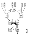
- FIG. 1 is a block diagram illustrating a VPLS-EAPS configuration according to various embodiments.
- a VPLS-EAPS configuration involves multiple attachment points between a VPLS network and an EAPS network, the attachments normally active.
- VPLS core nodes 110, 112, 114 and 116 are linked via pseudowires.
- a link refers to any line or channel over which data is transmitted.
- a pseudowire refers to a mechanism for emulating various networking or telecommunications services across packet-switched networks, such as those mechanisms that use Ethernet, Internet Protocol (IP), Label Switched Paths (LSPs), Multi-protocol Label Switching (MPLS) and/or the like.
- IP Internet Protocol
- LSPs Label Switched Paths
- MPLS Multi-protocol Label Switching
- Emulated services can include T1 leased line, frame relay, Ethernet, Asynchronous Transfer Mode (ATM), time-division multiplexing (TDM), or Synchronous Optical Networking (SONET)/Synchronous Digital Hierarchy (SDH).
- ATM Asynchronous Transfer Mode
- TDM time-division multiplexing
- SONET Synchronous Optical Networking
- SDH Synchronous Digital Hierarchy
- VPLS core nodes 110 and 112 are attached to the EAPS access ring. Rather than having core node 110 or 112 function as the EAPS master node, distribution node 124 is designated as the master node.
- the master node in an EAPS system receives control messages over the control VLAN, the control messages indicating the network failure.
- the master node blocks the protected data VLAN traffic from traversing its secondary port.
- the master node unblocks its secondary port and routes the protected data VLAN traffic through its secondary port. The secondary port is re-blocked once the failure has been fixed.
- any node in the EAPS ring that is not a VPLS node can be designated as the EAPS master node.
- the VPLS core nodes attached to the EAPS ring function as EAPS controller and partner nodes, respectively.
- core node 110 functions as the controller node while core node 112 functions as the partner node.
- the EAPS controller node e.g., core node 110
- a VPLS customer VLAN or VMAN
- VLAN virtualized local area network
- shared-link refers to a special EAPS link that is typically shared among multiple EAPS rings. While a shared-link is often shared among multiple EAPS rings, a shared-link can also be maintained for a single EAPS ring.
- functions and/or mechanisms associated with the shared-link e.g., controller node state machine, etc. may be used to assist in managing communication between EAPS and VPLS.
- the EAPS master node (e.g., node 124) does not necessarily have or receive any information regarding the connection change between core nodes 110 and 112. However, the EAPS functionality on core nodes 110 and 112 do have information regarding the connection change given that the connection change requires configuring an EAPS-protected VLAN with only one port on the ring. It should be noted that this configuration does not change the EAPS control VLAN - the EAPS ring is still complete and the EAPS master node (e.g., node 124) still blocks a port on the customer access VLAN when the ring is intact.
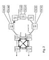
- Figure 2 shows an example of a link failure, in this case between nodes 122 and 124.
- various embodiments of the VPLS-EAPS configuration appropriately handle access ring failures like the link failure shown in Fig. 2 .
- the EAPS master node e.g., node 12
- detects a topology change e.g., due to a link failure notification from a node on the ring, a hello timeout, etc.
- the master node unblocks its secondary port on the protected VLAN.
- the only difference in Fig. 2 (as compared to Fig. 1 ) is that the link failure and subsequent unblocking of the master node's secondary port causes node 124 to now connect to the VPLS network via core node 112 instead of via core node 110.
- connectivity is recovered.
- the connectivity recovery scenario changes when the shared-link between core nodes 110 and 112 fails.
- the EAPS master node e.g., node 12
- the EAPS master node again unblocks its secondary port (as it does whenever there is a failure on the access ring).
- both VPLS core nodes i.e., nodes 110 and 112 might receive a copy of any traffic that is not destined for a node on the EAPS access ring.
- core nodes 110 and 112 might each receive a copy of the packet.
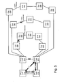
- VPLS core node 110 (functioning as the EAPS controller node) takes the action of removing and/or disabling all pseudowires associated with core node 110 when the shared-link between core nodes 110 and 112 fails. The removal of pseudowires can be seen in Fig. 3 .
- core node 110 When core node 110 removes its pseudowires, core node 110 also signals its VPLS peers (e.g., VPLS core nodes 114, 116, and 112) to inform them that the pseudowires are no longer active. In some embodiments, this signaling is accomplished by completely withdrawing the pseudowires. In other embodiments, the signaling is accomplished by indicating a "standby" state for the pseudowires.
- VPLS peers e.g., VPLS core nodes 114, 116, and 112
- Figure 4 shows a link failure on both the shared-link (i.e., the link between nodes 110 and 112) and on the access ring (e.g., between nodes 122 and 124).
- VPLS core nodes 110 and 112 do not both receive a copy of ring traffic, unlike the scenario where only the shared-link fails.
- the only path to the VPLS network for distribution node 122 is through core node 110 in this dual failure scenario.
- the only path to the VPLS network for distribution node 128 is through core node 112.
- core node 110 maintains its pseudowires rather than removing and/or disabling the pseudowires.
- FIG. 5 illustrates multiple parallel EAPS access rings attached to a VPLS core network.
- each of the EAPS rings is attached to both core node 210 and core node 212.
- Each of the EAPS rings shares the link (i.e., the shared-link) between node 210 and node 212.
- Functions and/or mechanisms associated with the shared-link manage and/or maintain EAPS topology information that can be propagated to the VPLS network.
- any of the parallel EAPS rings is complete, there exists a path to both core VPLS nodes - in this case, nodes 210 and 212.
- the controller node e.g., core node 210 must disable all pseudowires associated with the controller node if and when any of the parallel EAPS rings are complete or "up" (e.g., no link failures) and the shared-link is failed.
- changes in topology on either the access ring(s) or the VPLS network may cause changes to the path(s) used to reach customer devices.
- the path that distribution node 124 would take to reach other parts of the VPLS network changes following the failure on the access ring of the link between nodes 122 and 124.
- node 124 Prior to failure of that link, node 124 reached the VPLS network via core node 110.
- node 124 accesses the VPLS network via core node 112.
- the EAPS master node e.g., node 124 in Fig. 1 , node 222 in Fig. 5 , etc.
- the flush message causes the ring's MAC addresses to be relearned on each node in the ring.
- the flush message is an EAPS message that is propagated to the other nodes on the ring, the flush message is not inherently propagated over the VPLS network.
- the attachments at the remote VPLS nodes may not be utilizing EAPS.
- VPLS node 114 ( Fig .
- EAPS informs VPLS about any received EAPS "flush FDB" messages on both the controller and partner nodes (e.g., nodes 110 and 112).
- the controller and partner nodes can then propagate this information so that other VPLS nodes can flush their respective forwarding databases (e.g., MAC addresses, etc.).
- MAC addresses for example, are learned from a particular originating node (e.g., VPLS node 116 learns the MAC address for node 128 from VPLS node 112)
- both the controller and the partner node inform the other VPLS nodes of any topology changes.
- FIG. 6 is a flow diagram illustrating a process for redundant connectivity between a VPLS network and an EAPS network.
- Two VPLS nodes are provided 310 to function as an EAPS controller node and partner node, respectively.
- the two VPLS nodes are linked by a pseudowire across an EAPS shared-link.
- Additional EAPS nodes are also provided 320.
- the additional EAPS nodes are linked to each other and one of the additional EAPS nodes is designated as a master node.
- Links are also established between the VPLS nodes and the EAPS nodes such that one or more EAPS rings are formed 330.
- Each EAPS ring includes the shared-link between the first and second VPLS nodes.
- the EAPS rings are monitored 340 to detect link failures.
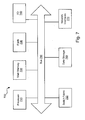
- Figure 7 is a block diagram illustrating a suitable computing environment for practicing various embodiments described herein. Collectively, these components are intended to represent a broad category of hardware systems, including but not limited to general purpose computer systems and specialized network switches.
- Computer system 700 includes processor 710, I/O devices 740, main memory 720 and flash memory 730 coupled to each other via a bus 780.
- Main memory 720 which can include one or more of system memory (RAM), and nonvolatile storage devices (e.g., magnetic or optical disks), stores instructions and data for use by processor 710.
- the network interfaces 770, data storage 760, and switch fabric 750 are coupled to each other via a bus 780.
- Data storage 760 represents the routing database (e.g., forwarding database tables, etc.) described herein as well as other storage areas such as packet buffers, etc., used by the switch fabric 750 for forwarding network packets or messages.
- computer system 700 may be rearranged in various embodiments, and some embodiments may not require nor include all of the above components.
- additional components may be included in system 700, such as additional processors (e.g., a digital signal processor), storage devices, memories, network/communication interfaces, etc.
- methods and apparatuses for providing redundant connectivity between an EAPS network and a VPLS network may be implemented as a series of software routines run by computer system 700 of Fig. 7 .
- These software routines comprise a plurality or series of instructions to be executed by a processing system in a hardware system, such as processor 710.
- the series of instructions are stored on a data storage device 760 (e.g., in a route manager database), memory 720 or flash 730.
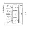
- Routing device 810 includes a VPLS control component 812, a pseudowire (PW) control component 814, an EAPS control component 816, and a Bridge control component 818.
- the VPLS control component 812 facilitates establishing a complete VPLS comprised of multiple PWs.
- the PW control function 814 establishes the individual PWs and signals PW state information to peers.
- the EAPS control function 816 monitors and controls EAPS operation.
- the bridge control function 818 monitors and controls normal L2 bridge operation.
- the EAPS control function 816 provides the VPLS control 812 and/or PW control 814 functions with information about the state of the EAPS shared-link and the EAPS ring connectivity.
- the VPLS forwarding logic component 820, the PW forwarding logic component 822, and the bridge forwarding component 824 combine to forward data packets between PWs and VPLS customers. These forwarding components are coupled via bus 826. Based on the logic of these components, traffic is routed on the routing device ports 828.
- Routing device 810 is an example of a routing device that could be used for VPLS core nodes 110 and/or 112 of Fig. 2 , for example.
- Various components described herein may be a means for performing the functions described herein.
- Each component described herein includes software, hardware, or a combination of these.
- the components can be implemented as software modules, hardware modules, special-purpose hardware (e.g., application specific hardware, application specific integrated circuits (ASICs), digital signal processors (DSPs), etc.), embedded controllers, hardwired circuitry, etc.
- Software content e.g., data, instructions, configuration
- ASICs application specific integrated circuits
- DSPs digital signal processors
- Software content e.g., data, instructions, configuration
- the content may result in a computer performing various functions/operations described herein.
- a computer readable medium includes any mechanism that provides (i.e., stores and/or transmits) information in a form accessible by a computing device (e.g., computer, PDA, electronic system, etc.), such as recordable/non-recordable media (e.g., read only memory (ROM), random access memory (RAM), magnetic disk storage media, optical storage media, flash memory devices, etc.).
- the content may be directly executable ("object” or “executable” form), source code, or the like.
- a computer readable medium may also include a storage or database from which content can be downloaded.
- a computer readable medium may also include a device or product having content stored thereon at a time of sale or delivery. Thus, delivering a device with stored content, or offering content for download over a communication medium may be understood as providing an article of manufacture with such content described herein.
Landscapes
- Engineering & Computer Science (AREA)
- Computer Networks & Wireless Communication (AREA)
- Signal Processing (AREA)
- Computer Security & Cryptography (AREA)
- Environmental & Geological Engineering (AREA)
- Data Exchanges In Wide-Area Networks (AREA)
- Small-Scale Networks (AREA)
Description
- Embodiments of the invention relate to computer networking, and more particularly to redundantly connecting a VPLS network with an EAPS network.
- Computer networks are becoming increasingly important for businesses and communities. Cost efficiency, network capacity, scalability and flexibility are all important considerations in building and maintaining various networks. With a wide variety of services, protocols and technologies, it can be difficult to integrate and/or provide connectivity between different types of networks.
- Virtual Private LAN Service (VPLS) is a way to provide Ethernet based multipoint to multipoint communication over IP/MPLS networks. VPLS allows geographically dispersed sites to share an Ethernet broadcast domain by connecting sites through pseudowires (PWs).
- Ethernet Automatic Protection Switching (EAPS), offered by Extreme Networks of Santa Clara, CA, is a solution for fault-tolerant networks. EAPS provides for a loop-free operation and a sub-second ring recovery. EAPS version 2 (EAPSv2) is configured and enabled to avoid the potential of super loops in environments where multiple EAPS domains share a common link. EAPSv2 functions use the concept of a "controller" and a "partner" mechanism. Shared port status is verified using health protocol data units (PDUs) exchanged by controller and partner. When a shared-link goes down, the configured controller will open only one segment port for each of the protected VLANs, keeping all other segment ports in a blocking state.
- The Internet Engineering Task Force (IETF) RFC 4762, entitled "Virtual Private LAN Service (VPLS) Using Label Distribution Protocol (LDP) Signaling" proposes the use of redundant pseudowires (PWs) to attach to a VPLS core network. However, this technique is applicable only where a single attachment node is necessary. The IETF draft entitled "VPLS Interoperability with CE Bridges" also discusses redundant access to VPLS core networks. However, this technique does not address ring-based access networks and it utilizes only a single active attachment to a VPLS network. Likewise, the IETF draft entitled "Pseudowire (PW) Redundancy" discusses redundant access to VPLS core networks, but fails to address ring-based access networks and only utilizes a single active attachment to a VPLS core network.
- The internet Engineering Task Force (IETF) Standard-Working-Draft entitled "VPLS Interoperability with CE Bridges; draft-sajassi-12vpn-vpls-bridge-interop-02.txt" by Sajassi et al., illustrates a clear demarcation between the IEEE bridge module and IETF LAN emulation module. By doing so, it shows that the majority of interoperability issues with CE bridges can be delegated to the 802.1ad bridge module, thus removing the burden on the IETF LAN emulation module within a VPLS PE.
- This invention is described by the
independent claims 1, 10 and 11. Embodiments disclosed herein provide redundant connectivity between an Ethernet Automatic Protection Switching (EAPS) access network and a Virtual Private LAN Service (VPLS) network. A first VPLS node is provided to function as an EAPS controller node. A second VPLS node is provided to function as an EAPS partner node. The first and second VPLS nodes are linked by a pseudowire. This pseudowire is normally transmitted across an EAPS shared-link. Additional EAPS nodes are also provided. The additional EAPS nodes are linked to each other and one of the additional EAPS nodes is designated as a master node. Links are also established between the VPLS nodes and the EAPS nodes such that one or more EAPS rings are formed. Each EAPS ring includes the shared-link between the first and second VPLS nodes. The EAPS rings are monitored to detect link failures. When a failure of the shared-link between the first and second VPLS nodes is detected, all pseudowire links associated with the first VPLS node are disabled if any of the EAPS nodes has a path to both of the VPLS nodes. Otherwise, the existing pseudowire links associated with the first VPLS node are maintained. - The following description includes discussion of figures having illustrations given by way of example of implementations of embodiments of the invention. The drawings should be understood by way of example, and not by way of limitation. As used herein, references to one or more "embodiments" are to be understood as describing a particular feature, structure, or characteristic included in at least one implementation of the invention. Thus, phrases such as "in one embodiment" or "in an alternate embodiment" appearing herein describe various embodiments and implementations of the invention, and do not necessarily all refer to the same embodiment. However, they are also not necessarily mutually exclusive.
-
Figure 1 is a block diagram illustrating a VPLS-EAPS configuration according to various embodiments. -
Figure 2 is a block diagram illustrating a VPLS-EAPS configuration according to various embodiments. -
Figure 3 is a block diagram illustrating a VPLS-EAPS configuration according to various embodiments. -
Figure 4 is a block diagram illustrating a VPLS-EAPS configuration according to various embodiments. -
Figure 5 is a block diagram illustrating a VPLS-EAPS configuration according to various embodiments. -
Figure 6 is a flow diagram illustrating a process for redundant connectivity between a VPLS network and an EAPS network according to various embodiments. -
Figure 7 is a block diagram illustrating a suitable computing environment for practicing various embodiments described herein. -
Figure 8 is a block diagram illustrating a routing device according to various embodiments. - As provided herein, methods, apparatuses, and systems enable redundant connectivity between a Virtual Private LAN Service (VPLS) network and an Ethernet Automatic Protection Switching (EAPS) network. More particularly, multiple active attachments to a VPLS network are provided in various embodiments.
-
Figure 1 is a block diagram illustrating a VPLS-EAPS configuration according to various embodiments. As used herein, a VPLS-EAPS configuration involves multiple attachment points between a VPLS network and an EAPS network, the attachments normally active. As shown,VPLS core nodes - As shown in
Fig. 1 ,VPLS core nodes core node distribution node 124 is designated as the master node. When a network failure is detected on the ring, the master node in an EAPS system receives control messages over the control VLAN, the control messages indicating the network failure. During normal operation, the master node blocks the protected data VLAN traffic from traversing its secondary port. During a network failure, the master node unblocks its secondary port and routes the protected data VLAN traffic through its secondary port. The secondary port is re-blocked once the failure has been fixed. In various embodiments, any node in the EAPS ring that is not a VPLS node can be designated as the EAPS master node. In various embodiments, the VPLS core nodes attached to the EAPS ring function as EAPS controller and partner nodes, respectively. InFig. 1 ,core node 110 functions as the controller node whilecore node 112 functions as the partner node. The EAPS controller node (e.g., core node 110) includes a controller state machine, which keeps track of whether EAPS nodes on the ring have access to both attached VPLS nodes (e.g.,core nodes 110 and 112). - In various embodiments, when a VPLS customer VLAN (or VMAN) is attached to an EAPS ring, as shown in
Fig. 1 , the EAPS ring segment betweencore nodes core nodes core nodes core nodes -
Figure 2 shows an example of a link failure, in this case betweennodes Fig. 2 . When the EAPS master node (e.g., node 124) detects a topology change (e.g., due to a link failure notification from a node on the ring, a hello timeout, etc.), the master node unblocks its secondary port on the protected VLAN. The only difference inFig. 2 (as compared toFig. 1 ) is that the link failure and subsequent unblocking of the master node's secondary port causesnode 124 to now connect to the VPLS network viacore node 112 instead of viacore node 110. Thus, connectivity is recovered. - The connectivity recovery scenario changes when the shared-link between
core nodes Figure 3 , when the shared-link fails, the EAPS master node (e.g., node 124) again unblocks its secondary port (as it does whenever there is a failure on the access ring). However, when this occurs, both VPLS core nodes (i.e.,nodes 110 and 112) might receive a copy of any traffic that is not destined for a node on the EAPS access ring. For example, if the shared-link betweencore nodes distribution node 126 was trying to send a packet toVPLS core node 116,core nodes core nodes node 112 tonode 116 tonode 114 to node 110), this scenario could result in a traffic loop on the EAPS access ring as well as a storm into the VPLS network. To prevent this scenario from occurring, VPLS core node 110 (functioning as the EAPS controller node) takes the action of removing and/or disabling all pseudowires associated withcore node 110 when the shared-link betweencore nodes Fig. 3 . Once the pseudowires have been removed and/or disabled, all traffic traveling between the EAPS access network and the VPLS network passes throughVPLS core node 112. When core node 110 (i.e., the controller node) detects that the shared-link betweennodes - When
core node 110 removes its pseudowires,core node 110 also signals its VPLS peers (e.g.,VPLS core nodes -
Figure 4 shows a link failure on both the shared-link (i.e., the link betweennodes 110 and 112) and on the access ring (e.g., betweennodes 122 and 124). In a dual failure scenario such as this,VPLS core nodes Fig. 4 , the only path to the VPLS network fordistribution node 122 is throughcore node 110 in this dual failure scenario. Similarly, the only path to the VPLS network fordistribution node 128 is throughcore node 112. Accordingly, in a dual failure scenario where one of the failed links is the VPLS core shared-link,core node 110 maintains its pseudowires rather than removing and/or disabling the pseudowires. -
Figure 5 illustrates multiple parallel EAPS access rings attached to a VPLS core network. As shown, each of the EAPS rings is attached to bothcore node 210 andcore node 212. Each of the EAPS rings shares the link (i.e., the shared-link) betweennode 210 andnode 212. Functions and/or mechanisms associated with the shared-link manage and/or maintain EAPS topology information that can be propagated to the VPLS network. Here, as long as any of the parallel EAPS rings is complete, there exists a path to both core VPLS nodes - in this case,nodes nodes Fig. 5 , this causes no problems because each of these rings has an additional link failure on the ring which prevents nodes in these rings from having a path to both VPLS core nodes (i.e.,nodes 210 and 212). However, the outer ring has no other link failures. Thus, distribution nodes (e.g., 250, 252, 254 and 256) on this outer ring do have a path to bothVPLS nodes Table 1 Core Link State Ring State Core Link Up Core Link Down Any Parallel Ring Up PWs Active PWs Inactive Any Parallel Ring Down PWs Active PWs Active - In various embodiments, changes in topology on either the access ring(s) or the VPLS network may cause changes to the path(s) used to reach customer devices. For example, in
Fig. 2 , the path thatdistribution node 124 would take to reach other parts of the VPLS network changes following the failure on the access ring of the link betweennodes node 124 reached the VPLS network viacore node 110. Following the failure,node 124 accesses the VPLS network viacore node 112. - When the EAPS master node (e.g.,
node 124 inFig. 1 ,node 222 inFig. 5 , etc.) detects a topology change, it sends a "flush FDB" message to its other transit nodes (i.e., the other nodes on the ring). In some embodiments, the flush message causes the ring's MAC addresses to be relearned on each node in the ring. Given that the flush message is an EAPS message that is propagated to the other nodes on the ring, the flush message is not inherently propagated over the VPLS network. Also, the attachments at the remote VPLS nodes may not be utilizing EAPS. Using the above example, VPLS node 114 (Fig. 2 ) would expect to findnode 124 via the pseudowire betweenVPLS node 114 andVPLS node 110. However, upon the occurrence of a link failure betweennodes VPLS node 114 tonode 124 viaVPLS node 110 will not reach its destination given thatVPLS node 114 is not aware of the topology change and is configured to send traffic on a path through the failed link. To overcome this problem, EAPS informs VPLS about any received EAPS "flush FDB" messages on both the controller and partner nodes (e.g.,nodes 110 and 112). The controller and partner nodes can then propagate this information so that other VPLS nodes can flush their respective forwarding databases (e.g., MAC addresses, etc.). Given that MAC addresses, for example, are learned from a particular originating node (e.g.,VPLS node 116 learns the MAC address fornode 128 from VPLS node 112), both the controller and the partner node inform the other VPLS nodes of any topology changes. -
Figure 6 is a flow diagram illustrating a process for redundant connectivity between a VPLS network and an EAPS network. Two VPLS nodes are provided 310 to function as an EAPS controller node and partner node, respectively. The two VPLS nodes are linked by a pseudowire across an EAPS shared-link. Additional EAPS nodes are also provided 320. The additional EAPS nodes are linked to each other and one of the additional EAPS nodes is designated as a master node. Links are also established between the VPLS nodes and the EAPS nodes such that one or more EAPS rings are formed 330. Each EAPS ring includes the shared-link between the first and second VPLS nodes. The EAPS rings are monitored 340 to detect link failures. When a failure of the pseudowire shared-link between the first and second VPLS nodes is detected 350, it is determined 360 whether any of the EAPS nodes has a path to both of the VPLS nodes. If yes, then all pseudowires associated with the controller node are disabled 370. If no, then the existing pseudowire links associated with the first VPLS node are maintained 380. -
Figure 7 is a block diagram illustrating a suitable computing environment for practicing various embodiments described herein. Collectively, these components are intended to represent a broad category of hardware systems, including but not limited to general purpose computer systems and specialized network switches. -
Computer system 700 includesprocessor 710, I/O devices 740,main memory 720 andflash memory 730 coupled to each other via a bus 780.Main memory 720, which can include one or more of system memory (RAM), and nonvolatile storage devices (e.g., magnetic or optical disks), stores instructions and data for use byprocessor 710. Additionally, the network interfaces 770,data storage 760, and switchfabric 750 are coupled to each other via a bus 780.Data storage 760 represents the routing database (e.g., forwarding database tables, etc.) described herein as well as other storage areas such as packet buffers, etc., used by theswitch fabric 750 for forwarding network packets or messages. - The various components of
computer system 700 may be rearranged in various embodiments, and some embodiments may not require nor include all of the above components. Furthermore, additional components may be included insystem 700, such as additional processors (e.g., a digital signal processor), storage devices, memories, network/communication interfaces, etc. - In the illustrated embodiment of
Fig. 7 , methods and apparatuses for providing redundant connectivity between an EAPS network and a VPLS network according to the present invention as discussed above may be implemented as a series of software routines run bycomputer system 700 ofFig. 7 . These software routines comprise a plurality or series of instructions to be executed by a processing system in a hardware system, such asprocessor 710. Initially, the series of instructions are stored on a data storage device 760 (e.g., in a route manager database),memory 720 orflash 730. -
Figure 8 illustrates the various components of a routing device that may be used in various embodiments.Routing device 810 includes aVPLS control component 812, a pseudowire (PW)control component 814, anEAPS control component 816, and aBridge control component 818. TheVPLS control component 812 facilitates establishing a complete VPLS comprised of multiple PWs. ThePW control function 814 establishes the individual PWs and signals PW state information to peers. TheEAPS control function 816 monitors and controls EAPS operation. Thebridge control function 818 monitors and controls normal L2 bridge operation. TheEAPS control function 816 provides theVPLS control 812 and/orPW control 814 functions with information about the state of the EAPS shared-link and the EAPS ring connectivity. The VPLSforwarding logic component 820, the PWforwarding logic component 822, and thebridge forwarding component 824 combine to forward data packets between PWs and VPLS customers. These forwarding components are coupled via bus 826. Based on the logic of these components, traffic is routed on therouting device ports 828.Routing device 810 is an example of a routing device that could be used forVPLS core nodes 110 and/or 112 ofFig. 2 , for example. - Various components described herein may be a means for performing the functions described herein. Each component described herein includes software, hardware, or a combination of these. The components can be implemented as software modules, hardware modules, special-purpose hardware (e.g., application specific hardware, application specific integrated circuits (ASICs), digital signal processors (DSPs), etc.), embedded controllers, hardwired circuitry, etc. Software content (e.g., data, instructions, configuration) may be provided via an article of manufacture including a computer readable medium, which provides content that represents instructions that can be executed. The content may result in a computer performing various functions/operations described herein. A computer readable medium includes any mechanism that provides (i.e., stores and/or transmits) information in a form accessible by a computing device (e.g., computer, PDA, electronic system, etc.), such as recordable/non-recordable media (e.g., read only memory (ROM), random access memory (RAM), magnetic disk storage media, optical storage media, flash memory devices, etc.). The content may be directly executable ("object" or "executable" form), source code, or the like. A computer readable medium may also include a storage or database from which content can be downloaded. A computer readable medium may also include a device or product having content stored thereon at a time of sale or delivery. Thus, delivering a device with stored content, or offering content for download over a communication medium may be understood as providing an article of manufacture with such content described herein.
- Besides what is described herein, various modifications may be made to the disclosed embodiments and implementations of the invention without departing from their scope. Therefore, the illustrations and examples herein should be construed in an illustrative, and not a restrictive sense. The scope of the invention should be measured solely by reference to the claims that follow.
Claims (15)
- A method for providing redundant access to a Virtual Private LAN Service VPLS network characterized by a method for providing redundant connectivity between an Ethernet Automatic Protection Switching EAPS access network and the VPLS network, the latter method comprising:providing (310) a first VPLS node of a plurality of VPLS nodes (110, 112, 114, 116), to function as an EAPS controller node;providing (310) a second VPLS node (112) of a plurality of VPLS0 nodes (110, 112, 114, 116), wherein the plurality of VPLS nodes (110, 112, 114, 116) including the first and second VLPS nodes (110, 112) are linked with each other by pseudowire links PWs, and wherein the first and second VPLS nodes (110, 112) are linked with each other by an EAPS shared-link;establishing (330) an EAPS ring coupling the first VPLS node (110), the second VPLS node (112), and a plurality of EAPS nodes (122, 124, 126, 128, 130);detecting a network failure (350) of the EAPS shared-link between the first and second VPLS nodes (110, 114); anddisabling (370, 360), in response to detecting the failure, all pseudowire links PWs associated with the first VPLS node (110) when any of the plurality of EAPS nodes (122, 124, 126, 128, 130) has a path to both the first and second VPLS nodes (110, 112).
- The method of claim 1 further comprising:maintaining (380, 360), in response to detecting the failure, existing pseudowire links associated with the first VPLS node (110) when any of the plurality of EAPS nodes (122, 124, 126, 128, 130) lacks a path to both the first and second VPLS nodes (110, 112).
- The method of claim 1, wherein the first and second VPLS nodes (110, 112) are normally active, and wherein the first VPLS node (110) comprises a controller state machine to track whether each of the plurality of EAPS nodes (122, 124, 126, 128, 130) has access to the first and the second VPLS nodes (110, 112).
- The method of claim 1 further comprising:monitoring (340) the EAPS ring; andflushing forwarding database addresses on the plurality of VPLS nodes (110, 112, 114, 116) in response to detecting a network failure on the monitored EAPS ring.
- The method of claim 1, wherein disabling all pseudowire links associated with the first VPLS node (110) further comprises communicating an indication of the disabled pseudowire links to VPLS nodes of the plurality of VPLS nodes (110, 112, 114, 116) coupled by the pseudowire links with the first VPLS node (110).
- The method of claim 1, wherein the pseudowire link between the first and second VPLS nodes (110, 112) replaces part of a customer virtual local area network VLAN.
- The method of claim 1, wherein one of the pluralities of EAPS nodes (122, 124, 126, 128, 130) is designated as a master node (124), the master node (124) to receive a control message indicating a network failure in the EAPS ring.
- The method of claim 7 further comprises:blocking a secondary port of the master node (124) during normal operation; andunblocking the secondary port of the master node (124) in response to detecting the network failure (350).
- The method of claim 1 further comprising reestablishing pseudowire links between the VPLS nodes (110, 112) when the first VPLS node (110) detects that a shared-link between the VPLS nodes (110, 112) is repaired.
- An article of manufacture comprising a computer-readable medium (760) having content stored thereon to provide instructions, that when executed, causes an electronic device (710) to perform any of one of claims 1 to 9.
- A system for providing redundant access to a Virtual Private LAN Service VPLS network characterized by a system for providing redundant connectivity between an Ethernet Automatic Protection Switching EAPS access network and a VPLS network, the latter system comprising:means for providing (310) a first VPLS node (810, 110) of a plurality of VPLS nodes (110, 112, 114, 116), to function as an EAPS controller node;means for providing (310) a second VPLS node (810, 112) of a plurality of VPLS nodes (110, 112, 114, 116), wherein the plurality of VPLS nodes including the first and second VLPS nodes (110, 112) are linked via ports (828) with each other by pseudowire links PWs and wherein the first and second VPLS nodes (110, 112) are linked via ports (828) with each other by an EAPS shared-link;means for establishing (330) an EAPS ring coupling the first VPLS node (810, 110), the second VPLS node (810, 110), and a plurality of EAPS nodes (122, 124, 126, 128, 130);means for detecting a network failure (350, 816) of the EAPS shared-link between the first and second VPLS nodes (110, 114); andmeans for disabling (370, 360, 822), in response to detecting the failure, all pseudowire links PWs associated with the first VPLS node (110) when any of the plurality of EAPS nodes (122, 124, 126, 128, 130) has a path to both the first and second VPLS nodes (110, 112).
- The system of claim 11 further comprising:means for maintaining (380, 360, 822), in response to detecting the failure, existing pseudowire links associated with the first VPLS node (110) when any of the plurality of EAPS nodes (122, 124, 126, 128, 130) lacks a path to both the first and second VPLS nodes (110, 112).
- The system of claim 11 further comprising means for monitoring (340, 816) the EAPS ring, wherein the first and second routing devices (110, 112) are normally active.
- The system of claim 11, wherein each VPLS node of the plurality of VPLS nodes (110, 112, 114, 116) includes a forwarding logic component (820, 822, 824) to forward data packets to customers of VPLS.
- The system of claim 11, wherein each VPLS node of the plurality of VPLS nodes (110, 112, 114, 116) includes a pseudowire control logic (814) to indicate a state of the pseudowire links to the VPLS nodes of the plurality of VPLS nodes 110, 112, 114, 116), wherein the plurality of VPLS nodes 110, 112, 114, 116) are coupled to the pseudowire links via the ports (828).
Priority Applications (1)
| Application Number | Priority Date | Filing Date | Title |
|---|---|---|---|
| EP12173669.8A EP2518954B1 (en) | 2008-04-11 | 2009-03-09 | Redundant ethernet automatic protection switching access to virtual private lan services. |
Applications Claiming Priority (2)
| Application Number | Priority Date | Filing Date | Title |
|---|---|---|---|
| US12/101,603 US7990850B2 (en) | 2008-04-11 | 2008-04-11 | Redundant Ethernet automatic protection switching access to virtual private LAN services |
| PCT/US2009/036548 WO2009126390A1 (en) | 2008-04-11 | 2009-03-09 | Redundant ethernet automatic protection switching access to virtual private lan services |
Related Child Applications (2)
| Application Number | Title | Priority Date | Filing Date |
|---|---|---|---|
| EP12173669.8A Division EP2518954B1 (en) | 2008-04-11 | 2009-03-09 | Redundant ethernet automatic protection switching access to virtual private lan services. |
| EP12173669.8A Division-Into EP2518954B1 (en) | 2008-04-11 | 2009-03-09 | Redundant ethernet automatic protection switching access to virtual private lan services. |
Publications (3)
| Publication Number | Publication Date |
|---|---|
| EP2277290A1 EP2277290A1 (en) | 2011-01-26 |
| EP2277290B1 true EP2277290B1 (en) | 2014-08-13 |
| EP2277290B9 EP2277290B9 (en) | 2014-11-19 |
Family
ID=40589747
Family Applications (2)
| Application Number | Title | Priority Date | Filing Date |
|---|---|---|---|
| EP09730176.6A Active EP2277290B9 (en) | 2008-04-11 | 2009-03-09 | Redundant ethernet automatic protection switching access to virtual private LAN services |
| EP12173669.8A Active EP2518954B1 (en) | 2008-04-11 | 2009-03-09 | Redundant ethernet automatic protection switching access to virtual private lan services. |
Family Applications After (1)
| Application Number | Title | Priority Date | Filing Date |
|---|---|---|---|
| EP12173669.8A Active EP2518954B1 (en) | 2008-04-11 | 2009-03-09 | Redundant ethernet automatic protection switching access to virtual private lan services. |
Country Status (5)
| Country | Link |
|---|---|
| US (4) | US7990850B2 (en) |
| EP (2) | EP2277290B9 (en) |
| JP (1) | JP5548673B2 (en) |
| CN (1) | CN101999224B (en) |
| WO (1) | WO2009126390A1 (en) |
Families Citing this family (38)
| Publication number | Priority date | Publication date | Assignee | Title |
|---|---|---|---|---|
| CN101534233A (en) * | 2008-03-12 | 2009-09-16 | 中兴通讯股份有限公司 | Method for updating Ethernet ring network node address table |
| US7990850B2 (en) | 2008-04-11 | 2011-08-02 | Extreme Networks, Inc. | Redundant Ethernet automatic protection switching access to virtual private LAN services |
| US20100226245A1 (en) * | 2009-02-16 | 2010-09-09 | Jeong-Dong Ryoo | Method and apparatus for protection switching in ring network |
| JP5168230B2 (en) * | 2009-05-26 | 2013-03-21 | 富士通株式会社 | Communication system, edge router, and signal transfer method |
| CN101789903B (en) * | 2009-12-30 | 2012-05-23 | 华为技术有限公司 | Method, device and system for protecting semi-ring network |
| EP2553882B1 (en) | 2010-03-30 | 2014-07-16 | Telefonaktiebolaget LM Ericsson (publ) | Method for protecting an ethernet ring from a superloop going through the ethernet ring |
| EP2553881B1 (en) * | 2010-03-30 | 2015-01-21 | Telefonaktiebolaget LM Ericsson (publ) | Method for protection against superloops in an ethernet ring |
| CN102377626A (en) * | 2010-08-19 | 2012-03-14 | 盛科网络(苏州)有限公司 | Dual-homing-supporting ring networking method based on virtual private local area network service (VPLS) and Ethernet automatic protection switching (EAPS) |
| US9813257B2 (en) * | 2010-09-10 | 2017-11-07 | Extreme Networks, Inc. | Access network dual path connectivity |
| US9164806B2 (en) | 2011-01-28 | 2015-10-20 | Oracle International Corporation | Processing pattern framework for dispatching and executing tasks in a distributed computing grid |
| US9201685B2 (en) | 2011-01-28 | 2015-12-01 | Oracle International Corporation | Transactional cache versioning and storage in a distributed data grid |
| US9063787B2 (en) | 2011-01-28 | 2015-06-23 | Oracle International Corporation | System and method for using cluster level quorum to prevent split brain scenario in a data grid cluster |
| US9063852B2 (en) * | 2011-01-28 | 2015-06-23 | Oracle International Corporation | System and method for use with a data grid cluster to support death detection |
| US9081839B2 (en) | 2011-01-28 | 2015-07-14 | Oracle International Corporation | Push replication for use with a distributed data grid |
| CN103023771A (en) * | 2011-09-28 | 2013-04-03 | 华为技术有限公司 | Method and device for processing fault of ring topological network and routing equipment |
| CN102510354A (en) * | 2011-12-15 | 2012-06-20 | 盛科网络(苏州)有限公司 | Dual-home-supported ring network method and system based on virtual private local area network (LAN) service (VPLS) and G8032 |
| US10706021B2 (en) | 2012-01-17 | 2020-07-07 | Oracle International Corporation | System and method for supporting persistence partition discovery in a distributed data grid |
| CN102857379B (en) * | 2012-09-18 | 2016-08-03 | 中兴通讯股份有限公司 | The protection control method of ethernet ring network inter-node connectivity, device and primary nodal point |
| GB2508355B (en) * | 2012-11-28 | 2021-02-17 | Nomad Digital Ltd | Communication method |
| CN103200172B (en) | 2013-02-19 | 2018-06-26 | 中兴通讯股份有限公司 | A kind of method and system of 802.1X accesses session keepalive |
| WO2014146271A1 (en) * | 2013-03-21 | 2014-09-25 | 华为技术有限公司 | Transmission apparatus, connecting mechanism and method |
| US9319240B2 (en) * | 2013-09-24 | 2016-04-19 | Ciena Corporation | Ethernet Ring Protection node |
| US9225629B2 (en) * | 2014-05-30 | 2015-12-29 | Telefonaktiebolaget L M Ericsson (Publ) | Efficient identification of node protection remote LFA target |
| US10664495B2 (en) | 2014-09-25 | 2020-05-26 | Oracle International Corporation | System and method for supporting data grid snapshot and federation |
| CN105991188B (en) | 2015-02-16 | 2019-09-10 | 阿里巴巴集团控股有限公司 | A kind of method and device detecting sharing memory |
| US10798146B2 (en) | 2015-07-01 | 2020-10-06 | Oracle International Corporation | System and method for universal timeout in a distributed computing environment |
| US11163498B2 (en) | 2015-07-01 | 2021-11-02 | Oracle International Corporation | System and method for rare copy-on-write in a distributed computing environment |
| US10585599B2 (en) | 2015-07-01 | 2020-03-10 | Oracle International Corporation | System and method for distributed persistent store archival and retrieval in a distributed computing environment |
| US10860378B2 (en) | 2015-07-01 | 2020-12-08 | Oracle International Corporation | System and method for association aware executor service in a distributed computing environment |
| AT517779B1 (en) * | 2015-10-01 | 2021-10-15 | B & R Ind Automation Gmbh | Method for cross-traffic between two slaves in a ring-shaped data network |
| JP2017079399A (en) * | 2015-10-20 | 2017-04-27 | 富士通株式会社 | Transmission device and transmission system |
| US11550820B2 (en) | 2017-04-28 | 2023-01-10 | Oracle International Corporation | System and method for partition-scoped snapshot creation in a distributed data computing environment |
| US10769019B2 (en) | 2017-07-19 | 2020-09-08 | Oracle International Corporation | System and method for data recovery in a distributed data computing environment implementing active persistence |
| US20190044848A1 (en) * | 2017-08-01 | 2019-02-07 | Hewlett Packard Enterprise Development Lp | Virtual switching framework |
| US10721095B2 (en) | 2017-09-26 | 2020-07-21 | Oracle International Corporation | Virtual interface system and method for multi-tenant cloud networking |
| US10862965B2 (en) | 2017-10-01 | 2020-12-08 | Oracle International Corporation | System and method for topics implementation in a distributed data computing environment |
| JP7183853B2 (en) * | 2019-02-15 | 2022-12-06 | 日本電信電話株式会社 | NETWORK DEVICE, NETWORK SYSTEM, NETWORK CONNECTION METHOD, AND PROGRAM |
| CN110519148B (en) * | 2019-07-25 | 2022-01-18 | 深圳震有科技股份有限公司 | Method, system and storage medium for establishing VPN channel by multilink backup |
Family Cites Families (16)
| Publication number | Priority date | Publication date | Assignee | Title |
|---|---|---|---|---|
| US7106729B1 (en) * | 2001-10-29 | 2006-09-12 | Ciena Corporation | Switching control mechanism based upon the logical partitioning of a switch element |
| US6766482B1 (en) | 2001-10-31 | 2004-07-20 | Extreme Networks | Ethernet automatic protection switching |
| US7269135B2 (en) | 2002-04-04 | 2007-09-11 | Extreme Networks, Inc. | Methods and systems for providing redundant connectivity across a network using a tunneling protocol |
| JP4020753B2 (en) | 2002-10-25 | 2007-12-12 | 富士通株式会社 | Ring switching method |
| US8520507B1 (en) | 2004-03-08 | 2013-08-27 | Extreme Networks, Inc. | Ethernet automatic protection switching |
| JP4627205B2 (en) | 2005-03-28 | 2011-02-09 | 富士通株式会社 | Ring network system and failure recovery method |
| US7983150B2 (en) | 2006-01-18 | 2011-07-19 | Corrigent Systems Ltd. | VPLS failure protection in ring networks |
| IL176330A0 (en) * | 2006-06-15 | 2007-07-04 | Eci Telecom Ltd | Technique of traffic protection loop-free interconnection for ethernet and/or vpls networks |
| US7626930B2 (en) * | 2006-11-13 | 2009-12-01 | Corrigent Systems Ltd. | Hash-based multi-homing |
| EP2098021A1 (en) | 2006-12-29 | 2009-09-09 | Telefonaktiebolaget Lm Ericsson (publ) | Method of providing data |
| CN100558111C (en) | 2007-02-05 | 2009-11-04 | 华为技术有限公司 | Metro Ethernet provides reliability processing method and the system under the multi-service networking |
| EP1968248B1 (en) * | 2007-03-05 | 2010-06-09 | Alcatel Lucent | Packet ring protection |
| US8964571B2 (en) * | 2007-07-06 | 2015-02-24 | Alcatel Lucent | Method and apparatus for simultaneous support of fast restoration and native multicast in IP networks |
| US7969866B2 (en) * | 2008-03-31 | 2011-06-28 | Telefonaktiebolaget L M Ericsson (Publ) | Hierarchical virtual private LAN service hub connectivity failure recovery |
| US7990850B2 (en) | 2008-04-11 | 2011-08-02 | Extreme Networks, Inc. | Redundant Ethernet automatic protection switching access to virtual private LAN services |
| US8416775B2 (en) * | 2010-05-19 | 2013-04-09 | Juniper Networks, Inc. | Systems and methods for equal-cost multi-path virtual private LAN service |
-
2008
- 2008-04-11 US US12/101,603 patent/US7990850B2/en active Active
-
2009
- 2009-03-09 JP JP2011504028A patent/JP5548673B2/en not_active Expired - Fee Related
- 2009-03-09 CN CN200980112834.9A patent/CN101999224B/en active Active
- 2009-03-09 WO PCT/US2009/036548 patent/WO2009126390A1/en active Application Filing
- 2009-03-09 EP EP09730176.6A patent/EP2277290B9/en active Active
- 2009-03-09 EP EP12173669.8A patent/EP2518954B1/en active Active
-
2011
- 2011-06-21 US US13/165,534 patent/US8797849B2/en active Active
-
2014
- 2014-07-02 US US14/322,643 patent/US9407455B2/en active Active
-
2016
- 2016-06-23 US US15/190,922 patent/US10469366B2/en active Active
Also Published As
| Publication number | Publication date |
|---|---|
| US10469366B2 (en) | 2019-11-05 |
| US20160308756A1 (en) | 2016-10-20 |
| WO2009126390A1 (en) | 2009-10-15 |
| CN101999224A (en) | 2011-03-30 |
| US7990850B2 (en) | 2011-08-02 |
| JP2011518506A (en) | 2011-06-23 |
| US20110249552A1 (en) | 2011-10-13 |
| EP2518954A1 (en) | 2012-10-31 |
| JP5548673B2 (en) | 2014-07-16 |
| US20090257348A1 (en) | 2009-10-15 |
| EP2518954B1 (en) | 2018-05-09 |
| CN101999224B (en) | 2014-01-29 |
| EP2277290B9 (en) | 2014-11-19 |
| US9407455B2 (en) | 2016-08-02 |
| US8797849B2 (en) | 2014-08-05 |
| US20140347980A1 (en) | 2014-11-27 |
| EP2277290A1 (en) | 2011-01-26 |
Similar Documents
| Publication | Publication Date | Title |
|---|---|---|
| US10469366B2 (en) | Redundant ethernet automatic protection switching access to virtual private LAN services | |
| US8780699B1 (en) | Handling switchover of multi-homed connections in VPLS networks | |
| JP4899959B2 (en) | VPN equipment | |
| US9800432B2 (en) | Using ethernet ring protection switching with computer networks | |
| US8018841B2 (en) | Interworking an ethernet ring network and an ethernet network with traffic engineered trunks | |
| US8724452B2 (en) | Technique for protecting communication traffic in a connection having redundancy | |
| US20130272114A1 (en) | Pseudo wire switching method and device | |
| EP1958364B1 (en) | Vpls remote failure indication | |
| US20100287405A1 (en) | Method and apparatus for internetworking networks | |
| WO2012028029A1 (en) | Switching method and system | |
| US20120106321A1 (en) | Method and device for conveying traffic in a network | |
| US20100150160A1 (en) | Interworking oam between ethernet and atm/frame relay networks | |
| WO2010031295A1 (en) | Control method for ethernet failure recovery | |
| IL191454A (en) | Vpls remote failure indication |
Legal Events
| Date | Code | Title | Description |
|---|---|---|---|
| PUAI | Public reference made under article 153(3) epc to a published international application that has entered the european phase |
Free format text: ORIGINAL CODE: 0009012 |
|
| 17P | Request for examination filed |
Effective date: 20101102 |
|
| AK | Designated contracting states |
Kind code of ref document: A1 Designated state(s): AT BE BG CH CY CZ DE DK EE ES FI FR GB GR HR HU IE IS IT LI LT LU LV MC MK MT NL NO PL PT RO SE SI SK TR |
|
| AX | Request for extension of the european patent |
Extension state: AL BA RS |
|
| DAX | Request for extension of the european patent (deleted) | ||
| 17Q | First examination report despatched |
Effective date: 20120113 |
|
| REG | Reference to a national code |
Ref country code: DE Ref legal event code: R079 Ref document number: 602009025952 Country of ref document: DE Free format text: PREVIOUS MAIN CLASS: H04L0012560000 Ipc: H04L0012260000 |
|
| GRAP | Despatch of communication of intention to grant a patent |
Free format text: ORIGINAL CODE: EPIDOSNIGR1 |
|
| RIC1 | Information provided on ipc code assigned before grant |
Ipc: H04L 12/703 20130101ALI20140213BHEP Ipc: H04L 12/24 20060101ALI20140213BHEP Ipc: H04L 12/46 20060101ALI20140213BHEP Ipc: H04L 12/701 20130101ALI20140213BHEP Ipc: H04L 12/707 20130101ALI20140213BHEP Ipc: H04L 12/26 20060101AFI20140213BHEP Ipc: H04L 12/42 20060101ALI20140213BHEP |
|
| INTG | Intention to grant announced |
Effective date: 20140224 |
|
| GRAS | Grant fee paid |
Free format text: ORIGINAL CODE: EPIDOSNIGR3 |
|
| GRAA | (expected) grant |
Free format text: ORIGINAL CODE: 0009210 |
|
| AK | Designated contracting states |
Kind code of ref document: B1 Designated state(s): AT BE BG CH CY CZ DE DK EE ES FI FR GB GR HR HU IE IS IT LI LT LU LV MC MK MT NL NO PL PT RO SE SI SK TR |
|
| REG | Reference to a national code |
Ref country code: GB Ref legal event code: FG4D |
|
| REG | Reference to a national code |
Ref country code: CH Ref legal event code: EP Ref country code: AT Ref legal event code: REF Ref document number: 682776 Country of ref document: AT Kind code of ref document: T Effective date: 20140815 |
|
| REG | Reference to a national code |
Ref country code: IE Ref legal event code: FG4D |
|
| REG | Reference to a national code |
Ref country code: DE Ref legal event code: R096 Ref document number: 602009025952 Country of ref document: DE Effective date: 20140925 |
|
| REG | Reference to a national code |
Ref country code: NL Ref legal event code: VDEP Effective date: 20140813 |
|
| REG | Reference to a national code |
Ref country code: AT Ref legal event code: MK05 Ref document number: 682776 Country of ref document: AT Kind code of ref document: T Effective date: 20140813 |
|
| REG | Reference to a national code |
Ref country code: LT Ref legal event code: MG4D |
|
| PG25 | Lapsed in a contracting state [announced via postgrant information from national office to epo] |
Ref country code: LT Free format text: LAPSE BECAUSE OF FAILURE TO SUBMIT A TRANSLATION OF THE DESCRIPTION OR TO PAY THE FEE WITHIN THE PRESCRIBED TIME-LIMIT Effective date: 20140813 Ref country code: ES Free format text: LAPSE BECAUSE OF FAILURE TO SUBMIT A TRANSLATION OF THE DESCRIPTION OR TO PAY THE FEE WITHIN THE PRESCRIBED TIME-LIMIT Effective date: 20140813 Ref country code: PT Free format text: LAPSE BECAUSE OF FAILURE TO SUBMIT A TRANSLATION OF THE DESCRIPTION OR TO PAY THE FEE WITHIN THE PRESCRIBED TIME-LIMIT Effective date: 20141215 Ref country code: SE Free format text: LAPSE BECAUSE OF FAILURE TO SUBMIT A TRANSLATION OF THE DESCRIPTION OR TO PAY THE FEE WITHIN THE PRESCRIBED TIME-LIMIT Effective date: 20140813 Ref country code: GR Free format text: LAPSE BECAUSE OF FAILURE TO SUBMIT A TRANSLATION OF THE DESCRIPTION OR TO PAY THE FEE WITHIN THE PRESCRIBED TIME-LIMIT Effective date: 20141114 Ref country code: NO Free format text: LAPSE BECAUSE OF FAILURE TO SUBMIT A TRANSLATION OF THE DESCRIPTION OR TO PAY THE FEE WITHIN THE PRESCRIBED TIME-LIMIT Effective date: 20141113 Ref country code: BG Free format text: LAPSE BECAUSE OF FAILURE TO SUBMIT A TRANSLATION OF THE DESCRIPTION OR TO PAY THE FEE WITHIN THE PRESCRIBED TIME-LIMIT Effective date: 20141113 Ref country code: FI Free format text: LAPSE BECAUSE OF FAILURE TO SUBMIT A TRANSLATION OF THE DESCRIPTION OR TO PAY THE FEE WITHIN THE PRESCRIBED TIME-LIMIT Effective date: 20140813 |
|
| PG25 | Lapsed in a contracting state [announced via postgrant information from national office to epo] |
Ref country code: HR Free format text: LAPSE BECAUSE OF FAILURE TO SUBMIT A TRANSLATION OF THE DESCRIPTION OR TO PAY THE FEE WITHIN THE PRESCRIBED TIME-LIMIT Effective date: 20140813 Ref country code: CY Free format text: LAPSE BECAUSE OF FAILURE TO SUBMIT A TRANSLATION OF THE DESCRIPTION OR TO PAY THE FEE WITHIN THE PRESCRIBED TIME-LIMIT Effective date: 20140813 Ref country code: AT Free format text: LAPSE BECAUSE OF FAILURE TO SUBMIT A TRANSLATION OF THE DESCRIPTION OR TO PAY THE FEE WITHIN THE PRESCRIBED TIME-LIMIT Effective date: 20140813 Ref country code: IS Free format text: LAPSE BECAUSE OF FAILURE TO SUBMIT A TRANSLATION OF THE DESCRIPTION OR TO PAY THE FEE WITHIN THE PRESCRIBED TIME-LIMIT Effective date: 20141213 Ref country code: LV Free format text: LAPSE BECAUSE OF FAILURE TO SUBMIT A TRANSLATION OF THE DESCRIPTION OR TO PAY THE FEE WITHIN THE PRESCRIBED TIME-LIMIT Effective date: 20140813 |
|
| PG25 | Lapsed in a contracting state [announced via postgrant information from national office to epo] |
Ref country code: NL Free format text: LAPSE BECAUSE OF FAILURE TO SUBMIT A TRANSLATION OF THE DESCRIPTION OR TO PAY THE FEE WITHIN THE PRESCRIBED TIME-LIMIT Effective date: 20140813 |
|
| PG25 | Lapsed in a contracting state [announced via postgrant information from national office to epo] |
Ref country code: DK Free format text: LAPSE BECAUSE OF FAILURE TO SUBMIT A TRANSLATION OF THE DESCRIPTION OR TO PAY THE FEE WITHIN THE PRESCRIBED TIME-LIMIT Effective date: 20140813 Ref country code: RO Free format text: LAPSE BECAUSE OF FAILURE TO SUBMIT A TRANSLATION OF THE DESCRIPTION OR TO PAY THE FEE WITHIN THE PRESCRIBED TIME-LIMIT Effective date: 20140813 Ref country code: SK Free format text: LAPSE BECAUSE OF FAILURE TO SUBMIT A TRANSLATION OF THE DESCRIPTION OR TO PAY THE FEE WITHIN THE PRESCRIBED TIME-LIMIT Effective date: 20140813 Ref country code: CZ Free format text: LAPSE BECAUSE OF FAILURE TO SUBMIT A TRANSLATION OF THE DESCRIPTION OR TO PAY THE FEE WITHIN THE PRESCRIBED TIME-LIMIT Effective date: 20140813 Ref country code: IT Free format text: LAPSE BECAUSE OF FAILURE TO SUBMIT A TRANSLATION OF THE DESCRIPTION OR TO PAY THE FEE WITHIN THE PRESCRIBED TIME-LIMIT Effective date: 20140813 Ref country code: EE Free format text: LAPSE BECAUSE OF FAILURE TO SUBMIT A TRANSLATION OF THE DESCRIPTION OR TO PAY THE FEE WITHIN THE PRESCRIBED TIME-LIMIT Effective date: 20140813 |
|
| REG | Reference to a national code |
Ref country code: DE Ref legal event code: R097 Ref document number: 602009025952 Country of ref document: DE |
|
| PG25 | Lapsed in a contracting state [announced via postgrant information from national office to epo] |
Ref country code: PL Free format text: LAPSE BECAUSE OF FAILURE TO SUBMIT A TRANSLATION OF THE DESCRIPTION OR TO PAY THE FEE WITHIN THE PRESCRIBED TIME-LIMIT Effective date: 20140813 |
|
| PLBE | No opposition filed within time limit |
Free format text: ORIGINAL CODE: 0009261 |
|
| STAA | Information on the status of an ep patent application or granted ep patent |
Free format text: STATUS: NO OPPOSITION FILED WITHIN TIME LIMIT |
|
| 26N | No opposition filed |
Effective date: 20150515 |
|
| PG25 | Lapsed in a contracting state [announced via postgrant information from national office to epo] |
Ref country code: MC Free format text: LAPSE BECAUSE OF FAILURE TO SUBMIT A TRANSLATION OF THE DESCRIPTION OR TO PAY THE FEE WITHIN THE PRESCRIBED TIME-LIMIT Effective date: 20140813 Ref country code: LU Free format text: LAPSE BECAUSE OF FAILURE TO SUBMIT A TRANSLATION OF THE DESCRIPTION OR TO PAY THE FEE WITHIN THE PRESCRIBED TIME-LIMIT Effective date: 20150309 |
|
| REG | Reference to a national code |
Ref country code: CH Ref legal event code: PL |
|
| PG25 | Lapsed in a contracting state [announced via postgrant information from national office to epo] |
Ref country code: SI Free format text: LAPSE BECAUSE OF FAILURE TO SUBMIT A TRANSLATION OF THE DESCRIPTION OR TO PAY THE FEE WITHIN THE PRESCRIBED TIME-LIMIT Effective date: 20140813 |
|
| REG | Reference to a national code |
Ref country code: IE Ref legal event code: MM4A |
|
| PG25 | Lapsed in a contracting state [announced via postgrant information from national office to epo] |
Ref country code: IE Free format text: LAPSE BECAUSE OF NON-PAYMENT OF DUE FEES Effective date: 20150309 Ref country code: CH Free format text: LAPSE BECAUSE OF NON-PAYMENT OF DUE FEES Effective date: 20150331 Ref country code: LI Free format text: LAPSE BECAUSE OF NON-PAYMENT OF DUE FEES Effective date: 20150331 |
|
| REG | Reference to a national code |
Ref country code: FR Ref legal event code: PLFP Year of fee payment: 8 |
|
| PG25 | Lapsed in a contracting state [announced via postgrant information from national office to epo] |
Ref country code: BE Free format text: LAPSE BECAUSE OF FAILURE TO SUBMIT A TRANSLATION OF THE DESCRIPTION OR TO PAY THE FEE WITHIN THE PRESCRIBED TIME-LIMIT Effective date: 20140813 |
|
| PG25 | Lapsed in a contracting state [announced via postgrant information from national office to epo] |
Ref country code: MT Free format text: LAPSE BECAUSE OF FAILURE TO SUBMIT A TRANSLATION OF THE DESCRIPTION OR TO PAY THE FEE WITHIN THE PRESCRIBED TIME-LIMIT Effective date: 20140813 |
|
| REG | Reference to a national code |
Ref country code: FR Ref legal event code: PLFP Year of fee payment: 9 |
|
| PG25 | Lapsed in a contracting state [announced via postgrant information from national office to epo] |
Ref country code: HU Free format text: LAPSE BECAUSE OF FAILURE TO SUBMIT A TRANSLATION OF THE DESCRIPTION OR TO PAY THE FEE WITHIN THE PRESCRIBED TIME-LIMIT; INVALID AB INITIO Effective date: 20090309 |
|
| PG25 | Lapsed in a contracting state [announced via postgrant information from national office to epo] |
Ref country code: TR Free format text: LAPSE BECAUSE OF FAILURE TO SUBMIT A TRANSLATION OF THE DESCRIPTION OR TO PAY THE FEE WITHIN THE PRESCRIBED TIME-LIMIT Effective date: 20140813 |
|
| REG | Reference to a national code |
Ref country code: FR Ref legal event code: PLFP Year of fee payment: 10 |
|
| PG25 | Lapsed in a contracting state [announced via postgrant information from national office to epo] |
Ref country code: MK Free format text: LAPSE BECAUSE OF FAILURE TO SUBMIT A TRANSLATION OF THE DESCRIPTION OR TO PAY THE FEE WITHIN THE PRESCRIBED TIME-LIMIT Effective date: 20140813 |
|
| REG | Reference to a national code |
Ref country code: DE Ref legal event code: R079 Ref document number: 602009025952 Country of ref document: DE Free format text: PREVIOUS MAIN CLASS: H04L0012260000 Ipc: H04L0043000000 |
|
| REG | Reference to a national code |
Ref country code: FR Ref legal event code: PLFP Year of fee payment: 15 |
|
| PGFP | Annual fee paid to national office [announced via postgrant information from national office to epo] |
Ref country code: FR Payment date: 20230327 Year of fee payment: 15 |
|
| P01 | Opt-out of the competence of the unified patent court (upc) registered |
Effective date: 20230522 |
|
| PGFP | Annual fee paid to national office [announced via postgrant information from national office to epo] |
Ref country code: DE Payment date: 20240327 Year of fee payment: 16 Ref country code: GB Payment date: 20240327 Year of fee payment: 16 |