CN101999224B - Redundant Ethernet automatic protection switching access to virtual private lan services - Google Patents
Redundant Ethernet automatic protection switching access to virtual private lan services Download PDFInfo
- Publication number
- CN101999224B CN101999224B CN200980112834.9A CN200980112834A CN101999224B CN 101999224 B CN101999224 B CN 101999224B CN 200980112834 A CN200980112834 A CN 200980112834A CN 101999224 B CN101999224 B CN 101999224B
- Authority
- CN
- China
- Prior art keywords
- node
- vpls
- eaps
- nodes
- link
- Prior art date
- Legal status (The legal status is an assumption and is not a legal conclusion. Google has not performed a legal analysis and makes no representation as to the accuracy of the status listed.)
- Active
Links
- 238000000034 method Methods 0.000 claims description 20
- 230000000694 effects Effects 0.000 claims description 17
- 230000009977 dual effect Effects 0.000 claims 3
- 230000008878 coupling Effects 0.000 claims 2
- 238000010168 coupling process Methods 0.000 claims 2
- 238000005859 coupling reaction Methods 0.000 claims 2
- 238000001514 detection method Methods 0.000 claims 1
- 238000012544 monitoring process Methods 0.000 claims 1
- 238000010586 diagram Methods 0.000 description 11
- 230000008859 change Effects 0.000 description 9
- 230000006870 function Effects 0.000 description 8
- 238000003860 storage Methods 0.000 description 8
- 238000009826 distribution Methods 0.000 description 7
- 230000007246 mechanism Effects 0.000 description 6
- 230000000712 assembly Effects 0.000 description 5
- 238000000429 assembly Methods 0.000 description 5
- 238000004891 communication Methods 0.000 description 4
- 238000005516 engineering process Methods 0.000 description 4
- 230000011664 signaling Effects 0.000 description 4
- 230000001360 synchronised effect Effects 0.000 description 4
- 238000013500 data storage Methods 0.000 description 3
- 239000004744 fabric Substances 0.000 description 3
- 238000007726 management method Methods 0.000 description 3
- 230000003287 optical effect Effects 0.000 description 3
- 238000012546 transfer Methods 0.000 description 3
- 230000009471 action Effects 0.000 description 2
- 239000012634 fragment Substances 0.000 description 2
- 230000007257 malfunction Effects 0.000 description 2
- 238000004519 manufacturing process Methods 0.000 description 2
- 230000006855 networking Effects 0.000 description 2
- 238000012545 processing Methods 0.000 description 2
- 238000011084 recovery Methods 0.000 description 2
- 240000004859 Gamochaeta purpurea Species 0.000 description 1
- 238000013459 approach Methods 0.000 description 1
- 230000005540 biological transmission Effects 0.000 description 1
- RGNPBRKPHBKNKX-UHFFFAOYSA-N hexaflumuron Chemical compound C1=C(Cl)C(OC(F)(F)C(F)F)=C(Cl)C=C1NC(=O)NC(=O)C1=C(F)C=CC=C1F RGNPBRKPHBKNKX-UHFFFAOYSA-N 0.000 description 1
- 230000000977 initiatory effect Effects 0.000 description 1
- 238000012423 maintenance Methods 0.000 description 1
- 238000012986 modification Methods 0.000 description 1
- 230000004048 modification Effects 0.000 description 1
- 230000000644 propagated effect Effects 0.000 description 1
- 230000001902 propagating effect Effects 0.000 description 1
Images


Classifications
-
- H—ELECTRICITY
- H04—ELECTRIC COMMUNICATION TECHNIQUE
- H04L—TRANSMISSION OF DIGITAL INFORMATION, e.g. TELEGRAPHIC COMMUNICATION
- H04L45/00—Routing or path finding of packets in data switching networks
- H04L45/28—Routing or path finding of packets in data switching networks using route fault recovery
-
- H—ELECTRICITY
- H04—ELECTRIC COMMUNICATION TECHNIQUE
- H04L—TRANSMISSION OF DIGITAL INFORMATION, e.g. TELEGRAPHIC COMMUNICATION
- H04L12/00—Data switching networks
- H04L12/28—Data switching networks characterised by path configuration, e.g. LAN [Local Area Networks] or WAN [Wide Area Networks]
- H04L12/42—Loop networks
- H04L12/437—Ring fault isolation or reconfiguration
-
- H—ELECTRICITY
- H04—ELECTRIC COMMUNICATION TECHNIQUE
- H04L—TRANSMISSION OF DIGITAL INFORMATION, e.g. TELEGRAPHIC COMMUNICATION
- H04L12/00—Data switching networks
- H04L12/28—Data switching networks characterised by path configuration, e.g. LAN [Local Area Networks] or WAN [Wide Area Networks]
- H04L12/46—Interconnection of networks
- H04L12/4641—Virtual LANs, VLANs, e.g. virtual private networks [VPN]
-
- H—ELECTRICITY
- H04—ELECTRIC COMMUNICATION TECHNIQUE
- H04L—TRANSMISSION OF DIGITAL INFORMATION, e.g. TELEGRAPHIC COMMUNICATION
- H04L41/00—Arrangements for maintenance, administration or management of data switching networks, e.g. of packet switching networks
- H04L41/06—Management of faults, events, alarms or notifications
- H04L41/0654—Management of faults, events, alarms or notifications using network fault recovery
- H04L41/0659—Management of faults, events, alarms or notifications using network fault recovery by isolating or reconfiguring faulty entities
-
- H—ELECTRICITY
- H04—ELECTRIC COMMUNICATION TECHNIQUE
- H04L—TRANSMISSION OF DIGITAL INFORMATION, e.g. TELEGRAPHIC COMMUNICATION
- H04L43/00—Arrangements for monitoring or testing data switching networks
- H04L43/08—Monitoring or testing based on specific metrics, e.g. QoS, energy consumption or environmental parameters
- H04L43/0805—Monitoring or testing based on specific metrics, e.g. QoS, energy consumption or environmental parameters by checking availability
- H04L43/0817—Monitoring or testing based on specific metrics, e.g. QoS, energy consumption or environmental parameters by checking availability by checking functioning
-
- H—ELECTRICITY
- H04—ELECTRIC COMMUNICATION TECHNIQUE
- H04L—TRANSMISSION OF DIGITAL INFORMATION, e.g. TELEGRAPHIC COMMUNICATION
- H04L45/00—Routing or path finding of packets in data switching networks
-
- H—ELECTRICITY
- H04—ELECTRIC COMMUNICATION TECHNIQUE
- H04L—TRANSMISSION OF DIGITAL INFORMATION, e.g. TELEGRAPHIC COMMUNICATION
- H04L45/00—Routing or path finding of packets in data switching networks
- H04L45/22—Alternate routing
Landscapes
- Engineering & Computer Science (AREA)
- Computer Networks & Wireless Communication (AREA)
- Signal Processing (AREA)
- Computer Security & Cryptography (AREA)
- Environmental & Geological Engineering (AREA)
- Data Exchanges In Wide-Area Networks (AREA)
- Small-Scale Networks (AREA)
Abstract
Embodiments disclosed herein provide redundant connectivity between an Ethernet Automatic Protection Switching (EAPS) access network and a Virtual Private LAN Service (VPLS) network. A first VPLS node is provided to function as an EAPS controller node. A second VPLS node is provided to function as an EAPS partner node. The first and second VPLS nodes are linked by a pseudowire and an EAPS shared-link. Additional EAPS nodes are also provided. The additional EAPS nodes are linked to each other and one of the additional EAPS nodes is designated as a master node. Links are also established between the VPLS nodes and the EAPS nodes such that one or more EAPS rings are formed. Each EAPS ring includes the shared-link between the first and second VPLS nodes. The EAPS rings are monitored to detect link failures. When a failure of the pseudowire shared-link between the first and second VPLS nodes is detected, all pseudowire links associated with the first VPLS node are disabled if any of the EAPS nodes has a path to both of the VPLS nodes. Otherwise, the existing pseudowire links associated with the first VPLS node are maintained.
Description
Technical field
Embodiments of the invention relate to computernetworking, and relate more specifically to by VPLS network and EAPS network redundancy be connected.
Background technology
Computer network just becomes and becomes more and more important for business and corporations (community).Cost efficiency, network capacity, scalability (scalability) and flexibility are all to set up and safeguarding the important consideration item in diverse network.Be accompanied by various services, agreement and technology, may be difficult to integrated and/or the connectedness (connectivity) between dissimilar network is provided.
Private virtual lan business (VPLS) is a kind of approach that the many point-to-multipoint communications based on Ethernet are provided on IP/MPLS network.VPLS makes the website geographically disperseing to carry out shared ethernet broadcast domain by (PW) connecting website via pseudo-line (pseudowire).
The Ethernet automatic protection switching (EAPS) being provided by the Extreme Networks of Santa Clara, California is the solution for fault tolerant network.EAPS has stipulated that the ring of loop-free operation and submicrosecond level recovers.EAPS version 2 (EAPSv2) has been configured and has enabled, to avoid the potentiality (potential) of the super loop (super loop) in the environment of the shared common link in a plurality of EAPS territory.EAPSv2 function has been used the concept of " controller " and " partner " mechanism.Utilization verifies by the healthy protocol Data Unit (PDU) of controller and buddy exchange the port situation being shared.When shared link breaks down, the controller configuring will, for the open only fragment port (segment port) of each protected VLAN, remain on blocked state by every other fragment port.
Internet Engineering Task Force (IETF) RFC 4762 that is entitled as " Virtual Private LAN Service (VPLS) Using Label DistributionProtocol (LDP) Signaling (utilizing the private virtual lan business (VPLS) of tag distribution protocol (LDP) signaling) " has advised that the pseudo-line of use redundancy (PW) is attached to VPLS core network.Yet this technology is only just applicable be necessary in the situation that in single attached nodes.The ietf draft that is entitled as " VPLS Interoperability with CEBridges (utilizing the VPLS interoperability of CE bridge) " has also been discussed redundancy and has been linked into VPLS core network.Yet this technology does not manage to solve (address) Access Network based on ring, and it only uses single-unit activity attached of VPLS network.Similarly, the ietf draft that is entitled as " Pseudowire (PW) Redundancy (pseudo-line (PW) redundancy) " has been discussed redundancy and has been linked into VPLS core network, but fails to manage the attached of the single-unit activity that solves the Access Network based on ring and only use VPLS core network.
Summary of the invention
Embodiment disclosed herein provides the redundant connectivity between Ethernet automatic protection switching (EAPS) Access Network and private virtual lan business (VPLS) network.The one VPLS node is configured to play the effect of EAPS controller node.The 2nd VPLS node is configured to play the effect of EAPS partner node.The one VPLS node and the 2nd VPLS node link by pseudo-line.This puppet line is transmitted across EAPS shared link under normal circumstances.Other EAPS node is also set up.Other EAPS node links each other, and in other EAPS node one is designated as host node.Link is also established between VPLS node and EAPS node, so that one or more EAPS ring is formed.Each EAPS ring comprises the shared link between a VPLS node and the 2nd VPLS node.EAPS ring is monitored to detect link failure.When the fault of the shared link between a VPLS node and the 2nd VPLS node is detected, if any EAPS node has to the path of two VPLS nodes, all pseudo-wired link being associated with a VPLS node is disabled.Otherwise the existing pseudo-wired link being associated with a VPLS node is maintained.
Accompanying drawing explanation
Description has below comprised the discussion to accompanying drawing, and accompanying drawing has the diagram that gives embodiments of the invention by way of example.Drawing should be understood to example rather than restriction.As used herein, mention that one or more " embodiment " will be understood to be described in specific features, structure or characteristic included at least one implementation of the present invention.Therefore, various embodiment of the present invention and implementation described in the phrase such as " in one embodiment " or " in alternate embodiment " occurring here, and may not all refer to same embodiment.Yet they may not be also mutually exclusive.
Fig. 1 is the block diagram illustrating according to the VPLS-EAPS configuration of various embodiment.
Fig. 2 is the block diagram illustrating according to the VPLS-EAPS configuration of various embodiment.
Fig. 3 is the block diagram illustrating according to the VPLS-EAPS configuration of various embodiment.
Fig. 4 is the block diagram illustrating according to the VPLS-EAPS configuration of various embodiment.
Fig. 5 is the block diagram illustrating according to the VPLS-EAPS configuration of various embodiment.
Fig. 6 illustrates for according to the flow chart of the processing of the redundant connectivity between the VPLS network of various embodiment and EAPS network.
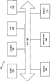
Fig. 7 illustrates for putting into practice the block diagram of the suitable computing environment of various embodiment described herein.
Fig. 8 is the block diagram illustrating according to the routing device of various embodiment.
Embodiment
As provided here, method, apparatus and system have realized the redundant connectivity between private virtual lan business (VPLS) network and Ethernet automatic protection switching (EAPS) network.More specifically, the attached of a plurality of activities to VPLS network is provided in various embodiments.
Fig. 1 is the block diagram illustrating according to the VPLS-EAPS configuration of various embodiment.As used herein, VPLS-EAPS configuration relates to a plurality of attachment point between VPLS network and EAPS network, and these are attached at is movable under normal circumstances.As shown, VPLS core node 110,112,114 and 116 is linked via pseudo-line.As used herein, link refers to transmit any circuit or the channel of data thereon.Here the pseudo-line used refers to imitate for crossing over packet switching network the mechanism of various networkings or telecommunications service, such as those mechanism of using Ethernet, Internet Protocol (IP), label switched path (LSP) and/or multiprotocol label switching (MPLS) etc.The service of imitating can comprise T1 leased line, frame relay, Ethernet, asynchronous transfer mode (Asynchronous Transfer Mode) (ATM), time division multiplexing (TDM) or (SONET)/synchronous digital hierarchy of Synchronous Optical Network (Synchronous Optical Networking) (Synchronous Digital Hierarchy) (SDH).As being entitled as, in the RFC 3985 of " Pseudo WireEmulation Edge-to-Edge[PWE3] Architecture (pseudo wire emulation edge-to-edge [PWE3] architecture) ", discussed, pseudo-line only transmits necessary function for imitating following circuit: this circuit has to some concrete service definitions the fidelity that some is required.
As shown in Figure 1, VPLS core node 110 and 112 is attached to EAPS access ring.Not to make core node 110 or 112 play the effect of EAPS host node, but distribution node 124 is appointed as to host node.When network failure is detected on ring, the host node in EAPS system receives the control message of controlling on VLAN, and this control message has been indicated network failure.In the normal operation period, host node stops protected data vlan business through its secondary ports.During network failure, host node is to its secondary ports unblocking (unblock), and makes protected data vlan business through its secondary ports.Once fault is repaired, secondary ports is just blocked again.In various embodiments, not that any node VPLS node, in EAPS ring all can be designated as EAPS host node.In various embodiments, the VPLS core node that is attached to EAPS ring plays respectively the effect of EAPS controller and partner node.In Fig. 1, core node 110 plays the effect of controller node, and core node 112 plays the effect of partner node simultaneously.EAPS controller node (for example core node 110) comprises controller state machine, whether addressable two the attached VPLS nodes of EAPS node (for example core node 110 and 112) on this controller state machine tracking loop.
In various embodiments, when VPLS customer VLAN (or VMAN) is attached to EAPS ring, as shown in Figure 1, the EAPS ring plate section between core node 110 and 112 is removed, and with the pseudo-line being conducive between node 110 and 112, connects.Here the term that used " shared link " refers to the specific EAPS link of conventionally sharing among a plurality of EAPS rings.Although shared link is shared among a plurality of EAPS ring of being everlasting, shared link also can be for single EAPS ring and maintained.Port Management among auxiliary a plurality of EAPS rings, the function being associated with shared link and/or mechanism (such as controller node state machine etc.) can be used to help communicating by letter between management EAPS and VPLS.EAPS host node (for example node 124) may not have or reception changes relevant any information with the connection between core node 110 and 112.Yet, to suppose to connect change and need to be configured in the VLAN being protected by EAPS that only has a port on ring, core node 110 has with the EAPS function on 112 information changing about being connected really.It should be noted that this configuration does not change EAPS and controls VLAN---EAPS ring remains complete, and EAPS host node (for example node 124) still blocks client and accesses the port on VLAN when ring is intact.
Fig. 2 illustrates the example of link failure, is in the case between node 122 and 124.From connective viewpoint, the various embodiment of VPLS-EAPS configuration have suitably processed the access ring fault as the link failure shown in Fig. 2.When EAPS host node (such as node 124) (such as the linkdown notification due to from node on the ring, hello overtime etc. and) while topology change being detected, on protected VLAN, host node is to its secondary ports unblocking.(compared to Figure 1) the unique difference in Fig. 2 is that link failure and the unblocking to the secondary ports of host node subsequently make node 124 via core node 112 rather than via core node 110, be connected to now VPLS network.Therefore, connectedness is resumed.
When the shared link between core node 110 and 112 breaks down, connectivity recovery sight (scenario) changes.As shown in Figure 3, when shared link breaks down, EAPS host node (for example node 124) is again to its secondary ports unblocking (it is done when there is fault on access ring).Yet when this situation occurs, two VPLS core nodes (being node 110 and 112) all may receive the copy that destination is not any business of the node on EAPS access ring.For example, if the shared link between core node 110 and 112 breaks down and distribution node 126 is just attempting to send grouping to VPLS core node 116, core node 110 and 112 each can receive the copy of grouping.This can cause the grouping of repetition to be sent in VPLS network.In addition, suppose and can utilize different path (for example, via the path from node 112 to node 116 to node 114 to node 110) to re-establish the pseudo-line core node 110 and 112, this sight can cause the traffic loops on EAPS access ring and enter the storm (storm) in VPLS network.For anti-sight here occurs, when the shared link between core node 110 and 112 breaks down, VPLS core node 110 (playing the effect of EAPS controller node) takes to remove and/or deactivate the action of all pseudo-lines that are associated with core node 110.In Fig. 3, can see the removal of pseudo-line.Once pseudo-line has been removed and/or is invalid, all business of advancing between EAPS Access Network and VPLS network are all passed through VPLS core node 112.When core node 110 (being controller node) detects shared link between node 110 and 112 and is repaired, pseudo-line is re-established.
When core node 110 is removed its pseudo-line, core node 110 also for example, signals to inform that their pseudo-lines are no longer movable to its VPLS peer-to-peer (peer) (VPLS core node 114,116 and 112).In certain embodiments, this signaling realizes by fully cancelling pseudo-line.In other embodiments, signaling realizes by " standby " state of the pseudo-line of indication.
Fig. 4 is illustrated in shared link (being the link between node 110 and 112) and access ring (for example, between node 122 and the 124) link failure on the two.In suchlike pair of failure scenario, unlike the sight that only shared link breaks down, VPLS core node 110 and 112 does not receive the copy of ring business.For example, in Fig. 4, in this pair of failure scenario, unique path of distribution node 122 to VPLS networks is by core node 110.Similarly, unique path of distribution node 128 to VPLS networks is by core node 112.Therefore, at one of faulty link, be in two failure scenarios of VPLS core shared link, core node 110 maintains its pseudo-line rather than removal and/or deactivates pseudo-line.
Fig. 5 illustrates a plurality of parallel EAPS access ring that is attached to VPLS core network.As shown, each EAPS ring is not only attached to core node 210 but also be attached to core node 212.Each EAPS ring is shared the link (being shared link) between node 210 and node 212.The function being associated with shared link and/or mechanism management and/or maintenance can be to the EAPS topology informations of VPLS Internet communication.Here, as long as any parallel EAPS ring is complete, just exist the path of two core VPLS nodes---in the case, these two core VPLS nodes are node 210 and 212.When the shared link between node 210 and 212 is during in (shown) malfunction, the EAPS host node on each ring is to its secondary ports unblocking.For the inner EAPS ring of two shown in Fig. 5, this does not cause problem, because each in these rings has the other link failure on ring, this other link failure has prevented that the node in these rings has to the path of two VPLS core nodes (being node 210 and 212).Yet outside ring does not have other link failure.Therefore, the distribution node on the ring of this outside (for example 250,252,254 and 256) has really to the path of two VPLS nodes 210 and 212.It should be noted that two VPLS nodes are still to all access ring execution L2 exchanges.Therefore, all nodes on all three rings all have to the path of two VPLS nodes.As discussed above, the path of encircling two core nodes VPLS network from EAPS can cause access ring loop and/or VPLS storm.Therefore, in thering is the embodiment of the parallel EAPS ring that is attached to VPLS core, in the situation that any parallel EAPS ring be all complete or " good " (for example, without link failure) and shared link be fault and time, controller node (for example core node 210) must make all pseudo-line that is associated with controller node invalid.If all parallel EAPS rings are all for example, in malfunction or " bad " (, upper at least one faulty link of each ring), controller node (for example node 210) is no matter how the state of shared link all maintains its whole existing pseudo-line.Following table shows the recovery action that will take controller node in various embodiments:
Table 1

In various embodiments, the topological change on (one or more) access ring or VPLS network may cause for arriving the change in (one or more) path of customer equipment.For example, in Fig. 2, distribution node 124 can adopt change after the fault on the access ring of the path of other parts the to arrive VPLS network link between node 122 and 124.Before the fault of this link, node 124 arrives VPLS network via core node 110.After fault, node 124 is via core node 112 access VPLS networks.
When EAPS host node (such as the node 124 in Fig. 1, the node 222 in Fig. 5 etc.) detects topology change, it sends " refreshing (flush) FDB " message to its other transfers (transit) node (i.e. other nodes on ring).In certain embodiments, refresh message is relearned the MAC Address of ring on each node in ring.Suppose that refresh message is the EAPS message of propagating to other nodes that encircle, refresh message is not propagated inherently on VPLS network.In addition, the attached of long-range VPLS Nodes can not used EAPS.Utilize above example, VPLS node 114 (Fig. 2) will be expected and found node 124 via the pseudo-line between VPLS node 114 and VPLS node 110.Yet, once there is the link failure between node 122 and 124, at VPLS node 114, do not discover topology change and be configured in the situation that send business on the path by faulty link, any business sending to node 124 from VPLS node 114 via VPLS node 110 will can not arrive its destination.In order to overcome this problem, EAPS for example, informs any EAPS receiving message that " refreshes FDB " to VPLS controller and partner node (node 110 and 112) are upper.Then controller and partner node can propagate this information, so that other VPLS nodes can refresh they forwarding databases (such as MAC Address etc.) separately.For example, suppose that MAC Address for example, from specific initiation node study next (, VPLS node 116 is from the MAC Address of VPLS node 112 study nodes 128), controller and partner node are all informed any topology change to other VPLS nodes.
Fig. 6 is the flow chart illustrating for the processing of the redundant connectivity between VPLS network and EAPS network.Two VPLS nodes are set up 310, to play respectively the effect of EAPS controller node and partner node.Two VPLS nodes link by the pseudo-line across EAPS shared link.Other EAPS node is also set up 320.Other EAPS node links each other, and in other EAPS node one is designated as host node.Link is also set up between VPLS node and EAPS node, so that one or more EAPS ring is formed 330.Each EAPS ring comprises the shared link between the first and second VPLS nodes.EAPS encircles monitored 340 to detect link failure.When the fault of the pseudo-line shared link between the first and second VPLS nodes is detected 350, determine that 360 whether any EAPS nodes have to the path of these two VPLS nodes.If so, make all pseudo-line invalid 370 that is associated with controller node.If not, maintain the 380 existing pseudo-wired link that are associated with a VPLS node.
Fig. 7 illustrates for putting into practice the block diagram of the suitable computing environment of various embodiment described herein.Jointly, wish that these assemblies represent various types of other hardware system, include but not limited to general-purpose computing system and the special network switch.
The various assemblies of computer system 700 can be re-arranged in various embodiments, and some embodiment can neither need also not comprise all above assemblies.In addition, extra assembly can be included in system 700, for example extra processor (for example digital signal processor), memory device, memory, network/communication interface etc.
In the illustrative embodiments of Fig. 7, for the present invention based on the above discussion, between EAPS network and VPLS network, provide the method and apparatus of redundant connectivity can be implemented as a series of software routines by computer system 700 operations of Fig. 7.These software routines comprise will be by a plurality of instructions or a series of instruction carried out such as treatment system processor 710, in hardware system.At first, the instruction of series is for example stored in, on (, in routing manager database) data storage device 760, memory 720 or flash memory 730.
Fig. 8 illustrates the various assemblies of available routing device in various embodiments.Routing device 810 comprises VPLS control assembly 812, pseudo-line (PW) control assembly 814, EAPS control assembly 816 and bridge control assembly 818.The auxiliary complete VPLS that comprises a plurality of PW that sets up of VPLS control assembly 812.PW control assembly 814 is set up other PW, and PW state information is signaled to peer-to-peer.EAPS control assembly 816 monitors and controls EAPS operation.Bridge control assembly 818 monitors and controls normal L2 bridge operation.EAPS control assembly 816 provides function and the information relevant with EAPS ring state connective and EAPS shared link to VPLS control 812 and/or PW control 814.VPLS forwarding logic assembly 820, PW forwarding logic assembly 822 and bridge forwarding component 824 combine and divide into groups with forwarding data between PW and VPLS client.These forwarding components are coupled via bus 826.Logic based on these assemblies is carried out route to business on routing device port 828.For example, routing device 810 is the examples that can be used for VPLS core node 110 and/or 112 the routing device of Fig. 2.
Various assembly described herein can be for carrying out the device of function described herein.Each assembly described herein comprises software, hardware or their combination.Assembly can be implemented as software module, hardware module, specialized hardware (such as specialized hardware, application-specific integrated circuit (ASIC) (ASIC), digital signal processor (DSP) etc.), embedded controller, hard-wired circuit, etc.Software content (for example data, instruction, configuration) can provide via the manufacture (article ofmanufacture) that comprises computer-readable medium, and computer-readable medium provides the content that represents executable instruction.This content can make computer carry out various function/operations described herein.Computer-readable medium comprises in the addressable mode of computing equipment (such as computer, PDA, electronic system etc.) provides any mechanism of (store and/or transmit) information, recordable/not recordable medium (for example, read-only memory (ROM), random access memory (RAM), magnetic disk storage medium, optical storage media, flash memory device etc.) for example.This content can be directly executable (" object " or " executable " form), source code etc.Computer-readable medium also can comprise can be from storage device or the database of its downloading contents.Computer-readable medium also can be included in the meaningful equipment being stored thereon or product when selling or paying.Therefore, pay and there is the equipment of stored content or provide content can be understood to provide the manufacture with such content described herein for downloading by communication media.
Except described herein, in the situation that do not depart from the scope of disclosed embodiment of the present invention and implementation, can carry out various modifications to disclosed embodiment of the present invention and implementation.Therefore, should understand diagram and example here with exemplary and nonrestrictive meaning.Should only with reference to claims, weigh scope of the present invention.
Claims (21)
1. provide the redundancy of private virtual lan business VPLS network is accessed to provide the connective method between Ethernet automatic protection switching EAPS Access Network and VPLS network, described method comprises:
A VPLS node in a plurality of VPLS nodes is set to play the effect of EAPS controller node;
The 2nd VPLS node in a plurality of VPLS nodes is set to play the effect of EAPS partner node, comprising a described VPLS node and described the 2nd VPLS node, at interior described a plurality of VPLS nodes, by pseudo-wired link, link each other, and a described VPLS node and described the 2nd VPLS node link each other by EAPS shared link;
Set up the EAPS ring of coupling a described VPLS node, described the 2nd VPLS node and a plurality of EAPS nodes;
Detect the network failure of the described EAPS shared link between a described VPLS node and described the 2nd VPLS node;
Any EAPS node in response to described fault being detected in described a plurality of EAPS nodes makes all pseudo-wired link that is associated with a described VPLS node invalid while having to the two path of a described VPLS node and described the 2nd VPLS node; And
Any EAPS node in response to described fault being detected in described a plurality of EAPS nodes maintains the existing pseudo-wired link being associated with a described VPLS node while lacking the two path of a described VPLS node and described the 2nd VPLS node.
2. method according to claim 1, a wherein said VPLS node and described the 2nd VPLS node are movable under normal circumstances, a wherein said VPLS node comprises controller state machine, and described controller state machine is for following the tracks of the whether addressable described VPLS node of each EAPS node of described a plurality of EAPS nodes and described the 2nd VPLS node.
3. method according to claim 1, also comprises:
Monitor described EAPS ring; And
In response to the network failure detecting on monitored EAPS ring, and the forwarding database address on described a plurality of VPLS nodes is refreshed.
4. method according to claim 1, wherein makes all pseudo-wired link that is associated with a described VPLS node transmit the indication to the pseudo-wired link being disabled invalid also comprising to VPLS nodes in described a plurality of VPLS nodes, that be coupled via pseudo-wired link and a described VPLS node.
5. method according to claim 1, the pseudo-wired link between a wherein said VPLS node and described the 2nd VPLS node has replaced the client virtual local area network (LAN) of part.
6. method according to claim 1, one of wherein said a plurality of EAPS nodes are designated as host node, and this host node is for receiving the control message of the network failure of the described EAPS ring of indication.
7. method according to claim 6 also comprises:
The secondary ports that stops in the normal operation period described host node; And
Secondary ports unblocking in response to described network failure being detected to described host node.
8. method according to claim 1 also comprises when a described VPLS node detects and when shared link between VPLS node is repaired, re-establishes the pseudo-wired link between VPLS node.
9. method according to claim 1, wherein said EAPS Access Network comprises a plurality of EAPS rings, and wherein said shared link is shared between described a plurality of EAPS rings.
10. method according to claim 9, wherein play described EAPS controller node effect a described VPLS node for:
Any when described shared link fault and in described a plurality of parallel ring encircled and made when complete all pseudo-wired link that is associated with a described VPLS node invalid, and when described a plurality of parallel EAPS encircle whole fault, maintains all existing pseudo-wired link.
11. 1 kinds provide the redundancy of private virtual lan business VPLS network are accessed to provide the connective system between Ethernet automatic protection switching EAPS Access Network and VPLS network, and described system comprises:
A VPLS node that is used for a plurality of VPLS nodes are set is to play the device of the effect of EAPS controller node;
The 2nd VPLS node that is used for a plurality of VPLS nodes are set is to play the device of the effect of EAPS partner node, comprising a described VPLS node and described the 2nd VPLS node, at interior described a plurality of VPLS nodes, by pseudo-wired link PW, come each other via port link, and a described VPLS node and described the 2nd VPLS node come each other via port link by EAPS shared link;
For setting up the device of the EAPS ring of coupling a described VPLS node, described the 2nd VPLS node and a plurality of EAPS nodes;
Device for detection of the network failure of the described EAPS shared link between a described VPLS node and described the 2nd VPLS node;
For the invalid device of all pseudo-wired link that makes when any EAPS node of described a plurality of EAPS nodes has to the two path of a described VPLS node and described the 2nd VPLS node in response to described fault being detected to be associated with a described VPLS node; And
For maintain the device of the existing pseudo-wired link being associated with a described VPLS node when any EAPS node of described a plurality of EAPS nodes lacks the two path of a described VPLS node and described the 2nd VPLS node in response to described fault being detected.
12. systems according to claim 11 also comprise that a wherein said VPLS node and described the 2nd VPLS node are movable under normal circumstances for monitoring the device of described EAPS ring.
13. systems according to claim 11, each the VPLS node in wherein said a plurality of VPLS nodes comprises for forwarding the packet client's of VPLS forwarding logic assembly.
14. systems according to claim 11, each VPLS node in wherein said a plurality of VPLS node comprises the pseudo-line traffic control logic of indicating the state of pseudo-wired link for the VPLS node to described a plurality of VPLS nodes, and wherein said a plurality of VPLS nodes are coupled to pseudo-wired link via port.
15. systems according to claim 11, wherein said EAPS Access Network comprises a plurality of EAPS rings, and wherein said shared link is shared between described a plurality of EAPS rings.
16. systems according to claim 15, wherein play described EAPS controller node effect a described VPLS node for:
Any when described shared link fault and in described a plurality of parallel ring encircled and made when complete all pseudo-wired link that is associated with a described VPLS node invalid, and when described a plurality of parallel EAPS encircle whole fault, maintains all existing pseudo-wired link.
17. 1 kinds for providing the method for the redundant connectivity between Ethernet automatic protection switching EAPS Access Network and private virtual lan business VPLS network, and described method comprises:
Setting is from a VPLS node and the 2nd VPLS node of a plurality of VPLS nodes, described a plurality of VPLS node links each other by pseudo-wired link, and a wherein said VPLS node and described the 2nd VPLS node link each other by EAPS shared link;
The EAPS ring that foundation is coupled a described VPLS node and described the 2nd VPLS node and a plurality of EAPS node;
Detect dual network fault, described dual network fault comprises the fault of the EAPS shared link between a described VPLS node and described the 2nd VPLS node, and the copy of the business on EAPS Access Network described in a described VPLS node and described the 2nd VPLS node loss; And
In response to described dual network fault being detected, maintain all pseudo-wired link being associated with a described VPLS node.
18. methods according to claim 17, also comprise:
Detect the only network failure of the described EAPS shared link between a described VPLS node and described the 2nd VPLS node; And
In response to the network failure of described EAPS shared link only being detected and any EAPS node in described a plurality of EAPS nodes makes while having to the two path of a described VPLS node and described the 2nd VPLS node all pseudo-wired link that is associated with a described VPLS node invalid.
19. methods according to claim 17, a wherein said VPLS node plays EAPS controller node, and wherein said the 2nd VPLS node plays EAPS partner node.
20. 1 kinds for providing the method for the redundant connectivity between Ethernet automatic protection switching EAPS Access Network and private virtual lan business VPLS network, and described method comprises:
Setting is from a VPLS node and the 2nd VPLS node of a plurality of VPLS nodes, described a plurality of VPLS node links each other by pseudo-wired link, and a wherein said VPLS node and described the 2nd VPLS node link each other by EAPS shared link;
A plurality of parallel EAPS ring that foundation is coupled a described VPLS node and described the 2nd VPLS node and a plurality of EAPS node, wherein said shared link is shared between described a plurality of parallel EAPS rings; And
Any when described shared link fault and in described a plurality of parallel EAPS ring encircled when complete, makes all pseudo-wired link that is associated with a described VPLS node invalid.
21. methods according to claim 20, a wherein said VPLS node plays the work of EAPS controller node in order to maintain all existing pseudo-lines when described a plurality of parallel EAPS encircle whole fault, and wherein said the 2nd VPLS node plays EAPS partner node.
Applications Claiming Priority (3)
| Application Number | Priority Date | Filing Date | Title |
|---|---|---|---|
| US12/101,603 | 2008-04-11 | ||
| US12/101,603 US7990850B2 (en) | 2008-04-11 | 2008-04-11 | Redundant Ethernet automatic protection switching access to virtual private LAN services |
| PCT/US2009/036548 WO2009126390A1 (en) | 2008-04-11 | 2009-03-09 | Redundant ethernet automatic protection switching access to virtual private lan services |
Publications (2)
| Publication Number | Publication Date |
|---|---|
| CN101999224A CN101999224A (en) | 2011-03-30 |
| CN101999224B true CN101999224B (en) | 2014-01-29 |
Family
ID=40589747
Family Applications (1)
| Application Number | Title | Priority Date | Filing Date |
|---|---|---|---|
| CN200980112834.9A Active CN101999224B (en) | 2008-04-11 | 2009-03-09 | Redundant Ethernet automatic protection switching access to virtual private lan services |
Country Status (5)
| Country | Link |
|---|---|
| US (4) | US7990850B2 (en) |
| EP (2) | EP2277290B9 (en) |
| JP (1) | JP5548673B2 (en) |
| CN (1) | CN101999224B (en) |
| WO (1) | WO2009126390A1 (en) |
Families Citing this family (38)
| Publication number | Priority date | Publication date | Assignee | Title |
|---|---|---|---|---|
| CN101534233A (en) * | 2008-03-12 | 2009-09-16 | 中兴通讯股份有限公司 | Method for updating Ethernet ring network node address table |
| US7990850B2 (en) | 2008-04-11 | 2011-08-02 | Extreme Networks, Inc. | Redundant Ethernet automatic protection switching access to virtual private LAN services |
| US20100226245A1 (en) * | 2009-02-16 | 2010-09-09 | Jeong-Dong Ryoo | Method and apparatus for protection switching in ring network |
| JP5168230B2 (en) * | 2009-05-26 | 2013-03-21 | 富士通株式会社 | Communication system, edge router, and signal transfer method |
| CN101789903B (en) * | 2009-12-30 | 2012-05-23 | 华为技术有限公司 | Method, device and system for protecting semi-ring network |
| EP2553882B1 (en) | 2010-03-30 | 2014-07-16 | Telefonaktiebolaget LM Ericsson (publ) | Method for protecting an ethernet ring from a superloop going through the ethernet ring |
| EP2553881B1 (en) * | 2010-03-30 | 2015-01-21 | Telefonaktiebolaget LM Ericsson (publ) | Method for protection against superloops in an ethernet ring |
| CN102377626A (en) * | 2010-08-19 | 2012-03-14 | 盛科网络(苏州)有限公司 | Dual-homing-supporting ring networking method based on virtual private local area network service (VPLS) and Ethernet automatic protection switching (EAPS) |
| US9813257B2 (en) * | 2010-09-10 | 2017-11-07 | Extreme Networks, Inc. | Access network dual path connectivity |
| US9164806B2 (en) | 2011-01-28 | 2015-10-20 | Oracle International Corporation | Processing pattern framework for dispatching and executing tasks in a distributed computing grid |
| US9201685B2 (en) | 2011-01-28 | 2015-12-01 | Oracle International Corporation | Transactional cache versioning and storage in a distributed data grid |
| US9063787B2 (en) | 2011-01-28 | 2015-06-23 | Oracle International Corporation | System and method for using cluster level quorum to prevent split brain scenario in a data grid cluster |
| US9063852B2 (en) * | 2011-01-28 | 2015-06-23 | Oracle International Corporation | System and method for use with a data grid cluster to support death detection |
| US9081839B2 (en) | 2011-01-28 | 2015-07-14 | Oracle International Corporation | Push replication for use with a distributed data grid |
| CN103023771A (en) * | 2011-09-28 | 2013-04-03 | 华为技术有限公司 | Method and device for processing fault of ring topological network and routing equipment |
| CN102510354A (en) * | 2011-12-15 | 2012-06-20 | 盛科网络(苏州)有限公司 | Dual-home-supported ring network method and system based on virtual private local area network (LAN) service (VPLS) and G8032 |
| US10706021B2 (en) | 2012-01-17 | 2020-07-07 | Oracle International Corporation | System and method for supporting persistence partition discovery in a distributed data grid |
| CN102857379B (en) * | 2012-09-18 | 2016-08-03 | 中兴通讯股份有限公司 | The protection control method of ethernet ring network inter-node connectivity, device and primary nodal point |
| GB2508355B (en) * | 2012-11-28 | 2021-02-17 | Nomad Digital Ltd | Communication method |
| CN103200172B (en) | 2013-02-19 | 2018-06-26 | 中兴通讯股份有限公司 | A kind of method and system of 802.1X accesses session keepalive |
| WO2014146271A1 (en) * | 2013-03-21 | 2014-09-25 | 华为技术有限公司 | Transmission apparatus, connecting mechanism and method |
| US9319240B2 (en) * | 2013-09-24 | 2016-04-19 | Ciena Corporation | Ethernet Ring Protection node |
| US9225629B2 (en) * | 2014-05-30 | 2015-12-29 | Telefonaktiebolaget L M Ericsson (Publ) | Efficient identification of node protection remote LFA target |
| US10664495B2 (en) | 2014-09-25 | 2020-05-26 | Oracle International Corporation | System and method for supporting data grid snapshot and federation |
| CN105991188B (en) | 2015-02-16 | 2019-09-10 | 阿里巴巴集团控股有限公司 | A kind of method and device detecting sharing memory |
| US10798146B2 (en) | 2015-07-01 | 2020-10-06 | Oracle International Corporation | System and method for universal timeout in a distributed computing environment |
| US11163498B2 (en) | 2015-07-01 | 2021-11-02 | Oracle International Corporation | System and method for rare copy-on-write in a distributed computing environment |
| US10585599B2 (en) | 2015-07-01 | 2020-03-10 | Oracle International Corporation | System and method for distributed persistent store archival and retrieval in a distributed computing environment |
| US10860378B2 (en) | 2015-07-01 | 2020-12-08 | Oracle International Corporation | System and method for association aware executor service in a distributed computing environment |
| AT517779B1 (en) * | 2015-10-01 | 2021-10-15 | B & R Ind Automation Gmbh | Method for cross-traffic between two slaves in a ring-shaped data network |
| JP2017079399A (en) * | 2015-10-20 | 2017-04-27 | 富士通株式会社 | Transmission device and transmission system |
| US11550820B2 (en) | 2017-04-28 | 2023-01-10 | Oracle International Corporation | System and method for partition-scoped snapshot creation in a distributed data computing environment |
| US10769019B2 (en) | 2017-07-19 | 2020-09-08 | Oracle International Corporation | System and method for data recovery in a distributed data computing environment implementing active persistence |
| US20190044848A1 (en) * | 2017-08-01 | 2019-02-07 | Hewlett Packard Enterprise Development Lp | Virtual switching framework |
| US10721095B2 (en) | 2017-09-26 | 2020-07-21 | Oracle International Corporation | Virtual interface system and method for multi-tenant cloud networking |
| US10862965B2 (en) | 2017-10-01 | 2020-12-08 | Oracle International Corporation | System and method for topics implementation in a distributed data computing environment |
| JP7183853B2 (en) * | 2019-02-15 | 2022-12-06 | 日本電信電話株式会社 | NETWORK DEVICE, NETWORK SYSTEM, NETWORK CONNECTION METHOD, AND PROGRAM |
| CN110519148B (en) * | 2019-07-25 | 2022-01-18 | 深圳震有科技股份有限公司 | Method, system and storage medium for establishing VPN channel by multilink backup |
Citations (1)
| Publication number | Priority date | Publication date | Assignee | Title |
|---|---|---|---|---|
| CN101014035A (en) * | 2007-02-05 | 2007-08-08 | 华为技术有限公司 | Reliability processing method and system of multi-service networking provided by metro Ethernet |
Family Cites Families (15)
| Publication number | Priority date | Publication date | Assignee | Title |
|---|---|---|---|---|
| US7106729B1 (en) * | 2001-10-29 | 2006-09-12 | Ciena Corporation | Switching control mechanism based upon the logical partitioning of a switch element |
| US6766482B1 (en) | 2001-10-31 | 2004-07-20 | Extreme Networks | Ethernet automatic protection switching |
| US7269135B2 (en) | 2002-04-04 | 2007-09-11 | Extreme Networks, Inc. | Methods and systems for providing redundant connectivity across a network using a tunneling protocol |
| JP4020753B2 (en) | 2002-10-25 | 2007-12-12 | 富士通株式会社 | Ring switching method |
| US8520507B1 (en) | 2004-03-08 | 2013-08-27 | Extreme Networks, Inc. | Ethernet automatic protection switching |
| JP4627205B2 (en) | 2005-03-28 | 2011-02-09 | 富士通株式会社 | Ring network system and failure recovery method |
| US7983150B2 (en) | 2006-01-18 | 2011-07-19 | Corrigent Systems Ltd. | VPLS failure protection in ring networks |
| IL176330A0 (en) * | 2006-06-15 | 2007-07-04 | Eci Telecom Ltd | Technique of traffic protection loop-free interconnection for ethernet and/or vpls networks |
| US7626930B2 (en) * | 2006-11-13 | 2009-12-01 | Corrigent Systems Ltd. | Hash-based multi-homing |
| EP2098021A1 (en) | 2006-12-29 | 2009-09-09 | Telefonaktiebolaget Lm Ericsson (publ) | Method of providing data |
| EP1968248B1 (en) * | 2007-03-05 | 2010-06-09 | Alcatel Lucent | Packet ring protection |
| US8964571B2 (en) * | 2007-07-06 | 2015-02-24 | Alcatel Lucent | Method and apparatus for simultaneous support of fast restoration and native multicast in IP networks |
| US7969866B2 (en) * | 2008-03-31 | 2011-06-28 | Telefonaktiebolaget L M Ericsson (Publ) | Hierarchical virtual private LAN service hub connectivity failure recovery |
| US7990850B2 (en) | 2008-04-11 | 2011-08-02 | Extreme Networks, Inc. | Redundant Ethernet automatic protection switching access to virtual private LAN services |
| US8416775B2 (en) * | 2010-05-19 | 2013-04-09 | Juniper Networks, Inc. | Systems and methods for equal-cost multi-path virtual private LAN service |
-
2008
- 2008-04-11 US US12/101,603 patent/US7990850B2/en active Active
-
2009
- 2009-03-09 JP JP2011504028A patent/JP5548673B2/en not_active Expired - Fee Related
- 2009-03-09 CN CN200980112834.9A patent/CN101999224B/en active Active
- 2009-03-09 WO PCT/US2009/036548 patent/WO2009126390A1/en active Application Filing
- 2009-03-09 EP EP09730176.6A patent/EP2277290B9/en active Active
- 2009-03-09 EP EP12173669.8A patent/EP2518954B1/en active Active
-
2011
- 2011-06-21 US US13/165,534 patent/US8797849B2/en active Active
-
2014
- 2014-07-02 US US14/322,643 patent/US9407455B2/en active Active
-
2016
- 2016-06-23 US US15/190,922 patent/US10469366B2/en active Active
Patent Citations (1)
| Publication number | Priority date | Publication date | Assignee | Title |
|---|---|---|---|---|
| CN101014035A (en) * | 2007-02-05 | 2007-08-08 | 华为技术有限公司 | Reliability processing method and system of multi-service networking provided by metro Ethernet |
Also Published As
| Publication number | Publication date |
|---|---|
| US10469366B2 (en) | 2019-11-05 |
| US20160308756A1 (en) | 2016-10-20 |
| WO2009126390A1 (en) | 2009-10-15 |
| CN101999224A (en) | 2011-03-30 |
| US7990850B2 (en) | 2011-08-02 |
| JP2011518506A (en) | 2011-06-23 |
| US20110249552A1 (en) | 2011-10-13 |
| EP2518954A1 (en) | 2012-10-31 |
| JP5548673B2 (en) | 2014-07-16 |
| US20090257348A1 (en) | 2009-10-15 |
| EP2518954B1 (en) | 2018-05-09 |
| EP2277290B9 (en) | 2014-11-19 |
| US9407455B2 (en) | 2016-08-02 |
| US8797849B2 (en) | 2014-08-05 |
| US20140347980A1 (en) | 2014-11-27 |
| EP2277290B1 (en) | 2014-08-13 |
| EP2277290A1 (en) | 2011-01-26 |
Similar Documents
| Publication | Publication Date | Title |
|---|---|---|
| CN101999224B (en) | Redundant Ethernet automatic protection switching access to virtual private lan services | |
| JP4688765B2 (en) | Network redundancy method and intermediate switch device | |
| US9391888B2 (en) | System and method for implementation of layer 2 redundancy protocols across multiple networks | |
| US8724452B2 (en) | Technique for protecting communication traffic in a connection having redundancy | |
| US9509591B2 (en) | Technique for dual homing interconnection between communication networks | |
| EP1958364B1 (en) | Vpls remote failure indication | |
| JP5168230B2 (en) | Communication system, edge router, and signal transfer method | |
| US20130272114A1 (en) | Pseudo wire switching method and device | |
| WO2012028029A1 (en) | Switching method and system | |
| WO2009082825A1 (en) | Interworking an ethernet ring network and an ethernet network with traffic engineered trunks | |
| WO2010124367A1 (en) | Virtual links in a routed ethernet mesh network | |
| CN101582834A (en) | Updating method, equipment and system of forwarding table during service transmission of Ethernet | |
| JPWO2009054032A1 (en) | Communication device in label switching network | |
| WO2010031295A1 (en) | Control method for ethernet failure recovery | |
| CN102957620A (en) | Equipment and method for management of MAC (media access control) address table entries in TRILL (transparent interconnection of lots of links) network | |
| WO2012062097A1 (en) | Multi-ring ethernet network and protection method thereof | |
| WO2010139173A1 (en) | Address refresh method and system | |
| WO2013007124A1 (en) | Method and system for advertising virtual router redundancy protocol link protection | |
| CN101789903A (en) | Method, device and system for protecting semi-ring network | |
| CN102857423A (en) | Service flow transferring method and node in distributed link polymerization system | |
| US9674079B1 (en) | Distribution layer redundancy scheme for coupling geographically dispersed sites | |
| IL191454A (en) | Vpls remote failure indication |
Legal Events
| Date | Code | Title | Description |
|---|---|---|---|
| C06 | Publication | ||
| PB01 | Publication | ||
| C10 | Entry into substantive examination | ||
| SE01 | Entry into force of request for substantive examination | ||
| C14 | Grant of patent or utility model | ||
| GR01 | Patent grant |