EP2224784A1 - Heated area element - Google Patents
Heated area element Download PDFInfo
- Publication number
- EP2224784A1 EP2224784A1 EP10153412A EP10153412A EP2224784A1 EP 2224784 A1 EP2224784 A1 EP 2224784A1 EP 10153412 A EP10153412 A EP 10153412A EP 10153412 A EP10153412 A EP 10153412A EP 2224784 A1 EP2224784 A1 EP 2224784A1
- Authority
- EP
- European Patent Office
- Prior art keywords
- adhesive
- surface element
- layer
- polymer composition
- heating
- Prior art date
- Legal status (The legal status is an assumption and is not a legal conclusion. Google has not performed a legal analysis and makes no representation as to the accuracy of the status listed.)
- Granted
Links
- 229920000642 polymer Polymers 0.000 claims abstract description 246
- 238000010438 heat treatment Methods 0.000 claims abstract description 169
- 239000000853 adhesive Substances 0.000 claims abstract description 116
- 239000004831 Hot glue Substances 0.000 claims abstract description 53
- 239000000758 substrate Substances 0.000 claims abstract description 49
- 239000004820 Pressure-sensitive adhesive Substances 0.000 claims abstract description 47
- OKTJSMMVPCPJKN-UHFFFAOYSA-N Carbon Chemical compound [C] OKTJSMMVPCPJKN-UHFFFAOYSA-N 0.000 claims abstract description 20
- 239000004020 conductor Substances 0.000 claims abstract description 15
- 229920001577 copolymer Polymers 0.000 claims abstract description 14
- 229920000098 polyolefin Polymers 0.000 claims abstract description 13
- 229920001971 elastomer Polymers 0.000 claims abstract description 12
- 239000006229 carbon black Substances 0.000 claims abstract description 9
- 239000000806 elastomer Substances 0.000 claims abstract description 9
- 229920003023 plastic Polymers 0.000 claims abstract description 9
- 239000004033 plastic Substances 0.000 claims abstract description 9
- 239000004952 Polyamide Substances 0.000 claims abstract description 8
- 229920003052 natural elastomer Polymers 0.000 claims abstract description 8
- 229920001194 natural rubber Polymers 0.000 claims abstract description 8
- 229920006132 styrene block copolymer Polymers 0.000 claims abstract description 8
- 229920001400 block copolymer Polymers 0.000 claims abstract description 7
- 229910002804 graphite Inorganic materials 0.000 claims abstract description 7
- 239000010439 graphite Substances 0.000 claims abstract description 7
- 244000043261 Hevea brasiliensis Species 0.000 claims abstract description 6
- 150000001252 acrylic acid derivatives Chemical class 0.000 claims abstract description 6
- 150000002734 metacrylic acid derivatives Chemical class 0.000 claims abstract description 6
- 229920002635 polyurethane Polymers 0.000 claims abstract description 6
- 239000004814 polyurethane Substances 0.000 claims abstract description 6
- 229920003051 synthetic elastomer Polymers 0.000 claims abstract description 6
- 239000005061 synthetic rubber Substances 0.000 claims abstract description 6
- 229920000554 ionomer Polymers 0.000 claims abstract description 5
- 229920001296 polysiloxane Polymers 0.000 claims abstract description 5
- 239000011852 carbon nanoparticle Substances 0.000 claims abstract description 4
- 239000004433 Thermoplastic polyurethane Substances 0.000 claims abstract description 3
- 229920002803 thermoplastic polyurethane Polymers 0.000 claims abstract description 3
- 239000002923 metal particle Substances 0.000 claims abstract 2
- 239000000203 mixture Substances 0.000 claims description 218
- 239000011231 conductive filler Substances 0.000 claims description 30
- 239000002131 composite material Substances 0.000 claims description 13
- 229920006345 thermoplastic polyamide Polymers 0.000 claims 1
- 239000000463 material Substances 0.000 abstract description 42
- 239000000945 filler Substances 0.000 abstract description 22
- 229920002647 polyamide Polymers 0.000 abstract description 7
- VNWKTOKETHGBQD-UHFFFAOYSA-N methane Chemical compound C VNWKTOKETHGBQD-UHFFFAOYSA-N 0.000 abstract 1
- 239000010410 layer Substances 0.000 description 217
- 230000001070 adhesive effect Effects 0.000 description 81
- 238000012360 testing method Methods 0.000 description 29
- 230000000694 effects Effects 0.000 description 28
- 238000000034 method Methods 0.000 description 24
- 239000000178 monomer Substances 0.000 description 21
- 229920005601 base polymer Polymers 0.000 description 19
- 238000004132 cross linking Methods 0.000 description 17
- 230000008569 process Effects 0.000 description 17
- -1 chloropolymers Polymers 0.000 description 16
- 239000011521 glass Substances 0.000 description 16
- 239000012790 adhesive layer Substances 0.000 description 15
- 239000002585 base Substances 0.000 description 15
- 239000000976 ink Substances 0.000 description 14
- 229920005989 resin Polymers 0.000 description 14
- 239000011347 resin Substances 0.000 description 14
- NIXOWILDQLNWCW-UHFFFAOYSA-N 2-Propenoic acid Natural products OC(=O)C=C NIXOWILDQLNWCW-UHFFFAOYSA-N 0.000 description 12
- 239000000654 additive Substances 0.000 description 12
- 150000001875 compounds Chemical class 0.000 description 12
- 238000005259 measurement Methods 0.000 description 12
- 230000000052 comparative effect Effects 0.000 description 10
- 239000013615 primer Substances 0.000 description 10
- 239000002987 primer (paints) Substances 0.000 description 10
- PPBRXRYQALVLMV-UHFFFAOYSA-N Styrene Chemical compound C=CC1=CC=CC=C1 PPBRXRYQALVLMV-UHFFFAOYSA-N 0.000 description 9
- 239000005038 ethylene vinyl acetate Substances 0.000 description 9
- 229920001200 poly(ethylene-vinyl acetate) Polymers 0.000 description 9
- 239000000126 substance Substances 0.000 description 9
- BQCADISMDOOEFD-UHFFFAOYSA-N Silver Chemical compound [Ag] BQCADISMDOOEFD-UHFFFAOYSA-N 0.000 description 8
- 238000010894 electron beam technology Methods 0.000 description 8
- 230000001965 increasing effect Effects 0.000 description 8
- 229910052709 silver Inorganic materials 0.000 description 8
- 239000004332 silver Substances 0.000 description 8
- 230000008901 benefit Effects 0.000 description 7
- 239000002041 carbon nanotube Substances 0.000 description 7
- 229910021393 carbon nanotube Inorganic materials 0.000 description 7
- 229920001940 conductive polymer Polymers 0.000 description 7
- 230000007423 decrease Effects 0.000 description 7
- 230000020169 heat generation Effects 0.000 description 7
- 238000004519 manufacturing process Methods 0.000 description 7
- 239000004014 plasticizer Substances 0.000 description 7
- BAPJBEWLBFYGME-UHFFFAOYSA-N Methyl acrylate Chemical compound COC(=O)C=C BAPJBEWLBFYGME-UHFFFAOYSA-N 0.000 description 6
- DQXBYHZEEUGOBF-UHFFFAOYSA-N but-3-enoic acid;ethene Chemical compound C=C.OC(=O)CC=C DQXBYHZEEUGOBF-UHFFFAOYSA-N 0.000 description 6
- 235000019241 carbon black Nutrition 0.000 description 6
- 230000008859 change Effects 0.000 description 6
- 238000006243 chemical reaction Methods 0.000 description 6
- 238000013461 design Methods 0.000 description 6
- 238000002844 melting Methods 0.000 description 6
- 229920006126 semicrystalline polymer Polymers 0.000 description 6
- 239000013032 Hydrocarbon resin Substances 0.000 description 5
- 239000004698 Polyethylene Substances 0.000 description 5
- XTXRWKRVRITETP-UHFFFAOYSA-N Vinyl acetate Chemical compound CC(=O)OC=C XTXRWKRVRITETP-UHFFFAOYSA-N 0.000 description 5
- 150000002148 esters Chemical class 0.000 description 5
- 238000011049 filling Methods 0.000 description 5
- 230000006870 function Effects 0.000 description 5
- 230000009477 glass transition Effects 0.000 description 5
- 229920006270 hydrocarbon resin Polymers 0.000 description 5
- 230000008018 melting Effects 0.000 description 5
- 239000000049 pigment Substances 0.000 description 5
- 230000035882 stress Effects 0.000 description 5
- 239000004753 textile Substances 0.000 description 5
- 229920001169 thermoplastic Polymers 0.000 description 5
- SOGAXMICEFXMKE-UHFFFAOYSA-N Butylmethacrylate Chemical compound CCCCOC(=O)C(C)=C SOGAXMICEFXMKE-UHFFFAOYSA-N 0.000 description 4
- 239000004971 Cross linker Substances 0.000 description 4
- GWEVSGVZZGPLCZ-UHFFFAOYSA-N Titan oxide Chemical compound O=[Ti]=O GWEVSGVZZGPLCZ-UHFFFAOYSA-N 0.000 description 4
- 239000013543 active substance Substances 0.000 description 4
- 239000002390 adhesive tape Substances 0.000 description 4
- 229910052782 aluminium Inorganic materials 0.000 description 4
- XAGFODPZIPBFFR-UHFFFAOYSA-N aluminium Chemical compound [Al] XAGFODPZIPBFFR-UHFFFAOYSA-N 0.000 description 4
- 125000003118 aryl group Chemical group 0.000 description 4
- CQEYYJKEWSMYFG-UHFFFAOYSA-N butyl acrylate Chemical compound CCCCOC(=O)C=C CQEYYJKEWSMYFG-UHFFFAOYSA-N 0.000 description 4
- 238000011161 development Methods 0.000 description 4
- 230000018109 developmental process Effects 0.000 description 4
- 238000009826 distribution Methods 0.000 description 4
- 239000004744 fabric Substances 0.000 description 4
- 238000009472 formulation Methods 0.000 description 4
- 239000007788 liquid Substances 0.000 description 4
- 239000011159 matrix material Substances 0.000 description 4
- 229910052751 metal Inorganic materials 0.000 description 4
- 239000002184 metal Substances 0.000 description 4
- TWNQGVIAIRXVLR-UHFFFAOYSA-N oxo(oxoalumanyloxy)alumane Chemical compound O=[Al]O[Al]=O TWNQGVIAIRXVLR-UHFFFAOYSA-N 0.000 description 4
- 239000000123 paper Substances 0.000 description 4
- 238000006116 polymerization reaction Methods 0.000 description 4
- 239000002904 solvent Substances 0.000 description 4
- 125000000391 vinyl group Chemical group [H]C([*])=C([H])[H] 0.000 description 4
- GOXQRTZXKQZDDN-UHFFFAOYSA-N 2-Ethylhexyl acrylate Chemical compound CCCCC(CC)COC(=O)C=C GOXQRTZXKQZDDN-UHFFFAOYSA-N 0.000 description 3
- 229910052582 BN Inorganic materials 0.000 description 3
- PZNSFCLAULLKQX-UHFFFAOYSA-N Boron nitride Chemical compound N#B PZNSFCLAULLKQX-UHFFFAOYSA-N 0.000 description 3
- YXFVVABEGXRONW-UHFFFAOYSA-N Toluene Chemical compound CC1=CC=CC=C1 YXFVVABEGXRONW-UHFFFAOYSA-N 0.000 description 3
- 239000002998 adhesive polymer Substances 0.000 description 3
- 239000003795 chemical substances by application Substances 0.000 description 3
- 238000000576 coating method Methods 0.000 description 3
- 230000001143 conditioned effect Effects 0.000 description 3
- 239000000470 constituent Substances 0.000 description 3
- 238000010276 construction Methods 0.000 description 3
- 238000001816 cooling Methods 0.000 description 3
- 238000000354 decomposition reaction Methods 0.000 description 3
- 239000006185 dispersion Substances 0.000 description 3
- 238000005516 engineering process Methods 0.000 description 3
- 238000002474 experimental method Methods 0.000 description 3
- 230000002349 favourable effect Effects 0.000 description 3
- 239000004615 ingredient Substances 0.000 description 3
- 238000009434 installation Methods 0.000 description 3
- 230000001788 irregular Effects 0.000 description 3
- 239000000155 melt Substances 0.000 description 3
- 230000036961 partial effect Effects 0.000 description 3
- 230000000704 physical effect Effects 0.000 description 3
- 229920000573 polyethylene Polymers 0.000 description 3
- 238000007639 printing Methods 0.000 description 3
- 239000005060 rubber Substances 0.000 description 3
- 229920006395 saturated elastomer Polymers 0.000 description 3
- 150000004756 silanes Chemical class 0.000 description 3
- 239000007787 solid Substances 0.000 description 3
- 238000010257 thawing Methods 0.000 description 3
- 239000004416 thermosoftening plastic Substances 0.000 description 3
- 239000001993 wax Substances 0.000 description 3
- PZWQOGNTADJZGH-SNAWJCMRSA-N (2e)-2-methylpenta-2,4-dienoic acid Chemical compound OC(=O)C(/C)=C/C=C PZWQOGNTADJZGH-SNAWJCMRSA-N 0.000 description 2
- PSGCQDPCAWOCSH-UHFFFAOYSA-N (4,7,7-trimethyl-3-bicyclo[2.2.1]heptanyl) prop-2-enoate Chemical compound C1CC2(C)C(OC(=O)C=C)CC1C2(C)C PSGCQDPCAWOCSH-UHFFFAOYSA-N 0.000 description 2
- NJXYTXADXSRFTJ-UHFFFAOYSA-N 1,2-Dimethoxy-4-vinylbenzene Chemical compound COC1=CC=C(C=C)C=C1OC NJXYTXADXSRFTJ-UHFFFAOYSA-N 0.000 description 2
- YBYIRNPNPLQARY-UHFFFAOYSA-N 1H-indene Chemical compound C1=CC=C2CC=CC2=C1 YBYIRNPNPLQARY-UHFFFAOYSA-N 0.000 description 2
- SMZOUWXMTYCWNB-UHFFFAOYSA-N 2-(2-methoxy-5-methylphenyl)ethanamine Chemical compound COC1=CC=C(C)C=C1CCN SMZOUWXMTYCWNB-UHFFFAOYSA-N 0.000 description 2
- WDQMWEYDKDCEHT-UHFFFAOYSA-N 2-ethylhexyl 2-methylprop-2-enoate Chemical compound CCCCC(CC)COC(=O)C(C)=C WDQMWEYDKDCEHT-UHFFFAOYSA-N 0.000 description 2
- CFVWNXQPGQOHRJ-UHFFFAOYSA-N 2-methylpropyl prop-2-enoate Chemical compound CC(C)COC(=O)C=C CFVWNXQPGQOHRJ-UHFFFAOYSA-N 0.000 description 2
- JTHZUSWLNCPZLX-UHFFFAOYSA-N 6-fluoro-3-methyl-2h-indazole Chemical compound FC1=CC=C2C(C)=NNC2=C1 JTHZUSWLNCPZLX-UHFFFAOYSA-N 0.000 description 2
- NQSLZEHVGKWKAY-UHFFFAOYSA-N 6-methylheptyl 2-methylprop-2-enoate Chemical compound CC(C)CCCCCOC(=O)C(C)=C NQSLZEHVGKWKAY-UHFFFAOYSA-N 0.000 description 2
- DXPPIEDUBFUSEZ-UHFFFAOYSA-N 6-methylheptyl prop-2-enoate Chemical compound CC(C)CCCCCOC(=O)C=C DXPPIEDUBFUSEZ-UHFFFAOYSA-N 0.000 description 2
- NLHHRLWOUZZQLW-UHFFFAOYSA-N Acrylonitrile Chemical compound C=CC#N NLHHRLWOUZZQLW-UHFFFAOYSA-N 0.000 description 2
- IJGRMHOSHXDMSA-UHFFFAOYSA-N Atomic nitrogen Chemical compound N#N IJGRMHOSHXDMSA-UHFFFAOYSA-N 0.000 description 2
- KAKZBPTYRLMSJV-UHFFFAOYSA-N Butadiene Chemical compound C=CC=C KAKZBPTYRLMSJV-UHFFFAOYSA-N 0.000 description 2
- VTYYLEPIZMXCLO-UHFFFAOYSA-L Calcium carbonate Chemical compound [Ca+2].[O-]C([O-])=O VTYYLEPIZMXCLO-UHFFFAOYSA-L 0.000 description 2
- RYGMFSIKBFXOCR-UHFFFAOYSA-N Copper Chemical compound [Cu] RYGMFSIKBFXOCR-UHFFFAOYSA-N 0.000 description 2
- JIGUQPWFLRLWPJ-UHFFFAOYSA-N Ethyl acrylate Chemical compound CCOC(=O)C=C JIGUQPWFLRLWPJ-UHFFFAOYSA-N 0.000 description 2
- VZCYOOQTPOCHFL-OWOJBTEDSA-N Fumaric acid Chemical compound OC(=O)\C=C\C(O)=O VZCYOOQTPOCHFL-OWOJBTEDSA-N 0.000 description 2
- XEEYBQQBJWHFJM-UHFFFAOYSA-N Iron Chemical compound [Fe] XEEYBQQBJWHFJM-UHFFFAOYSA-N 0.000 description 2
- VQTUBCCKSQIDNK-UHFFFAOYSA-N Isobutene Chemical compound CC(C)=C VQTUBCCKSQIDNK-UHFFFAOYSA-N 0.000 description 2
- TWRXJAOTZQYOKJ-UHFFFAOYSA-L Magnesium chloride Chemical compound [Mg+2].[Cl-].[Cl-] TWRXJAOTZQYOKJ-UHFFFAOYSA-L 0.000 description 2
- VVQNEPGJFQJSBK-UHFFFAOYSA-N Methyl methacrylate Chemical compound COC(=O)C(C)=C VVQNEPGJFQJSBK-UHFFFAOYSA-N 0.000 description 2
- PXHVJJICTQNCMI-UHFFFAOYSA-N Nickel Chemical compound [Ni] PXHVJJICTQNCMI-UHFFFAOYSA-N 0.000 description 2
- 229920000459 Nitrile rubber Polymers 0.000 description 2
- OAICVXFJPJFONN-UHFFFAOYSA-N Phosphorus Chemical compound [P] OAICVXFJPJFONN-UHFFFAOYSA-N 0.000 description 2
- 229920001609 Poly(3,4-ethylenedioxythiophene) Polymers 0.000 description 2
- 239000004743 Polypropylene Substances 0.000 description 2
- ZLMJMSJWJFRBEC-UHFFFAOYSA-N Potassium Chemical compound [K] ZLMJMSJWJFRBEC-UHFFFAOYSA-N 0.000 description 2
- 206010041662 Splinter Diseases 0.000 description 2
- XLOMVQKBTHCTTD-UHFFFAOYSA-N Zinc monoxide Chemical compound [Zn]=O XLOMVQKBTHCTTD-UHFFFAOYSA-N 0.000 description 2
- IAXXETNIOYFMLW-COPLHBTASA-N [(1s,3s,4s)-4,7,7-trimethyl-3-bicyclo[2.2.1]heptanyl] 2-methylprop-2-enoate Chemical compound C1C[C@]2(C)[C@@H](OC(=O)C(=C)C)C[C@H]1C2(C)C IAXXETNIOYFMLW-COPLHBTASA-N 0.000 description 2
- 230000001133 acceleration Effects 0.000 description 2
- 150000003926 acrylamides Chemical class 0.000 description 2
- 230000009471 action Effects 0.000 description 2
- 230000000996 additive effect Effects 0.000 description 2
- 238000004026 adhesive bonding Methods 0.000 description 2
- 239000002313 adhesive film Substances 0.000 description 2
- 239000004840 adhesive resin Substances 0.000 description 2
- 229920006223 adhesive resin Polymers 0.000 description 2
- 125000001931 aliphatic group Chemical group 0.000 description 2
- XXROGKLTLUQVRX-UHFFFAOYSA-N allyl alcohol Chemical compound OCC=C XXROGKLTLUQVRX-UHFFFAOYSA-N 0.000 description 2
- VSCWAEJMTAWNJL-UHFFFAOYSA-K aluminium trichloride Chemical compound Cl[Al](Cl)Cl VSCWAEJMTAWNJL-UHFFFAOYSA-K 0.000 description 2
- TZCXTZWJZNENPQ-UHFFFAOYSA-L barium sulfate Chemical compound [Ba+2].[O-]S([O-])(=O)=O TZCXTZWJZNENPQ-UHFFFAOYSA-L 0.000 description 2
- 229920006378 biaxially oriented polypropylene Polymers 0.000 description 2
- 239000011127 biaxially oriented polypropylene Substances 0.000 description 2
- 230000001588 bifunctional effect Effects 0.000 description 2
- 230000015572 biosynthetic process Effects 0.000 description 2
- BRPQOXSCLDDYGP-UHFFFAOYSA-N calcium oxide Chemical compound [O-2].[Ca+2] BRPQOXSCLDDYGP-UHFFFAOYSA-N 0.000 description 2
- 239000000292 calcium oxide Substances 0.000 description 2
- ODINCKMPIJJUCX-UHFFFAOYSA-N calcium oxide Inorganic materials [Ca]=O ODINCKMPIJJUCX-UHFFFAOYSA-N 0.000 description 2
- 229910052799 carbon Inorganic materials 0.000 description 2
- 239000011248 coating agent Substances 0.000 description 2
- 238000009833 condensation Methods 0.000 description 2
- 230000005494 condensation Effects 0.000 description 2
- 230000008602 contraction Effects 0.000 description 2
- 239000010949 copper Substances 0.000 description 2
- 229910052802 copper Inorganic materials 0.000 description 2
- 238000005336 cracking Methods 0.000 description 2
- 125000004093 cyano group Chemical group *C#N 0.000 description 2
- OIWOHHBRDFKZNC-UHFFFAOYSA-N cyclohexyl 2-methylprop-2-enoate Chemical compound CC(=C)C(=O)OC1CCCCC1 OIWOHHBRDFKZNC-UHFFFAOYSA-N 0.000 description 2
- 230000001419 dependent effect Effects 0.000 description 2
- KHAYCTOSKLIHEP-UHFFFAOYSA-N docosyl prop-2-enoate Chemical compound CCCCCCCCCCCCCCCCCCCCCCOC(=O)C=C KHAYCTOSKLIHEP-UHFFFAOYSA-N 0.000 description 2
- 238000001035 drying Methods 0.000 description 2
- 150000002118 epoxides Chemical class 0.000 description 2
- FJKIXWOMBXYWOQ-UHFFFAOYSA-N ethenoxyethane Chemical compound CCOC=C FJKIXWOMBXYWOQ-UHFFFAOYSA-N 0.000 description 2
- ZWEDFBKLJILTMC-UHFFFAOYSA-N ethyl 4,4,4-trifluoro-3-hydroxybutanoate Chemical compound CCOC(=O)CC(O)C(F)(F)F ZWEDFBKLJILTMC-UHFFFAOYSA-N 0.000 description 2
- 229920006226 ethylene-acrylic acid Polymers 0.000 description 2
- 238000001125 extrusion Methods 0.000 description 2
- 235000013305 food Nutrition 0.000 description 2
- 239000011086 glassine Substances 0.000 description 2
- LNMQRPPRQDGUDR-UHFFFAOYSA-N hexyl prop-2-enoate Chemical compound CCCCCCOC(=O)C=C LNMQRPPRQDGUDR-UHFFFAOYSA-N 0.000 description 2
- 229920001519 homopolymer Polymers 0.000 description 2
- 238000010348 incorporation Methods 0.000 description 2
- 230000009878 intermolecular interaction Effects 0.000 description 2
- 229940119545 isobornyl methacrylate Drugs 0.000 description 2
- 239000002655 kraft paper Substances 0.000 description 2
- 238000010030 laminating Methods 0.000 description 2
- 238000003475 lamination Methods 0.000 description 2
- PBOSTUDLECTMNL-UHFFFAOYSA-N lauryl acrylate Chemical compound CCCCCCCCCCCCOC(=O)C=C PBOSTUDLECTMNL-UHFFFAOYSA-N 0.000 description 2
- 230000000670 limiting effect Effects 0.000 description 2
- ZLNQQNXFFQJAID-UHFFFAOYSA-L magnesium carbonate Chemical compound [Mg+2].[O-]C([O-])=O ZLNQQNXFFQJAID-UHFFFAOYSA-L 0.000 description 2
- 239000001095 magnesium carbonate Substances 0.000 description 2
- 229910000021 magnesium carbonate Inorganic materials 0.000 description 2
- FPYJFEHAWHCUMM-UHFFFAOYSA-N maleic anhydride Chemical compound O=C1OC(=O)C=C1 FPYJFEHAWHCUMM-UHFFFAOYSA-N 0.000 description 2
- 238000002156 mixing Methods 0.000 description 2
- MDYPDLBFDATSCF-UHFFFAOYSA-N nonyl prop-2-enoate Chemical compound CCCCCCCCCOC(=O)C=C MDYPDLBFDATSCF-UHFFFAOYSA-N 0.000 description 2
- NZIDBRBFGPQCRY-UHFFFAOYSA-N octyl 2-methylprop-2-enoate Chemical compound CCCCCCCCOC(=O)C(C)=C NZIDBRBFGPQCRY-UHFFFAOYSA-N 0.000 description 2
- ANISOHQJBAQUQP-UHFFFAOYSA-N octyl prop-2-enoate Chemical compound CCCCCCCCOC(=O)C=C ANISOHQJBAQUQP-UHFFFAOYSA-N 0.000 description 2
- 238000013021 overheating Methods 0.000 description 2
- 239000003973 paint Substances 0.000 description 2
- 239000002245 particle Substances 0.000 description 2
- ULDDEWDFUNBUCM-UHFFFAOYSA-N pentyl prop-2-enoate Chemical compound CCCCCOC(=O)C=C ULDDEWDFUNBUCM-UHFFFAOYSA-N 0.000 description 2
- PNJWIWWMYCMZRO-UHFFFAOYSA-N pent‐4‐en‐2‐one Natural products CC(=O)CC=C PNJWIWWMYCMZRO-UHFFFAOYSA-N 0.000 description 2
- 229910052698 phosphorus Inorganic materials 0.000 description 2
- 239000011574 phosphorus Substances 0.000 description 2
- 229920000728 polyester Polymers 0.000 description 2
- 229920006267 polyester film Polymers 0.000 description 2
- 229920000139 polyethylene terephthalate Polymers 0.000 description 2
- 239000005020 polyethylene terephthalate Substances 0.000 description 2
- 229920002959 polymer blend Polymers 0.000 description 2
- 229920000346 polystyrene-polyisoprene block-polystyrene Polymers 0.000 description 2
- 239000004800 polyvinyl chloride Substances 0.000 description 2
- 229920000915 polyvinyl chloride Polymers 0.000 description 2
- 239000011591 potassium Substances 0.000 description 2
- 229910052700 potassium Inorganic materials 0.000 description 2
- 239000000843 powder Substances 0.000 description 2
- 238000012545 processing Methods 0.000 description 2
- 230000005855 radiation Effects 0.000 description 2
- 230000002829 reductive effect Effects 0.000 description 2
- 239000006254 rheological additive Substances 0.000 description 2
- 150000003839 salts Chemical class 0.000 description 2
- 239000004071 soot Substances 0.000 description 2
- 229920000468 styrene butadiene styrene block copolymer Polymers 0.000 description 2
- 125000001424 substituent group Chemical group 0.000 description 2
- 150000003505 terpenes Chemical class 0.000 description 2
- 235000007586 terpenes Nutrition 0.000 description 2
- 239000004408 titanium dioxide Substances 0.000 description 2
- 238000012549 training Methods 0.000 description 2
- 238000013271 transdermal drug delivery Methods 0.000 description 2
- 238000012546 transfer Methods 0.000 description 2
- XLYOFNOQVPJJNP-UHFFFAOYSA-N water Substances O XLYOFNOQVPJJNP-UHFFFAOYSA-N 0.000 description 2
- 125000004169 (C1-C6) alkyl group Chemical group 0.000 description 1
- 239000001124 (E)-prop-1-ene-1,2,3-tricarboxylic acid Substances 0.000 description 1
- 229920002818 (Hydroxyethyl)methacrylate Polymers 0.000 description 1
- VXNZUUAINFGPBY-UHFFFAOYSA-N 1-Butene Chemical compound CCC=C VXNZUUAINFGPBY-UHFFFAOYSA-N 0.000 description 1
- WMUBNWIGNSIRDH-UHFFFAOYSA-N 2,3,3-trichloroprop-2-enoic acid Chemical compound OC(=O)C(Cl)=C(Cl)Cl WMUBNWIGNSIRDH-UHFFFAOYSA-N 0.000 description 1
- QRIMLDXJAPZHJE-UHFFFAOYSA-N 2,3-dihydroxypropyl 2-methylprop-2-enoate Chemical compound CC(=C)C(=O)OCC(O)CO QRIMLDXJAPZHJE-UHFFFAOYSA-N 0.000 description 1
- ZRYUOZAFRWFZEB-UHFFFAOYSA-N 2,4,4-trimethyl-3-phenylpent-2-enoic acid Chemical compound OC(=O)C(C)=C(C(C)(C)C)C1=CC=CC=C1 ZRYUOZAFRWFZEB-UHFFFAOYSA-N 0.000 description 1
- QLZJUIZVJLSNDD-UHFFFAOYSA-N 2-(2-methylidenebutanoyloxy)ethyl 2-methylidenebutanoate Chemical compound CCC(=C)C(=O)OCCOC(=O)C(=C)CC QLZJUIZVJLSNDD-UHFFFAOYSA-N 0.000 description 1
- JAHNSTQSQJOJLO-UHFFFAOYSA-N 2-(3-fluorophenyl)-1h-imidazole Chemical compound FC1=CC=CC(C=2NC=CN=2)=C1 JAHNSTQSQJOJLO-UHFFFAOYSA-N 0.000 description 1
- OEPOKWHJYJXUGD-UHFFFAOYSA-N 2-(3-phenylmethoxyphenyl)-1,3-thiazole-4-carbaldehyde Chemical compound O=CC1=CSC(C=2C=C(OCC=3C=CC=CC=3)C=CC=2)=N1 OEPOKWHJYJXUGD-UHFFFAOYSA-N 0.000 description 1
- SJIXRGNQPBQWMK-UHFFFAOYSA-N 2-(diethylamino)ethyl 2-methylprop-2-enoate Chemical compound CCN(CC)CCOC(=O)C(C)=C SJIXRGNQPBQWMK-UHFFFAOYSA-N 0.000 description 1
- QHVBLSNVXDSMEB-UHFFFAOYSA-N 2-(diethylamino)ethyl prop-2-enoate Chemical compound CCN(CC)CCOC(=O)C=C QHVBLSNVXDSMEB-UHFFFAOYSA-N 0.000 description 1
- JKNCOURZONDCGV-UHFFFAOYSA-N 2-(dimethylamino)ethyl 2-methylprop-2-enoate Chemical compound CN(C)CCOC(=O)C(C)=C JKNCOURZONDCGV-UHFFFAOYSA-N 0.000 description 1
- DPBJAVGHACCNRL-UHFFFAOYSA-N 2-(dimethylamino)ethyl prop-2-enoate Chemical compound CN(C)CCOC(=O)C=C DPBJAVGHACCNRL-UHFFFAOYSA-N 0.000 description 1
- IAOSDGWSXXKDLZ-UHFFFAOYSA-N 2-[(4-phenylphenyl)methyl]prop-2-enoic acid Chemical compound C1=CC(CC(=C)C(=O)O)=CC=C1C1=CC=CC=C1 IAOSDGWSXXKDLZ-UHFFFAOYSA-N 0.000 description 1
- DJKKWVGWYCKUFC-UHFFFAOYSA-N 2-butoxyethyl 2-methylprop-2-enoate Chemical compound CCCCOCCOC(=O)C(C)=C DJKKWVGWYCKUFC-UHFFFAOYSA-N 0.000 description 1
- VKNASXZDGZNEDA-UHFFFAOYSA-N 2-cyanoethyl 2-methylprop-2-enoate Chemical compound CC(=C)C(=O)OCCC#N VKNASXZDGZNEDA-UHFFFAOYSA-N 0.000 description 1
- AEPWOCLBLLCOGZ-UHFFFAOYSA-N 2-cyanoethyl prop-2-enoate Chemical compound C=CC(=O)OCCC#N AEPWOCLBLLCOGZ-UHFFFAOYSA-N 0.000 description 1
- IGDLZDCWMRPMGL-UHFFFAOYSA-N 2-ethenylisoindole-1,3-dione Chemical compound C1=CC=C2C(=O)N(C=C)C(=O)C2=C1 IGDLZDCWMRPMGL-UHFFFAOYSA-N 0.000 description 1
- QBQUAVQKVLSWMY-UHFFFAOYSA-N 2-hydroxy-1,2-diphenylethanone;prop-2-enoic acid Chemical class OC(=O)C=C.C=1C=CC=CC=1C(O)C(=O)C1=CC=CC=C1 QBQUAVQKVLSWMY-UHFFFAOYSA-N 0.000 description 1
- OMIGHNLMNHATMP-UHFFFAOYSA-N 2-hydroxyethyl prop-2-enoate Chemical compound OCCOC(=O)C=C OMIGHNLMNHATMP-UHFFFAOYSA-N 0.000 description 1
- CEXQWAAGPPNOQF-UHFFFAOYSA-N 2-phenoxyethyl 2-methylprop-2-enoate Chemical compound CC(=C)C(=O)OCCOC1=CC=CC=C1 CEXQWAAGPPNOQF-UHFFFAOYSA-N 0.000 description 1
- RZVINYQDSSQUKO-UHFFFAOYSA-N 2-phenoxyethyl prop-2-enoate Chemical compound C=CC(=O)OCCOC1=CC=CC=C1 RZVINYQDSSQUKO-UHFFFAOYSA-N 0.000 description 1
- KGIGUEBEKRSTEW-UHFFFAOYSA-N 2-vinylpyridine Chemical compound C=CC1=CC=CC=N1 KGIGUEBEKRSTEW-UHFFFAOYSA-N 0.000 description 1
- DMJDEZUEYXVYNO-UHFFFAOYSA-N 3-(4-phenylphenyl)prop-2-enoic acid Chemical compound C1=CC(C=CC(=O)O)=CC=C1C1=CC=CC=C1 DMJDEZUEYXVYNO-UHFFFAOYSA-N 0.000 description 1
- GNSFRPWPOGYVLO-UHFFFAOYSA-N 3-hydroxypropyl 2-methylprop-2-enoate Chemical compound CC(=C)C(=O)OCCCO GNSFRPWPOGYVLO-UHFFFAOYSA-N 0.000 description 1
- QZPSOSOOLFHYRR-UHFFFAOYSA-N 3-hydroxypropyl prop-2-enoate Chemical compound OCCCOC(=O)C=C QZPSOSOOLFHYRR-UHFFFAOYSA-N 0.000 description 1
- YYPNJNDODFVZLE-UHFFFAOYSA-N 3-methylbut-2-enoic acid Chemical compound CC(C)=CC(O)=O YYPNJNDODFVZLE-UHFFFAOYSA-N 0.000 description 1
- OFNISBHGPNMTMS-UHFFFAOYSA-N 3-methylideneoxolane-2,5-dione Chemical compound C=C1CC(=O)OC1=O OFNISBHGPNMTMS-UHFFFAOYSA-N 0.000 description 1
- CYUZOYPRAQASLN-UHFFFAOYSA-N 3-prop-2-enoyloxypropanoic acid Chemical compound OC(=O)CCOC(=O)C=C CYUZOYPRAQASLN-UHFFFAOYSA-N 0.000 description 1
- UBLVOIAHOJGSIY-UHFFFAOYSA-N 4,4-dimethyl-2-phenylpent-2-enoic acid Chemical compound CC(C)(C)C=C(C(O)=O)C1=CC=CC=C1 UBLVOIAHOJGSIY-UHFFFAOYSA-N 0.000 description 1
- JLBJTVDPSNHSKJ-UHFFFAOYSA-N 4-Methylstyrene Chemical compound CC1=CC=C(C=C)C=C1 JLBJTVDPSNHSKJ-UHFFFAOYSA-N 0.000 description 1
- IRQWEODKXLDORP-UHFFFAOYSA-N 4-ethenylbenzoic acid Chemical compound OC(=O)C1=CC=C(C=C)C=C1 IRQWEODKXLDORP-UHFFFAOYSA-N 0.000 description 1
- KFDVPJUYSDEJTH-UHFFFAOYSA-N 4-ethenylpyridine Chemical compound C=CC1=CC=NC=C1 KFDVPJUYSDEJTH-UHFFFAOYSA-N 0.000 description 1
- XFOFBPRPOAWWPA-UHFFFAOYSA-N 6-hydroxyhexyl 2-methylprop-2-enoate Chemical compound CC(=C)C(=O)OCCCCCCO XFOFBPRPOAWWPA-UHFFFAOYSA-N 0.000 description 1
- GBJVVSCPOBPEIT-UHFFFAOYSA-N AZT-1152 Chemical compound N=1C=NC2=CC(OCCCN(CC)CCOP(O)(O)=O)=CC=C2C=1NC(=NN1)C=C1CC(=O)NC1=CC=CC(F)=C1 GBJVVSCPOBPEIT-UHFFFAOYSA-N 0.000 description 1
- NIXOWILDQLNWCW-UHFFFAOYSA-M Acrylate Chemical compound [O-]C(=O)C=C NIXOWILDQLNWCW-UHFFFAOYSA-M 0.000 description 1
- 241001136792 Alle Species 0.000 description 1
- 239000005995 Aluminium silicate Substances 0.000 description 1
- 108010053481 Antifreeze Proteins Proteins 0.000 description 1
- LSNNMFCWUKXFEE-UHFFFAOYSA-M Bisulfite Chemical compound OS([O-])=O LSNNMFCWUKXFEE-UHFFFAOYSA-M 0.000 description 1
- 239000004604 Blowing Agent Substances 0.000 description 1
- ZOXJGFHDIHLPTG-UHFFFAOYSA-N Boron Chemical compound [B] ZOXJGFHDIHLPTG-UHFFFAOYSA-N 0.000 description 1
- XMWRBQBLMFGWIX-UHFFFAOYSA-N C60 fullerene Chemical class C12=C3C(C4=C56)=C7C8=C5C5=C9C%10=C6C6=C4C1=C1C4=C6C6=C%10C%10=C9C9=C%11C5=C8C5=C8C7=C3C3=C7C2=C1C1=C2C4=C6C4=C%10C6=C9C9=C%11C5=C5C8=C3C3=C7C1=C1C2=C4C6=C2C9=C5C3=C12 XMWRBQBLMFGWIX-UHFFFAOYSA-N 0.000 description 1
- HIBWGGKDGCBPTA-UHFFFAOYSA-N C=CC1=CC=CC=C1.C=CC1=CC=CC=C1 Chemical compound C=CC1=CC=CC=C1.C=CC1=CC=CC=C1 HIBWGGKDGCBPTA-UHFFFAOYSA-N 0.000 description 1
- OYPRJOBELJOOCE-UHFFFAOYSA-N Calcium Chemical compound [Ca] OYPRJOBELJOOCE-UHFFFAOYSA-N 0.000 description 1
- UXVMQQNJUSDDNG-UHFFFAOYSA-L Calcium chloride Chemical compound [Cl-].[Cl-].[Ca+2] UXVMQQNJUSDDNG-UHFFFAOYSA-L 0.000 description 1
- KXDHJXZQYSOELW-UHFFFAOYSA-M Carbamate Chemical class NC([O-])=O KXDHJXZQYSOELW-UHFFFAOYSA-M 0.000 description 1
- 241000252203 Clupea harengus Species 0.000 description 1
- 241000510164 Cumberlandia monodonta Species 0.000 description 1
- 241000196324 Embryophyta Species 0.000 description 1
- 101100050026 Enterobacteria phage T4 y01J gene Proteins 0.000 description 1
- 239000004593 Epoxy Chemical class 0.000 description 1
- VGGSQFUCUMXWEO-UHFFFAOYSA-N Ethene Chemical compound C=C VGGSQFUCUMXWEO-UHFFFAOYSA-N 0.000 description 1
- 239000005977 Ethylene Substances 0.000 description 1
- WOBHKFSMXKNTIM-UHFFFAOYSA-N Hydroxyethyl methacrylate Chemical compound CC(=C)C(=O)OCCO WOBHKFSMXKNTIM-UHFFFAOYSA-N 0.000 description 1
- 239000004166 Lanolin Substances 0.000 description 1
- FYYHWMGAXLPEAU-UHFFFAOYSA-N Magnesium Chemical compound [Mg] FYYHWMGAXLPEAU-UHFFFAOYSA-N 0.000 description 1
- CERQOIWHTDAKMF-UHFFFAOYSA-M Methacrylate Chemical compound CC(=C)C([O-])=O CERQOIWHTDAKMF-UHFFFAOYSA-M 0.000 description 1
- CERQOIWHTDAKMF-UHFFFAOYSA-N Methacrylic acid Chemical compound CC(=C)C(O)=O CERQOIWHTDAKMF-UHFFFAOYSA-N 0.000 description 1
- CNCOEDDPFOAUMB-UHFFFAOYSA-N N-Methylolacrylamide Chemical compound OCNC(=O)C=C CNCOEDDPFOAUMB-UHFFFAOYSA-N 0.000 description 1
- WHNWPMSKXPGLAX-UHFFFAOYSA-N N-Vinyl-2-pyrrolidone Chemical compound C=CN1CCCC1=O WHNWPMSKXPGLAX-UHFFFAOYSA-N 0.000 description 1
- CTQNGGLPUBDAKN-UHFFFAOYSA-N O-Xylene Chemical compound CC1=CC=CC=C1C CTQNGGLPUBDAKN-UHFFFAOYSA-N 0.000 description 1
- 239000002033 PVDF binder Substances 0.000 description 1
- ISWSIDIOOBJBQZ-UHFFFAOYSA-N Phenol Chemical compound OC1=CC=CC=C1 ISWSIDIOOBJBQZ-UHFFFAOYSA-N 0.000 description 1
- ABLZXFCXXLZCGV-UHFFFAOYSA-N Phosphorous acid Chemical compound OP(O)=O ABLZXFCXXLZCGV-UHFFFAOYSA-N 0.000 description 1
- 229910000831 Steel Inorganic materials 0.000 description 1
- BZHJMEDXRYGGRV-UHFFFAOYSA-N Vinyl chloride Chemical compound ClC=C BZHJMEDXRYGGRV-UHFFFAOYSA-N 0.000 description 1
- QYKIQEUNHZKYBP-UHFFFAOYSA-N Vinyl ether Chemical class C=COC=C QYKIQEUNHZKYBP-UHFFFAOYSA-N 0.000 description 1
- FMRLDPWIRHBCCC-UHFFFAOYSA-L Zinc carbonate Chemical compound [Zn+2].[O-]C([O-])=O FMRLDPWIRHBCCC-UHFFFAOYSA-L 0.000 description 1
- 239000006096 absorbing agent Substances 0.000 description 1
- 239000002253 acid Substances 0.000 description 1
- 229940091181 aconitic acid Drugs 0.000 description 1
- 238000001994 activation Methods 0.000 description 1
- 230000004913 activation Effects 0.000 description 1
- 239000004480 active ingredient Substances 0.000 description 1
- 230000032683 aging Effects 0.000 description 1
- 229920006271 aliphatic hydrocarbon resin Polymers 0.000 description 1
- 125000003545 alkoxy group Chemical class 0.000 description 1
- 235000012211 aluminium silicate Nutrition 0.000 description 1
- 150000001408 amides Chemical class 0.000 description 1
- 150000001412 amines Chemical class 0.000 description 1
- 238000004873 anchoring Methods 0.000 description 1
- 230000003712 anti-aging effect Effects 0.000 description 1
- 230000002528 anti-freeze Effects 0.000 description 1
- 239000003963 antioxidant agent Substances 0.000 description 1
- 229920006272 aromatic hydrocarbon resin Polymers 0.000 description 1
- 230000000712 assembly Effects 0.000 description 1
- 238000000429 assembly Methods 0.000 description 1
- QVGXLLKOCUKJST-UHFFFAOYSA-N atomic oxygen Chemical compound [O] QVGXLLKOCUKJST-UHFFFAOYSA-N 0.000 description 1
- 238000005452 bending Methods 0.000 description 1
- 235000012216 bentonite Nutrition 0.000 description 1
- 239000012965 benzophenone Substances 0.000 description 1
- 150000008366 benzophenones Chemical class 0.000 description 1
- AOJOEFVRHOZDFN-UHFFFAOYSA-N benzyl 2-methylprop-2-enoate Chemical compound CC(=C)C(=O)OCC1=CC=CC=C1 AOJOEFVRHOZDFN-UHFFFAOYSA-N 0.000 description 1
- GCTPMLUUWLLESL-UHFFFAOYSA-N benzyl prop-2-enoate Chemical compound C=CC(=O)OCC1=CC=CC=C1 GCTPMLUUWLLESL-UHFFFAOYSA-N 0.000 description 1
- 229910052790 beryllium Inorganic materials 0.000 description 1
- ATBAMAFKBVZNFJ-UHFFFAOYSA-N beryllium atom Chemical compound [Be] ATBAMAFKBVZNFJ-UHFFFAOYSA-N 0.000 description 1
- 230000033228 biological regulation Effects 0.000 description 1
- 230000005540 biological transmission Effects 0.000 description 1
- 229910052796 boron Inorganic materials 0.000 description 1
- 230000003139 buffering effect Effects 0.000 description 1
- 244000309464 bull Species 0.000 description 1
- PVEOYINWKBTPIZ-UHFFFAOYSA-N but-3-enoic acid Chemical compound OC(=O)CC=C PVEOYINWKBTPIZ-UHFFFAOYSA-N 0.000 description 1
- IAQRGUVFOMOMEM-UHFFFAOYSA-N butene Natural products CC=CC IAQRGUVFOMOMEM-UHFFFAOYSA-N 0.000 description 1
- 229910052791 calcium Inorganic materials 0.000 description 1
- 239000011575 calcium Substances 0.000 description 1
- 229910000019 calcium carbonate Inorganic materials 0.000 description 1
- 239000001110 calcium chloride Substances 0.000 description 1
- 229910001628 calcium chloride Inorganic materials 0.000 description 1
- 238000003490 calendering Methods 0.000 description 1
- 125000004432 carbon atom Chemical group C* 0.000 description 1
- 125000003178 carboxy group Chemical group [H]OC(*)=O 0.000 description 1
- 239000004359 castor oil Substances 0.000 description 1
- 235000019438 castor oil Nutrition 0.000 description 1
- 239000003054 catalyst Substances 0.000 description 1
- 238000006555 catalytic reaction Methods 0.000 description 1
- GTZCVFVGUGFEME-IWQZZHSRSA-N cis-aconitic acid Chemical compound OC(=O)C\C(C(O)=O)=C\C(O)=O GTZCVFVGUGFEME-IWQZZHSRSA-N 0.000 description 1
- 238000002485 combustion reaction Methods 0.000 description 1
- 238000013329 compounding Methods 0.000 description 1
- 238000011109 contamination Methods 0.000 description 1
- 238000013270 controlled release Methods 0.000 description 1
- 238000007796 conventional method Methods 0.000 description 1
- 229910000365 copper sulfate Inorganic materials 0.000 description 1
- ARUVKPQLZAKDPS-UHFFFAOYSA-L copper(II) sulfate Chemical compound [Cu+2].[O-][S+2]([O-])([O-])[O-] ARUVKPQLZAKDPS-UHFFFAOYSA-L 0.000 description 1
- 239000002537 cosmetic Substances 0.000 description 1
- 239000003431 cross linking reagent Substances 0.000 description 1
- LDHQCZJRKDOVOX-NSCUHMNNSA-N crotonic acid Chemical compound C\C=C\C(O)=O LDHQCZJRKDOVOX-NSCUHMNNSA-N 0.000 description 1
- 150000007973 cyanuric acids Chemical class 0.000 description 1
- 230000006378 damage Effects 0.000 description 1
- 239000002274 desiccant Substances 0.000 description 1
- 235000014113 dietary fatty acids Nutrition 0.000 description 1
- 238000000113 differential scanning calorimetry Methods 0.000 description 1
- 235000013601 eggs Nutrition 0.000 description 1
- 230000005611 electricity Effects 0.000 description 1
- 230000005670 electromagnetic radiation Effects 0.000 description 1
- 230000007613 environmental effect Effects 0.000 description 1
- 125000001033 ether group Chemical class 0.000 description 1
- XWNVSPGTJSGNPU-UHFFFAOYSA-N ethyl 4-chloro-1h-indole-2-carboxylate Chemical compound C1=CC=C2NC(C(=O)OCC)=CC2=C1Cl XWNVSPGTJSGNPU-UHFFFAOYSA-N 0.000 description 1
- 229920006244 ethylene-ethyl acrylate Polymers 0.000 description 1
- 239000005042 ethylene-ethyl acrylate Substances 0.000 description 1
- 239000002360 explosive Substances 0.000 description 1
- 239000000194 fatty acid Substances 0.000 description 1
- 229930195729 fatty acid Natural products 0.000 description 1
- 239000002657 fibrous material Substances 0.000 description 1
- 239000012530 fluid Substances 0.000 description 1
- 229920002313 fluoropolymer Polymers 0.000 description 1
- 239000004811 fluoropolymer Substances 0.000 description 1
- 238000011010 flushing procedure Methods 0.000 description 1
- 239000006260 foam Substances 0.000 description 1
- 239000011888 foil Substances 0.000 description 1
- 150000003948 formamides Chemical class 0.000 description 1
- 230000008014 freezing Effects 0.000 description 1
- 238000007710 freezing Methods 0.000 description 1
- 239000000446 fuel Substances 0.000 description 1
- 229910003472 fullerene Inorganic materials 0.000 description 1
- 239000001530 fumaric acid Substances 0.000 description 1
- 125000000524 functional group Chemical group 0.000 description 1
- ZEMPKEQAKRGZGQ-XOQCFJPHSA-N glycerol triricinoleate Natural products CCCCCC[C@@H](O)CC=CCCCCCCCC(=O)OC[C@@H](COC(=O)CCCCCCCC=CC[C@@H](O)CCCCCC)OC(=O)CCCCCCCC=CC[C@H](O)CCCCCC ZEMPKEQAKRGZGQ-XOQCFJPHSA-N 0.000 description 1
- PCHJSUWPFVWCPO-UHFFFAOYSA-N gold Chemical compound [Au] PCHJSUWPFVWCPO-UHFFFAOYSA-N 0.000 description 1
- 229910052737 gold Inorganic materials 0.000 description 1
- 239000010931 gold Substances 0.000 description 1
- 150000004820 halides Chemical class 0.000 description 1
- 125000005843 halogen group Chemical group 0.000 description 1
- 239000011019 hematite Substances 0.000 description 1
- 229910052595 hematite Inorganic materials 0.000 description 1
- 235000019514 herring Nutrition 0.000 description 1
- 125000005842 heteroatom Chemical group 0.000 description 1
- 125000000623 heterocyclic group Chemical group 0.000 description 1
- HCDGVLDPFQMKDK-UHFFFAOYSA-N hexafluoropropylene Chemical group FC(F)=C(F)C(F)(F)F HCDGVLDPFQMKDK-UHFFFAOYSA-N 0.000 description 1
- 239000007970 homogeneous dispersion Substances 0.000 description 1
- 239000012943 hotmelt Substances 0.000 description 1
- 229930195733 hydrocarbon Natural products 0.000 description 1
- 150000002430 hydrocarbons Chemical class 0.000 description 1
- 150000004679 hydroxides Chemical class 0.000 description 1
- 125000002887 hydroxy group Chemical group [H]O* 0.000 description 1
- 230000001771 impaired effect Effects 0.000 description 1
- 230000006872 improvement Effects 0.000 description 1
- 229910052738 indium Inorganic materials 0.000 description 1
- 230000001939 inductive effect Effects 0.000 description 1
- 239000011256 inorganic filler Substances 0.000 description 1
- 229910003475 inorganic filler Inorganic materials 0.000 description 1
- 238000009413 insulation Methods 0.000 description 1
- 230000008863 intramolecular interaction Effects 0.000 description 1
- 239000002608 ionic liquid Substances 0.000 description 1
- 229910052742 iron Inorganic materials 0.000 description 1
- LIKBJVNGSGBSGK-UHFFFAOYSA-N iron(3+);oxygen(2-) Chemical compound [O-2].[O-2].[O-2].[Fe+3].[Fe+3] LIKBJVNGSGBSGK-UHFFFAOYSA-N 0.000 description 1
- SZVJSHCCFOBDDC-UHFFFAOYSA-N iron(II,III) oxide Inorganic materials O=[Fe]O[Fe]O[Fe]=O SZVJSHCCFOBDDC-UHFFFAOYSA-N 0.000 description 1
- 230000002427 irreversible effect Effects 0.000 description 1
- 239000012948 isocyanate Substances 0.000 description 1
- 150000002513 isocyanates Chemical class 0.000 description 1
- 238000005304 joining Methods 0.000 description 1
- NLYAJNPCOHFWQQ-UHFFFAOYSA-N kaolin Chemical compound O.O.O=[Al]O[Si](=O)O[Si](=O)O[Al]=O NLYAJNPCOHFWQQ-UHFFFAOYSA-N 0.000 description 1
- 239000004922 lacquer Substances 0.000 description 1
- 150000003951 lactams Chemical class 0.000 description 1
- 150000002596 lactones Chemical class 0.000 description 1
- 239000012939 laminating adhesive Substances 0.000 description 1
- 235000019388 lanolin Nutrition 0.000 description 1
- 239000004611 light stabiliser Substances 0.000 description 1
- 229920001684 low density polyethylene Polymers 0.000 description 1
- 239000004702 low-density polyethylene Substances 0.000 description 1
- 229920002521 macromolecule Polymers 0.000 description 1
- 229910052749 magnesium Inorganic materials 0.000 description 1
- 239000011777 magnesium Substances 0.000 description 1
- 235000014380 magnesium carbonate Nutrition 0.000 description 1
- 229910001629 magnesium chloride Inorganic materials 0.000 description 1
- 230000000873 masking effect Effects 0.000 description 1
- 230000007246 mechanism Effects 0.000 description 1
- 238000013160 medical therapy Methods 0.000 description 1
- 150000002739 metals Chemical class 0.000 description 1
- 125000005397 methacrylic acid ester group Chemical group 0.000 description 1
- 125000005395 methacrylic acid group Chemical group 0.000 description 1
- LVHBHZANLOWSRM-UHFFFAOYSA-N methylenebutanedioic acid Natural products OC(=O)CC(=C)C(O)=O LVHBHZANLOWSRM-UHFFFAOYSA-N 0.000 description 1
- SNVLJLYUUXKWOJ-UHFFFAOYSA-N methylidenecarbene Chemical compound C=[C] SNVLJLYUUXKWOJ-UHFFFAOYSA-N 0.000 description 1
- 239000010445 mica Substances 0.000 description 1
- 229910052618 mica group Inorganic materials 0.000 description 1
- 239000002480 mineral oil Substances 0.000 description 1
- 239000002808 molecular sieve Substances 0.000 description 1
- QRWZCJXEAOZAAW-UHFFFAOYSA-N n,n,2-trimethylprop-2-enamide Chemical compound CN(C)C(=O)C(C)=C QRWZCJXEAOZAAW-UHFFFAOYSA-N 0.000 description 1
- 229940088644 n,n-dimethylacrylamide Drugs 0.000 description 1
- YLGYACDQVQQZSW-UHFFFAOYSA-N n,n-dimethylprop-2-enamide Chemical compound CN(C)C(=O)C=C YLGYACDQVQQZSW-UHFFFAOYSA-N 0.000 description 1
- ADGJZVKOKVENDN-UHFFFAOYSA-N n-(butoxymethyl)-2-methylprop-2-enamide Chemical compound CCCCOCNC(=O)C(C)=C ADGJZVKOKVENDN-UHFFFAOYSA-N 0.000 description 1
- LSWADWIFYOAQRZ-UHFFFAOYSA-N n-(ethoxymethyl)prop-2-enamide Chemical compound CCOCNC(=O)C=C LSWADWIFYOAQRZ-UHFFFAOYSA-N 0.000 description 1
- DNTMQTKDNSEIFO-UHFFFAOYSA-N n-(hydroxymethyl)-2-methylprop-2-enamide Chemical compound CC(=C)C(=O)NCO DNTMQTKDNSEIFO-UHFFFAOYSA-N 0.000 description 1
- ZQXSMRAEXCEDJD-UHFFFAOYSA-N n-ethenylformamide Chemical compound C=CNC=O ZQXSMRAEXCEDJD-UHFFFAOYSA-N 0.000 description 1
- QNILTEGFHQSKFF-UHFFFAOYSA-N n-propan-2-ylprop-2-enamide Chemical compound CC(C)NC(=O)C=C QNILTEGFHQSKFF-UHFFFAOYSA-N 0.000 description 1
- XFHJDMUEHUHAJW-UHFFFAOYSA-N n-tert-butylprop-2-enamide Chemical compound CC(C)(C)NC(=O)C=C XFHJDMUEHUHAJW-UHFFFAOYSA-N 0.000 description 1
- CXOYJPWMGYDJNW-UHFFFAOYSA-N naphthalen-2-yl 2-methylprop-2-enoate Chemical compound C1=CC=CC2=CC(OC(=O)C(=C)C)=CC=C21 CXOYJPWMGYDJNW-UHFFFAOYSA-N 0.000 description 1
- 239000000025 natural resin Substances 0.000 description 1
- 229910052759 nickel Inorganic materials 0.000 description 1
- 229910052757 nitrogen Inorganic materials 0.000 description 1
- 239000004745 nonwoven fabric Substances 0.000 description 1
- 239000005026 oriented polypropylene Substances 0.000 description 1
- 229910052760 oxygen Inorganic materials 0.000 description 1
- 239000001301 oxygen Substances 0.000 description 1
- 239000000546 pharmaceutical excipient Substances 0.000 description 1
- 229920001568 phenolic resin Polymers 0.000 description 1
- 239000005011 phenolic resin Substances 0.000 description 1
- QIWKUEJZZCOPFV-UHFFFAOYSA-N phenyl 2-methylprop-2-enoate Chemical compound CC(=C)C(=O)OC1=CC=CC=C1 QIWKUEJZZCOPFV-UHFFFAOYSA-N 0.000 description 1
- WRAQQYDMVSCOTE-UHFFFAOYSA-N phenyl prop-2-enoate Chemical compound C=CC(=O)OC1=CC=CC=C1 WRAQQYDMVSCOTE-UHFFFAOYSA-N 0.000 description 1
- 150000003014 phosphoric acid esters Chemical class 0.000 description 1
- 229910001392 phosphorus oxide Inorganic materials 0.000 description 1
- FAIAAWCVCHQXDN-UHFFFAOYSA-N phosphorus trichloride Chemical compound ClP(Cl)Cl FAIAAWCVCHQXDN-UHFFFAOYSA-N 0.000 description 1
- 150000003022 phthalic acids Chemical class 0.000 description 1
- 229910052615 phyllosilicate Inorganic materials 0.000 description 1
- 229920002239 polyacrylonitrile Polymers 0.000 description 1
- 229920000412 polyarylene Polymers 0.000 description 1
- 229920001195 polyisoprene Polymers 0.000 description 1
- 229920006254 polymer film Polymers 0.000 description 1
- 229920001155 polypropylene Polymers 0.000 description 1
- 229920002742 polystyrene-block-poly(ethylene/propylene) -block-polystyrene Polymers 0.000 description 1
- 229920001289 polyvinyl ether Polymers 0.000 description 1
- 229920002981 polyvinylidene fluoride Polymers 0.000 description 1
- 238000001556 precipitation Methods 0.000 description 1
- 239000002243 precursor Substances 0.000 description 1
- 238000002360 preparation method Methods 0.000 description 1
- 230000002035 prolonged effect Effects 0.000 description 1
- 230000001681 protective effect Effects 0.000 description 1
- 238000010526 radical polymerization reaction Methods 0.000 description 1
- 239000002994 raw material Substances 0.000 description 1
- 230000008707 rearrangement Effects 0.000 description 1
- 230000009467 reduction Effects 0.000 description 1
- 230000000717 retained effect Effects 0.000 description 1
- 238000007650 screen-printing Methods 0.000 description 1
- 238000007789 sealing Methods 0.000 description 1
- 238000010008 shearing Methods 0.000 description 1
- 150000004760 silicates Chemical class 0.000 description 1
- RMAQACBXLXPBSY-UHFFFAOYSA-N silicic acid Chemical compound O[Si](O)(O)O RMAQACBXLXPBSY-UHFFFAOYSA-N 0.000 description 1
- 235000012239 silicon dioxide Nutrition 0.000 description 1
- URGAHOPLAPQHLN-UHFFFAOYSA-N sodium aluminosilicate Chemical compound [Na+].[Al+3].[O-][Si]([O-])=O.[O-][Si]([O-])=O URGAHOPLAPQHLN-UHFFFAOYSA-N 0.000 description 1
- 238000007711 solidification Methods 0.000 description 1
- 230000008023 solidification Effects 0.000 description 1
- 238000002336 sorption--desorption measurement Methods 0.000 description 1
- 230000000087 stabilizing effect Effects 0.000 description 1
- 230000003068 static effect Effects 0.000 description 1
- 239000010959 steel Substances 0.000 description 1
- 150000003440 styrenes Chemical class 0.000 description 1
- 239000004094 surface-active agent Substances 0.000 description 1
- 239000000454 talc Substances 0.000 description 1
- 229910052623 talc Inorganic materials 0.000 description 1
- MUTNCGKQJGXKEM-UHFFFAOYSA-N tamibarotene Chemical compound C=1C=C2C(C)(C)CCC(C)(C)C2=CC=1NC(=O)C1=CC=C(C(O)=O)C=C1 MUTNCGKQJGXKEM-UHFFFAOYSA-N 0.000 description 1
- 229920001897 terpolymer Polymers 0.000 description 1
- 238000010998 test method Methods 0.000 description 1
- BFKJFAAPBSQJPD-UHFFFAOYSA-N tetrafluoroethene Chemical group FC(F)=C(F)F BFKJFAAPBSQJPD-UHFFFAOYSA-N 0.000 description 1
- VSAISIQCTGDGPU-UHFFFAOYSA-N tetraphosphorus hexaoxide Chemical compound O1P(O2)OP3OP1OP2O3 VSAISIQCTGDGPU-UHFFFAOYSA-N 0.000 description 1
- 230000001225 therapeutic effect Effects 0.000 description 1
- 238000007725 thermal activation Methods 0.000 description 1
- 229920001187 thermosetting polymer Polymers 0.000 description 1
- 238000000015 thermotherapy Methods 0.000 description 1
- 150000003573 thiols Chemical class 0.000 description 1
- GTZCVFVGUGFEME-UHFFFAOYSA-N trans-aconitic acid Natural products OC(=O)CC(C(O)=O)=CC(O)=O GTZCVFVGUGFEME-UHFFFAOYSA-N 0.000 description 1
- VZCYOOQTPOCHFL-UHFFFAOYSA-N trans-butenedioic acid Natural products OC(=O)C=CC(O)=O VZCYOOQTPOCHFL-UHFFFAOYSA-N 0.000 description 1
- LDHQCZJRKDOVOX-UHFFFAOYSA-N trans-crotonic acid Natural products CC=CC(O)=O LDHQCZJRKDOVOX-UHFFFAOYSA-N 0.000 description 1
- 230000007704 transition Effects 0.000 description 1
- 125000005590 trimellitic acid group Chemical class 0.000 description 1
- 239000002966 varnish Substances 0.000 description 1
- 229920001567 vinyl ester resin Polymers 0.000 description 1
- 229920002554 vinyl polymer Polymers 0.000 description 1
- 239000002699 waste material Substances 0.000 description 1
- 239000000080 wetting agent Substances 0.000 description 1
- 239000008096 xylene Substances 0.000 description 1
- 239000010457 zeolite Substances 0.000 description 1
- 239000011667 zinc carbonate Substances 0.000 description 1
- 229910000010 zinc carbonate Inorganic materials 0.000 description 1
- 235000004416 zinc carbonate Nutrition 0.000 description 1
- 239000011787 zinc oxide Substances 0.000 description 1
Images


Classifications
-
- B—PERFORMING OPERATIONS; TRANSPORTING
- B60—VEHICLES IN GENERAL
- B60R—VEHICLES, VEHICLE FITTINGS, OR VEHICLE PARTS, NOT OTHERWISE PROVIDED FOR
- B60R1/00—Optical viewing arrangements; Real-time viewing arrangements for drivers or passengers using optical image capturing systems, e.g. cameras or video systems specially adapted for use in or on vehicles
- B60R1/02—Rear-view mirror arrangements
- B60R1/06—Rear-view mirror arrangements mounted on vehicle exterior
- B60R1/0602—Rear-view mirror arrangements mounted on vehicle exterior comprising means for cleaning or deicing
-
- H—ELECTRICITY
- H05—ELECTRIC TECHNIQUES NOT OTHERWISE PROVIDED FOR
- H05B—ELECTRIC HEATING; ELECTRIC LIGHT SOURCES NOT OTHERWISE PROVIDED FOR; CIRCUIT ARRANGEMENTS FOR ELECTRIC LIGHT SOURCES, IN GENERAL
- H05B3/00—Ohmic-resistance heating
- H05B3/10—Heating elements characterised by the composition or nature of the materials or by the arrangement of the conductor
- H05B3/12—Heating elements characterised by the composition or nature of the materials or by the arrangement of the conductor characterised by the composition or nature of the conductive material
- H05B3/14—Heating elements characterised by the composition or nature of the materials or by the arrangement of the conductor characterised by the composition or nature of the conductive material the material being non-metallic
- H05B3/146—Conductive polymers, e.g. polyethylene, thermoplastics
-
- H—ELECTRICITY
- H05—ELECTRIC TECHNIQUES NOT OTHERWISE PROVIDED FOR
- H05B—ELECTRIC HEATING; ELECTRIC LIGHT SOURCES NOT OTHERWISE PROVIDED FOR; CIRCUIT ARRANGEMENTS FOR ELECTRIC LIGHT SOURCES, IN GENERAL
- H05B3/00—Ohmic-resistance heating
- H05B3/20—Heating elements having extended surface area substantially in a two-dimensional plane, e.g. plate-heater
- H05B3/34—Heating elements having extended surface area substantially in a two-dimensional plane, e.g. plate-heater flexible, e.g. heating nets or webs
-
- H—ELECTRICITY
- H05—ELECTRIC TECHNIQUES NOT OTHERWISE PROVIDED FOR
- H05B—ELECTRIC HEATING; ELECTRIC LIGHT SOURCES NOT OTHERWISE PROVIDED FOR; CIRCUIT ARRANGEMENTS FOR ELECTRIC LIGHT SOURCES, IN GENERAL
- H05B3/00—Ohmic-resistance heating
- H05B3/84—Heating arrangements specially adapted for transparent or reflecting areas, e.g. for demisting or de-icing windows, mirrors or vehicle windshields
- H05B3/845—Heating arrangements specially adapted for transparent or reflecting areas, e.g. for demisting or de-icing windows, mirrors or vehicle windshields specially adapted for reflecting surfaces, e.g. bathroom - or rearview mirrors
-
- B—PERFORMING OPERATIONS; TRANSPORTING
- B60—VEHICLES IN GENERAL
- B60L—PROPULSION OF ELECTRICALLY-PROPELLED VEHICLES; SUPPLYING ELECTRIC POWER FOR AUXILIARY EQUIPMENT OF ELECTRICALLY-PROPELLED VEHICLES; ELECTRODYNAMIC BRAKE SYSTEMS FOR VEHICLES IN GENERAL; MAGNETIC SUSPENSION OR LEVITATION FOR VEHICLES; MONITORING OPERATING VARIABLES OF ELECTRICALLY-PROPELLED VEHICLES; ELECTRIC SAFETY DEVICES FOR ELECTRICALLY-PROPELLED VEHICLES
- B60L2200/00—Type of vehicles
- B60L2200/26—Rail vehicles
-
- H—ELECTRICITY
- H05—ELECTRIC TECHNIQUES NOT OTHERWISE PROVIDED FOR
- H05B—ELECTRIC HEATING; ELECTRIC LIGHT SOURCES NOT OTHERWISE PROVIDED FOR; CIRCUIT ARRANGEMENTS FOR ELECTRIC LIGHT SOURCES, IN GENERAL
- H05B2203/00—Aspects relating to Ohmic resistive heating covered by group H05B3/00
- H05B2203/002—Heaters using a particular layout for the resistive material or resistive elements
- H05B2203/006—Heaters using a particular layout for the resistive material or resistive elements using interdigitated electrodes
-
- H—ELECTRICITY
- H05—ELECTRIC TECHNIQUES NOT OTHERWISE PROVIDED FOR
- H05B—ELECTRIC HEATING; ELECTRIC LIGHT SOURCES NOT OTHERWISE PROVIDED FOR; CIRCUIT ARRANGEMENTS FOR ELECTRIC LIGHT SOURCES, IN GENERAL
- H05B2203/00—Aspects relating to Ohmic resistive heating covered by group H05B3/00
- H05B2203/02—Heaters using heating elements having a positive temperature coefficient
-
- H—ELECTRICITY
- H05—ELECTRIC TECHNIQUES NOT OTHERWISE PROVIDED FOR
- H05B—ELECTRIC HEATING; ELECTRIC LIGHT SOURCES NOT OTHERWISE PROVIDED FOR; CIRCUIT ARRANGEMENTS FOR ELECTRIC LIGHT SOURCES, IN GENERAL
- H05B2203/00—Aspects relating to Ohmic resistive heating covered by group H05B3/00
- H05B2203/029—Heaters specially adapted for seat warmers
-
- H—ELECTRICITY
- H05—ELECTRIC TECHNIQUES NOT OTHERWISE PROVIDED FOR
- H05B—ELECTRIC HEATING; ELECTRIC LIGHT SOURCES NOT OTHERWISE PROVIDED FOR; CIRCUIT ARRANGEMENTS FOR ELECTRIC LIGHT SOURCES, IN GENERAL
- H05B2214/00—Aspects relating to resistive heating, induction heating and heating using microwaves, covered by groups H05B3/00, H05B6/00
- H05B2214/04—Heating means manufactured by using nanotechnology
-
- Y—GENERAL TAGGING OF NEW TECHNOLOGICAL DEVELOPMENTS; GENERAL TAGGING OF CROSS-SECTIONAL TECHNOLOGIES SPANNING OVER SEVERAL SECTIONS OF THE IPC; TECHNICAL SUBJECTS COVERED BY FORMER USPC CROSS-REFERENCE ART COLLECTIONS [XRACs] AND DIGESTS
- Y02—TECHNOLOGIES OR APPLICATIONS FOR MITIGATION OR ADAPTATION AGAINST CLIMATE CHANGE
- Y02T—CLIMATE CHANGE MITIGATION TECHNOLOGIES RELATED TO TRANSPORTATION
- Y02T90/00—Enabling technologies or technologies with a potential or indirect contribution to GHG emissions mitigation
- Y02T90/10—Technologies relating to charging of electric vehicles
- Y02T90/16—Information or communication technologies improving the operation of electric vehicles
Definitions
- the invention relates to a self-adhesive surface element comprising a heating layer and a contacting layer, wherein the heating layer is in contact with one of the two side surfaces of the contacting layer and is electrically conductively connected thereto.
- the heating layer consists of an intrinsically heatable first polymer mass which is formed as a conductor which heats up when passing an electric current.
- the invention further relates to a bonding composite of a bonding substrate and the surface element described above and the use of such a surface element for heating a bonding composite.
- Electric heaters are used to heat objects or rooms.
- heat is obtained as thermal energy by conversion of electrical energy (including magnetic energy).
- Electric heaters can basically be based on different technical principles.
- each electrical conductor can be used as a heating resistance element which has a non-zero finite resistance value.
- the selection of the heating resistor element results from the heating power to be achieved; this is dependent on the resistance of the Schuwiderstandselements and of the current flowing through the Schuwiderstandselement electric current and thus according to Ohm's law of the applied voltage.
- the selection of the heating resistor element is made according to the nature of it Existing cable routes, approximately according to their cross-sectional area, length, resistivity and thermal capacity.
- resistance heaters are increasingly being used, for example for heating car seats, window panes and automobile mirrors.
- resistance wires are laid planar in the simplest case.
- Other systems have as Bankwiderstandsetti layered conductors, for example, those of electrically conductive polymer layers.
- layered heating resistor elements in the form of surface elements can be glued to the rear side of the mirror glass of an automobile exterior mirror, which connect the mirror glass to a carrier plate in the holder of the automobile exterior mirror and are contacted over a large area via aluminum conductor surfaces. If a voltage is now applied to the heating resistor element, it heats up as a result of the current flow. The heat generated is transferred to the glass surface of the mirror via a double-sided pressure-sensitive adhesive tape and heats it. In this way, temperatures of 45 ° C to 80 ° C can be achieved on the glass surface of the mirror.
- Such a combined surface element of adhesive tape and heating element requires a relatively complicated structure, since the individual components of the heating element not only have to be glued to the glass of the mirror, but also with the support plate of the mirror, which in many cases from the plastic acrylonitrile / butadiene / Styrene (ABS) exists.
- ABS plastic acrylonitrile / butadiene / Styrene
- such a heatable heating element has at most a low degree of flexibility and is relatively rigid.
- the heating element can thus be glued poorly on a curved primer, since the strength of the heating element of a deformation has a high mechanical resistance. This can lead to a local or full-surface detachment of the heating element from the bonding substrate (the primer), which reduces or even prevents the transmission of the electrically generated heat energy to the bonding substrate.
- a heating element glued on a curved surface bonding substrate peels away from the substrate when the substrate is heated, since together with the substrate, the adhesive of the heating element is also heated and thus softened. Due to the high intrinsic stiffness of conventional adhesive heating elements, this can result in a splitting of the softened adhesive so that it separates from the adhesive substrate. Moreover, the rigidity of the structure of conventional bondable heating elements affects the mechanical cold impact strength of bonding different bonding substrates, such as a mirror with a mirror holder.
- the bondability on curved substrates is limited on the one hand by the carrier film.
- Such carrier films usually have thicknesses of 75 .mu.m to 250 .mu.m and serve to improve the mechanical stability of the surface elements (in order to effectively prevent, for example, splinter protection in the event of a breakage of the mirror, a release of splinters).
- the flexibility of the surface element is greatly reduced overall, in particular the flexibility in two dimensions.
- the conductor surfaces themselves also make adhesion to a curved substrate difficult, since they usually consist of comparatively rigid metal layers or of electrically conductive inks, lacquers or printing inks, which can break when strongly bent or stretched so that the electrical contact in them Systems is not reliably guaranteed.
- the rigidity of such a structure of conventional glued surface elements also reduces the mechanical cold impact strength of the bondings of bonding substrates made of different materials which can be achieved with one another, for example the glass surface of a mirror with a mirror holder made of a plastic.
- a surface element with a contacting layer of an at least substantially planar spread open contacting element receives this a flexible nature and thus an increased resistance to fracture.
- the contacting element gains in flexibility perpendicular to the main extent (area extent, main extent plane) of the area element, so that the contacting element is movable-flexible in a transversely to the main extent acting force (bending stress), without to break under the resulting mechanical stress.
- the at least substantially planar extension of the contacting element that the contact area between the electrical current-conducting contacting element and the heating layer is sufficiently large to ensure large-scale heating and thus to ensure the main functionality.
- such a surface element does not require a stabilizing carrier film, which reduces its flexibility. With such a surface element, therefore, it is possible to achieve the desired flexibility in a one-dimensional curvature of the surface of the bonding substrate.
- This relates, for example, to rear view mirrors having a one-piece mirror with an extended viewing area, in which the mirror has a curved surface in two spatial directions, for example in the case of wide-angle mirrors or near-field mirrors.
- Such mirrors are useful in view of the increased legal requirements on the size of the field of view of a rear view mirror, since it is possible by using a mirror curved in two directions to avoid otherwise required magnification of the mirror surface and to avoid the associated aerodynamic disadvantages and design limitations.
- Even with the use of a highly flexible surface element, such a mirror with a curvature in two dimensions can not be glued sufficiently stable, since it also comes here to a local or complete detachment and wrinkling.
- An object of the present invention is therefore to provide a surface element which eliminates these disadvantages and which is designed such that it allows a good thermal contact even on a primer with two- or three-dimensionally curved surface, at the same time at this high Bonding strength shows and also has a simple structure, so that the surface element can be produced inexpensively under economic and environmental aspects.
- the contacting layer consists of an electrically conductive second polymer composition
- the first polymer composition and the second polymer composition each have a polymer composition based on elastomers and or of plastic polymers, and each having a tensile elongation of 300 mm / min has an elongation at break of more than 20%, in particular more than 50% or even more than 100%, and also a tensile modulus of elasticity of less than 1,000 MPa or even of at most 100 MPa possesses.
- Such a constructed surface element is highly deformable and can thus be glued on irregular surfaces. This is based primarily on the special design of the heating layer and the contacting layer, which according to the invention both consist of polymer compositions which were prepared on the basis of elastomers and / or plastic polymers.
- the two polymer compositions must have a particularly high elongation at break and at the same time a particularly low tensile elastic modulus. Due to the low tensile modulus of elasticity, the polymer compositions are sufficiently yielding. At the same time, however, they must also have a high elongation at break in order to be completely non-destructively deformable. Only polymer compositions in which the two features according to the invention are realized at the same time can be deformed to a sufficient extent in order to be able to adapt to the contours of the adhesive substrate without limiting the functionality and thus also allow adhesion to substrates whose surface is not flat. This also has the consequence that the surface element is able to compensate for slight unevenness in the surface of the primer.
- the first polymer composition and / or the second polymer composition is a self-adhesive composition.
- the surface element can be dispensed with additional self-adhesive layers, so that surface elements can be produced with a particularly simple structure, which have a low installation height and at the same time allow a particularly good heat transfer.
- first polymer composition and / or the second polymer composition is or are a pressure-sensitive adhesive.
- Such systems allow a particularly simple bonding, without the need for further process steps such as heating of the surface elements, so that such self-adhesive compositions can also be used in a primer which has a highly irregular geometry or is heat-sensitive.
- pressure-sensitive adhesives in particular those based on acrylates and / or methacrylates, polyurethanes, natural rubbers, synthetic rubbers and / or silicones have proven to be advantageous.
- Such pressure-sensitive adhesives offer the advantage that the adhesive properties of the surface element can be controlled to a large extent and can therefore be adjusted specifically to the specific conditions of the bond to be achieved, for example with regard to the respective primer or the ambient conditions.
- the first polymer composition and / or the second polymer composition may desirably also be a hot-melt adhesive composition.
- a hot-melt adhesive composition With the help of such a hot-melt adhesive, a particularly high bond strength can be achieved, which is why such systems are used in particular where the bond is exposed to strong mechanical loads.
- one of the two polymer compositions is a pressure-sensitive adhesive and the other of the two polymer compositions is a hot-melt adhesive composition.
- hotmelt adhesives have been found to be advantageous on the basis of polyolefins and copolymers of polyolefins and of their acid-modified derivatives, of ionomers, of thermoplastic polyurethanes, of polyamides and copolymers thereof and of block copolymers such as styrene block copolymers.
- the adhesive properties of the surface element can be controlled to a particularly wide extent with simultaneously high adhesive force and thus adjusted specifically to the concrete conditions of the bond to be achieved. In this way, a surface element is obtained with a particularly high bond strength, which is also suitable for bonding heavy or mechanically heavily loaded elements and its adhesive properties can also be changed over a wide range.
- the surface element may, in addition to the features of one or more of the aforementioned embodiments, further comprise an adhesive layer of a self-adhesive which is in contact with the other of the two side surfaces of the contacting layer.
- an adhesive layer of a self-adhesive which is in contact with the other of the two side surfaces of the contacting layer.
- the first polymer mass is a PTC thermistor.
- PTC PTC element
- PTC positive temperature coefficient
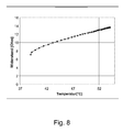
- PTC thermistors are electrically conductive materials whose resistance increases with temperature and thus conduct electricity better at low temperatures than at high temperatures.
- thermo resistor elements offers the practical advantage that at Applying a constant voltage to such a heating element, the overheating of the heating element is avoided, since with an increase in the operating temperature of the resistance of the heating element increases, whereby according to Ohm's law, the current decreases in proportion to the resistance increase, the total heating power achieved decreases and the heating element itself cool again.
- an intrinsic temperature limitation can be used instead of or in addition to an external regulation.
- the second polymer composition is not a PTC thermistor. This makes it possible to achieve a uniform stress distribution over the surface of the contacting layer, which results in a homogeneous temperature distribution in the planar element.
- the electrical resistance of the contacting layer is less than one tenth of the electrical resistance of the heating layer, preferably less than one hundredth or even less.
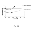
- the surface element may be formed such that the electrical resistance of the contacting layer in addition to the features of one or more of the aforementioned embodiments at an elongation of the contacting layer by more than 20%, in particular by more than 50% or even more than 100% , at most tripled, in particular not enlarged.
- the contacting layer contains an electrically conductive filler to a high mass fraction (that is to say in the case of a highly filled second polymer mass)
- the conductivity of the contacting layer may increase as it is stretched, so that the resistance as a whole decreases, given a suitable choice of material; appropriate materials and material combinations are known in the art.
- this configuration is ensures that even with a local elongation of the surface element no significant local increase in resistance occurs.
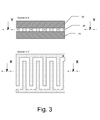
- the contacting layer has a branched comb structure or finger structure.
- a branched comb structure or finger structure Such a shape allows an optimal use of almost the entire surface of the surface element for heat generation with only small recesses, without thereby affecting the mechanical properties in any significant way or a strong voltage drop across the layer is expected.
- individual tines or fingers branch off from a main strand.
- the main strand may in this case have a larger cross section than the tines or fingers or the same cross section.
- a comb structure and a finger structure
- the branching elements are arranged at a comb structure on the same side of the main strand, while in a finger structure these branch off on different sides.
- Both structures can have both simple and multiple branches and thereby both regular and irregular arrangements and can be used as a plurality of electrodes both in an embodiment of the contacting layer as a single electrode and in an embodiment of the contacting layer.
- the first polymer composition and / or the second polymer composition comprises at least one electrically conductive filler in addition to the features of one or more of the aforementioned embodiments.
- the electrically conductive filler is selected from the group comprising graphite, carbon nanoparticles and carbon black, in particular Leitruß. The advantage of such a composition is that these fillers have a particularly good bond with the polymer matrix, so that such Polymer composition has a high overall cohesion and therefore strong mechanical load is.
- networks for example carbon blacks, carbon nanotubes or other nanoparticulate systems.
- Such a forming network is less affected in its conductivity when stretched than is the case with electrically conductive fillers which are present in the polymer composition in isolated form.
- the surface element is formed carrier-free in addition to the aforementioned features, that is, therefore, has no permanent carrier.
- the sheet may also comprise a permanent backing having an elongation at break of more than 20%, in particular more than 50% or even more than 100%, at a strain rate of 300 mm / min, and also a tensile modulus of elasticity of less than 1,000 MPa or even at most 100 MPa.
- a permanent carrier with high elasticity a highly stable surface element is obtained, which is excellently suited to be glued on uneven surfaces as well as on surfaces that are bent in more than one spatial direction (multi-dimensionally curved).
- an adhesive bond comprising a bonding substrate and one of the aforementioned surface elements.
- the previously known bonding composites have the disadvantage that they can not be glued reliably reliably on multi-dimensionally curved surfaces since, as a result of the inherent rigidity of the self-adhesive surface elements bonded thereto on one side, they can come off the curved surface. This disadvantage is avoided by using the surface element according to the invention.
- the bonding composite is a composite of at least one double-sided self-adhesive surface element and a viewing pane or mirror pane as a bonding substrate, since in such systems, as a result of the high inherent weight of the bonding substrate, detachment of the bonding substrate from the mount and the potential thereof resulting destruction of the bonding substrate would be particularly problematic.
- the present invention proposes the use of the surface element described above for the bonding of adhesive substrates in the automotive industry, in particular for heating the aforementioned adhesive bond. If an adhesive bond of the previously known type is bonded to a bonding substrate having an irregularly shaped or multi-dimensionally curved surface and then heated intrinsically as intended, the polymer composition is heated and softening of the polymer mass is accompanied by a decrease in the cohesion of the polymer composition softened polymer compound may result, so that the bonding composite at least partially detached from the bonding substrate. This disadvantage is avoided by using the surface element according to the invention for heating the adhesive bond.
- the invention relates to a self-adhesive surface element.
- a surface element in the context of this application, in particular all conventional and suitable structures apply at least substantially planar expansion. These allow a surface bonding and can be configured differently, in particular flexible, as an adhesive film, adhesive tape, adhesive label or as Formstanzling.
- At least substantially planar expansion means that the subregions of which the surface element is composed are present in a planar arrangement, wherein individual subregions can also protrude from this planar arrangement.
- This surface element is also a self-adhesive surface element. This means that at least one of the side surfaces of the surface element arranged parallel to its main extent or even both side surfaces is or are provided with self-adhesive properties and thus at least partially has or have a self-adhesive mass.
- self-adhesive compositions are understood to mean, without exception, all adhesives based on pressure-sensitive adhesives and / or hotmelt adhesives, ie adhesives which, on their own, permit permanent bonding to the substrate (the substrate, primer or adhesive foundation).
- "On the basis of” or “based on” means in this case that the adhesive properties of this adhesive system are at least greatly determined by the basic properties of this adhesive or of these adhesive constituents (the so-called base polymer), and in particular describes adhesive systems, their polymeric phase this adhesive or these adhesive composition components has a content of at least 40 wt .-%.
- the basic properties of the adhesive or adhesive composition components are additionally influenced by the use of modifying auxiliaries or additives or of other polymeric adhesives in the adhesive system.
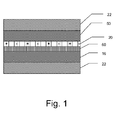
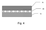
- the surface element contains at least two different layers, a heating layer and a contacting layer.
- a layer is in particular a planar arrangement of a system of uniform functionality, the dimensions of which are significantly smaller in one spatial direction than in the other two spatial directions which define the main extent.
- Such a layer may be formed compact or perforated and consist of a single material or of different materials, the latter may be the case in particular if they contribute to the uniform functionality of this layer.
- a layer may have a constant thickness over its entire areal extent or different thicknesses.
- a layer may also have more than one functionality.
- a layer sequence is in particular a spatial arrangement of individual layers which are perpendicular to their main extension one above the other (stacked) are arranged and each directly in contact with each other, without intervening layers are present.
- a contacting layer is arranged directly on a heating layer.
- each layer is designated, which is set up to heat the surface element.
- the contacting layer is any layer which conducts the electrical current well, with the aid of which a voltage can be applied to the heating layer and / or a current can be conducted through at least a portion of the heating layer; the contacting layer thus serves to connect external electrical supply lines to the surface element (contacting electrode function).
- the heating layer is in contact with one of the two side surfaces of the contacting layer (ie the upper side or the lower side of the contacting layer) so that these two layers are in direct contact, that is to say directly.
- the heating layer is electrically conductively connected to this one side surface of the contacting layer.
- a connection is referred to as being electrically conductive, in particular, if the total electrical resistance of the connection, which is composed of the resistances of the sections to be connected and the contact resistance of the connection, is at most three orders of magnitude greater than the total resistance of the remaining conductive areas and contacts.
- the contacting layer is an electrically conductive connection between the heating layer and the current source or voltage source (which usually provides a voltage of up to 50 V, the operating voltage in special applications also being able to be selected higher).
- the contacting layer can be formed either as one of the two electrode terminals (poles) of the heating layer or else form both electrode terminals. If the contacting layer represents only one of the two electrode terminals of the heating layer, then a second electrode connection is required so that a current can flow through the heating layer and the heating layer heats up.
- This second electrode connection can be formed within the surface element according to the invention - for example in the form of an additional second flexible contacting layer - or be provided on one of the two bonding substrates, for example as a metallic layer on the surface of a glass (such as a silver layer of a mirror).
- a Current flow through the heating layer then occur mainly in a direction perpendicular to the main extent.
- the contacting layer represents both electrode terminals of the heating layer, then the contacting layer contains at least two regions which are not connected to one another and which are formed as the two electrode leads (poles) of the heating layer. In this arrangement, in addition to the vertical current flow or instead, a lateral current flow within the main extent may occur.
- the contacting layer may typically have a thickness of less than 100 ⁇ m, preferably less than 20 ⁇ m and particularly preferably less than 10 ⁇ m.
- the heating layer consists of an intrinsically heatable first polymer composition and the contacting layer of an electrically conductive second polymer composition.
- a polymer composition is meant any composition containing at least one base polymer.
- a polymer composition may optionally also contain other ingredients, such as other polymers or additives.
- the heating layer as well as the contacting layer can in each case be present in any suitable arrangements, for example as a full-surface continuous layer or as a specially shaped structure, for example as a comb or finger structure.
- the base polymer of a polymer composition is referred to a polymer whose properties dominate single or even all properties of the entire polymer composition, it being understood that the properties of the polymer composition are additionally influenced by using modifying auxiliaries or additives or other polymers in the composition become.
- this may mean that the proportion of the base polymer in the total mass of the polymeric phase of the polymer composition (and thus optionally also the polymeric phase of the adhesive) more than 50 wt .-% and / or that the proportion of the base polymer to the total mass of the polymer composition more is 20% by weight. If the polymer composition contains only a single polymer, then this polymer is of course the base polymer.
- An intrinsically heatable polymer composition is any polymer composition which is heatable per se, that is to say that this polymer composition without further components or components is able to heat itself by passing an electrical current through the polymer composition or by applying an electrical voltage to the polymer composition It is irrelevant whether the current or the voltage is an alternating current or an alternating voltage or a direct current or a direct voltage.
- the process used for heat generation is usually a repeatable process, such as electrical resistance heating of the polymer mass.
- heat generation according to the invention can also be realized differently, for example as a one-off process, for example an exothermic irreversible chemical reaction which is electrically initiated.
- the surface element is deformable as a whole. This is achieved in that the surface element has special deformable layers.
- the deformability of the heating layer and the contacting layer results from the use of certain polymer compositions which form the heating layer or the contacting layer.
- Elastomers are elastically deformable and dimensionally stable polymers having a glass transition temperature below room temperature.
- a body made of an elastomer elastically deforms under an applied deformation force, but returns to its original undeformed shape when the deformation force ceases. This includes in the sense of the application also viscoelastic polymers that have a behavior that is partly elastic and sometimes viscous, so that the body after the loss of deformation only partially (incompletely) returns to its original shape and the remaining deformation energy then within a viscous flow process is degraded.
- a plastic polymer refers to polymers which deform plastically under the action of a deformation force, the deformation remaining completely or at least partially even after the deformation force ceases to exist.
- the polymer compositions must each have an elongation at break of more than 20%, in particular more than 50% or even more than 100%, at a strain rate of 300 mm / min, and also a tensile elastic modulus of less than 1000 MPa or even of not more than 100 MPa.
- the elongation at break is a measure of the mechanical strength and deformability of materials. This material characteristic value indicates the permanent percentage change in length of a specimen (relative to its initial length) that it has at break due to mechanical overloading.
- the tensile elastic modulus (modulus of elasticity, tensile modulus, coefficient of elasticity, Young's modulus) is a material characteristic value by means of which the relationship between stress and strain is described during the deformation of a material with linear elastic behavior.
- the tensile modulus of elasticity in the present case is understood to mean the initial tensile elastic modulus at the onset of the tensile load.
- the amount of elastic modulus is greater, the more resistance a material opposes to its deformation.
- the stiffness of a concrete body made of this material also depends on the processing and on the geometry of the body.
- Elongation at break and tensile modulus of elasticity are determined according to DIN EN ISO 527-3 at room temperature with a defined test specimen (type 5) for a strain rate of 300 mm / min.
- neither the heating layer nor the contacting layer must have continuous metallic structures (such as lead wires, electrodes, or heating wires), since the layers would be too limited in their stretchability due to the inherent rigidity of these structures so that the required ductility would not exist.
- this may have an electrical resistance, on the one hand high enough to heat on the other hand, low enough to establish a flow of current through the layer at all.
- the first polymer composition and as the second polymer composition it is possible to use in principle all polymer compositions which have a sufficient electrical conductivity and conduct an electric current flowing through this polymer composition essentially without decomposition and which, moreover, have the characteristics required according to the invention, in particular with regard to their properties Elongation at break and on their tensile elastic modulus.
- Polymer compositions having a corresponding elongation at break and a corresponding tensile elastic modulus are well known to the person skilled in the art; These can be adjusted with regard to the further required properties - such as the electrical conductivity - by measures that are also well known to those skilled in the art.
- the polymer compositions which are particularly suitable are, for example, polymer compositions whose base polymers include fluoropolymers, chloropolymers, silicones, polyamides, polyolefins and their copolymers, polyarylenes, polyacrylonitriles, ethylene-propene-diene monomer rubbers (EPDM ), Nitrile rubbers and mixtures or copolymers thereof.
- base polymers include fluoropolymers, chloropolymers, silicones, polyamides, polyolefins and their copolymers, polyarylenes, polyacrylonitriles, ethylene-propene-diene monomer rubbers (EPDM ), Nitrile rubbers and mixtures or copolymers thereof.
- EPDM ethylene-propene-diene monomer rubbers
- Nitrile rubbers Nitrile rubbers and mixtures or copolymers thereof.
- elastomers based on the polymer types mentioned, but also waxes can be used. It is possible to
- the first polymer composition and the second polymer composition may comprise at least one adhesive, so that the polymer compositions are adhesive polymer compositions (adhesives).
- adhesive polymer compositions adhesive polymer compositions
- self-adhesive compositions ie pressure-sensitive adhesives and hot melt adhesives.
- Adhesive adhesives are understood as meaning those adhesives which, even at relatively low pressure, permit permanent bonding to the substrate at room temperature.
- hot-melt adhesives are understood as meaning those adhesives which undergo permanent bonding to the substrate only at elevated temperatures, the bond thus obtained also in the case of a subsequent cooling of the bond is still maintained at room temperature.
- the bondability of pressure-sensitive adhesives as well as hot-melt adhesives is based on their adhesive properties.
- Adhesion is usually referred to as the physical effect which brings about the cohesion of two phases brought into contact at their interface on the basis of intermolecular interactions occurring there.
- the adhesion thus determines the adhesion of the adhesive to the substrate surface and can be determined as initial tack (the so-called tack) and as bond strength.
- plasticizers and / or adhesion-increasing resins are frequently added to the adhesive.
- Cohesion is usually the physical effect that results in the internal cohesion of a substance or mixture due to intermolecular and / or intramolecular interactions.
- the cohesive forces thus determine the viscosity and flowability of the adhesive, which can be determined as viscosity and shearing life, for example.
- these are often subjected to additional crosslinking, for which reactive (and thus crosslinkable) components or other chemical crosslinkers are added to the adhesive and / or the adhesive is exposed to actinic (high-energy) radiation in a post-treatment.
- the adhesive properties of a PSA are determined primarily by the ratio of adhesive and cohesive properties. For example, it is important for some applications that the adhesives used are highly cohesive, ie have a particularly strong internal cohesion, while for other applications a particularly high adhesion is required.
- either one of the two polymer compositions or both polymer compositions can be pressure-sensitive adhesives.
- one of the two polymer compositions or else both polymer compositions can be hot-melt adhesives.
- one of the two adhesives is a PSA and the other is a hot-melt adhesive, so that either the first polymer composition is a PSA and the second polymer composition a Hot-melt adhesive or that the first polymer composition is a hot-melt adhesive and the second polymer composition is a pressure-sensitive adhesive.
- PSAs are basically all PSA systems with suitable pressure-sensitive adhesive properties in question, so adhesive systems.
- the monomers used for the preparation of the PSAs are chosen in particular to such an extent that the resulting polymers can be used at room temperature or higher temperatures as PSAs.
- pressure-sensitive adhesive is an adhesive if it is appropriately " Handbook of Pressure Sensitive Adhesive Technology "by Donatas Satas (van Nostrand, New York 1989 ) has pressure-sensitive adhesive properties.
- n the number of runs via the monomers used
- W n the mass fraction of the respective monomer n in% by weight and T G, n the respective glass transition temperature of the homopolymer from the respective monomers n in K.
- pressure-sensitive adhesives for the first polymer composition and / or the second polymer composition it is therefore possible to use, for example, pressure-sensitive adhesives based on acrylates and / or methacrylates, natural rubbers and / or synthetic rubbers.
- PSAs based on acrylic acid and / or methacrylic acid and / or based on esters of the abovementioned compounds or those based on hydrogenated natural or synthetic rubbers since these are particularly suitable are resistant to aging and thus able to withstand repeated heating processes of the surface element according to the invention for a long time.
- Acrylate PSAs which are obtainable, for example, by free-radical polymerization and which are based at least in part on at least one acrylic monomer of the general formula CH 2 CC (R 1 ) (COOR 2 ), where R 1 is H or a CH 3 radical, are particularly suitable and R 2 is H or is selected from the group of saturated, unbranched or branched, substituted or unsubstituted C 1 to C 30 alkyl radicals.
- the at least one acrylic monomer should have a mass fraction of at least 50% by weight in the polymeric phase of the PSA.
- the at least one acrylic monomer (a1) has a mass fraction of 65 wt .-% to 100 wt .-% and the at least one comonomer (a2) has a mass fraction of 0 wt .-% to 35 wt.% In the polymeric phase of Self-adhesive on.
- an average molecular weight M w (weight average) of the self-adhesive composition of not more than 800,000 g / mol has proven to be advantageous, in particular with regard to the desired mechanical properties of the PSA.
- the at least one self-adhesive may also comprise or be based on natural or synthetic rubber compositions.
- the natural rubber is ground to an arbitrary molecular weight and additivized with the adhesive force increasing fillers (for example, adhesive resins) and with electrically conductive fillers.
- semicrystalline polymers such as EVA (ethylene-vinyl acetate) can also be used as a self-adhesive or added thereto.
- methyl acrylate methyl methacrylate, ethyl acrylate, n-butyl acrylate, n-butyl methacrylate, n-pentyl acrylate, n-hexyl acrylate, n-heptyl acrylate, n-octyl acrylate, n-octyl methacrylate, n-nonyl acrylate , Lauryl acrylate, stearyl acrylate, behenyl acrylate and branched isomers thereof, for example, isobutyl acrylate, 2-ethylhexyl acrylate, 2-ethylhexyl methacrylate, isooctyl acrylate or isooctyl methacrylate.
- cycloalkyl radicals may also be substituted, for example by C 1 - to C 6 -alkyl groups, halogen atoms or cyano groups.
- Specific examples are cyclohexyl methacrylate, isobornyl acrylate, isobornyl methacrylate and 3,5-dimethyl adamantyl acrylate.
- acrylic monomers and / or comonomers are used which have one or more substituents, in particular polar substituents, for example carboxyl, sulfonic acid, phosphonic acid, hydroxyl, lactam, lactone, N-substituted amide, N, substituted amine, carbamate, epoxy, thiol, alkoxy, cyano, halide and ether groups.
- substituents for example carboxyl, sulfonic acid, phosphonic acid, hydroxyl, lactam, lactone, N-substituted amide, N, substituted amine, carbamate, epoxy, thiol, alkoxy, cyano, halide and ether groups.
- moderately basic comonomers (a2) such as single or double N-alkyl-substituted amides, in particular acrylamides.
- moderately basic comonomers (a2) such as single or double N-alkyl-substituted amides, in particular acrylamides.
- comonomers (a2) are hydroxyethyl acrylate, hydroxyethyl methacrylate, hydroxypropyl acrylate, hydroxypropyl methacrylate, allyl alcohol, maleic anhydride, itaconic anhydride, itaconic acid, glyceridyl methacrylate, phenoxyethyl acrylate, phenoxyethyl methacrylate, 2-butoxyethyl acrylate, 2-butoxyethyl methacrylate, cyanoethyl acrylate, cyanoethyl methacrylate, glyceryl methacrylate, 6-hydroxyhexyl methacrylate, vinyl acetic acid , Tetrahydrofurfuryl acrylate, beta-acryloyloxypropionic acid, trichloroacrylic acid, fumaric acid, crotonic acid, aconitic acid, dimethylacrylic acid, although this list is not exhaustive.
- comonomers (a2) used are vinyl compounds, in particular vinyl esters, vinyl ethers, vinyl halides, vinylidene halides, vinyl compounds having aromatic rings and heterocycles in the alpha position, non-limiting examples being vinyl acetate, vinylformamide, vinylpyridine, ethylvinylether, vinyl chloride, vinylidene chloride, Styrene and acrylonitrile may be mentioned.
- the at least one comonomer (a2) may be a photoinitiator having a copolymerizable double bond, in particular selected from the group consisting of Norrish I photoinitiators or Norrish II photoinitiators, benzoin acrylates or acrylated benzophenones.
- additional monomers are added to the described comonomers (a2) which have a high static glass transition temperature.
- additional monomers are aromatic vinyl compounds such as styrene are suitable, wherein preferably the aromatic nuclei consist of C 4 - to C 18 blocks and may also contain heteroatoms.
- Particularly preferred examples are 4-vinylpyridine, N-vinylphthalimide, methylstyrene, 3,4-dimethoxystyrene, 4-vinylbenzoic acid, benzylacrylate, benzylmethacrylate, phenylacrylate, phenylmethacrylate, t-butylphenylacrylate, t-butylphenylmethacrylate, 4-biphenylacrylate and 4-biphenylmethacrylate, 2- Naphthyl acrylate and 2-naphthyl methacrylate and mixtures of these monomers, although this list is not exhaustive.
- the surface element according to the invention for the first polymer composition and / or the second polymer composition may contain hot-melt adhesives.
- hotmelt adhesives are in principle all hot melt adhesive systems with suitable hot melt adhesive properties in question, so H coordinatorschmelzklebrige systems.
- Hot-melt adhesive in the sense of the present invention is a surface element according to the invention if, after the melt-applied application to the primer and subsequent cooling, the bond strength at room temperature according to ASTM D 3330-04 (at a withdrawal speed of 300 mm / min on the adherend to be bonded) is greater than 1 N / cm, in particular greater than 3 N / cm or even greater than 5 N / cm.
- Hot-melt adhesives which can be used are all customary and suitable hotmelt adhesives, for example those based on polyolefins and copolymers of polyolefins and their acid-modified derivatives, ionomers, polyamides and their copolymers, and also block copolymers such as styrene block copolymers.
- a polymer composition in particular a self-adhesive composition, may of course comprise further formulation constituents and / or additives, such as, for example Auxiliaries, pigments, rheological additives, adhesion improving additives, plasticizers, resins, elastomers, anti-aging agents (antioxidants), light stabilizers, UV absorbers and other auxiliaries and additives, for example drying agents (for example molecular sieve zeolites or calcium oxide), Flow and leveling agents, wetting agents such as surfactants or catalysts and heat-conductive fillers, heat-storing fillers or additives which are released by heat or whose release is assisted by heat.
- auxiliaries for example Auxiliaries, pigments, rheological additives, adhesion improving additives, plasticizers, resins, elastomers, anti-aging agents (antioxidants), light stabilizers, UV absorbers and other auxiliaries and additives, for example drying agents (for example molecular sieve zeolites or calcium oxide),
- auxiliaries all finely ground solid additives such as chalk, magnesium carbonate, zinc carbonate, kaolin, barium sulfate, titanium dioxide or calcium oxide can be used. Further examples are talc, mica, silicic acid, silicates or zinc oxide. Of course, mixtures of the substances mentioned can be used.
- the pigments used may be organic or inorganic in nature. There are all types of organic or inorganic color pigments in question, for example, white pigments such as titanium dioxide for improving the light and UV stability or metal pigments.
- rheological additives examples include fumed silicas, phyllosilicates (for example bentonites), high molecular weight polyamide powders or powders based on castor oil derivatives.
- Additives for improving the adhesion may be, for example, substances from the groups of polyamides, epoxides or silanes.
- plasticizers for improving the bondability are phthalic acid esters, trimellitic acid esters, phosphoric acid esters, adipic esters and esters of other acyclic dicarboxylic acids, fatty acid esters, hydroxycarboxylic esters, alkylsulfonic acid esters of phenol, aliphatic, cycloaliphatic and aromatic mineral oils, hydrocarbons, liquid or semi-solid rubbers (for example nitrile rubbers or polyisoprene rubbers), liquid or semi-solid polymers of butene and / or isobutene, acrylic esters, polyvinyl ethers, liquid and soft resins based on the raw materials, which also form the basis for tackifying resins, wool wax and other waxes, silicones and polymer plasticizers such as polyesters or polyurethanes.
- plasticizers for improving the bondability are phthalic acid esters, trimellitic acid esters, phosphoric acid esters, adipic esters and esters of
- Aggregates that are released by heat or whose release is assisted by heat are those systems that contain an active substance that is released or activated as a result of the action of heat, so that a controlled release of this active substance is possible.
- the active substance here is any substance in question, which develops a special effect in the thermal release or activation, for example, a dye, a medical or cosmetic active ingredient or a detonator (initial explosive).
- the effect may occur, for example, as a result of the release of the substance (for example with a topically applicable active substance) or during thermal activation, for example a thermally initiated chemical reaction (for example a molecular rearrangement, a crosslinking reaction or a decomposition) or a thermally initiated physical process (for example, adsorption / desorption or a phase transition).
- the heat-releasable additive may be a topically applicable medicinal agent encapsulated in a fusible matrix.
- tackifying resins are all without exception all known and described in the literature adhesive resins used. Mention may be made representative of the pinene resins, indene resins and rosins, their disproportionated, hydrogenated, polymerized, esterified derivatives and salts, the aliphatic and aromatic hydrocarbon resins, terpene resins and terpene phenolic resins and C 5 - to C 9 - and other hydrocarbon resins. Any combination of these and other resins can be used to tailor the properties of the resulting adhesive as desired.
- all compatible with the corresponding base polymer (soluble) resins can be used, in particular reference is made to all aliphatic, aromatic, alkylaromatic hydrocarbon resins, hydrocarbon resins based on pure monomers, hydrogenated hydrocarbon resins, functional hydrocarbon resins and natural resins. In a preferred design resins are used which do not reduce the electrical conductivity and the heatability, even over a longer period of time.
- a further advantageous embodiment of the surface element can be achieved by adding a heat-storing filler to at least one of the layers.
- a heat-storing filler to at least one of the layers.
- Fillers with high heat capacity are, for example, aluminum, beryllium, boron, calcium, iron, graphite, potassium, copper, magnesium, phosphorus or compounds of the abovementioned substances, in particular aluminum oxide and aluminum chloride, calcium carbonate, calcium chloride, copper sulfate, magnetite , Hematite, magnesium carbonate and magnesium chloride, phosphorus chloride or phosphorus oxide (these substances can also fulfill other functions within the surface element, such as potassium or phosphorus in detonators).
- At least one of the polymer compositions has a high thermal conductivity, in particular of at least 0.5 W / m ⁇ K, very particularly preferably of more than 1 W / m ⁇ K.
- This can be achieved, for example, by adding heat-conductive fillers, in particular electrically insulating but highly heat-conductive fillers such as boron nitride or aluminum oxide, since the latter does not affect the electrical properties.
- electrically conductive fillers with high thermal conductivity can also be used, for example silver, aluminum or copper.
- composition of the first polymer composition may be the same or different from the composition of the second polymer composition.
- the first polymer mass and the second polymer mass must have a sufficiently low resistance and conduct electrical current at least substantially without decomposition.
- the polymer compositions may contain intrinsically conductive polymers (as a base polymer or as an additional formulation ingredient). It is particularly favorable, however, if the polymer compositions contain electrically conductive fillers.
- An electrically conductive (electrically conductive) filler is an admixture to a polymer composition which conducts electrical current either alone (ie without polymer compound) or only in the mixture with the polymer composition.
- electrically conductive fillers which are compatible with the respective polymer composition can be used as electrically conductive fillers.
- fillers are used which are selected from the group comprising graphite and carbon black, in particular Leitruß (for example, Printex® XE Fa. Degussa), and any combinations thereof.
- carbon-based fillers may also be used, in particular those which are nanoscale, ie have an extension of not more than 500 nm, preferably less than 200 nm or even less than 50 nm, in at least one spatial dimension
- carbon nanoparticles such as carbon nanotubes (for example, carbon nanotubes from Ahwahnee or carbon nanotube masterbatches from Hyperion Catalysis), carbon nanofibres, fullerenes and the like.
- the filler is used in such an amount that the proportion of the filler in the respective polymer mass is large enough to ensure a sufficiently high or low resistance of the polymer composition, but low enough, the mechanical properties of the first polymer composition only slightly to impair.
- the fillers can be used surface-modified. This can be targeted to individual properties of the first Polymer Mass, for example, to improve the dispersibility of carbon nanotubes or carbon black in the polymer composition.
- the conductivity of the polymer masses depends inter alia on the degree of filling of the electrically conductive filler, that is to say its mass fraction in the polymer composition. This has both effects on the conductivity of the second polymer composition as well as on the achievable temperature and heating rate of the heating layer. By increasing the degree of filling, higher conductivities and possibly even higher temperatures can be achieved.
- the electrical conductivity of a polymer composition is also dependent on its base polymer. For example, the expression of the effect of the electrical heatability of the first polymer composition can be determined by the degree of filling.
- the degree of filling here is advantageously between 1 and 60 wt .-%. Very preferably between 5 and 30% by weight of filler are used.
- the electrically conductive fillers may be admixed with the monomers of the polymer composition prior to the polymerization and / or during the polymerization and / or mixed with the polymers only after the polymerization has ended.
- the electroconductive filler after polymerization is added to a melt of a base polymer of the polymer composition.
- the first polymer composition forms the heating layer and the second polymer composition forms the contacting layer.
- the heating layer is cold conductive, so that it has a positive temperature coefficient and thus shows a PTC effect.
- the contacting layer is preferably not cold-conducting.
- a cold conductive behavior results from the choice of a suitable first polymer composition.
- the first polymer mass can be designed so that the heat generation in the heating layer is limited by the PTC effect for the respective operating voltage and the respective operating current, so that the layer behaves self-regulating with respect to heat generation, and in particular does not exceed a specified maximum temperature. Overheating of the surface element can thus be avoided.
- EP 0 512 703 A1 such as EP 0 852 801 A1 described in detail.
- these PTC thermistors are applied in the form of an ink on a continuous conductor surface which serves as an electrical contacting electrode and which is arranged on a separate carrier film of a thickness of usually 75 .mu.m to 250 .mu.m.
- the solvent contained in the ink is removed in a final drying step.
- Such inks are in EP 0 435 923 A1 described in detail.
- the heating layer it is of course possible to use in the first polymer composition, in principle, all polymers having suitable mechanical properties which have a PTC effect, ie behave in a cold-conducting manner.
- the occurrence and the extent of a PTC effect depend on a network formation, for example on whether or not the electrically conductive filler itself is agglomerated.
- the PTC effect can be assisted, inter alia, by orientations within the polymer constituents of the first polymer composition introduced during the production process, for example by deliberately introducing an anisotropy with respect to physical properties and / or with respect to the alignment of the macromolecules.
- a polymer composition with an electrically conductive filler is used as a cold-conducting system, then it has proven advantageous to use multiphase systems, in particular those in which at least one phase in the temperature range in which the PTC effect occurs as a result of heating Volume expansion undergoes, which is at least partially responsible for the cold-conducting behavior according to generally accepted scientific explanation (see J. Meyer in Polymer Engineering and Science, 13 (1973), pp. 462-468 ).
- polymer compositions based on polymers or polymer blends are also considered, which have one or more further fillers in addition to the electrically conductive filler.
- the use of polymer compositions which have partially crystalline polymers has proven particularly advantageous.
- Semi-crystalline polymer systems which can be used are both single-phase and multiphase systems, both homopolymers and copolymers, in particular semicrystalline block copolymers.
- the semicrystalline polymers may be part of the base polymer itself or may be an additive.
- the crystalline subregions of such partially crystalline polymers exhibit a greater thermal expansion when softening the polymer matrix than their amorphous regions.
- the first polymer composition in the heating layer contains at least 30% by weight of semicrystalline polymers, even better is a proportion of partially crystalline polymers of at least 50% by weight in the first polymer composition. It has been found that the suitability for achieving the PTC effect with the fraction of semicrystalline polymers increases surprisingly strongly, especially in the case of non-adhesive polymer compositions and hot-melt adhesives as the first polymer composition. On the other hand, pressure-sensitive adhesives lose their pressure-sensitively adhesive properties as the partially crystalline portion increases, so that the proportion of partially crystalline polymers is lower when pressure-sensitive adhesives are used than with hot-melt adhesives in order to ensure sufficiently high pressure-sensitive adhesiveness.
- non-adhesive polymer compositions and hot melt adhesives are well suited for exploiting the PTC effect beyond expectations.
- Polymeric compositions of partially crystalline polymers which are contained in the base polymer of the polymer composition at 100% by weight or which are contained in the base polymer of the polymer composition at least to almost 100% by weight have proven particularly advantageous as the first polymer composition.
- a polymer composition as the first polymer composition in particular those semi-crystalline polymers are advantageous in which the degree of crystallinity is more than 20% or even more than 40%.
- the degree of crystallinity can be determined by Differential Scanning Calorimetry (DSC).
- polyolefins for example low-density polyethylene
- copolymers of polyolefins for example ethylene-vinyl acetate (EVA), ethylene-acrylic acid (EAA), ethylene-methacrylic acid (EMAA), ethylene-ethyl acrylate or ethylene
- EVA ethylene-vinyl acetate
- EAA ethylene-acrylic acid
- EEMA ethylene-methacrylic acid
- ethylene-ethyl acrylate or ethylene ethylene-ethyl acrylate
- they also have particularly advantageous hot-melt adhesive properties, so that they can be used as a base polymer in the case of a first polymer composition based on a hot-melt adhesive.
- thermoplastics are acid-modified (for example maleic or maleic anhydride-modified) polyolefins or their copolymers, since they are particularly well compatible with the electrically conductive fillers such as carbon black or carbon nanotubes and when using these polymers are particularly simple homogeneous dispersions of the filler in the polymer matrix.
- acid-modified for example maleic or maleic anhydride-modified
- polyolefins or their copolymers since they are particularly well compatible with the electrically conductive fillers such as carbon black or carbon nanotubes and when using these polymers are particularly simple homogeneous dispersions of the filler in the polymer matrix.
- Very particularly preferred block copolymers are styrene block copolymers such as SBS (styrene-butadiene-styrene block copolymers), SIS (styrene-isoprene-styrene block copolymers), SEBS (styrene-ethylene-butylene-styrene block copolymers) or SEPS (styrene-styrene block copolymers). Ethylene-propylene-styrene block copolymers).
- SBS styrene-butadiene-styrene block copolymers
- SIS styrene-isoprene-styrene block copolymers
- SEBS styrene-ethylene-butylene-styrene block copolymers
- SEPS styrene-styrene block copolymers
- polymeric or inorganic fillers that support the PTC effect during their heating with their melting.
- These may be, for example, highly crystalline polyolefin waxes or ionic liquids (low-melting metal salts).
- a combination of different types of electrically conductive fillers may also be advantageous, since in this way sufficient cold-conduction properties can be achieved with the lowest possible degree of filling, in particular in the combination of carbon nanotubes with carbon black or graphite.
- the surface of the electrically conductive fillers such as the soot particles, completely or partially covered with metals such as nickel, silver or gold, with silanes or with formamides.
- the mixing of the polymer phase of a polymer composition with the electrically conductive filler can be carried out with all customary mixing methods. If the polymer composition is applied from the melt, for example, to the surface element according to the invention, the electrically conductive filler can preferably be introduced directly into the melt. In this case, a homogeneous incorporation in the inventive sense is desirable. Homogeneous distributions of the filler in the polymer composition are also preferably achieved by compounding in twin-screw extruders, continuous kneaders (for example Buss kneaders) or planetary roller extruders. An advantage of this process is a short-term contamination of the manufacturing process with the separate filler and the avoidance of solvents.
- the polymer compositions used for the surface elements according to the invention are preferably additionally crosslinked.
- high crosslinking levels are often sought for the first polymer composition which enhance the PTC effect (cf. EP 0 311 142 A1 such as US 4,775,778 A ) and are therefore particularly suitable.
- Crosslinking also eliminates or reduces the effects of any negative temperature coefficient (NTC) effect sometimes observed at temperatures above the melting point of a polymer mass.
- NTC negative temperature coefficient
- a base polymer of the first polymer composition may preferably have a degree of crosslinking which corresponds to at least a gel value of 35%, in particular a gel value of more than 60%.
- the gel value is understood to mean the ratio of the proportions of a base polymer which are not soluble in a suitable solvent (for example toluene or xylene) to the sum of soluble fractions and insoluble fractions of the base polymer.
- a high degree of crosslinking can be obtained, for example, in a crosslinking step with electron beams.
- Typical irradiation devices which can be used are linear cathode systems, scanning systems or segmented cathode systems, provided they are Electron beam accelerator acts. A detailed description of the state of the art and the most important process parameters can be found at Skelhorne, "Electron Beam Processing, in Chemistry and Technology of UV and EB Formulation for Coatings, Inks and Paints", Vol. 1, 1991, SITA, London on.
- Typical acceleration voltages are in the range between 50 kV and 500 kV, preferably in the range between 80 kV and 300 kV.
- the applied waste cans range between 5 kGy to 150 kGy, in particular between 20 kGy and 100 kGy. Other methods can also be used which enable high-energy irradiation.
- the electrical conductivity of the first polymer mass and thus of the thermal heating via the degree of crosslinking can be effected.
- increasing the electron beam dose acting in a crosslinking reaction and concomitantly by increasing the degree of crosslinking
- the degree of crosslinking can be used to control the cold-conducting behavior of the first polymer composition.
- crosslinking agents and / or promoters for crosslinking in particular those which can be excited thermally or by means of electron beams, can additionally be mixed with the polymer compositions.
- thermally activatable crosslinkers bifunctional or multifunctional epoxides, hydroxides, isocyanates or silanes are preferably mixed.
- Suitable crosslinkers for electron beam crosslinking are, for example, bifunctional or multifunctional acrylates or methacrylates or triallyl cyanurates and triallyl isocyanurates.
- the surface element thus comprises at least one layer within which heat can be generated, as well as an electrically conductive layer which represents at least one electrode (one pole) of the contacting layer. It is important here that the heating layer and also the contacting layer are deformable.
- a surface element consists of only two layers, a heating layer of a self-adhesive and a contacting layer, the latter in this structurally simplest embodiment either non-adhesive (for a one-sided adhesive surface element) or may also be formed as a self-adhesive (for a double-sided adhesive surface element).
- the heating layer and the contacting layer consist of polymer compositions which differ only in terms of their content of electrically conductive fillers, but otherwise have an identical composition.
- the surface element according to the invention may have additional layers in addition to the heating layer and the contacting layer.
- the surface element contains one or more layers of adhesive compounds, such as that of the two side surfaces of the contacting layer, which is not in direct contact with the heating layer, itself not self-adhesive, but with an additional adhesive layer of a Self-adhesive is in contact.
- each layer is called, which contains an adhesive and adapted for adhesive bonding of the surface element with a primer.
- a self-adhesive composition may be provided instead of or in addition to the side surface of the heating layer, which faces away from the contacting layer.
- Suitable self-adhesives of this type are in principle all customary and suitable PSAs or hot-melt adhesives, in particular the self-adhesives described above for the first polymer composition and the second polymer composition, although these need not necessarily be electrically conductive.
- the surface element according to the invention may for example also comprise a structure of a heating layer and a contacting layer, both of which are not self-adhesive, and on the side surface (heating layer and / or contacting layer) an adhesive layer can be applied to achieve self-tackiness there.
- At least one layer of the heatable surface element is equipped with a mechanism which, when the surface element is first heated, leads to a cohesion increase in the first polymer mass, the second polymer mass and / or optionally in further self-adhesives.
- This can be achieved, for example, by increasing the crosslinking density by means of a thermally initiated postcrosslinking, which can be initiated in particular by the (intrinsic) heating of the planar element itself.
- a surface element is therefore used in such a way that first the bond is produced with at least one bonding substrate and then the initial heating is carried out, during which a solidification of the bond sets.
- the surface element is usually formed carrier-free, as a result, a maximum deformability of the surface element is guaranteed overall.
- a deformable permanent support may also be provided in the surface element.
- This permanent carrier can be used, for example, to improve the mechanical properties, such as the puncture resistance of the planar element as a whole.
- the permanent carrier can be closed over the entire surface or formed open.
- any suitable support materials can be used, such as films of elastic or thermoplastic plastics, polymer-textile surface elements (for example, fabrics, scrims, knitted fabrics, nonwovens) or combinations of such materials.
- the support In order to ensure the excellent deformability of the surface element to be achieved according to the invention, the support must have an elongation at break of more than 20%, in particular more than 50% or even more than 100%, and moreover at a strain rate of 300 mm / min have a tensile elastic modulus of less than 1,000 MPa or even at most 100 MPa.
- polymer-textile carrier systems have good or even excellent three-dimensional deformability in accordance with the respective textile bond (for example, knitted fabrics are considerably more elastic in comparison to fabrics). With better deformability, however, these systems are also considerably thicker, since here the extensibility is not produced by the fiber material itself, but is achieved only by the transverse contraction of the polymer textile composite, which takes place substantially in the thickness direction. Due to the large thickness and due to high transverse contraction only small dimensional stability of polymer-textile support materials film-like materials are usually preferred.
- the permanent support in addition to its high flexibility has a high thermal conductivity, in particular a thermal conductivity of at least 0.5 W / m ⁇ K or even more than 1 W / m ⁇ K.
- Particularly preferred materials are polymers filled with thermally conductive fillers such as boron nitride or aluminum oxide.
- Such permanent supports typically have a thickness of less than 50 microns, preferably less than 25 microns, so as not to affect the overall flexibility of the construction.
- the energy required to melt a hot-melt adhesive can be better introduced, which leads to shorter cycle times when the surface element according to the invention is applied to the bonding substrate.
- the permanent support is designed as a polymeric foam, whereby the deformability of the entire surface element is not significantly impaired.
- the permanent carrier may also be designed to be electrically insulating, for example in order to protect the user of the planar element from contact with current-carrying parts of the planar element.
- the surface element may have a temporary carrier on one of the self-adhesive side surfaces and / or possibly also on the other self-adhesive side surface.
- a temporary support any separating cover material may be used, such as a release paper or a process liner, which at least partially covers one of the outer self-adhesives.
- a masking material for example, all siliconized or fluorinated films are suitable with a release effect, which are removable without residue.
- film materials which may be mentioned here are PP (polypropylene), BOPP (biaxially oriented polypropylene), MOPP (monoaxially oriented polypropylene), PET (polyethylene terephthalate), PVC (polyvinyl chloride), PUR (polyurethane), PE (polyethylene), PE / EVA (polyethylene Ethylene-vinyl acetate copolymers) and EPDM (ethene-propylene-diene terpolymers).
- release papers can also be used, for example glassine papers, Kraft papers or polyolefinically coated papers.
- Coating materials which themselves have a high thermal conductivity, in particular a thermal conductivity of at least 0.5 W / m ⁇ K or even more than 1 W / m ⁇ K, can also be used with particular advantage.
- Particularly preferred materials are polymers filled with thermally conductive fillers such as boron nitride or aluminum oxide.
- thermally conductive cover materials can for melting a hot melt adhesive required energy can be better introduced, resulting in about shortened cycle times when applying the surface element according to the invention on the bonding substrate.
- the polymer compositions of the surface element according to the invention can be prepared by the conventional methods for producing polymeric surface elements according to the prior art. These include, for example, flat film extrusion, blown film extrusion, the calendering process, the coating from a solution, from a dispersion or from a monomeric or prepolymeric precursor of the polymer.
- the surface elements thus obtained typically have a total thickness of at most 1000 .mu.m, in particular from 10 .mu.m to 400 .mu.m or even from 30 .mu.m to 200 .mu.m.
- one of the two polymer compositions is usually first spread in layers, for example on a permanent support or on a production carrier - a so-called process liner - which is separated again from the surface element during the process or at the latest at the end of the process.
- the other polymer composition is applied to this polymer composition layer.
- a further self-adhesive may be applied to the exposed side surface of the contacting layer and / or the heating layer, to which the manufacturing carrier - if necessary - can be previously removed from the polymer composition.
- the surface element according to the invention in any other manufacturing process deviating therefrom, for example by applying one of the two polymer compositions to a support (production carrier or a permanent support) and the other of the two polymer compositions to another support, and the two polymer compositions are then joined together, for example in a lamination step.
- a further self-adhesive may then be applied to the permanent support or to one of the two polymer compositions, the latter only after removal of the temporary support.
- the second polymer composition of the contacting layer on the first polymer composition or optionally on a support
- all known methods such as the application (for example in a printing process such as screen printing) of electrically conductive inks (lead inks) and printing inks, conductive inks or conductive pastes, in which the polymer is in dispersion, solution or melt, the transfer of separately molded polymer layers or polymer films by means Hot stamping, heat sealing, laminating or laminating or the discontinuous application of mixtures of polymers and electrically conductive fillers (for example polymer-carbon black compounds), in which case the second polymer composition of the contacting layer should have a conductivity which is at least a factor of 10 higher as the conductivity of the intrinsically heatable first polymer composition.
- the surface element can also be produced with a three-dimensional shape, which is achieved via the thermoformability of the two layers.
- a three-dimensionally shaped sheet may offer advantages in adhering to a correspondingly shaped surface of a bonding substrate.
- the surface elements thus obtained are used according to the invention for connecting two bonding substrates together or for joining two different subregions of a single bonding substrate. If the surface element is self-adhesive on both sides, then it is adapted to adhesively bond the surfaces of two bonding substrates together.
- the surface element is used for the bonding of bonding substrates in the automotive industry and is used for example in automobiles, buses, railways, ships or aircraft.
- the surface element according to the invention can be present here as part of a bonding composite.
- An adhesive bond in the present case is any bond obtained by bonding a surface element and at least one bonding substrate, which is bonded either directly to a side surface of the surface element or via other components.
- a mirror pane is used as the bonding substrate, in particular the rear side of the mirrored side of a mirror pane, or - in the case of a transparent planar element - a viewing pane, for example a display window or a window pane Windshield.
- the surface element according to the invention is used for heating such a bonding composite.
- the surface element according to the invention for example as a mirror heating (exterior and interior mirrors), in a heatable interior trim (attachment, noise insulation, heating), for wiper water heating or freezing protection, for a tank heating (especially for diesel vehicles), for the heating of fuel pipes (at the same time as attachment ), in a heating system for defrosting systems (hydrofoil, possibly including fixing functions), in a steering wheel heater, for heating air heating (auxiliary heating when the engine is cold) or for intake air preheating (combustion air).
- a mirror heating exterior and interior mirrors
- a heatable interior trim attachment, noise insulation, heating
- for wiper water heating or freezing protection for a tank heating (especially for diesel vehicles), for the heating of fuel pipes (at the same time as attachment ), in a heating system for defrosting systems (hydrofoil, possibly including fixing functions), in a steering wheel heater, for heating air heating (auxiliary heating when the engine is cold) or for intake air preheating (combustion air).
- the surface element is fixed only under pressure on the bonding substrate (in the case of a PSA) or, when heat is applied under pressure, fixed to the bonding substrate (in the case of a hot-melt adhesive).
- the introduction of heat takes place from the outside; Alternatively, however, the heat required to achieve a stable bond can also be generated intrinsically in the heating layer.
- Fig. 1-6 show in general different structures of heated surface elements. Subsequently, concrete examples of the surface element according to the invention will be described by way of example and experiments for determining the properties of these surface elements will be presented. The results of these experimental measurements are in Fig. 7-12 played.
- a surface element known from the prior art with a first heating layer 50 and a contacting layer 20 is shown, wherein the contacting layer 20 is connected to a permanent carrier 16 via a laminating adhesive layer 60.
- the surface element is formed with two pressure-sensitive adhesive layers 22 adhesive on both sides.
- Such a surface element has a relatively complicated multilayer structure and is neither deformable nor flexible.
- FIG. 2 a an inventive two-sided bondable surface element of a contacting layer 20 and a heating layer 10 is shown.
- this surface element is shown in the one-sided bonded state as Verklebungsverbund with a mirror glass, which consists of a glass plate 40, which has a metallic mirror layer 21 on one side.
- the contacting layer 20 and the heating layer 10 are formed in the present case of electrically conductive polymer compositions which are highly elastic and thus deformable.
- the polymer composition of the heating layer 10 is also designed as a self-adhesive.
- the self-adhesive (that is to say adhesive-tacky or hot-melt-tacky) heating layer 10 is bonded to the rear side of the metallic mirror layer 21.
- the contacting layer 20 is here a continuous polymer mass layer, which represents the one electrode of the heating layer; the other electrode is formed by the metallic mirror layer 21.
- Fig. 3 an inventive two-sided adhesive surface element is shown with a contacting layer 20 and a heating layer 10, wherein the contacting layer 20 itself is formed non-adhesive and instead a additional self-adhesive layer 30 is attached to the contacting layer 20.
- the contacting layer 20 here has a comb structure of uniform cross-section, in which the fingers branch off in the upper part region on the same side of the main strand as the fingers in the lower part region.
- the contacting layer 20 has two non-interconnected portions, so that they can serve as the two contact electrodes (poles) of the heating layer (represented by the arbitrarily selected different symbols "+" and "-"). In combination with a bonding substrate, therefore, a further contact electrode is not required as an external counterelectrode.
- Fig. 4 an inventive one-sided bondable surface element with a contacting layer 20, a heating layer 10 and a deformable permanent support 16 is shown, wherein the contacting layer 20 and heating layer 10 are each formed either adhesive or hot melt adhesive.
- the contacting layer 20 has a two-part comb structure, so that no further contact electrode is required as an external counterelectrode in conjunction with a bonding substrate.
- the permanent carrier 16 has a thickness of less than 50 ⁇ m, preferably less than 25 ⁇ m.
- FIG. 5 an inventive double-sided adhesive surface element is shown with a contacting layer 20 and a heating layer 9/11, wherein the contacting layer 20 is not self-adhesive, but in addition a further self-adhesive layer 22/23 is attached to the contacting layer 20.
- the structure shown are the heating layer and the further self-adhesive layer different types of self-adhesive by the heating layer 9 is formed hot melt adhesive when the further self-adhesive layer 22 is pressure-sensitive, or by the heating layer 11 is pressure-sensitive, if the further self-adhesive layer 23 is formed H thoroughlyschmelzklebrig.
- FIG. 6 an inventive two-sided adhesive surface element is shown with a contacting layer 20 and a pressure sensitive adhesive layer 11, wherein the contacting layer 20 itself is non-adhesive and instead an additional self-adhesive layer 30 is attached to the contacting layer 20.
- this surface element has a temporary carrier 24, which is in contact with the heating layer 11.
- test D To determine the flexibility of the surface element (test D), the deflection of a one-sided clamped 10 cm long and 2 cm wide strip of a surface element was measured under its own weight in a horizontal position.
- Fig. 3 used schematically shown construction.
- an intrinsically heatable surface element comprising a self-adhesive layer 30, a contacting layer 20 and a heating layer 10 is shown, wherein the contacting layer 20 has a double comb structure.
- the test was carried out without covering materials on the pressure-sensitive adhesive surfaces. The strip was cut out in such a way that the strip conductors lay essentially transversely to the longitudinal direction of the strip. All measurements were carried out at room temperature under conditioned conditions.
- the tensile elastic modulus and the elongation at break were determined at room temperature in accordance with DIN EN ISO 527-3 with a test specimen of type 5 for a strain rate of 300 mm / min.
- the electrical resistance of the sample was measured by means of a laboratory multimeter at least substantially without current.
- the measuring electrodes were located within the narrow parallel part of the measuring body at a distance of 25 mm.
- the electrical resistance of the specimen was additionally recorded during the measurement of the tensile elastic modulus and the elongation at break.
- surface elements according to the invention surface elements having a pressure-sensitive adhesive or a hot-melt adhesive as the first polymer composition were produced.
- a base PSA analogous to the disclosure in US Pat EP 04 712 016 which had a comonomer composition of 44.5% by weight of 2-ethylhexyl acrylate, 44.5% by weight of n-butyl acrylate, 8% by weight of methyl acrylate and 3% by weight of acrylic acid.
- the determination of the molecular weight gave an average molecular weight M w of 650,000 g / mol at a polydispersity M w / M n of 7.0.
- the base PSA thus obtained was mixed in solution with 40% by weight of graphite (Timcal Timrex KS 6) and then applied by means of a brush to a siliconized glassine release paper (Laufenberg). After drying at 120 ° C. for 10 minutes, the thickness of the pressure-sensitive adhesive layer thus obtained was 100 ⁇ m.
- this pressure-sensitive adhesive was crosslinked by electron irradiation.
- the electron irradiation was carried out with a device of the company. Electron Crosslinking AB, Halmstad, Sweden.
- the coated pressure-sensitive adhesive tape was passed through a standard provided cooling roller under the Lenard window of the accelerator. In the process, the atmospheric oxygen in the irradiation zone was displaced by flushing with pure nitrogen. The web speed was 10 m / min.
- the electron beam dose here was 50 kGy at an acceleration voltage of 180 kV for Example 1.
- an ethylene-vinyl acetate copolymer (EVA) of the type Escorene Ultra FL 00728 (ExxonMobil) with 28% by weight vinyl acetate content was used as the base hotmelt adhesive.
- EVA ethylene-vinyl acetate copolymer
- Into this base hot-melt adhesive composition was compounded by means of a measuring mixer of the type Haake Rheomix at a temperature of 140 ° C and a speed of 120 min -1 28 wt .-% Leitruß (Ensaco 260 G, Timecal) over a period of 45 min. From the polymer compound thus obtained, a surface element having a thickness of 200 ⁇ m was produced by means of a vacuum press.
- an ethylene-vinyl acetate copolymer (EVA) of the type Escorene Ultra FL 00728 (ExxonMobil) with 28% by weight vinyl acetate content was used as the base hot-melt adhesive.
- EVA ethylene-vinyl acetate copolymer
- Into this base hot-melt adhesive composition was measured by means of a measuring mixer of the Haake Rheomix type at a temperature of 140 ° C. and a speed of 120 min -1 28% by weight.
- Leitruß Printex XE2, Degussa
- a surface element having a thickness of 200 ⁇ m was produced by means of a vacuum press. From the thus obtained film, a comb-shaped wiring pattern having an electrode pitch of 1.5 mm and an electrode width of 5.0 mm was cut out as a bonding layer.
- a first non-deformable polymer mass of the contacting layer was with a commercially available dispersion of an electrically conductive polymer composition based on PEDOT / PSS (Clevios F, Fa HC Starck) a comb-shaped conductor track structure with an electrode spacing of 1.5 mm and an electrode width of 5.0 mm in a thickness of 5 microns applied to a process liner.
- a commercially available silver conductive varnish (from Conrad Electronic) was applied in a layer thickness of 25 ⁇ m to an unfilled ethylene vinyl acetate film of 200 ⁇ m thickness.
- Example 1 the in Fig. 3 illustrated construction using the previously described intrinsically heatable pressure-sensitive adhesive having a thickness of 100 microns as the heating layer 10, the previously described base PSA, which under the same conditions as the intrinsically heatable PSA for further crosslinking electron beams was exposed, in a thickness of 75 .mu.m Self-adhesive composition layer 30 and used with the above-described deformable polymer composition layer having a double comb structure as the contacting layer 20.
- the heatable surface had a size of 180 cm 2 .
- Example 2 the in Fig. 3 shown structure using the previously described intrinsically heatable hot melt adhesive having a thickness of 200 microns as the heating layer 10, the above-described base PSA with a thickness of 75 .mu.m as Disklebemassetik 30 and the previously described deformable polymer mass layer with double comb structure used as contacting layer 20.
- the heatable surface had a size of 180 cm 2 .
- peel force was determined for the above-described base hot-melt adhesive as well as for the previously described heatable hot-melt adhesive according to Test B: Based hot melt adhesive: 4.5 N / cm Heatable hotmelt adhesive: 2.9 N / cm
- Example 1 53 ° C
- Example 2 54 ° C Comparative Example 1 54 ° C
- Fig. 7 shows the results for Example 1
- Fig. 8 the results for Example 2
- Fig. 9 the results for Comparative Example 1.
- Example 1 The deformability of the surface elements was determined for Example 1 (with the heatable PSA described above) and for Example 2 (with the heatable hotmelt adhesive described above) and for Comparative Example 1 according to Test D. The following deflections were measured: Example 1: 75 mm Example 2: 60 mm Comparative Example 1 15 mm
- the deformability of the surface elements was determined on the basis of the tensile elastic modulus and the elongation at break for the intrinsically heatable pressure-sensitive adhesive (base PSA), the intrinsically heatable hot melt adhesive (base hot-melt adhesive), the deformable polymer composition, the first non-deformable polymer composition (polymer composition based on PEDOT / PSS) and the second non-deformable polymer composition (silver conductive ink) determined according to test E.
- sample modulus of elasticity elongation at break intrinsically heatable pressure-sensitive adhesive 2.2 MPa 424% intrinsically heatable hot melt adhesive 35.6 MPa 306% deformable polymer composition 63 MPa 367% first non-deformable polymer mass not definable [ ⁇ 10%] second non-deformable polymer mass not definable [ ⁇ 25%]
- the second non-deformable polymer composition has an elongation at break within the range of more than 20% required in the present invention, it does Requirement of a tensile elastic modulus of less than 1,000 MPa is not met by this system.
- This result shows that it is not sufficient to achieve the effect according to the invention if the polymer compositions have only one of the two characteristics (elongation at break and tensile elastic modulus); Rather, it is imperative that both polymer compositions realize both features simultaneously.
- Fig. 10 shows the change in electrical resistance during elongation of the specimen for the two intrinsically heatable adhesives, from which according to the invention a heating layer can be formed.
- Fig. 11 is the change in the electrical resistance at an elongation of the test piece for the deformable polymer composition ("elastic electrode"), from which a contacting layer according to the invention can be formed, and for the second non-deformable polymer composition (silver conductive ink).
- the deformable polymer mass exhibits a small decrease in electrical resistance to an elongation of about 25%, whereas at higher strains an increase in electrical resistance is observed.
- the absolute value of the resistance is more than an order of magnitude lower than in FIG Fig. 10 shown data curves of the polymer compositions for the heating layer.
- the silver conductive ink shows a sudden increase in electrical resistance at an elongation of more than 25%, which was interpreted as cracking of the paint film.
- FIG. 12 are the in Fig. 10 and 11 shown measured data curves as related to the respective initial resistance data curves summarized, therefore, therefore, reflect the relative change in electrical resistance. It can be seen that with all the polymer compositions which can be used in the surface element according to the invention, in contrast to the silver conductive ink, even at strains of 100%, the resistance does not exceed twice the original initial value, so that all these polymer compositions allow a flow of current through the polymer composition (if appropriate with heating effect).
Landscapes
- Engineering & Computer Science (AREA)
- Multimedia (AREA)
- Mechanical Engineering (AREA)
- Laminated Bodies (AREA)
- Adhesives Or Adhesive Processes (AREA)
- Surface Heating Bodies (AREA)
- Resistance Heating (AREA)
- Adhesive Tapes (AREA)
- Lining Or Joining Of Plastics Or The Like (AREA)
Abstract
Description
Die Erfindung betrifft ein selbstklebendes Flächenelement umfassend eine Heizschicht und eine Kontaktierungsschicht, wobei die Heizschicht mit einer der beiden Seitenflächen der Kontaktierungsschicht in Kontakt steht und mit dieser elektrisch leitend verbunden ist. Die Heizschicht besteht aus einer intrinsisch erwärmbaren ersten Polymermasse, die als Leiter ausgebildet ist, der sich bei Hindurchleiten eines elektrischen Stroms erwärmt. Die Erfindung betrifft ferner einen Verklebungsverbund aus einem Verklebungssubstrat und dem zuvor beschriebenen Flächenelement sowie die Verwendung eines solchen Flächenelements zum Beheizen eines Verklebungsverbunds.The invention relates to a self-adhesive surface element comprising a heating layer and a contacting layer, wherein the heating layer is in contact with one of the two side surfaces of the contacting layer and is electrically conductively connected thereto. The heating layer consists of an intrinsically heatable first polymer mass which is formed as a conductor which heats up when passing an electric current. The invention further relates to a bonding composite of a bonding substrate and the surface element described above and the use of such a surface element for heating a bonding composite.
In vielen Bereichen werden zum Beheizen von Gegenständen oder Räumen Elektroheizungen eingesetzt. In Elektroheizungen wird Wärme als thermische Energie durch Umwandlung von elektrischer Energie (einschließlich magnetischer Energie) gewonnen. Elektroheizungen können grundsätzlich auf unterschiedlichen technischen Prinzipien beruhen.In many areas, electric heaters are used to heat objects or rooms. In electric heaters, heat is obtained as thermal energy by conversion of electrical energy (including magnetic energy). Electric heaters can basically be based on different technical principles.
Neben der Wärmeerzeugung auf der Grundlage von kapazitiven oder induktiven Effekten oder von elektromagnetischer Strahlung haben sich Heizungssysteme durchgesetzt, die ein Heizwiderstandselement enthalten (so genannte Widerstandsheizungen). In derartigen Systemen wird die Wärmeenergie genutzt, die bei Hindurchleiten eines elektrischen Stroms durch das Heizwiderstandselement entsteht (Joulesche Wärme). Grundsätzlich kann dabei jeder elektrische Leiter als Heizwiderstandselement verwendet werden, der einen von null verschiedenen endlichen Widerstandswert aufweist.In addition to heat generation based on capacitive or inductive effects or electromagnetic radiation heating systems have prevailed that contain a Heizwiderstandselement (so-called resistance heaters). In such systems, the heat energy is used, which results in passing an electric current through the Heizwiderstandselement (Joule heat). In principle, each electrical conductor can be used as a heating resistance element which has a non-zero finite resistance value.
Die Auswahl des Heizwiderstandselements ergibt sich aus der zu erzielenden Heizleistung; diese ist von dem Widerstandswert des Heizwiderstandselements und von dem durch das Heizwiderstandselement fließenden elektrischen Strom abhängig und nach dem Ohmschen Gesetz somit von der anliegenden Spannung. Demzufolge erfolgt die Auswahl des Heizwiderstandselements entsprechend der Beschaffenheit der darin vorhandenen Leitungswege, etwa entsprechend deren Querschnittfläche, Länge, spezifischen Widerstand und thermischer Belastbarkeit.The selection of the heating resistor element results from the heating power to be achieved; this is dependent on the resistance of the Heizwiderstandselements and of the current flowing through the Heizwiderstandselement electric current and thus according to Ohm's law of the applied voltage. As a result, the selection of the heating resistor element is made according to the nature of it Existing cable routes, approximately according to their cross-sectional area, length, resistivity and thermal capacity.
Insbesondere in der Automobilindustrie kommen vermehrt Widerstandsheizungen zum Einsatz, etwa zum Beheizen von Autositzen, von Fensterscheiben und von Automobilaußenspiegeln. Um bei derartigen Anwendungen die gewünschte Beheizung zu realisieren, werden im einfachsten Fall Widerstandsdrähte planar verlegt. Andere Systeme weisen als Heizwiderstandselemente schichtförmige Leiter auf, beispielsweise solche aus elektrisch leitenden Polymerschichten. So können etwa schichtförmige Heizwiderstandselemente in Form von Flächenelementen an der Rückseite des Spiegelglases eines Automobilaußenspiegels verklebt werden, die das Spiegelglas mit einer Trägerplatte im Halter des Automobilaußenspiegels verbinden und über Leiterflächen aus Aluminium großflächig kontaktiert werden. Wird nun eine Spannung an das Heizwiderstandselement angelegt, so heizt sich dieses infolge des Stromflusses auf. Die dabei erzeugte Wärme wird über ein doppelseitiges Haftklebeband auf die Glasoberfläche des Spiegels übertragen und beheizt diesen. Auf diese Weise lassen sich auf der Glasoberfläche des Spiegels Temperaturen von 45 °C bis 80 °C erzielen.In the automotive industry in particular, resistance heaters are increasingly being used, for example for heating car seats, window panes and automobile mirrors. In order to realize the desired heating in such applications, resistance wires are laid planar in the simplest case. Other systems have as Heizwiderstandselemente layered conductors, for example, those of electrically conductive polymer layers. For example, layered heating resistor elements in the form of surface elements can be glued to the rear side of the mirror glass of an automobile exterior mirror, which connect the mirror glass to a carrier plate in the holder of the automobile exterior mirror and are contacted over a large area via aluminum conductor surfaces. If a voltage is now applied to the heating resistor element, it heats up as a result of the current flow. The heat generated is transferred to the glass surface of the mirror via a double-sided pressure-sensitive adhesive tape and heats it. In this way, temperatures of 45 ° C to 80 ° C can be achieved on the glass surface of the mirror.
Bei modernen Automobilaußenspiegelaufbauten ergibt sich allerdings das Problem, dass zusätzlich zu dem verklebbaren Heizelement weitere Funktionalitäten im Automobilaußenspiegel realisiert werden sollen (etwa eine elektrochrome Abtönung des Spiegels), deren Umsetzung ebenfalls zur Einbautiefe oder Gesamtstärke des Bauteils beiträgt. Infolge solcher durch die jeweiligen funktionalen Strukturen immer dickeren Funktions- und Verklebungsaufbauten zwischen dem eigentlichen Spiegelglas und der Trägerplatte wird der Spielraum des Designers bei der Gestaltung des Autospiegels deutlich eingeschränkt und zudem das Gewicht des Automobilaußenspiegels insgesamt vergrößert.In modern automotive exterior mirror assemblies, however, there is the problem that in addition to the bondable heating element further functionalities in the automobile exterior mirror should be realized (such as an electrochromic tinting of the mirror), the implementation also contributes to the installation depth or overall thickness of the component. As a result of such by the respective functional structures ever thicker functional and Verklebungsaufbauten between the actual mirror glass and the support plate of the designer's latitude in the design of the car mirror is significantly limited and also increases the weight of the car outside mirror as a whole.
Eine Verbesserung wurde dadurch erzielt, dass in einem einzigen Flächenelement zusätzlich zu dem Klebeband ebenfalls die elektrisch leitenden Strukturen des Heizelements realisiert sind. Ein derartiges haftklebriges Flächenelement, das intrinsisch erwärmbar ist und die Heizfunktion mit der Haftklebrigkeit verbindet, ist in
Ein solches kombiniertes Flächenelement aus Klebeband und Heizelement erfordert einen relativ komplizierten Aufbau, da die einzelnen Komponenten des Heizelements nicht nur mit dem Glas des Spiegels verklebt werden müssen, sondern auch mit der Trägerplatte des Spiegels, die in vielen Fällen aus dem Kunststoff Acrylnitril/Butadien/Styrol (ABS) besteht. Die Verklebung dieser unterschiedlichen Materialien stellt dabei besondere Anforderungen an das Klebeband.Such a combined surface element of adhesive tape and heating element requires a relatively complicated structure, since the individual components of the heating element not only have to be glued to the glass of the mirror, but also with the support plate of the mirror, which in many cases from the plastic acrylonitrile / butadiene / Styrene (ABS) exists. The bonding of these different materials makes special demands on the adhesive tape.
Neben den Aspekten, die in den Materialien des jeweiligen Haftgrundes begründet liegen, müssen bei einem solchen Haftklebeband, das zur Befestigung eines Heizelements an der Spiegelplatte verwendet wird und das die Wärme vom Heizelement zur Spiegeloberfläche transportiert, zusätzlich zu einer möglichst hohen thermischen Leitfähigkeit auch besondere Anpassungen im Hinblick auf die Wärmescherfestigkeit bei erhöhten Temperaturen sowie die Witterungsbeständigkeit und Haftklebrigkeit bei tiefen Temperaturen erfüllt sein. Dies gilt ebenfalls für die separate Klebeschicht, die in dem kombinierten Flächenelement zum Befestigen des Verbunds an der Trägerplatte der Spiegelhalterung vorgesehen ist.In addition to the aspects that are based in the materials of the respective primer, in such a pressure-sensitive adhesive tape, which is used to attach a heating element to the mirror plate and the heat transported from the heating element to the mirror surface, in addition to the highest possible thermal conductivity also special adjustments be met with respect to the heat resistance at elevated temperatures and the weather resistance and pressure tack at low temperatures. This also applies to the separate adhesive layer provided in the combined surface element for securing the composite to the support plate of the mirror support.
Ein solches verklebbares Heizelement weist insgesamt jedoch eine allenfalls geringe Flexibilität auf und ist relativ starr. Das Heizelement kann somit auf einem gekrümmten Haftgrund nur schlecht verklebt werden, da die Festigkeit des Heizelements einer Verformung einen hohen mechanischen Widerstand entgegenbringt. Hierdurch kann es zu einem lokalen oder vollflächigen Ablösen des Heizelements vom Verklebungssubstrat (dem Haftgrund) kommen, was die Übertragung der elektrisch erzeugten Wärmeenergie auf das Verklebungssubstrat vermindert oder sogar verhindert.Overall, however, such a heatable heating element has at most a low degree of flexibility and is relatively rigid. The heating element can thus be glued poorly on a curved primer, since the strength of the heating element of a deformation has a high mechanical resistance. This can lead to a local or full-surface detachment of the heating element from the bonding substrate (the primer), which reduces or even prevents the transmission of the electrically generated heat energy to the bonding substrate.
Zudem kann es passieren, dass ein auf einem Verklebungssubstrat mit gekrümmter Oberfläche verklebtes Heizelement sich von dem Substrat bei Erwärmung des Substrats wieder ablöst, da zusammen mit dem Substrat auch die Klebemasse des Heizelements erwärmt wird und somit erweicht. Infolge der hohen Eigensteifigkeit konventioneller verklebbarer Heizelemente kann dies ein Aufspalten der erweichten Klebemasse zur Folge haben, so dass sich diese vom Verklebungssubstrat ablöst. Darüber hinaus beeinträchtigt die Starrheit des Aufbaus herkömmlicher verklebbarer Heizelemente die mechanische Kälteschlagfestigkeit einer Verklebung unterschiedlicher Verklebungssubstrate, etwa eines Spiegels mit einem Spiegelhalter.In addition, it can happen that a heating element glued on a curved surface bonding substrate peels away from the substrate when the substrate is heated, since together with the substrate, the adhesive of the heating element is also heated and thus softened. Due to the high intrinsic stiffness of conventional adhesive heating elements, this can result in a splitting of the softened adhesive so that it separates from the adhesive substrate. Moreover, the rigidity of the structure of conventional bondable heating elements affects the mechanical cold impact strength of bonding different bonding substrates, such as a mirror with a mirror holder.
Insbesondere bei großen und gewölbten Substratflächen ergibt sich das Problem, dass durch Fertigungstoleranzen (etwa von Spiegelglas und Trägerplatte) über die Fläche differierende Spaltmaße auftreten, die oft eine vollflächige Klebeverbindung verhindern. In diese Bereiche können zudem flüssige oder gasförmige Medien (Fluide) eindringen, beispielsweise Regenwasser oder Kondenswasser, und die Festigkeit der Klebeverbindung weiter herabsetzen.Especially with large and curved substrate surfaces, there is the problem that by manufacturing tolerances (such as mirror glass and support plate) across the surface differing gap dimensions occur, which often prevent a full-surface adhesive bond. These areas can also penetrate liquid or gaseous media (fluids), such as rainwater or condensation, and further reduce the strength of the adhesive bond.
Die Verklebbarkeit auf gekrümmten Substraten wird zum einen durch die Trägerfolie limitiert. Derartige Trägerfolien weisen üblicherweise Stärken von 75 µm bis 250 µm auf und dienen dazu, die mechanische Stabilität der Flächenelemente zu verbessern (um etwa als Splitterschutz bei einem eventuellen Bruch des Spiegels ein Freisetzen von Splittern wirksam zu verhindern). Durch eine solche Trägerfolie wird allerdings die Flexibilität des Flächenelements insgesamt stark herabgesetzt, insbesondere die Flexibilität in zwei Dimensionen.The bondability on curved substrates is limited on the one hand by the carrier film. Such carrier films usually have thicknesses of 75 .mu.m to 250 .mu.m and serve to improve the mechanical stability of the surface elements (in order to effectively prevent, for example, splinter protection in the event of a breakage of the mirror, a release of splinters). By such a carrier film, however, the flexibility of the surface element is greatly reduced overall, in particular the flexibility in two dimensions.
Zusätzlich zu der Trägerfolie erschweren auch die Leiterflächen selbst eine Verklebung auf einem gekrümmten Substrat, da diese üblicherweise aus vergleichsweise starren Metallschichten oder aus elektrisch leitenden Tinten, Lacken oder Druckfarben bestehen, die bei starkem Biegen oder Dehnen brechen können, so dass der elektrische Kontakt in diesen Systemen nicht zuverlässig gewährleistet ist.In addition to the carrier film, the conductor surfaces themselves also make adhesion to a curved substrate difficult, since they usually consist of comparatively rigid metal layers or of electrically conductive inks, lacquers or printing inks, which can break when strongly bent or stretched so that the electrical contact in them Systems is not reliably guaranteed.
Die Starrheit eines solchen Aufbaus herkömmlicher verklebbarer Flächenelemente verringert schließlich auch die mechanische Kälteschlagfestigkeit der damit erreichbaren Verklebungen von Verklebungssubstraten aus unterschiedlichen Materialien miteinander, etwa der Glasoberfläche eines Spiegels mit einem Spiegelhalter aus einem Kunststoff.Finally, the rigidity of such a structure of conventional glued surface elements also reduces the mechanical cold impact strength of the bondings of bonding substrates made of different materials which can be achieved with one another, for example the glass surface of a mirror with a mirror holder made of a plastic.
Es wurde daher vorgeschlagen, ein Flächenelement mit einer Kontaktierungsschicht aus einem zumindest im Wesentlichen flächenförmig ausgebreiteten durchbrochenen Kontaktierungselement zu verwenden. Infolge der flächig-durchbrochenen Ausbildung des Kontaktierungselements erhält dieses eine flexible Beschaffenheit und somit eine erhöhte Bruchfestigkeit. Dabei gewinnt das Kontaktierungselement senkrecht zu der Hauptausdehnung (Flächenausdehnung, Hauptausdehnungsebene) des Flächenelements an Flexibilität, so dass das Kontaktierungselement bei einer quer zur Hauptausdehnung einwirkenden Kraft (Biegebeanspruchung) beweglich-flexibel ist, ohne unter der so entstehenden mechanischen Spannung zu brechen. Gleichzeitig ist durch die zumindest im wesentlichen flächenförmige Ausdehnung des Kontaktierungselements sichergestellt, dass die Kontaktfläche zwischen dem den elektrischen Strom leitenden Kontaktierungselement und der Heizschicht hinreichend groß ist, um ein großflächiges Erwärmen sicherzustellen und so die Hauptfunktionalität zu gewährleisten. Infolge dieser besonderen Ausbildung erfordert ein solches Flächenelement keine stabilisierende Trägerfolie, die dessen Flexibilität herabsetzt. Mit einem derartigen Flächenelement ist es daher möglich, die erwünschte Flexibilität bei einer eindimensionalen Krümmung der Oberfläche des Verklebungssubstrats zu erzielen.It was therefore proposed to use a surface element with a contacting layer of an at least substantially planar spread open contacting element. As a result of the surface-perforated design of the contacting element receives this a flexible nature and thus an increased resistance to fracture. In this case, the contacting element gains in flexibility perpendicular to the main extent (area extent, main extent plane) of the area element, so that the contacting element is movable-flexible in a transversely to the main extent acting force (bending stress), without to break under the resulting mechanical stress. At the same time, it is ensured by the at least substantially planar extension of the contacting element that the contact area between the electrical current-conducting contacting element and the heating layer is sufficiently large to ensure large-scale heating and thus to ensure the main functionality. As a result of this special training such a surface element does not require a stabilizing carrier film, which reduces its flexibility. With such a surface element, therefore, it is possible to achieve the desired flexibility in a one-dimensional curvature of the surface of the bonding substrate.
Selbst bei Verwendung eines derartigen hochflexiblen Flächenelements kann jedoch eine vollflächige Verklebung auf einer Oberfläche nicht erzielt werden, die in mehr als einer Raumrichtung gekrümmt ist, da hierfür eine mehrdimensionale Verformbarkeit des Flächenelements erforderlich ist. Eine mehrdimensionale Verformung lässt sich aber selbst mit einem hochflexiblen Flächenelement nicht ohne Faltenwurf erreichen, so dass dieses nicht zum Beheizen von Oberflächen mit dreidimensionaler Kontur geeignet ist.However, even when using such a highly flexible surface element, a full-surface bonding on a surface can not be achieved, which is curved in more than one spatial direction, since this requires a multi-dimensional deformability of the surface element. However, even with a highly flexible surface element, a multidimensional deformation can not be achieved without drape, so that it is not suitable for heating surfaces with a three-dimensional contour.
Gerade auch bei Oberflächen, die in mehr als einer Richtung gekrümmt sind, stellt sich die schlechte Verklebbarkeit als besonders problematisch heraus. Dies betrifft etwa Autorückspiegel, die einen einteiligen Spiegel mit einem erweiterten Sichtbereich aufweisen, in denen der Spiegel eine in zwei Raumrichtungen gekrümmte Oberfläche aufweist, zum Beispiel bei Weitwinkelspiegeln oder Nahbereichsspiegeln. Derartige Spiegel sind in Anbetracht der gestiegenen gesetzlichen Anforderungen an die Größe des Blickfelds eines Autorückspiegels sinnvoll, da es durch Verwendung eines in zwei Richtungen gekrümmten Spiegels möglich ist, eine andernfalls erforderliche Vergrößerung der Spiegelfläche zu vermeiden und die damit verbundenen aerodynamischen Nachteile und Designeinschränkungen zu umgehen. Selbst bei Einsatz eines hochflexiblen Flächenelements kann ein solcher Spiegel mit einer Krümmung in zwei Dimensionen nicht hinreichend stabil verklebt werden, da es auch hier zu einem lokalen oder vollständigen Ablösen sowie zu einer Faltenbildung kommt.Even with surfaces that are curved in more than one direction, the poor bondability turns out to be particularly problematic. This relates, for example, to rear view mirrors having a one-piece mirror with an extended viewing area, in which the mirror has a curved surface in two spatial directions, for example in the case of wide-angle mirrors or near-field mirrors. Such mirrors are useful in view of the increased legal requirements on the size of the field of view of a rear view mirror, since it is possible by using a mirror curved in two directions to avoid otherwise required magnification of the mirror surface and to avoid the associated aerodynamic disadvantages and design limitations. Even with the use of a highly flexible surface element, such a mirror with a curvature in two dimensions can not be glued sufficiently stable, since it also comes here to a local or complete detachment and wrinkling.
Eine Aufgabe der vorliegenden Erfindung ist es daher, ein Flächenelement zur Verfügung zu stellen, das diese Nachteile beseitigt und das derart ausgebildet ist, dass es einen guten thermischen Kontakt auch an einem Haftgrund mit zwei- oder dreidimensional gekrümmter Oberfläche ermöglicht, gleichzeitig an diesem eine hohe Verklebungsfestigkeit zeigt und zudem einen einfachen Aufbau aufweist, so dass das Flächenelement unter ökonomischen und ökologischen Gesichtspunkten günstig hergestellt werden kann.An object of the present invention is therefore to provide a surface element which eliminates these disadvantages and which is designed such that it allows a good thermal contact even on a primer with two- or three-dimensionally curved surface, at the same time at this high Bonding strength shows and also has a simple structure, so that the surface element can be produced inexpensively under economic and environmental aspects.
Diese Aufgabe wird überraschend und für den Fachmann in nicht vorhersehbarer Weise durch ein Flächenelement der eingangs genannten Art gelöst, bei dem die Kontaktierungsschicht aus einer elektrisch leitenden zweiten Polymermasse besteht, wobei die erste Polymermasse und die zweite Polymermasse jeweils eine Polymermasse auf der Basis von Elastomeren und/oder von plastischen Polymeren ist, und jeweils bei einer Dehngeschwindigkeit von 300 mm/min eine Reißdehnung von mehr als 20 % aufweist, insbesondere von mehr als 50 % oder sogar von mehr als 100 %, und außerdem einen Zug-Elastizitätsmodul von weniger als 1.000 MPa oder sogar von höchstens 100 MPa besitzt.This object is achieved surprisingly and to those skilled in an unpredictable manner by a surface element of the type mentioned, in which the contacting layer consists of an electrically conductive second polymer composition, wherein the first polymer composition and the second polymer composition each have a polymer composition based on elastomers and or of plastic polymers, and each having a tensile elongation of 300 mm / min has an elongation at break of more than 20%, in particular more than 50% or even more than 100%, and also a tensile modulus of elasticity of less than 1,000 MPa or even of at most 100 MPa possesses.
Ein derart aufgebautes Flächenelement ist hochverformbar und kann somit auch auf unregelmäßigen Oberflächen verklebt werden. Dies beruht in erster Linie auf der besonderen Ausbildung der Heizschicht und der Kontaktierungsschicht, die erfindungsgemäß beide aus Polymermassen bestehen, die auf der Basis von Elastomeren und/oder von plastischen Polymeren hergestellt wurden.Such a constructed surface element is highly deformable and can thus be glued on irregular surfaces. This is based primarily on the special design of the heating layer and the contacting layer, which according to the invention both consist of polymer compositions which were prepared on the basis of elastomers and / or plastic polymers.
Zudem müssen die beiden Polymermassen eine besonders hohe Reißdehnung und gleichzeitig einen besonders niedrigen Zug-Elastizitätsmodul aufweisen. Infolge des niedrigen Zug-Elastizitätsmoduls sind die Polymermassen hinreichend nachgiebig. Gleichzeitig müssen sie aber auch eine hohe Reißdehnung aufweisen, um insgesamt zerstörungsfrei verformbar zu sein. Nur Polymermassen, in denen die beiden erfindungsgemäßen Merkmale zugleich realisiert sind, sind in ausreichendem Maß verformbar, um sich ohne Einschränkung der Funktionalität den Konturen des Verklebungssubstrats anpassen zu können und so auch eine Verklebung auf Substraten zu ermöglichen, deren Oberfläche nicht plan ausgebildet ist. Dies hat überdies zur Folge, dass das Flächenelement dazu in der Lage ist, geringfügige Unebenheiten in der Oberfläche des Haftgrundes auszugleichen.In addition, the two polymer compositions must have a particularly high elongation at break and at the same time a particularly low tensile elastic modulus. Due to the low tensile modulus of elasticity, the polymer compositions are sufficiently yielding. At the same time, however, they must also have a high elongation at break in order to be completely non-destructively deformable. Only polymer compositions in which the two features according to the invention are realized at the same time can be deformed to a sufficient extent in order to be able to adapt to the contours of the adhesive substrate without limiting the functionality and thus also allow adhesion to substrates whose surface is not flat. This also has the consequence that the surface element is able to compensate for slight unevenness in the surface of the primer.
Infolge dieser Ausbildung gewinnt das Flächenelement parallel zu seiner Hauptausdehnung (Hauptausdehnungsebene) an Elastizität, so dass es bei einer parallel zur Hauptausdehnung einwirkenden Kraft beweglich-elastisch ist, ohne dabei unter der so entstehenden mechanischen Spannung zu reißen. Ist der niedrige Zug-Elastizitätsmodul höher, so würde das Flächenelement hingegen zu steif, wohingegen eine niedrigere Reißdehnung eine zu geringe Verformbarkeit insgesamt zur Folge hätte.As a result of this training wins the surface element parallel to its main extent (main plane of extension) in elasticity, so that it is movable-elastic in a parallel to the main expansion force, without doing under the to tear the resulting mechanical stress. On the other hand, if the low tensile modulus of elasticity is higher, the surface element would become too stiff, whereas a lower elongation at break would result in too little ductility overall.
Von Vorteil ist es, wenn zusätzlich zu den Merkmalen einer oder mehrerer der vorgenannten Ausbildungen die erste Polymermasse und/oder die zweite Polymermasse eine Selbstklebemasse ist. Auf diese Weise kann beim Flächenelement auf zusätzliche Selbstklebemasseschichten verzichtet werden, so dass sich Flächenelemente mit einem besonders einfachen Aufbau herstellen lassen, die eine geringe Einbauhöhe haben und gleichzeitig einen besonders guten Wärmetransport ermöglichen.It is advantageous if, in addition to the features of one or more of the aforementioned embodiments, the first polymer composition and / or the second polymer composition is a self-adhesive composition. In this way, the surface element can be dispensed with additional self-adhesive layers, so that surface elements can be produced with a particularly simple structure, which have a low installation height and at the same time allow a particularly good heat transfer.
Dabei hat es sich ferner als günstig herausgestellt, wenn die erste Polymermasse und/oder die zweite Polymermasse eine Haftklebemasse ist bzw. sind. Derartige Systeme ermöglichen ein besonders einfaches Verkleben, ohne dass dafür weitere Prozessschritte wie etwa ein Erhitzen der Flächenelemente erforderlich ist, so dass derartige Selbstklebemassen auch bei einem Haftgrund eingesetzt werden können, der eine stark unregelmäßige Geometrie aufweist oder wärmeempfindlich ist.It has also proven to be advantageous if the first polymer composition and / or the second polymer composition is or are a pressure-sensitive adhesive. Such systems allow a particularly simple bonding, without the need for further process steps such as heating of the surface elements, so that such self-adhesive compositions can also be used in a primer which has a highly irregular geometry or is heat-sensitive.
Als Haftklebemassen haben sich insbesondere solche auf der Basis von Acrylaten und/oder Methacrylaten, Polyurethanen, Naturkautschuken, Synthesekautschuken und/oder Silikonen als vorteilhaft herausgestellt. Derartige Haftklebemassen bieten den Vorzug, dass sich die klebtechnischen Eigenschaften des Flächenelements im breiten Umfang steuern lassen und somit gezielt auf die konkreten Verhältnisse der zu erzielenden Verklebung einstellen lassen, etwa im Hinblick auf den jeweiligen Haftgrund oder die Umgebungsbedingungen.As pressure-sensitive adhesives, in particular those based on acrylates and / or methacrylates, polyurethanes, natural rubbers, synthetic rubbers and / or silicones have proven to be advantageous. Such pressure-sensitive adhesives offer the advantage that the adhesive properties of the surface element can be controlled to a large extent and can therefore be adjusted specifically to the specific conditions of the bond to be achieved, for example with regard to the respective primer or the ambient conditions.
Stattdessen kann die erste Polymermasse und/oder die zweite Polymermasse günstigerweise auch eine Heißschmelzklebemasse sein. Mit Hilfe einer derartigen Heißschmelzklebemasse lässt sich eine besonders hohe Verklebungsfestigkeit erzielen, weshalb solche Systeme insbesondere dort Anwendung finden, wo die Verklebung starken mechanischen Belastungen ausgesetzt ist. Dies schließt natürlich nicht aus, dass es sich bei einer der beiden Polymermassen (erste Polymermasse und zweite Polymermasse) um eine Haftklebemasse und bei der anderen der beiden Polymermassen um eine Heißschmelzklebemasse handelt.Instead, the first polymer composition and / or the second polymer composition may desirably also be a hot-melt adhesive composition. With the help of such a hot-melt adhesive, a particularly high bond strength can be achieved, which is why such systems are used in particular where the bond is exposed to strong mechanical loads. Of course, this does not exclude that one of the two polymer compositions (first polymer composition and second polymer composition) is a pressure-sensitive adhesive and the other of the two polymer compositions is a hot-melt adhesive composition.
Als Heißschmelzklebemassen haben sich insbesondere solche auf der Basis von Polyolefinen und Copolymeren von Polyolefinen sowie von deren säuremodifizierten Derivaten, von Ionomeren, von thermoplastischen Polyurethanen, von Polyamiden und deren Copolymeren sowie von Blockcopolymeren wie Styrol-Blockcopolymeren als vorteilhaft herausgestellt. Mit Hilfe dieser Klebemassesysteme lassen sich die klebtechnischen Eigenschaften des Flächenelements in besonders breitem Umfang bei gleichzeitig hoher Klebkraft steuern und somit gezielt auf die konkreten Verhältnisse der zu erzielenden Verklebung einstellen. Auf diese Weise wird ein Flächenelement mit einer besonders hohen Klebkraft erhalten, das auch zum Verkleben schwerer oder mechanisch stark belasteter Elemente geeignet ist und dessen klebtechnische Eigenschaften sich ebenfalls über einen großen Bereich ändern lassen.Particularly suitable hotmelt adhesives have been found to be advantageous on the basis of polyolefins and copolymers of polyolefins and of their acid-modified derivatives, of ionomers, of thermoplastic polyurethanes, of polyamides and copolymers thereof and of block copolymers such as styrene block copolymers. With the help of these adhesive systems, the adhesive properties of the surface element can be controlled to a particularly wide extent with simultaneously high adhesive force and thus adjusted specifically to the concrete conditions of the bond to be achieved. In this way, a surface element is obtained with a particularly high bond strength, which is also suitable for bonding heavy or mechanically heavily loaded elements and its adhesive properties can also be changed over a wide range.
Das Flächenelement kann zusätzlich zu den Merkmalen einer oder mehrerer der vorgenannten Ausbildungen ferner eine Klebemasseschicht aus einer Selbstklebemasse umfassen, die mit der anderen der beiden Seitenflächen der Kontaktierungsschicht in Kontakt steht. Auf diese Weise können die klebtechnischen Eigenschaften des Flächenelements insgesamt von den Eigenschaften der Polymermasse der Kontaktierungsschicht entkoppelt werden. Somit ist es möglich, eine besonders hohe Verklebungsstabilität insgesamt zu erreichen, da die Klebemassen an den selbstklebenden Seitenflächen des Flächenelements individuell auf den jeweiligen Klebegrund eingestellt sein können und gleichzeitig die Kontaktierungsschicht für eine besonders gute Verankerung an der Heizschicht angepasst werden kann, was insbesondere dann von Bedeutung ist, wenn das Material der Oberfläche der Kontaktierungsschicht stark von dem Material der Oberfläche des Klebegrunds abweicht.The surface element may, in addition to the features of one or more of the aforementioned embodiments, further comprise an adhesive layer of a self-adhesive which is in contact with the other of the two side surfaces of the contacting layer. In this way, the adhesive properties of the surface element as a whole can be decoupled from the properties of the polymer composition of the contacting layer. Thus, it is possible to achieve a particularly high bonding stability overall, since the adhesives on the self-adhesive side surfaces of the surface element can be adjusted individually to the respective adhesive base and at the same time the contacting layer for particularly good anchoring to the heating layer can be adapted, which is particularly useful Significance is when the material of the surface of the contacting layer deviates greatly from the material of the surface of the Klebegrunds.
Besonders günstig ist es zur Verwirklichung der Erfindung, wenn zusätzlich zu den Merkmalen einer oder mehrerer der vorgenannten Ausbildungen die erste Polymermasse ein Kaltleiter ist. Ein Kaltleiter (PTC-Element) ist ein Heizwiderstandselement, dessen den Strom leitende Bereiche aus einem Material bestehen, das bezüglich seines elektrischen Widerstands einen positiven Temperaturkoeffizienten (englisch: positive temperature coefficient, PTC) aufweist. Somit handelt es sich bei Kaltleitern um den elektrischen Strom leitende Materialien, deren Widerstand mit der Temperatur ansteigt und die somit bei tiefen Temperaturen den Strom besser leiten als bei hohen Temperaturen. Die Verwendung derartiger sich kaltleitend verhaltender Materialien als Heizwiderstandselemente (PTC-Elemente) bietet den praktischen Vorteil, dass bei Anlegen einer konstanten Spannung an ein solches Heizelement das Überhitzen des Heizelements vermieden wird, da bei einem Anstieg der Betriebstemperatur der Widerstand des Heizelements zunimmt, wodurch sich gemäß dem Ohmschen Gesetz der Strom proportional zu der Widerstandszunahme verringert, die insgesamt erreichte Heizleistung abnimmt und das Heizelement sich wieder abkühlt. Je nach dem konkreten Anwendungszweck kann eine derartige intrinsische Temperaturbegrenzung anstelle von oder zusätzlich zu einer externen Regelung eingesetzt werden.For realizing the invention, it is particularly favorable if, in addition to the features of one or more of the abovementioned embodiments, the first polymer mass is a PTC thermistor. A PTC (PTC element) is a Heizwiderstandselement, the current-conducting portions made of a material having a positive temperature coefficient (PTC) in terms of its electrical resistance. Thus, PTC thermistors are electrically conductive materials whose resistance increases with temperature and thus conduct electricity better at low temperatures than at high temperatures. The use of such cold-conducting materials as heating resistor elements (PTC elements) offers the practical advantage that at Applying a constant voltage to such a heating element, the overheating of the heating element is avoided, since with an increase in the operating temperature of the resistance of the heating element increases, whereby according to Ohm's law, the current decreases in proportion to the resistance increase, the total heating power achieved decreases and the heating element itself cool again. Depending on the specific application purpose, such an intrinsic temperature limitation can be used instead of or in addition to an external regulation.
Es hat sich ferner als günstig herausgestellt, wenn zusätzlich zu den Merkmalen einer oder mehrerer der vorgenannten Ausbildungen die zweite Polymermasse kein Kaltleiter ist. Hierdurch lässt sich eine gleichmäßige Spannungsverteilung über die Fläche der Kontaktierungsschicht erreichen, was eine homogene Temperaturverteilung im Flächenelement zur Folge hat.It has also been found to be advantageous if, in addition to the features of one or more of the aforementioned embodiments, the second polymer composition is not a PTC thermistor. This makes it possible to achieve a uniform stress distribution over the surface of the contacting layer, which results in a homogeneous temperature distribution in the planar element.
Vorteilhaft ist es des Weiteren, wenn zusätzlich zu den Merkmalen einer oder mehrerer der vorgenannten Ausbildungen der elektrische Widerstand der Kontaktierungsschicht weniger als ein Zehntel des elektrischen Widerstands der Heizschicht beträgt, bevorzugt auch weniger als ein Hundertstel oder sogar noch weniger. Infolge dieser Ausbildung fällt die an dem Heizelement insgesamt anliegende Spannung zum überwiegenden Teil an der Heizschicht und nicht an der Kontaktierungsschicht ab, so dass die Wärmeentwicklung zumindest im wesentlichen im Bereich des Heizelements erfolgt. Hierdurch wird eine über die gesamte Flächenausdehnung des Flächenelements gleichmäßige Wärmeentwicklung erreicht, bei der die in der Kontaktierungsschicht selbst erzeugte Wärmemenge gering gehalten wird.It is furthermore advantageous if, in addition to the features of one or more of the aforementioned embodiments, the electrical resistance of the contacting layer is less than one tenth of the electrical resistance of the heating layer, preferably less than one hundredth or even less. As a result of this configuration, the total voltage applied to the heating element falls predominantly on the heating layer and not on the contacting layer, so that the heat development takes place at least substantially in the region of the heating element. As a result, a uniform over the entire surface area of the surface element heat development is achieved, in which the amount of heat generated in the contacting layer itself is kept low.
Darüber hinaus kann das Flächenelement derart ausgebildet sein, dass sich der elektrische Widerstand der Kontaktierungsschicht zusätzlich zu den Merkmalen einer oder mehrerer der vorgenannten Ausbildungen bei einer Dehnung der Kontaktierungsschicht um mehr als 20 %, insbesondere um mehr als 50 % oder sogar um mehr als 100 %, höchstens verdreifacht, insbesondere sich nicht vergrößert. Enthält die Kontaktierungsschicht einen elektrisch leitenden Füllstoff zu einem hohen Masseanteil (also bei einer hochgefüllten zweiten Polymermasse), so kann bei geeigneter Materialwahl die Leitfähigkeit der Kontaktierungsschicht bei einer Dehnung zunehmen, so dass der Widerstand insgesamt abnimmt; entsprechende Materialien und Materialkombinationen sind dem Fachmann bekannt. Infolge dieser Ausgestaltung ist sichergestellt, dass auch bei einer lokalen Dehnung des Flächenelements keine erhebliche lokale Erhöhung des Widerstands eintritt. Auf diese Weise wird vermieden, dass in dem gedehnten Bereich aufgrund eines lokal höheren Spannungsabfalls ein nur geringer Strom fließt, was zur Folge hätte, dass auch der Anteil der gedehnten Bereiche an der Wärmeentwicklung gering wäre. Demzufolge ist durch diese Ausgestaltung gewährleistet, dass die Wärmeentwicklung im Flächenelement tatsächlich großflächig erfolgt, im Idealfall sogar vollflächig.In addition, the surface element may be formed such that the electrical resistance of the contacting layer in addition to the features of one or more of the aforementioned embodiments at an elongation of the contacting layer by more than 20%, in particular by more than 50% or even more than 100% , at most tripled, in particular not enlarged. If the contacting layer contains an electrically conductive filler to a high mass fraction (that is to say in the case of a highly filled second polymer mass), the conductivity of the contacting layer may increase as it is stretched, so that the resistance as a whole decreases, given a suitable choice of material; appropriate materials and material combinations are known in the art. As a result of this configuration is ensures that even with a local elongation of the surface element no significant local increase in resistance occurs. In this way it is avoided that in the stretched area due to a locally higher voltage drop, only a small current flows, with the result that the proportion of stretched areas in the heat development would be small. Accordingly, it is ensured by this design that the heat development in the surface element actually takes place over a large area, in the ideal case even over the entire surface.
Weiterhin kann es von Vorteil sein, wenn zusätzlich zu den Merkmalen einer oder mehrerer der vorgenannten Ausbildungen die Kontaktierungsschicht eine verzweigte Kammstruktur oder Fingerstruktur aufweist. Eine derartige Form ermöglicht eine optimale Nutzung nahezu der gesamten Fläche des Flächenelements zur Wärmeerzeugung bei nur kleinen Aussparungen, ohne dass hierdurch die mechanischen Eigenschaften in nennenswerter Weise beeinträchtigt werden oder ein starker Spannungsabfall über die Schicht zu erwarten ist. Bei einer Kammstruktur wie auch bei einer Fingerstruktur (Interdigitalstruktur) zweigen einzelne Zinken bzw. Finger von einem Hauptstrang ab. Der Hauptstrang kann hierbei einen größeren Querschnitt aufweisen als die Zinken bzw. Finger oder aber denselben Querschnitt. Der Unterschied zwischen einer Kammstruktur und einer Fingerstruktur besteht darin, dass die abzweigenden Elemente bei einer Kammstruktur auf derselben Seite vom Hauptstrang angeordnet sind, während bei einer Fingerstruktur diese auf unterschiedlichen Seiten abzweigen. Beide Strukturen können sowohl einfache als auch mehrfache Verzweigungen und dabei sowohl regelmäßige als auch unregelmäßige Anordnungen aufweisen und lassen sich sowohl bei einer Ausbildung der Kontaktierungsschicht als eine einzige Elektrode als auch bei einer Ausbildung der Kontaktierungsschicht als mehrere Elektroden einsetzen.Furthermore, it may be advantageous if, in addition to the features of one or more of the aforementioned embodiments, the contacting layer has a branched comb structure or finger structure. Such a shape allows an optimal use of almost the entire surface of the surface element for heat generation with only small recesses, without thereby affecting the mechanical properties in any significant way or a strong voltage drop across the layer is expected. In a comb structure as well as in a finger structure (interdigital structure) individual tines or fingers branch off from a main strand. The main strand may in this case have a larger cross section than the tines or fingers or the same cross section. The difference between a comb structure and a finger structure is that the branching elements are arranged at a comb structure on the same side of the main strand, while in a finger structure these branch off on different sides. Both structures can have both simple and multiple branches and thereby both regular and irregular arrangements and can be used as a plurality of electrodes both in an embodiment of the contacting layer as a single electrode and in an embodiment of the contacting layer.
Darüber hinaus ist es dienlich, wenn die erste Polymermasse und/oder die zweite Polymermasse zusätzlich zu den Merkmalen einer oder mehrerer der vorgenannten Ausbildungen mindestens einen elektrisch leitenden Füllstoff umfasst. Auf diese Weise lässt sich besonders einfach und kostengünstig eine elektrisch leitende Polymermasse erhalten, die eine für viele Anwendungen hinreichende hohe Heizleistung bietet. Besonders vorteilhaft ist es dabei, wenn der elektrisch leitende Füllstoff ausgewählt ist aus der Gruppe umfassend Graphit, Kohlenstoff-Nanoteilchen und Ruß, insbesondere Leitruß. Der Vorteil einer solchen Zusammensetzung besteht darin, dass diese Füllstoffe eine besonders gute Verbindung mit der Polymermatrix aufweisen, so dass eine derartige Polymermasse insgesamt über eine hohe Kohäsion verfügt und daher stark mechanisch belastbar wird. Bevorzugt kommen hierbei Teilchen zum Einsatz, die eine Neigung zur selbsttätigen Netzwerkbildung (Aggregatbildung) aufweisen, zum Beispiel Ruße, Kohlenstoff-Nanoröhren oder andere nanopartikuläre Systeme. Ein derartiges sich ausbildendes Netzwerk wird bei Dehnung weniger stark in seiner Leitfähigkeit beeinträchtigt als dies bei elektrisch leitenden Füllstoffen der Fall ist, die in der Polymermasse in isolierter Form vorliegen.Moreover, it is expedient if the first polymer composition and / or the second polymer composition comprises at least one electrically conductive filler in addition to the features of one or more of the aforementioned embodiments. In this way, it is particularly easy and inexpensive to obtain an electrically conductive polymer composition which offers sufficient high heating power for many applications. It is particularly advantageous if the electrically conductive filler is selected from the group comprising graphite, carbon nanoparticles and carbon black, in particular Leitruß. The advantage of such a composition is that these fillers have a particularly good bond with the polymer matrix, so that such Polymer composition has a high overall cohesion and therefore strong mechanical load is. Preference is given here to particles which have a tendency to form networks (aggregate formation), for example carbon blacks, carbon nanotubes or other nanoparticulate systems. Such a forming network is less affected in its conductivity when stretched than is the case with electrically conductive fillers which are present in the polymer composition in isolated form.
Ferner ist es von Vorteil, wenn das Flächenelement zusätzlich zu den vorgenannten Merkmalen trägerfrei ausgebildet ist, das heißt also keinen permanenten Träger aufweist. Hierdurch wird ein Flächenelement mit einer besonders hohen Flexibilität und Elastizität erhalten, mit dem sich äußerst geringe Einbautiefen des Flächenelements realisieren lassen. Stattdessen kann das Flächenelement auch einen permanenten Träger umfassen, der bei einer Dehngeschwindigkeit von 300 mm/min eine Reißdehnung von mehr als 20 %, insbesondere von mehr als 50 % oder sogar von mehr als 100 %, und außerdem einen Zug-Elastizitätsmodul von weniger als 1.000 MPa oder sogar von höchstens 100 MPa aufweist. Infolge der Verwendung eines derartigen permanenten Trägers mit hoher Elastizität wird ein hochstabiles Flächenelement erhalten, das hervorragend geeignet ist, auf unebenen Oberflächen sowie auf Oberflächen, die in mehr als einer Raumrichtung gebogen (mehrdimensional gekrümmt) sind, verklebt zu werden.Further, it is advantageous if the surface element is formed carrier-free in addition to the aforementioned features, that is, therefore, has no permanent carrier. As a result, a surface element is obtained with a particularly high flexibility and elasticity, which can be implemented with extremely low installation depths of the surface element. Instead, the sheet may also comprise a permanent backing having an elongation at break of more than 20%, in particular more than 50% or even more than 100%, at a strain rate of 300 mm / min, and also a tensile modulus of elasticity of less than 1,000 MPa or even at most 100 MPa. As a result of the use of such a permanent carrier with high elasticity, a highly stable surface element is obtained, which is excellently suited to be glued on uneven surfaces as well as on surfaces that are bent in more than one spatial direction (multi-dimensionally curved).
Gemäß einem weiteren Aspekt der vorliegenden Erfindung wird ein Verklebungsverbund aus einem Verklebungssubstrat und einem der vorgenannten Flächenelemente vorgeschlagen. Die bisher bekannten Verklebungsverbunde haben den Nachteil, dass diese auf mehrdimensional gekrümmten Oberflächen nicht zuverlässig dauerhaft verklebt werden können, da es infolge der Eigensteifigkeit der einseitig damit verklebten selbstklebenden Flächenelemente zu einem Ablösen von der gekrümmten Oberfläche kommen kann. Dieser Nachteil wird durch Verwendung des erfindungsgemäßen Flächenelements vermieden. Insbesondere ist dies günstig, wenn es sich bei dem Verklebungsverbund um einen Verbund aus zumindest einem doppelseitig selbstklebenden Flächenelement und einer Sichtscheibe oder Spiegelscheibe als Verklebungssubstrat handelt, da bei derartigen Systemen infolge des hohen Eigengewichts des Verklebungssubstrats ein Ablösen des Verklebungssubstrats aus der Halterung und die daraus potentiell resultierende Zerstörung des Verklebungssubstrats besonders problematisch wäre.According to a further aspect of the present invention, an adhesive bond comprising a bonding substrate and one of the aforementioned surface elements is proposed. The previously known bonding composites have the disadvantage that they can not be glued reliably reliably on multi-dimensionally curved surfaces since, as a result of the inherent rigidity of the self-adhesive surface elements bonded thereto on one side, they can come off the curved surface. This disadvantage is avoided by using the surface element according to the invention. In particular, this is favorable if the bonding composite is a composite of at least one double-sided self-adhesive surface element and a viewing pane or mirror pane as a bonding substrate, since in such systems, as a result of the high inherent weight of the bonding substrate, detachment of the bonding substrate from the mount and the potential thereof resulting destruction of the bonding substrate would be particularly problematic.
Ferner schlägt die vorliegende Erfindung die Verwendung des zuvor beschriebenen Flächenelements zur Verklebung von Verklebungssubstraten in der Automobilindustrie vor, insbesondere zum Beheizen des vorgenannten Verklebungsverbunds. Wird ein Verklebungsverbund der bisher bekannten Art auf einem Verklebungssubstrat mit unregelmäßig geformter oder mehrdimensional gekrümmter Oberfläche verklebt und danach bestimmungsgemäß intrinsisch erwärmt, so geht mit der Erwärmung der Polymermasse eine Erweichung der Polymermasse und damit auch eine Abnahme der Kohäsion der Polymermasse einher, was zum Aufspalten der erweichten Polymermasse führen kann, so dass sich der Verklebungsverbund zumindest teilweise vom Verklebungssubstrat ablöst. Dieser Nachteil wird durch Verwenden des erfindungsgemäßen Flächenelements zum Beheizen des Verklebungsverbunds vermieden.Furthermore, the present invention proposes the use of the surface element described above for the bonding of adhesive substrates in the automotive industry, in particular for heating the aforementioned adhesive bond. If an adhesive bond of the previously known type is bonded to a bonding substrate having an irregularly shaped or multi-dimensionally curved surface and then heated intrinsically as intended, the polymer composition is heated and softening of the polymer mass is accompanied by a decrease in the cohesion of the polymer composition softened polymer compound may result, so that the bonding composite at least partially detached from the bonding substrate. This disadvantage is avoided by using the surface element according to the invention for heating the adhesive bond.
Die einzelnen vorteilhaften Ausgestaltungen lassen sich, soweit nicht anders angegeben, beliebig untereinander kombinieren und damit die zuvor beschriebenen sowie weitere vorteilhafte Wirkungen erzielen; diese Merkmale werden daher in Kombination mit den Merkmalen der unabhängigen Ansprüche auch für sich genommen als schutzfähig erachtet.Unless stated otherwise, the individual advantageous embodiments can be combined with one another as desired and thus achieve the previously described and further advantageous effects; these features are therefore considered to be protective in combination with the features of the independent claims.
Zur Verdeutlichung der Erfindung ist diese im Folgenden allgemein beschrieben, wozu einige repräsentative Beispiele einzelner Bestandteile von Teilaspekten der Erfindung erläutert werden, die in Abhängigkeit von den jeweils gewünschten Eigenschaften nahezu beliebig miteinander verknüpft werden können.To illustrate the invention, this is generally described below, to which some representative examples of individual components of partial aspects of the invention are explained, which can be almost arbitrarily linked depending on the respective desired properties.
Grundsätzlich betrifft die Erfindung ein selbstklebendes Flächenelement. Als Flächenelement im Sinne dieser Anmeldung gelten insbesondere alle üblichen und geeigneten Gebilde mit zumindest im wesentlichen flächenförmiger Ausdehnung. Diese ermöglichen eine flächige Verklebung und können verschieden ausgestaltet sein, insbesondere flexibel, als Klebefolie, Klebeband, Klebeetikett oder als Formstanzling. "Zumindest im wesentlichen flächenförmige Ausdehnung" bedeutet, dass die Teilbereiche, aus denen sich das Flächenelement zusammensetzt, in einer flächigen Anordnung vorliegen, wobei einzelne Teilbereiche auch aus dieser flächigen Anordnung herausragen können.Basically, the invention relates to a self-adhesive surface element. As a surface element in the context of this application, in particular all conventional and suitable structures apply at least substantially planar expansion. These allow a surface bonding and can be configured differently, in particular flexible, as an adhesive film, adhesive tape, adhesive label or as Formstanzling. "At least substantially planar expansion" means that the subregions of which the surface element is composed are present in a planar arrangement, wherein individual subregions can also protrude from this planar arrangement.
Bei diesem Flächenelement handelt es sich ferner um ein selbstklebendes Flächenelement. Dies bedeutet, dass zumindest eine der parallel zu seiner Hauptausdehnung angeordneten Seitenflächen des Flächenelements oder sogar beide Seitenflächen selbstklebend ausgerüstet ist bzw. sind und somit zumindest partiell eine Selbstklebemasse aufweist bzw. aufweisen.This surface element is also a self-adhesive surface element. This means that at least one of the side surfaces of the surface element arranged parallel to its main extent or even both side surfaces is or are provided with self-adhesive properties and thus at least partially has or have a self-adhesive mass.
Als Selbstklebemassen werden vorliegend ausnahmslos alle Klebemassen auf der Basis von Haftklebemassen und/oder Heißschmelzklebemassen verstanden, also Klebemassen, die von sich aus eine dauerhafte Verklebung mit dem Substrat (dem Untergrund, Haftgrund oder Klebegrund) erlauben. "Auf der Basis von" oder "auf der Grundlage von" bedeutet vorliegend, dass die klebtechnischen Eigenschaften dieses Klebemassesystems zumindest stark von den grundlegenden Eigenschaften dieser Klebemasse oder dieser Klebemassenbestandteile (dem so genannten Basispolymer) bestimmt werden, und beschreibt insbesondere Klebemassesysteme, deren polymere Phase diese Klebemasse oder diese Klebemassenbestandteile zu einem Gehalt von mindestens 40 Gew.-% aufweist. Dies schließt selbstverständlich nicht aus, dass die grundlegenden Eigenschaften der Klebemasse oder Klebemassenbestandteile durch Verwendung von modifizierenden Hilfs- oder Zusatzstoffen oder von weiteren polymeren Klebemassen in dem Klebesystem zusätzlich beeinflusst werden.In the present case, self-adhesive compositions are understood to mean, without exception, all adhesives based on pressure-sensitive adhesives and / or hotmelt adhesives, ie adhesives which, on their own, permit permanent bonding to the substrate (the substrate, primer or adhesive foundation). "On the basis of" or "based on" means in this case that the adhesive properties of this adhesive system are at least greatly determined by the basic properties of this adhesive or of these adhesive constituents (the so-called base polymer), and in particular describes adhesive systems, their polymeric phase this adhesive or these adhesive composition components has a content of at least 40 wt .-%. Of course, this does not exclude that the basic properties of the adhesive or adhesive composition components are additionally influenced by the use of modifying auxiliaries or additives or of other polymeric adhesives in the adhesive system.
Erfindungsgemäß enthält das Flächenelement mindestens zwei unterschiedliche Schichten, eine Heizschicht und eine Kontaktierungsschicht. Als Schicht wird insbesondere eine flächenförmige Anordnung eines Systems einheitlicher Funktionalität bezeichnet, deren Abmessungen in einer Raumrichtung signifikant kleiner ist als in den beiden anderen Raumrichtungen, die die Hauptausdehnung definieren. Eine derartige Schicht kann kompakt oder auch durchbrochen ausgebildet sein und aus einem einzigen Material oder aus unterschiedlichen Materialien bestehen, wobei letzteres insbesondere dann der Fall sein kann, wenn diese zur einheitlichen Funktionalität dieser Schicht beitragen. Eine Schicht kann eine über ihre gesamte Flächenausdehnung konstante Dicke aufweisen oder aber unterschiedliche Dicken. Darüber hinaus kann eine Schicht natürlich auch mehr als eine einzige Funktionalität aufweisen.According to the invention, the surface element contains at least two different layers, a heating layer and a contacting layer. A layer is in particular a planar arrangement of a system of uniform functionality, the dimensions of which are significantly smaller in one spatial direction than in the other two spatial directions which define the main extent. Such a layer may be formed compact or perforated and consist of a single material or of different materials, the latter may be the case in particular if they contribute to the uniform functionality of this layer. A layer may have a constant thickness over its entire areal extent or different thicknesses. In addition, of course, a layer may also have more than one functionality.
In dem erfindungsgemäßen Flächenelement ist eine bestimmte Schichtabfolge vorgesehen. Als Schichtabfolge wird insbesondere eine räumliche Anordnung von einzelnen Schichten bezeichnet, die senkrecht zu ihrer Hauptausdehnung übereinander (stapelförmig) angeordnet sind und jeweils direkt miteinander in Kontakt stehen, ohne dass dazwischen weitere Schichten vorhanden sind. Innerhalb der erfindungsgemäßen Schichtabfolge ist eine Kontaktierungsschicht direkt an einer Heizschicht angeordnet.In the surface element according to the invention, a specific layer sequence is provided. A layer sequence is in particular a spatial arrangement of individual layers which are perpendicular to their main extension one above the other (stacked) are arranged and each directly in contact with each other, without intervening layers are present. Within the layer sequence according to the invention, a contacting layer is arranged directly on a heating layer.
Als Heizschicht wird jede Schicht bezeichnet, die zur Erwärmung des Flächenelements eingerichtet ist. Als Kontaktierungsschicht wird jede den elektrischen Strom gut leitende Schicht bezeichnet, mit deren Hilfe eine Spannung an die Heizschicht angelegt und/oder ein Strom durch zumindest durch einen Teilbereich der Heizschicht hindurch geleitet werden kann; die Kontaktierungsschicht dient somit zum Anschluss externer elektrischer Versorgungsleitungen an das Flächenelement (Kontaktierungselektrodenfunktion).As a heating layer, each layer is designated, which is set up to heat the surface element. The contacting layer is any layer which conducts the electrical current well, with the aid of which a voltage can be applied to the heating layer and / or a current can be conducted through at least a portion of the heating layer; the contacting layer thus serves to connect external electrical supply lines to the surface element (contacting electrode function).
Demzufolge steht die Heizschicht mit einer der beiden Seitenflächen der Kontaktierungsschicht (also der Oberseite oder der Unterseite der Kontaktierungsschicht) in Kontakt, so dass sich diese beiden Schichten direkt, das heißt unmittelbar, berühren. Zudem ist die Heizschicht mit dieser einen Seitenfläche der Kontaktierungsschicht elektrisch leitend verbunden. Eine Verbindung wird insbesondere dann als elektrisch leitend bezeichnet, wenn der elektrische Gesamtwiderstand der Verbindung, der sich aus den Widerständen der zu verbindenden Teilabschnitte und dem Kontaktwiderstand der Verbindung zusammensetzt, höchstens drei Größenordnungen größer als die Gesamtwiderstände der restlichen leitenden Bereiche und Kontakte ist.Consequently, the heating layer is in contact with one of the two side surfaces of the contacting layer (ie the upper side or the lower side of the contacting layer) so that these two layers are in direct contact, that is to say directly. In addition, the heating layer is electrically conductively connected to this one side surface of the contacting layer. A connection is referred to as being electrically conductive, in particular, if the total electrical resistance of the connection, which is composed of the resistances of the sections to be connected and the contact resistance of the connection, is at most three orders of magnitude greater than the total resistance of the remaining conductive areas and contacts.
Die Kontaktierungsschicht ist eine elektrisch leitende Verbindung zwischen der Heizschicht und der Stromquelle bzw. Spannungsquelle (die üblicherweise eine Spannung bis 50 V bereitstellt, wobei die Betriebsspannung in Spezialanwendungen auch höher gewählt werden kann). Hierbei kann die Kontaktierungsschicht entweder als einer der beiden Elektrodenanschlüsse (Pole) der Heizschicht ausgebildet sein oder aber beide Elektrodenanschlüsse bilden. Stellt die Kontaktierungsschicht lediglich einen der beiden Elektrodenanschlüsse der Heizschicht dar, so ist ein zweiter Elektrodenanschluss erforderlich, damit durch die Heizschicht ein Strom fließen kann und die Heizschicht sich erwärmt. Dieser zweite Elektrodenanschluss kann dabei innerhalb des erfindungsgemäßen Flächenelements ausgebildet sein - etwa in Form einer zusätzlichen zweiten flexiblen Kontaktierungsschicht - oder aber an einem der beiden Verklebungssubstrate vorgesehen sein, beispielsweise als metallische Schicht an der Oberfläche eines Glases (etwa als Silberschicht eines Spiegels). In diesem Fall wird ein Stromfluss durch die Heizschicht dann hauptsächlich in einer Richtung senkrecht zur Hauptausdehnung auftreten.The contacting layer is an electrically conductive connection between the heating layer and the current source or voltage source (which usually provides a voltage of up to 50 V, the operating voltage in special applications also being able to be selected higher). In this case, the contacting layer can be formed either as one of the two electrode terminals (poles) of the heating layer or else form both electrode terminals. If the contacting layer represents only one of the two electrode terminals of the heating layer, then a second electrode connection is required so that a current can flow through the heating layer and the heating layer heats up. This second electrode connection can be formed within the surface element according to the invention - for example in the form of an additional second flexible contacting layer - or be provided on one of the two bonding substrates, for example as a metallic layer on the surface of a glass (such as a silver layer of a mirror). In this case, a Current flow through the heating layer then occur mainly in a direction perpendicular to the main extent.
Stellt die Kontaktierungsschicht hingegen beide Elektrodenanschlüsse der Heizschicht dar, so enthält die Kontaktierungsschicht also mindestens zwei nicht miteinander leitend verbundene Bereiche, die als die zwei Elektrodenzuleitungen (Pole) der Heizschicht ausgebildet sind. In dieser Anordnung kann zusätzlich zu dem senkrechten Stromfluss oder anstelle dessen ein lateraler Stromfluss innerhalb der Hauptausdehnung auftreten. Die Kontaktierungsschicht kann typischerweise eine Dicke von weniger als 100 µm, aufweisen, bevorzugt von weniger als 20 µm und besonders bevorzugt von weniger als 10 µm.On the other hand, if the contacting layer represents both electrode terminals of the heating layer, then the contacting layer contains at least two regions which are not connected to one another and which are formed as the two electrode leads (poles) of the heating layer. In this arrangement, in addition to the vertical current flow or instead, a lateral current flow within the main extent may occur. The contacting layer may typically have a thickness of less than 100 μm, preferably less than 20 μm and particularly preferably less than 10 μm.
Erfindungsgemäß besteht die Heizschicht aus einer intrinsisch erwärmbaren ersten Polymermasse und die Kontaktierungsschicht aus einer elektrisch leitenden zweiten Polymermasse. Unter einer Polymermasse wird jede Zusammensetzung verstanden, die zumindest ein Basispolymer enthält. Zusätzlich zu diesem Basispolymer kann eine Polymermasse optional auch weitere Bestandteile enthalten, etwa weitere Polymere oder Zusatzstoffe. Die Heizschicht wie auch die Kontaktierungsschicht können dabei jeweils in beliebigen geeigneten Anordnungen vorliegen, beispielsweise als vollflächige durchgängige Schicht oder als besonders geformte Struktur, etwa als Kamm- oder Fingerstruktur.According to the invention, the heating layer consists of an intrinsically heatable first polymer composition and the contacting layer of an electrically conductive second polymer composition. By a polymer composition is meant any composition containing at least one base polymer. In addition to this base polymer, a polymer composition may optionally also contain other ingredients, such as other polymers or additives. The heating layer as well as the contacting layer can in each case be present in any suitable arrangements, for example as a full-surface continuous layer or as a specially shaped structure, for example as a comb or finger structure.
Als Basispolymer einer Polymermasse wird ein Polymer bezeichnet, dessen Eigenschaften einzelne oder sogar alle Eigenschaften der gesamten Polymerzusammensetzung dominieren, wobei selbstverständlich nicht ausgeschlossen ist, dass die Eigenschaften der Polymermasse durch Verwendung von modifizierenden Hilfs- oder Zusatzstoffen oder von weiteren Polymeren in der Zusammensetzung zusätzlich mit beeinflusst werden. Insbesondere kann dies bedeuten, dass der Anteil des Basispolymers an der Gesamtmasse der polymeren Phase der Polymermasse (und damit gegebenenfalls auch der polymeren Phase der Klebemasse) mehr als 50 Gew.-% und/oder dass der Anteil des Basispolymers an der Gesamtmasse der Polymermasse mehr als 20 Gew.-% beträgt. Enthält die Polymermasse nur ein einziges Polymer, so ist dieses Polymer natürlich das Basispolymer.As the base polymer of a polymer composition is referred to a polymer whose properties dominate single or even all properties of the entire polymer composition, it being understood that the properties of the polymer composition are additionally influenced by using modifying auxiliaries or additives or other polymers in the composition become. In particular, this may mean that the proportion of the base polymer in the total mass of the polymeric phase of the polymer composition (and thus optionally also the polymeric phase of the adhesive) more than 50 wt .-% and / or that the proportion of the base polymer to the total mass of the polymer composition more is 20% by weight. If the polymer composition contains only a single polymer, then this polymer is of course the base polymer.
Als intrinsisch erwärmbare Polymermasse gilt jede Polymermasse, die von sich aus erwärmbar ist, das heißt, dass diese Polymermasse ohne weitere Bauteile oder Komponenten in der Lage ist, bei Hindurchleiten eines elektrischen Stroms durch die Polymermasse oder bei Anlegen einer elektrischen Spannung an die Polymermasse selber Wärme zu produzieren, wobei es unerheblich ist, ob der Strom bzw. die Spannung ein Wechselstrom bzw. eine Wechselspannung ist oder aber ein Gleichstrom bzw. eine Gleichspannung. Der für die Wärmeerzeugung ablaufende Prozess ist üblicherweise ein wiederholbarer Prozess, beispielsweise eine Erwärmung infolge elektrischen Widerstands der Polymermasse. Eine Wärmeerzeugung lässt sich erfindungsgemäß jedoch auch anders verwirklichen, etwa als einmalig ablaufender Prozess, beispielsweise eine exotherme irreversible chemische Reaktion, die elektrisch initiierbar ist.An intrinsically heatable polymer composition is any polymer composition which is heatable per se, that is to say that this polymer composition without further components or components is able to heat itself by passing an electrical current through the polymer composition or by applying an electrical voltage to the polymer composition It is irrelevant whether the current or the voltage is an alternating current or an alternating voltage or a direct current or a direct voltage. The process used for heat generation is usually a repeatable process, such as electrical resistance heating of the polymer mass. However, heat generation according to the invention can also be realized differently, for example as a one-off process, for example an exothermic irreversible chemical reaction which is electrically initiated.
Zur Realisierung der vorliegenden Erfindung ist es jedoch zwingend erforderlich, dass das Flächenelement insgesamt verformbar ist. Dies wird dadurch erreicht, dass das Flächenelement besondere verformbare Schichten aufweist. Die Verformbarkeit der Heizschicht und der Kontaktierungsschicht ergibt sich aus der Verwendung von bestimmten Polymermassen, die die Heizschicht beziehungsweise die Kontaktierungsschicht bilden. So ist es zum einen erforderlich, dass beide Polymermassen, die erste Polymermasse und die zweite Polymermasse, Polymermassen auf der Basis von Elastomeren und/oder von plastischen Polymeren sind.To realize the present invention, however, it is imperative that the surface element is deformable as a whole. This is achieved in that the surface element has special deformable layers. The deformability of the heating layer and the contacting layer results from the use of certain polymer compositions which form the heating layer or the contacting layer. Thus, on the one hand, it is necessary for both polymer compositions, the first polymer composition and the second polymer composition, to be polymer compositions based on elastomers and / or of plastic polymers.
Als Elastomere bezeichnet man elastisch verformbare und dabei formfeste Polymere mit einer Glasübergangstemperatur unterhalb der Raumtemperatur. Ein Körper aus einem Elastomer verformt sich unter einer einwirkenden Deformationskraft elastisch, kehrt aber wieder in seine ursprüngliche unverformte Gestalt zurück, wenn die Deformationskraft fortfällt. Dies beinhaltet im Sinne der Anmeldung ebenfalls viskoelastische Polymere, die ein Verhalten besitzen, das zum Teil elastisch und zum Teil viskos ist, so dass der Körper nach Wegfall der Deformationskraft nur teilweise (unvollständig) wieder seine ursprüngliche Gestalt annimmt und die verbliebene Deformationsenergie dann innerhalb eines viskosen Fließvorgangs abgebaut wird.Elastomers are elastically deformable and dimensionally stable polymers having a glass transition temperature below room temperature. A body made of an elastomer elastically deforms under an applied deformation force, but returns to its original undeformed shape when the deformation force ceases. This includes in the sense of the application also viscoelastic polymers that have a behavior that is partly elastic and sometimes viscous, so that the body after the loss of deformation only partially (incompletely) returns to its original shape and the remaining deformation energy then within a viscous flow process is degraded.
Als plastisches Polymer bezeichnet man Polymere, die sich unter einer einwirkenden Deformationskraft plastisch verformen, wobei die Verformung auch nach Fortfall der Deformationskraft vollständig oder zumindest teilweise bestehen bleibt.A plastic polymer refers to polymers which deform plastically under the action of a deformation force, the deformation remaining completely or at least partially even after the deformation force ceases to exist.
Ferner müssen die Polymermassen jeweils bei einer Dehngeschwindigkeit von 300 mm/min eine Reißdehnung von mehr als 20 % aufweisen, insbesondere von mehr als 50 % oder sogar von mehr als 100 %, und außerdem einen Zug-Elastizitätsmodul von weniger als 1.000 MPa oder sogar von höchstens 100 MPa besitzen.Further, the polymer compositions must each have an elongation at break of more than 20%, in particular more than 50% or even more than 100%, at a strain rate of 300 mm / min, and also a tensile elastic modulus of less than 1000 MPa or even of not more than 100 MPa.
Die Reißdehnung (Bruchdehnung) ist eine Kennzahl für die mechanische Belastbarkeit und Verformungsfähigkeit von Werkstoffen. Dieser Materialkennwert gibt die bleibende prozentuale Längenänderung eines Probenkörpers an (bezogen auf dessen anfängliche Länge), die dieser bei einem Bruch infolge mechanischer Überbelastung aufweist.The elongation at break (elongation at break) is a measure of the mechanical strength and deformability of materials. This material characteristic value indicates the permanent percentage change in length of a specimen (relative to its initial length) that it has at break due to mechanical overloading.
Der Zug-Elastizitätsmodul (Elastizitätsmodul, Zugmodul, Elastizitätskoeffizient, Youngscher Modul) ist ein Materialkennwert, mittels dessen bei der Verformung eines Werkstoffs mit linear elastischem Verhalten der Zusammenhang zwischen Spannung und Dehnung beschrieben wird. Bei Werkstoffen mit nichtlinear-elastischem Verhalten wird vorliegend als Zug-Elastizitätsmodul das anfängliche Zug-Elastizitätsmodul bei Einsetzen der Zugbelastung verstanden. Der Betrag des Elastizitätsmoduls ist umso größer, je mehr Widerstand ein Material seiner Verformung entgegensetzt. Die Steifigkeit eines konkreten Körpers aus diesem Werkstoff hängt zusätzlich von der Verarbeitung und von der Geometrie des Körpers ab.The tensile elastic modulus (modulus of elasticity, tensile modulus, coefficient of elasticity, Young's modulus) is a material characteristic value by means of which the relationship between stress and strain is described during the deformation of a material with linear elastic behavior. In the case of materials with non-linear-elastic behavior, the tensile modulus of elasticity in the present case is understood to mean the initial tensile elastic modulus at the onset of the tensile load. The amount of elastic modulus is greater, the more resistance a material opposes to its deformation. The stiffness of a concrete body made of this material also depends on the processing and on the geometry of the body.
Reißdehnung und Zug-Elastizitätsmodul werden nach DIN EN ISO 527-3 bei Raumtemperatur mit einem definierten Probekörper (Typ 5) für eine Dehngeschwindigkeit von 300 mm/min bestimmt.Elongation at break and tensile modulus of elasticity are determined according to DIN EN ISO 527-3 at room temperature with a defined test specimen (type 5) for a strain rate of 300 mm / min.
Aus diesen zur Verwirklichung der vorliegenden Erfindung zwingend erforderlichen Eigenschaften ist ersichtlich, dass weder die Heizschicht noch die Kontaktierungsschicht durchgängige metallische Strukturen aufweisen darf (etwa Leitungsdrähte, Elektroden, oder Heizdrähte), da die Schichten infolge der Eigensteifigkeit dieser Strukturen in ihrer Dehnfähigkeit zu stark begrenzt wären, so dass die erforderliche Verformbarkeit nicht bestünde.It is evident from these properties that are absolutely necessary for the realization of the present invention that neither the heating layer nor the contacting layer must have continuous metallic structures (such as lead wires, electrodes, or heating wires), since the layers would be too limited in their stretchability due to the inherent rigidity of these structures so that the required ductility would not exist.
Für den bevorzugten Fall einer als Heizwiderstand eingesetzten Schicht kann diese einen elektrischen Widerstand aufweisen, der einerseits hoch genug ist, um eine Erwärmung der Schicht zu ermöglichen, andererseits niedrig genug ist, um einen Stromfluss durch die Schicht überhaupt zu etablieren.For the preferred case of a layer used as a heating resistor, this may have an electrical resistance, on the one hand high enough to heat on the other hand, low enough to establish a flow of current through the layer at all.
Zur Verwirklichung der vorliegenden Erfindung sind als erste Polymermasse und als zweite Polymermasse grundsätzlich alle Polymermassen einsetzbar, die eine hinreichende elektrische Leitfähigkeit aufweisen und einen durch diese Polymermasse fließenden elektrischen Strom im wesentlichen zersetzungsfrei leiten und die zudem die erfindungsgemäß erforderlichen Merkmale aufweisen, insbesondere im Hinblick auf ihre Reißdehnung und auf ihren Zug-Elastizitätsmodul. Polymermassen mit entsprechender Reißdehnung und entsprechendem Zug-Elastizitätsmodul sind dem Fachmann hinlänglich bekannt; diese können hinsichtlich der weiteren geforderten Eigenschaften - etwa der elektrischen Leitfähigkeit - durch Maßnahmen angepasst werden, die dem Fachmann ebenfalls hinreichend bekannt sind.For the realization of the present invention, as the first polymer composition and as the second polymer composition it is possible to use in principle all polymer compositions which have a sufficient electrical conductivity and conduct an electric current flowing through this polymer composition essentially without decomposition and which, moreover, have the characteristics required according to the invention, in particular with regard to their properties Elongation at break and on their tensile elastic modulus. Polymer compositions having a corresponding elongation at break and a corresponding tensile elastic modulus are well known to the person skilled in the art; These can be adjusted with regard to the further required properties - such as the electrical conductivity - by measures that are also well known to those skilled in the art.
So sind aufgrund ihrer mechanischen und thermischen Eigenschaften als erste Polymermasse und als zweite Polymermasse beispielsweise Polymermassen besonders geeignet, deren Basispolymere Fluorpolymere, Chlorpolymere, Silikone, Polyamide, Polyolefine und deren Copolymere, Polyarylene, Polyacrylnitrile, Ethylen-Propen-Dien-Monomer-Kautschuke (EPDM), Nitrilkautschuke und Mischungen oder Copolymere derselben sind. Ganz besonders geeignet sind Elastomere auf Basis der genannten Polymertypen, aber auch Wachse können Verwendung finden. Dabei ist es möglich, die elastischen und plastischen Eigenschaften gezielt durch Zuschlagstoffe wie zum Beispiel Lösemittel, Weichmacher (Plastifizierungsmittel), Harze, Vernetzer, Treibmittel und/oder Füllstoffe einzustellen.Thus, because of their mechanical and thermal properties, the polymer compositions which are particularly suitable are, for example, polymer compositions whose base polymers include fluoropolymers, chloropolymers, silicones, polyamides, polyolefins and their copolymers, polyarylenes, polyacrylonitriles, ethylene-propene-diene monomer rubbers (EPDM ), Nitrile rubbers and mixtures or copolymers thereof. Especially suitable are elastomers based on the polymer types mentioned, but also waxes can be used. It is possible to adjust the elastic and plastic properties targeted by additives such as solvents, plasticizers (plasticizers), resins, crosslinkers, blowing agents and / or fillers.
Insbesondere können die erste Polymermasse und die zweite Polymermasse mindestens eine Klebemasse umfassen, so dass es sich bei den Polymermassen um klebende Polymermassen (Klebemassen) handelt. Unter diesen seien insbesondere Selbstklebemassen genannt, also Haftklebemassen und Heißschmelzklebemassen.In particular, the first polymer composition and the second polymer composition may comprise at least one adhesive, so that the polymer compositions are adhesive polymer compositions (adhesives). Among these, particular mention may be made of self-adhesive compositions, ie pressure-sensitive adhesives and hot melt adhesives.
Als Haftklebemassen werden solche Klebemassen bezeichnet, die bei Raumtemperatur bereits unter relativ schwachem Andruck eine dauerhafte Verklebung mit dem Substrat erlauben. Im Gegensatz dazu werden als Heißschmelzklebemassen solche Klebemassen bezeichnet, die erst bei erhöhten Temperaturen eine dauerhafte Verklebung mit dem Substrat eingehen, wobei die so erhaltene Verklebung auch bei einem anschließenden Abkühlen der Verklebung auf Raumtemperatur noch erhalten bleibt. Die Verklebbarkeit von Haftklebemassen wie auch von Heißschmelzklebemassen beruht auf ihren adhäsiven Eigenschaften.Adhesive adhesives are understood as meaning those adhesives which, even at relatively low pressure, permit permanent bonding to the substrate at room temperature. In contrast, hot-melt adhesives are understood as meaning those adhesives which undergo permanent bonding to the substrate only at elevated temperatures, the bond thus obtained also in the case of a subsequent cooling of the bond is still maintained at room temperature. The bondability of pressure-sensitive adhesives as well as hot-melt adhesives is based on their adhesive properties.
Als Adhäsion wird üblicherweise der physikalische Effekt bezeichnet, der den Zusammenhalt zweier miteinander in Kontakt gebrachter Phasen an ihrer Grenzfläche aufgrund dort auftretender intermolekularer Wechselwirkungen bewirkt. Die Adhäsion bestimmt somit das Anhaften der Klebemasse an der Substratoberfläche und ist als Anfassklebrigkeit (dem so genannten Tack) und als Klebkraft bestimmbar. Um die Adhäsion einer Klebemasse gezielt zu beeinflussen, werden der Klebemasse häufig Weichmacher und/oder klebkraftsteigernde Harze (so genannte Tackifier) zugesetzt.Adhesion is usually referred to as the physical effect which brings about the cohesion of two phases brought into contact at their interface on the basis of intermolecular interactions occurring there. The adhesion thus determines the adhesion of the adhesive to the substrate surface and can be determined as initial tack (the so-called tack) and as bond strength. In order to influence the adhesion of an adhesive in a targeted manner, plasticizers and / or adhesion-increasing resins (so-called tackifiers) are frequently added to the adhesive.
Als Kohäsion bezeichnet man üblicherweise den physikalischen Effekt, der den inneren Zusammenhalt eines Stoffs oder Stoffgemisches aufgrund intermolekularer und/oder intramolekularer Wechselwirkungen zur Folge hat. Die Kohäsionskräfte bestimmen somit die Zähflüssigkeit und Fließfähigkeit der Klebemasse, die sich etwa als Viskosität und als Scherstandzeit bestimmen lassen. Um die Kohäsion einer Klebemasse gezielt zu erhöhen, werden diese häufig einer zusätzlichen Vernetzung unterzogen, wofür der Klebemasse reaktive (und somit vernetzbare) Bestandteile oder andere chemische Vernetzer zugesetzt werden und/oder die Klebemasse in einer Nachbehandlung aktinischen (energiereichen) Strahlen ausgesetzt wird.Cohesion is usually the physical effect that results in the internal cohesion of a substance or mixture due to intermolecular and / or intramolecular interactions. The cohesive forces thus determine the viscosity and flowability of the adhesive, which can be determined as viscosity and shearing life, for example. In order to increase the cohesion of an adhesive in a targeted manner, these are often subjected to additional crosslinking, for which reactive (and thus crosslinkable) components or other chemical crosslinkers are added to the adhesive and / or the adhesive is exposed to actinic (high-energy) radiation in a post-treatment.
Die klebtechnischen Eigenschaften einer Haftklebemasse werden in erster Linie von dem Verhältnis adhäsiver und kohäsiver Eigenschaften bestimmt. So ist es beispielsweise für einige Anwendungen wichtig, dass die eingesetzten Klebemassen hochkohäsiv sind, also über einen besonders starken inneren Zusammenhalt verfügen, während für andere Anwendungen eine besonders hohe Adhäsion erforderlich ist.The adhesive properties of a PSA are determined primarily by the ratio of adhesive and cohesive properties. For example, it is important for some applications that the adhesives used are highly cohesive, ie have a particularly strong internal cohesion, while for other applications a particularly high adhesion is required.
Optional kann entweder eine der beiden Polymermassen oder aber können beide Polymermassen Haftklebemassen sein. Stattdessen kann auch eine der beiden Polymermassen oder aber können beide Polymermassen Heißschmelzklebemassen sein. Dabei ist es natürlich auch möglich, dass eine der beiden Klebemassen eine Haftklebemasse und die andere eine Heißschmelzklebemasse ist, also dass entweder die erste Polymermasse eine Haftklebemasse ist und die zweite Polymermasse eine Heißschmelzklebemasse ist oder dass die erste Polymermasse eine Heißschmelzklebemasse ist und die zweite Polymermasse eine Haftklebemasse ist.Optionally, either one of the two polymer compositions or both polymer compositions can be pressure-sensitive adhesives. Instead, one of the two polymer compositions or else both polymer compositions can be hot-melt adhesives. It is of course also possible that one of the two adhesives is a PSA and the other is a hot-melt adhesive, so that either the first polymer composition is a PSA and the second polymer composition a Hot-melt adhesive or that the first polymer composition is a hot-melt adhesive and the second polymer composition is a pressure-sensitive adhesive.
Als Haftklebemassen kommen grundsätzlich alle Haftklebemassesysteme mit geeigneten haftklebenden Eigenschaften in Frage, also haftklebrige Systeme. Die zur Herstellung der Haftklebemassen dienenden Monomere werden insbesondere dermaßen gewählt, dass die resultierenden Polymere bei Raumtemperatur oder höheren Temperaturen als Haftklebemassen eingesetzt werden können.As PSAs are basically all PSA systems with suitable pressure-sensitive adhesive properties in question, so adhesive systems. The monomers used for the preparation of the PSAs are chosen in particular to such an extent that the resulting polymers can be used at room temperature or higher temperatures as PSAs.
Haftklebrig im Sinne der vorliegenden Erfindung ist eine Klebemasse, wenn sie entsprechend "
Zur Erzielung einer für Haftklebemassen bevorzugten Glasübergangstemperatur TG der Polymere von TG ≤ 25 °C werden die Monomere üblicherweise derart ausgesucht und die mengenmäßige Zusammensetzung der Monomermischung derart gewählt, dass diese sich in Analogie zu der von Fox vorgestellten Gleichung so verhalten (vgl. 
Hierin repräsentiert n die Laufzahl über die eingesetzten Monomere, Wn den Massenanteil des jeweiligen Monomers n in Gew.-% und TG,n die jeweilige Glasübergangstemperatur des Homopolymers aus den jeweiligen Monomeren n in K.Here n represents the number of runs via the monomers used, W n the mass fraction of the respective monomer n in% by weight and T G, n the respective glass transition temperature of the homopolymer from the respective monomers n in K.
Als Haftklebemassen für die erste Polymermasse und/oder die zweite Polymermasse kommen daher beispielsweise Haftklebemassen auf der Basis von Acrylaten und/oder Methacrylaten, Naturkautschuken und/oder Synthesekautschuken in Frage.As pressure-sensitive adhesives for the first polymer composition and / or the second polymer composition, it is therefore possible to use, for example, pressure-sensitive adhesives based on acrylates and / or methacrylates, natural rubbers and / or synthetic rubbers.
So lassen sich Haftklebemassen auf Basis von Acrylsäure und/oder Methacrylsäure und/oder auf Basis von Estern der vorgenannten Verbindungen einsetzen oder solche auf Basis von hydrierten Natur- oder Synthesekautschuken, da diese besonders alterungsstabil sind und somit wiederholten Heizprozessen des erfindungsgemäßen Flächenelements langzeitig standzuhalten vermögen.Thus it is possible to use PSAs based on acrylic acid and / or methacrylic acid and / or based on esters of the abovementioned compounds or those based on hydrogenated natural or synthetic rubbers, since these are particularly suitable are resistant to aging and thus able to withstand repeated heating processes of the surface element according to the invention for a long time.
Es sind insbesondere Acrylathaftklebemassen geeignet, die etwa durch radikalische Polymerisation erhältlich sind und die zumindest teilweise auf mindestens einem Acrylmonomer der allgemeinen Formel CH2=C(R1)(COOR2) basieren, wobei R1 gleich H oder ein CH3-Rest ist und R2 gleich H ist oder aus der Gruppe der gesättigten, unverzweigten oder verzweigten, substituierten oder unsubstituierten C1- bis C30-Alkylreste gewählt ist. Das mindestens eine Acrylmonomer sollte einen Massenanteil von mindestens 50 Gew.-% in der polymeren Phase der Haftklebemasse aufweisen.Acrylate PSAs which are obtainable, for example, by free-radical polymerization and which are based at least in part on at least one acrylic monomer of the general formula CH 2 CC (R 1 ) (COOR 2 ), where R 1 is H or a CH 3 radical, are particularly suitable and R 2 is H or is selected from the group of saturated, unbranched or branched, substituted or unsubstituted C 1 to C 30 alkyl radicals. The at least one acrylic monomer should have a mass fraction of at least 50% by weight in the polymeric phase of the PSA.
Es lassen sich nach einer besonders vorteilhaften Ausgestaltung ferner Polymere einsetzen, die
- (a1) zumindest teilweise auf mindestens einem Acrylmonomer der allgemeinen Formel CH2=C(R1)(COOR2') basieren, wobei R1 gleich H oder ein CH3-Rest ist und R2' aus der Gruppe der gesättigten, unverzweigten oder verzweigten, substituierten oder unsubstituierten C2- bis C20-Alkylreste gewählt ist, und
- (a2) zumindest teilweise auf einem mit dem mindestens einen Acrylmonomer polymerisierbaren Comonomer basieren, das insbesondere aus Vinylverbindungen mit funktionellen Gruppen, Maleinsäureanhydrid, Styrol, Styrol-Verbindungen, Vinylacetat, Acrylamiden und mit Doppelbindung funktionalisierten Photoinitiatoren gewählt werden kann.
- (a1) are based at least in part on at least one acrylic monomer of the general formula CH 2 = C (R 1 ) (COOR 2 ' ), where R 1 is H or a CH 3 radical and R 2' is selected from the group of saturated, unbranched or branched, substituted or unsubstituted C 2 - to C 20 -alkyl radicals, and
- (a2) are based at least partly on a comonomer which is polymerizable with the at least one acrylic monomer and which can be selected, in particular, from vinyl compounds containing functional groups, maleic anhydride, styrene, styrene compounds, vinyl acetate, acrylamides and double bond-functionalized photoinitiators.
Dabei weist vorzugsweise das mindestens eine Acrylmonomer (a1) einen Massenanteil von 65 Gew.-% bis 100 Gew.-% und das mindestens eine Comonomer (a2) einen Massenanteil von 0 Gew.-% bis 35 Gew.% in der polymeren Phase der Selbstklebemasse auf.In this case, preferably, the at least one acrylic monomer (a1) has a mass fraction of 65 wt .-% to 100 wt .-% and the at least one comonomer (a2) has a mass fraction of 0 wt .-% to 35 wt.% In the polymeric phase of Self-adhesive on.
Es hat sich ferner eine mittlere molekulare Masse Mw (Gewichtsmittel) der Selbstklebemasse von maximal 800.000 g/mol als vorteilhaft erwiesen, insbesondere im Hinblick auf die gewünschten mechanischen Eigenschaften der Haftklebemasse.Furthermore, an average molecular weight M w (weight average) of the self-adhesive composition of not more than 800,000 g / mol has proven to be advantageous, in particular with regard to the desired mechanical properties of the PSA.
Die mindestens eine Selbstklebemasse kann nach einer weiteren Ausführung auch Natur- oder Synthesekautschukmassen umfassen oder auf solchen basieren. Für eine Selbstklebemasse aus Naturkautschuk wird der Naturkautschuk bis zu einem frei wählbaren Molekulargewicht gemahlen und mit die Klebkraft steigernden Füllstoffen (zum Beispiel Klebharzen) sowie mit elektrisch leitenden Füllstoffen additiviert. Für eine besondere Ausführung können auch teilkristalline Polymere wie EVA (Ethylenvinylacetat) als Selbstklebemasse eingesetzt oder zu dieser hinzugefügt werden.According to a further embodiment, the at least one self-adhesive may also comprise or be based on natural or synthetic rubber compositions. For a self-adhesive of natural rubber, the natural rubber is ground to an arbitrary molecular weight and additivized with the adhesive force increasing fillers (for example, adhesive resins) and with electrically conductive fillers. For a particular embodiment, semicrystalline polymers such as EVA (ethylene-vinyl acetate) can also be used as a self-adhesive or added thereto.
In bevorzugter Weise werden Acryl- oder Methacrylmonomere der allgemeinen Formel CH2=C(R1)(COOR2") eingesetzt, die Acryl- und Methacrylsäureester umfassen, wobei die Gruppe R1 aus den zuvor bereits beschriebenen Verbindungen und die Gruppe R2" aus der Gruppe der gesättigten, unverzweigten oder verzweigten, substituierten oder unsubstituierten C4- bis C14-Alkylresten, insbesondere C4- bis C9-Alkylresten, gewählt ist. Spezifische Beispiele, ohne sich durch diese Aufzählung einschränken zu wollen, sind Methylacrylat, Methylmethacrylat, Ethylacrylat, n-Butylacrylat, n-Butylmethacrylat, n-Pentylacrylat, n-Hexylacrylat, n-Heptylacrylat, n-Octylacrylat, n-Octylmethacrylat, n-Nonylacrylat, Laurylacrylat, Stearylacrylat, Behenylacrylat und deren verzweigten Isomere, beispielsweise Isobutylacrylat, 2-Ethylhexylacrylat, 2-Ethylhexylmethacrylat, Isooctylacrylat oder Isooctylmethacrylat.Preferably, acrylic or methacrylic monomers of the general formula CH 2 = C (R 1 ) (COOR 2 ") are used which comprise acrylic and methacrylic acid esters, where the group R 1 consists of the compounds already described above and the group R 2 " is selected from the group of saturated, unbranched or branched, substituted or unsubstituted C 4 - to C 14 -alkyl radicals, in particular C 4 - to C 9 -alkyl radicals. Specific examples, without wishing to be limited by this list, are methyl acrylate, methyl methacrylate, ethyl acrylate, n-butyl acrylate, n-butyl methacrylate, n-pentyl acrylate, n-hexyl acrylate, n-heptyl acrylate, n-octyl acrylate, n-octyl methacrylate, n-nonyl acrylate , Lauryl acrylate, stearyl acrylate, behenyl acrylate and branched isomers thereof, for example, isobutyl acrylate, 2-ethylhexyl acrylate, 2-ethylhexyl methacrylate, isooctyl acrylate or isooctyl methacrylate.
Weitere einsetzbare Verbindungsklassen sind monofunktionelle Acrylate bzw. Methacrylate der allgemeinen Formel CH2=C(R1)(COOR2'"), wobei die Gruppe R1 aus den zuvor bereits beschriebenen Verbindungen und die Gruppe R2'" aus der Gruppe der überbrückten oder nicht überbrückten Cycloalkylreste mit mindestens 6 C-Atomen gewählt ist. Die Cycloalkylreste können auch substituiert sein, beispielsweise durch C1- bis C6-Alkylgruppen, Halogenatome oder Cyanogruppen. Spezifische Beispiele sind Cyclohexylmethacrylat, Isobornylacrylat, Isobornylmethacrylat und 3,5-Dimethyladamantylacrylat.Further usable classes of compounds are monofunctional acrylates or methacrylates of the general formula CH 2 = C (R 1 ) (COOR 2 '"), where the group R 1 from the compounds already described above and the group R 2 '" from the group of bridged or unbridged cycloalkyl radicals having at least 6 C atoms are selected. The cycloalkyl radicals may also be substituted, for example by C 1 - to C 6 -alkyl groups, halogen atoms or cyano groups. Specific examples are cyclohexyl methacrylate, isobornyl acrylate, isobornyl methacrylate and 3,5-dimethyl adamantyl acrylate.
In einer bevorzugten Vorgehensweise werden Acrylmonomere und/oder Comonomere eingesetzt, die einen oder mehrere Substituenten aufweisen, insbesondere polare Substituenten, beispielsweise Carboxyl-, Sulfonsäure-, Phosphonsäure-, Hydroxyl-, Lactam-, Lacton-, N-substituierte Amid-, N-substituierte Amin-, Carbamat-, Epoxy-, Thiol-, Alkoxy-, Cyan-, Halogenid- und Ethergruppen.In a preferred procedure, acrylic monomers and / or comonomers are used which have one or more substituents, in particular polar substituents, for example carboxyl, sulfonic acid, phosphonic acid, hydroxyl, lactam, lactone, N-substituted amide, N, substituted amine, carbamate, epoxy, thiol, alkoxy, cyano, halide and ether groups.
Sehr vorteilhaft im Sinne des Acrylmonomers (a1) eignen sich Monomere, die aus der folgenden Gruppe ausgewählt sind: substituierte oder unsubstituierte Verbindungen umfassend Methylacrylat, Methylmethacrylat, Ethylacrylat, n-Butylacrylat, n-Butylmethacrylat, n-Pentylacrylat, n-Hexylacrylat, n-Heptylacrylat, n-Octylacrylat, n-Octylmethacrylat, n-Nonylacrylat, Laurylacrylat, Stearylacrylat, Behenylacrylat, Isobutylacrylat, 2-Ethylhexylacrylat, 2-Ethylhexylmethacrylat, Isooctylacrylat, Isooctylmethacrylat, Cyclohexylmethacrylat, Isobornylacrylat, Isobornylmethacrylat, und 3,5-Dimethyladamantylacrylat.Very advantageous in the sense of the acrylic monomer (a1) are monomers selected from the following group: substituted or unsubstituted compounds comprising methyl acrylate, methyl methacrylate, ethyl acrylate, n-butyl acrylate, n-butyl methacrylate, n-pentyl acrylate, n-hexyl acrylate, n- Heptyl acrylate, n-octyl acrylate, n-octyl methacrylate, n-nonyl acrylate, lauryl acrylate, stearyl acrylate, behenyl acrylate, isobutyl acrylate, 2-ethylhexyl acrylate, 2-ethylhexyl methacrylate, isooctyl acrylate, isooctyl methacrylate, cyclohexyl methacrylate, isobornyl acrylate, isobornyl methacrylate, and 3,5-dimethyl adamantyl acrylate.
Geeignet sind ebenfalls moderat basische Comonomere (a2) wie einfach oder zweifach N-alkylsubstituierte Amide, insbesondere Acrylamide. Spezifische Beispiele sind hier N,N-Dimethylacrylamid, N,N-Dimethylmethacrylamid, N-tert-Butylacrylamid, N-Vinylpyrrolidon, N-Vinyllactam, Dimethylaminoethylacrylat, Dimethylaminoethylmethacrylat, Diethylaminoethylacrylat, Diethylaminoethylmethacrylat, N-Methylolacrylamid, N-Methylolmethacrylamid, N-(Butoxymethyl)methacrylamid, N-(Ethoxymethyl)acrylamid, N-Isopropylacrylamid, wobei auch diese Aufzählung nicht abschließend ist.Also suitable are moderately basic comonomers (a2) such as single or double N-alkyl-substituted amides, in particular acrylamides. Specific examples here are N, N-dimethylacrylamide, N, N-dimethylmethacrylamide, N-tert-butylacrylamide, N-vinylpyrrolidone, N-vinyllactam, dimethylaminoethylacrylate, dimethylaminoethylmethacrylate, diethylaminoethylacrylate, diethylaminoethylmethacrylate, N-methylolacrylamide, N-methylolmethacrylamide, N- (butoxymethyl ) methacrylamide, N- (ethoxymethyl) acrylamide, N-isopropylacrylamide, although this list is not exhaustive.
Weitere bevorzugte Beispiele für Comonomere (a2) sind Hydroxyethylacrylat, Hydroxyethylmethacrylat, Hydroxypropylacrylat, Hydroxypropylmethacrylat, Allylalkohol, Maleinsäureanhydrid, Itaconsäureanhydrid, Itaconsäure, Glyceridylmethacrylat, Phenoxyethylacrylat, Phenoxyethylmethacrylat, 2-Butoxyethylacrylat, 2-Butoxyethylmethacrylat, Cyanoethylacrylat, Cyanoethylmethacrylat, Glycerylmethacrylat, 6-Hydroxyhexylmethacrylat, Vinylessigsäure, Tetrahydrofurfurylacrylat, beta-Acryloyloxypropionsäure, Trichloracrylsäure, Fumarsäure, Crotonsäure, Aconitsäure, Dimethylacrylsäure, wobei diese Aufzählung nicht abschließend ist.Further preferred examples of comonomers (a2) are hydroxyethyl acrylate, hydroxyethyl methacrylate, hydroxypropyl acrylate, hydroxypropyl methacrylate, allyl alcohol, maleic anhydride, itaconic anhydride, itaconic acid, glyceridyl methacrylate, phenoxyethyl acrylate, phenoxyethyl methacrylate, 2-butoxyethyl acrylate, 2-butoxyethyl methacrylate, cyanoethyl acrylate, cyanoethyl methacrylate, glyceryl methacrylate, 6-hydroxyhexyl methacrylate, vinyl acetic acid , Tetrahydrofurfuryl acrylate, beta-acryloyloxypropionic acid, trichloroacrylic acid, fumaric acid, crotonic acid, aconitic acid, dimethylacrylic acid, although this list is not exhaustive.
In einer weiteren bevorzugten Vorgehensweise werden als Comonomere (a2) Vinylverbindungen, insbesondere Vinylester, Vinylether, Vinylhalogenide, Vinylidenhalogenide, Vinylverbindungen mit aromatischen Cyclen und Heterocyclen in Alphastellung eingesetzt, wobei als nicht ausschließend Beispiele etwa Vinylacetat, Vinylformamid, Vinylpyridin, Ethylvinylether, Vinylchlorid, Vinylidenchlorid, Styrol und Acrylnitril genannt seien.In a further preferred procedure, comonomers (a2) used are vinyl compounds, in particular vinyl esters, vinyl ethers, vinyl halides, vinylidene halides, vinyl compounds having aromatic rings and heterocycles in the alpha position, non-limiting examples being vinyl acetate, vinylformamide, vinylpyridine, ethylvinylether, vinyl chloride, vinylidene chloride, Styrene and acrylonitrile may be mentioned.
Besonders vorteilhaft kann das mindestens eine Comonomer (a2) ein Photoinitiator mit einer copolymerisierbaren Doppelbindung sein, insbesondere ausgewählt aus der Gruppe enthaltend Norrish-I-Photoinitiatoren oder Norrish-II-Photoinitiatoren, Benzoinacrylate oder acrylierte Benzophenone.Particularly advantageously, the at least one comonomer (a2) may be a photoinitiator having a copolymerizable double bond, in particular selected from the group consisting of Norrish I photoinitiators or Norrish II photoinitiators, benzoin acrylates or acrylated benzophenones.
In einer weiteren bevorzugten Vorgehensweise werden zu den beschriebenen Comonomeren (a2) zusätzliche Monomere hinzugesetzt, die eine hohe statische Glasübergangstemperatur besitzen. Als derartige zusätzliche Monomere eigenen sich aromatische Vinylverbindungen wie etwa Styrol, wobei bevorzugt die aromatischen Kerne aus C4- bis C18-Bausteinen bestehen und auch Heteroatome enthalten können. Besonders bevorzugte Beispiele sind 4-Vinylpyridin, N-Vinylphthalimid, Methylstyrol, 3,4-Dimethoxystyrol, 4-Vinylbenzoesäure, Benzylacrylat, Benzylmethacrylat, Phenylacrylat, Phenylmethacrylat, t-Butylphenylacrylat, t-Butylphenylmethacrylat, 4-Biphenylacrylat und 4-Biphenylmethacrylat, 2-Naphthylacrylat und 2-Naphthylmethacrylat sowie Mischungen aus diesen Monomeren, wobei auch diese Aufzählung nicht abschließend ist.In a further preferred procedure, additional monomers are added to the described comonomers (a2) which have a high static glass transition temperature. As such additional monomers are aromatic vinyl compounds such as styrene are suitable, wherein preferably the aromatic nuclei consist of C 4 - to C 18 blocks and may also contain heteroatoms. Particularly preferred examples are 4-vinylpyridine, N-vinylphthalimide, methylstyrene, 3,4-dimethoxystyrene, 4-vinylbenzoic acid, benzylacrylate, benzylmethacrylate, phenylacrylate, phenylmethacrylate, t-butylphenylacrylate, t-butylphenylmethacrylate, 4-biphenylacrylate and 4-biphenylmethacrylate, 2- Naphthyl acrylate and 2-naphthyl methacrylate and mixtures of these monomers, although this list is not exhaustive.
Anstelle von oder zusätzlich zu Haftklebemassen kann das erfindungsgemäße Flächenelement für die erste Polymermasse und/oder die zweite Polymermasse Heißschmelzklebemassen enthalten. Als Heißschmelzklebemassen kommen grundsätzlich alle Heißschmelzklebemassesysteme mit geeigneten heißschmelzklebenden Eigenschaften in Frage, also heißschmelzklebrige Systeme. Heißschmelzklebrig im Sinne der vorliegenden Erfindung ist ein erfindungsgemäßes Flächenelement, wenn nach der schmelzeförmigen Applikation auf den Haftgrund und anschließendem Abkühlen die Klebkraft bei Raumtemperatur nach ASTM D 3330-04 (bei einer Abzugsgeschwindigkeit von 300 mm/min auf dem zu verklebenden Haftgrund) größer als 1 N/cm ist, insbesondere größer ist als 3 N/cm oder sogar größer als 5 N/cm.Instead of or in addition to pressure-sensitive adhesives, the surface element according to the invention for the first polymer composition and / or the second polymer composition may contain hot-melt adhesives. As hotmelt adhesives are in principle all hot melt adhesive systems with suitable hot melt adhesive properties in question, so Heißschmelzklebrige systems. Hot-melt adhesive in the sense of the present invention is a surface element according to the invention if, after the melt-applied application to the primer and subsequent cooling, the bond strength at room temperature according to ASTM D 3330-04 (at a withdrawal speed of 300 mm / min on the adherend to be bonded) is greater than 1 N / cm, in particular greater than 3 N / cm or even greater than 5 N / cm.
Als Heißschmelzklebemassen können alle üblichen und geeigneten Heißschmelzklebemassen eingesetzt werden, beispielsweise solche auf der Basis von Polyolefinen und Copolymeren von Polyolefinen sowie deren säuremodifizierten Derivate, Ionomeren, Polyamiden und deren Copolymeren sowie Blockcopolymeren wie Styrol-Blockcopolymeren.Hot-melt adhesives which can be used are all customary and suitable hotmelt adhesives, for example those based on polyolefins and copolymers of polyolefins and their acid-modified derivatives, ionomers, polyamides and their copolymers, and also block copolymers such as styrene block copolymers.
Eine Polymermasse, insbesondere eine Selbstklebemasse, kann selbstverständlich weitere Rezeptierungsbestandteile und/oder Zuschlagsstoffe umfassen wie zum Beispiel Hilfsstoffe, Pigmente, rheologische Additive, Additive zur Verbesserung der Haftung, Weichmacher (Plastifizierungsmittel), Harze, Elastomere, Alterungsschutzmittel (Antioxidantien), Lichtschutzmittel, UV-Absorber sowie sonstige Hilfs- und Zusatzstoffe, beispielsweise Trockenmittel (etwa Molekularsieb-Zeolithe oder Calciumoxid), Fließ- und Verlaufmittel, Benetzer wie Tenside oder Katalysatoren sowie wärmeleitende Füllstoffe, Wärme speichernde Füllstoffe oder Zuschlagstoffe, die durch Wärme freigesetzt werden oder deren Freisetzung durch Wärme unterstützt wird.A polymer composition, in particular a self-adhesive composition, may of course comprise further formulation constituents and / or additives, such as, for example Auxiliaries, pigments, rheological additives, adhesion improving additives, plasticizers, resins, elastomers, anti-aging agents (antioxidants), light stabilizers, UV absorbers and other auxiliaries and additives, for example drying agents (for example molecular sieve zeolites or calcium oxide), Flow and leveling agents, wetting agents such as surfactants or catalysts and heat-conductive fillers, heat-storing fillers or additives which are released by heat or whose release is assisted by heat.
Als Hilfsstoffe können alle fein gemahlenen festen Zusatzstoffe wie zum Beispiel Kreide, Magnesiumcarbonat, Zinkcarbonat, Kaolin, Bariumsulfat, Titandioxid oder Calciumoxid eingesetzt werden. Weitere Beispiele sind Talkum, Glimmer, Kieselsäure, Silikate oder Zinkoxid. Natürlich können auch Mischungen der genannten Stoffe eingesetzt werden.As auxiliaries, all finely ground solid additives such as chalk, magnesium carbonate, zinc carbonate, kaolin, barium sulfate, titanium dioxide or calcium oxide can be used. Further examples are talc, mica, silicic acid, silicates or zinc oxide. Of course, mixtures of the substances mentioned can be used.
Die eingesetzten Pigmente können organischer oder anorganischer Natur sein. Es kommen alle Arten organischer oder anorganischer Farbpigmente in Frage, beispielsweise Weißpigmente wie Titandioxid zur Verbesserung der Licht- und UV-Stabilität oder Metallpigmente.The pigments used may be organic or inorganic in nature. There are all types of organic or inorganic color pigments in question, for example, white pigments such as titanium dioxide for improving the light and UV stability or metal pigments.
Beispiele für rheologische Additive sind pyrogene Kieselsäuren, Schichtsilikate (beispielsweise Bentonite), hochmolekulare Polyamidpulver oder Pulver auf der Basis von Rhizinusölderivaten.Examples of rheological additives are fumed silicas, phyllosilicates (for example bentonites), high molecular weight polyamide powders or powders based on castor oil derivatives.
Additive zur Verbesserung der Haftung können zum Beispiel Stoffe aus den Gruppen der Polyamide, Epoxide oder Silane sein.Additives for improving the adhesion may be, for example, substances from the groups of polyamides, epoxides or silanes.
Beispiele für Weichmacher zur Verbesserung der Klebfähigkeit sind Phthalsäureester, Trimellitsäureester, Phosphorsäureester, Adipinsäureester sowie Ester anderer acyclischer Dicarbonsäuren, Fettsäureester, Hydroxycarbonsäureester, Alkylsulfonsäureester des Phenols, aliphatische, cycloaliphatische und aromatische Mineralöle, Kohlenwasserstoffe, flüssige oder halbfeste Kautschuke (zum Beispiel Nitrilkautschuke oder Polyisoprenkautschuke), flüssige oder halbfeste Polymerisate aus Buten und/oder Isobuten, Acrylsäureester, Polyvinylether, Flüssig- und Weichharze auf Basis der Rohstoffe, die auch die Basis für klebrigmachende Harze darstellen, Wollwachs und andere Wachse, Silikone sowie Polymerweichmacher wie etwa Polyester oder Polyurethane.Examples of plasticizers for improving the bondability are phthalic acid esters, trimellitic acid esters, phosphoric acid esters, adipic esters and esters of other acyclic dicarboxylic acids, fatty acid esters, hydroxycarboxylic esters, alkylsulfonic acid esters of phenol, aliphatic, cycloaliphatic and aromatic mineral oils, hydrocarbons, liquid or semi-solid rubbers (for example nitrile rubbers or polyisoprene rubbers), liquid or semi-solid polymers of butene and / or isobutene, acrylic esters, polyvinyl ethers, liquid and soft resins based on the raw materials, which also form the basis for tackifying resins, wool wax and other waxes, silicones and polymer plasticizers such as polyesters or polyurethanes.
Zuschlagstoffe, die durch Wärme freigesetzt werden oder deren Freisetzung durch Wärme unterstützt wird, sind solche Systeme, die einen aktiven Stoff enthalten, der infolge der Einwirkung von Wärme freigesetzt oder aktiviert wird, so dass eine kontrollierte Abgabe dieses aktiven Stoffs möglich ist. Als aktiver Stoff kommt hierbei jeder Stoff in Frage, der bei der thermischen Freisetzung oder Aktivierung eine besondere Wirkung entfaltet, beispielsweise ein Farbstoff, ein medizinischer oder kosmetischer Wirkstoff oder ein Sprengzünder (Initialsprengstoff). Die Wirkung kann etwa infolge der Freisetzung des Stoffs (zum Beispiel bei einem topisch anwendbaren Wirkstoff) oder bei einer thermischen Aktivierung eintreten, etwa einer thermisch initiierten chemischen Reaktion (beispielsweise einer molekularen Umlagerung, einer Vernetzungsreaktion oder einer Zersetzung) oder einem thermisch initiierten physikalischen Vorgang (beispielsweise einer Adsorption/Desorption oder einem Phasenübergang). Beispielsweise kann es sich bei dem durch Wärme freisetzbaren Zuschlagstoff um einen in einer schmelzbaren Matrix verkapselten topisch anwendbaren medizinischen Wirkstoff handeln.Aggregates that are released by heat or whose release is assisted by heat, are those systems that contain an active substance that is released or activated as a result of the action of heat, so that a controlled release of this active substance is possible. The active substance here is any substance in question, which develops a special effect in the thermal release or activation, for example, a dye, a medical or cosmetic active ingredient or a detonator (initial explosive). The effect may occur, for example, as a result of the release of the substance (for example with a topically applicable active substance) or during thermal activation, for example a thermally initiated chemical reaction (for example a molecular rearrangement, a crosslinking reaction or a decomposition) or a thermally initiated physical process ( for example, adsorption / desorption or a phase transition). For example, the heat-releasable additive may be a topically applicable medicinal agent encapsulated in a fusible matrix.
Die Rezeptierung der Polymermasse mit weiteren Bestandteilen wie zum Beispiel Hilfsstoffen und Weichmachern, ist ebenfalls Stand der Technik.The formulation of the polymer composition with other ingredients such as excipients and plasticizers is also state of the art.
Zur Optimierung der klebtechnischen Eigenschaften können erfindungsgemäß einer Selbstklebemasse Harze beigemischt werden. Als zuzusetzende klebrigmachende Harze (die Klebkraft steigende Harze) sind ausnahmslos alle vorbekannten und in der Literatur beschriebenen Klebharze einsetzbar. Genannt seien stellvertretend die Pinenharze, Indenharze und Kolophoniumharze, deren disproportionierte, hydrierte, polymerisierte, veresterte Derivate und Salze, die aliphatischen und aromatischen Kohlenwasserstoffharze, Terpenharze und Terpenphenolharze sowie C5- bis C9- sowie andere Kohlenwasserstoffharze. Beliebige Kombinationen dieser und weiterer Harze können eingesetzt werden, um die Eigenschaften der resultierenden Klebemasse wunschgemäß einzustellen. Im Allgemeinen lassen sich alle mit dem entsprechenden Basispolymer kompatiblen (löslichen) Harze einsetzen, insbesondere sei verwiesen auf alle aliphatischen, aromatischen, alkylaromatischen Kohlenwasserstoffharze, Kohlenwasserstoffharze auf Basis reiner Monomere, hydrierte Kohlenwasserstoffharze, funktionelle Kohlenwasserstoffharze sowie Naturharze. In einer bevorzugten Auslegung werden Harze eingesetzt, die die elektrische Leitfähigkeit und die Erwärmbarkeit nicht vermindern, auch nicht über einen längeren Zeitraum.To optimize the adhesive properties, it is possible according to the invention to admix resins with a self-adhesive composition. As to be added tackifying resins (the adhesive increasing resins) are all without exception all known and described in the literature adhesive resins used. Mention may be made representative of the pinene resins, indene resins and rosins, their disproportionated, hydrogenated, polymerized, esterified derivatives and salts, the aliphatic and aromatic hydrocarbon resins, terpene resins and terpene phenolic resins and C 5 - to C 9 - and other hydrocarbon resins. Any combination of these and other resins can be used to tailor the properties of the resulting adhesive as desired. In general, all compatible with the corresponding base polymer (soluble) resins can be used, in particular reference is made to all aliphatic, aromatic, alkylaromatic hydrocarbon resins, hydrocarbon resins based on pure monomers, hydrogenated hydrocarbon resins, functional hydrocarbon resins and natural resins. In a preferred design resins are used which do not reduce the electrical conductivity and the heatability, even over a longer period of time.
Eine weitere vorteilhafte Ausgestaltung des Flächenelements kann durch Zugabe von einem Wärme speichernden Füllstoff zu zumindest einer der Schichten erreicht werden. Als Wärme speichernder Füllstoff wird vorliegend jeder Füllstoff mit einer hohen Wärmekapazität verstanden, insbesondere mit einer Wärmekapazität von mehr als 0,7 J/gK. Infolge der thermischen Pufferwirkung dieser Substanzen kann so ein gleichmäßiger Verlauf beim Aufheizen der Heizschicht (und der damit in thermischen Kontakt stehenden Kontaktierungsschicht) sowie eine verlängerte und gleichmäßige Wärmeabgabe nach Beendigung des aktiven Wärmeerzeugungsprozesses erzielt werden. Füllstoffe mit hoher Wärmekapazität, die vorteilhaft eingesetzt werden können, sind etwa Aluminium, Beryllium, Bor, Calcium, Eisen, Graphit, Kalium, Kupfer, Magnesium, Phosphor oder Verbindungen der vorgenannten Stoffe, insbesondere Aluminiumoxid und Aluminiumchlorid, Calciumcarbonat, Calciumchlorid, Kupfersulfat, Magnetit, Haematit, Magnesiumcarbonat und Magnesiumchlorid, Phosphorchlorid oder Phosphoroxid (wobei diese Stoffe darüber hinaus auch weitere Funktionen innerhalb des Flächenelements erfüllen können, etwa Kalium oder Phosphor bei Sprengzündern).A further advantageous embodiment of the surface element can be achieved by adding a heat-storing filler to at least one of the layers. In the present case, any filler with a high heat capacity, in particular with a heat capacity of more than 0.7 J / gK, is understood to mean heat-storing filler. As a result of the thermal buffering action of these substances, a uniform course in heating the heating layer (and the contacting layer in thermal contact therewith) as well as a prolonged and even heat release after completion of the active heat generation process can be achieved. Fillers with high heat capacity, which can be used advantageously, are, for example, aluminum, beryllium, boron, calcium, iron, graphite, potassium, copper, magnesium, phosphorus or compounds of the abovementioned substances, in particular aluminum oxide and aluminum chloride, calcium carbonate, calcium chloride, copper sulfate, magnetite , Hematite, magnesium carbonate and magnesium chloride, phosphorus chloride or phosphorus oxide (these substances can also fulfill other functions within the surface element, such as potassium or phosphorus in detonators).
Vorteilhaft ist es auch, wenn zumindest eine der Polymermassen eine hohe Wärmeleitfähigkeit aufweist, insbesondere von mindestens 0,5 W/m•K, ganz besonders bevorzugt von mehr als 1 W/m•K. Dies kann etwa durch Zugabe von wärmeleitenden Füllstoffen erreicht werden, insbesondere von elektrisch isolierenden aber hochwärmeleitenden Füllstoffen wie etwa Bornitrid oder Aluminiumoxid, da durch letztere die elektrischen Eigenschaften nicht beeinflusst werden. Jedoch sind auch elektrisch leitende Füllstoffe mit hoher Wärmeleitfähigkeit einsetzbar, beispielsweise Silber, Aluminium oder Kupfer. Durch besonders wärmeleitfähige Polymermassen kann die zum Aufschmelzen einer heißschmelzklebrigen Polymermasse erforderliche Energie besser eingebracht werden, was etwa zu verkürzten Zykluszeiten beim Aufbringen des erfindungsgemäßen Flächenelements auf das Verklebungssubstrat führt. Zudem kann bei einer Verwendung derartiger Polymermassen zügig eine gleichmäßige Temperaturverteilung über die gesamte Fläche des Heizelements erreicht werden.It is also advantageous if at least one of the polymer compositions has a high thermal conductivity, in particular of at least 0.5 W / m · K, very particularly preferably of more than 1 W / m · K. This can be achieved, for example, by adding heat-conductive fillers, in particular electrically insulating but highly heat-conductive fillers such as boron nitride or aluminum oxide, since the latter does not affect the electrical properties. However, electrically conductive fillers with high thermal conductivity can also be used, for example silver, aluminum or copper. By particularly thermally conductive polymer compositions required for melting a Heißschmelzkle either polymer energy can be better introduced, resulting in about shortened cycle times when applying the surface element according to the invention on the bonding substrate. In addition, when using such polymer compositions, a uniform temperature distribution over the entire surface of the heating element can be achieved rapidly.
Im Sinne der vorliegenden Erfindung kann die Zusammensetzung der ersten Polymermasse mit der Zusammensetzung der zweiten Polymermasse identisch oder von dieser verschieden sein.For the purposes of the present invention, the composition of the first polymer composition may be the same or different from the composition of the second polymer composition.
Erfindungsgemäß müssen die erste Polymermasse und die zweite Polymermasse einen hinreichend geringen Widerstand aufweisen und elektrischen Strom zumindest im Wesentlichen zersetzungsfrei leiten. Dies kann mit allen hierfür üblichen Maßnahmen erreicht werden. So können die Polymermassen beispielsweise intrinsisch leitende Polymere enthalten (als Basispolymer oder als zusätzlichen Rezeptierungsbestandteil). Besonders günstig ist es allerdings, wenn die Polymermassen elektrisch leitende Füllstoffe enthalten. Ein elektrisch leitender (elektrisch leitfähiger) Füllstoff ist eine Beimengung zu einer Polymermasse, die elektrischen Strom entweder bereits für sich alleine (also ohne Polymermasse) leitet oder auch erst in der Mischung mit der Polymermasse.According to the invention, the first polymer mass and the second polymer mass must have a sufficiently low resistance and conduct electrical current at least substantially without decomposition. This can be achieved with all customary measures. For example, the polymer compositions may contain intrinsically conductive polymers (as a base polymer or as an additional formulation ingredient). It is particularly favorable, however, if the polymer compositions contain electrically conductive fillers. An electrically conductive (electrically conductive) filler is an admixture to a polymer composition which conducts electrical current either alone (ie without polymer compound) or only in the mixture with the polymer composition.
Als elektrisch leitende Füllstoffe sind grundsätzlich alle geeigneten elektrisch leitenden Füllstoffe einsetzbar, die mit der jeweiligen Polymermasse kompatibel sind. Insbesondere werden hierfür Füllstoffe eingesetzt, die ausgewählt sind aus der Gruppe umfassend Graphit und Ruß, insbesondere Leitruß (beispielsweise Printex® XE der Fa. Degussa), sowie beliebige Kombinationen davon. Zusätzlich oder stattdessen können bevorzugt auch andere Füllstoffe auf Kohlenstoffbasis eingesetzt werden, insbesondere solche, die nanoskalig sind, also in mindestens einer Raumdimension eine Ausdehnung von nicht mehr als 500 nm, bevorzugt von weniger als 200 nm oder sogar von weniger als 50 nm aufweisen, zum Beispiel Kohlenstoff-Nanoteilchen wie Kohlenstoff-Nanoröhren (beispielsweise Carbon Nanotubes der Fa. Ahwahnee oder Carbon-Nanotube-Masterbatches der Fa. Hyperion Catalysis), Kohlenstoff-Nanofasern (carbon nanofibres), Fullerene und dergleichen.In principle, all suitable electrically conductive fillers which are compatible with the respective polymer composition can be used as electrically conductive fillers. In particular, fillers are used which are selected from the group comprising graphite and carbon black, in particular Leitruß (for example, Printex® XE Fa. Degussa), and any combinations thereof. In addition or instead, other carbon-based fillers may also be used, in particular those which are nanoscale, ie have an extension of not more than 500 nm, preferably less than 200 nm or even less than 50 nm, in at least one spatial dimension Examples of carbon nanoparticles, such as carbon nanotubes (for example, carbon nanotubes from Ahwahnee or carbon nanotube masterbatches from Hyperion Catalysis), carbon nanofibres, fullerenes and the like.
Vorteilhafterweise wird der Füllstoff in einer derartigen Menge eingesetzt, dass der Anteil des Füllstoffs in der jeweiligen Polymermasse groß genug ist, um einen hinreichend hohen oder niedrigen Widerstand der Polymermasse zu gewährleisten, andererseits aber gering genug ist, um die mechanischen Eigenschaften der ersten Polymermasse nur wenig zu beeinträchtigen. Weiterhin können die Füllstoffe oberflächenmodifiziert eingesetzt werden. Dadurch kann gezielt auf einzelne Eigenschaften der ersten Polymermasse Einfluss genommen werden, etwa, um die Dispergierbarkeit von Kohlenstoff-Nanoröhren oder Ruß in der Polymermasse zu verbessern.Advantageously, the filler is used in such an amount that the proportion of the filler in the respective polymer mass is large enough to ensure a sufficiently high or low resistance of the polymer composition, but low enough, the mechanical properties of the first polymer composition only slightly to impair. Furthermore, the fillers can be used surface-modified. This can be targeted to individual properties of the first Polymer Mass, for example, to improve the dispersibility of carbon nanotubes or carbon black in the polymer composition.
Die Leitfähigkeit der Polymermassen ist unter anderem abhängig vom Füllgrad des elektrisch leitenden Füllstoffs, das heißt dessen Massenanteil in der Polymermasse. Dies hat sowohl Auswirkungen auf die Leitfähigkeit der zweiten Polymermasse wie auch auf die erzielbare Temperatur und Aufheizrate der Heizschicht. Durch Anheben des Füllgrades lassen sich höhere Leitfähigkeiten und gegebenenfalls auch höhere Temperaturen erreichen. Daneben ist die elektrische Leitfähigkeit einer Polymermasse ist auch von deren Basispolymer abhängig. So kann etwa die Ausprägung des Effektes der elektrischen Erwärmbarkeit der ersten Polymermasse durch den Füllgrad bestimmt werden. Der Füllgrad beträgt hier vorteilhafterweise zwischen 1 und 60 Gew.-%. Sehr bevorzugt werden zwischen 5 und 30 Gew.-% an Füllstoff eingesetzt.The conductivity of the polymer masses depends inter alia on the degree of filling of the electrically conductive filler, that is to say its mass fraction in the polymer composition. This has both effects on the conductivity of the second polymer composition as well as on the achievable temperature and heating rate of the heating layer. By increasing the degree of filling, higher conductivities and possibly even higher temperatures can be achieved. In addition, the electrical conductivity of a polymer composition is also dependent on its base polymer. For example, the expression of the effect of the electrical heatability of the first polymer composition can be determined by the degree of filling. The degree of filling here is advantageously between 1 and 60 wt .-%. Very preferably between 5 and 30% by weight of filler are used.
Um eine elektrisch leitende Polymermasse zu erhalten, können die elektrisch leitenden Füllstoffe den Monomeren der Polymermasse vor der Polymerisation und/oder während der Polymerisation beigemischt werden und/oder mit den Polymeren erst nach Beendigung der Polymerisation vermengt werden. Vorzugsweise wird der elektrisch leitende Füllstoff nach der Polymerisation zu einer Schmelze eines Basispolymers der Polymermasse hinzugegeben.In order to obtain an electrically conductive polymer composition, the electrically conductive fillers may be admixed with the monomers of the polymer composition prior to the polymerization and / or during the polymerization and / or mixed with the polymers only after the polymerization has ended. Preferably, the electroconductive filler after polymerization is added to a melt of a base polymer of the polymer composition.
Erfindungsgemäß bildet die erste Polymermasse die Heizschicht und die zweite Polymermasse die Kontaktierungsschicht. In einer bevorzugten Ausbildung ist die Heizschicht kaltleitend, so dass sie einen positiven Temperaturkoeffizienten aufweist und somit einen PTC-Effekt zeigt. Vorzugsweise ist ferner die Kontaktierungsschicht nicht kaltleitend.According to the invention, the first polymer composition forms the heating layer and the second polymer composition forms the contacting layer. In a preferred embodiment, the heating layer is cold conductive, so that it has a positive temperature coefficient and thus shows a PTC effect. Furthermore, the contacting layer is preferably not cold-conducting.
Ein kaltleitendes Verhalten resultiert aus der Wahl einer geeigneten ersten Polymermasse. Dabei kann die erste Polymermasse hinsichtlich ihres positiven Temperaturkoeffizienten und des Widerstands so ausgelegt sein, dass für die jeweilige Betriebsspannung und den jeweiligen Betriebsstrom die Wärmeerzeugung in der Heizschicht durch den PTC-Effekt begrenzt wird, so dass sich die Schicht bezüglich der Wärmeentwicklung selbstregulierend verhält und insbesondere einen festgelegten Temperaturhöchstwert nicht überschreitet. Eine Überhitzung des Flächenelements kann somit vermieden werden.A cold conductive behavior results from the choice of a suitable first polymer composition. With regard to their positive temperature coefficient and the resistance, the first polymer mass can be designed so that the heat generation in the heating layer is limited by the PTC effect for the respective operating voltage and the respective operating current, so that the layer behaves self-regulating with respect to heat generation, and in particular does not exceed a specified maximum temperature. Overheating of the surface element can thus be avoided.
Die Verwendung von derartigen kaltleitenden Materialien hat sich auch bereits im Automobilbau durchgesetzt. So werden für Automobilaußenspiegel beispielsweise mit Aluminium-Leiterflächen kontaktierte PTC-Elemente verklebt, die die Rückseite des Spiegelglases mit einer Trägerplatte im Halter des Automobilaußenspiegels verbinden. Wird nun eine Spannung an das PTC-Element angelegt, so heizt sich dieses infolge des Stromflusses auf. Als Kaltleiter werden in den aus dem Stand der Technik bekannten verklebbaren Heizelementen üblicherweise rußhaltige teilkristalline Thermoplaste wie etwa Polyethylen, Polyvinylidenfluorid, Hexafluorpropylen oder Tetrafluorethylen verwendet. Der Stand der Technik ist in
Für die Heizschicht lassen sich in der ersten Polymermasse natürlich grundsätzlich alle Polymere mit geeigneten mechanischen Eigenschaften einsetzen, die einen PTC-Effekt aufweisen, sich also kaltleitend verhalten. Dabei hängen das Auftreten und das Ausmaß eines PTC-Effekts von einer Netzwerkausbildung ab, beispielsweise davon, ob der elektrisch leitende Füllstoff selber agglomeriert vorliegt oder nicht. Der PTC-Effekt lässt sich dabei unter anderem durch während des Herstellprozesses eingebrachte Orientierungen innerhalb der polymeren Bestandteile der ersten Polymermasse unterstützen, etwa, indem gezielt eine Anisotropie bezüglich physikalischer Eigenschaften und/oder bezüglich der Ausrichtung der Makromoleküle eingebracht wird.For the heating layer, it is of course possible to use in the first polymer composition, in principle, all polymers having suitable mechanical properties which have a PTC effect, ie behave in a cold-conducting manner. In this case, the occurrence and the extent of a PTC effect depend on a network formation, for example on whether or not the electrically conductive filler itself is agglomerated. The PTC effect can be assisted, inter alia, by orientations within the polymer constituents of the first polymer composition introduced during the production process, for example by deliberately introducing an anisotropy with respect to physical properties and / or with respect to the alignment of the macromolecules.
Wird als kaltleitendes System eine Polymermasse mit einem elektrisch leitenden Füllstoff eingesetzt, dann hat es sich als vorteilhaft herausgestellt, mehrphasige Systeme zu verwenden, insbesondere solche, bei denen zumindest eine Phase in dem Temperaturbereich, in dem der PTC-Effekt auftritt, infolge der Erwärmung eine Volumenausdehnung erfährt, die nach allgemein anerkannter wissenschaftlicher Erklärung zumindest teilweise für das kaltleitende Verhalten verantwortlich ist (siehe
Als hinsichtlich des kaltleitenden Verhaltens besonders vorteilhaft hat sich hierbei der Einsatz von solchen Polymermassen herausgestellt, die teilkristalline Polymere aufweisen. Als teilkristalline Polymersysteme können sowohl einphasige als auch mehrphasige Systeme eingesetzt werden, sowohl Homopolymere als auch Copolymere, insbesondere teilkristalline Blockcopolymere. Die teilkristallinen Polymere können dabei ein Teil des Basispolymers selbst sein oder aber einen Zuschlagstoff darstellen. Die kristallinen Teilbereiche derartiger teilkristalliner Polymere weisen beim Erweichen der Polymermatrix eine stärkere Wärmeausdehnung auf als dessen amorphe Bereiche.As regards the cold-conducting behavior, the use of polymer compositions which have partially crystalline polymers has proven particularly advantageous. Semi-crystalline polymer systems which can be used are both single-phase and multiphase systems, both homopolymers and copolymers, in particular semicrystalline block copolymers. The semicrystalline polymers may be part of the base polymer itself or may be an additive. The crystalline subregions of such partially crystalline polymers exhibit a greater thermal expansion when softening the polymer matrix than their amorphous regions.
Bevorzugt enthält die erste Polymermasse in der Heizschicht mindestens 30 Gew.-% teilkristalliner Polymere, noch besser ist ein Anteil an teilkristallinen Polymeren von mindestens 50 Gew.-% in der ersten Polymermasse. Es wurde gefunden, dass insbesondere bei nichtklebenden Polymermassen sowie bei Heißschmelzklebemassen als erste Polymermasse die Eignung zur Erzielung des PTC-Effekts mit dem Anteil an teilkristallinen Polymeren überraschend stark zunimmt. Haftklebemassen verlieren hingegen mit zunehmendem teilkristallinen Anteil ihre haftklebrigen Eigenschaften, so dass bei Verwendung von Haftklebemassen der Anteil an teilkristallinen Polymeren niedriger zu halten ist als bei Heißschmelzklebemassen, um eine noch hinreichend hohe Haftklebrigkeit zu gewährleisten.Preferably, the first polymer composition in the heating layer contains at least 30% by weight of semicrystalline polymers, even better is a proportion of partially crystalline polymers of at least 50% by weight in the first polymer composition. It has been found that the suitability for achieving the PTC effect with the fraction of semicrystalline polymers increases surprisingly strongly, especially in the case of non-adhesive polymer compositions and hot-melt adhesives as the first polymer composition. On the other hand, pressure-sensitive adhesives lose their pressure-sensitively adhesive properties as the partially crystalline portion increases, so that the proportion of partially crystalline polymers is lower when pressure-sensitive adhesives are used than with hot-melt adhesives in order to ensure sufficiently high pressure-sensitive adhesiveness.
Demzufolge sind nichtklebende Polymermassen und Heißschmelzklebemassen für die Ausnutzung des PTC-Effekts über die Erwartungen hinaus gut geeignet. Als im erfinderischen Sinne besonders vorteilhaft haben sich dabei als erste Polymermasse Polymermassen aus teilkristallinen Polymeren herausgestellt, die in dem Basispolymer der Polymermasse zu 100 Gew.-% enthalten sind oder die in dem Basispolymer der Polymermasse zumindest zu nahezu 100 Gew.-% enthalten sind.Accordingly, non-adhesive polymer compositions and hot melt adhesives are well suited for exploiting the PTC effect beyond expectations. Polymeric compositions of partially crystalline polymers which are contained in the base polymer of the polymer composition at 100% by weight or which are contained in the base polymer of the polymer composition at least to almost 100% by weight have proven particularly advantageous as the first polymer composition.
In einer Polymermasse als erster Polymermasse sind insbesondere solche teilkristallinen Polymere vorteilhaft, bei denen der Kristallinitätsgrad mehr als 20 % oder sogar mehr als 40 % beträgt. Der Kristallinitätsgrad lässt sich mit Hilfe der dynamischen Differenzkalorimetrie (Differential Scanning Calorimetry; DSC) ermitteln.In a polymer composition as the first polymer composition in particular those semi-crystalline polymers are advantageous in which the degree of crystallinity is more than 20% or even more than 40%. The degree of crystallinity can be determined by Differential Scanning Calorimetry (DSC).
So können als erste Polymermasse im Bereich der teilkristallinen Thermoplaste Polyolefine (beispielsweise Polyethylen niedriger Dichte) oder Copolymere von Polyolefinen (beispielsweise Ethylen-Vinylacetat (EVA), Ethylen-Acrylsäure (EAA), Ethylen-Methacrylsäure (EMAA), Ethylen-Ethylacrylat oder Ethylen-Butylacrylat), lonomere, Polyamide und/oder deren Copolymere eingesetzt werden. Diese weisen neben einem ausreichend ausgeprägten PTC-Effekt auch besonders vorteilhafte Heißschmelzklebeeigenschaften auf, so dass diese bei einer ersten Polymermasse auf der Basis einer Heißschmelzklebemasse als Basispolymer eingesetzt werden können.Thus, as the first polymer composition in the field of semicrystalline thermoplastics, polyolefins (for example low-density polyethylene) or copolymers of polyolefins (for example ethylene-vinyl acetate (EVA), ethylene-acrylic acid (EAA), ethylene-methacrylic acid (EMAA), ethylene-ethyl acrylate or ethylene) may be used. Butyl acrylate), ionomers, polyamides and / or copolymers thereof. In addition to a sufficiently pronounced PTC effect, they also have particularly advantageous hot-melt adhesive properties, so that they can be used as a base polymer in the case of a first polymer composition based on a hot-melt adhesive.
Weiterhin bevorzugt werden im Bereich der teilkristallinen Thermoplaste säuremodifizierte (beispielsweise mit Maleinsäure oder Maleinsäureanhydrid modifizierte) Polyolefine oder deren Copolymere, da diese besonders gut mit den elektrisch leitenden Füllstoffen wie etwa Ruß oder Kohlenstoff-Nanoröhren verträglich sind und sich bei Verwendung dieser Polymere besonders einfach homogene Dispersionen des Füllstoffs in der Polymermatrix herstellen lassen.Also preferred in the field of semicrystalline thermoplastics are acid-modified (for example maleic or maleic anhydride-modified) polyolefins or their copolymers, since they are particularly well compatible with the electrically conductive fillers such as carbon black or carbon nanotubes and when using these polymers are particularly simple homogeneous dispersions of the filler in the polymer matrix.
Ganz besonders bevorzugt werden als Blockcopolymere Styrol-Blockcopolymere wie etwa SBS (Styrol-Butadien-Styrol-Blockcopolymere), SIS (Styrol-Isopren-Styrol-Blockcopolymere), SEBS (Styrol-Ethylen-Butylen-Styrol-Blockcopolymere) oder SEPS (Styrol-Ethylen-Propylen-Styrol-Blockcopolymere) eingesetzt.Very particularly preferred block copolymers are styrene block copolymers such as SBS (styrene-butadiene-styrene block copolymers), SIS (styrene-isoprene-styrene block copolymers), SEBS (styrene-ethylene-butylene-styrene block copolymers) or SEPS (styrene-styrene block copolymers). Ethylene-propylene-styrene block copolymers).
Vorteilhaft ist auch der Zusatz polymerer oder anorganischer Füllstoffe, die während der Erwärmung mit ihrem Aufschmelzen den PTC-Effekt unterstützen. Dies können beispielsweise hochkristalline Polyolefinwachse oder ionische Flüssigkeiten (niedrigschmelzende Metallsalze) sein. Durch die Wahl des Schmelzpunktes der Füllstoffe kann zudem die Temperatur eingestellt werden, bei der ein kaltleitendes Verhalten (PTC-Effekt) auftritt.Also advantageous is the addition of polymeric or inorganic fillers that support the PTC effect during their heating with their melting. These may be, for example, highly crystalline polyolefin waxes or ionic liquids (low-melting metal salts). By choosing the melting point of the fillers, it is also possible to set the temperature at which a cold conductive behavior (PTC effect) occurs.
Zur Realisierung eines kaltleitenden Verhaltens kann darüber hinaus auch eine Kombination von verschiedenartigen elektrisch leitenden Füllstoffen vorteilhaft sein, da hiermit ausreichende Kaltleiteigenschaften bei einem möglichst geringen Füllgrad erreicht werden können, insbesondere bei der Kombination von Kohlenstoff-Nanoröhren mit Ruß oder Graphit.For the realization of a cold-conducting behavior, moreover, a combination of different types of electrically conductive fillers may also be advantageous, since in this way sufficient cold-conduction properties can be achieved with the lowest possible degree of filling, in particular in the combination of carbon nanotubes with carbon black or graphite.
Zur Steigerung des PTC-Effekts kann die Oberfläche der elektrisch leitenden Füllstoffe, etwa der Rußpartikel, vollständig oder teilweise mit Metallen wie Nickel, Silber oder Gold, mit Silanen oder mit Formamiden bedeckt werden.To increase the PTC effect, the surface of the electrically conductive fillers, such as the soot particles, completely or partially covered with metals such as nickel, silver or gold, with silanes or with formamides.
Das Abmischen der Polymerphase einer Polymermasse mit dem elektrisch leitenden Füllstoff kann mit allen üblichen Mischungsverfahren erfolgen. Wird die Polymermasse etwa auf das erfindungsgemäße Flächenelement aus der Schmelze aufgetragen, so kann der elektrisch leitende Füllstoff bevorzugt direkt in die Schmelze eingebracht werden. Hierbei ist eine homogene Einarbeitung im erfindungsgemäßen Sinne wünschenswert. Homogene Verteilungen des Füllstoffs in der Polymermasse werden auch bevorzugt durch eine Kompoundierung in Doppelschneckenextrudern, kontinuierlichen Knetern (beispielsweise Buss-Kneter) oder Planetwalzenextrudern erreicht. Ein Vorteil dieses Prozesses ist eine nur kurzzeitige Kontaminierung des Herstellungsprozesses mit dem separaten Füllstoff sowie die Vermeidung von Lösungsmitteln.The mixing of the polymer phase of a polymer composition with the electrically conductive filler can be carried out with all customary mixing methods. If the polymer composition is applied from the melt, for example, to the surface element according to the invention, the electrically conductive filler can preferably be introduced directly into the melt. In this case, a homogeneous incorporation in the inventive sense is desirable. Homogeneous distributions of the filler in the polymer composition are also preferably achieved by compounding in twin-screw extruders, continuous kneaders (for example Buss kneaders) or planetary roller extruders. An advantage of this process is a short-term contamination of the manufacturing process with the separate filler and the avoidance of solvents.
Bevorzugt werden die für die erfindungsgemäßen Flächenelemente eingesetzten Polymermassen zusätzlich vernetzt. Insbesondere für die erste Polymermasse werden dabei häufig hohe Vernetzungsgrade angestrebt, die den PTC-Effekt verstärken (vergleiche
So kann ein Basispolymer der ersten Polymermasse bevorzugt einen Vernetzungsgrad aufweisen, der mindestens einem Gelwert von 35 % entspricht, insbesondere einem Gelwert von mehr als 60 %. Als Gelwert wird vorliegend das Verhältnis von den Anteilen eines Basispolymers, die in einem geeigneten Lösungsmittel (beispielsweise Toluol oder Xylol) nicht löslich sind, zu der Summe aus löslichen Anteilen und nicht-löslichen Anteilen des Basispolymers verstanden.Thus, a base polymer of the first polymer composition may preferably have a degree of crosslinking which corresponds to at least a gel value of 35%, in particular a gel value of more than 60%. In the present case, the gel value is understood to mean the ratio of the proportions of a base polymer which are not soluble in a suitable solvent (for example toluene or xylene) to the sum of soluble fractions and insoluble fractions of the base polymer.
Ein hoher Vernetzungsgrad kann etwa in einem Vernetzungsschritt mit Elektronenstrahlen erhalten werden. Typische Bestrahlungsvorrichtungen, die zum Einsatz kommen können, sind Linearkathodensysteme, Abtastsysteme (Scannersysteme) oder Segmentkathodensysteme, sofern es sich hierbei um Elektronenstrahlbeschleuniger handelt. Eine ausführliche Beschreibung des Standes der Technik und die wichtigsten Verfahrensparameter findet man bei
Weiterhin kann eine Variation der elektrischen Leitfähigkeit der ersten Polymermasse und somit der thermischen Erwärmung über den Vernetzungsgrad bewirkt werden. Durch Erhöhen der bei einer Vernetzungsreaktion einwirkenden Elektronenstrahldosis (sowie damit einhergehend durch Erhöhen des Vernetzungsgrades) lässt sich generell die elektrische Leitfähigkeit erhöhen, so dass bei einem konstanten Stromfluss durch die Heizschicht des Flächenelements die erzielbare Temperatur der Polymermasse ansteigt. Ebenso lässt sich über den Vernetzungsgrad das kaltleitende Verhalten der ersten Polymermasse steuern.Furthermore, a variation of the electrical conductivity of the first polymer mass and thus of the thermal heating via the degree of crosslinking can be effected. By increasing the electron beam dose acting in a crosslinking reaction (and concomitantly by increasing the degree of crosslinking), it is generally possible to increase the electrical conductivity so that the temperature of the polymer mass which can be achieved increases with a constant current flow through the heating layer of the planar element. Likewise, the degree of crosslinking can be used to control the cold-conducting behavior of the first polymer composition.
Zur Verringerung der für eine Vernetzungsreaktion erforderlichen Strahlendosis können den Polymermassen zusätzlich Vernetzer und/oder Promotoren zur Vernetzung beigemischt werden, insbesondere solche, die thermisch oder mittels Elektronenstrahlen anregbar sind. Als thermisch aktivierbare Vernetzer werden bevorzugt bifunktionelle oder multifunktionelle Epoxide, Hydroxide, Isocyanate oder Silane beigemischt. Geeignete Vernetzer für die Elektronenstrahlvernetzung sind etwa bifunktionelle oder multifunktionelle Acrylate oder Methacrylate oder Triallylcyanurate sowie Triallylisocyanurate.In order to reduce the radiation dose required for a crosslinking reaction, crosslinking agents and / or promoters for crosslinking, in particular those which can be excited thermally or by means of electron beams, can additionally be mixed with the polymer compositions. As thermally activatable crosslinkers bifunctional or multifunctional epoxides, hydroxides, isocyanates or silanes are preferably mixed. Suitable crosslinkers for electron beam crosslinking are, for example, bifunctional or multifunctional acrylates or methacrylates or triallyl cyanurates and triallyl isocyanurates.
Das Flächenelement umfasst also mindestens eine Schicht, innerhalb derer Wärme erzeugt werden kann, sowie eine elektrisch leitende Schicht, die zumindest eine Elektrode (einen Pol) der Kontaktierungsschicht darstellt. Wichtig ist hierbei, dass die Heizschicht und auch die Kontaktierungsschicht verformbar sind. In der strukturell einfachsten Ausführung besteht ein Flächenelement aus lediglich zwei Schichten, einer Heizschicht aus einer Selbstklebemasse und einer Kontaktierungsschicht, wobei letztere in dieser strukturell einfachsten Ausführung entweder nicht-klebend (für ein einseitig verklebbares Flächenelement) oder aber ebenfalls als Selbstklebemasse ausgebildet sein kann (für ein doppelseitig verklebbares Flächenelement).The surface element thus comprises at least one layer within which heat can be generated, as well as an electrically conductive layer which represents at least one electrode (one pole) of the contacting layer. It is important here that the heating layer and also the contacting layer are deformable. In the structurally simplest embodiment, a surface element consists of only two layers, a heating layer of a self-adhesive and a contacting layer, the latter in this structurally simplest embodiment either non-adhesive (for a one-sided adhesive surface element) or may also be formed as a self-adhesive (for a double-sided adhesive surface element).
In der materialtechnisch einfachsten Ausführung bestehen die Heizschicht und die Kontaktierungsschicht aus Polymermassen, die sich lediglich im Hinblick auf ihren Gehalt an elektrisch leitenden Füllstoffen unterscheiden, ansonsten aber eine identische Zusammensetzung aufweisen.In the simplest embodiment in terms of material technology, the heating layer and the contacting layer consist of polymer compositions which differ only in terms of their content of electrically conductive fillers, but otherwise have an identical composition.
In komplizierteren Strukturen kann das erfindungsgemäße Flächenelement zusätzlich zu der Heizschicht und der Kontaktierungsschicht weitere Schichten aufweisen. So ist es etwa möglich, dass das Flächenelement eine oder mehrere Schichten aus Klebemassen enthält, etwa, indem diejenige der beiden Seitenflächen der Kontaktierungsschicht, die nicht mit der Heizschicht in direktem Kontakt steht, selber nicht selbstklebend ausgebildet ist, sondern mit einer zusätzlichen Klebemasseschicht aus einer Selbstklebemasse in Kontakt steht. Als Klebemasseschicht wird jede Schicht bezeichnet, die eine Klebemasse enthält und zum klebenden Verbinden des Flächenelements mit einem Haftgrund angepasst ist. Desgleichen kann stattdessen oder zusätzlich an der Seitenfläche der Heizschicht, die von der Kontaktierungsschicht abgewandt ist, eine Selbstklebemasse vorgesehen sein. Als derartige Selbstklebemassen kommen grundsätzlich alle üblichen und geeigneten Haftklebemassen oder Heißschmelzklebemassen in Frage, insbesondere die zuvor für die erste Polymermasse und die zweite Polymermasse beschriebenen Selbstklebemassen, wobei diese dann allerdings nicht notwendigerweise elektrisch leitend ausgebildet sein müssen. Somit kann das erfindungsgemäße Flächenelement beispielsweise auch einen Aufbau aus einer Heizschicht und einer Kontaktierungsschicht umfassen, die beide nicht selbstklebrig ausgebildet sind, und an dessen Seitenfläche (Heizschicht und/oder Kontaktierungsschicht) eine Klebemasseschicht aufgetragen werden kann, um dort Selbstklebrigkeit zu erzielen.In more complicated structures, the surface element according to the invention may have additional layers in addition to the heating layer and the contacting layer. For example, it is possible that the surface element contains one or more layers of adhesive compounds, such as that of the two side surfaces of the contacting layer, which is not in direct contact with the heating layer, itself not self-adhesive, but with an additional adhesive layer of a Self-adhesive is in contact. As an adhesive layer, each layer is called, which contains an adhesive and adapted for adhesive bonding of the surface element with a primer. Likewise, instead of or in addition to the side surface of the heating layer, which faces away from the contacting layer, a self-adhesive composition may be provided. Suitable self-adhesives of this type are in principle all customary and suitable PSAs or hot-melt adhesives, in particular the self-adhesives described above for the first polymer composition and the second polymer composition, although these need not necessarily be electrically conductive. Thus, the surface element according to the invention may for example also comprise a structure of a heating layer and a contacting layer, both of which are not self-adhesive, and on the side surface (heating layer and / or contacting layer) an adhesive layer can be applied to achieve self-tackiness there.
In einer weiteren vorteilhaften Ausführung ist zumindest eine Schicht des erwärmbaren Flächenelements mit einem Mechanismus ausgestattet, der bei erstmaliger Erwärmung des Flächenelements zu einer Kohäsionserhöhung in der ersten Polymermasse, der zweiten Polymermasse und/oder gegebenenfalls in weiteren Selbstklebemassen führt. Dies kann beispielsweise über eine Erhöhung der Vernetzungsdichte durch eine thermisch initiierte Nachvernetzung erreicht werden, die insbesondere durch die (intrinsische) Erwärmung des Flächenelements selbst initiiert werden kann. Vorteilhafterweise wird ein solches Flächenelement daher derart verwendet, dass zunächst die Verklebung mit mindestens einem Verklebungssubstrat hergestellt wird und anschließend die erstmalige Erwärmung vorgenommen wird, während derer sich eine Verfestigung der Verklebung einstellt.In a further advantageous embodiment, at least one layer of the heatable surface element is equipped with a mechanism which, when the surface element is first heated, leads to a cohesion increase in the first polymer mass, the second polymer mass and / or optionally in further self-adhesives. This can be achieved, for example, by increasing the crosslinking density by means of a thermally initiated postcrosslinking, which can be initiated in particular by the (intrinsic) heating of the planar element itself. Advantageously, such a surface element is therefore used in such a way that first the bond is produced with at least one bonding substrate and then the initial heating is carried out, during which a solidification of the bond sets.
Das Flächenelement ist üblicherweise trägerfrei ausgebildet, da hierdurch eine maximale Verformbarkeit des Flächenelements insgesamt gewährleistet ist. Darüber hinaus kann in dem Flächenelement aber auch ein verformbarer permanenter Träger vorgesehen sein. Dieser permanente Träger kann etwa eingesetzt werden, um die mechanischen Eigenschaften wie beispielsweise die Durchstoßfestigkeit des Flächenelements insgesamt zu verbessern. Der permanente Träger kann dabei vollflächig geschlossen oder durchbrochen ausgebildet sein. Als derartige permanente Träger können alle geeigneten Trägermaterialien verwendet werden, etwa Folien aus elastischen oder thermoplastischen Kunststoffen, polymertextile Flächenelemente (beispielsweise Gewebe, Gelege, Gewirke, Vliese) oder Kombinationen aus solchen Materialien.The surface element is usually formed carrier-free, as a result, a maximum deformability of the surface element is guaranteed overall. In addition, however, a deformable permanent support may also be provided in the surface element. This permanent carrier can be used, for example, to improve the mechanical properties, such as the puncture resistance of the planar element as a whole. The permanent carrier can be closed over the entire surface or formed open. As such permanent supports, any suitable support materials can be used, such as films of elastic or thermoplastic plastics, polymer-textile surface elements (for example, fabrics, scrims, knitted fabrics, nonwovens) or combinations of such materials.
Um die erfindungsgemäß zu erzielende hervorragende Verformbarkeit des Flächenelements insgesamt zu gewährleisten, muss der Träger bei einer Dehngeschwindigkeit von 300 mm/min eine Reißdehnung von mehr als 20 % aufweisen, insbesondere von mehr als 50 % oder sogar von mehr als 100 %, und dabei außerdem einen Zug-Elastizitätsmodul von weniger als 1.000 MPa oder sogar von höchstens 100 MPa besitzen.In order to ensure the excellent deformability of the surface element to be achieved according to the invention, the support must have an elongation at break of more than 20%, in particular more than 50% or even more than 100%, and moreover at a strain rate of 300 mm / min have a tensile elastic modulus of less than 1,000 MPa or even at most 100 MPa.
Im Hinblick auf polymertextile Trägersysteme ist ferner zu beachten, dass diese entsprechend der jeweiligen textilen Bindung zwar eine gute oder sogar hervorragende dreidimensionale Verformbarkeit aufweisen (so sind beispielsweise Gestricke im Vergleich zu Geweben erheblich dehnfähiger). Mit der besseren Verformbarkeit sind diese Systeme allerdings auch erheblich dicker, da hier die Dehnfähigkeit nicht durch das Fasermaterial selbst hergestellt wird, sondern lediglich durch die Querkontraktion des polymertextilen Verbunds erreicht wird, die im Wesentlichen in der Dickenrichtung erfolgt. Aufgrund der großen Dicke und der infolge hoher Querkontraktion nur geringen Maßhaltigkeit dieser polymertextilen Trägermaterialien kommen in der Regel bevorzugt folienartige Materialien zum Einsatz.With regard to polymer-textile carrier systems, it should further be noted that these have good or even excellent three-dimensional deformability in accordance with the respective textile bond (for example, knitted fabrics are considerably more elastic in comparison to fabrics). With better deformability, however, these systems are also considerably thicker, since here the extensibility is not produced by the fiber material itself, but is achieved only by the transverse contraction of the polymer textile composite, which takes place substantially in the thickness direction. Due to the large thickness and due to high transverse contraction only small dimensional stability of polymer-textile support materials film-like materials are usually preferred.
Vorteilhaft ist es dabei, wenn auch der permanente Träger zusätzlich zu seiner hohen Flexibilität eine hohe Wärmeleitfähigkeit aufweist, insbesondere eine Wärmeleitfähigkeit von mindestens 0,5 W/m·K oder sogar von mehr als 1 W/m·K. Besonders bevorzugte Materialien sind mit wärmeleitfähigen Füllstoffen wie etwa Bornitrid oder Aluminiumoxid gefüllte Polymere. Derartige permanente Träger weisen typischerweise eine Stärke von weniger als 50 µm auf, bevorzugt von weniger als 25 µm, um die Flexibilität des Aufbaus insgesamt nicht zu beeinträchtigen. Durch besonders wärmeleitfähige permanente Träger kann die zum Aufschmelzen einer Heißschmelzklebemasse erforderliche Energie besser eingebracht werden, was etwa zu verkürzten Zykluszeiten beim Aufbringen des erfindungsgemäßen Flächenelements auf das Verklebungssubstrat führt. In einer besonders vorteilhaften Ausführung ist der permanente Träger als polymerer Schaum ausgebildet, wodurch die Verformbarkeit des gesamten Flächenelements nicht wesentlich beeinträchtigt wird.It is advantageous if the permanent support in addition to its high flexibility has a high thermal conductivity, in particular a thermal conductivity of at least 0.5 W / m · K or even more than 1 W / m · K. Particularly preferred materials are polymers filled with thermally conductive fillers such as boron nitride or aluminum oxide. Such permanent supports typically have a thickness of less than 50 microns, preferably less than 25 microns, so as not to affect the overall flexibility of the construction. By means of particularly thermally conductive permanent supports, the energy required to melt a hot-melt adhesive can be better introduced, which leads to shorter cycle times when the surface element according to the invention is applied to the bonding substrate. In a particularly advantageous embodiment, the permanent support is designed as a polymeric foam, whereby the deformability of the entire surface element is not significantly impaired.
Darüber hinaus kann der permanente Träger auch elektrisch isolierend ausgebildet sein, etwa, um den Verwender des Flächenelements vor einem Kontakt mit stromführenden Teilen des Flächenelements zu schützen.In addition, the permanent carrier may also be designed to be electrically insulating, for example in order to protect the user of the planar element from contact with current-carrying parts of the planar element.
Ferner kann das Flächenelement an einer der selbstklebenden Seitenflächen und/oder gegebenenfalls auch an der anderen selbstklebenden Seitenfläche einen temporären Träger aufweisen. Als derartiger temporärer Träger kann jedes trennende Abdeckmaterial verwendet werden, etwa ein Trennpapier oder ein Prozessliner, der eine der äußeren Selbstklebemassen zumindest teilweise bedeckt. Als Abdeckmaterial eignen sich beispielsweise alle silikonisierten oder fluorierten Folien mit einer Releasewirkung, die rückstandsfrei wiederablösbar sind. Als Folienmaterialien seien hier nur beispielhaft PP (Polypropylen), BOPP (biaxial orientiertes Polypropylen), MOPP (monoaxial orientiertes Polypropylen), PET (Polyethylenterephthalat), PVC (Polyvinylchlorid), PUR (Polyurethan), PE (Polyethylen), PE/EVA (Polyethylen-Ethylenvinylacetat-Copolymere) und EPDM (Ethen-Propylen-Dien-Terpolymere) genannt. Weiterhin lassen sich auch Trennpapiere einsetzen, zum Beispiel Glassine-Papiere, Kraft-Papiere oder polyolefinisch beschichtete Papiere. Besonders vorteilhaft können auch hier Abdeckmaterialien eingesetzt werden, die selbst eine hohe Wärmeleitfähigkeit aufweisen, insbesondere eine Wärmeleitfähigkeit von mindestens 0,5 W/m·K oder sogar von mehr als 1 W/m·K. Besonders bevorzugte Materialien sind mit wärmeleitfähigen Füllstoffen wie etwa Bornitrid oder Aluminiumoxid gefüllte Polymere. Durch besonders wärmeleitfähige Abdeckmaterialien kann die zum Aufschmelzen einer Heißschmelzklebemasse erforderliche Energie besser eingebracht werden, was etwa zu verkürzten Zykluszeiten beim Aufbringen des erfindungsgemäßen Flächenelements auf das Verklebungssubstrat führt.Furthermore, the surface element may have a temporary carrier on one of the self-adhesive side surfaces and / or possibly also on the other self-adhesive side surface. As such a temporary support, any separating cover material may be used, such as a release paper or a process liner, which at least partially covers one of the outer self-adhesives. As a masking material, for example, all siliconized or fluorinated films are suitable with a release effect, which are removable without residue. Examples of film materials which may be mentioned here are PP (polypropylene), BOPP (biaxially oriented polypropylene), MOPP (monoaxially oriented polypropylene), PET (polyethylene terephthalate), PVC (polyvinyl chloride), PUR (polyurethane), PE (polyethylene), PE / EVA (polyethylene Ethylene-vinyl acetate copolymers) and EPDM (ethene-propylene-diene terpolymers). Furthermore, release papers can also be used, for example glassine papers, Kraft papers or polyolefinically coated papers. Coating materials which themselves have a high thermal conductivity, in particular a thermal conductivity of at least 0.5 W / m · K or even more than 1 W / m · K, can also be used with particular advantage. Particularly preferred materials are polymers filled with thermally conductive fillers such as boron nitride or aluminum oxide. By particularly thermally conductive cover materials can for melting a hot melt adhesive required energy can be better introduced, resulting in about shortened cycle times when applying the surface element according to the invention on the bonding substrate.
Zur Herstellung der erfindungsgemäßen Flächenelemente sind ohne Ausnahme alle bekannten und geeigneten Verfahren einsetzbar. So lassen sich die Polymermassen des erfindungsgemäßen Flächenelements mit den geläufigen Verfahren zur Herstellung polymerer Flächenelemente nach dem Stand der Technik herstellen. Dazu zählen etwa die Flachfolienextrusion, die Blasfolienextrusion, das Kalanderverfahren, die Beschichtung aus einer Lösung, aus einer Dispersion oder aus einer monomeren oder einer präpolymeren Vorstufe des Polymeren. Die so erhaltenen Flächenelemente haben typischerweise eine Gesamtstärke von maximal 1000 µm, insbesondere von 10 µm bis 400 µm oder sogar von 30 µm bis 200 µm.All known and suitable processes can be used without exception for producing the surface elements according to the invention. Thus, the polymer compositions of the surface element according to the invention can be prepared by the conventional methods for producing polymeric surface elements according to the prior art. These include, for example, flat film extrusion, blown film extrusion, the calendering process, the coating from a solution, from a dispersion or from a monomeric or prepolymeric precursor of the polymer. The surface elements thus obtained typically have a total thickness of at most 1000 .mu.m, in particular from 10 .mu.m to 400 .mu.m or even from 30 .mu.m to 200 .mu.m.
Zur Herstellung der Flächenelemente wird üblicherweise eine der beiden Polymermassen zunächst schichtförmig ausgebreitet, etwa auf einem permanenten Träger oder auf einem Fertigungsträger - einem so genannten Prozessliner -, der während des Verfahrens oder spätestens am Ende des Verfahrens wieder von dem Flächenelement getrennt wird. Auf diese Polymermasseschicht wird die andere Polymermasse aufgetragen. Abschließend kann gegebenenfalls eine weitere Selbstklebemasse auf die frei liegende Seitenfläche der Kontaktierungsschicht und/oder der Heizschicht aufgebracht werden, wozu der Fertigungsträger - falls erforderlich - zuvor von der Polymermasse entfernt werden kann.To produce the surface elements, one of the two polymer compositions is usually first spread in layers, for example on a permanent support or on a production carrier - a so-called process liner - which is separated again from the surface element during the process or at the latest at the end of the process. The other polymer composition is applied to this polymer composition layer. Finally, optionally, a further self-adhesive may be applied to the exposed side surface of the contacting layer and / or the heating layer, to which the manufacturing carrier - if necessary - can be previously removed from the polymer composition.
Natürlich ist es auch möglich, das erfindungsgemäße Flächenelement in einem hiervon abweichenden beliebigen anderen Herstellungsverfahren zu erhalten, beispielsweise, indem die eine der beiden Polymermassen auf einen Träger (Fertigungsträger oder einen permanenten Träger) und die andere der beiden Polymermassen auf einen anderen Träger aufgetragen wird und die beiden Polymermassen anschließend miteinander verbunden werden, etwa in einem Laminierschritt. Gegebenenfalls kann anschließend eine weitere Selbstklebemasse auf den permanenten Träger oder auf eine der beiden Polymermassen aufgetragen werden, letzteres erst nach Entfernen des temporären Trägers.Of course, it is also possible to obtain the surface element according to the invention in any other manufacturing process deviating therefrom, for example by applying one of the two polymer compositions to a support (production carrier or a permanent support) and the other of the two polymer compositions to another support, and the two polymer compositions are then joined together, for example in a lamination step. Optionally, a further self-adhesive may then be applied to the permanent support or to one of the two polymer compositions, the latter only after removal of the temporary support.
Für das Auftragen der zweiten Polymermasse der Kontaktierungsschicht auf die erste Polymermasse oder gegebenenfalls auf einen Träger können alle bekannten Verfahren eingesetzt werden, etwa das Aufbringen (beispielsweise in einem Druckverfahren wie etwa Siebdruck) von elektrisch leitenden Tinten (Leittinten) und Druckfarben, Leitlacken oder Leitpasten, in denen das Polymer in Dispersion, Lösung oder Schmelze vorliegt, der Transfer von separat geformten Polymerschichten oder Polymerfolien mittels Heißprägen, Heißsiegeln, Aufkaschieren oder Auflaminieren oder das diskontinuierliche Aufbringen von Mischungen aus Polymeren und elektrisch leitenden Füllstoffen (beispielsweise Polymer-Ruß-Compounds), wobei in letzterem Fall die zweite Polymermasse der Kontaktierungsschicht eine Leitfähigkeit aufweisen sollte, die mindestens um den Faktor 10 höher ist als die Leitfähigkeit der intrinsisch erwärmbaren ersten Polymermasse.For the application of the second polymer composition of the contacting layer on the first polymer composition or optionally on a support, all known methods such as the application (for example in a printing process such as screen printing) of electrically conductive inks (lead inks) and printing inks, conductive inks or conductive pastes, in which the polymer is in dispersion, solution or melt, the transfer of separately molded polymer layers or polymer films by means Hot stamping, heat sealing, laminating or laminating or the discontinuous application of mixtures of polymers and electrically conductive fillers (for example polymer-carbon black compounds), in which case the second polymer composition of the contacting layer should have a conductivity which is at least a factor of 10 higher as the conductivity of the intrinsically heatable first polymer composition.
Sind die erste Polymermasse und die zweite Polymermasse thermoplastische Polymere, so kann das Flächenelement auch mit einer dreidimensionalen Gestalt erzeugt werden, die über die Thermoformbarkeit der beiden Schichten erreicht wird. Ein derartiges dreidimensional geformtes Flächenelement kann Vorteile beim Verkleben auf einer entsprechend geformten Oberfläche eines Verklebungssubstrats bieten.If the first polymer composition and the second polymer composition are thermoplastic polymers, then the surface element can also be produced with a three-dimensional shape, which is achieved via the thermoformability of the two layers. Such a three-dimensionally shaped sheet may offer advantages in adhering to a correspondingly shaped surface of a bonding substrate.
Die so erhaltenen Flächenelemente werden erfindungsgemäß zum Verbinden zweier Verklebungssubstrate miteinander oder auch zum Verbinden zweier unterschiedlicher Teilbereiche eines einzigen Verklebungssubstrats eingesetzt. Ist das Flächenelement doppelseitig selbstklebend ausgebildet, dann ist es dafür angepasst, die Oberflächen zweier Verklebungssubstrate miteinander klebend zu verbinden. Insbesondere findet das Flächenelement zur Verklebung von Verklebungssubstraten in der Fahrzeugindustrie Verwendung und wird etwa in Automobilen, Bussen, Eisenbahnen, Schiffen oder Flugzeugen eingesetzt.The surface elements thus obtained are used according to the invention for connecting two bonding substrates together or for joining two different subregions of a single bonding substrate. If the surface element is self-adhesive on both sides, then it is adapted to adhesively bond the surfaces of two bonding substrates together. In particular, the surface element is used for the bonding of bonding substrates in the automotive industry and is used for example in automobiles, buses, railways, ships or aircraft.
Das erfindungsgemäße Flächenelement kann hierbei als Bestandteil eines Verklebungsverbunds vorliegen. Ein Verklebungsverbund ist vorliegend jeglicher mittels Verklebung erhaltener Verbund aus einem Flächenelement und mindestens einem Verklebungssubstrat, das entweder mit einer Seitenfläche des Flächenelements direkt oder über weitere Bestandteile verklebt ist. Vorteilhafterweise wird als Verklebungssubstrat eine Spiegelscheibe eingesetzt, insbesondere die Rückseite der verspiegelten Seite einer Spiegelscheibe, oder - im Falle eines transparenten Flächenelements - eine Sichtscheibe, beispielsweise ein Displayfenster oder eine Windschutzscheibe. Demzufolge wird das erfindungsgemäße Flächenelement zum Beheizen eines derartigen Verklebungsverbunds eingesetzt.The surface element according to the invention can be present here as part of a bonding composite. An adhesive bond in the present case is any bond obtained by bonding a surface element and at least one bonding substrate, which is bonded either directly to a side surface of the surface element or via other components. Advantageously, a mirror pane is used as the bonding substrate, in particular the rear side of the mirrored side of a mirror pane, or - in the case of a transparent planar element - a viewing pane, for example a display window or a window pane Windshield. Accordingly, the surface element according to the invention is used for heating such a bonding composite.
So kann das erfindungsgemäße Flächenelement etwa als Spiegelheizung (Außen- und Innenspiegel), in einer heizbaren Innenverkleidung (Befestigung, Geräuschdämmung, Heizung), zur Wischwasserbeheizung oder Einfriersicherung, für eine Tankbeheizung (insbesondere für Dieselfahrzeuge), für die Beheizung von Kraftstoffleitungen (gleichzeitig als Befestigung), in einer Heizung für Enteisungssysteme (Tragflächenenteisung, gegebenenfalls einschließlich Befestigungsfunktionen), in einer Lenkradheizung, zur Heizungslufterwärmung (Zusatzheizung bei kaltem Motor) oder zur Ansaugluftvorwärmung (Verbrennungsluft) eingesetzt werden. Diese Aufzählung ist rein exemplarisch und die Anwendung des erfindungsgemäßen Flächenelements nicht allein auf diese konkreten Beispiele beschränkt.Thus, the surface element according to the invention, for example as a mirror heating (exterior and interior mirrors), in a heatable interior trim (attachment, noise insulation, heating), for wiper water heating or freezing protection, for a tank heating (especially for diesel vehicles), for the heating of fuel pipes (at the same time as attachment ), in a heating system for defrosting systems (hydrofoil, possibly including fixing functions), in a steering wheel heater, for heating air heating (auxiliary heating when the engine is cold) or for intake air preheating (combustion air). This list is purely exemplary and the application of the surface element according to the invention is not limited to these specific examples.
Darüber hinaus lassen sich eine Vielzahl weiterer Anwendungen finden, zum Beispiel (ohne sich durch diese Auswahl einzuschränken) zum Vermeiden von Kondenswasser oder von Niederschlag auf Flächen (beispielsweise bei Badezimmerspiegeln, zur Befestigung und Heizung, als Antibeschlag-Kaschierung etwa für Badezimmeranwendungen, als beheizbare Fliesenklebefolie, an Korrektur- oder Sonnenbrillen oder in Brillenetuis), als Sitzheizung (beispielsweise in Automobilen, einschließlich einer integrierten Anwendung von Sitzheizung und Sitzbelegungssensor für Airbags), für Sitzgelegenheiten an Bushaltestellen, in Sportstadien, bei der Gastronomie im Außenbereich oder für Toilettensitze, in Heizdecken oder Heizmatten, in Warmhalteplatten (etwa solche für Lebensmittel und Speisen, aber auch in Hochgebirgskochern oder Hochgebirgsherden, insbesondere unter Verwendung von Solarzellen), in Schuhwärmern (etwa als Einlegesohle), in Bandheizungen (etwa für Rohrleitungen, Kessel und dergleichen), zur Raumbeheizung (beispielsweise in Wandheizungen, Fußbodenheizungen oder auch als faltbare Zeltheizung), in Wasserbettheizungen, in heizbaren Gehäusen (beispielsweise als so genannte Thermobox zur Temperierung des Gehäuseinhalts oder im Elektronikbereich, etwa um im Zusammenspiel mit einem Peltier-Element in HiFi-Anlagen eine konstante Temperatur zur gewährleisten), für Motorräder (beispielsweise als Lenkerheizung oder Sattelheizung), als Gewächshausheizung (beispielsweise als großflächige Strahlungsheizung oder Konvektionsheizung oder als kleinflächige lokale Heizung direkt an den Pflanzen, etwa als Wurzelheizung), für funktionell beheizbare Bekleidung (beispielsweise in Motorradfahrerbekleidung, Autofahrerbekleidung oder Winterbekleidung), zum Beheizen und gegebenenfalls Befestigen von Anzeigesystemen (beispielsweise von LCDs, OLEDs und elektrophoretischen Displays, als Einfrierschutz für Displays in Kameras, Außenbereichsanzeigen oder in Kirchturmuhren, sowie auch zum Enteisen derselben), zum Beheizen von beheizten Außenschaltern, zur Dacherwärmung (beispielsweise als Abtauanlage für Dachflächen oder Dachrinnen), in Brutkästen (beispielsweise für Jungtiere, zum Ausbrüten von Eiern oder in Inkubatoren für menschliche Babies), in der medizinischen Therapie (beispielsweise in der Wärmetherapie, als Wärmepflaster sowie für transdermale therapeutische Systeme und für transdermale Medikamentierung, so genanntes transdermal drug delivery) oder als Sprengzünder.In addition, a variety of other applications can be found, for example (but not limited by this selection) to avoid condensation or precipitation on surfaces (for example, in bathroom mirrors, for fastening and heating, as anti-fog lamination for bathroom applications, for example, as a heatable tile adhesive film , on prescription or sunglasses or in spectacle cases), as seat heating (for example in automobiles, including an integrated application of seat heating and seat occupancy sensor for airbags), for seating at bus stops, in sports stadiums, for outdoor dining or for toilet seats, in electric blankets or Heating mats, in hot plates (such as those for food and food, but also in high mountain or high mountain herring, especially using solar cells), in shoe warmers (such as insole), in band heaters (such as for pipelines, boilers and the like), for space heating (for example in wall heaters, underfloor heating or as foldable tent heating), in water bed heaters, in heatable housings (for example as a so-called thermobox for temperature control of the housing content or in the electronics sector, for example in conjunction with a Peltier element in hi-fi systems a constant Ensure temperature), for motorcycles (for example, as handlebar heating or fifth wheel heating), as greenhouse heating (for example, as a large-scale radiant heating or convection heating or small-scale local heating directly to the plants, such as root heating), for functionally heated clothing (for example, in motorcyclist's clothing, motorists' clothing or winter clothing), for heating and, where appropriate, attaching display systems (for example, LCDs, OLEDs and electrophoretic displays, as anti-freeze for displays in cameras, outdoor displays or church clocks, as well as for defrosting them), for heating heated ones External switches, for roof heating (for example as a defrosting system for roofs or gutters), in incubators (for example for juveniles, for incubating eggs or in incubators for human babies), in medical therapy (for example in heat therapy, as thermal patches and for transdermal therapeutic systems and for transdermal drug delivery, so-called transdermal drug delivery) or as a detonator.
Entsprechend der jeweils eingesetzten Selbstklebemasse wird dabei das Flächenelement lediglich unter Andruck an dem Verklebungssubstrat fixiert (im Falle einer Haftklebemasse) oder aber bei Einbringen von Wärme unter Andruck an dem Verklebungssubstrat fixiert (im Falle einer Heißschmelzklebemasse). Das Einbringen von Wärme erfolgt hierbei von außen; alternativ kann die zum Erzielen einer stabilen Verklebung erforderliche Wärme aber auch intrinsisch in der Heizschicht erzeugt werden.In accordance with the particular self-adhesive composition used in each case, the surface element is fixed only under pressure on the bonding substrate (in the case of a PSA) or, when heat is applied under pressure, fixed to the bonding substrate (in the case of a hot-melt adhesive). The introduction of heat takes place from the outside; Alternatively, however, the heat required to achieve a stable bond can also be generated intrinsically in the heating layer.
Weitere Vorteile und Anwendungsmöglichkeiten gehen aus den Ausführungsbeispielen hervor, die anhand der beigefügten Zeichnungen im Folgenden näher beschrieben werden sollen. Dabei zeigt
-
Fig. 1 eine schematische Darstellung eines Längsschnitts durch ein aus dem Stand der Technik bekanntes beidseitig verklebbares Flächenelement; -
Fig. 2 schematische Darstellungen eines Längsschnitts durch ein erfindungsgemäßes beidseitig verklebbares Flächenelement aus einer Kontaktierungsschicht und einer Heizschicht, wobei Teilabbildung a) das nicht verklebte Flächenelement und Teilabbildung b) das einseitig an einem Spiegelglas verklebte Flächenelement zeigt; -
Fig. 3 eine schematische Darstellung eines erfindungsgemäßen beidseitig verklebbaren Flächenelements aus einer Heizschicht, einer durchbrochenen Kontaktierungsschicht mit doppelter Kammstruktur und einer Klebemasseschicht, wobei in der oberen Teilabbildung ein Längsschnitt durch das Flächenelement gezeigt ist und in der unteren Teilabbildung ein Horizontalschnitt durch das Flächenelement gezeigt ist; -
Fig. 4 eine schematische Darstellung eines Längsschnitts durch ein erfindungsgemäßes einseitig verklebbares Flächenelement aus einem Träger, einer Kontaktierungsschicht und einer Heizschicht; -
Fig. 5 eine schematische Darstellung eines Längsschnitts durch ein erfindungsgemäßes zweiseitig verklebbares Flächenelement aus einer Klebemasseschicht, einer Kontaktierungsschicht und einer Heizschicht; -
Fig. 6 eine schematische Darstellung eines Längsschnitts durch ein erfindungsgemäßes zweiseitig verklebbares Flächenelement aus einer Klebemasseschicht, einer Kontaktierungsschicht, einer Heizschicht und einem temporären Träger; -
Fig. 7 eine Messdatenkurve, die den für unterschiedliche Temperaturen bestimmten Ohmschen Widerstand eines erfindungsgemäßen Flächenelements (Beispiel 1) wiedergibt; -
Fig. 8 eine Messdatenkurve, die den für unterschiedliche Temperaturen bestimmten Ohmschen Widerstand eines erfindungsgemäßen Flächenelements (Beispiel 2) wiedergibt; -
Fig. 9 eine Messdatenkurve, die den für unterschiedliche Temperaturen bestimmten Ohmschen Widerstand eines konventionellen Flächenelements (Vergleichsbeispiel 1) wiedergibt; -
Fig. 10 zwei Messdatenkurven, die den für unterschiedliche starke Dehnungen bestimmten Ohmschen Widerstand von Heizschichten erfindungsgemäßer Flächenelemente in logarithmischer Darstellung wiedergeben; -
Fig. 11 zwei Messdatenkurven, die den für unterschiedliche starke Dehnungen bestimmten Ohmschen Widerstand der Kontaktierungsschicht eines erfindungsgemäßen Flächenelements und einer konventionellen Kontaktierungsschicht wiedergeben; und -
Fig. 12 vier Messdatenkurven, die die für unterschiedliche starke Dehnungen bestimmten relativen Änderungen des Ohmschen Widerstands der inFig. 10 undFig. 11 gezeigten Schichten wiedergeben.
-
Fig. 1 a schematic representation of a longitudinal section through a known from the prior art both sides bondable surface element; -
Fig. 2 schematic representations of a longitudinal section through an inventive two-sided bondable surface element of a contacting layer and a heating layer, wherein partial image a) the non-bonded surface element and partial image b) shows the one side glued to a mirror glass surface element; -
Fig. 3 a schematic representation of a two-sided bondable surface element according to the invention from a heating layer, a perforated contacting layer with double comb structure and a Klebemasseschicht, wherein in the upper part of the figure a longitudinal section through the surface element is shown and in the lower part of a horizontal section is shown by the surface element; -
Fig. 4 a schematic representation of a longitudinal section through an inventive one-sided bondable surface element of a carrier, a contacting layer and a heating layer; -
Fig. 5 a schematic representation of a longitudinal section through an inventive two-sided bondable surface element of an adhesive layer, a contacting layer and a heating layer; -
Fig. 6 a schematic representation of a longitudinal section through an inventive two-sided bondable surface element of an adhesive layer, a contacting layer, a heating layer and a temporary carrier; -
Fig. 7 a measurement data curve which represents the ohmic resistance of a surface element according to the invention (Example 1) determined for different temperatures; -
Fig. 8 a measured data curve that represents the determined for different temperatures ohmic resistance of a surface element according to the invention (Example 2); -
Fig. 9 a measurement data curve representing the different-temperature ohmic resistance of a conventional area element (Comparative Example 1); -
Fig. 10 two measured data curves that represent the determined for different strong strains ohmic resistance of heating layers inventive surface elements in logarithmic representation; -
Fig. 11 two measured data curves that represent the determined for different strong strains ohmic resistance of the contacting layer of a surface element according to the invention and a conventional bonding layer; and -
Fig. 12 Four measured data curves showing the relative changes in the ohmic resistance of the inFig. 10 andFig. 11 reproduce layers shown.
Im Folgenden werden zunächst
In
In
In
In
In
In
Die Erfindung wird im Folgenden durch einzelne exemplarisch ausgewählte Experimente beschrieben, ohne sich durch die Wahl der untersuchten Proben unnötig beschränken zu wollen.The invention is described below by way of individual experiments selected by way of example, without wishing to be unnecessarily limited by the choice of the samples examined.
Es wurden die nachfolgend aufgeführten Testmethoden zur Charakterisierung der erfindungsgemäßen Flächenelemente angewendet:
- Die Bestimmung der Klebkraft intrinsisch erwärmbarer Haftklebemassen (Test A) erfolgte in einem Schälversuch auf einer Stahlplatte unter einem Winkel von 180 ° bei
einer Abzugsgeschwindigkeit von 300 mm/min entsprechend ASTM D 3330-04. Alle Messungen wurden bei Raumtemperatur (23 °C) unter klimatisierten Bedingungen (bei 50 % relativer Luftfeuchtigkeit) durchgeführt. - Die Bestimmung der Klebkraft intrinsisch erwärmbarer Heißschmelzklebemassen (Test B) erfolgte in einem T-Schälkrafttest. Hierzu wurde ein Streifen mit einer
Stärke von 200 µm der zu untersuchenden Heißschmelzklebemasse mittels einer Heizpresse bei einer Temperatur von 140 °C unter Vakuum auf eine unbehandelte Polyesterfolie (Mitsubishi H) gesiegelt. Aus dem so erhaltenen Verbundsystem wurde ein Streifen mit einerBreite von 20 mm geschnitten und dieser für 24 h im Raumklima konditioniert. Anschließend wurde die Heizfolie bei Raumtemperatur unter klimatisierten Bedingungen wieder vom Polyesterträger abgezogen und die dafür benötigte Kraft gemessen. Dabei wurden weder die Heißschmelzklebemasse noch die Polyesterfolie gestützt oder fixiert, so dass sich ein T-förmiges Abschälen ergab. Die Messergebnisse sind in N/cm angegeben und aus drei Messungen gemittelt. - Die Bestimmung der elektrischen Erwärmbarkeit (Test C) erfolgte für ein Flächenelement, indem die Temperaturerhöhung nach Anlegen einer elektrischen Spannung gemessen wurde. Die Messung der Temperatur erfolgte mit einem Pt100-Thermofühler. Das erfindungsgemäße Flächenelement und das Vergleichsbeispiel wurden mit der selbstklebrigen Seite auf eine Glasplatte appliziert. An das flexible Heizelement wurde mittels eines Transformators eine
Gleichspannung von
- The bond strength of intrinsically heatable PSAs (Test A) was determined in a peel test on a steel plate at an angle of 180 ° at a take-off speed of 300 mm / min in accordance with ASTM D 3330-04. All measurements were carried out at room temperature (23 ° C) under conditioned conditions (at 50% relative humidity).
- The bond strength of intrinsically heatable hot melt adhesives (test B) was determined in a T-peel force test. For this purpose, a strip having a thickness of 200 .mu.m of the hot-melt adhesive to be examined was sealed by means of a hot press at a temperature of 140.degree. C. under reduced pressure onto an untreated polyester film (Mitsubishi H). From the composite system thus obtained, a strip was cut with a width of 20 mm and this conditioned for 24 h in a room climate. Subsequently, the heating foil was removed again from the polyester support at room temperature under air-conditioned conditions and the force required for this was measured. Neither the hotmelt adhesive nor the polyester film were supported or fixed, resulting in a T-shaped peeling. The measurement results are given in N / cm and averaged from three measurements.
- The determination of the electrical heatability (test C) was carried out for a surface element by measuring the temperature increase after applying an electrical voltage. The temperature was measured with a Pt100 thermocouple. The surface element according to the invention and the comparative example were applied to a glass plate with the self-adhesive side. A DC voltage of 12.8 volts was applied to the flexible heating element by means of a transformer. The Temperature was measured directly after 600 seconds on the surface of the glass plate. The measurement results are given in ° C.
Im Rahmen desselben Tests erfolgte die Ermittlung des Ausmaßes des PTC-Effekts bei den gleichen Testmustern; hierfür wurde der zeitliche Verlauf der sich einstellenden Temperatur nach Strombeaufschlagung aufgezeichnet. Die Messung der Temperatur erfolgte dabei wie vorstehend beschrieben. Weiterhin wurden Strom und Spannung im zeitlichen Verlauf aufgezeichnet, so dass daraus nach dem Ohmschen Gesetz die Widerstandsänderung berechnet werden konnte.In the same test, the extent of the PTC effect was determined for the same test samples; For this purpose, the time course of the self-adjusting temperature was recorded after current application. The measurement of the temperature was carried out as described above. Furthermore, current and voltage were recorded over time, so that it could be calculated according to Ohm's law, the resistance change.
Zur Bestimmung der Flexibilität des Flächenelements (Test D) wurde die Durchbiegung eines einseitig eingespannten 10 cm langen und 2 cm breiten Streifens eines Flächenelements unter seinem Eigengewicht in horizontaler Lage gemessen. Dafür wurde der in
Zur Bestimmung der Elastizität des Flächenelements (Test E) wurde der Zug-Elastizitätsmodul und die Reißdehnung bei Raumtemperatur nach DIN EN ISO 527-3 mit einem Probekörper vom Typ 5 für eine Dehngeschwindigkeit von 300 mm/min bestimmt. Gleichzeitig wurde der elektrische Widerstand der Probe mittels eines Labormultimeters zumindest im wesentlichen stromlos gemessen. Zu Beginn der Messung befanden sich die Messelektroden innerhalb des engen parallelen Teils des Messkörpers in einem Abstand zueinander von 25 mm. Zur näheren Charakterisierung des Dehnungsverhaltens wurde während der Messung des Zug-Elastizitätsmoduls und der Reißdehnung zusätzlich jeweils der elektrische Widerstand des Probenkörpers aufgenommen.To determine the elasticity of the surface element (Test E), the tensile elastic modulus and the elongation at break were determined at room temperature in accordance with DIN EN ISO 527-3 with a test specimen of
Als Beispiele für erfindungsgemäße Flächenelemente wurden Flächenelemente mit einer Haftklebemasse oder einer Heißschmelzklebemasse als erster Polymermasse hergestellt.As examples of surface elements according to the invention, surface elements having a pressure-sensitive adhesive or a hot-melt adhesive as the first polymer composition were produced.
Für die intrinsisch erwärmbare Haftklebemasse wurde zunächst eine Basishaftklebemasse analog der Offenbarung in
Anschließend wurde diese Haftklebemasse durch Elektronenbestrahlung vernetzt. Die Elektronenbestrahlung erfolgte mit einem Gerät der Fa. Electron Crosslinking AB, Halmstad, Schweden. Das beschichtete Haftklebeband wurde dabei über eine standardmäßig vorgesehene Kühlwalze unter dem Lenard-Fenster des Beschleunigers hindurch geführt. Dabei wurde der Luftsauerstoff in der Bestrahlungszone durch Spülen mit reinem Stickstoff verdrängt. Die Bahngeschwindigkeit betrug 10 m/min. Die Elektronenstrahldosis betrug hierbei 50 kGy bei einer Beschleunigungsspannung von 180 kV für Beispiel 1.Subsequently, this pressure-sensitive adhesive was crosslinked by electron irradiation. The electron irradiation was carried out with a device of the company. Electron Crosslinking AB, Halmstad, Sweden. The coated pressure-sensitive adhesive tape was passed through a standard provided cooling roller under the Lenard window of the accelerator. In the process, the atmospheric oxygen in the irradiation zone was displaced by flushing with pure nitrogen. The web speed was 10 m / min. The electron beam dose here was 50 kGy at an acceleration voltage of 180 kV for Example 1.
Für die intrinsisch erwärmbare Heißschmelzklebemasse wurde als Basisheißschmelzklebemasse ein Ethylen-Vinylacetat-Copolymer (EVA) des Typs Escorene Ultra FL 00728 (ExxonMobil) mit 28 Gew.-% Vinylacetatgehalt verwendet. In diese Basisheißschmelzklebemasse wurde mittels eines Messkneters vom Typ Haake Rheomix bei einer Temperatur von 140 °C und einer Drehzahl von 120 min-1 28 Gew.-% Leitruß (Ensaco 260 G; Timecal) über einen Zeitraum von 45 min eincompoundiert. Aus dem so erhaltenen Polymercompound wurde mittels einer Vakuumpresse ein Flächenelement mit einer Dicke von 200 µm hergestellt.For the intrinsically heatable hotmelt adhesive, an ethylene-vinyl acetate copolymer (EVA) of the type Escorene Ultra FL 00728 (ExxonMobil) with 28% by weight vinyl acetate content was used as the base hotmelt adhesive. Into this base hot-melt adhesive composition was compounded by means of a measuring mixer of the type Haake Rheomix at a temperature of 140 ° C and a speed of 120 min -1 28 wt .-% Leitruß (Ensaco 260 G, Timecal) over a period of 45 min. From the polymer compound thus obtained, a surface element having a thickness of 200 μm was produced by means of a vacuum press.
Für eine verformbare Polymermasse der Kontaktierungsschicht wurde als Basisheißschmelzklebemasse ein Ethylen-Vinylacetat-Copolymer (EVA) des Typs Escorene Ultra FL 00728 (ExxonMobil) mit 28 Gew.-% Vinylacetatgehalt verwendet. In diese Basisheißschmelzklebemasse wurde mittels eines Messkneters vom Typ Haake Rheomix bei einer Temperatur von 140 °C und einer Drehzahl von 120 min-1 28 Gew.-% Leitruß (Printex XE2; Degussa) über einen Zeitraum von 45 min eincompoundiert. Aus dem so erhaltenen Polymercompound wurde mittels einer Vakuumpresse ein Flächenelement mit einer Dicke von 200 µm hergestellt. Aus der so erhaltenen Folie wurde eine kammförmige Leiterbahnstruktur mit einem Elektrodenabstand von 1,5 mm und einer Elektrodenbreite von 5,0 mm als Kontaktierungsschicht ausgeschnitten.For a deformable polymer composition of the contacting layer, an ethylene-vinyl acetate copolymer (EVA) of the type Escorene Ultra FL 00728 (ExxonMobil) with 28% by weight vinyl acetate content was used as the base hot-melt adhesive. Into this base hot-melt adhesive composition was measured by means of a measuring mixer of the Haake Rheomix type at a temperature of 140 ° C. and a speed of 120 min -1 28% by weight. Leitruß (Printex XE2, Degussa) over a period of 45 min compounded. From the polymer compound thus obtained, a surface element having a thickness of 200 μm was produced by means of a vacuum press. From the thus obtained film, a comb-shaped wiring pattern having an electrode pitch of 1.5 mm and an electrode width of 5.0 mm was cut out as a bonding layer.
Für eine erste nicht-verformbare Polymermasse der Kontaktierungsschicht wurde mit einer kommerziell erhältlichen Dispersion einer elektrisch leitenden Polymermasse auf der Basis von PEDOT/PSS (Clevios F; Fa. H.C. Starck) eine kammförmige Leiterbahnstruktur mit einem Elektrodenabstand von 1,5 mm und einer Elektrodenbreite von 5,0 mm in einer Dicke von 5 µm auf einen Prozessliner aufgebracht.For a first non-deformable polymer mass of the contacting layer was with a commercially available dispersion of an electrically conductive polymer composition based on PEDOT / PSS (Clevios F, Fa HC Starck) a comb-shaped conductor track structure with an electrode spacing of 1.5 mm and an electrode width of 5.0 mm in a thickness of 5 microns applied to a process liner.
Für eine zweite nicht-verformbare Polymermasse der Kontaktierungsschicht wurde ein kommerziell erhältlicher Silberleitlack (Fa. Conrad Electronic) in einer Schichtdicke von 25 µm auf eine ungefüllte Ethylenvinylacetatfolie von 200 µm Stärke aufgetragen.For a second non-deformable polymer mass of the contacting layer, a commercially available silver conductive varnish (from Conrad Electronic) was applied in a layer thickness of 25 μm to an unfilled ethylene vinyl acetate film of 200 μm thickness.
Für Beispiel 1 wurde der in
Für Beispiel 2 wurde der in
Für Vergleichsbeispiel 1 wurde ein kommerziell verfügbares Kaltleiter-Heizelement nach dem Stand der Technik von einem Außenspiegel der Firma Porsche verwendet.For Comparative Example 1, a commercially available PTC thermistor heating element of the prior art was used by a Porsche exterior mirror.
Die Klebkraft wurde für die zuvor beschriebene Basishaftklebemasse sowie für die zuvor beschriebene erwärmbare Haftklebemasse nach Test A ermittelt:
Die Ergebnisse dieses Tests zeigen, dass durch Beimengen eines leitfähigen Füllstoffs zu der Basishaftklebemasse deren haftklebrige Eigenschaften weitgehend erhalten bleiben.The results of this test show that by adding a conductive filler to the base PSA, its pressure-sensitive adhesive properties are largely retained.
Die Schälkraft (Peelkraft) wurde für die zuvor beschriebene Basisheißschmelzklebemasse sowie für die zuvor beschriebene erwärmbare Heißschmelzklebemasse nach Test B ermittelt:
Die Ergebnisse dieses Tests zeigen, dass durch Beimengen eines leitfähigen Füllstoffs zu der Basisheißschmelzklebemasse deren heißschmelzklebrige Eigenschaften weitgehend erhalten bleibenThe results of this test show that incorporation of a conductive filler into the base hotmelt adhesive largely retains its hot melt tack properties
Die Erwärmbarkeit und der PTC-Effekt wurden für Beispiel 1 und Beispiel 2 sowie für Vergleichsbeispiel 1 nach Test C ermittelt. Dabei erreichten die Flächenelemente folgende Temperaturen:
Die Ergebnisse dieses Tests zeigen, dass die erfindungsgemäßen Flächenelemente eine Heizleistung erreichen, die der Heizleistung von derzeit auf dem Markt verfügbaren Autospiegelheizungssystemen aus dem Stand der Technik entspricht.The results of this test show that the surface elements according to the invention achieve a heat output which corresponds to the heating power of prior art car mirrors heating systems available on the market.
Der aus dem Momentanstrom und der jeweiligen Momentanspannung aus Test C errechnete Gesamtwiderstand des Flächenelements ist in
In
Die Verformbarkeit der Flächenelemente wurde für Beispiel 1 (mit der zuvor beschriebenen erwärmbaren Haftklebemasse) und für Beispiel 2 (mit der zuvor beschriebenen erwärmbaren Heißschmelzklebemasse) sowie für Vergleichsbeispiel 1 nach Test D ermittelt. Dabei wurden folgende Durchbiegungen gemessen:
Die Ergebnisse dieses Tests zeigen, dass die erfindungsgemäßen Flächenelemente eine erheblich höhere Flexibilität aufweisen als die aus dem Stand der Technik bekannten Flächenelemente.The results of this test show that the surface elements according to the invention have a considerably higher flexibility than the surface elements known from the prior art.
Die Verformbarkeit der Flächenelemente wurde anhand des Zug-Elastizitätsmoduls und der Reißdehnung für die intrinsisch erwärmbare Haftklebemasse (Basishaftklebemasse), die intrinsisch erwärmbare Heißschmelzklebemasse (Basisheißschmelzklebemasse), die verformbare Polymermasse, die erste nicht-verformbare Polymermasse (Polymermasse auf der Basis von PEDOT/PSS) und die zweite nicht-verformbare Polymermasse (Silber-Leitlack) nach Test E ermittelt. Bei diesen Untersuchungen wurden für die Proben die folgenden Zug-Elastizitätsmoduln und Reißdehnungen bestimmt:
Die Ergebnisse dieses Tests zeigen, dass die erfindungsgemäßen Polymermassen einen erheblich geringeren Elastizitätsmodul und eine erheblich höhere Reißdehnung aufweisen als die aus dem Stand der Technik bekannten Polymermassen.The results of this test show that the polymer compositions according to the invention have a considerably lower modulus of elasticity and a considerably higher elongation at break than the polymer compositions known from the prior art.
So konnte für die herkömmlichen Klebemassen (erste und zweite nicht-verformbare Polymermasse) nicht einmal der Zug-Elastizitätsmodul bestimmt werden, da diese derart spröde waren, dass die Probenkörper bereits beim Einspannen der freitragenden Schichten brachen. Daher war es für diese Proben (erste und zweite nicht-verformbare Polymermasse) auch nicht möglich, die Reißdehnung exakt zu bestimmen; diese konnte jedoch näherungsweise abgeschätzt werden, indem die nicht-verformbaren Polymermassen auf einen elastischen, elektrisch nichtleitenden Hilfsträger aufgebracht wurden und die Änderung des elektrischen Widerstands der nicht-verformbaren Polymermassen unter Dehnung des Hilfsträgers bestimmt wurde.Thus, even the tensile modulus of elasticity could not be determined for the conventional adhesives (first and second non-deformable polymer compositions), since they were so brittle that the specimens fractured already during the clamping of the self-supporting layers. Therefore, it was not possible for these samples (first and second non-deformable polymer composition) to accurately determine the elongation at break; However, this could be estimated approximately by the non-deformable polymer compositions were applied to an elastic, electrically non-conductive subcarrier and the change in the electrical resistance of the non-deformable polymer compositions was determined by stretching the subcarrier.
Für die spröden Materialien kam es jeweils bei einer bestimmten Dehnung zu einem sprunghaften Anstieg des elektrischen Widerstands. Dieser Anstieg wurde als Reißen (Bruch) der Schichten aus den nicht-verformbaren Polymermassen interpretiert, auf dessen Grundlage die entsprechende theoretische Reißdehnung abgeschätzt wurde. Auf diese Weise wurde für die erste nicht-verformbare Polymermasse eine Reißdehnung von weniger als 10 % bestimmt, wohingegen die Reißdehnung der zweiten nicht-verformbaren Polymermasse etwa 25 % betrug.For the brittle materials, there was a sudden increase in the electrical resistance at a given strain. This increase was interpreted as cracking of the layers of the non-deformable polymer masses, on the basis of which the corresponding theoretical elongation at break was estimated. In this way, an elongation at break of less than 10% was determined for the first non-deformable polymer composition, whereas the elongation at break of the second non-deformable polymer composition was about 25%.
Somit weist die zweite nicht-verformbare Polymermasse zwar eine Reißdehnung auf, die in dem erfindungsgemäß erforderlichen Bereich von mehr als 20 % liegt, jedoch wird das Erfordernis eines Zug-Elastizitätsmoduls von weniger als 1.000 MPa von diesem System nicht erfüllt. Dieses Ergebnis zeigt, dass es zum Erzielen der erfindungsgemäßen Wirkung nicht ausreichend ist, wenn die Polymermassen nur eines der beiden Merkmale (Reißdehnung und Zug-Elastizitätsmodul) aufweisen; vielmehr ist es zwingend erforderlich, dass beide Polymermassen jeweils beide Merkmale gleichzeitig realisieren.Thus, while the second non-deformable polymer composition has an elongation at break within the range of more than 20% required in the present invention, it does Requirement of a tensile elastic modulus of less than 1,000 MPa is not met by this system. This result shows that it is not sufficient to achieve the effect according to the invention if the polymer compositions have only one of the two characteristics (elongation at break and tensile elastic modulus); Rather, it is imperative that both polymer compositions realize both features simultaneously.
Die im Verlauf der Messung des Zug-Elastizitätsmoduls und der Reißdehnung bei unterschiedlicher Dehnung gemessenen Widerstände der Probenkörper sind in
In
In
In
Die Ergebnisse dieser Tests zeigen, dass die erfindungsgemäßen Flächenelemente eine erheblich höhere Verformbarkeit aufweisen als die aus dem Stand der Technik bekannten Flächenelemente, ohne dass es zu einem Kollaps der Struktur dieser Schicht und der damit verbundenen Funktionalität (elektrische Leitfähigkeit) kommt.The results of these tests show that the surface elements according to the invention have a considerably higher deformability than the surface elements known from the prior art, without there being a collapse of the structure of this layer and the associated functionality (electrical conductivity).
Somit belegen die vorstehend beschriebenen exemplarischen Versuche die hervorragende Eignung der erfindungsgemäßen flexiblen Flächenelemente zum Erzielen einer stabilen beheizbaren Verklebung.Thus, the exemplary experiments described above prove the excellent suitability of the flexible surface elements according to the invention for achieving a stable heatable bond.
Claims (16)
wobei die Heizschicht
mit einer der beiden Seitenflächen der Kontaktierungsschicht in Kontakt steht und mit dieser elektrisch leitend verbunden ist, und
aus einer intrinsisch erwärmbaren ersten Polymermasse besteht, die als bei Hindurchleiten eines elektrischen Stroms sich erwärmender Leiter ausgebildet ist,
dadurch gekennzeichnet, dass
die Kontaktierungsschicht aus einer elektrisch leitenden zweiten Polymermasse besteht,
wobei die erste Polymermasse und die zweite Polymermasse
jeweils eine Polymermasse auf der Basis von Elastomeren und/oder von plastischen Polymeren ist, und
jeweils bei einer Dehngeschwindigkeit von 300 mm/min und einer Temperatur von 23 °C eine Reißdehnung von mehr als 20 % aufweist, insbesondere von mehr als 50 % oder sogar von mehr als 100 %, und außerdem einen Zug-Elastizitätsmodul von weniger als 1.000 MPa oder sogar von höchstens 100 MPa besitzt.Self-adhesive surface element comprising a heating layer and a contacting layer,
the heating layer
is in contact with one of the two side surfaces of the contacting layer and is electrically conductively connected thereto, and
consists of an intrinsically heatable first polymer mass which is formed as a conductor heating up when passing an electric current,
characterized in that
the contacting layer consists of an electrically conductive second polymer mass,
wherein the first polymer composition and the second polymer composition
each is a polymer composition based on elastomers and / or plastic polymers, and
each at a strain rate of 300 mm / min and a temperature of 23 ° C has an elongation at break of more than 20%, in particular more than 50% or even more than 100%, and also has a tensile modulus of less than 1000 MPa or even of at most 100 MPa.
Applications Claiming Priority (1)
| Application Number | Priority Date | Filing Date | Title |
|---|---|---|---|
| DE102009010437A DE102009010437A1 (en) | 2009-02-26 | 2009-02-26 | Heated surface element |
Publications (2)
| Publication Number | Publication Date |
|---|---|
| EP2224784A1 true EP2224784A1 (en) | 2010-09-01 |
| EP2224784B1 EP2224784B1 (en) | 2012-05-09 |
Family
ID=42224230
Family Applications (1)
| Application Number | Title | Priority Date | Filing Date |
|---|---|---|---|
| EP10153412A Active EP2224784B1 (en) | 2009-02-26 | 2010-02-12 | Heated area element |
Country Status (10)
| Country | Link |
|---|---|
| US (1) | US8283612B2 (en) |
| EP (1) | EP2224784B1 (en) |
| JP (1) | JP5539752B2 (en) |
| KR (1) | KR101650440B1 (en) |
| CN (1) | CN101848565B (en) |
| AT (1) | ATE557572T1 (en) |
| DE (1) | DE102009010437A1 (en) |
| ES (1) | ES2386762T3 (en) |
| MX (1) | MX2010001984A (en) |
| RU (1) | RU2010107095A (en) |
Cited By (9)
| Publication number | Priority date | Publication date | Assignee | Title |
|---|---|---|---|---|
| EP2457944A1 (en) * | 2010-11-30 | 2012-05-30 | Benecke-Kaliko AG | Polymer mixture |
| FR3005388A1 (en) * | 2013-05-03 | 2014-11-07 | Topinox Sarl | HEATING ELEMENT WITH SECTIONS HAVING DIFFERENT HEATING POWERS, AND COOKING APPARATUS. |
| FR3005389A1 (en) * | 2013-05-03 | 2014-11-07 | Topinox Sarl | HEATING ELEMENT HAVING CURRENT DISTRIBUTORS, AND COOKING APPARATUS. |
| WO2015114025A1 (en) * | 2014-01-29 | 2015-08-06 | Inergy Automotive Systems Research (Société Anonyme) | Heater for a urea tank |
| WO2016173725A1 (en) * | 2015-04-28 | 2016-11-03 | Benecke-Kaliko Ag | Conductive film for a resistance heater |
| EP3133898A3 (en) * | 2015-10-07 | 2017-04-12 | Baltaci, Emine | Thermo-management system infrared graphene basis |
| WO2019015886A1 (en) * | 2017-07-21 | 2019-01-24 | Robert Bosch Gmbh | Heating element and method for manufacturing a heating element |
| US20200117222A1 (en) * | 2018-10-10 | 2020-04-16 | Stego-Holding Gmbh | Temperature control device and system |
| US20210080121A1 (en) * | 2018-02-20 | 2021-03-18 | Ardex Gmbh | Heating mat for a surface heating system, surface heating system for heating a room of a building and method for producing a heating mat for a surface heating system |
Families Citing this family (65)
| Publication number | Priority date | Publication date | Assignee | Title |
|---|---|---|---|---|
| US7684786B2 (en) * | 2003-08-26 | 2010-03-23 | Nokia Corporation | Method and system for establishing a connection between network elements |
| US10201935B2 (en) * | 2007-03-19 | 2019-02-12 | Augustine Temperature Management LLC | Electric heating pad |
| TWI451800B (en) * | 2009-12-29 | 2014-09-01 | Lg Chemical Ltd | Heating element and method for manufacturing the same |
| WO2012033914A1 (en) * | 2010-09-09 | 2012-03-15 | Battelle Memorial Institute | Heating a short section of tape or wire to a controlled temperature |
| US20120082806A1 (en) * | 2010-10-04 | 2012-04-05 | Kyle Ryan Kissell | Heatable coating with nanomaterials |
| WO2012068424A2 (en) | 2010-11-17 | 2012-05-24 | Battelle Memorial Institute | Carbon nanotube thin film laminate resistive heater |
| CN102073199B (en) * | 2010-12-07 | 2013-11-06 | 北京富纳特创新科技有限公司 | Gasket |
| EP3575218B1 (en) | 2010-12-31 | 2021-08-11 | Battelle Memorial Institute | Antenna comprising a layer of carbon nanotubes |
| DE102011086448A1 (en) * | 2011-11-16 | 2013-05-16 | Margarete Franziska Althaus | Method for producing a heating element |
| WO2013129814A1 (en) * | 2012-02-28 | 2013-09-06 | 한라비스테온공조 주식회사 | Vehicle heater |
| DE102012207708A1 (en) * | 2012-05-09 | 2013-11-14 | qp Villinger GmbH | Heating device for component e.g. fan installed in vehicle, has contact unit that is electrically connected with electrical conductive carbon nanotube-free coating layer formed on substrate, for electrical contacting coating layer |
| JP5989901B2 (en) * | 2012-07-09 | 2016-09-14 | ハノン システムズ | Vehicle heater |
| DE102012214752B4 (en) * | 2012-08-20 | 2014-09-25 | Takata AG | vehicle steering wheel |
| EP2845764B1 (en) * | 2013-09-05 | 2017-05-24 | ALT Technologies B.V. | Flexible laminate |
| JP6241837B2 (en) * | 2013-11-29 | 2017-12-06 | エルジー・ケム・リミテッド | Heating element and method of manufacturing the same |
| DE102013114574B4 (en) * | 2013-12-19 | 2016-11-03 | Airbus Operations Gmbh | Release film and method |
| CN105981472A (en) * | 2014-02-13 | 2016-09-28 | 电子部品研究院 | Heating paste composition, surface type heating element using same, and potable low-power heater |
| US11438973B2 (en) * | 2014-04-10 | 2022-09-06 | Metis Design Corporation | Multifunctional assemblies |
| WO2015157106A1 (en) | 2014-04-10 | 2015-10-15 | Illinois Tool Works Inc. | Heater for electric vehicle batteries |
| KR101636908B1 (en) * | 2014-05-30 | 2016-07-06 | 삼성전자주식회사 | Stretchable thermoelectric material and thermoelectric device including the same |
| JP6245101B2 (en) * | 2014-07-22 | 2017-12-13 | 株式会社デンソー | Radiation heater device |
| US20160044747A1 (en) * | 2014-08-08 | 2016-02-11 | Lincoln Dale Prins | Modular anti-fog devices |
| US10323417B2 (en) * | 2014-08-28 | 2019-06-18 | Calorique, LLC | Methods, systems and apparatus for roof de-icing |
| CN107109137A (en) * | 2014-10-02 | 2017-08-29 | 泽费罗斯股份有限公司 | Repositionable adhesive |
| WO2016059780A1 (en) * | 2014-10-16 | 2016-04-21 | 株式会社デンソー | Humidity detection device and frost protection device |
| JP6575248B2 (en) * | 2014-10-16 | 2019-09-18 | 株式会社デンソー | Anti-fog device |
| EA035749B1 (en) * | 2015-01-26 | 2020-08-05 | Сэн-Гобэн Гласс Франс | Heatable laminated side pane |
| US20180014362A1 (en) * | 2015-02-13 | 2018-01-11 | Illionois Tool Works Inc. | Heater for Windshield Wiper Park Position |
| US9626853B2 (en) * | 2015-07-10 | 2017-04-18 | Raytheon Company | Thermal switch |
| CN105539295B (en) * | 2015-08-07 | 2018-03-23 | 黄正冶 | Energy-conservation water removal rearview mirror |
| DE102015114359A1 (en) * | 2015-08-28 | 2017-03-02 | Airbus Operations Gmbh | Clamping system for positioning a first component and a second component to each other and method for producing a Maßausgleichs between two components |
| CN105208690B (en) * | 2015-10-15 | 2019-03-29 | 嘉禾精工锻铸有限公司 | Mold preheating device |
| WO2017068416A1 (en) * | 2015-10-19 | 2017-04-27 | Laminaheat Holding Ltd. | Laminar heating elements with customized or non-uniform resistance and/or irregular shapes, and processes for manufacture |
| CN106686773B (en) * | 2016-01-06 | 2019-09-10 | 黄伟聪 | A kind of thick film heating element of two-sided high thermal conductivity ability |
| CN106686770B (en) * | 2016-02-03 | 2019-09-10 | 黄伟聪 | A kind of coating substrate has the thick film element of high thermal conductivity ability |
| CN106686771B (en) * | 2016-02-03 | 2019-09-06 | 黄伟聪 | A kind of coating has the thick film element of high thermal conductivity ability |
| DE102016203495A1 (en) * | 2016-03-03 | 2017-09-07 | Röchling Automotive SE & Co. KG | Heating and tank with heating |
| CN107303098B (en) * | 2016-04-21 | 2024-04-12 | 浙江大自然户外用品股份有限公司 | Heating type inflatable product |
| TWI623307B (en) * | 2016-06-24 | 2018-05-11 | 廖文賢 | Hot compression eye mask |
| US10464680B2 (en) | 2016-08-30 | 2019-11-05 | The Boeing Company | Electrically conductive materials for heating and deicing airfoils |
| US10495299B2 (en) * | 2016-10-17 | 2019-12-03 | David Fortenbacher | Superheater |
| US10397983B2 (en) * | 2016-10-17 | 2019-08-27 | David Fortenbacher | Water heating elements |
| JP7080183B2 (en) * | 2016-11-28 | 2022-06-03 | リンテック オブ アメリカ インコーポレーテッド | Conductive sheet for 3D molding |
| CN110461375B (en) * | 2017-03-29 | 2022-07-22 | 3M创新有限公司 | Hydrogel compositions bonded to polymeric substrates |
| LU100744B1 (en) * | 2018-03-27 | 2019-10-01 | Iee Sa | Self-Standing Sandwich Structure Including at least one Capacitive Sensor Member and/or at least one Heater Member for Automotive Vehicle Applications |
| US11565739B2 (en) | 2017-11-29 | 2023-01-31 | Iee International Electronics & Engineering S.A. | Self-standing sandwich structure including at least one capacitive sensor member and/or at least one heater member for automotive vehicle applications |
| WO2019119151A1 (en) * | 2017-12-22 | 2019-06-27 | Bombardier Inc. | Self-limiting, electrically-powered heating element for an aircraft |
| DE102018200293A1 (en) * | 2018-01-10 | 2019-07-11 | Volkswagen Aktiengesellschaft | Vehicle seat with an electric heater |
| US10780973B2 (en) | 2018-01-19 | 2020-09-22 | Goodrich Corporation | Carbon nanotube heaters for aircraft heated floor panels |
| DE102018208643A1 (en) * | 2018-05-30 | 2019-12-05 | Röchling Automotive SE & Co. KG | Car tank assembly and removal module with a porous conveyor body |
| DE102018113448A1 (en) * | 2018-06-06 | 2019-12-12 | Arte Reverse Engineering GbR (vertretungsberechtigter Gesellschafter Heiko Lantzsch, 98617 Vachdorf) | Housing for a sensor |
| ES2735428B2 (en) * | 2018-06-18 | 2022-10-26 | Asociacion De Investigacion De Mat Plasticos Y Conexas | HEATING PANEL AND SAME MANUFACTURING PROCEDURE |
| RU2709478C1 (en) * | 2018-08-15 | 2019-12-18 | Акционерное общество "Авиаавтоматика" имени В.В. Тарасова" | Method of heated article surface mounting of heating element |
| RU189248U1 (en) * | 2018-10-26 | 2019-05-17 | Константин Владимирович Потапов | Wall heater |
| US11542019B2 (en) | 2018-12-16 | 2023-01-03 | Goodrich Corporation | Z-CNT filled meltable adhesives for bonding of deicers |
| US11623753B2 (en) * | 2018-12-16 | 2023-04-11 | Goodrich Corporation | Selectively meltable adhesives for bonding of deicers |
| US10784026B2 (en) * | 2019-01-20 | 2020-09-22 | Littelfuse, Inc. | PPTC composition and device having low switch temperature and sharp crystallization behaviour |
| TR201903164A2 (en) * | 2019-03-01 | 2020-09-21 | Kat Mekatronik Ueruenleri Anonim Sirketi | ONE PTC HEATING UNIT |
| US11220587B2 (en) * | 2019-05-13 | 2022-01-11 | Dupont Electronics, Inc. | Stretchable polymer thick film carbon black composition for wearable heaters |
| EP4096598A1 (en) * | 2020-01-31 | 2022-12-07 | American Sterilizer Company | Ptc heating element and warming device including same for use in a patient warming system |
| KR102575128B1 (en) * | 2020-11-24 | 2023-09-06 | 동의대학교 산학협력단 | Manufacturing of carbon heating element coated with thermal diffusion coating and method for improving flexibility and temperature non-uniformity |
| CN113543385B (en) * | 2021-06-21 | 2024-02-02 | 浙江福烯农业科技有限公司 | Pressure-sensitive graphene electrothermal film |
| CH719597A1 (en) * | 2022-04-12 | 2023-10-31 | Graphenaton Tech Sa | Self-regulated multilayer electrothermal structure. |
| CH719590A1 (en) * | 2022-04-12 | 2023-10-31 | Graphenaton Tech Sa | Multilayer electrothermal structure. |
| US11844733B1 (en) | 2022-06-23 | 2023-12-19 | Augustine Biomedical And Design, Llc | Patient securement system for the surgical Trendelenburg position |
Citations (15)
| Publication number | Priority date | Publication date | Assignee | Title |
|---|---|---|---|---|
| DE2948350A1 (en) | 1978-12-01 | 1980-06-19 | Raychem Corp | PTC COMPOSITION WITH LOW SPECIFIC RESISTANCE |
| US4775778A (en) | 1976-10-15 | 1988-10-04 | Raychem Corporation | PTC compositions and devices comprising them |
| EP0307205A2 (en) | 1987-09-09 | 1989-03-15 | Raychem Limited | Conductive polymer composition |
| EP0311142A2 (en) | 1981-04-02 | 1989-04-12 | Raychem Corporation | Radiation cross-linking of ptc conductive polymers |
| EP0435923A1 (en) | 1988-09-20 | 1991-07-10 | Raychem Corporation | Conductive polymer composition |
| EP0471201A1 (en) | 1990-07-21 | 1992-02-19 | Hoechst Aktiengesellschaft | Oxazolidinone derivatives and their use as doping agents in liquid crystal mixtures |
| EP0512703A1 (en) | 1991-05-04 | 1992-11-11 | Cabot Plastics Limited | Conductive polymer compositions |
| EP0852801A1 (en) | 1995-09-29 | 1998-07-15 | Littelfuse, Inc. | Improved polymeric ptc compositions |
| US6084217A (en) * | 1998-11-09 | 2000-07-04 | Illinois Tool Works Inc. | Heater with PTC element and buss system |
| DE10310722A1 (en) | 2003-03-10 | 2004-09-23 | Tesa Ag | Electrically heatable adhesive composition, useful for adhesive tape in automotive applications such as electrically heated mirrors, comprises an adhesive component and an electrically conductive filler |
| US6861138B1 (en) * | 1998-07-04 | 2005-03-01 | Tesa Ag | Electrically conductive, thermoplastic, heat-activated adhesive film |
| WO2006122736A2 (en) * | 2005-05-19 | 2006-11-23 | Fraunhofer-Gesellschaft zur Förderung der angewandten Forschung e.V. | Nanotube composite systems, method for producing the same and use of the same in heating elements |
| DE102007004953A1 (en) * | 2007-01-26 | 2008-07-31 | Tesa Ag | heating element |
| DE102007007617A1 (en) | 2007-02-13 | 2008-08-14 | Tesa Ag | Intrinsically heatable hot melt tacky fabrics |
| EP2148337A1 (en) * | 2008-07-24 | 2010-01-27 | Tesa AG | Flexible heated area element |
Family Cites Families (4)
| Publication number | Priority date | Publication date | Assignee | Title |
|---|---|---|---|---|
| DE1103419B (en) * | 1956-08-27 | 1961-03-30 | Libbey Owens Ford Glass Co | Glass pane with an applied, electrically conductive film |
| US3999040A (en) | 1974-02-01 | 1976-12-21 | Delphic Research Laboratories, Inc. | Heating device containing electrically conductive composition |
| DE3822891A1 (en) * | 1988-07-06 | 1990-01-18 | Siemens Ag | Piezo- and pyroelectric transducers |
| CN1086929A (en) * | 1992-09-04 | 1994-05-18 | 单一检索有限公司 | Flexible, conducting plastic electrode and manufacture method thereof |
-
2009
- 2009-02-26 DE DE102009010437A patent/DE102009010437A1/en not_active Withdrawn
-
2010
- 2010-02-12 EP EP10153412A patent/EP2224784B1/en active Active
- 2010-02-12 AT AT10153412T patent/ATE557572T1/en active
- 2010-02-12 ES ES10153412T patent/ES2386762T3/en active Active
- 2010-02-19 MX MX2010001984A patent/MX2010001984A/en active IP Right Grant
- 2010-02-25 RU RU2010107095/07A patent/RU2010107095A/en not_active Application Discontinuation
- 2010-02-25 US US12/712,696 patent/US8283612B2/en active Active
- 2010-02-25 JP JP2010040689A patent/JP5539752B2/en not_active Expired - Fee Related
- 2010-02-26 KR KR1020100018212A patent/KR101650440B1/en active IP Right Grant
- 2010-02-26 CN CN2010101871656A patent/CN101848565B/en not_active Expired - Fee Related
Patent Citations (15)
| Publication number | Priority date | Publication date | Assignee | Title |
|---|---|---|---|---|
| US4775778A (en) | 1976-10-15 | 1988-10-04 | Raychem Corporation | PTC compositions and devices comprising them |
| DE2948350A1 (en) | 1978-12-01 | 1980-06-19 | Raychem Corp | PTC COMPOSITION WITH LOW SPECIFIC RESISTANCE |
| EP0311142A2 (en) | 1981-04-02 | 1989-04-12 | Raychem Corporation | Radiation cross-linking of ptc conductive polymers |
| EP0307205A2 (en) | 1987-09-09 | 1989-03-15 | Raychem Limited | Conductive polymer composition |
| EP0435923A1 (en) | 1988-09-20 | 1991-07-10 | Raychem Corporation | Conductive polymer composition |
| EP0471201A1 (en) | 1990-07-21 | 1992-02-19 | Hoechst Aktiengesellschaft | Oxazolidinone derivatives and their use as doping agents in liquid crystal mixtures |
| EP0512703A1 (en) | 1991-05-04 | 1992-11-11 | Cabot Plastics Limited | Conductive polymer compositions |
| EP0852801A1 (en) | 1995-09-29 | 1998-07-15 | Littelfuse, Inc. | Improved polymeric ptc compositions |
| US6861138B1 (en) * | 1998-07-04 | 2005-03-01 | Tesa Ag | Electrically conductive, thermoplastic, heat-activated adhesive film |
| US6084217A (en) * | 1998-11-09 | 2000-07-04 | Illinois Tool Works Inc. | Heater with PTC element and buss system |
| DE10310722A1 (en) | 2003-03-10 | 2004-09-23 | Tesa Ag | Electrically heatable adhesive composition, useful for adhesive tape in automotive applications such as electrically heated mirrors, comprises an adhesive component and an electrically conductive filler |
| WO2006122736A2 (en) * | 2005-05-19 | 2006-11-23 | Fraunhofer-Gesellschaft zur Förderung der angewandten Forschung e.V. | Nanotube composite systems, method for producing the same and use of the same in heating elements |
| DE102007004953A1 (en) * | 2007-01-26 | 2008-07-31 | Tesa Ag | heating element |
| DE102007007617A1 (en) | 2007-02-13 | 2008-08-14 | Tesa Ag | Intrinsically heatable hot melt tacky fabrics |
| EP2148337A1 (en) * | 2008-07-24 | 2010-01-27 | Tesa AG | Flexible heated area element |
Non-Patent Citations (3)
| Title |
|---|
| J. MEYER, POLYMER ENGINEERING AND SCIENCE, vol. 13, 1973, pages 462 - 468 |
| SKELHORNE: "Chemistry and Technology of UV and EB Formulation for Coatings, Inks and Paints", vol. 1, 1991, SITA, article "Electron Beam Processing" |
| T.G. FOX, BULL. AM. PHYS. SOC., vol. 1, 1956, pages 123 |
Cited By (10)
| Publication number | Priority date | Publication date | Assignee | Title |
|---|---|---|---|---|
| EP2457944A1 (en) * | 2010-11-30 | 2012-05-30 | Benecke-Kaliko AG | Polymer mixture |
| FR3005388A1 (en) * | 2013-05-03 | 2014-11-07 | Topinox Sarl | HEATING ELEMENT WITH SECTIONS HAVING DIFFERENT HEATING POWERS, AND COOKING APPARATUS. |
| FR3005389A1 (en) * | 2013-05-03 | 2014-11-07 | Topinox Sarl | HEATING ELEMENT HAVING CURRENT DISTRIBUTORS, AND COOKING APPARATUS. |
| WO2015114025A1 (en) * | 2014-01-29 | 2015-08-06 | Inergy Automotive Systems Research (Société Anonyme) | Heater for a urea tank |
| WO2016173725A1 (en) * | 2015-04-28 | 2016-11-03 | Benecke-Kaliko Ag | Conductive film for a resistance heater |
| EP3133898A3 (en) * | 2015-10-07 | 2017-04-12 | Baltaci, Emine | Thermo-management system infrared graphene basis |
| WO2019015886A1 (en) * | 2017-07-21 | 2019-01-24 | Robert Bosch Gmbh | Heating element and method for manufacturing a heating element |
| US20210080121A1 (en) * | 2018-02-20 | 2021-03-18 | Ardex Gmbh | Heating mat for a surface heating system, surface heating system for heating a room of a building and method for producing a heating mat for a surface heating system |
| US20200117222A1 (en) * | 2018-10-10 | 2020-04-16 | Stego-Holding Gmbh | Temperature control device and system |
| US11487306B2 (en) * | 2018-10-10 | 2022-11-01 | Stego-Holding Gmbh | Temperature control device and system |
Also Published As
| Publication number | Publication date |
|---|---|
| ES2386762T3 (en) | 2012-08-29 |
| CN101848565B (en) | 2013-07-31 |
| JP2010199071A (en) | 2010-09-09 |
| JP5539752B2 (en) | 2014-07-02 |
| KR101650440B1 (en) | 2016-08-23 |
| KR20100097629A (en) | 2010-09-03 |
| ATE557572T1 (en) | 2012-05-15 |
| US20100213189A1 (en) | 2010-08-26 |
| DE102009010437A1 (en) | 2010-09-02 |
| EP2224784B1 (en) | 2012-05-09 |
| CN101848565A (en) | 2010-09-29 |
| RU2010107095A (en) | 2011-08-27 |
| MX2010001984A (en) | 2010-08-25 |
| US8283612B2 (en) | 2012-10-09 |
Similar Documents
| Publication | Publication Date | Title |
|---|---|---|
| EP2224784B1 (en) | Heated area element | |
| EP2148337B1 (en) | Flexible heated area element | |
| EP2199063B1 (en) | Heated area element and method for fixing same | |
| EP2118911B1 (en) | Intrinsically heatable hot melt adhesive sheet materials | |
| EP1606368B1 (en) | Intrinsically heatable pressure-sensitive adhesive planar structures | |
| EP2775483B1 (en) | Electrically conductive material and its use as an electrode in a dielectric elastomer composite or electrically conductive, elastic fibre | |
| EP2742106B1 (en) | Electrically conductive adhesive compound and adhesive tape | |
| DE102009034306B4 (en) | Heating element and method for its production | |
| DE112015003311T5 (en) | Self-regulating conductive heating device and method for its manufacture | |
| EP2806709B1 (en) | Electrically conducting surface | |
| DE102006054423A1 (en) | Heatable foil | |
| EP2225796A1 (en) | Method for producing an antenna system | |
| EP2380775B1 (en) | Optically permeable, deep drawable electrode and flat element comprising same for el films/lamps | |
| DE102020207783A1 (en) | Conductive double-sided adhesive strip | |
| DE10162613A1 (en) | Electrically conductive adhesive tape which adheres permanently over the entire surface and which preferably has no adhesive, consisting of a layer of a pressure-sensitive adhesive with an alkaline adhesive surface which is preferably coated onto an anti-adhesive medium |
Legal Events
| Date | Code | Title | Description |
|---|---|---|---|
| PUAI | Public reference made under article 153(3) epc to a published international application that has entered the european phase |
Free format text: ORIGINAL CODE: 0009012 |
|
| AK | Designated contracting states |
Kind code of ref document: A1 Designated state(s): AT BE BG CH CY CZ DE DK EE ES FI FR GB GR HR HU IE IS IT LI LT LU LV MC MK MT NL NO PL PT RO SE SI SK SM TR |
|
| AX | Request for extension of the european patent |
Extension state: AL BA RS |
|
| 17P | Request for examination filed |
Effective date: 20101126 |
|
| GRAP | Despatch of communication of intention to grant a patent |
Free format text: ORIGINAL CODE: EPIDOSNIGR1 |
|
| RIC1 | Information provided on ipc code assigned before grant |
Ipc: H05B 3/14 20060101AFI20111214BHEP Ipc: H05B 3/34 20060101ALI20111214BHEP Ipc: H05B 3/84 20060101ALI20111214BHEP Ipc: B60R 1/06 20060101ALI20111214BHEP |
|
| RIN1 | Information on inventor provided before grant (corrected) |
Inventor name: ELLRINGMANN, UTE, DR. Inventor name: DOMANN, FRANK Inventor name: DOMINIKAT, UDO Inventor name: KEITE-TELGENBUESCHER, KLAUS, DR. Inventor name: DIETZ, BERND Inventor name: RAMM, VERONIKA Inventor name: JUNGHANS, MONIKA |
|
| GRAS | Grant fee paid |
Free format text: ORIGINAL CODE: EPIDOSNIGR3 |
|
| GRAA | (expected) grant |
Free format text: ORIGINAL CODE: 0009210 |
|
| AK | Designated contracting states |
Kind code of ref document: B1 Designated state(s): AT BE BG CH CY CZ DE DK EE ES FI FR GB GR HR HU IE IS IT LI LT LU LV MC MK MT NL NO PL PT RO SE SI SK SM TR |
|
| REG | Reference to a national code |
Ref country code: GB Ref legal event code: FG4D Free format text: NOT ENGLISH |
|
| REG | Reference to a national code |
Ref country code: AT Ref legal event code: REF Ref document number: 557572 Country of ref document: AT Kind code of ref document: T Effective date: 20120515 Ref country code: CH Ref legal event code: EP |
|
| REG | Reference to a national code |
Ref country code: IE Ref legal event code: FG4D Free format text: LANGUAGE OF EP DOCUMENT: GERMAN |
|
| REG | Reference to a national code |
Ref country code: DE Ref legal event code: R096 Ref document number: 502010000675 Country of ref document: DE Effective date: 20120705 |
|
| REG | Reference to a national code |
Ref country code: SE Ref legal event code: TRGR |
|
| REG | Reference to a national code |
Ref country code: ES Ref legal event code: FG2A Ref document number: 2386762 Country of ref document: ES Kind code of ref document: T3 Effective date: 20120829 Ref country code: NL Ref legal event code: VDEP Effective date: 20120509 |
|
| REG | Reference to a national code |
Ref country code: LT Ref legal event code: MG4D Effective date: 20120509 |
|
| PG25 | Lapsed in a contracting state [announced via postgrant information from national office to epo] |
Ref country code: FI Free format text: LAPSE BECAUSE OF FAILURE TO SUBMIT A TRANSLATION OF THE DESCRIPTION OR TO PAY THE FEE WITHIN THE PRESCRIBED TIME-LIMIT Effective date: 20120509 Ref country code: CY Free format text: LAPSE BECAUSE OF FAILURE TO SUBMIT A TRANSLATION OF THE DESCRIPTION OR TO PAY THE FEE WITHIN THE PRESCRIBED TIME-LIMIT Effective date: 20120509 Ref country code: IS Free format text: LAPSE BECAUSE OF FAILURE TO SUBMIT A TRANSLATION OF THE DESCRIPTION OR TO PAY THE FEE WITHIN THE PRESCRIBED TIME-LIMIT Effective date: 20120909 Ref country code: PL Free format text: LAPSE BECAUSE OF FAILURE TO SUBMIT A TRANSLATION OF THE DESCRIPTION OR TO PAY THE FEE WITHIN THE PRESCRIBED TIME-LIMIT Effective date: 20120509 Ref country code: NO Free format text: LAPSE BECAUSE OF FAILURE TO SUBMIT A TRANSLATION OF THE DESCRIPTION OR TO PAY THE FEE WITHIN THE PRESCRIBED TIME-LIMIT Effective date: 20120809 Ref country code: LT Free format text: LAPSE BECAUSE OF FAILURE TO SUBMIT A TRANSLATION OF THE DESCRIPTION OR TO PAY THE FEE WITHIN THE PRESCRIBED TIME-LIMIT Effective date: 20120509 |
|
| PG25 | Lapsed in a contracting state [announced via postgrant information from national office to epo] |
Ref country code: HR Free format text: LAPSE BECAUSE OF FAILURE TO SUBMIT A TRANSLATION OF THE DESCRIPTION OR TO PAY THE FEE WITHIN THE PRESCRIBED TIME-LIMIT Effective date: 20120509 Ref country code: SI Free format text: LAPSE BECAUSE OF FAILURE TO SUBMIT A TRANSLATION OF THE DESCRIPTION OR TO PAY THE FEE WITHIN THE PRESCRIBED TIME-LIMIT Effective date: 20120509 Ref country code: PT Free format text: LAPSE BECAUSE OF FAILURE TO SUBMIT A TRANSLATION OF THE DESCRIPTION OR TO PAY THE FEE WITHIN THE PRESCRIBED TIME-LIMIT Effective date: 20120910 Ref country code: GR Free format text: LAPSE BECAUSE OF FAILURE TO SUBMIT A TRANSLATION OF THE DESCRIPTION OR TO PAY THE FEE WITHIN THE PRESCRIBED TIME-LIMIT Effective date: 20120810 Ref country code: LV Free format text: LAPSE BECAUSE OF FAILURE TO SUBMIT A TRANSLATION OF THE DESCRIPTION OR TO PAY THE FEE WITHIN THE PRESCRIBED TIME-LIMIT Effective date: 20120509 |
|
| PG25 | Lapsed in a contracting state [announced via postgrant information from national office to epo] |
Ref country code: SK Free format text: LAPSE BECAUSE OF FAILURE TO SUBMIT A TRANSLATION OF THE DESCRIPTION OR TO PAY THE FEE WITHIN THE PRESCRIBED TIME-LIMIT Effective date: 20120509 Ref country code: NL Free format text: LAPSE BECAUSE OF FAILURE TO SUBMIT A TRANSLATION OF THE DESCRIPTION OR TO PAY THE FEE WITHIN THE PRESCRIBED TIME-LIMIT Effective date: 20120509 Ref country code: DK Free format text: LAPSE BECAUSE OF FAILURE TO SUBMIT A TRANSLATION OF THE DESCRIPTION OR TO PAY THE FEE WITHIN THE PRESCRIBED TIME-LIMIT Effective date: 20120509 Ref country code: RO Free format text: LAPSE BECAUSE OF FAILURE TO SUBMIT A TRANSLATION OF THE DESCRIPTION OR TO PAY THE FEE WITHIN THE PRESCRIBED TIME-LIMIT Effective date: 20120509 Ref country code: EE Free format text: LAPSE BECAUSE OF FAILURE TO SUBMIT A TRANSLATION OF THE DESCRIPTION OR TO PAY THE FEE WITHIN THE PRESCRIBED TIME-LIMIT Effective date: 20120509 |
|
| PLBE | No opposition filed within time limit |
Free format text: ORIGINAL CODE: 0009261 |
|
| STAA | Information on the status of an ep patent application or granted ep patent |
Free format text: STATUS: NO OPPOSITION FILED WITHIN TIME LIMIT |
|
| 26N | No opposition filed |
Effective date: 20130212 |
|
| REG | Reference to a national code |
Ref country code: DE Ref legal event code: R097 Ref document number: 502010000675 Country of ref document: DE Effective date: 20130212 |
|
| PG25 | Lapsed in a contracting state [announced via postgrant information from national office to epo] |
Ref country code: BG Free format text: LAPSE BECAUSE OF FAILURE TO SUBMIT A TRANSLATION OF THE DESCRIPTION OR TO PAY THE FEE WITHIN THE PRESCRIBED TIME-LIMIT Effective date: 20120809 |
|
| BERE | Be: lapsed |
Owner name: TESA SE Effective date: 20130228 |
|
| PG25 | Lapsed in a contracting state [announced via postgrant information from national office to epo] |
Ref country code: MC Free format text: LAPSE BECAUSE OF NON-PAYMENT OF DUE FEES Effective date: 20130228 |
|
| REG | Reference to a national code |
Ref country code: IE Ref legal event code: MM4A |
|
| PG25 | Lapsed in a contracting state [announced via postgrant information from national office to epo] |
Ref country code: IE Free format text: LAPSE BECAUSE OF NON-PAYMENT OF DUE FEES Effective date: 20130212 Ref country code: BE Free format text: LAPSE BECAUSE OF NON-PAYMENT OF DUE FEES Effective date: 20130228 |
|
| PG25 | Lapsed in a contracting state [announced via postgrant information from national office to epo] |
Ref country code: MT Free format text: LAPSE BECAUSE OF FAILURE TO SUBMIT A TRANSLATION OF THE DESCRIPTION OR TO PAY THE FEE WITHIN THE PRESCRIBED TIME-LIMIT Effective date: 20120509 |
|
| REG | Reference to a national code |
Ref country code: CH Ref legal event code: PL |
|
| PG25 | Lapsed in a contracting state [announced via postgrant information from national office to epo] |
Ref country code: LI Free format text: LAPSE BECAUSE OF NON-PAYMENT OF DUE FEES Effective date: 20140228 Ref country code: CH Free format text: LAPSE BECAUSE OF NON-PAYMENT OF DUE FEES Effective date: 20140228 |
|
| PG25 | Lapsed in a contracting state [announced via postgrant information from national office to epo] |
Ref country code: SM Free format text: LAPSE BECAUSE OF FAILURE TO SUBMIT A TRANSLATION OF THE DESCRIPTION OR TO PAY THE FEE WITHIN THE PRESCRIBED TIME-LIMIT Effective date: 20120509 |
|
| PG25 | Lapsed in a contracting state [announced via postgrant information from national office to epo] |
Ref country code: TR Free format text: LAPSE BECAUSE OF FAILURE TO SUBMIT A TRANSLATION OF THE DESCRIPTION OR TO PAY THE FEE WITHIN THE PRESCRIBED TIME-LIMIT Effective date: 20120509 |
|
| PG25 | Lapsed in a contracting state [announced via postgrant information from national office to epo] |
Ref country code: MK Free format text: LAPSE BECAUSE OF FAILURE TO SUBMIT A TRANSLATION OF THE DESCRIPTION OR TO PAY THE FEE WITHIN THE PRESCRIBED TIME-LIMIT Effective date: 20120509 Ref country code: LU Free format text: LAPSE BECAUSE OF NON-PAYMENT OF DUE FEES Effective date: 20130212 Ref country code: HU Free format text: LAPSE BECAUSE OF FAILURE TO SUBMIT A TRANSLATION OF THE DESCRIPTION OR TO PAY THE FEE WITHIN THE PRESCRIBED TIME-LIMIT; INVALID AB INITIO Effective date: 20100212 |
|
| REG | Reference to a national code |
Ref country code: DE Ref legal event code: R081 Ref document number: 502010000675 Country of ref document: DE Owner name: TESA SE, DE Free format text: FORMER OWNER: TESA SE, 20253 HAMBURG, DE |
|
| REG | Reference to a national code |
Ref country code: FR Ref legal event code: PLFP Year of fee payment: 7 |
|
| REG | Reference to a national code |
Ref country code: AT Ref legal event code: MM01 Ref document number: 557572 Country of ref document: AT Kind code of ref document: T Effective date: 20150212 |
|
| PG25 | Lapsed in a contracting state [announced via postgrant information from national office to epo] |
Ref country code: AT Free format text: LAPSE BECAUSE OF NON-PAYMENT OF DUE FEES Effective date: 20150212 |
|
| REG | Reference to a national code |
Ref country code: FR Ref legal event code: PLFP Year of fee payment: 8 |
|
| REG | Reference to a national code |
Ref country code: FR Ref legal event code: CA Effective date: 20170201 |
|
| REG | Reference to a national code |
Ref country code: FR Ref legal event code: PLFP Year of fee payment: 9 |
|
| PGFP | Annual fee paid to national office [announced via postgrant information from national office to epo] |
Ref country code: SE Payment date: 20180227 Year of fee payment: 9 Ref country code: IT Payment date: 20180227 Year of fee payment: 9 |
|
| REG | Reference to a national code |
Ref country code: SE Ref legal event code: EUG |
|
| PG25 | Lapsed in a contracting state [announced via postgrant information from national office to epo] |
Ref country code: SE Free format text: LAPSE BECAUSE OF NON-PAYMENT OF DUE FEES Effective date: 20190213 |
|
| PG25 | Lapsed in a contracting state [announced via postgrant information from national office to epo] |
Ref country code: IT Free format text: LAPSE BECAUSE OF NON-PAYMENT OF DUE FEES Effective date: 20190212 |
|
| PGFP | Annual fee paid to national office [announced via postgrant information from national office to epo] |
Ref country code: ES Payment date: 20200322 Year of fee payment: 11 Ref country code: GB Payment date: 20200219 Year of fee payment: 11 |
|
| PGFP | Annual fee paid to national office [announced via postgrant information from national office to epo] |
Ref country code: CZ Payment date: 20200211 Year of fee payment: 11 |
|
| PGFP | Annual fee paid to national office [announced via postgrant information from national office to epo] |
Ref country code: FR Payment date: 20200219 Year of fee payment: 11 |
|
| GBPC | Gb: european patent ceased through non-payment of renewal fee |
Effective date: 20210212 |
|
| PG25 | Lapsed in a contracting state [announced via postgrant information from national office to epo] |
Ref country code: CZ Free format text: LAPSE BECAUSE OF NON-PAYMENT OF DUE FEES Effective date: 20210212 |
|
| PG25 | Lapsed in a contracting state [announced via postgrant information from national office to epo] |
Ref country code: FR Free format text: LAPSE BECAUSE OF NON-PAYMENT OF DUE FEES Effective date: 20210228 Ref country code: GB Free format text: LAPSE BECAUSE OF NON-PAYMENT OF DUE FEES Effective date: 20210212 |
|
| REG | Reference to a national code |
Ref country code: ES Ref legal event code: FD2A Effective date: 20220510 |
|
| PG25 | Lapsed in a contracting state [announced via postgrant information from national office to epo] |
Ref country code: ES Free format text: LAPSE BECAUSE OF NON-PAYMENT OF DUE FEES Effective date: 20210213 |
|
| PGFP | Annual fee paid to national office [announced via postgrant information from national office to epo] |
Ref country code: DE Payment date: 20240219 Year of fee payment: 15 |