EP2209126A2 - Flexible deformable cable with textile compound for electromedical assemblies - Google Patents
Flexible deformable cable with textile compound for electromedical assemblies Download PDFInfo
- Publication number
- EP2209126A2 EP2209126A2 EP09012223A EP09012223A EP2209126A2 EP 2209126 A2 EP2209126 A2 EP 2209126A2 EP 09012223 A EP09012223 A EP 09012223A EP 09012223 A EP09012223 A EP 09012223A EP 2209126 A2 EP2209126 A2 EP 2209126A2
- Authority
- EP
- European Patent Office
- Prior art keywords
- cable
- cable according
- cover layer
- composite
- electrical line
- Prior art date
- Legal status (The legal status is an assumption and is not a legal conclusion. Google has not performed a legal analysis and makes no representation as to the accuracy of the status listed.)
- Withdrawn
Links
Images


Classifications
-
- H—ELECTRICITY
- H01—ELECTRIC ELEMENTS
- H01B—CABLES; CONDUCTORS; INSULATORS; SELECTION OF MATERIALS FOR THEIR CONDUCTIVE, INSULATING OR DIELECTRIC PROPERTIES
- H01B7/00—Insulated conductors or cables characterised by their form
- H01B7/04—Flexible cables, conductors, or cords, e.g. trailing cables
-
- H—ELECTRICITY
- H01—ELECTRIC ELEMENTS
- H01B—CABLES; CONDUCTORS; INSULATORS; SELECTION OF MATERIALS FOR THEIR CONDUCTIVE, INSULATING OR DIELECTRIC PROPERTIES
- H01B7/00—Insulated conductors or cables characterised by their form
- H01B7/08—Flat or ribbon cables
- H01B7/0838—Parallel wires, sandwiched between two insulating layers
-
- H—ELECTRICITY
- H01—ELECTRIC ELEMENTS
- H01B—CABLES; CONDUCTORS; INSULATORS; SELECTION OF MATERIALS FOR THEIR CONDUCTIVE, INSULATING OR DIELECTRIC PROPERTIES
- H01B7/00—Insulated conductors or cables characterised by their form
- H01B7/08—Flat or ribbon cables
- H01B7/0861—Flat or ribbon cables comprising one or more screens
Definitions
- the invention relates to a cable comprising a textile composite of a carrier layer and a cover layer, wherein at least one electrical line is received between the carrier layer and the cover layer.
- Cables of the type mentioned above which are particularly suitable for electromedical applications, such as electrode cables for the recording of electrocardiograms (ECG), are generally known from the prior art.
- the generic cables are made for example by laminating carrier layers and cover layers in calenders. In this case, the carrier layer and the cover layer are frequently heated in such a way that they at least partially melt and form a stiff composite after cooling.
- Such a cable is for example from the DE 10 2004 007 875 A1 known.
- the generic cables are poorly suited for use on the human body because they can not adequately conform to the body shapes and body sizes of the different patients due to their rigidity. Furthermore, in the case of the cables known from the prior art, it can not be ensured that an electrical line laminated between the carrier layer and the cover layer does not produce electrical contacts to the human body when body moistures occur.
- the invention is based on the object to design a cable of the type mentioned and further, that the cable provides cost-effective production on the one hand with penetrating moisture sufficient protection against short circuits and on the other hand easily adapts to curved and irregularly shaped structures.
- an initially mentioned cable is characterized in that the textile composite is non-destructively flexible deformable, wherein at least one electrical line with respect to the carrier layer and the cover layer is electrically insulated by an insulation.
- a flexibly deformable configuration of the carrier layer and / or the cover layer allows the cable to be attached to irregularly shaped structures without causing restoring forces.
- the cable is particularly suitable for applying to a human body without generating pressure points. Insulation of the electrical line with respect to the carrier layer and the cover layer ensures that even if moisture penetrates into it the carrier layer and / or the cover layer, a flow of current to the human body is prevented.
- the cable is particularly suitable to be placed on a human body, as resulting sweat or body fluids can cause no flow of electricity.
- the cable feels like a textile material and behaves more or less like a textile material layer.
- the cable as a whole can be crumpled, deformed and bent like a textile fabric layer.
- the cable is not rigid at the moment, but in its entirety it can be flexibly deformed non-destructively. Furthermore, the cable is trapable in its entirety. That is, the cable as a whole is capable of folding, wrapping three-dimensional bodies, and behaving like a textile material in its entirety.
- the cable could have a stretchability of up to 15% at least in the longitudinal direction. This makes it possible to put the cable around elevations and vaults and slightly stretch.
- the extensibility also allows a non-destructive deformation of the cable.
- the cable is both elastically extensible and inelastically extensible. With inelastic strain, the cable is moved from an initial length to an end length, with the cable substantially maintaining the final length.
- the composite could be at least partially permeable to air through perforations or porous areas.
- the cable can be placed directly on a human body, without affecting the skin breathing negative. Through the perforations or porous areas can be a comfortable fit on the human skin be effected.
- the cable therefore shows a particularly good breathability, since it behaves in its entirety like a textile material and the skin of the human body just does not cover tightly.
- the carrier layer and / or the cover layer could be selectively connected to each other.
- the selective connection creates areas that show high air permeability. Furthermore, the composite remains soft, does not stiffen and remains flexible.
- the selective connection can be effected by adhesive dots or by welding points. In the field of welding or gluing the composite shows little or no air permeability, but air-permeable areas are created between the points. Depending on the choice of the dot pattern or grid, the air permeability and stiffness of the composite can be adjusted.
- the carrier layer and / or the cover layer is designed as a fleece. Due to its porous and loose structure, a nonwoven is at least slightly variable in its thickness and therefore compressible. Furthermore, nonwovens show porous areas of high air permeability due to their porous structure. Due to its easy compressibility and high air permeability, a fleece ensures a high wearing comfort on the human skin.
- the carrier layer and / or the cover layer is designed as a fleece made of split fibers, which were produced from bicomponent fibers.
- Bicomponent fibers often show a so-called PIE structure.
- Such a bicomponent fiber consists of a plurality of elementary fibers, which are designed like a cake piece in cross section. The elementary fibers are called split fibers and are produced by breaking down the bicomponent fiber into the elementary fibers. The decomposition can be done by water jets.
- a carrier layer and / or a cover layer the Spliffasern has, a particularly high wearing comfort, high elasticity and high air permeability shows. Nonwovens or nonwovens of this type are therefore particularly suitable for use in the cable described here.
- nonwovens In addition to woven or knitted fabrics, nonwovens have proven to be particularly advantageous since they can be produced cost-effectively.
- a fleece of split fibers In addition to the aforementioned fleece of split fibers, a fleece of staple fibers or of filaments, i. Endlosmaschinen be used, these fibers must be present in non-split form.
- the composite could be embedded between two envelopes. Hülllagen stabilize the composite and thus the electrical line or the electrical lines that run within the network.
- the two envelopes could be connected to each other at points. Due to the selective connection, the cable has a high flexibility and deformability or flexibility. Depending on the choice of the dot matrix, the stiffness of the cable and its air permeability can be adjusted.
- At least one electrical line could be designed as a conductive paste.
- a very flat composite can be made.
- the conductive paste shows a high elasticity and thus extensibility even in the hardened or crosslinked state.
- Such a paste is through the PCT / EP2008 / 007235 been proposed.
- the content of this international patent application is expressly intended to disclose the present description.
- At least one electrical line could be designed as a wire.
- Wires are characterized by a high mechanical stability, so that the cable easily wound or bent and can be formed in particular in a zigzag, meandering or serpentine.
- metallic wires are characterized by a high electrical conductivity.
- At least one electrical line is designed as a stranded wire.
- a strand consists of a multitude of individual metallic wires which are twisted together. Strands have proven to be particularly advantageous because they have a high stability and flexibility. The twisted wires can be at least slightly shifted from each other, so that the strand has a high overall flexibility.
- the electrical line is surrounded in a preferred embodiment of an electrical shield. This ensures that the currents or electrical signals of the electrical line are not disturbed by electromagnetic fields.
- the electrical shielding is configured as an electrically conductive shielding paste.
- a paste is used here as an electrical shield, which is printable on the one hand without problems and on the other can also very well cling to porous structures.
- the shielding paste can flow around small unevenness on the carrier layer or cover layer and thereby reliably shield the electrical line.
- the shielding paste can also easily flow around the electrical line and thus enclose.
- the electrically conductive shielding paste the above-mentioned conductive paste can be used.
- the above-mentioned conductive paste can be used.
- the above-mentioned conductive paste can be used.
- the shield could have a bare wire or a bare strand.
- the bare wire or the bare strand could be inserted in the shield or in the conductive shielding paste or be enclosed by this. This ensures that all parts and areas of the shield are electrically connected to each other. High electrical conductivity is important for active shielding. With an active shield, there is a potential at the bare wire, at the passive one there is no potential at the bare wire.
- At least one electrical line could be zigzag, wavy or meandering.
- a wire in a wave form or in a zigzag shape with rounded teeth runs folded in the composite.
- the wire is not folded with sharp prongs, but is substantially bent at the corner points of the prongs. This will prevent the wire from being destroyed.
- This ensures that the electrical line is stretchable in the longitudinal direction.
- a tensile force a wave-shaped electrical line can be pulled almost smooth, so that the electrical line has a high extensibility in the longitudinal direction.
- the cable described herein advantageously has a dielectric strength of at least 5 kV between electrical conduction and a cable surface.
- the cable is suitable for being brought into contact with a human body.
- the cable surface rests directly on the human body.
- the high dielectric strength protects the human body from a current flow or electric shock.
- a cable of this design can easily remain on the human body during defibrillation, since it is not disturbed in its function by the high voltages and currents occurring during defibrillation.
- the above dielectric strength could also be between the consist of electrical lines and the electrical shield and / or the electrical lines and the cable surface.
- the cable has electrical lines which run in strands which are at least partially separated or separable from one another. As a result, a dimension adaptation of the cable is easily possible because each strand is assignable to another point in the room.
- the strands could be separated or separable from each other by perforations or weakening of the material to make length adjustment of the cable.
- the perforations or material weakenings allow easy separation of individual areas of the cable.
- the cable described herein could have a plurality of electrical leads that are substantially parallel to each other. It is conceivable that single or multiple lines run in strands, which are separated from each other at least partially.
- the regional separation of the strands can be effected by slots which are formed in the composite or in the enveloping layers of the cable.
- the slots introduced in the composite or in the sheath layers are specially designed as areas of reduced material thickness.
- the areas of reduced material thickness could be provided by an ultrasonic welding process.
- the arrangement of these material-weakened areas it is easily possible to tear the cable at these areas and thereby create individual separated strands. This allows the cable length to be adapted to different geometries and dimensions.
- individual regions of the cable are separated from one another in order to extend in different spatial directions, while contiguous regions extend together in a spatial direction.
- the cable described herein could have, for example, five electrical leads distributed in two strands.
- two lines could run in a first strand and three lines in a second strand.
- the strands could be made bendable and stretchable against each other.
- a cable can be generated, which has at least three ends.
- Such a cable can be placed on a surface, in particular a curved surface, and capture or relay electrical signals at different points on the surface.
- the aforementioned cable can be placed on a human body to detect an electrocardiogram (ECG).
- ECG electrocardiogram
- one end of the cable could be connected to a device for acquiring an electrocardiogram, the other two ends being connected to electrodes resting on the human body.
- the cable described herein has a longitudinal elastic stretchability of up to 15%.
- the cable is additionally folded in such a way that the total length of the stretched composite 1 is 15 to 50% greater than the length of the composite 1 in the folded, unstretched state.
- the cable is preferably silicone-free, latex-free or PVC-free. By this specific embodiment, it is particularly suitable for an immediate edition on the human skin.
- the cable could have a bending fatigue strength of at least 10,000 cycles.
- a cable of this strength can be easily used in the medical field, as it withstands the mechanical requirements there.
- a cable of the type described here is particularly suitable as a disposable cable in an arrangement for detecting an electrocardiogram.
- the cable described here is characterized by a high degree of flexibility. Especially in the longitudinal direction, the cable can have a stretchability of up to 15%. This extensibility can be both elastic and inelastic. Furthermore, the cable described here is inexpensive to produce and can therefore be thrown away after a single use. A costly cleaning of the cable to prevent infections of patients, is unnecessary.
- the insulation of the electrical line with respect to the carrier layer and the cover layer makes the cable insensitive to moisture. The reversible compressibility of the carrier layer and / or the cover layer causes a high wearing comfort. Therefore, the cable is particularly suitable for resting on the human body.
- the cable described here is preferably plasma-coated.
- a plasma coating causes a water- or liquid-repellent equipment of the cable while maintaining its breathability.
- fluorocarbons, hydrocarbons or siloxanes could be used as precursors in the plasma coating.
- mixtures of the abovementioned substances are also conceivable to use mixtures of the abovementioned substances as precursor.
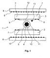
- Fig. 1 shows a cable comprising a textile composite 1 of a support layer 2 and a cover layer 3, wherein between the support layer 2 and the cover layer 3 at least one electrical line 4 is added and wherein the textile composite 1 is destructively flexible deformable.
- the electrical line 4 is electrically insulated from the carrier layer 2 and the cover layer 3 by an insulation 5.
- the carrier layer 2 and the cover layer 3 are reversibly compressible.
- the cable according to Fig. 1 is characterized by an elastic extensibility in the longitudinal direction, ie in the direction of the line 4, from.
- the carrier layer 2 and the cover layer 3 are connected by adhesive dots 6 at points.
- the carrier layer 2 and the cover layer 3 are configured as nonwovens.
- the nonwovens consist of split fibers, the made of bicomponent fibers.
- non-woven fabrics of the type having the trade designation EVOLON having a basis weight of 60 g / m 2 were used.
- the composite 1 therefore has porous regions which are made permeable to air.
- the porous regions 7 are at least between the adhesive dots 6.
- the composite 1 is embedded between two envelopes 8.
- the two envelopes 8 are also connected via adhesive dots 9 selectively with each other and with the composite 1.
- the electrical line 4 is designed as a strand 10.
- the strand 10 consists of a plurality of individual wires 11, which are twisted together.
- the electrical line 4, which is electrically insulated by the insulation 5, is surrounded by an electrical shield 12.
- the electrical shield 12 is designed in particular as a conductive shielding paste. In the conductive Ablepaste a bare wire 13 is embedded.
- the electrical shield 12 abuts directly on the electrical line 4 and is applied on the sides of the carrier layer 2 or cover layer 3, which face the electrical line 4.
- the carrier layer 2 and the cover layer 3 could also be configured as a foam, which exhibits sufficient compressibility and elastic extensibility in the longitudinal direction. The same applies to the enveloping layers 8. It is also conceivable to manufacture the enveloping layers 8 from a nonwoven fabric from which the carrier layer 2 or cover layer 3 is also made.
- Fig. 2 shows a cable with an analogous structure of the cable according to Fig. 1 , wherein as electrical line 4, a single wire 14 is used, which is surrounded by an insulation 5. The wire 14 is thereby protected against moisture.
- the cable shows according to Fig. 2 the same structure as the cable according to Fig. 1 , To avoid repetition, be on it noted that in the Fig. 1 and Fig. 2 like reference characters designate like components of the cable.
- Fig. 3 shows a cable comprising a textile composite 1 of a support layer 2 and a cover layer 3, wherein between the support layer 2 and the cover layer 3 at least one electrical line 4 is added and wherein the textile composite 1 is destructively flexible deformable.
- the electrical line 4 is electrically insulated from the carrier layer 2 and the cover layer 3 by an insulation 5.
- the carrier layer 2 and the cover layer 3 are reversibly compressible.
- the cable according to Fig. 3 is characterized by an elastic extensibility in the longitudinal direction.
- the carrier layer 2 and the cover layer 3 are selectively connected to each other by welding points 6a.
- the welding points 6a were generated by ultrasonic welding.
- the carrier layer 2 and the cover layer 3 are configured as nonwovens.
- the nonwovens consist of split fibers made of bicomponent fibers.
- nonwoven fabrics of the type for example of the trade name EVOLON having a basis weight of 60 g / m 2 were used.
- the composite 1 therefore has porous regions which are made permeable to air.
- the porous regions 7 are at least between the welding points 6a.
- the composite 1 is embedded between two envelopes 8.
- the two envelopes 8 are also connected via welding points 9a selectively with each other and with the textile composite 1.
- the welding points 9a were generated by ultrasonic welding.
- the electrical line 4 is designed in particular as a strand 10.
- the strand 10 consists of a plurality of individual wires 11, which are twisted together.
- the electrical line 4, which is electrically insulated by the insulation 5, is surrounded by an electrical shield 12.
- the electrical shield 12 is preferably designed as a conductive shielding paste. In the conductive Ablepaste a bare wire 13 is embedded.
- the electrical shield 12 is applied directly to the electrical line 4 and is applied to the sides of the carrier layer 2 and cover layer 3, which are facing the electrical line 4.
- each cable exhibits elastic extensibility at least in the longitudinal direction of up to 15% of the initial length.
- nonwoven fabrics for the carrier layer 2, the cover layer 3 and the enveloping layers 8 for example, a nonwoven fabric of the type EVOLON Freudenberg nonwovens KG, 69469 Weinheim, DE was used. The nonwovens showed a basis weight of 60 g / m 2 .
- a folded structure of the composite 1 can be used to adjust the length of the cable for different body sizes and body shapes, for example, for premature and neonatal patients on the one hand and for large and vigorous adult patients on the other hand.
- the length of the stretched composite 1 can thus be for example 15 to 50% greater than in the folded, unstretched state.
Landscapes
- Insulated Conductors (AREA)
Abstract
Description
Die Erfindung betrifft ein Kabel, umfassend einen textilen Verbund aus einer Trägerlage und einer Abdecklage, wobei zwischen der Trägerlage und der Abdecklage mindestens eine elektrische Leitung aufgenommen ist.The invention relates to a cable comprising a textile composite of a carrier layer and a cover layer, wherein at least one electrical line is received between the carrier layer and the cover layer.
Kabel der eingangs genannten Art, welche speziell geignet sind für elektromedizinische Anwendungen, wie beispielsweise Elektroden-Kabel für die Aufnahme von Elektrokardiogrammen (EKG), sind allgemein aus dem Stand der Technik bekannt. Die gattungsbildenden Kabel werden beispielsweise durch Laminieren von Trägerlagen und Abdecklagen in Kalandern hergestellt. Hierbei werden die Trägerlage und die Abdecklage häufig derart erwärmt, dass diese zumindest teilweise aufschmelzen und nach Erkalten einen steifen Verbund ausbilden. Eine solches Kabel ist beispielsweise aus der
Die gattungsbildenden Kabel sind jedoch für die Verwendung am menschlichen Körper nur wenig geeignet, da sie sich aufgrund ihrer Starre den Körperformen und Körpergrößen der unterschiedlichen Patienten nicht ausreichend anpassen können. Des Weiteren kann bei den aus dem Stand der Technik bekannten Kabeln nicht sichergestellt werden, dass eine zwischen Trägerlage und Abdecklage einlaminierte elektrische Leitung bei Auftreten von Körperfeuchtigkeiten keine elektrischen Kontakte zum menschlichen Körper herstellt.However, the generic cables are poorly suited for use on the human body because they can not adequately conform to the body shapes and body sizes of the different patients due to their rigidity. Furthermore, in the case of the cables known from the prior art, it can not be ensured that an electrical line laminated between the carrier layer and the cover layer does not produce electrical contacts to the human body when body moistures occur.
Zwar sind Kabel bekannt, die funktionsgerecht auf den menschlichen Körper aufgelegt werden können, jedoch sind diese häufig sehr teuer und müssen nach Gebrauch gereinigt werden. Die Reinigung und eventuelle Sterilisation des Kabels ist insbesondere im klinischen Bereich sehr aufwendig, da sichergestellt werden muss, dass keine Viren oder Keime am Kabel verbleiben. Gerade im klinischen Bereich ist es notwendig, Infektionen bei Patienten auszuschließen. Insbesondere sollen nosokomiale Infektionen ausgeschlossen werden.
Aus der
From the
Der Erfindung liegt die Aufgabe zu Grunde, ein Kabel der eingangs genannten Art derart auszugestalten und weiterzubilden, dass das Kabel nach kostengünstiger Fertigung einerseits bei eindringender Feuchtigkeit einen ausreichenden Schutz gegen Kurzschlüsse bietet und sich andererseits an gekrümmte und unregelmäßig ausgeformte Strukturen problemlos anpasst.The invention is based on the object to design a cable of the type mentioned and further, that the cable provides cost-effective production on the one hand with penetrating moisture sufficient protection against short circuits and on the other hand easily adapts to curved and irregularly shaped structures.
Die vorliegende Erfindung löst die zuvor genannte Aufgabe durch die Merkmale des Patentanspruchs 1.The present invention achieves the aforementioned object by the features of
Danach ist ein eingangs genanntes Kabel dadurch gekennzeichnet, dass der textile Verbund zerstörungsfrei flexibel deformierbar ist, wobei mindestens eine elektrische Leitung gegenüber der Trägerlage und der Abdecklage durch eine Isolation elektrisch isoliert ist..Thereafter, an initially mentioned cable is characterized in that the textile composite is non-destructively flexible deformable, wherein at least one electrical line with respect to the carrier layer and the cover layer is electrically insulated by an insulation.
Erfindungsgemäß ist zunächst erkannt worden, dass eine flexibel deformierbare Ausgestaltung der Trägerlage und/oder der Abdecklage erlaubt, das Kabel an unregelmäßig ausgeformte Strukturen anzuschmiegen, ohne Rückstellkräfte zu bewirken. Hierdurch ist das Kabel besonders geeignet, sich an einen menschlichen Körper anzulegen, ohne Druckstellen zu erzeugen. Durch eine Isolation der elektrischen Leitung gegenüber der Trägerlage und der Abdecklage wird sichergestellt, dass auch bei Eindringen von Feuchtigkeit in die Trägerlage und/oder die Abdecklage ein Stromfluss zum menschlichen Körper verhindert wird. Hierdurch ist das Kabel besonders geeignet, auf einen menschlichen Körper aufgelegt zu werden, da entstehender Schweiß oder Körperflüssigkeiten keinen Stromfluss bewirken können.According to the invention, it has first been recognized that a flexibly deformable configuration of the carrier layer and / or the cover layer allows the cable to be attached to irregularly shaped structures without causing restoring forces. As a result, the cable is particularly suitable for applying to a human body without generating pressure points. Insulation of the electrical line with respect to the carrier layer and the cover layer ensures that even if moisture penetrates into it the carrier layer and / or the cover layer, a flow of current to the human body is prevented. As a result, the cable is particularly suitable to be placed on a human body, as resulting sweat or body fluids can cause no flow of electricity.
Erfindungsgemäß ist insbesondere erkannt worden, dass sich das Kabel wie ein textiler Werkstoff anfühlt und sich quasi wie eine textile Stofflage verhält. Das Kabel ist in seiner Gesamtheit wie eine textile Stofflage zerknüllbar, deformierbar und verbiegbar.According to the invention, it has been recognized, in particular, that the cable feels like a textile material and behaves more or less like a textile material layer. The cable as a whole can be crumpled, deformed and bent like a textile fabric layer.
Erfindungsgemäß ist das Kabel gerade nicht starr ausgebildet, sondern in seiner Gesamtheit flexibel zerstörungsfrei deformierbar. Weiter ist das Kabel in seiner Gesamtheit trapierfähig. Das heißt, das Kabel ist in seiner Gesamtheit in der Lage, Falten zu schlagen, dreidimensionale Körper zu umhüllen und sich in seiner Gesamtheit wie ein textiler Werkstoff zu verhalten.According to the invention, the cable is not rigid at the moment, but in its entirety it can be flexibly deformed non-destructively. Furthermore, the cable is trapable in its entirety. That is, the cable as a whole is capable of folding, wrapping three-dimensional bodies, and behaving like a textile material in its entirety.
Folglich ist die eingangs genannte Aufgabe gelöst.Consequently, the object mentioned above is achieved.
Das Kabel könnte zumindest in Längsrichtung eine Dehnbarkeit von bis zu 15 % aufweisen. Hierdurch ist es möglich, das Kabel um Erhebungen und Wölbungen herumzulegen und geringfügig zu dehnen. Die Dehnbarkeit erlaubt des Weiteren eine zerstörungsfreie Deformierung des Kabels. Vor diesem Hintergrund ist denkbar, dass das Kabel sowohl elastisch dehnbar als auch inelastisch dehnbar ist. Bei der inelastischen Dehnung wird das Kabel aus einer Anfangslänge in eine Endlänge verbracht, wobei das Kabel die Endlänge im Wesentlichen beibehält.The cable could have a stretchability of up to 15% at least in the longitudinal direction. This makes it possible to put the cable around elevations and vaults and slightly stretch. The extensibility also allows a non-destructive deformation of the cable. Against this background, it is conceivable that the cable is both elastically extensible and inelastically extensible. With inelastic strain, the cable is moved from an initial length to an end length, with the cable substantially maintaining the final length.
Der Verbund könnte zumindest bereichsweise durch Perforationen oder poröse Bereiche luftdurchlässig ausgestaltet sein. Hierdurch kann das Kabel unmittelbar auf einen menschlichen Körper aufgelegt werden, ohne die Hautatmung negativ zu beeinflussen. Durch die Perforationen oder porösen Bereiche kann ein angenehmer Tragekomfort auf der menschlichen Haut bewirkt werden. Das Kabel zeigt deswegen eine besonders gute Atmungsaktivität, da es sich in seiner Gesamtheit wie ein textiler Werkstoff verhält und die Haut des menschlichen Körpers gerade nicht dicht abdeckt.The composite could be at least partially permeable to air through perforations or porous areas. As a result, the cable can be placed directly on a human body, without affecting the skin breathing negative. Through the perforations or porous areas can be a comfortable fit on the human skin be effected. The cable therefore shows a particularly good breathability, since it behaves in its entirety like a textile material and the skin of the human body just does not cover tightly.
Die Trägerlage und/oder die Abdecklage könnten punktuell miteinander verbunden sein. Durch die punktuelle Verbindung werden Bereiche geschaffen, die eine hohe Luftdurchlässigkeit zeigen. Des Weiteren bleibt der Verbund weich, versteift nicht und bleibt flexibel. Die punktuelle Verbindung kann durch Klebepunkte oder durch Schweißpunkte bewirkt werden. Im Bereich der Verschweißungen oder Verklebungen zeigt der Verbund keine oder eine nur sehr geringe Luftdurchlässigkeit, zwischen den Punkten werden jedoch luftdurchlässige Bereiche geschaffen. Je nach Wahl des Punktmusters oder Rasters kann die Luftdurchlässigkeit und Steifheit des Verbundes eingestellt werden.The carrier layer and / or the cover layer could be selectively connected to each other. The selective connection creates areas that show high air permeability. Furthermore, the composite remains soft, does not stiffen and remains flexible. The selective connection can be effected by adhesive dots or by welding points. In the field of welding or gluing the composite shows little or no air permeability, but air-permeable areas are created between the points. Depending on the choice of the dot pattern or grid, the air permeability and stiffness of the composite can be adjusted.
Vor diesem Hintergrund ist denkbar, dass die Trägerlage und/oder die Abdecklage als Vlies ausgestaltet ist. Ein Vlies ist aufgrund seiner porösen und lockeren Struktur zumindest geringfügig zumindest in seiner Dicke veränderbar und damit komprimierbar. Des Weiteren zeigen Vliese aufgrund ihrer porösen Struktur poröse Bereiche einer hohen Luftdurchlässigkeit. Aufgrund seiner leichten Komprimierbarkeit und hohen Luftdurchlässigkeit stellt ein Vlies einen hohen Tragekomfort auf der menschlichen Haut sicher.Against this background, it is conceivable that the carrier layer and / or the cover layer is designed as a fleece. Due to its porous and loose structure, a nonwoven is at least slightly variable in its thickness and therefore compressible. Furthermore, nonwovens show porous areas of high air permeability due to their porous structure. Due to its easy compressibility and high air permeability, a fleece ensures a high wearing comfort on the human skin.
Vor diesem Hintergrund ist denkbar, dass die Trägerlage und/oder die Abdecklage als Vlies aus Splitfasern ausgestaltet ist, die aus Bikomponentenfasern erzeugt wurden. Bikomponentenfasern zeigen häufig eine so genannte PIE-Struktur. Eine solche Bikomponentenfaser besteht aus einer Vielzahl von Elementarfasern, die im Querschnitt kuchenstückförmig ausgestaltet sind. Die Elementarfasern werden als Splitfasern bezeichnet und werden dadurch erzeugt, dass die Bikomponentenfaser in die Elementarfasern zerlegt wird. Das Zerlegen kann durch Wasserstrahlen erfolgen. Überraschend hat sich gezeigt, dass eine Trägerlage und/oder eine Abdecklage, die Spliffasern aufweist, einen besonders hohen Tragekomfort, eine hohe Elastizität und eine hohe Luftdurchlässigkeit zeigt. Vliese oder Vliesstoffe dieser Art eignen sich daher besonders für die Verwendung im hier beschriebenen Kabel.Against this background, it is conceivable that the carrier layer and / or the cover layer is designed as a fleece made of split fibers, which were produced from bicomponent fibers. Bicomponent fibers often show a so-called PIE structure. Such a bicomponent fiber consists of a plurality of elementary fibers, which are designed like a cake piece in cross section. The elementary fibers are called split fibers and are produced by breaking down the bicomponent fiber into the elementary fibers. The decomposition can be done by water jets. Surprisingly, it has been found that a carrier layer and / or a cover layer, the Spliffasern has, a particularly high wearing comfort, high elasticity and high air permeability shows. Nonwovens or nonwovens of this type are therefore particularly suitable for use in the cable described here.
Neben Geweben oder Gewirken haben sich Vliesstoffe als besonders vorteilhaft herausgestellt, da diese kostengünstig herstellbar sind. Neben dem genannten Vlies aus Splitfasern kann auch ein Vlies aus Stapelfasern oder aus Filamenten, d.h. Endlosfasern, verwendet werden, wobei diese Fasern in nicht gesplitteter Form vorliegen müssen.In addition to woven or knitted fabrics, nonwovens have proven to be particularly advantageous since they can be produced cost-effectively. In addition to the aforementioned fleece of split fibers, a fleece of staple fibers or of filaments, i. Endlosfasern be used, these fibers must be present in non-split form.
Der Verbund könnte zwischen zwei Hülllagen eingebettet sein. Hülllagen stabilisieren den Verbund und damit die elektrische Leitung bzw. die elektrischen Leitungen, die innerhalb des Verbundes verlaufen.The composite could be embedded between two envelopes. Hülllagen stabilize the composite and thus the electrical line or the electrical lines that run within the network.
Die zwei Hülllagen könnten punktuell miteinander verbunden sein. Durch die punktuelle Verbindung weist das Kabel eine hohe Flexibilität und Deformierbarkeit bzw. Biegbarkeit auf. Je nach Wahl des Punktrasters kann die Steifigkeit des Kabels und dessen Luftdurchlässigkeit eingestellt werden.The two envelopes could be connected to each other at points. Due to the selective connection, the cable has a high flexibility and deformability or flexibility. Depending on the choice of the dot matrix, the stiffness of the cable and its air permeability can be adjusted.
Mindestens eine elektrische Leitung könnte als leitfähige Paste ausgestaltet sein. Durch diese konkrete Ausgestaltung kann ein sehr flacher Verbund gefertigt werden. Vor diesem Hintergrund ist denkbar, dass die leitfähige Paste auch im erhärteten bzw. vernetzten Zustand eine hohe Elastizität und damit Dehnbarkeit zeigt. Eine solche Paste ist durch die
Mindestens eine elektrische Leitung könnte als Draht ausgestaltet sein. Drähte zeichnen sich durch eine hohe mechanische Stabilität aus, so dass das Kabel problemlos verwunden oder verbogen und insbesondere in Zickzackform, mäandrierend oder schlangenlinienförmig ausgebildet werden kann.At least one electrical line could be designed as a wire. Wires are characterized by a high mechanical stability, so that the cable easily wound or bent and can be formed in particular in a zigzag, meandering or serpentine.
Insbesondere zeichnen sich metallische Drähte durch eine hohe elektrische Leitfähigkeit aus.In particular, metallic wires are characterized by a high electrical conductivity.
Vor diesem Hintergrund ist auch denkbar, dass mindestens eine elektrische Leitung als Litze ausgestaltet ist. Eine Litze besteht aus einer Vielzahl von einzelnen metallischen Drähten, die miteinander verdrillt sind. Litzen haben sich als besonders vorteilhaft herausgestellt, da diese eine hohe Stabilität und Flexibilität aufweisen. Die verdrillten Drähte können zumindest geringfügig gegeneinander verschoben werden, so dass die Litze insgesamt eine hohe Flexibilität aufweist.Against this background, it is also conceivable that at least one electrical line is designed as a stranded wire. A strand consists of a multitude of individual metallic wires which are twisted together. Strands have proven to be particularly advantageous because they have a high stability and flexibility. The twisted wires can be at least slightly shifted from each other, so that the strand has a high overall flexibility.
Die elektrische Leitung ist in einer bevorzugten Ausbildung von einer elektrischen Abschirmung umgeben. Hierdurch ist sichergestellt, dass die Ströme oder elektrischen Signale der elektrischen Leitung nicht durch elektromagnetische Felder gestört werden. Insbesondere soll eine Einstrahlfestigkeit und ein Abstrahlverhalten bis 2,4 GHz gemäß DIN EN 60601 bei einem Grenzwert von 3 V/m realisiert werden.The electrical line is surrounded in a preferred embodiment of an electrical shield. This ensures that the currents or electrical signals of the electrical line are not disturbed by electromagnetic fields. In particular, a Einstrahlfestigkeit and a radiation behavior to 2.4 GHz according to DIN EN 60601 at a threshold of 3 V / m to be realized.
Vor diesem Hintergrund ist denkbar, dass die elektrische Abschirmung als elektrisch leitfähige Abschirmpaste ausgestaltet ist. Vorteilhaft wird hier als elektrische Abschirmung eine Paste verwendet, welche zum einen problemlos druckbar ist und sich zum anderen auch an poröse Strukturen sehr gut anschmiegen kann. Im flüssigen Zustand kann die Abschirmpaste geringe Unebenheiten auf der Trägerlage oder Abdecklage umfliessen und dadurch die elektrische Leitung zuverlässig abschirmen. Die Abschirmpaste kann des Weiteren die elektrische Leitung problemlos umfliessen und damit umschließen. Als elektrisch leitfähige Abschirmpaste kann die oben genannte leitfähige Paste verwendet werden. Vorteilhaft zeigt dann auch die leitfähige Abschirmpaste im erhärteten bzw. vernetzten Zustand eine hohe Flexibilität und Dehnbarkeit.Against this background, it is conceivable that the electrical shielding is configured as an electrically conductive shielding paste. Advantageously, a paste is used here as an electrical shield, which is printable on the one hand without problems and on the other can also very well cling to porous structures. In the liquid state, the shielding paste can flow around small unevenness on the carrier layer or cover layer and thereby reliably shield the electrical line. The shielding paste can also easily flow around the electrical line and thus enclose. As the electrically conductive shielding paste, the above-mentioned conductive paste can be used. Advantageously, then shows the conductive Abschirmpaste in the cured or crosslinked state, a high flexibility and elasticity.
Die Abschirmung könnte einen blanken Draht oder eine blanke Litze aufweisen. Der blanke Draht oder die blanke Litze könnte in die Abschirmung bzw. in die leitfähige Abschirmpaste eingelegt werden bzw. von dieser umschlossen sein. Hierdurch wird sichergestellt, dass alle Teile und Bereiche der Abschirmung miteinander elektrisch leitend verbunden sind. Eine hohe elektrische Leitfähigkeit ist wichtig für eine aktive Abschirmung. Bei einer aktiven Abschirmung liegt am blanken Draht ein Potential an, bei der passiven liegt am blanken Draht kein Potential an.The shield could have a bare wire or a bare strand. The bare wire or the bare strand could be inserted in the shield or in the conductive shielding paste or be enclosed by this. This ensures that all parts and areas of the shield are electrically connected to each other. High electrical conductivity is important for active shielding. With an active shield, there is a potential at the bare wire, at the passive one there is no potential at the bare wire.
Mindestens eine elektrische Leitung könnte zickzackförmig, wellenförmig oder mäanderförmig verlaufen. Vor diesem Hintergrund ist konkret denkbar, dass ein Draht in Wellenform oder in einer Zickzackform mit abgerundeten Zacken gefaltet im Verbund verläuft. Bei der Zickzackform ist darauf zu achten, dass der Draht nicht mit scharfen Zacken gefaltet wird, sondern an den Eckpunkten der Zacken im Wesentlichen gebogen vorliegt. Hierdurch wird vermieden, dass der Draht zerstört wird. Hierdurch ist sichergestellt, dass die elektrische Leitung in Längsrichtung dehnbar ist. Durch eine Zugkraft kann eine wellenförmig vorliegende elektrische Leitung nahezu glatt gezogen werden, so dass die elektrische Leitung insgesamt eine hohe Dehnbarkeit in Längsrichtung aufweist.At least one electrical line could be zigzag, wavy or meandering. Against this background, it is conceivable that a wire in a wave form or in a zigzag shape with rounded teeth runs folded in the composite. In the zigzag form, make sure that the wire is not folded with sharp prongs, but is substantially bent at the corner points of the prongs. This will prevent the wire from being destroyed. This ensures that the electrical line is stretchable in the longitudinal direction. By a tensile force, a wave-shaped electrical line can be pulled almost smooth, so that the electrical line has a high extensibility in the longitudinal direction.
Das hier beschriebene Kabel weist in vorteilhafter Weise eine Durchschlagsfestigkeit von mindestens 5 kV zwischen elektrischer Leitung und einer Kabeloberfläche auf. Durch diese konkrete Ausgestaltung ist das Kabel geeignet, um mit einem menschlichen Körper in Kontakt gebracht zu werden. Dabei liegt die Kabeloberfläche direkt auf dem menschlichen Körper auf. Durch die hohe Durchschlagfestigkeit wird der menschliche Körper vor einem Stromfluss oder einem elektrischen Schlag geschützt. Ein Kabel dieser Ausgestaltung kann problemlos während einer Defibrillation am menschlichen Körper verbleiben, da es durch die während die Defibrillation auftretenden hohen Spannungen und Ströme im Wesentlichen nicht in seiner Funktion gestört wird. Die genannte Durchschlagsfestigkeit könnte auch zwischen den elektrischen Leitungen und der elektrischen Abschirmung und/ oder den elektrischen Leitungen und der Kabeloberfläche bestehen.The cable described herein advantageously has a dielectric strength of at least 5 kV between electrical conduction and a cable surface. By this specific embodiment, the cable is suitable for being brought into contact with a human body. The cable surface rests directly on the human body. The high dielectric strength protects the human body from a current flow or electric shock. A cable of this design can easily remain on the human body during defibrillation, since it is not disturbed in its function by the high voltages and currents occurring during defibrillation. The above dielectric strength could also be between the consist of electrical lines and the electrical shield and / or the electrical lines and the cable surface.
Das Kabel weist in einer alternativen Ausführungsform elektrische Leitungen auf, die in zumindest bereichsweise voneinander getrennten oder trennbaren Strängen verlaufen. Hierdurch ist eine Dimensionsanpassung des Kabels problemlos möglich, da jeder Strang einem anderen Punkt im Raum zuordnenbar ist.In an alternative embodiment, the cable has electrical lines which run in strands which are at least partially separated or separable from one another. As a result, a dimension adaptation of the cable is easily possible because each strand is assignable to another point in the room.
Die Stränge könnten durch Perforationen oder Materialschwächungen voneinander getrennt oder trennbar sein, um eine Längenanpassung des Kabels vorzunehmen. Die Perforationen oder Materialschwächungen erlauben ein einfaches Auseinanderreissen einzelner Bereiche des Kabels.The strands could be separated or separable from each other by perforations or weakening of the material to make length adjustment of the cable. The perforations or material weakenings allow easy separation of individual areas of the cable.
Das hier beschriebene Kabel könnte mehrere elektrische Leitungen aufweisen, die im Wesentlichen parallel zueinander verlaufen. Dabei ist denkbar, dass einzelne oder mehrere Leitungen in Strängen verlaufen, die voneinander zumindest bereichsweise getrennt sind. Die bereichsweise Abtrennung der Stränge kann durch Schlitze erfolgen, die im Verbund bzw. in den Hülllagen des Kabels ausgebildet sind. Die im Verbund bzw. in den Hülllagen eingebrachten Schlitze sind speziell als Bereiche vermindeter Materialstärke ausgebildet. Die Bereiche vermindeter Materialstärke könnten durch einen Ultraschallschweißprozess vorgesehen werden. Durch die Anordnung dieser materialgeschwächten Bereiche ist es problemlos möglich, das Kabel an diesen Bereichen aufzureißen und dadurch einzelne voneinander separierte Stränge zu schaffen. Hierdurch kann das Kabel an unterschiedliche Geometrien und Dimensionen längenangepasst werden. Insbesondere ist denkbar, dass einzelne Bereiche des Kabels voneinander getrennt werden, um sich in verschiedene Raumrichtungen zu erstrecken, während zusammenhängende Bereiche sich gemeinsam in einer Raumrichtung erstrecken.The cable described herein could have a plurality of electrical leads that are substantially parallel to each other. It is conceivable that single or multiple lines run in strands, which are separated from each other at least partially. The regional separation of the strands can be effected by slots which are formed in the composite or in the enveloping layers of the cable. The slots introduced in the composite or in the sheath layers are specially designed as areas of reduced material thickness. The areas of reduced material thickness could be provided by an ultrasonic welding process. The arrangement of these material-weakened areas, it is easily possible to tear the cable at these areas and thereby create individual separated strands. This allows the cable length to be adapted to different geometries and dimensions. In particular, it is conceivable that individual regions of the cable are separated from one another in order to extend in different spatial directions, while contiguous regions extend together in a spatial direction.
Vor diesem Hintergrund ist auch denkbar, einzelne Bereiche des Kabels durch Druckknöpfe oder Klettverschlüsse miteinander unter Ausbildung von Schlaufen im Kabel zu verbinden. Diese Verbindung kann im Bedarfsfall gelöst werden, um eine Verlängerung des Kabels herbeizuführen. Das Kabel kann auch, quasi wie eine Girlande, wellenförmig gestaucht sein, wobei es an einem Richtdraht zur Verlängerung gereckt werden kann.
Das gefaltete Kabel kann auch durch punktuelles Ultraschall-Schweißen zum Beispiel am Kabelrand zusammengehalten werden. Wenn diese Verbindung lagenweise erfolgt, kann man die Kabellänge sehr praktisch stufenweise in der Länge einstellen.Against this background is also conceivable, individual areas of the cable by snap fasteners or Velcro fastenings with each other under training of To connect loops in the cable. If necessary, this connection can be loosened to bring about an extension of the cable. The cable can also, like a garland, be upset wavy, where it can be stretched on a wire for extension.
The folded cable can also be held together by selective ultrasonic welding, for example, at the cable edge. If this connection is made in layers, you can adjust the length of the cable very practically stepwise in length.
Das hier beschriebene Kabel könnte speziell beispielsweise fünf elektrische Leitungen aufweisen, die in zwei Strängen verteilt sind. Dabei könnten zwei Leitungen in einem ersten Strang und drei Leitungen in einem zweiten Strang verlaufen. Die Stränge könnten gegeneinander verbiegbar und dehnbar ausgestaltet sein. Durch diese konkrete Ausgestaltung ist ein Kabel erzeugbar, welches mindestens drei Enden aufweist. Ein solches Kabel kann auf eine Fläche, insbesondere eine gewölbte Fläche, aufgelegt werden und an unterschiedlichen Punkten der Fläche elektrische Signale erfassen oder weiterleiten. Das vorgenannte Kabel kann insbesondere auf einem menschlichen Körper aufgelegt werden, um ein Elektrokardiogramm (EKG) zu erfassen. Dabei könnte ein Ende des Kabels mit einem Gerät zur Erfassung eines Elektrokardiogramms verbunden sein, wobei die beiden anderen Enden mit Elektroden verbunden sind, die auf dem menschlichen Körper aufliegen. Das hier beschriebene Kabel weist eine elastische Dehnbarkeit in Längsrichtung von bis zu 15 % auf.
In einer speziellen Ausführungsform ist das Kabel zusätzlich derart gefaltet, dass die Gesamtlänge des gestreckten Verbundes 1 15 bis 50% größer ist als die Länge des Verbundes 1 im gefalteten, nicht gestreckten Zustand.Specifically, the cable described herein could have, for example, five electrical leads distributed in two strands. In this case, two lines could run in a first strand and three lines in a second strand. The strands could be made bendable and stretchable against each other. By this specific embodiment, a cable can be generated, which has at least three ends. Such a cable can be placed on a surface, in particular a curved surface, and capture or relay electrical signals at different points on the surface. In particular, the aforementioned cable can be placed on a human body to detect an electrocardiogram (ECG). In this case, one end of the cable could be connected to a device for acquiring an electrocardiogram, the other two ends being connected to electrodes resting on the human body. The cable described herein has a longitudinal elastic stretchability of up to 15%.
In a special embodiment, the cable is additionally folded in such a way that the total length of the stretched
Das Kabel ist vorzugsweise silikonfrei, latexfrei oder PVC-frei ausgestaltet. Durch diese konkrete Ausgestaltung eignet es sich in besonderer Weise für eine unmittelbare Auflage auf der menschlichen Haut.The cable is preferably silicone-free, latex-free or PVC-free. By this specific embodiment, it is particularly suitable for an immediate edition on the human skin.
Das Kabel könnte eine Biegewechselfestigkeit von mindestens 10.000 Zyklen aufweisen. Ein Kabel dieser Festigkeit kann problemlos im medizinischen Bereich eingesetzt werden, da es den dortigen mechanischen Anforderungen standhält.The cable could have a bending fatigue strength of at least 10,000 cycles. A cable of this strength can be easily used in the medical field, as it withstands the mechanical requirements there.
Ein Kabel der hier beschriebenen Art eignet sich in besonderer Weise als Einwegkabel in einer Anordnung zur Erfassung eines Elektrokardiogramms. Das hier beschriebene Kabel zeichnet sich durch eine hohe Flexibilität aus. Insbesondere in Längsrichtung kann das Kabel eine Dehnbarkeit von bis zu 15 % aufweisen. Diese Dehnbarkeit kann sowohl elastisch als auch inelastisch sein. Des Weiteren ist das hier beschriebene Kabel kostengünstig herstellbar und kann daher nach Einmalgebrauch weggeworfen werden. Eine aufwendige Reinigung des Kabels, um Infektionen der Patienten zu verhindern, erübrigt sich. Die Isolation der elektrischen Leitung gegenüber der Trägerlage und der Abdecklage macht das Kabel gegen Feuchtigkeit unempfindlich. Die reversible Komprimierbarkeit der Trägerlage und/oder der Abdecklage bewirkt einen hohen Tragekomfort. Daher eignet sich das Kabel in besonderem Maße für die Auflage auf den menschlichen Körper.A cable of the type described here is particularly suitable as a disposable cable in an arrangement for detecting an electrocardiogram. The cable described here is characterized by a high degree of flexibility. Especially in the longitudinal direction, the cable can have a stretchability of up to 15%. This extensibility can be both elastic and inelastic. Furthermore, the cable described here is inexpensive to produce and can therefore be thrown away after a single use. A costly cleaning of the cable to prevent infections of patients, is unnecessary. The insulation of the electrical line with respect to the carrier layer and the cover layer makes the cable insensitive to moisture. The reversible compressibility of the carrier layer and / or the cover layer causes a high wearing comfort. Therefore, the cable is particularly suitable for resting on the human body.
Das hier beschriebene Kabel ist vorzugsweise plasma beschichtet. Eine Plasmabeschichtung bewirkt eine wasser- bzw. flüssigkeitsabweisende Ausrüstung des Kabels unter Beibehaltung dessen Atmungsaktivität. Als Precursor bei der Plasmabeschichtung könnten insbesondere Fluorcarbone, Kohlenwasserstoffe oder Siloxane verwendet werden. Selbstverständlich ist auch denkbar, Mischungen aus den vorgenannten Stoffen als Precursor einzusetzen. Diese Stoffe haben sich als besonders geeignet erwiesen, das Kabel hydrophob auszurüsten und dennoch eine hohe Atmungsaktivität beizubehalten.The cable described here is preferably plasma-coated. A plasma coating causes a water- or liquid-repellent equipment of the cable while maintaining its breathability. In particular, fluorocarbons, hydrocarbons or siloxanes could be used as precursors in the plasma coating. Of course, it is also conceivable to use mixtures of the abovementioned substances as precursor. These fabrics have been found to be particularly suitable for rendering the cable hydrophobic while still maintaining high breathability.
Es gibt nun verschiedene Möglichkeiten, die Lehre der vorliegenden Erfindung in vorteilhafter Weise auszugestalten und weiterzubilden. Dazu ist einerseits auf die nachgeordneten Ansprüche, andererseits auf die nachfolgende Erläuterung bevorzugter Ausführungsbeispiele der erfindungsgemäßen Lehre anhand der Zeichnung zu verweisen.There are now various possibilities for designing and developing the teaching of the present invention in an advantageous manner. This is on the one hand to the subordinate claims, on the other hand, the following Explanation of preferred embodiments of the teaching of the invention with reference to the drawings.
In Verbindung mit der Erläuterung der bevorzugten Ausführungsbeispiele anhand der Zeichnung werden auch im Allgemeinen bevorzugte Ausgestaltungen und Weiterbildungen der Lehre erläutert.In conjunction with the explanation of the preferred embodiments with reference to the drawings, generally preferred embodiments and developments of the teaching are explained.
In der Zeichnung zeigen
- Fig. 1
- ein Kabel, bei welchem die elektrische Leitung als Litze ausgebildet ist,
- Fig. 2
- ein Kabel, bei welchem die elektrische Leitung als Draht ausgebildet ist, und
- Fig. 3
- ein Kabel, bei welchem der Verbund durch Schweisspunkte erzeugt ist, die durch ein Ultraschallschweissverfahren erzeugt wurden.
- Fig. 1
- a cable in which the electrical line is designed as a strand,
- Fig. 2
- a cable in which the electric wire is formed as a wire, and
- Fig. 3
- a cable in which the composite is produced by welding points produced by an ultrasonic welding process.
Der Verbund 1 ist zwischen zwei Hülllagen 8 eingebettet. Die zwei Hülllagen 8 sind ebenfalls über Klebepunkte 9 punktuell miteinander und mit dem Verbund 1 verbunden.The
Die elektrische Leitung 4 ist als Litze 10 ausgestaltet. Die Litze 10 besteht aus einer Vielzahl von einzelnen Drähten 11, die miteinander verdrillt sind. Die elektrische Leitung 4, die durch die Isolation 5 elektrisch isoliert ist, ist von einer elektrischen Abschirmung 12 umgeben. Die elektrische Abschirmung 12 ist insbesondere als leitfähige Abschirmpaste ausgestaltet. In die leitfähige Abschirmpaste ist ein blanker Draht 13 eingebettet. Die elektrische Abschirmung 12 liegt unmittelbar an der elektrischen Leitung 4 an und ist auf den Seiten der Trägerlage 2 bzw. Abdecklage 3 aufgebracht, die der elektrischen Leitung 4 zugewandt sind.The
Die Trägerlage 2 und die Abdecklage 3 könnten auch als Schaumstoff ausgestaltet sein, der eine hinreichende Komprimierbarkeit und elastische Dehnbarkeit in Längsrichtung zeigt. Das Gleiche gilt für die Hülllagen 8. Denkbar ist, die Hülllagen 8 ebenfalls aus einem Vliesstoff zu fertigen, aus dem auch die Trägerlage 2 bzw. die Abdecklage 3 gefertigt ist.The
Der Verbund 1 ist zwischen zwei Hülllagen 8 eingebettet. Die zwei Hülllagen 8 sind ebenfalls über Schweisspunkte 9a punktuell miteinander und mit dem textilen Verbund 1 verbunden. Die Schweisspunkte 9a wurden durch Ultraschallschweissen erzeugt.The
Die elektrische Leitung 4 ist insbesondere als Litze 10 ausgestaltet. Die Litze 10 besteht aus einer Vielzahl von einzelnen Drähten 11, die miteinander verdrillt sind. Die elektrische Leitung 4, die durch die Isolation 5 elektrisch isoliert ist, ist von einer elektrischen Abschirmung 12 umgeben. Die elektrische Abschirmung 12 ist vorzugsweise als leitfähige Abschirmpaste ausgestaltet. In die leitfähige Abschirmpaste ist ein blanker Draht 13 eingebettet. Die elektrische Abschirmung 12 liegt unmittelbar an der elektrischen Leitung 4 an und ist auf den Seiten der Trägerlage 2 bzw. Abdecklage 3 aufgebracht, die der elektrischen Leitung 4 zugewandt sind.The
Die in den
Zusätzlich zur elastischen Dehnbarkeit des Kabels kann durch eine gefaltete Struktur des Verbundes 1 eine Anpassung der Länge des Kabels für verschiedene Körpergrößen und Körperformen erreicht werden, zum Beispiel für früh- und neugeborene Patienten einerseits und für große und kräftige erwachsene Patienten andererseits. Die Länge des gestreckten Verbundes 1 kann so beispielsweise 15 bis 50% größer sein als im gefalteten, ungestreckten Zustand.In addition to the elastic extensibility of the cable, a folded structure of the composite 1 can be used to adjust the length of the cable for different body sizes and body shapes, for example, for premature and neonatal patients on the one hand and for large and vigorous adult patients on the other hand. The length of the stretched
Hinsichtlich weiterer vorteilhafter Ausgestaltungen und Weiterbildungen der erfindungsgemäßen Lehre wird einerseits auf den allgemeinen Teil der Beschreibung und andererseits auf die beigefügten Patentansprüche verwiesen.With regard to further advantageous embodiments and developments of the teaching of the invention reference is made on the one hand to the general part of the description and on the other hand to the appended claims.
Abschließend sei ganz besonders hervorgehoben, dass die zuvor gewählten Ausführungsbeispiele lediglich zur Beschreibung der erfindungsgemäßen Lehre dienen, diese jedoch nicht auf diese Ausführungsbeispiele einschränken.Finally, it should be particularly emphasized that the previously selected embodiments merely serve to describe the teaching of the invention, but not limit these to these embodiments.
Claims (16)
Applications Claiming Priority (1)
| Application Number | Priority Date | Filing Date | Title |
|---|---|---|---|
| DE102009005416 | 2009-01-19 |
Publications (2)
| Publication Number | Publication Date |
|---|---|
| EP2209126A2 true EP2209126A2 (en) | 2010-07-21 |
| EP2209126A3 EP2209126A3 (en) | 2012-04-04 |
Family
ID=42109965
Family Applications (1)
| Application Number | Title | Priority Date | Filing Date |
|---|---|---|---|
| EP09012223A Withdrawn EP2209126A3 (en) | 2009-01-19 | 2009-09-25 | Flexible deformable cable with textile compound for electromedical assemblies |
Country Status (3)
| Country | Link |
|---|---|
| US (1) | US20100185107A1 (en) |
| EP (1) | EP2209126A3 (en) |
| CN (1) | CN101783202A (en) |
Families Citing this family (4)
| Publication number | Priority date | Publication date | Assignee | Title |
|---|---|---|---|---|
| DE102011078734A1 (en) * | 2011-07-06 | 2013-01-10 | Robert Bosch Gmbh | Component e.g. fuel distributor of fuel injection system for motor vehicle, has electrical line that is applied by plasma coating to base portion and provided with electrical isolating protecting layer |
| JP5920181B2 (en) * | 2012-11-15 | 2016-05-18 | 住友電装株式会社 | Wire harness and method for manufacturing wire harness |
| FR3040826B1 (en) * | 2015-09-04 | 2017-08-18 | Renault Sas | PROTECTIVE DEVICE FOR POWER SUPPLY CABLES OF AN ELECTRIC MOTOR POWERTRAIN |
| CN111281612B (en) * | 2019-12-30 | 2022-05-27 | 雅博尼西医疗科技(苏州)有限公司 | Prosthesis with porous surface structure |
Citations (2)
| Publication number | Priority date | Publication date | Assignee | Title |
|---|---|---|---|---|
| US5341806A (en) | 1991-04-18 | 1994-08-30 | Physio-Control Corporation | Multiple electrode strip |
| DE102004007875B3 (en) | 2004-02-17 | 2005-09-15 | Carl Freudenberg Kg | Three-dimensionally shaped flat cable |
Family Cites Families (13)
| Publication number | Priority date | Publication date | Assignee | Title |
|---|---|---|---|---|
| US2434793A (en) * | 1944-11-11 | 1948-01-20 | Edward B Feaster | Electric cord |
| GB973211A (en) * | 1959-12-11 | 1964-10-21 | Eisler Paul | Electric tape cables |
| US4281211A (en) * | 1979-04-13 | 1981-07-28 | Southern Weaving Company | Woven cover for electrical transmission cable |
| US4353372A (en) * | 1980-02-11 | 1982-10-12 | Bunker Ramo Corporation | Medical cable set and electrode therefor |
| US5502287A (en) * | 1993-03-10 | 1996-03-26 | Raychem Corporation | Multi-component cable assembly |
| US5552565A (en) * | 1995-03-31 | 1996-09-03 | Hewlett-Packard Company | Multiconductor shielded transducer cable |
| FI962544A (en) * | 1996-06-19 | 1997-12-20 | Iws International Inc | Flat cable and method of making it |
| DE19728940A1 (en) * | 1997-07-07 | 1999-01-14 | Alsthom Cge Alcatel | Cable with conductors and conducting sheath |
| US6730622B2 (en) * | 1999-12-21 | 2004-05-04 | The Procter & Gamble Company | Electrical cable |
| US7091422B1 (en) * | 2005-01-28 | 2006-08-15 | Multek Flexible Circuits, Inc. | Flexible flat cable with insulating layer having distinct adhesives on opposing faces |
| CN100553032C (en) * | 2005-03-30 | 2009-10-21 | 松下电器产业株式会社 | Transmission line is right |
| TWM342597U (en) * | 2008-05-08 | 2008-10-11 | Tennrich Int Corp | Easily flexible transmission line with improved characteristic impedance |
| DE102009005404A1 (en) * | 2009-01-19 | 2010-07-22 | Carl Freudenberg Kg | Cable for use as nonreturnable cable in arrangement for recording electrocardiogram, has textile composite made of support layer, and electric circuit |
-
2009
- 2009-09-25 EP EP09012223A patent/EP2209126A3/en not_active Withdrawn
-
2010
- 2010-01-15 US US12/688,174 patent/US20100185107A1/en not_active Abandoned
- 2010-01-19 CN CN201010119385A patent/CN101783202A/en active Pending
Patent Citations (2)
| Publication number | Priority date | Publication date | Assignee | Title |
|---|---|---|---|---|
| US5341806A (en) | 1991-04-18 | 1994-08-30 | Physio-Control Corporation | Multiple electrode strip |
| DE102004007875B3 (en) | 2004-02-17 | 2005-09-15 | Carl Freudenberg Kg | Three-dimensionally shaped flat cable |
Also Published As
| Publication number | Publication date |
|---|---|
| EP2209126A3 (en) | 2012-04-04 |
| US20100185107A1 (en) | 2010-07-22 |
| CN101783202A (en) | 2010-07-21 |
Similar Documents
| Publication | Publication Date | Title |
|---|---|---|
| EP3051926B1 (en) | Plasma generating device, plasma generating system, method of generating plasma and method for disinfecting surfaces | |
| EP3292885B1 (en) | Stretchable electrode conductor assembly and medical implant | |
| DE60307063T2 (en) | CONDUCTIVE FIBER | |
| WO2014090927A1 (en) | Textile-based electrode, method for producing and using same | |
| DE112011102168B4 (en) | Medical Electrical Cable Assembly and Use, EKG Cable and Electrocardiography (ECG) Assembly | |
| DE102011101583B4 (en) | Electrode for transcutaneous transmission of electrical signals and method for producing such | |
| DE202006007226U1 (en) | textile electrode | |
| DE102019103934B3 (en) | Spacer fabric section, method for forming a heating system from a spacer fabric section and heatable interior component for a motor vehicle | |
| DE102016109568B4 (en) | Electro-muscle stimulation electrode, garment, method of making a garment and use of an electrode | |
| EP3784327B1 (en) | Electrode body of an electrode assembly and electrode assembly for electrical stimulation, and method for producing an electrode assembly | |
| EP2209126A2 (en) | Flexible deformable cable with textile compound for electromedical assemblies | |
| EP3541469B1 (en) | Implantable electric multi-pole connection structure | |
| EP0954266B1 (en) | Self-adhesive ready-made bandage for restricting stretching or bending of the metacarpophalangeal joint and of the wrist | |
| WO2008022482A1 (en) | Textile electrode device, in particular for multi-channel electrostimulation or electrophysiological measurements, and method for its production | |
| EP3756725A1 (en) | Implantable electrode line with braided conductors | |
| DE102013219513A1 (en) | Sensor for contactless electrocardiographic measurement, sensor array and seat or couch | |
| DE102008048984A1 (en) | Sensor for detecting electrical biopotential, particularly for use in medical apparatus, prosthesis liner, sleeve or belt, has substrate with multiple needles, where shell extends partially over main surface of substrate | |
| DE202013100966U1 (en) | Three-dimensional, conductive fabric arrangement | |
| DE102009014697A1 (en) | Heating element and its use | |
| DE102009005404A1 (en) | Cable for use as nonreturnable cable in arrangement for recording electrocardiogram, has textile composite made of support layer, and electric circuit | |
| DE102004022373B4 (en) | Multilayer sewn system | |
| EP2456282A1 (en) | Distance knitted fabric for heating purposes, method for producing same and use of same | |
| DE102019103935B4 (en) | Heating insert in the form of a knitted spacer section and a heatable interior component | |
| EP3164067B1 (en) | Device for an impedance tomograph | |
| DE102009016380B4 (en) | tissue |
Legal Events
| Date | Code | Title | Description |
|---|---|---|---|
| PUAI | Public reference made under article 153(3) epc to a published international application that has entered the european phase |
Free format text: ORIGINAL CODE: 0009012 |
|
| AK | Designated contracting states |
Kind code of ref document: A2 Designated state(s): AT BE BG CH CY CZ DE DK EE ES FI FR GB GR HR HU IE IS IT LI LT LU LV MC MK MT NL NO PL PT RO SE SI SK SM TR |
|
| AX | Request for extension of the european patent |
Extension state: AL BA RS |
|
| 17P | Request for examination filed |
Effective date: 20100705 |
|
| RAP1 | Party data changed (applicant data changed or rights of an application transferred) |
Owner name: DRAEGER MEDICAL GMBH |
|
| PUAL | Search report despatched |
Free format text: ORIGINAL CODE: 0009013 |
|
| AK | Designated contracting states |
Kind code of ref document: A3 Designated state(s): AT BE BG CH CY CZ DE DK EE ES FI FR GB GR HR HU IE IS IT LI LT LU LV MC MK MT NL NO PL PT RO SE SI SK SM TR |
|
| AX | Request for extension of the european patent |
Extension state: AL BA RS |
|
| RIC1 | Information provided on ipc code assigned before grant |
Ipc: H01B 7/08 20060101ALI20120229BHEP Ipc: H01B 7/04 20060101AFI20120229BHEP |
|
| STAA | Information on the status of an ep patent application or granted ep patent |
Free format text: STATUS: THE APPLICATION IS DEEMED TO BE WITHDRAWN |
|
| 18D | Application deemed to be withdrawn |
Effective date: 20121005 |