EP2202906B1 - Data-aided signal-to-noise ratio estimate for M-DPSK modulation systems with division of the received samples into blocks - Google Patents
Data-aided signal-to-noise ratio estimate for M-DPSK modulation systems with division of the received samples into blocks Download PDFInfo
- Publication number
- EP2202906B1 EP2202906B1 EP20090180214 EP09180214A EP2202906B1 EP 2202906 B1 EP2202906 B1 EP 2202906B1 EP 20090180214 EP20090180214 EP 20090180214 EP 09180214 A EP09180214 A EP 09180214A EP 2202906 B1 EP2202906 B1 EP 2202906B1
- Authority
- EP
- European Patent Office
- Prior art keywords
- signal
- noise ratio
- estimation
- snr
- channel
- Prior art date
- Legal status (The legal status is an assumption and is not a legal conclusion. Google has not performed a legal analysis and makes no representation as to the accuracy of the status listed.)
- Active
Links
- 230000005540 biological transmission Effects 0.000 claims description 32
- 238000000034 method Methods 0.000 claims description 12
- 230000001427 coherent effect Effects 0.000 claims description 5
- 238000004364 calculation method Methods 0.000 claims description 4
- 230000008054 signal transmission Effects 0.000 claims 3
- 238000005070 sampling Methods 0.000 description 8
- 230000006735 deficit Effects 0.000 description 5
- 230000006870 function Effects 0.000 description 5
- 230000000694 effects Effects 0.000 description 4
- 230000000750 progressive effect Effects 0.000 description 4
- 230000003044 adaptive effect Effects 0.000 description 3
- 238000004891 communication Methods 0.000 description 3
- 230000003595 spectral effect Effects 0.000 description 2
- 239000000654 additive Substances 0.000 description 1
- 230000000996 additive effect Effects 0.000 description 1
- 230000003321 amplification Effects 0.000 description 1
- 239000000969 carrier Substances 0.000 description 1
- 238000006243 chemical reaction Methods 0.000 description 1
- 230000007423 decrease Effects 0.000 description 1
- 230000003111 delayed effect Effects 0.000 description 1
- 238000003199 nucleic acid amplification method Methods 0.000 description 1
- 238000011084 recovery Methods 0.000 description 1
- 230000001131 transforming effect Effects 0.000 description 1
Images


Classifications
-
- H—ELECTRICITY
- H04—ELECTRIC COMMUNICATION TECHNIQUE
- H04L—TRANSMISSION OF DIGITAL INFORMATION, e.g. TELEGRAPHIC COMMUNICATION
- H04L27/00—Modulated-carrier systems
- H04L27/18—Phase-modulated carrier systems, i.e. using phase-shift keying
- H04L27/22—Demodulator circuits; Receiver circuits
- H04L27/233—Demodulator circuits; Receiver circuits using non-coherent demodulation
- H04L27/2331—Demodulator circuits; Receiver circuits using non-coherent demodulation wherein the received signal is demodulated using one or more delayed versions of itself
-
- H—ELECTRICITY
- H04—ELECTRIC COMMUNICATION TECHNIQUE
- H04B—TRANSMISSION
- H04B17/00—Monitoring; Testing
- H04B17/30—Monitoring; Testing of propagation channels
- H04B17/309—Measuring or estimating channel quality parameters
-
- H—ELECTRICITY
- H04—ELECTRIC COMMUNICATION TECHNIQUE
- H04L—TRANSMISSION OF DIGITAL INFORMATION, e.g. TELEGRAPHIC COMMUNICATION
- H04L1/00—Arrangements for detecting or preventing errors in the information received
- H04L1/20—Arrangements for detecting or preventing errors in the information received using signal quality detector
- H04L1/206—Arrangements for detecting or preventing errors in the information received using signal quality detector for modulated signals
Definitions
- the present invention relates to a method for estimating the signal-to-noise ratio for packet transmission and reception systems of signals based on M-DPSK modulations, in particular for systems based on receivers of the non-coherent type with differential demodulator, and an apparatus thereof.
- the adaptive modulation is reacting to the changes of the channel conditions by using strong modulation schemes in the case of bad channel conditions and employing less strong modulation schemes in the case of good channel conditions for increasing the transmission speed.
- the adaptive modulations may be employed both in single carrier systems and in multiple carrier systems, in both cases a reliable estimation of the channel conditions is needed, for example an estimation of the signal-to-noise ratio (SNR), in order to choose the modulation to be employed.
- SNR signal-to-noise ratio
- the apparatuses for estimating the signal-to-noise ratio or SNR estimators may be divided in two categories: "data aided” estimators and “not data aided” estimators i.e. the estimators acting on a known data sequence and those acting on an unknown data sequence.
- the present data aided SNR estimators applied to non-coherent receivers at the input of a differential demodulator do not allow good estimations of the signal-to-noise ratio to be obtained in the presence of impairments that cause a progressive phase shifting of the received constellation symbols.
- An example of such impairments is the presence of carrier frequency offsets, between transmitter and receiver, on the carrier frequency.
- the present data aided SNR estimators applied to non-coherent receivers at the output of a differential demodulator are stronger against those impairments, as the frequency offsets but more sensitive to the noise.
- the system comprises the packet transmission of the signal with a sequence of N known symbols, with N positive integer number and the transmission comprises a M-PSK modulation of the signal to transmit by means of a M-PSK mapper, the transmission of the M-PSK modulated signal through a channel having constant gain over all the N symbols and in presence of noise with null average, and the reception of the signal at the output of the channel.
- An example of such impairments is the pretence of a carrier frequency offset.
- an apparatus for estimating the signal-to-noise ratio may be provided as set forth in the claim 6.
- FIG. 1 shows the equivalent base-band scheme of a pass-band packet transmission and reception system of signals with a single carrier.
- the M-DPSK modulator 1 comprises an M-PSK bit mapper 2 where M is the modulation order, i.e. the number of possible constellation symbols.
- the receiver retrieves the transmitted data using the phase difference between consecutive samples without needing to retrieve the phase offset introduced by the channel and the phase offset between transmitter and receiver on the carrier frequency.
- the signal at the output of the channel 5 still has a PSK structure
- noise is added to the signal s ( t ), preferably an additive white Gaussian noise w ( t ) (AWGN) having a null average with double-sided spectral power density of N 0 /2.
- AWGN additive white Gaussian noise w ( t )
- the sampled signal r k is processed by a M-DPSK differential demodulator module 7 and sent to an inverted bit mapper 8 providing decisions on the received bits q i .
- the demodulator multiplies the sampled signal r k by its delayed and conjugated version r k - 1 * .
- the useful term i.e. the term G 2 ⁇ a k ⁇ a k - 1 * ⁇ e j ⁇ 2 ⁇ ⁇ ⁇ ⁇ ⁇ fT is insensitive to the phase offset and, if ⁇ f n is sufficiently small, the frequency offset may be neglicted.
- the disadvantage of such a differential demodulator is due to the fact that the term bonded to the noise is amplified.
- the SNR estimators considered in this invention act on the signal r ( t ) at the input of the M-DPSK block 7 of the receiver.
- SNR
- 1 N ⁇ k l l + N - 1 r k ⁇ a k *
- 1 L ⁇ k l b l b + L - 1 r k ⁇ a k *
- the SNR ratio comprises a weighting factor 1-1/ L to weight the signal-to-noise ratio and a corrective term -1/ L , it is noted that, if L is sufficiently great, the weighting factor (1-1/ L ) and the corrective term -1/ L may be ignored, thus recovering the equation of the first embodiment of the estimator. In some cases, the corrective term -1/ L alone may be ignored.
- Figure 6 shows a graph of the estimated signal-to noise ratio SNRs versus the exact value SNRe over values of ⁇ f n being 2 ⁇ 10 -3 with values of B being 2, 4, 8 and respective values of L being 16, 8, 4 of the SNR estimator in accordance with the first and second embodiments
- Figure 7 shows a graph of the mean square error MSE versus the value SNRe over values of ⁇ f n being 2 ⁇ 10 -3 with values of B being 2, 4, 8 and respective values of L being 16, 8, 4 of the SNR estimator 100 in accordance with the first and second embodiments; the estimator in accordance with the first embodiment is indicated as SNVS ( B , L ), whereas that in accordance with the second embodiment is indicated as RSNVS( B , L ). From the values of Figures 6 and 7 , the improvement of the RSNVS estimator performances is apparent as compared to the SNVS with low values of L.
- 1 L ⁇ k l b l b + L - 1 r k ⁇ a k *
- 1 L ⁇ k l b l b + L - 1 r k ⁇ a k *
- the SNR estimator 100 in accordance with the preceding embodiments may also be used for multiple carrier systems, such as the OFDM (Orthogonal Frequency Division Multiplexing) systems.
- OFDM Orthogonal Frequency Division Multiplexing
- the phenomena responsible for the progressive phase shifting of the received constellation include: the carrier frequency offset, the packet synchronization offset and the sampling frequency offset.
- the carrier frequency offset in a pass-band system, produces a phase shifting of the constellation being constant on all the subcarriers of an OFDM symbol but increasing over time for every received OFDM symbol.
- the packet synchronization offset produces a rotation proportional to the subcarrier index, however remaining constant over all the symbols of the packet.
- the sampling frequency offset produces a rotation of the received constellation being different according to both the subcarrier index and the received OFDM symbol.
- a "data aided" SNR estimator may be implemented in different ways, based on the negative effect to be minimized. Specifically, an SNR estimator may act on the frequency in the various carriers or over time between the different transmitted OFDM symbols. However, in any case, the known transmitted sequence of length N and the N received samples may be divided in accordance with the invention in order to reduce the negative effect of the rotation of the constellation in estimating the value of SNR.
- N the known transmitted sequence of length N and the N received samples
- the known transmitted sequence of length N and the N received samples may be divided in accordance with the invention in order to reduce the negative effect of the rotation of the constellation in estimating the value of SNR.
- the M-PSK modulator 200 comprises a serial-to-parallel converter followed by a map which transforms a sequence of log 2 M bit c i into corresponding constellation points, a l ⁇
- the obtained signals are at the input of a channel 205 with a transfer function G ( f ) .
- the OFDM systems allow the signal band to be divided into sub-bands in which the transfer function of the channel G ( f ) may be approximated as almost flat. Under these conditions, the estimator in accordance with the present invention may independently be applied to every OFDM subcarrier.
- r n , h a n , h ⁇ G n ⁇ sinc N FFT ⁇ ⁇ f ⁇ N FFT F ⁇ e j ⁇ ⁇ ⁇ ⁇ f F ⁇ N FFT - 1 N FFT + I n , h + W n , h
- the samples r n,0 ... r n ,N FFT-1 are at the input of the SNR estimators 100 and then at the input of the M-DPSK receivers 208, parallel-to-serial converter 209, inverted mapper 210 in order to have the estimated bits m i corresponding to the bits c i at the output.
- the SNR estimator is applied at the input of the differential demodulator: if the SNR estimator is applied at the output of the differential demodulator there is a greater insensitivity to the frequency offset, the disadvantage being the noise amplification.
Landscapes
- Engineering & Computer Science (AREA)
- Computer Networks & Wireless Communication (AREA)
- Signal Processing (AREA)
- Quality & Reliability (AREA)
- Physics & Mathematics (AREA)
- Electromagnetism (AREA)
- Digital Transmission Methods That Use Modulated Carrier Waves (AREA)
Description
- The present invention relates to a method for estimating the signal-to-noise ratio for packet transmission and reception systems of signals based on M-DPSK modulations, in particular for systems based on receivers of the non-coherent type with differential demodulator, and an apparatus thereof.
- In the present communication systems using adaptive modulations for ensuring a certain quality of service QoS thus maximizing the spectral efficiency may be advantageous. The key idea of the adaptive modulation is reacting to the changes of the channel conditions by using strong modulation schemes in the case of bad channel conditions and employing less strong modulation schemes in the case of good channel conditions for increasing the transmission speed. The adaptive modulations may be employed both in single carrier systems and in multiple carrier systems, in both cases a reliable estimation of the channel conditions is needed, for example an estimation of the signal-to-noise ratio (SNR), in order to choose the modulation to be employed.
- The apparatuses for estimating the signal-to-noise ratio or SNR estimators may be divided in two categories: "data aided" estimators and "not data aided" estimators i.e. the estimators acting on a known data sequence and those acting on an unknown data sequence. The present data aided SNR estimators applied to non-coherent receivers at the input of a differential demodulator do not allow good estimations of the signal-to-noise ratio to be obtained in the presence of impairments that cause a progressive phase shifting of the received constellation symbols. An example of such impairments is the presence of carrier frequency offsets, between transmitter and receiver, on the carrier frequency. On the other hand, the present data aided SNR estimators applied to non-coherent receivers at the output of a differential demodulator are stronger against those impairments, as the frequency offsets but more sensitive to the noise.
- The document of Guerreri L. et al. "LLR-Based Bit-Loading Algorithm for the turbo Coded HomePlug AV", GLOBECOM 2007: IEEE GLOBAL TELECOMMUNICATIONS CONFERENCE, 1 November 2007 (2007-11-01), pages 140-145, XP031195962 Piscataway, NJ, USA, ISBN: 978-1-4244-1042-2 discloses a method for estimating the signal-to-noise ratio for a packet transmission and reception system of signals having a known data sequence by means of a M-PSK modulation with at least one carrier. The system comprises the packet transmission of the signal with a sequence of N known symbols, with N positive integer number and the transmission comprises a M-PSK modulation of the signal to transmit by means of a M-PSK mapper, the transmission of the M-PSK modulated signal through a channel having constant gain over all the N symbols and in presence of noise with null average, and the reception of the signal at the output of the channel.
- In view of the state of the art, it is an object of the present invention to provide a method for estimating the signal-to-noise ratio for packet transmission and reception systems of signals based on M-DPSK modulations which allows good estimation values to be obtained even in the presence of impairments that cause a progressive phase shifting of the received constellation symbols. An example of such impairments is the pretence of a carrier frequency offset. In accordance with the present invention, the object is achieved by a method for estimating the signal-to-noise ratio for a packet transmission and reception system of signals having a known data sequence by means of a M-DPSK modulation with at least one carrier, said system comprising means for packet transmission of the signal with a sequence of N known symbols, with N positive integer number, characterized in that said transmission comprising a M-DPSK modulation of the signal to transmit by means of a M-PSK mapper and a differential block, the transmission of the M-DPSK modulated signal through a channel having constant gain over all the N symbols and in presence of noise with null average, and the reception of the signal at the output of the channel, said method comprises the estimation of the signal-to-noise ratio of the received signal with the division of the N known symbols and of the N samples of the signal at the output of the channel into B blocks of L length with B and L positive integer numbers and B greater than one and wherein B is expressed by


- Again in accordance with the present invention, an apparatus for estimating the signal-to-noise ratio may be provided as set forth in the
claim 6. - The following description and drawings illustrate embodiments of the invention that comprise the features of the independent claims as well as other embodiments of related methods and apparatuses that do not comprise all the features of the independent claims but are useful for better understanding the claimed invention.
- The features and advantages of the present invention will be apparent from the following detailed description of a practical embodiment thereof, shown by way of non-limiting example in the accompanying drawings.
-
Figure 1 is the equivalent base-band scheme of a pass-band packet transmission and reception system of the single carrier type with M-DPSK modulator and demodulator and apparatus for estimating the signal-to-noise ratio in accordance with the present invention; -
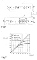
Figure 2 is a graph of the estimated signal-to-noise ratio SNRs versus the exact value SNRe of an SNR estimator in accordance with the known art; -
Figure 3 is a graph of the mean square error MSE versus the exact value of the signal-to-noise ratio SNRe of the estimator in accordance with the known art; -
Figure 4 is a graph of the estimated signal-to-noise ratio SNRs versus the exact value SNRe of the SNR estimator in accordance with the first embodiment ; -
Figure 5 is a graph of the mean square error MSE versus the value of the signal-to-noise ratio SNRe of the estimator in accordance with the first embodiment ; -
Figure 6 is a graph of the estimated signal-to-noise ratio SNRs versus the exact value SNRe of the SNR estimator in accordance with the first and second embodiments for some combinations of B and L; -
Figure 7 is a graph of the mean square error MSE versus the value of the signal-to-noise ratio SNRe of the SNR estimator in accordance with the first and second embodiments for some combinations of B and L; -
Figure 8 is a graph of the estimated signal-to-noise ratio SNRs versus the exact value SNRe of the SNR estimator in accordance with the fourth embodiment for some combinations of B and L and O; -
Figure 9 is a graph of the mean square error MSE versus the value of the signal-to-noise ratio SNRe of the SNR estimator in accordance with the fourth embodiment for some combinations of B and L and O; -
Figure 10 is the equivalent base-band scheme of a pass-band packet transmission and reception multiple carrier system with M-DPSK modulator and demodulator and apparatus for estimating the signal-to-noise ratio in accordance with the present invention; -
Figure 11 is a graph of the estimated signal-to-noise ratio SNRs versus the exact value SNRe of the SNR estimator in accordance with the second embodiment for a multiple carrier transmission and reception system; -
Figure 12 is a graph of the mean square error MSE versus the value of the signal-to-noise ratio SNRe of the SNR estimator in accordance with the second embodiment for a multiple carrier transmission and reception system. -
Figure 1 shows the equivalent base-band scheme of a pass-band packet transmission and reception system of signals with a single carrier. The M-DPSK modulator 1 comprises an M-PSK bit mapper 2 where M is the modulation order, i.e. the number of possible constellation symbols. The mapper comprises a serial-to-parallel converter followed by a map transforming a sequence of log2 M bit ci into corresponding constellation points with values

PSK mapper 2 and thedifferential block 3, the phase δ k associated with the symbol transmitted at the kT instant is the same as the phase transmitted at the preceding instant (k-1)T, i.e. δ k-1, with a phase increase ϕ k which may assume one of the M values belonging to the range [0, 2π/M,...2π(M-1)lM]. Therefore, in the M-PSK bit mapper, the phase transmitted at the kT instant is given by: δ k = δ k-1 + ϕ k . The modulated symbol at the output of thedifferential block 3 is ak = e jδ k . The receiver retrieves the transmitted data using the phase difference between consecutive samples without needing to retrieve the phase offset introduced by the channel and the phase offset between transmitter and receiver on the carrier frequency. - The symbol ak is associated with a limited-band hT (t)
filter 4 so that at the output offilter 4 there is the signal
transmission channel 5. Assuming that thetransmission channel 5 is a channel which is flat on the signal band and time-invariant with a constant gain gch (t) = G, the signal at the output of thechannel 5 still has a PSK structure; noise is added to the signal s(t), preferably an additive white Gaussian noise w(t) (AWGN) having a null average with double-sided spectral power density of N0/2. - Indicating the convolution by the symbol ⊗, and the frequency and phase offset on the carrier frequency between the transmitter and the receiver by Δf and Δϑ, the signal x(t) at the output of the
channel 5 and at the input of thereceiver 6 is given by:

- Assuming that the frequency offset Δf is sufficiently small and considering the
filter 6 of the receiver with a function hR (t) at the output of the filter, the following equation is given
where
- At the sampling instant kT + t0 where t0 is the sampling phase the following equation is given

where
- Assuming that the function hk = h(kT + t 0) satisfies the Nyquist condition:


where
- The sampled signal rk is processed by a M-DPSK
differential demodulator module 7 and sent to an invertedbit mapper 8 providing decisions on the received bits q i. - The demodulator multiplies the sampled signal rk by its delayed and conjugated version


where the normalized frequency offset is defined as Δfn = Δf · T. As seen from the preceding formula, the useful term i.e. theterm 
- The disadvantage of such a differential demodulator is due to the fact that the term bonded to the noise is amplified. In order to avoid said disadvantage, the SNR estimators considered in this invention act on the signal r(t) at the input of the M-
DPSK block 7 of the receiver. - Considering an N sequence of samples rk consecutively received and l as the index denoting the position of the first known symbol of the sequence in the packet, assuming the channel gain G to be constant over the N samples and the number N to be sufficiently great so as to average out the noise out, assumed as a null average, and knowing that |ak |2 = 1 for unitary power PSK constellations, the following equation is given:

where the values Ĝ and


- The estimation of the signal-to-noise ratio SNR is determined by:

- In the presence of frequency offsets Δfn , when the condition Δfnl ≅ Δfn (l + N -1) is no longer true and therefore the approximation

Figures 2 and3 relating to the estimated signal-to-noise ratio SNRs versus the exact value SNRe over various values of Δfn and to the mean square error MSE against the value SNRe over various values of Δfn , respectively. As the frequency offset Δfn increases, the MSE error is noted to dramatically increase and the values of SNRs diverge from SNRe. In accordance with the invention, the N known symbols ak and the N samples rk consecutively received and corresponding to the known symbols ak are divided into B blocks of length L, N = B·L, i.e. the known sequence N of the data packet and the N received samples now consist of B blocks of length L, with B greater than one; specifically,estimator 100 comprises adivider module 101 allowing the N known symbols ak and the N samples rk consecutively received and corresponding to the known symbols ak to be converted into B blocks of length L. The following equation is given:
where lb = L·b+l. Assuming the channel gain G to be constant over the L samples and the number L to be sufficiently great, grater than 8, so as to allow the noise, assumed as a null average, to be averaged out, and the condition Δfnlb ≅ Δfn (lb + L-1) to be satisfied, the following approximation may be carried out:
- The
SNR estimator 100 comprises ablock 102 allowing the signal-to noise ratio to be calculated by means of the following equation:
-
Figure 4 shows a graph of the estimated signal-to noise ratio SNRs versus the exact value SNRe over values of Δfn being 10-3 and 2·10-3 with B = 2 and L = 16 of theSNR estimator 100, indicated as SNVS(B, L), whereasFigure 5 shows a graph of the mean square error MSE against the value SNRe over values of Δfn being 10-3 and 2·10-3 with B = 2 and L = 16 of the SNR estimator; both graphs show the estimator in accordance with the known art for Δfn = 0, indicated as BOUND. From the values ofFigures 2 ,3 andFigures 4 ,5 , the improvement of the performances of the SNR estimator is apparent as compared to the estimator in accordance with the known art. - In accordance with a second embodiment, assuming similarly to the first embodiment the channel gain G to be constant over the L samples and the condition Δfnlb ≅ Δfn (lb + L -1) to be satisfied, and assuming the number L, differently from the first embodiment, not to be sufficiently great to average the noise out and always with B > 1, the following approximation may be carried out:


- The SNR ratio comprises a weighting factor 1-1/L to weight the signal-to-noise ratio and a corrective term -1/L, it is noted that, if L is sufficiently great, the weighting factor (1-1/L) and the corrective term -1/L may be ignored, thus recovering the equation of the first embodiment of the estimator. In some cases, the corrective term -1/L alone may be ignored.
- From the equations relating to the signal-to-noise ratio SNR of the first and second embodiments, it is apparent that for greater values of B the estimator is stronger with respect to the frequency offsets whereas for low values of L the estimator is more sensitive to the noise.
-
Figure 6 shows a graph of the estimated signal-to noise ratio SNRs versus the exact value SNRe over values of Δfn being 2·10-3 with values of B being 2, 4, 8 and respective values of L being 16, 8, 4 of the SNR estimator in accordance with the first and second embodiments, whereasFigure 7 shows a graph of the mean square error MSE versus the value SNRe over values of Δfn being 2·10-3 with values of B being 2, 4, 8 and respective values of L being 16, 8, 4 of theSNR estimator 100 in accordance with the first and second embodiments; the estimator in accordance with the first embodiment is indicated as SNVS (B, L), whereas that in accordance with the second embodiment is indicated as RSNVS(B, L). From the values ofFigures 6 and7 , the improvement of the RSNVS estimator performances is apparent as compared to the SNVS with low values of L. - In accordance with a third embodiment, the
block 101 of theSNR estimator 100, in addition to the division N = B·L, also allows to overlap consecutive blocks having a length L of a factor O always with B > 1. Given a known sequence having a length N, the number of possible divisions is given by
SNR estimator 100 in accordance with the third embodiment allows the signal-to-noise ratio to be calculated with theblock 102 by means of the following equation:
- In accordance with a fourth embodiment, considered as a variant of the third embodiment, the
block 102 of theestimator 100 comprises, similarly to the second embodiment, a weighting factor 1-1/L to weigh the signal-to-noise ratio and a corrective term -1/L such that the calculation of the signal-to-noise ratio is performed by means of the following equation:
- It is noted that, similarly to the second embodiment, if L is sufficiently great, the weighting factor (1-1/L) and the corrective term -1/L may be ignored, thus recovering the equation of the third embodiment of the estimator. In some cases, the corrective term -1/L alone may be ignored.
- Once N has been fixed, more combinations of B and L may be obtained with good performances, as shown in
Figures 8 and9 where there are shown a graph of the estimated signal-to-noise ratio SNRs versus the exact value SNRe over values of Δfn being 2·10-3 with values of B being 4, 6, 8, 10, 14 and L being 4, 5, 6, 7, 8 and O being 2, 4 of the SNR estimator in accordance with the second and fourth embodiments, and a graph of the mean square error MSE versus the value SNRe over values of Δfn being 2·10-3 with values of B being 4, 6, 8, 10, 14 and L being 4, 5, 6, 7, 8 and O being 2, 4 of the SNR estimator in accordance with the second and fourth embodiments, respectively, the estimator in accordance with the second embodiment is indicated as RSNVS(B, L) whereas the estimator in accordance with the fourth embodiment is indicated as RSNVSO(O, B, L). - The means 101 and 102 of the
estimator 100 preferably comprise a microprocessor and a memory on which an application software is running thus allowing the division N = B·L and preferably also the overlapping of consecutive blocks having a length L of a factor O as previously specified and the execution of the calculation of the signal-to-noise ratio according to any one of the preceding equations. - The
SNR estimator 100 in accordance with the preceding embodiments may also be used for multiple carrier systems, such as the OFDM (Orthogonal Frequency Division Multiplexing) systems. In these transmission systems, there are multiple phenomena that may cause a progressive phase shifting of the received constellation, resulting in effects which are completely similar to the carrier frequency offset in the single carrier systems. It is for this reason that using the estimator in accordance with the invention may also be useful in multiple carrier systems, specifically at the input of the differential demodulator, rather than the estimator in accordance with the known art. The phenomena responsible for the progressive phase shifting of the received constellation include: the carrier frequency offset, the packet synchronization offset and the sampling frequency offset. Each of these phenomena produces a different effect over the various subcarriers of the system and on the OFDM various symbols forming the transmitted packet. For example, the carrier frequency offset, in a pass-band system, produces a phase shifting of the constellation being constant on all the subcarriers of an OFDM symbol but increasing over time for every received OFDM symbol. On the other hand, the packet synchronization offset produces a rotation proportional to the subcarrier index, however remaining constant over all the symbols of the packet. Finally, the sampling frequency offset produces a rotation of the received constellation being different according to both the subcarrier index and the received OFDM symbol. - Given the complexity of the phenomenon, in an OFDM system, a "data aided" SNR estimator may be implemented in different ways, based on the negative effect to be minimized. Specifically, an SNR estimator may act on the frequency in the various carriers or over time between the different transmitted OFDM symbols. However, in any case, the known transmitted sequence of length N and the N received samples may be divided in accordance with the invention in order to reduce the negative effect of the rotation of the constellation in estimating the value of SNR. By way of non-limiting example, we refer to a pass-band OFDM system where every subcarrier is M-DPSK modulated, i.e. the differential is achieved over time, and no recovery of the carrier frequency is achieved during the reception; an OFDM system in accordance with the invention is shown in
Figure 10 . The M-PSK modulator 200 comprises a serial-to-parallel converter followed by a map which transforms a sequence of log2 M bit ci into corresponding constellation points,
PSK mapper 200 is followed by a serial-to-parallel converter 201 having NFFT outputs with values of
FFT-1 , being
block 203 to carry out the inverse Fourier transform of said signals and ablock 204 for the parallel-to-serial conversion of the signals. The obtained signals are at the input of achannel 205 with a transfer function G(f). - The OFDM systems allow the signal band to be divided into sub-bands in which the transfer function of the channel G(f) may be approximated as almost flat. Under these conditions, the estimator in accordance with the present invention may independently be applied to every OFDM subcarrier. Once the noise w(t) has been added, the passage through the serial-to-
parallel converter 206 and the block for applying theFourier transform 207, in the presence of an offset between the carrier frequency of the transmitter and receiver, the sample relating to the nth symbol and the hth subcarrier has the following expression:
where an,k and Gk are the transmitted M-DPSK symbol and the complex coefficient of the channel gain on the kth subcarrier, respectively, Wn,h represents the noise after the discrete Fourier transform (DFT), NFFT is the number of subcarriers, F=1/T is the sampling frequency and the function
- The preceding relation may be written as:

where
SNR estimators 100 more sensitive to the frequency offset as compared to single carrier transmission and reception systems. The frequency offset determines a phase rotation for the received symbols being constant over all the subcarriers, said phase rotation is proportional to the normalized frequency offset Δfn with respect to the sampling frequency F, Δ fn = Δf / F = Δf · T. The samples rn,0 ... r n,NFFT-1 are at the input of theSNR estimators 100 and then at the input of the M-DPSK receivers 208, parallel-to-serial converter 209,inverted mapper 210 in order to have the estimated bits mi corresponding to the bits ci at the output. - It is noted that the SNR estimator is applied at the input of the differential demodulator: if the SNR estimator is applied at the output of the differential demodulator there is a greater insensitivity to the frequency offset, the disadvantage being the noise amplification.
- In the graphs of
Figures 11 and12 , there are shown the estimated signal-to-noise ratio SNRs versus the exact value SNRe over values of Δfn being 10-4 and 5·10-5 of the SNR estimator for a single carrier in accordance with the known art and the second embodiment being B = 4 and L = 8 and the mean square error MSE versus the value SNRe over values of Δfn being 10-4 and 5·10-5 of the SNR estimator in accordance with the known art and the second embodiment being B = 4 and L = 8, respectively; the estimator in accordance with the known art is indicated as SNV whereas the estimator in accordance with the second embodiment is indicated as RSNVS(B, L). Both graphs show the estimator in accordance with the known art for Δfn = 0, indicated as BOUND. - From the values of
Figures 11 and12 , the improvement of the RSNVS estimator performances is apparent as compared to the SNV estimator. - The used pass-band single carrier communication system preferably works at a carrier frequency of 100 kHz and has a system clock having a tolerance of ± 200 ppm or ± 100 ppm and a sampling frequency being F = 10 kHz with the SNR estimator applied at the input of the differential demodulator.
- The used pass-band multiple carrier communication system preferably works at a carrier frequency of 250 kHz and has a system clock having a tolerance of ± 40 ppm or ± 20 ppm and a sampling frequency being F = 100 kHz with the SNR estimator applied at the input of the differential demodulator.
Claims (11)
- Method for estimating the signal-to-noise ratio for a packet transmission and reception system of signals having a known data sequence by means of a M-DPSK modulation with at least one carrier, said system comprising means for packet transmission of a signal with a sequence of N known symbols, with N positive integer number, said transmission comprising a M-DPSK modulation (1) of the signal to transmit by means of a M-PSK mapper (2) and a differential block (3), the transmission of the M-DPSK modulated signal (s(t)) through a channel (5) having constant gain over all the N symbols and in presence of noise (w(t)) with null average, and the reception of the signal (r(t)) at the output of the channel,
wherein said method comprises the estimation of the signal-to-noise ratio of the received signal with the division of the N known symbols and of N samples of the signal (r(t)) at the output of the channel into B blocks of L length with B and L positive integer numbers and B greater than one and wherein B is expressed by

index denoting the position of the first known symbol of the sequence of length N in the packet, rk is the sample of the received signal at the output of the channel correspondent to the known transmitted symbol, ak is the M-DPSK modulated known transmitted symbol,
- Method according to claim 1, characterized in that when O = 0 the B blocks are expressed by


- Method according to claim 1, characterized in that if the length L of the blocks B is sufficiently great to average the noise, said estimation of the signal-to-noise ratio is given by:

- Method according to claim 1, characterized in that said transmission and reception system is of the pass-band type and the reception is of the non-coherent type with differential demodulation, said estimation of the signal-to-noise ratio being effectuated before the differential demodulation of the signal.
- Method according to any one of the preceding claims, characterized in that said transmission and reception system is of the multiple carrier type.
- Apparatus for estimating the signal-to-noise ratio for use in a packet transmission and reception system of signals having a known data sequence by means of a M-DPSK modulation with at least one carrier, said system comprising means for the packet transmission of a signal with a sequence of N known symbols, with N positive integer number, said transmission means comprising a M-DPSK modulator (1) of the signal to transmit comprising a M-PSK mapper (2) and a differential block (3), the M-DPSK modulated signal (s(t)) being adapted to pass through a channel (5) having constant gain over all the N symbols and in presence of noise (w(t)) with null average, said system comprising means (10) for receiving the signal (r(t)) at the output of the channel,
said apparatus comprising first means (101) adapted to divide the N known symbols and N samples of the signal (r(t)) at the output of the channel into B blocks of L length with B and L positive integer numbers and B greater than one and said first means (101) being adapted to overlap consecutive blocks having length L of a factor O, B being expressed by


- Apparatus according to claim 6, characterized in that O = 0 and said second means (102) are adapted to effectuate the estimation of the signal-to-noise ratio by the equation:

- Apparatus according to claim 6, characterized in that if the length L of the blocks B is sufficiently great to average the noise said second means (102) are adapted to calculate the estimation of the signal-to-noise ratio by the equation:

- Apparatus according to claim 6, characterized in that said transmission and reception system is of the pass-band type, said reception means (10) of the signal effectuating a non-coherent reception and comprising a differential demodulator (7), said estimation apparatus being adapted to calculate the estimation of the signal-to-noise ratio of the signal at the input of the differential demodulator.
- Apparatus according to any one of the claims from 6 to 9, characterized in that said transmission and reception system is of the multiple carrier type.
- Packet transmission and reception system of signals having a known data sequence by means of a M-DPSK modulation with at least one carrier,
said system comprising means for the packet transmission of a signal with a sequence of N known symbols, with N positive integer number, said transmission means comprising a M-DPSK modulator (1) of the signal to transmit comprising a M-PSK mapper (2) and a differential block (3), the M-DPSK modulated signal (s(t)) being adapted to pass through a channel (5) having constant gain over all the N symbols and in presence of noise (w(t)) with null average,
said system comprising means (10) for receiving the signal (r(t)) at the output of the channel which comprises a differential demodulator (7) and an apparatus as defined in any one of claims from 6 to 10 adapted to effectuate the estimation of the signal-to-noise ratio of the signal at the input of said differential demodulator (7).
Applications Claiming Priority (1)
| Application Number | Priority Date | Filing Date | Title |
|---|---|---|---|
| ITMI20082304 | 2008-12-23 |
Publications (2)
| Publication Number | Publication Date |
|---|---|
| EP2202906A1 EP2202906A1 (en) | 2010-06-30 |
| EP2202906B1 true EP2202906B1 (en) | 2015-05-20 |
Family
ID=41227241
Family Applications (1)
| Application Number | Title | Priority Date | Filing Date |
|---|---|---|---|
| EP20090180214 Active EP2202906B1 (en) | 2008-12-23 | 2009-12-21 | Data-aided signal-to-noise ratio estimate for M-DPSK modulation systems with division of the received samples into blocks |
Country Status (2)
| Country | Link |
|---|---|
| US (1) | US8363760B2 (en) |
| EP (1) | EP2202906B1 (en) |
Families Citing this family (3)
| Publication number | Priority date | Publication date | Assignee | Title |
|---|---|---|---|---|
| US8265203B2 (en) * | 2009-01-21 | 2012-09-11 | Ntt Docomo, Inc. | Method and system of differential complex and real multi-carrier demodulation |
| EP2280510B1 (en) * | 2009-07-09 | 2016-05-04 | STMicroelectronics S.r.l. | Method of detecting a frame synchronization pattern or a unique word in a received digital signal |
| WO2018074393A1 (en) * | 2016-10-19 | 2018-04-26 | 日本電気株式会社 | Communication device, communication system, and communication method |
Family Cites Families (3)
| Publication number | Priority date | Publication date | Assignee | Title |
|---|---|---|---|---|
| US7356071B2 (en) * | 2005-05-06 | 2008-04-08 | Interdigital Technology Corporation | Method and apparatus for estimating signal-to-noise ratio based on dedicated physical channel pilot symbols |
| US20070002980A1 (en) * | 2005-06-29 | 2007-01-04 | Eyal Krupka | Method for timing and sequence hypotheses selection |
| KR100930720B1 (en) * | 2007-11-29 | 2009-12-09 | 한국전자통신연구원 | Signal to Noise Ratio Estimation Apparatus and Method |
-
2009
- 2009-12-21 EP EP20090180214 patent/EP2202906B1/en active Active
- 2009-12-23 US US12/646,348 patent/US8363760B2/en active Active
Also Published As
| Publication number | Publication date |
|---|---|
| EP2202906A1 (en) | 2010-06-30 |
| US20100166101A1 (en) | 2010-07-01 |
| US8363760B2 (en) | 2013-01-29 |
Similar Documents
| Publication | Publication Date | Title |
|---|---|---|
| EP1028564B1 (en) | Estimation of carrier and sampling frequency offsets in multicarrier receivers | |
| CN100591064C (en) | Sampling frequency offset estimation apparatus and method for OFDM system | |
| US7308034B2 (en) | Method and device for tracking carrier frequency offset and sampling frequency offset in orthogonal frequency division multiplexing wireless communication system | |
| US7489731B2 (en) | Communication system using OFDM | |
| Armstrong | Analysis of new and existing methods of reducing intercarrier interference due to carrier frequency offset in OFDM | |
| US6487252B1 (en) | Wireless communication system and method for synchronization | |
| EP1894378B1 (en) | Receiver apparatus for receiving a multicarrier signal | |
| US7139321B2 (en) | Channel estimation for wireless OFDM systems | |
| EP1072138B1 (en) | Method and apparatus for fine frequency synchronization in multi-carrier demodulation systems | |
| US20040120412A1 (en) | Carrier frequency offset estimation in a wireless communication system | |
| US7684501B2 (en) | Apparatus and method for carrier frequency offset and phase compensation in communication system | |
| EP1924045B1 (en) | OFDM with bandwidth limitation | |
| US20040032909A1 (en) | Reference symbol multicarrier signal designed to limit intersymbol interference | |
| US8433014B2 (en) | Receiving apparatus and receiving method | |
| US8509331B2 (en) | Method for the blind estimation of OFDM modulation parameters according to a maximum likelihood criterion | |
| EP2202906B1 (en) | Data-aided signal-to-noise ratio estimate for M-DPSK modulation systems with division of the received samples into blocks | |
| US8379780B2 (en) | Method for compensation of information losses in an OFDM-based multi-carrier communication signal caused by blanking out pulse-shaped interferences | |
| US8743946B2 (en) | Frequency-domain equalization and combining for single carrier transmission | |
| US7579921B2 (en) | On-off keying-7-phase shift keying modulation system and method for fiber communication | |
| CN109688081A (en) | A kind of signal frequency deviation estimation method based on II standard of TETRA, wireless communication system | |
| US7515657B1 (en) | Frequency tracking for OFDM transmission over frequency selective channels | |
| KR100429837B1 (en) | Method and apparatus for synchronization of OFDM signals | |
| US8223865B2 (en) | Method for the blind estimation of OFDM signal parameters by adapted filtering | |
| WO2008082117A1 (en) | Method and apparatus for estimating carrier to interference and noise ratio | |
| KR20030016751A (en) | Signal to noise ratio estimation apparatus and method using frequency component information |
Legal Events
| Date | Code | Title | Description |
|---|---|---|---|
| PUAI | Public reference made under article 153(3) epc to a published international application that has entered the european phase |
Free format text: ORIGINAL CODE: 0009012 |
|
| AK | Designated contracting states |
Kind code of ref document: A1 Designated state(s): AT BE BG CH CY CZ DE DK EE ES FI FR GB GR HR HU IE IS IT LI LT LU LV MC MK MT NL NO PL PT RO SE SI SK SM TR |
|
| 17P | Request for examination filed |
Effective date: 20101210 |
|
| GRAP | Despatch of communication of intention to grant a patent |
Free format text: ORIGINAL CODE: EPIDOSNIGR1 |
|
| RIC1 | Information provided on ipc code assigned before grant |
Ipc: H04L 1/20 20060101AFI20141117BHEP Ipc: H04B 17/00 20060101ALI20141117BHEP Ipc: H04L 27/233 20060101ALI20141117BHEP |
|
| INTG | Intention to grant announced |
Effective date: 20141211 |
|
| GRAS | Grant fee paid |
Free format text: ORIGINAL CODE: EPIDOSNIGR3 |
|
| GRAA | (expected) grant |
Free format text: ORIGINAL CODE: 0009210 |
|
| AK | Designated contracting states |
Kind code of ref document: B1 Designated state(s): AT BE BG CH CY CZ DE DK EE ES FI FR GB GR HR HU IE IS IT LI LT LU LV MC MK MT NL NO PL PT RO SE SI SK SM TR |
|
| RAP1 | Party data changed (applicant data changed or rights of an application transferred) |
Owner name: STMICROELECTRONICS S.R.L. |
|
| REG | Reference to a national code |
Ref country code: GB Ref legal event code: FG4D |
|
| REG | Reference to a national code |
Ref country code: CH Ref legal event code: EP |
|
| REG | Reference to a national code |
Ref country code: AT Ref legal event code: REF Ref document number: 728217 Country of ref document: AT Kind code of ref document: T Effective date: 20150615 |
|
| REG | Reference to a national code |
Ref country code: IE Ref legal event code: FG4D |
|
| REG | Reference to a national code |
Ref country code: DE Ref legal event code: R096 Ref document number: 602009031295 Country of ref document: DE |
|
| REG | Reference to a national code |
Ref country code: AT Ref legal event code: MK05 Ref document number: 728217 Country of ref document: AT Kind code of ref document: T Effective date: 20150520 |
|
| REG | Reference to a national code |
Ref country code: LT Ref legal event code: MG4D |
|
| REG | Reference to a national code |
Ref country code: NL Ref legal event code: MP Effective date: 20150520 |
|
| PG25 | Lapsed in a contracting state [announced via postgrant information from national office to epo] |
Ref country code: ES Free format text: LAPSE BECAUSE OF FAILURE TO SUBMIT A TRANSLATION OF THE DESCRIPTION OR TO PAY THE FEE WITHIN THE PRESCRIBED TIME-LIMIT Effective date: 20150520 Ref country code: PT Free format text: LAPSE BECAUSE OF FAILURE TO SUBMIT A TRANSLATION OF THE DESCRIPTION OR TO PAY THE FEE WITHIN THE PRESCRIBED TIME-LIMIT Effective date: 20150921 Ref country code: LT Free format text: LAPSE BECAUSE OF FAILURE TO SUBMIT A TRANSLATION OF THE DESCRIPTION OR TO PAY THE FEE WITHIN THE PRESCRIBED TIME-LIMIT Effective date: 20150520 Ref country code: NO Free format text: LAPSE BECAUSE OF FAILURE TO SUBMIT A TRANSLATION OF THE DESCRIPTION OR TO PAY THE FEE WITHIN THE PRESCRIBED TIME-LIMIT Effective date: 20150820 Ref country code: HR Free format text: LAPSE BECAUSE OF FAILURE TO SUBMIT A TRANSLATION OF THE DESCRIPTION OR TO PAY THE FEE WITHIN THE PRESCRIBED TIME-LIMIT Effective date: 20150520 Ref country code: FI Free format text: LAPSE BECAUSE OF FAILURE TO SUBMIT A TRANSLATION OF THE DESCRIPTION OR TO PAY THE FEE WITHIN THE PRESCRIBED TIME-LIMIT Effective date: 20150520 |
|
| PG25 | Lapsed in a contracting state [announced via postgrant information from national office to epo] |
Ref country code: IS Free format text: LAPSE BECAUSE OF FAILURE TO SUBMIT A TRANSLATION OF THE DESCRIPTION OR TO PAY THE FEE WITHIN THE PRESCRIBED TIME-LIMIT Effective date: 20150920 Ref country code: BG Free format text: LAPSE BECAUSE OF FAILURE TO SUBMIT A TRANSLATION OF THE DESCRIPTION OR TO PAY THE FEE WITHIN THE PRESCRIBED TIME-LIMIT Effective date: 20150820 Ref country code: AT Free format text: LAPSE BECAUSE OF FAILURE TO SUBMIT A TRANSLATION OF THE DESCRIPTION OR TO PAY THE FEE WITHIN THE PRESCRIBED TIME-LIMIT Effective date: 20150520 Ref country code: GR Free format text: LAPSE BECAUSE OF FAILURE TO SUBMIT A TRANSLATION OF THE DESCRIPTION OR TO PAY THE FEE WITHIN THE PRESCRIBED TIME-LIMIT Effective date: 20150821 Ref country code: LV Free format text: LAPSE BECAUSE OF FAILURE TO SUBMIT A TRANSLATION OF THE DESCRIPTION OR TO PAY THE FEE WITHIN THE PRESCRIBED TIME-LIMIT Effective date: 20150520 |
|
| PG25 | Lapsed in a contracting state [announced via postgrant information from national office to epo] |
Ref country code: DK Free format text: LAPSE BECAUSE OF FAILURE TO SUBMIT A TRANSLATION OF THE DESCRIPTION OR TO PAY THE FEE WITHIN THE PRESCRIBED TIME-LIMIT Effective date: 20150520 Ref country code: EE Free format text: LAPSE BECAUSE OF FAILURE TO SUBMIT A TRANSLATION OF THE DESCRIPTION OR TO PAY THE FEE WITHIN THE PRESCRIBED TIME-LIMIT Effective date: 20150520 |
|
| REG | Reference to a national code |
Ref country code: DE Ref legal event code: R097 Ref document number: 602009031295 Country of ref document: DE |
|
| PG25 | Lapsed in a contracting state [announced via postgrant information from national office to epo] |
Ref country code: SK Free format text: LAPSE BECAUSE OF FAILURE TO SUBMIT A TRANSLATION OF THE DESCRIPTION OR TO PAY THE FEE WITHIN THE PRESCRIBED TIME-LIMIT Effective date: 20150520 Ref country code: CZ Free format text: LAPSE BECAUSE OF FAILURE TO SUBMIT A TRANSLATION OF THE DESCRIPTION OR TO PAY THE FEE WITHIN THE PRESCRIBED TIME-LIMIT Effective date: 20150520 Ref country code: RO Free format text: LAPSE BECAUSE OF NON-PAYMENT OF DUE FEES Effective date: 20150520 Ref country code: PL Free format text: LAPSE BECAUSE OF FAILURE TO SUBMIT A TRANSLATION OF THE DESCRIPTION OR TO PAY THE FEE WITHIN THE PRESCRIBED TIME-LIMIT Effective date: 20150520 |
|
| PLBE | No opposition filed within time limit |
Free format text: ORIGINAL CODE: 0009261 |
|
| STAA | Information on the status of an ep patent application or granted ep patent |
Free format text: STATUS: NO OPPOSITION FILED WITHIN TIME LIMIT |
|
| 26N | No opposition filed |
Effective date: 20160223 |
|
| PG25 | Lapsed in a contracting state [announced via postgrant information from national office to epo] |
Ref country code: BE Free format text: LAPSE BECAUSE OF NON-PAYMENT OF DUE FEES Effective date: 20151231 Ref country code: SI Free format text: LAPSE BECAUSE OF FAILURE TO SUBMIT A TRANSLATION OF THE DESCRIPTION OR TO PAY THE FEE WITHIN THE PRESCRIBED TIME-LIMIT Effective date: 20150520 |
|
| PG25 | Lapsed in a contracting state [announced via postgrant information from national office to epo] |
Ref country code: LU Free format text: LAPSE BECAUSE OF FAILURE TO SUBMIT A TRANSLATION OF THE DESCRIPTION OR TO PAY THE FEE WITHIN THE PRESCRIBED TIME-LIMIT Effective date: 20151221 Ref country code: MC Free format text: LAPSE BECAUSE OF FAILURE TO SUBMIT A TRANSLATION OF THE DESCRIPTION OR TO PAY THE FEE WITHIN THE PRESCRIBED TIME-LIMIT Effective date: 20150520 |
|
| REG | Reference to a national code |
Ref country code: CH Ref legal event code: PL |
|
| GBPC | Gb: european patent ceased through non-payment of renewal fee |
Effective date: 20151221 |
|
| PG25 | Lapsed in a contracting state [announced via postgrant information from national office to epo] |
Ref country code: BE Free format text: LAPSE BECAUSE OF FAILURE TO SUBMIT A TRANSLATION OF THE DESCRIPTION OR TO PAY THE FEE WITHIN THE PRESCRIBED TIME-LIMIT Effective date: 20150520 |
|
| REG | Reference to a national code |
Ref country code: IE Ref legal event code: MM4A |
|
| REG | Reference to a national code |
Ref country code: FR Ref legal event code: ST Effective date: 20160831 |
|
| PG25 | Lapsed in a contracting state [announced via postgrant information from national office to epo] |
Ref country code: CH Free format text: LAPSE BECAUSE OF NON-PAYMENT OF DUE FEES Effective date: 20151231 Ref country code: GB Free format text: LAPSE BECAUSE OF NON-PAYMENT OF DUE FEES Effective date: 20151221 Ref country code: LI Free format text: LAPSE BECAUSE OF NON-PAYMENT OF DUE FEES Effective date: 20151231 Ref country code: IE Free format text: LAPSE BECAUSE OF NON-PAYMENT OF DUE FEES Effective date: 20151221 |
|
| PG25 | Lapsed in a contracting state [announced via postgrant information from national office to epo] |
Ref country code: FR Free format text: LAPSE BECAUSE OF NON-PAYMENT OF DUE FEES Effective date: 20151231 |
|
| PG25 | Lapsed in a contracting state [announced via postgrant information from national office to epo] |
Ref country code: HU Free format text: LAPSE BECAUSE OF FAILURE TO SUBMIT A TRANSLATION OF THE DESCRIPTION OR TO PAY THE FEE WITHIN THE PRESCRIBED TIME-LIMIT; INVALID AB INITIO Effective date: 20091221 Ref country code: SM Free format text: LAPSE BECAUSE OF FAILURE TO SUBMIT A TRANSLATION OF THE DESCRIPTION OR TO PAY THE FEE WITHIN THE PRESCRIBED TIME-LIMIT Effective date: 20150520 |
|
| PG25 | Lapsed in a contracting state [announced via postgrant information from national office to epo] |
Ref country code: SE Free format text: LAPSE BECAUSE OF FAILURE TO SUBMIT A TRANSLATION OF THE DESCRIPTION OR TO PAY THE FEE WITHIN THE PRESCRIBED TIME-LIMIT Effective date: 20150520 Ref country code: CY Free format text: LAPSE BECAUSE OF FAILURE TO SUBMIT A TRANSLATION OF THE DESCRIPTION OR TO PAY THE FEE WITHIN THE PRESCRIBED TIME-LIMIT Effective date: 20150520 Ref country code: NL Free format text: LAPSE BECAUSE OF FAILURE TO SUBMIT A TRANSLATION OF THE DESCRIPTION OR TO PAY THE FEE WITHIN THE PRESCRIBED TIME-LIMIT Effective date: 20150520 |
|
| PG25 | Lapsed in a contracting state [announced via postgrant information from national office to epo] |
Ref country code: TR Free format text: LAPSE BECAUSE OF FAILURE TO SUBMIT A TRANSLATION OF THE DESCRIPTION OR TO PAY THE FEE WITHIN THE PRESCRIBED TIME-LIMIT Effective date: 20150520 Ref country code: MT Free format text: LAPSE BECAUSE OF FAILURE TO SUBMIT A TRANSLATION OF THE DESCRIPTION OR TO PAY THE FEE WITHIN THE PRESCRIBED TIME-LIMIT Effective date: 20150520 |
|
| PG25 | Lapsed in a contracting state [announced via postgrant information from national office to epo] |
Ref country code: MK Free format text: LAPSE BECAUSE OF FAILURE TO SUBMIT A TRANSLATION OF THE DESCRIPTION OR TO PAY THE FEE WITHIN THE PRESCRIBED TIME-LIMIT Effective date: 20150520 |
|
| PGFP | Annual fee paid to national office [announced via postgrant information from national office to epo] |
Ref country code: IT Payment date: 20221122 Year of fee payment: 14 |
|
| PGFP | Annual fee paid to national office [announced via postgrant information from national office to epo] |
Ref country code: DE Payment date: 20231121 Year of fee payment: 15 |