EP2197612B2 - Drilling tool with drill bit - Google Patents
Drilling tool with drill bit Download PDFInfo
- Publication number
- EP2197612B2 EP2197612B2 EP08786180.3A EP08786180A EP2197612B2 EP 2197612 B2 EP2197612 B2 EP 2197612B2 EP 08786180 A EP08786180 A EP 08786180A EP 2197612 B2 EP2197612 B2 EP 2197612B2
- Authority
- EP
- European Patent Office
- Prior art keywords
- coupling
- rotation
- drilling tool
- receptacle
- drill bit
- Prior art date
- Legal status (The legal status is an assumption and is not a legal conclusion. Google has not performed a legal analysis and makes no representation as to the accuracy of the status listed.)
- Active
Links
- 238000005553 drilling Methods 0.000 title claims abstract description 28
- 230000008878 coupling Effects 0.000 claims abstract description 80
- 238000010168 coupling process Methods 0.000 claims abstract description 80
- 238000005859 coupling reaction Methods 0.000 claims abstract description 80
- 230000000295 complement effect Effects 0.000 claims abstract description 14
- 238000000926 separation method Methods 0.000 claims description 7
- 230000001154 acute effect Effects 0.000 claims description 4
- 239000002826 coolant Substances 0.000 claims description 3
- 239000000463 material Substances 0.000 description 3
- 229910001315 Tool steel Inorganic materials 0.000 description 2
- 230000000694 effects Effects 0.000 description 2
- 238000004519 manufacturing process Methods 0.000 description 2
- 238000000034 method Methods 0.000 description 2
- RYGMFSIKBFXOCR-UHFFFAOYSA-N Copper Chemical compound [Cu] RYGMFSIKBFXOCR-UHFFFAOYSA-N 0.000 description 1
- 229910000997 High-speed steel Inorganic materials 0.000 description 1
- 239000000919 ceramic Substances 0.000 description 1
- 229910052802 copper Inorganic materials 0.000 description 1
- 239000010949 copper Substances 0.000 description 1
- 230000003247 decreasing effect Effects 0.000 description 1
- 230000001419 dependent effect Effects 0.000 description 1
- 238000011161 development Methods 0.000 description 1
- 230000018109 developmental process Effects 0.000 description 1
- 238000010586 diagram Methods 0.000 description 1
- 238000002347 injection Methods 0.000 description 1
- 239000007924 injection Substances 0.000 description 1
- 239000002184 metal Substances 0.000 description 1
- 229910052751 metal Inorganic materials 0.000 description 1
- 239000000843 powder Substances 0.000 description 1
- 239000000243 solution Substances 0.000 description 1
- 230000003313 weakening effect Effects 0.000 description 1
Images


Classifications
-
- B—PERFORMING OPERATIONS; TRANSPORTING
- B23—MACHINE TOOLS; METAL-WORKING NOT OTHERWISE PROVIDED FOR
- B23B—TURNING; BORING
- B23B51/00—Tools for drilling machines
- B23B51/02—Twist drills
-
- B—PERFORMING OPERATIONS; TRANSPORTING
- B23—MACHINE TOOLS; METAL-WORKING NOT OTHERWISE PROVIDED FOR
- B23B—TURNING; BORING
- B23B51/00—Tools for drilling machines
- B23B51/06—Drills with lubricating or cooling equipment
-
- B—PERFORMING OPERATIONS; TRANSPORTING
- B23—MACHINE TOOLS; METAL-WORKING NOT OTHERWISE PROVIDED FOR
- B23B—TURNING; BORING
- B23B2205/00—Fixation of cutting inserts in holders
- B23B2205/02—Fixation using an elastically deformable clamping member
-
- B—PERFORMING OPERATIONS; TRANSPORTING
- B23—MACHINE TOOLS; METAL-WORKING NOT OTHERWISE PROVIDED FOR
- B23B—TURNING; BORING
- B23B2222/00—Materials of tools or workpieces composed of metals, alloys or metal matrices
- B23B2222/32—Details of high speed steel
-
- B—PERFORMING OPERATIONS; TRANSPORTING
- B23—MACHINE TOOLS; METAL-WORKING NOT OTHERWISE PROVIDED FOR
- B23B—TURNING; BORING
- B23B2251/00—Details of tools for drilling machines
- B23B2251/02—Connections between shanks and removable cutting heads
-
- Y—GENERAL TAGGING OF NEW TECHNOLOGICAL DEVELOPMENTS; GENERAL TAGGING OF CROSS-SECTIONAL TECHNOLOGIES SPANNING OVER SEVERAL SECTIONS OF THE IPC; TECHNICAL SUBJECTS COVERED BY FORMER USPC CROSS-REFERENCE ART COLLECTIONS [XRACs] AND DIGESTS
- Y10—TECHNICAL SUBJECTS COVERED BY FORMER USPC
- Y10T—TECHNICAL SUBJECTS COVERED BY FORMER US CLASSIFICATION
- Y10T408/00—Cutting by use of rotating axially moving tool
- Y10T408/44—Cutting by use of rotating axially moving tool with means to apply transient, fluent medium to work or product
- Y10T408/45—Cutting by use of rotating axially moving tool with means to apply transient, fluent medium to work or product including Tool with duct
-
- Y—GENERAL TAGGING OF NEW TECHNOLOGICAL DEVELOPMENTS; GENERAL TAGGING OF CROSS-SECTIONAL TECHNOLOGIES SPANNING OVER SEVERAL SECTIONS OF THE IPC; TECHNICAL SUBJECTS COVERED BY FORMER USPC CROSS-REFERENCE ART COLLECTIONS [XRACs] AND DIGESTS
- Y10—TECHNICAL SUBJECTS COVERED BY FORMER USPC
- Y10T—TECHNICAL SUBJECTS COVERED BY FORMER US CLASSIFICATION
- Y10T408/00—Cutting by use of rotating axially moving tool
- Y10T408/78—Tool of specific diverse material
-
- Y—GENERAL TAGGING OF NEW TECHNOLOGICAL DEVELOPMENTS; GENERAL TAGGING OF CROSS-SECTIONAL TECHNOLOGIES SPANNING OVER SEVERAL SECTIONS OF THE IPC; TECHNICAL SUBJECTS COVERED BY FORMER USPC CROSS-REFERENCE ART COLLECTIONS [XRACs] AND DIGESTS
- Y10—TECHNICAL SUBJECTS COVERED BY FORMER USPC
- Y10T—TECHNICAL SUBJECTS COVERED BY FORMER US CLASSIFICATION
- Y10T408/00—Cutting by use of rotating axially moving tool
- Y10T408/89—Tool or Tool with support
- Y10T408/895—Having axial, core-receiving central portion
-
- Y—GENERAL TAGGING OF NEW TECHNOLOGICAL DEVELOPMENTS; GENERAL TAGGING OF CROSS-SECTIONAL TECHNOLOGIES SPANNING OVER SEVERAL SECTIONS OF THE IPC; TECHNICAL SUBJECTS COVERED BY FORMER USPC CROSS-REFERENCE ART COLLECTIONS [XRACs] AND DIGESTS
- Y10—TECHNICAL SUBJECTS COVERED BY FORMER USPC
- Y10T—TECHNICAL SUBJECTS COVERED BY FORMER US CLASSIFICATION
- Y10T408/00—Cutting by use of rotating axially moving tool
- Y10T408/89—Tool or Tool with support
- Y10T408/907—Tool or Tool with support including detailed shank
-
- Y—GENERAL TAGGING OF NEW TECHNOLOGICAL DEVELOPMENTS; GENERAL TAGGING OF CROSS-SECTIONAL TECHNOLOGIES SPANNING OVER SEVERAL SECTIONS OF THE IPC; TECHNICAL SUBJECTS COVERED BY FORMER USPC CROSS-REFERENCE ART COLLECTIONS [XRACs] AND DIGESTS
- Y10—TECHNICAL SUBJECTS COVERED BY FORMER USPC
- Y10T—TECHNICAL SUBJECTS COVERED BY FORMER US CLASSIFICATION
- Y10T408/00—Cutting by use of rotating axially moving tool
- Y10T408/89—Tool or Tool with support
- Y10T408/909—Having peripherally spaced cutting edges
- Y10T408/9098—Having peripherally spaced cutting edges with means to retain Tool to support
- Y10T408/90987—Wedge means
Definitions
- a drilling tool is known ( EP 0 813 459 B1 ), in which the coupling between the base body and the coupling part takes place with the help of a clamping screw, which extends through a threaded hole in the base body and engages with its conical tip in an eccentric cone countersink of the drill bit.
- the cone countersink in the base body and the conical tip of the clamping screw ensure that there is flat surface tension between the base body and the drill bit.
- the use of additional clamping devices complicates the handling of the known drilling tool when changing the bit.
- the manufacture of the individual components is also relatively complicated and leads to a weakening of the material in the area of the separation point.
Landscapes
- Engineering & Computer Science (AREA)
- Mechanical Engineering (AREA)
- Drilling Tools (AREA)
- Processing Of Stones Or Stones Resemblance Materials (AREA)
- Earth Drilling (AREA)
Abstract
Description
Die Erfindung betrifft ein Bohrwerkzeug gemäß dem Oberbegriff der Ansprüche 1, 6 mit einem eine zentrale Drehachse aufweisenden Grundkörper und einer mit dem Grundkörper lösbar verbundenen Bohrkrone, wobei die Bohrkrone ein mit einer stirnseitigen Kupplungsaufnahme des Grundkörpers kuppelbares Kupplungsteil aufweist, das mindestens zwei über den Umfang verteilt angeordnete, konvex gekrümmte Zentrierabschnitte aufweist, die in hierzu komplementäre, konkav gekrümmte Zentrierabschnitte der Kupplungsaufnahme passgenau eingreifen, und wobei das Kupplungsteil mindestens einen mit einem Drehmitnehmer der Kupplungsaufnahme kämmenden komplementären Mitnehmeranschlag aufweist.The invention relates to a drilling tool according to the preamble of
Es ist ein Bohrwerkzeug bekannt (
Ein Bohrwerkzeug gemäß dem Oberbegriff der Ansprüche 1, 6 ist aus
Zur Lösung dieser Aufgabe wird die im Patentanspruch 1 oder in Patentanspruch 6 angegebene Merkmalskombination vorgeschlagen. Vorteilhafte Ausgestaltungen und Weiterbildungen der Erfindung ergeben sich aus den abhängigen Ansprüchen.To achieve this object, the combination of features specified in
Die erfindungsgemäßen Lösungen gehen auch von dem Gedanken aus, dass eine besonders einfache Auswechselbarkeit der Bohrkrone bei hoher Wechselgenauigkeit dadurch erzielt werden kann, dass zwischen der Bohrkrone und dem Grundkörper ein stabiler Form- und Kraftschluss erzielt wird, der die Verwendung zusätzlicher Spannmittel entbehrlich macht. Um dies zu erreichen, wird vorgeschlagen, dass die Zentrierabschnitte des Kupplungsteils und/oder der Kupplungsaufnahme bis zum Anschlagen des Drehanschlags gegen den Drehmitnehmer entgegen einer vorgegebenen Arbeitsdrehrichtung aufeinander drehkeilartig auflaufende Spannflächen aufweisen. Der angestrebte Kraftschluss wird dadurch erreicht, dass jeweils zumindest einer der einander zugewandten Zentrierabschnitte elastisch verformbar oder verbiegbar ist.The solutions according to the invention are also based on the idea that a particularly simple interchangeability of the drill bit with a high degree of change accuracy can be achieved by achieving a stable positive and non-positive connection between the drill bit and the base body, which makes the use of additional clamping means unnecessary. In order to achieve this, it is proposed that the centering sections of the coupling part and / or the coupling receptacle have clamping surfaces that converge towards one another in a wedge-like manner against the predetermined working direction of rotation until the rotary stop against the rotary driver. The desired adhesion is achieved in that at least one of the facing centering sections is elastically deformable or bendable.
Im Folgenden wird die Erfindung anhand der Zeichnung näher erläutert. Es zeigen:
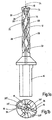
- Fig. 1a und b
- eine Seitenansicht und eine Draufsicht eines Bohrwerkzeugs mit Bohrkrone;
- Fig. 1c
- einen vergrößerten Ausschnitt des Bohrwerkzeugs nach
Fig. 1 a; - Fig. 2a und b
- zwei Seitenansichten der Bohrkrone des Bohrwerkzeugs in verschiedenen Drehstellungen;
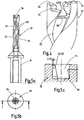
- Fig. 3a und b
- eine weitere Seitenansicht und eine Draufsicht der Bohrkrone zur Veranschaulichung der Schlüsselaufnahmen;
- Fig. 4
- eine schaubildliche Darstellung der Kupplungsaufnahme am Grundkörper;
- Fig. 5a und b
- eine Seitenansicht und eine Draufsicht des Grundkörpers;
- Fig. 5c
- einen Schnitt entlang der Schnittlinie C - C der
Fig. 5b in vergrößerter Darstellung; - Fig. 6a und b
- eine Seitenansicht und eine Untenansicht einer Bohrkrone mit Maßangaben;
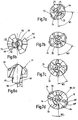
- Fig. 7a bis d
- Draufsichten auf das Bohrwerkzeug mit verschiedenen Drehlagen der Bohrkrone gegenüber dem Grundkörper zur Veranschaulichung des Eindrehens der Bohrkrone in den Grundkörper;
- Fig. 8
- ein Schema der ineinander greifenden, im Umriss teilkreisförmigen Spannflächen des Kupplungsteils und der Kupplungsaufnahme zur Erläuterung der Anordnung und Wirkung der exzentrischen Spannabschnitte des Kupplungsteils.
- 1a and b
- a side view and a plan view of a drilling tool with drill bit;
- Fig. 1c
- an enlarged section of the drilling tool
Fig. 1 a; - 2a and b
- two side views of the drill bit of the drilling tool in different rotational positions;
- 3a and b
- a further side view and a plan view of the drill bit to illustrate the key receptacles;
- Fig. 4
- a graphical representation of the coupling seat on the base body;
- 5a and b
- a side view and a plan view of the base body;
- Fig. 5c
- a section along the section line C - C of
Fig. 5b in an enlarged view; - 6a and b
- a side view and a bottom view of a drill bit with dimensions;
- 7a to d
- Top views of the drilling tool with different rotational positions of the drill bit in relation to the base body to illustrate the screwing of the drill bit into the base body;
- Fig. 8
- a diagram of the interlocking, in part circular outline clamping surfaces of the coupling part and the coupling receptacle to explain the arrangement and effect of the eccentric clamping sections of the coupling part.
Die in der Zeichnung dargestellten Bohrwerkzeuge sind an einer Trennstelle 30 zweigeteilt und bestehen aus einem einen Bohrerschaft 14 tragenden Grundkörper 32 und einer eine Bohrerspitze 10 aufweisenden Bohrkrone 34. Die Bohrkrone 34 und der Grundkörper 32 sind an der Trennstelle 30 form- und kraftschlüssig miteinander verbindbar. Während der Grundkörper 32 vorzugsweise aus Werkzeugstahl oder aus einem Schnellarbeitsstahl besteht, ist die Bohrkrone 34 als Formteil aus einem Schneidstoff aus der Gruppe Hartmetall oder Keramik gebildet, das als gesintertes Pulverspritzgussteil oder -pressteil hergestellt und gesintert wird. Grundsätzlich ist es auch möglich, die Bohrkrone 34 aus einem verschleißfest beschichteten Werkzeugstahl herzustellen.The drilling tools shown in the drawing are divided in two at a
Das in
Die radial über den Außenumfang der Bohrkrone 34 überstehenden Schneidkantenecken 84 gehen in eine Führungskante 86 über, an die in Umfangsrichtung eine sich über einen Teilumfang der Bohrkrone erstreckende, radial über den Außenumfang überstehende Führungsrippe 88 angrenzt.The cutting
Die in Spanablaufrichtung unmittelbar hinter den Hauptschneiden 16 beginnenden Spanfördernuten 22 sind auf der Seite der Schneiden durch je eine Spanfläche 90 begrenzt.The
An ihrer den Haupt- und Nebenfreiflächen 20',20" gegenüberliegenden Seite ist die Bohrkrone 34 mit einem Kupplungsteil 96 versehen, das unter Bildung der Trennstelle 30 mit einer stirnseitig am Grundkörper 32 angeordneten Kupplungsaufnahme 94 kuppelbar ist. Das Kupplungsteil 96 weist zu diesem Zweck zwei über den Umfang verteilt angeordnete, konvex gekrümmte Zentrierabschnitte 40 auf, die in hierzu komplementäre, konkav gekrümmte Zentrierabschnitte 42 der Kupplungsaufnahme 94 eingreifen. Weiter weist das Kupplungsteil 96 einen mit einem Drehmitnehmer 44 der Kupplungsaufnahme 94 kämmenden komplementären Mitnehmeranschlag 46 auf.On its side opposite the main and secondary
Eine Besonderheit der Erfindung besteht darin, dass die Zentrierabschnitte 40,42 des Kupplungsteils 96 und der Kupplungsaufnahme 94 bis zum Anschlagen des Mitnehmeranschlags 46 entgegen einer durch die Schneidrichtung der Hauptschneiden 16 bestimmten Arbeitsdrehrichtung um die Drehachse 24 auf einander drehkeilartig auflaufende Spannflächen 48,50 aufweisen. Die Spannflächen 48,50 des Kupplungsteils 96 weisen zu diesem Zweck einander diametral gegenüberliegende, zueinander exzentrische Kreisabschnitte auf (vgl.
Wie aus
Zur Erläuterung der bei der Montage auftretenden Exzenterbewegungen zwischen dem Kupplungsteil 96 und der Kupplungsaufnahme 44 sind in dem Schema der
Wie insbesondere aus
Um das Ein- und Ausspannen der Bohrkrone 34 am Grundkörper 32 zu erleichtern, sind im Bereich der Nebenfreiflächen 20" der Bohrkrone zwei in Umfangsrichtung einen Winkelabstand von etwa 180° voneinander aufweisende Schlüsseleingriffe 64 angeordnet, die sowohl in axialer als auch in radialer Richtung randoffen sind. Die Schlüsseleingriffe 64 haben im Wesentlichen parallel zur Drehachse 24 ausgerichtete, durch einen Eingriffsboden 66 begrenzte Schlüsselanschlagsflächen 68, die in Schließ- und Öffnungsrichtung etwa gleich hoch sind (vgl.
Claims (15)
- A drilling tool with a basic body (32) having a central axis of rotation (24) and with a drill bit (34) connected releasably to the basic body (32), the drill bit (34) having a coupling part (96) which is couplable to an end-face coupling receptacle (94) of the basic body (32) and which has at least two convexly curved centering portions (40) which are arranged so as to be distributed over the circumference and which engage with an exact fit into concavely curved centering portions (42), complementary to said convexly curved centering portions, of the coupling receptacle (94), the coupling part (96) having at least one complementary driver stop (46) meshing with a rotary driver (44) of the coupling receptacle (94), and the centering portions (40, 42) of the coupling part (96) and/or of the coupling receptacle (94) having, up to the mutual abutment of the driver stop (46) and of the rotary driver (44), tension faces (48, 50) running toward one another in the manner of a rotary wedge opposite to a predetermined working direction of rotation, characterized in that the tension faces (48, 50) of the coupling part (96) have in outline circle segments (40") which lie diametrically opposite one another and are eccentric with respect to the axis of rotation (24) and that the concave centering portions (42) of the coupling receptacle (94) form in cross section part circles concentric with respect to the axis of rotation and having a predetermined radius (R1), and in that the convex centering portions (40) of the coupling part (96) have a part-circular guide portion (40') concentric with respect to the axis of rotation, with a radius (R1) corresponding to the receptacle-side radius (R1), and a part-circular tension portion (40") tangentially adjoining said guide portion and eccentric with respect to the axis of rotation, with a radius (R2', R2") larger than the receptacle-side radius (R1), the eccentric tension portions (40") of the coupling part (96) and the part-circular centering portions (42) of the coupling receptacle (94) bearing non-positively one against the other in their tension position.
- The drilling tool as claimed in claim 1, characterized in that in each case at least one of the centering portions (40, 42) facing one another is at least partially elastically deformable or bendable so as to form a non-positive connection.
- The drilling tool as claimed in claim 1 or 2, characterized in that the coupling part (96) and the coupling receptacle (94) are rotatable with respect to one another in the manner of a bayonet fastening at their separation point (30).
- The drilling tool as claimed in one of claims 1 to 3, characterized in that the tension faces (48, 50) form conical faces which face one another in pairs and complete one another to form a cone with a cone axis concentric with respect to the axis of rotation (24) and that the coupling part (96) and the coupling receptacle (94) have planar face portions (52, 54) which face one another and, in the coupling position, are pressed one against the other under the action of the conical tension faces (48, 50) and are oriented essentially perpendicularly with respect to the axis of rotation.
- The drilling tool as claimed in claim 4, characterized in that the cone angle is 1° to 8°, wherein the coupling-part-side cone angle is steeper than the coupling-receptacle-side cone angle.
- A drilling tool with a basic body (32) having a central axis of rotation (24) and with a drill bit (34) connected releasably to the basic body (32), the drill bit (34) having a coupling part (96) which is couplable to an end-face coupling receptacle (94) of the basic body (32) and which has at least two convexly curved centering portions (40) which are arranged so as to be distributed over the circumference and which engage with an exact fit into concavely curved centering portions (42), complementary to said convexly curved centering portions, of the coupling receptacle (94), the coupling part (96) having at least one complementary driver stop (46) meshing with a rotary driver (44) of the coupling receptacle (94), and the centering portions (40, 42) of the coupling part (96) and/or of the coupling receptacle (94) having, up to the mutual abutment of the driver stop (46) and of the rotary driver (44), tension faces (48, 50) running toward one another in the manner of a rotary wedge opposite to a predetermined working direction of rotation, wherein the tension faces (48, 50) form conical faces which face one another in pairs and complete one another to form a cone with a cone axis concentric with respect to the axis of rotation (24) and that the coupling part (96) and the coupling receptacle (94) have planar face portions (52, 54) which face one another and, in the coupling position, are pressed one against the other under the action of the conical tension faces (48, 50) and are oriented essentially perpendicularly with respect to the axis of rotation, characterized in that the tension faces (48, 50) of the coupling part (96) have in outline circle segments (40', 40") which lie diametrically opposite one another and are eccentric with respect to the axis of rotation (24) and with respect to one another and that the cone angle is 1° to 8°, wherein the coupling-part-side cone angle is steeper than the coupling-receptacle-side cone angle.
- The drilling tool as claimed in one of claim 4 to 6, characterized in that the conical tension faces (48, 50) form, in the tension position, a positive connection between the coupling receptacle (94) and the coupling part (96).
- The drilling tool as claimed in one of claims 1 to 7, characterized in that the driver stops (46) and the rotary drivers (44) have in pairs an abutment slope (60) which in the coupling state forms a positive connection between the basic body and the drill bit.
- The drilling tool as claimed in claim 8, characterized in that the abutment slope of the driver stop (46) of the drill bit (34) forms a planar or crowned face part (60') delimited by two marginal parts (60", 60"') which lie opposite one another and of which one is concavely curved and the other is convexly curved, and which, forming an acute angle, merge directly or indirectly via a relief (62), in each case into a planar face portion (52, 53) perpendicular with respect to the axis of rotation (24) of the drill bit (34), wherein the acute angles of the marginal parts (60", 60"') are substantially identical and correspond to a right angle reduced by the angle of incidence of the abutment slope (60).
- The drilling tool as claimed in one of claims 1 to 9, characterized in that the coupling part (96) and the coupling receptacle (94) have a preferably cylindrical, conical or crowned centering tenon (56) and a centering recess (58), complementary to this, as a precentering means.
- The drilling tool as claimed in one of claims 1 to 10, characterized in that at least two marginally open key engagement points (64) which are at an angular distance from one another in the circumferential direction are arranged in the region of the flanks or minor flanks (20', 20") of the drill bit (34).
- The drilling tool as claimed in claim 11, characterized in that the key engagement points (64) have an axial or a radial marginal orifice.
- The drilling tool as claimed in claim 11 or 12, characterized in that the key engagement points (64) have key abutment faces (68) which are oriented essentially parallel to the axis of rotation (24) and are delimited by an engagement bottom (66).
- The drilling tool as claimed in one of claims 1 to 13, characterized in that the basic body (32) has at least two chip-conveying grooves (22) delimited on their flanks by ribs (26), and in that there is arranged in each of the ribs (26) of the basic body (32) a coolant duct which has, at the drill-bit-side end of the basic body, an outlet orifice (36) arranged within one of the chip-conveying grooves (22).
- The drilling tool as claimed in claim 14, characterized in that the outlet orifices (36) form or issue into a marginally open channel running along the chip-conveying grooves (22), the channel merging in each case into a channel arranged in the drill bit (34) and leading to one of the major cutting edges (16).
Priority Applications (1)
| Application Number | Priority Date | Filing Date | Title |
|---|---|---|---|
| PL08786180T PL2197612T5 (en) | 2007-09-14 | 2008-07-16 | Drilling tool with drill bit |
Applications Claiming Priority (2)
| Application Number | Priority Date | Filing Date | Title |
|---|---|---|---|
| DE102007044095A DE102007044095A1 (en) | 2007-09-14 | 2007-09-14 | Drilling tool with drill bit |
| PCT/EP2008/059286 WO2009037020A1 (en) | 2007-09-14 | 2008-07-16 | Drilling tool with drill bit |
Publications (3)
| Publication Number | Publication Date |
|---|---|
| EP2197612A1 EP2197612A1 (en) | 2010-06-23 |
| EP2197612B1 EP2197612B1 (en) | 2012-02-08 |
| EP2197612B2 true EP2197612B2 (en) | 2020-02-12 |
Family
ID=39831698
Family Applications (1)
| Application Number | Title | Priority Date | Filing Date |
|---|---|---|---|
| EP08786180.3A Active EP2197612B2 (en) | 2007-09-14 | 2008-07-16 | Drilling tool with drill bit |
Country Status (13)
| Country | Link |
|---|---|
| US (1) | US8721235B2 (en) |
| EP (1) | EP2197612B2 (en) |
| JP (1) | JP2010538846A (en) |
| KR (1) | KR20100089822A (en) |
| CN (1) | CN101801576B (en) |
| AT (1) | ATE544552T1 (en) |
| BR (1) | BRPI0816945B1 (en) |
| DE (1) | DE102007044095A1 (en) |
| ES (1) | ES2380092T5 (en) |
| IL (1) | IL204272A (en) |
| PL (1) | PL2197612T5 (en) |
| RU (1) | RU2467837C2 (en) |
| WO (1) | WO2009037020A1 (en) |
Families Citing this family (56)
| Publication number | Priority date | Publication date | Assignee | Title |
|---|---|---|---|---|
| IL181295A (en) | 2007-02-12 | 2011-07-31 | Iscar Ltd | Tool with releasably mounted self-clamping cutting head |
| IL195804A (en) * | 2008-12-09 | 2012-12-31 | Iscar Ltd | Cutting tool having releasably mounted self-clamping cutting head |
| WO2010089861A1 (en) * | 2009-02-04 | 2010-08-12 | オーエスジー株式会社 | Bevel head replacement rotary tool, tip head, and tool body |
| SE533853C2 (en) | 2009-06-23 | 2011-02-08 | Sandvik Intellectual Property | Drilling tools for chip separating machining and release stop for this |
| SE533850C2 (en) | 2009-06-23 | 2011-02-08 | Sandvik Intellectual Property | Loop stop type drilling tools |
| SE533851C2 (en) * | 2009-06-23 | 2011-02-08 | Sandvik Intellectual Property | Drilling tools for chip separating machining as well as loose stop and basic body for this |
| WO2011070653A1 (en) * | 2009-12-08 | 2011-06-16 | オーエスジー株式会社 | Throw-away rotary tool |
| SE534648C2 (en) | 2010-03-26 | 2011-11-08 | Sandvik Intellectual Property | Rotatable tool for chip separating machining as well as loose stop and basic body for this |
| DE102010025653B4 (en) * | 2010-06-30 | 2018-09-20 | Kennametal Inc. | Rotary cutting tool |
| WO2012173291A1 (en) * | 2011-06-15 | 2012-12-20 | (주)시원 | Drill bit for removing an implant coupling screw and guide socket thereof |
| DE102012200690B4 (en) * | 2012-01-18 | 2021-06-17 | Kennametal Inc. | Rotary tool and cutting head for such a rotary tool |
| CN106862600A (en) * | 2012-06-01 | 2017-06-20 | 株式会社日研工作所 | The shank construction of end mill(ing) cutter |
| US9409241B2 (en) * | 2012-12-13 | 2016-08-09 | Iscar, Ltd. | Cutting tool and replaceable cutting head having spiral driven surfaces therefor |
| US9498829B2 (en) | 2013-03-06 | 2016-11-22 | Allied Machine & Engineering Corp. | Drilling system for deep holes |
| DE102013205889B3 (en) | 2013-04-03 | 2014-05-28 | Kennametal Inc. | Coupling structure e.g. cutting head for rotary tool e.g. drilling tool, has coupling pin with clamping faces and stop surfaces that are arranged in different dispensing areas |
| USD734790S1 (en) * | 2013-06-12 | 2015-07-21 | Element Six (Production) (Pty) Ltd | Drill bit tip |
| DE102013220884B4 (en) | 2013-10-15 | 2022-02-17 | Kennametal Inc. | Modular carrier tool and tool head |
| KR101509954B1 (en) * | 2013-10-29 | 2015-04-07 | 한국야금 주식회사 | Cutting insert and Indexable Drill |
| CN103660044B (en) * | 2013-12-03 | 2015-11-18 | 常州深倍超硬材料有限公司 | There is the gang tool of cooling structure |
| DE102014103906B4 (en) * | 2014-03-21 | 2022-08-25 | Gühring KG | Partially hardened turning tool and related manufacturing method |
| DE102014206796B4 (en) | 2014-04-08 | 2020-10-15 | Kennametal Inc. | Rotary tool, in particular drill and cutting head for such a rotary tool |
| DE102015106082A1 (en) * | 2014-04-24 | 2015-10-29 | Kennametal India Ltd. | Cutting tool with replaceable cutting insert and inclined fasteners |
| US9468979B2 (en) * | 2014-06-17 | 2016-10-18 | Iscar, Ltd. | Rotary cutting tool including cutting head having coupling pin with guiding and fastening recesses |
| JP1526222S (en) | 2014-08-01 | 2015-06-15 | ||
| JP1526223S (en) | 2014-08-01 | 2015-06-15 | ||
| CN104759664A (en) * | 2015-04-21 | 2015-07-08 | 成都锋宜精密工具制造有限公司 | Self-locking type head-replaceable carbide drill |
| CN104907613A (en) * | 2015-05-18 | 2015-09-16 | 浙江欣兴工具有限公司 | Replaceable cutter head type drill bit |
| CN104907612B (en) * | 2015-05-18 | 2018-03-09 | 浙江欣兴工具有限公司 | A kind of drill bit of interchangeable cutter bit type structure |
| DE102015211744B4 (en) | 2015-06-24 | 2023-07-20 | Kennametal Inc. | Rotary tool, in particular a drill, and cutting head for such a rotary tool |
| USD798921S1 (en) | 2015-10-07 | 2017-10-03 | Kennametal Inc. | Cutting head for modular drill |
| US10071430B2 (en) | 2015-10-07 | 2018-09-11 | Kennametal Inc. | Cutting head, rotary tool and support for the rotary tool and for the accommodation of the cutting head |
| US9937567B2 (en) | 2015-10-07 | 2018-04-10 | Kennametal Inc. | Modular drill |
| USD798922S1 (en) | 2015-10-07 | 2017-10-03 | Kennametal Inc. | Cutting head for rotary drill |
| DE102015220777B4 (en) * | 2015-10-23 | 2020-08-13 | Kennametal Inc. | Tool coupling between two coupling parts as well as coupling part for such a tool coupling |
| DE102015220791B4 (en) * | 2015-10-23 | 2020-08-13 | Kennametal Inc. | Rotary tool, in particular drill and cutting head for such a rotary tool |
| CN105569573A (en) * | 2015-12-15 | 2016-05-11 | 武汉地大长江钻头有限公司 | PDC drill bit applicable to core drilling of moon |
| US11235397B2 (en) | 2016-12-16 | 2022-02-01 | Kennametal Inc. | Side-activated modular drill |
| ES2810673T3 (en) * | 2016-12-23 | 2021-03-09 | Walter Ag | One ball nose end mill insert, one ball nose end mill tool body, and one ball nose end mill |
| RU2675790C2 (en) * | 2017-01-10 | 2018-12-25 | Анна Борисовна Шмелева | Method of forensic control of sawed wood and device for its implementation |
| DE102017204452B4 (en) | 2017-03-16 | 2022-02-17 | Kennametal Inc. | rotation tool |
| DE102017205166B4 (en) * | 2017-03-27 | 2021-12-09 | Kennametal Inc. | Modular rotary tool and modular tool system |
| US11744672B2 (en) * | 2017-05-02 | 2023-09-05 | Straumann Holding Ag | Dental drill |
| DE102017212054B4 (en) | 2017-07-13 | 2019-02-21 | Kennametal Inc. | Method for producing a cutting head and cutting head |
| DE102017214165B4 (en) * | 2017-08-14 | 2021-10-14 | Kennametal Inc. | Rotary tool as well as carrier and cutting insert for such |
| US10799958B2 (en) | 2017-08-21 | 2020-10-13 | Kennametal Inc. | Modular rotary cutting tool |
| CN107575162A (en) * | 2017-09-15 | 2018-01-12 | 陈彬 | A kind of perforating device for building and its method of work |
| EP3488952B1 (en) * | 2017-11-24 | 2024-03-13 | Seco Tools Ab | A method for manufacturing a tool head |
| US11110521B2 (en) * | 2018-03-07 | 2021-09-07 | Iscar, Ltd. | Rotary cutting head having a rigid mounting protuberance and rotary cutting tool |
| DE102019116160A1 (en) | 2018-06-20 | 2019-12-24 | Kennametal Inc. | Modular drill bit closed on the side with spring-assisted ejection |
| CN109465483B (en) * | 2018-12-07 | 2020-06-26 | 西安交通大学 | Cutting tool with self-cooling lubricating structure |
| US11090736B2 (en) | 2018-12-10 | 2021-08-17 | Kennametal Inc. | Side-activated modular drill |
| CN112077370A (en) | 2019-06-13 | 2020-12-15 | 肯纳金属印度有限公司 | Indexable drill insert |
| US11471952B2 (en) | 2020-03-19 | 2022-10-18 | Kennametal Inc. | Cutting tool having replaceable cutting head and method of securing a replaceable cutting head |
| USD1009108S1 (en) | 2020-09-21 | 2023-12-26 | Kyocera Unimerco Tooling A/S | Drill |
| US11883888B2 (en) | 2021-06-28 | 2024-01-30 | Kennametal Inc. | Modular drill with enhanced bump-off capability |
| CN115026332A (en) * | 2022-07-18 | 2022-09-09 | 杭州超尔切削工具有限公司 | Drill bit with replaceable head |
Family Cites Families (30)
| Publication number | Priority date | Publication date | Assignee | Title |
|---|---|---|---|---|
| US1017352A (en) * | 1911-12-21 | 1912-02-13 | Frederick A Wagner | Combined drill, center-reamer, and countersink tool. |
| DE3106120A1 (en) | 1981-02-19 | 1983-01-13 | Iscar Hartmetall GmbH, 7505 Ettlingen | TOOL HOLDER TO RECEIVE A CUTTING INSERT |
| SU1248729A1 (en) * | 1984-12-03 | 1986-08-07 | Ленинградский Ордена Ленина И Ордена Красного Знамени Механический Институт | Drilling head |
| US5011342A (en) * | 1988-03-14 | 1991-04-30 | 501 Greenfield Industries, Inc. | Twist drill |
| DE4239311C2 (en) * | 1992-11-23 | 1996-04-18 | Guehring Joerg Dr | Drills, especially pointed drilling tools with exchangeable cutting inserts |
| IL105758A (en) * | 1993-05-20 | 1996-01-31 | Iscar Ltd | Indexable-insert drill |
| JPH11500967A (en) * | 1995-03-03 | 1999-01-26 | コメート プレツィジオーンスヴェルクツォイゲ ローベルト ブロイニング ゲゼルシャフト ミット ベシュレンクテル ハフツング | Drilling tool |
| CA2226754A1 (en) * | 1995-07-14 | 1997-02-06 | Kennametal Hertel Ag Werkzeuge + Hartstoffe | Drill with cooling-lubricant channel |
| US6116825A (en) * | 1995-08-08 | 2000-09-12 | Kennametal Hertel Ag Werkzeuge + Hartstoffe | Rotating cutting tool with a coolant passage and a method of providing it with coolant |
| DE19543233A1 (en) * | 1995-11-07 | 1997-05-15 | Johne & Co Praezisionswerkzeug | Drill tool with interchangeable tip |
| JP2905142B2 (en) * | 1996-05-08 | 1999-06-14 | 富士精工株式会社 | Drill |
| SE511429C2 (en) | 1996-09-13 | 1999-09-27 | Seco Tools Ab | Tools, cutting part, tool body for cutting machining and method of mounting cutting part to tool body |
| IL120948A0 (en) * | 1997-05-29 | 1997-09-30 | Iscar Ltd | Cutting tool assembly |
| KR100639527B1 (en) * | 1999-08-03 | 2006-10-30 | 케나메탈 아이엔씨. | Drill bit having a replaceable cutting head |
| DE10042990A1 (en) * | 2000-09-01 | 2002-03-28 | Kennametal Inc | Run-out cutting tool, e.g. B. drills |
| US6485235B1 (en) | 2001-05-08 | 2002-11-26 | Allied Machine & Engineering Corp. | Cutting tool assembly with replaceable cutting head |
| US6506003B1 (en) * | 2001-10-02 | 2003-01-14 | Kennametal Inc. | Cutting tool |
| SE523616C2 (en) * | 2001-10-25 | 2004-05-04 | Sandvik Ab | Rotary tool for chip separating machining with coupling device with elastic legs |
| DE10207257B4 (en) * | 2002-02-21 | 2021-02-18 | Kennametal Inc. | Rotary cutting tool with exchangeable cutting insert |
| JP2005014165A (en) * | 2003-06-26 | 2005-01-20 | Kyocera Corp | Throw-away drill |
| DE10333340A1 (en) * | 2003-07-23 | 2005-02-17 | Kennametal Inc. | Drill tool, comprising coolant ducts arranged parallel to central axis with outlets positioned in cutting grooves |
| WO2005081890A2 (en) * | 2004-02-20 | 2005-09-09 | Henry James D | Archimedean conveyors and combustion engines |
| IL162147A (en) * | 2004-05-24 | 2008-03-20 | Gil Hecht | Drill with releasably mounted cutting head |
| IL163679A (en) * | 2004-08-23 | 2009-02-11 | Gil Hecht | Gun-drill |
| US7244081B2 (en) * | 2004-09-09 | 2007-07-17 | Ingersoll Cutting Tool Company | Drill adapter for drill having central and lateral cutting inserts |
| US7309196B2 (en) * | 2004-10-05 | 2007-12-18 | Kennametal Inc. | Modular drill |
| JP2006128238A (en) * | 2004-10-27 | 2006-05-18 | Aqua Science Kk | Object treatment device and object treatment method |
| IL164888A (en) * | 2004-10-28 | 2009-07-20 | Iscar Ltd | Cutting tool assembly and cutting head therefor |
| RU2294266C1 (en) * | 2005-09-19 | 2007-02-27 | Нина Алексеевна Корюкина | Cutter |
| WO2008014367A1 (en) | 2006-07-26 | 2008-01-31 | Allied Machine & Engineering Corp. | Cutting tool with replaceable tip |
-
2007
- 2007-09-14 DE DE102007044095A patent/DE102007044095A1/en not_active Ceased
-
2008
- 2008-07-16 ES ES08786180T patent/ES2380092T5/en active Active
- 2008-07-16 PL PL08786180T patent/PL2197612T5/en unknown
- 2008-07-16 BR BRPI0816945-4A patent/BRPI0816945B1/en active IP Right Grant
- 2008-07-16 CN CN2008801069632A patent/CN101801576B/en active Active
- 2008-07-16 KR KR1020107007843A patent/KR20100089822A/en not_active Application Discontinuation
- 2008-07-16 EP EP08786180.3A patent/EP2197612B2/en active Active
- 2008-07-16 AT AT08786180T patent/ATE544552T1/en active
- 2008-07-16 WO PCT/EP2008/059286 patent/WO2009037020A1/en active Application Filing
- 2008-07-16 JP JP2010524426A patent/JP2010538846A/en active Pending
- 2008-07-16 RU RU2010114754/02A patent/RU2467837C2/en active
- 2008-07-16 US US12/733,669 patent/US8721235B2/en active Active
-
2010
- 2010-03-03 IL IL204272A patent/IL204272A/en active IP Right Grant
Also Published As
| Publication number | Publication date |
|---|---|
| EP2197612B1 (en) | 2012-02-08 |
| ES2380092T3 (en) | 2012-05-08 |
| US8721235B2 (en) | 2014-05-13 |
| CN101801576A (en) | 2010-08-11 |
| PL2197612T5 (en) | 2020-08-10 |
| ATE544552T1 (en) | 2012-02-15 |
| BRPI0816945A2 (en) | 2015-03-24 |
| EP2197612A1 (en) | 2010-06-23 |
| JP2010538846A (en) | 2010-12-16 |
| BRPI0816945B1 (en) | 2019-10-15 |
| WO2009037020A1 (en) | 2009-03-26 |
| IL204272A (en) | 2015-05-31 |
| RU2467837C2 (en) | 2012-11-27 |
| KR20100089822A (en) | 2010-08-12 |
| BRPI0816945A8 (en) | 2018-05-08 |
| CN101801576B (en) | 2012-09-12 |
| ES2380092T5 (en) | 2020-08-13 |
| DE102007044095A1 (en) | 2009-03-19 |
| PL2197612T3 (en) | 2012-07-31 |
| RU2010114754A (en) | 2011-10-20 |
| US20100266357A1 (en) | 2010-10-21 |
Similar Documents
| Publication | Publication Date | Title |
|---|---|---|
| EP2197612B2 (en) | Drilling tool with drill bit | |
| EP0813459B1 (en) | Drilling tool | |
| DE102014204700B4 (en) | Rotary tool, in particular drilling tool and method for producing a rotary tool | |
| DE102011105978B4 (en) | Indexable insert and face milling cutter with indexable insert | |
| EP0151251B1 (en) | Drill having a plurality of cutting edges | |
| WO1999000209A1 (en) | Twist drill for dry boring | |
| EP2337649B1 (en) | Thread former having molding | |
| WO2013003874A1 (en) | Drill cutting insert | |
| WO1992020483A1 (en) | Drilling tool | |
| EP0450026A1 (en) | Twist drill | |
| DE10021879A1 (en) | Solid drill for machine tools has two or more reversible cutting plates with main cutting blades and secondary cutting blades perpendicular thereto with a working angle of less than three point two degrees | |
| DE3730377C2 (en) | drill | |
| WO2004087355A1 (en) | Tool for machine tools | |
| DE2246965A1 (en) | TWIST DRILLS | |
| DE202011050277U1 (en) | drilling | |
| DE2856363C2 (en) | Drilling tool | |
| WO2017020051A1 (en) | Replaceable cutting head, tool shank, and shank-mounted tool | |
| WO2007000430A1 (en) | End milling cutter | |
| WO2010111994A1 (en) | Single-lip deep hole drill | |
| DE102014207502A1 (en) | Rotary tool and tool head | |
| EP3512663A1 (en) | Milling tool and production method for a milling tool | |
| WO2012159881A2 (en) | Rock drill | |
| DE2756990C2 (en) | Rock drill | |
| DE102014209135B3 (en) | Tool head and rotary tool with such | |
| DE10359854A1 (en) | Cylinder head drilling tool for use during processing of e.g. wood, has tool body with head, and cutting plate connected to front face of head, where body is made of fiber-reinforced plastic e.g. carbon/glass fiber-reinforced plastic |
Legal Events
| Date | Code | Title | Description |
|---|---|---|---|
| PUAI | Public reference made under article 153(3) epc to a published international application that has entered the european phase |
Free format text: ORIGINAL CODE: 0009012 |
|
| 17P | Request for examination filed |
Effective date: 20100310 |
|
| AK | Designated contracting states |
Kind code of ref document: A1 Designated state(s): AT BE BG CH CY CZ DE DK EE ES FI FR GB GR HR HU IE IS IT LI LT LU LV MC MT NL NO PL PT RO SE SI SK TR |
|
| AX | Request for extension of the european patent |
Extension state: AL BA MK RS |
|
| RIN1 | Information on inventor provided before grant (corrected) |
Inventor name: OETTLE, MATTHIAS Inventor name: LUIK, MATTHIAS Inventor name: SCHUETT, HENRY Inventor name: SCHNEIDER, RICO Inventor name: KRETZSCHMANN, UWE |
|
| 17Q | First examination report despatched |
Effective date: 20101025 |
|
| DAX | Request for extension of the european patent (deleted) | ||
| GRAP | Despatch of communication of intention to grant a patent |
Free format text: ORIGINAL CODE: EPIDOSNIGR1 |
|
| GRAS | Grant fee paid |
Free format text: ORIGINAL CODE: EPIDOSNIGR3 |
|
| GRAA | (expected) grant |
Free format text: ORIGINAL CODE: 0009210 |
|
| AK | Designated contracting states |
Kind code of ref document: B1 Designated state(s): AT BE BG CH CY CZ DE DK EE ES FI FR GB GR HR HU IE IS IT LI LT LU LV MC MT NL NO PL PT RO SE SI SK TR |
|
| REG | Reference to a national code |
Ref country code: GB Ref legal event code: FG4D Free format text: NOT ENGLISH |
|
| REG | Reference to a national code |
Ref country code: AT Ref legal event code: REF Ref document number: 544552 Country of ref document: AT Kind code of ref document: T Effective date: 20120215 Ref country code: CH Ref legal event code: EP |
|
| REG | Reference to a national code |
Ref country code: NL Ref legal event code: T3 |
|
| REG | Reference to a national code |
Ref country code: DE Ref legal event code: R096 Ref document number: 502008006360 Country of ref document: DE Effective date: 20120405 |
|
| REG | Reference to a national code |
Ref country code: ES Ref legal event code: FG2A Ref document number: 2380092 Country of ref document: ES Kind code of ref document: T3 Effective date: 20120508 |
|
| REG | Reference to a national code |
Ref country code: SE Ref legal event code: TRGR |
|
| LTIE | Lt: invalidation of european patent or patent extension |
Effective date: 20120208 |
|
| PG25 | Lapsed in a contracting state [announced via postgrant information from national office to epo] |
Ref country code: HR Free format text: LAPSE BECAUSE OF FAILURE TO SUBMIT A TRANSLATION OF THE DESCRIPTION OR TO PAY THE FEE WITHIN THE PRESCRIBED TIME-LIMIT Effective date: 20120208 Ref country code: NO Free format text: LAPSE BECAUSE OF FAILURE TO SUBMIT A TRANSLATION OF THE DESCRIPTION OR TO PAY THE FEE WITHIN THE PRESCRIBED TIME-LIMIT Effective date: 20120508 Ref country code: IS Free format text: LAPSE BECAUSE OF FAILURE TO SUBMIT A TRANSLATION OF THE DESCRIPTION OR TO PAY THE FEE WITHIN THE PRESCRIBED TIME-LIMIT Effective date: 20120608 Ref country code: LT Free format text: LAPSE BECAUSE OF FAILURE TO SUBMIT A TRANSLATION OF THE DESCRIPTION OR TO PAY THE FEE WITHIN THE PRESCRIBED TIME-LIMIT Effective date: 20120208 |
|
| REG | Reference to a national code |
Ref country code: PL Ref legal event code: T3 |
|
| REG | Reference to a national code |
Ref country code: IE Ref legal event code: FD4D |
|
| PG25 | Lapsed in a contracting state [announced via postgrant information from national office to epo] |
Ref country code: GR Free format text: LAPSE BECAUSE OF FAILURE TO SUBMIT A TRANSLATION OF THE DESCRIPTION OR TO PAY THE FEE WITHIN THE PRESCRIBED TIME-LIMIT Effective date: 20120509 Ref country code: FI Free format text: LAPSE BECAUSE OF FAILURE TO SUBMIT A TRANSLATION OF THE DESCRIPTION OR TO PAY THE FEE WITHIN THE PRESCRIBED TIME-LIMIT Effective date: 20120208 Ref country code: LV Free format text: LAPSE BECAUSE OF FAILURE TO SUBMIT A TRANSLATION OF THE DESCRIPTION OR TO PAY THE FEE WITHIN THE PRESCRIBED TIME-LIMIT Effective date: 20120208 Ref country code: PT Free format text: LAPSE BECAUSE OF FAILURE TO SUBMIT A TRANSLATION OF THE DESCRIPTION OR TO PAY THE FEE WITHIN THE PRESCRIBED TIME-LIMIT Effective date: 20120608 |
|
| PG25 | Lapsed in a contracting state [announced via postgrant information from national office to epo] |
Ref country code: CY Free format text: LAPSE BECAUSE OF FAILURE TO SUBMIT A TRANSLATION OF THE DESCRIPTION OR TO PAY THE FEE WITHIN THE PRESCRIBED TIME-LIMIT Effective date: 20120208 |
|
| PG25 | Lapsed in a contracting state [announced via postgrant information from national office to epo] |
Ref country code: EE Free format text: LAPSE BECAUSE OF FAILURE TO SUBMIT A TRANSLATION OF THE DESCRIPTION OR TO PAY THE FEE WITHIN THE PRESCRIBED TIME-LIMIT Effective date: 20120208 Ref country code: RO Free format text: LAPSE BECAUSE OF FAILURE TO SUBMIT A TRANSLATION OF THE DESCRIPTION OR TO PAY THE FEE WITHIN THE PRESCRIBED TIME-LIMIT Effective date: 20120208 Ref country code: SI Free format text: LAPSE BECAUSE OF FAILURE TO SUBMIT A TRANSLATION OF THE DESCRIPTION OR TO PAY THE FEE WITHIN THE PRESCRIBED TIME-LIMIT Effective date: 20120208 Ref country code: DK Free format text: LAPSE BECAUSE OF FAILURE TO SUBMIT A TRANSLATION OF THE DESCRIPTION OR TO PAY THE FEE WITHIN THE PRESCRIBED TIME-LIMIT Effective date: 20120208 Ref country code: IE Free format text: LAPSE BECAUSE OF FAILURE TO SUBMIT A TRANSLATION OF THE DESCRIPTION OR TO PAY THE FEE WITHIN THE PRESCRIBED TIME-LIMIT Effective date: 20120208 |
|
| PLBI | Opposition filed |
Free format text: ORIGINAL CODE: 0009260 |
|
| PG25 | Lapsed in a contracting state [announced via postgrant information from national office to epo] |
Ref country code: SK Free format text: LAPSE BECAUSE OF FAILURE TO SUBMIT A TRANSLATION OF THE DESCRIPTION OR TO PAY THE FEE WITHIN THE PRESCRIBED TIME-LIMIT Effective date: 20120208 |
|
| 26 | Opposition filed |
Opponent name: KENNAMETAL INC. Effective date: 20121105 |
|
| PLAX | Notice of opposition and request to file observation + time limit sent |
Free format text: ORIGINAL CODE: EPIDOSNOBS2 |
|
| PGFP | Annual fee paid to national office [announced via postgrant information from national office to epo] |
Ref country code: HU Payment date: 20120801 Year of fee payment: 5 |
|
| BERE | Be: lapsed |
Owner name: HARTMETALL-WERKZEUGFABRIK PAUL HORN G.M.B.H. Effective date: 20120731 Owner name: KOMET GROUP G.M.B.H. Effective date: 20120731 |
|
| REG | Reference to a national code |
Ref country code: DE Ref legal event code: R026 Ref document number: 502008006360 Country of ref document: DE Effective date: 20121105 |
|
| PG25 | Lapsed in a contracting state [announced via postgrant information from national office to epo] |
Ref country code: MC Free format text: LAPSE BECAUSE OF NON-PAYMENT OF DUE FEES Effective date: 20120731 |
|
| REG | Reference to a national code |
Ref country code: HU Ref legal event code: AG4A Ref document number: E014577 Country of ref document: HU |
|
| PLAF | Information modified related to communication of a notice of opposition and request to file observations + time limit |
Free format text: ORIGINAL CODE: EPIDOSCOBS2 |
|
| PG25 | Lapsed in a contracting state [announced via postgrant information from national office to epo] |
Ref country code: BE Free format text: LAPSE BECAUSE OF NON-PAYMENT OF DUE FEES Effective date: 20120731 |
|
| PLBB | Reply of patent proprietor to notice(s) of opposition received |
Free format text: ORIGINAL CODE: EPIDOSNOBS3 |
|
| PG25 | Lapsed in a contracting state [announced via postgrant information from national office to epo] |
Ref country code: MT Free format text: LAPSE BECAUSE OF FAILURE TO SUBMIT A TRANSLATION OF THE DESCRIPTION OR TO PAY THE FEE WITHIN THE PRESCRIBED TIME-LIMIT Effective date: 20120208 Ref country code: BG Free format text: LAPSE BECAUSE OF FAILURE TO SUBMIT A TRANSLATION OF THE DESCRIPTION OR TO PAY THE FEE WITHIN THE PRESCRIBED TIME-LIMIT Effective date: 20120508 |
|
| PG25 | Lapsed in a contracting state [announced via postgrant information from national office to epo] |
Ref country code: HU Free format text: LAPSE BECAUSE OF NON-PAYMENT OF DUE FEES Effective date: 20130717 Ref country code: TR Free format text: LAPSE BECAUSE OF FAILURE TO SUBMIT A TRANSLATION OF THE DESCRIPTION OR TO PAY THE FEE WITHIN THE PRESCRIBED TIME-LIMIT Effective date: 20120208 |
|
| PG25 | Lapsed in a contracting state [announced via postgrant information from national office to epo] |
Ref country code: LU Free format text: LAPSE BECAUSE OF NON-PAYMENT OF DUE FEES Effective date: 20120716 |
|
| REG | Reference to a national code |
Ref country code: AT Ref legal event code: MM01 Ref document number: 544552 Country of ref document: AT Kind code of ref document: T Effective date: 20130716 |
|
| PG25 | Lapsed in a contracting state [announced via postgrant information from national office to epo] |
Ref country code: AT Free format text: LAPSE BECAUSE OF NON-PAYMENT OF DUE FEES Effective date: 20130716 |
|
| PLCK | Communication despatched that opposition was rejected |
Free format text: ORIGINAL CODE: EPIDOSNREJ1 |
|
| APAH | Appeal reference modified |
Free format text: ORIGINAL CODE: EPIDOSCREFNO |
|
| APBM | Appeal reference recorded |
Free format text: ORIGINAL CODE: EPIDOSNREFNO |
|
| APBP | Date of receipt of notice of appeal recorded |
Free format text: ORIGINAL CODE: EPIDOSNNOA2O |
|
| APBQ | Date of receipt of statement of grounds of appeal recorded |
Free format text: ORIGINAL CODE: EPIDOSNNOA3O |
|
| REG | Reference to a national code |
Ref country code: FR Ref legal event code: PLFP Year of fee payment: 9 |
|
| REG | Reference to a national code |
Ref country code: FR Ref legal event code: PLFP Year of fee payment: 10 |
|
| REG | Reference to a national code |
Ref country code: FR Ref legal event code: PLFP Year of fee payment: 11 |
|
| APBU | Appeal procedure closed |
Free format text: ORIGINAL CODE: EPIDOSNNOA9O |
|
| PUAH | Patent maintained in amended form |
Free format text: ORIGINAL CODE: 0009272 |
|
| STAA | Information on the status of an ep patent application or granted ep patent |
Free format text: STATUS: PATENT MAINTAINED AS AMENDED |
|
| REG | Reference to a national code |
Ref country code: CH Ref legal event code: AELC |
|
| 27A | Patent maintained in amended form |
Effective date: 20200212 |
|
| AK | Designated contracting states |
Kind code of ref document: B2 Designated state(s): AT BE BG CH CY CZ DE DK EE ES FI FR GB GR HR HU IE IS IT LI LT LU LV MC MT NL NO PL PT RO SE SI SK TR |
|
| REG | Reference to a national code |
Ref country code: DE Ref legal event code: R102 Ref document number: 502008006360 Country of ref document: DE |
|
| REG | Reference to a national code |
Ref country code: NL Ref legal event code: FP |
|
| REG | Reference to a national code |
Ref country code: SE Ref legal event code: RPEO |
|
| REG | Reference to a national code |
Ref country code: ES Ref legal event code: DC2A Ref document number: 2380092 Country of ref document: ES Kind code of ref document: T5 Effective date: 20200813 |
|
| PGFP | Annual fee paid to national office [announced via postgrant information from national office to epo] |
Ref country code: NL Payment date: 20230719 Year of fee payment: 16 |
|
| PGFP | Annual fee paid to national office [announced via postgrant information from national office to epo] |
Ref country code: IT Payment date: 20230724 Year of fee payment: 16 Ref country code: GB Payment date: 20230720 Year of fee payment: 16 Ref country code: ES Payment date: 20230926 Year of fee payment: 16 Ref country code: CZ Payment date: 20230711 Year of fee payment: 16 Ref country code: CH Payment date: 20230801 Year of fee payment: 16 |
|
| PGFP | Annual fee paid to national office [announced via postgrant information from national office to epo] |
Ref country code: SE Payment date: 20230719 Year of fee payment: 16 Ref country code: PL Payment date: 20230707 Year of fee payment: 16 Ref country code: FR Payment date: 20230725 Year of fee payment: 16 Ref country code: DE Payment date: 20230719 Year of fee payment: 16 |