EP2191300B1 - Low- power satellite-timed seismic data acquisition system - Google Patents
Low- power satellite-timed seismic data acquisition system Download PDFInfo
- Publication number
- EP2191300B1 EP2191300B1 EP08831527.0A EP08831527A EP2191300B1 EP 2191300 B1 EP2191300 B1 EP 2191300B1 EP 08831527 A EP08831527 A EP 08831527A EP 2191300 B1 EP2191300 B1 EP 2191300B1
- Authority
- EP
- European Patent Office
- Prior art keywords
- recorder
- seismic
- recorders
- processor
- operatively coupled
- Prior art date
- Legal status (The legal status is an assumption and is not a legal conclusion. Google has not performed a legal analysis and makes no representation as to the accuracy of the status listed.)
- Active
Links
- 230000015654 memory Effects 0.000 claims description 33
- 238000000034 method Methods 0.000 claims description 11
- 230000006870 function Effects 0.000 claims description 9
- 230000001360 synchronised effect Effects 0.000 claims description 6
- 230000008859 change Effects 0.000 claims description 5
- 239000004020 conductor Substances 0.000 claims 1
- 230000000694 effects Effects 0.000 claims 1
- 230000005714 functional activity Effects 0.000 claims 1
- 238000012545 processing Methods 0.000 description 27
- 238000005070 sampling Methods 0.000 description 8
- 238000013480 data collection Methods 0.000 description 5
- 238000010586 diagram Methods 0.000 description 5
- 238000004891 communication Methods 0.000 description 4
- 230000002093 peripheral effect Effects 0.000 description 3
- 238000012546 transfer Methods 0.000 description 3
- 230000003044 adaptive effect Effects 0.000 description 2
- 230000008901 benefit Effects 0.000 description 2
- 230000000875 corresponding effect Effects 0.000 description 2
- 239000013078 crystal Substances 0.000 description 2
- 230000001419 dependent effect Effects 0.000 description 2
- 238000005259 measurement Methods 0.000 description 2
- 238000012360 testing method Methods 0.000 description 2
- 239000004215 Carbon black (E152) Substances 0.000 description 1
- 241000283984 Rodentia Species 0.000 description 1
- 230000006978 adaptation Effects 0.000 description 1
- 230000002411 adverse Effects 0.000 description 1
- 238000004458 analytical method Methods 0.000 description 1
- 238000003491 array Methods 0.000 description 1
- 230000015556 catabolic process Effects 0.000 description 1
- 230000001413 cellular effect Effects 0.000 description 1
- 238000006243 chemical reaction Methods 0.000 description 1
- 230000001276 controlling effect Effects 0.000 description 1
- 230000002596 correlated effect Effects 0.000 description 1
- 230000003247 decreasing effect Effects 0.000 description 1
- 238000006731 degradation reaction Methods 0.000 description 1
- 238000005265 energy consumption Methods 0.000 description 1
- 230000007613 environmental effect Effects 0.000 description 1
- 229930195733 hydrocarbon Natural products 0.000 description 1
- 150000002430 hydrocarbons Chemical class 0.000 description 1
- 244000144972 livestock Species 0.000 description 1
- 238000004519 manufacturing process Methods 0.000 description 1
- 238000005065 mining Methods 0.000 description 1
- 238000012986 modification Methods 0.000 description 1
- 230000004048 modification Effects 0.000 description 1
- 230000000737 periodic effect Effects 0.000 description 1
- 230000008569 process Effects 0.000 description 1
- 230000008439 repair process Effects 0.000 description 1
- 239000004065 semiconductor Substances 0.000 description 1
- 238000001228 spectrum Methods 0.000 description 1
- 210000000707 wrist Anatomy 0.000 description 1
Images


Classifications
-
- G—PHYSICS
- G01—MEASURING; TESTING
- G01V—GEOPHYSICS; GRAVITATIONAL MEASUREMENTS; DETECTING MASSES OR OBJECTS; TAGS
- G01V1/00—Seismology; Seismic or acoustic prospecting or detecting
- G01V1/003—Seismic data acquisition in general, e.g. survey design
-
- G—PHYSICS
- G01—MEASURING; TESTING
- G01V—GEOPHYSICS; GRAVITATIONAL MEASUREMENTS; DETECTING MASSES OR OBJECTS; TAGS
- G01V1/00—Seismology; Seismic or acoustic prospecting or detecting
- G01V1/16—Receiving elements for seismic signals; Arrangements or adaptations of receiving elements
- G01V1/162—Details
-
- G—PHYSICS
- G01—MEASURING; TESTING
- G01V—GEOPHYSICS; GRAVITATIONAL MEASUREMENTS; DETECTING MASSES OR OBJECTS; TAGS
- G01V1/00—Seismology; Seismic or acoustic prospecting or detecting
- G01V1/22—Transmitting seismic signals to recording or processing apparatus
-
- G—PHYSICS
- G01—MEASURING; TESTING
- G01V—GEOPHYSICS; GRAVITATIONAL MEASUREMENTS; DETECTING MASSES OR OBJECTS; TAGS
- G01V11/00—Prospecting or detecting by methods combining techniques covered by two or more of main groups G01V1/00 - G01V9/00
- G01V11/002—Details, e.g. power supply systems for logging instruments, transmitting or recording data, specially adapted for well logging, also if the prospecting method is irrelevant
-
- G—PHYSICS
- G01—MEASURING; TESTING
- G01V—GEOPHYSICS; GRAVITATIONAL MEASUREMENTS; DETECTING MASSES OR OBJECTS; TAGS
- G01V2200/00—Details of seismic or acoustic prospecting or detecting in general
- G01V2200/10—Miscellaneous details
- G01V2200/12—Clock synchronization-related issues
Definitions
- This invention relates generally to a seismic systems, and more particularly to seismic systems used in the hydrocarbon exploration and mining industries.
- Terrestrial seismic data acquisition systems are well known in the art.
- An array of geophones are positioned across a geographical region, typically in a grid pattern, for measuring seismic vibrations. The precise location of each geophone must be known and is typically ascertained by a separate positioning survey.
- a seismic vibration source is activated, and the geophone measurements are recorded, sometimes over a period of several hours to several days or weeks, collected, and subsequently processed to determine the structure of the earth at that geographical region.
- multi-channel digital recorders are connected to a number of input geophone channels for sampling and converting the analog geophone outputs to digital format, which are recorded. It is often preferred that the analog-to-digital conversion occurs in the field close to the geophones to minimize degradation of the low-level geophone signals.
- the seismic channel data are analyzed strictly according to their sequential sampling order, and timing errors are minimized by ensuring simultaneous triggering of all recorders to begin sampling. Triggering the digital recorders may be performed by hard-wired or wireless radio frequency (RF) control.
- RF radio frequency
- control and power are provided by cabling that connects the digital recorders to a control interface.
- This type of system has an additional advantage of having a conductive signal path to transmit seismic data from the numerous digital recorders for central collection, typically at a control vehicle.
- the cabling is heavy, and weight is a significant cost in deploying a seismic system.
- the cables are subject to damage by being crushed under passing vehicles or being chewed by rodents and livestock, for example.
- Wireless systems In wireless systems, the weight of the cabling between digital recorders is eliminated, but the weight savings is offset by batteries used to power the digital recorders and RF receivers used for triggering wireless systems.
- Wireless systems also typically employ RF transmitters in the digital recorders for transmitting seismic data to a central location for collection and processing.
- Large wireless seismic survey systems require a significant amount of RF bandwidth and a fairly large antenna at the control vehicle. Radio wave propagation paths may be obstructed by terrain, vegetation or structures.
- battery life limits the time a system may remain in the field, even in standby conditions, and creates logistical difficulties in deploying large seismic system arrays.
- Figure 1 illustrates a "wireless" seismic recording system of prior art in which strings of geophones (1) are connected to multi-channel digitizer modules (2), for example, six geophones per string and four channels per recorder. Because of the low-level signals produced by analog sensors, the digitizer modules (2) are each located in close proximity to their attached geophones. The digitizer modules (2) include preamplifiers and analog-to-digital converters to digitize the geophone signals into digital data. The seismic digital data are then in turn transmitted by the digitizer modules to a data acquisition module (3) via electrical cabling (4). Depending on the telemetry techniques employed, the data acquisition modules (3) may be located a significant distance away from the digitizer modules (2).
- Each data acquisition module contains memory for recording the digital seismic data from its corresponding family of digitizer modules, and the data acquisition module supplies power, control, and synchronized clock signals to the digitizer modules.
- Each data acquisition module has a battery, and it may also include a radio frequency transmitter for broadcasting collected seismic data to a control vehicle, for example. Timing synchronization is maintained between the geophone channels by including a global positioning receiver within each data acquisition module (3).
- Each data acquisition module (3) continuously processes satellite navigation data to provide a common time standard among the units.
- Other prior art seismic systems for example, U.S.
- Patent No. 5,978,313 issued to Longaker disclose seismic systems that employ satellite navigation system receivers for establishing synchronization among the recording units, but no provision is made for idling the satellite receiver to conserve power.
- US 2004/0105533 discloses a seismic data acquisition apparatus having a recorder co-located with a sensor unit, and a communication device for direct communication with a central recorder.
- a GPS receiver may be provided to provide location parameters such as position and location data for correlating seismic information and for synchronizing data acquisition.
- US 5,864,315 discloses a direct sequence spread spectrum signal processing system which permits the receiver to be turned off during most of the acquisition phase of reception to reduce the on time of the associated receiver front end.
- a primary object of the invention is to provide a seismic data acquisition system including field-deployable digital recorders for capturing seismic data that have integral satellite receivers for synchronizing the timing between recorded seismic data from multiple recorders, thus eliminating the cost of deploying traditional timing/triggering systems.
- Another object of the invention is to provide a wireless seismic acquisition system wherein the digital recorders are collocated with digitizing electronics near the analog sensors, thus minimizing the volume, weight and cost of cable to deploy and maintain.
- Another object of the invention is to provide a wireless digital seismic recorder with an independent acquisition clock circuit that is used to sample and to time stamp recorded seismic data and a satellite receiver that is activated only periodically to adjust the acquisition clock circuit. By not continuously processing satellite navigation signals, power requirements are reduced.
- Another object of the invention is to provide an intelligent digital seismic recorder that periodically adjusts a local acquisition clock circuit to a satellite time standard and that measures the acquisition clock drift and temperature changes and adjusts clock cycle times to maximize periods between synchronization while maintaining the acquisition clock circuit within a given error tolerance.
- Another object of the invention is to provide a seismic data acquisition system having field-deployable digital recorders that periodically record time stamps with seismic data and that are equipped with large non-volatile memories to eliminate the need for centralized triggering.
- Another object of the invention is to provide a seismic data acquisition system arranged for transferring recorded seismic data to collection computers in the field during surveys, after the data is collected.
- Another object of the invention is to provide a seismic data acquisition system having field-deployable digital recorders equipped with low-power-consumption electronics and that are designed and programmed to automatically and selectively de-energize or idle system components when not required for use, thus extending the usable time in field and reducing operating costs.
- Another object of the invention is to provide a seismic data acquisition system having field-deployable digital recorders which employ dynamic voltage control techniques to lower computer processor power consumption by idling the processor during periods of lower computational demands.
- a seismic recording system that includes cordless battery-operated digital seismic recorders.
- Each recorder is located with and adapted for connecting to one or more seismic sensors and for digitizing and recording single or multi-channel seismic data from the sensors. Rather than relying on the use of concurrent triggering to ensure multi-channel timing integrity, one or more time stamps are recorded with the digitized seismic data in non-volatile memory.
- Each recorder may commence recording independently of the others and includes memory of sufficient capacity to allow extended periods of operation.
- Each recorder includes its own acquisition clock, processing system, and global positioning system (GPS) receiver for the purpose of establishing synchronization of recorded seismic data among the many recorders typically required for a survey.
- the processing system is arranged for periodically synchronizing the acquisition clock to a satellite time standard derived by the GPS receiver.
- Each recorder preferably includes a low-power system timer that may be used to remotely turn on and off the recorders according to a pre-programmed schedule to conserve power when the system is not in use.
- Each recorder also preferably includes a wireless communications link for short range communication with a controller for programming or controlling the recorder in the field.
- Each recorder also ideally includes a hardwired data port for collecting seismic data and programming the recorder.
- the recorder employs low-power electronics and power management techniques. Electronic components are idled or de-energized when not needed.
- the invention includes a method for conducting a seismic survey that, according to a preferred embodiment, includes the steps of maintaining the acquisition clock of each recorder in synchronization with the satellite time standard by periodically adjusting the acquisition clock with the recorders' onboard GPS receiver.
- the satellite receiver is de-energized except when needed for the periodic adjustment of the acquisition clock.
- Each recorder tailors the acquisition clock adjustment periods based on measured acquisition clock timing errors and/or temperature drift (which affects the local acquisition clock period). These parameters are monitored by the processing system within each recorder. The processing system adapts the time between each adjustment to the maximum necessary to keep the local acquisition clock within a given tolerance to the satellite time standard. Because the GPS receiver is only periodically utilized, the method results in lowering the power requirements of the recorder.
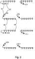
- FIGs 1 and 2 illustrate an identical hypothetical survey site. Forty-eight geophones in eight geophone strings are arrayed over the geographic area to be surveyed. In the prior art seismic system of Figure 1 , two wireless digital recorders 3 are used to record twenty-four geophones each. Eight digitizing modules 2 are located in proximity with the geophone strings for converting the low level analog geophone signals to multiplexed digital data, which is in turn telemetered over cables 4 to the more centrally-located wireless digital recorders 3. In contrast, according to a preferred embodiment of the invention and as shown in Figure 2 , eight wireless digital recorders 10, one for each geophone string 16, 18, are employed. The wireless digital recorders 10 include digitizing circuitry therein and are miniaturized to promote rapid and efficient deployment of the seismic system. In operation, a large number of seismic recorders 10 with associated geophone strings 16 are positioned across the geographical area to be surveyed. Recorder 10 is a simple "place and forget" device that is usually set to record continuously for many days during which the surveys are conducted.
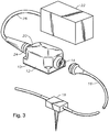
- FIG. 3 illustrates a digital seismic recorder 10 according to a preferred embodiment of the invention.
- Seismic recorder 10 is housed in a lightweight sealed case 12 designed to withstand expected environmental conditions.
- Case 12 includes an input connector 14 for connecting one or more strings 16 of geophones 18 (only one geophone is shown).
- seismic recorder 10 includes one or more input channels for connecting one or more seismic sensors at input connector 14. Strings 16 of sensors 18 are well understood by one skilled in the art and are not discussed further herein.
- Case 12 includes a combination battery/data connector 20.
- Figure 3 shows an extended-life battery 22 plugged into the battery/data connector 20 by plug 24 and power cable 26 for providing power to seismic recorder 10 during operation in the field.
- Battery 22 is preferably a 12 to 15 volt battery. Because battery 22 is located externally of seismic recorder 10, the operator can easily vary the capacity of the battery to provide power for various survey durations. That is, a higher volt-ampere capacity battery provides for longer operation in the field and/or longer recording time.
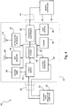
- FIG. 4 is a functional block diagram showing the internal structure of stand-alone digital seismic recorder 10.
- the major components of seismic recorder 10 are a power supply module 32, a processing system 34, an acquisition electronics module 36, an Ethernet interface 38, a memory 40, an RF operator interface 42, and a global positioning system (GPS) satellite receiver 44.
- a power supply module 32 a processing system 34, an acquisition electronics module 36, an Ethernet interface 38, a memory 40, an RF operator interface 42, and a global positioning system (GPS) satellite receiver 44.
- GPS global positioning system
- Seismic recorder 10 measures the seismic sensor 18 signal(s), converts the measurements to digital data, and stores the data in non-volatile internal memory 40. Synchronized time signals are recorded to time stamp the seismic data, so no centralized triggering is required to control the start of a recording cycle.
- a large memory 40 preferably enables up to thirty days of seismic data to be stored for a number of geophone channels.
- a system timer 54 with real time clock may be used to turn on or turn off the recording function, or the operator may turn on or turn off the recording function using an RF operator interface 42. Alternatively, system timer 54 may interface directly with power supply 32 for completely turning on and off all of the remaining electronics of recorder 10.
- seismic data is collected from recorders 10 during array relocation after the survey is complete and all required data has been collected.
- Battery 22 is disconnected from battery/data connector 20, and a data collection computer 30 is connected to battery/data connector 20 for downloading the collected data from the internal memory 40 of seismic recorder 10.
- the data collection computer 30 supplies power to seismic recorder 10 while the data are being extracted.
- the discharged battery 22 is exchanged for a freshly recharged battery 22, and the digital seismic recorder 10 is moved to a new survey location.
- Seismic Recorder 10 is powered by battery 22 at battery/data connector 20, which drives a power supply module 32 for supplying power to the other components of seismic recorder 10.
- Geophones 18 do not require electrical power to operate.
- power supply module 32 supplies power to each components only when power is needed by that component.
- the processing system 34 controls the overall operation of seismic recorder 10.
- Processing system 34 interfaces with the acquisition electronics module 36, Ethernet interface 38, memory 40, RF operator interface 42, and GPS receiver 44, preferably via one or more buses or electrical connections 35.
- Processing system 34 may interface with GPS receiver 44 using National Marine Electronics Association (NMEA) 0183 or 2000 protocols, for example.
- NMEA National Marine Electronics Association
- the processing system preferably includes a central processing unit (CPU) 50, an acquisition clock module 52, and control logic for interfacing with the other components of recorder 10.
- CPU central processing unit
- acquisition clock module 52 an acquisition clock module
- control logic for interfacing with the other components of recorder 10.
- CPU 50 is preferably an ARM7 processor with integrated peripherals.
- the ARM7 processor is a 32-bit reduced instruction set computer (RISC) microprocessor that is designed for use in low-power mobile devices such as cellular telephones. Arm Limited licenses the ARM7 processor for manufacture by a number of semiconductor companies. However, other processors may be used.
- RISC reduced instruction set computer
- CPU 50 transfers digitized seismic data from the acquisition electronics module 36 and stores the data in the memory 40.
- CPU 50 also controls the power to each component in order to save power when the components are not being used.
- Acquisition clock module 52 is used to provide synchronized time among all of the many digital seismic recorders 10 used in a seismic survey. Time stamps based on acquisition clock module 52 are periodically recorded in memory 40 along with the seismic data. As described below, the accuracy of acquisition clock module 52 is periodically tested and then adjusted by CPU 50 using the derived time signal output of GPS receiver 44 as the time standard. Acquisition clock module 52 is preferably composed of a digital-to-analog converter (DAC) driving a voltage-controlled temperature-compensated crystal oscillator (VCTCXO). The output of the oscillator is divided down and phase locked by a phase-locked loop (PLL) to 1 pulse per second (“pps"). The loop filter algorithm of the PLL is computed by CPU 50. However, other timing circuits may be used as appropriate.
- DAC digital-to-analog converter
- VTCXO voltage-controlled temperature-compensated crystal oscillator
- PLL phase-locked loop
- pps pulse per second
- the loop filter algorithm of the PLL is computed by CPU 50.
- acquisition electronics module 36 is a single or multi-channel digitizer for receiving and converting a number of analog geophone signals.
- the digitizer preferably includes a preamplifier and a high-dynamic-range 24-bit analog-to-digital converter (ADC) capable of digitizing the seismic signals at various sample rates and gains. More preferably, the ADC is delta-sigma type having a modulator, digital low-pass filter, and decimation filter.
- Acquisition electronics module 36 may also include a DAC for producing test signals.
- recorder 10 is described as including an ADC for digitizing the analog signals provided by conventional geophones, accelerometers, or geophoneaccelerometers, for example, the recorder may also be used with digital seismic sensors. In this case, the ADC would not be necessary, and processing system 34 would employ an all-digital interface with the digital sensors for recording the seismic data in memory 40.
- System timer 54 is a is low-power clock circuit similar to one found in a wrist watch having timer and alarm functionality. System timer 54 is used to turn on (awake) and off (asleep) digital seismic recorder 10 or its recording function according to a preset schedule, for example, turning off recorder 10 during nights, weekends and holidays to conserve battery 22 reserves and memory 40 capacity. Turn-on and turn-off times and dates are ideally programmed into a memory, for example, a memory integral with system timer 54 or non-volatile memory 40. System timer 54 may be designed and arranged to be set with the time and date from the GPS receiver 44 whenever battery 22 is first connected.
- Ethernet interface 38 is connected to processing system 34 for downloading seismic data from memory 40 to data collection computer 30 and to upload set-up and recording parameters to memory 40.
- data port types may be used, such as a universal serial bus (USB), Firewire, or Bluetooth, for example.
- Ethernet interface 38 preferably provides an external connection at battery/data connector 20.
- Memory 40 is connected to processing system 34 for storing the seismic data output by acquisition electronics module 36 and associated time information from acquisition clock module 52, until the data are downloaded to data collection computer 30 via Ethernet interface 38.
- Memory 40 is preferably non-volatile and of a sufficient capacity for storing seismic data for long periods of time. For example, 4 Gbytes per seismic channel may allow up to 30 days of continuous sampling.
- a Secure Digital card commonly known as a SD card or SD memory, is a flash memory card about the size of a postage stamp commonly used for digital cameras, which features high security, speedy data transfer, good storage capacity, and ruggedness. Ideally, a SD card is employed for memory 40. However, other memory devices may be used.
- RF operator interface 42 provides a radio frequency link for operator control of seismic recorder 10 and for setup and testing during deployment.
- RF operator interface 42 is preferably a low-power radio transceiver which operates within a range of 100 meters.
- An internal RF antenna 43 may be provided within case 12. As RF systems are well known to those skilled in the art, RF operator interface 42 is not described in detail.
- GPS receiver 44 is a high-sensitivity receiver that is designed to receive signals from the constellation of GPS satellites.
- An internal antenna 45 is ideally provided within case 12. Inclusion of satellite antenna 45 inside the case 12 eliminates the need for an antenna amplifier between antenna 45 and receiver 44, which in turn reduces the power requirements of seismic recorder 10 and battery 22.
- Receiver antenna 45 is optimally located on the same printed circuit board as receiver 44.
- Each GPS satellite has an extremely accurate onboard atomic clock and broadcasts a 50 bit per second navigation message.
- There is only one possible receiver clock signal a clock signal that is in perfect synchronism with the GPS time held by the atomic clocks in the GPS satellites that results in trilateration of the received navigation signals from four or more GPS satellites to a single point in space.
- Receiver 44 calculates this clock signal, referred to herein as the receiver-derived GPS time.
- GPS receiver preferably includes a local receiver clock circuit (typically 1 pps). Once GPS receiver 44 has acquired and is tracking four or more satellite signals, receiver 44 calculates GPS time and sets the local receiver clock to the receiver-derived GPS time (or to a receiver-derived UTC time, as described below). GPS receiver 44 is used to adjust acquisition clock module 52 to the derived satellite time standard, so that time-stamped data recorded by each of the individual seismic recorders 10 can be synchronistically analyzed.
- a local receiver clock circuit typically 1 pps
- acquisition clock module 52 is left to count independently without adjustment, and GPS receiver 44 is temporarily turned off for an adaptive period of time based on past clock accuracy and perceived temperature drift. This is accomplished by processing system 34 ceasing to update the crystal oscillator and turning off receiver 44. The receiver can be left in operation continuously if it is desired, but this increases the power consumption.
- a temperature sensor 80 may be provided for measuring temperature drift.
- the sampling accuracy of seismic signals is affected by the drift in acquisition clock 52 frequency, and the quality of sub-surface image may be adversely affected by significant timing variations of signal sampling.
- acquisition clock 52 may slowly drift from the 1 pps frequency and lose synchronicity with the time standard.
- temperature compensated clock circuits minimize frequency drift, drift cannot be completely eliminated. Therefore, according to a preferred embodiment, clock frequency drift and timing are maintained within predetermined limits by turning off power to satellite receivers for an adaptive amount of time, depending on the rate of drift. At a later time, timing lock is reestablished by processing system 34 turning on receiver 44, waiting until receiver 44 has derived the satellite time standard, recording the time error, then allowing the PLL to correct the timing error in acquisition clock module 52.
- Control algorithms within recorder 10 maintain timing error within limits by adapting the amount of time the satellite receiver is turned off.
- the control algorithms primarily rely on the measured drift of acquisition clock 52 during the period the satellite receiver was turned off, but other variables, such as temperature change, may be used as input variables.
- Various algorithms known to those skilled in the art may be implemented for adapting the adjustment duty cycle.
- Recorder 10 is preferably programmed with default timing error limits.
- GPS time to which the atomic clocks on the GPS satellites are set, is not synchronized with Coordinated Universal Time (UTC) or International Atomic Time (TAI), because GPS time is not corrected (with leap seconds, for example) to match the rotation of the earth.
- the GPS navigation messages include an almanac component, which is used by most commercial off-the-shelf GPS receivers to relate the receiver-derived GPS time to UTC.
- Either GPS time or UTC may be used as the time standard for synchronizing digital recorders 10, as long as use is consistent among the recorders. However, because it takes over twelve minutes to for the GPS system to broadcast the complete almanac (which is used by receiver 44 to relate GPS time to UTC), it is preferable that each recorder 10 synchronize acquisition clock 52 to receiver-derived GPS time, instead of receiver-derived UTC. The use of GPS time may shorten the receiver initialization time, thus saving power during the clock adjustment cycles.
- receiver-derived UTC time is used to set acquisition clock modules 52, it is preferred that almanac data is stored in memory (either non-volatile memory 40, or a dedicated non-volatile or battery powered CMOS memory within GPS receiver 44, for example) during the GPS receiver off periods, so that receiver initialization time will be minimized.
- memory either non-volatile memory 40, or a dedicated non-volatile or battery powered CMOS memory within GPS receiver 44, for example
- UTC as the time standard may be preferable if receiver 44 is implemented with a commercial off-the-shelf receiver that does not provide a means for accessing the raw receiver-derived GPS time.
- GPS receiver 44 is described as including a local receiver clock, which is independent of acquisition clock 52. This arrangement is preferred when using off-the-shelf integrated GPS receiver chips that include an onboard clock whose operation cannot be controlled independently of the GPS receiver function.
- the GPS receiver local clock and acquisition clock module 52 are one and the same, and GPS receiver 44 can be made to selectively update the clock at the command of processor 50 and be idled or de-energized when not in use without otherwise affecting the clock.
- Digital seismic recorder 10 ideally includes several other power saving features:
- Another feature of recorder 10 is the ability to detect a failure in the clock circuit.
- Each recorder 10 of the many deployed in a survey independently adjusts its acquisition clock 52 to the satellite time standard.
- Each recorder 10 will have unique drift characteristics resulting in different adjustment duty cycles. Recorders 10 with acquisition clocks 52 that drift faster than others will turn on their satellite receivers 44 more often than others to keep the sampling error within allowable limits.
- the time intervals over which the GPS receivers 44 are turned on and off and the temperature changes, et cetera, are recorded in memory 44.
- an algorithm in data collection computer 30 is used to detect those recorders 10 that have acquisition clock circuits 52 which have had high drift rates. In this manner, offending recorder circuits can be easily identified for repair.
Landscapes
- Physics & Mathematics (AREA)
- Life Sciences & Earth Sciences (AREA)
- Engineering & Computer Science (AREA)
- Remote Sensing (AREA)
- General Life Sciences & Earth Sciences (AREA)
- General Physics & Mathematics (AREA)
- Geophysics (AREA)
- Acoustics & Sound (AREA)
- Environmental & Geological Engineering (AREA)
- Geology (AREA)
- Geophysics And Detection Of Objects (AREA)
- Recording Measured Values (AREA)
Description
- This invention relates generally to a seismic systems, and more particularly to seismic systems used in the hydrocarbon exploration and mining industries.
- Terrestrial seismic data acquisition systems are well known in the art. An array of geophones are positioned across a geographical region, typically in a grid pattern, for measuring seismic vibrations. The precise location of each geophone must be known and is typically ascertained by a separate positioning survey. A seismic vibration source is activated, and the geophone measurements are recorded, sometimes over a period of several hours to several days or weeks, collected, and subsequently processed to determine the structure of the earth at that geographical region.
- In many seismic systems, multi-channel digital recorders are connected to a number of input geophone channels for sampling and converting the analog geophone outputs to digital format, which are recorded. It is often preferred that the analog-to-digital conversion occurs in the field close to the geophones to minimize degradation of the low-level geophone signals.
- It is necessary to ensure that all of the numerous digitized seismic channels can be precisely correlated to a common time standard for analysis. Sampling time errors result in wrong sets of data being analyzed for each instant of time and are perceived as noise. The noise created by sample timing mismatch is both time and frequency dependent, because the errors created depend on the slew rate of the signal at each sample instant. Large timing errors cause binning problems in depth point processing and result in significant depth errors.
- In many prior art seismic recording systems, the seismic channel data are analyzed strictly according to their sequential sampling order, and timing errors are minimized by ensuring simultaneous triggering of all recorders to begin sampling. Triggering the digital recorders may be performed by hard-wired or wireless radio frequency (RF) control.
- In hard-wired systems, control and power are provided by cabling that connects the digital recorders to a control interface. This type of system has an additional advantage of having a conductive signal path to transmit seismic data from the numerous digital recorders for central collection, typically at a control vehicle. However, the cabling is heavy, and weight is a significant cost in deploying a seismic system. Also, the cables are subject to damage by being crushed under passing vehicles or being chewed by rodents and livestock, for example.
- In wireless systems, the weight of the cabling between digital recorders is eliminated, but the weight savings is offset by batteries used to power the digital recorders and RF receivers used for triggering wireless systems. Wireless systems also typically employ RF transmitters in the digital recorders for transmitting seismic data to a central location for collection and processing. Large wireless seismic survey systems require a significant amount of RF bandwidth and a fairly large antenna at the control vehicle. Radio wave propagation paths may be obstructed by terrain, vegetation or structures. Furthermore, battery life limits the time a system may remain in the field, even in standby conditions, and creates logistical difficulties in deploying large seismic system arrays.
-
Figure 1 illustrates a "wireless" seismic recording system of prior art in which strings of geophones (1) are connected to multi-channel digitizer modules (2), for example, six geophones per string and four channels per recorder. Because of the low-level signals produced by analog sensors, the digitizer modules (2) are each located in close proximity to their attached geophones. The digitizer modules (2) include preamplifiers and analog-to-digital converters to digitize the geophone signals into digital data. The seismic digital data are then in turn transmitted by the digitizer modules to a data acquisition module (3) via electrical cabling (4). Depending on the telemetry techniques employed, the data acquisition modules (3) may be located a significant distance away from the digitizer modules (2). - In a given survey, a number of data acquisition modules (3) are used, each having its own corresponding digitizer modules (2) and geophone strings (1) to form an independent cell within the wireless system. Two such cells are represented in
Figure 1 . Each data acquisition module contains memory for recording the digital seismic data from its corresponding family of digitizer modules, and the data acquisition module supplies power, control, and synchronized clock signals to the digitizer modules. Each data acquisition module has a battery, and it may also include a radio frequency transmitter for broadcasting collected seismic data to a control vehicle, for example. Timing synchronization is maintained between the geophone channels by including a global positioning receiver within each data acquisition module (3). Each data acquisition module (3) continuously processes satellite navigation data to provide a common time standard among the units. Other prior art seismic systems, for example,U.S. Patent No. 5,978,313 issued to Longaker ,U.S. Patent No. 7,269,095 issued to Chamberlain et al. , andU.S. Patent Publication No. 2008/0021658 in the name of Pavel et al. , disclose seismic systems that employ satellite navigation system receivers for establishing synchronization among the recording units, but no provision is made for idling the satellite receiver to conserve power. - As the price of oil has increased and the cost of computer processing power has decreased, it is desirable to increase the number of geophones or other sensors used in a survey to cover larger areas and provide higher resolution surveys. For a three dimensional survey, many thousands of geophones or other sensors may be deployed at intervals often exceeding 100 yards (91.44 m) or more. Synchronization, power management, and deployment of digital recorders on this scale can be problematic. Although the data acquisition modules of the system of
Figure 1 are wireless, a large amount of cabling (4), with its inherent disadvantages, is still required between the data acquisition modules (3) and the digitizer modules (2). A wireless system of energy-efficient, high-capacity digital recorders collocated near the geophones with the digitizing circuitry would advantageously reduce the amount of cabling required. -
US 2004/0105533 discloses a seismic data acquisition apparatus having a recorder co-located with a sensor unit, and a communication device for direct communication with a central recorder. A GPS receiver may be provided to provide location parameters such as position and location data for correlating seismic information and for synchronizing data acquisition. -
US 5,864,315 discloses a direct sequence spread spectrum signal processing system which permits the receiver to be turned off during most of the acquisition phase of reception to reduce the on time of the associated receiver front end. - A primary object of the invention is to provide a seismic data acquisition system including field-deployable digital recorders for capturing seismic data that have integral satellite receivers for synchronizing the timing between recorded seismic data from multiple recorders, thus eliminating the cost of deploying traditional timing/triggering systems.
- Another object of the invention is to provide a wireless seismic acquisition system wherein the digital recorders are collocated with digitizing electronics near the analog sensors, thus minimizing the volume, weight and cost of cable to deploy and maintain.
- Another object of the invention is to provide a wireless digital seismic recorder with an independent acquisition clock circuit that is used to sample and to time stamp recorded seismic data and a satellite receiver that is activated only periodically to adjust the acquisition clock circuit. By not continuously processing satellite navigation signals, power requirements are reduced.
- Another object of the invention is to provide an intelligent digital seismic recorder that periodically adjusts a local acquisition clock circuit to a satellite time standard and that measures the acquisition clock drift and temperature changes and adjusts clock cycle times to maximize periods between synchronization while maintaining the acquisition clock circuit within a given error tolerance.
- Another object of the invention is to provide a seismic data acquisition system having field-deployable digital recorders that periodically record time stamps with seismic data and that are equipped with large non-volatile memories to eliminate the need for centralized triggering.
- Another object of the invention is to provide a seismic data acquisition system arranged for transferring recorded seismic data to collection computers in the field during surveys, after the data is collected.
- Another object of the invention is to provide a seismic data acquisition system having field-deployable digital recorders equipped with low-power-consumption electronics and that are designed and programmed to automatically and selectively de-energize or idle system components when not required for use, thus extending the usable time in field and reducing operating costs.
- Another object of the invention is to provide a seismic data acquisition system having field-deployable digital recorders which employ dynamic voltage control techniques to lower computer processor power consumption by idling the processor during periods of lower computational demands.
- According to one aspect of the present invention there is provided a recorder for recording seismic data as defined in
claim 1. - According to another aspect of the present invention there is provided a method for conducting a seismic survey as defined in
claim 10. - Preferred features of the invention are recited in the dependent claims.
- The objects described above and other advantages and features of the invention are, in a preferred embodiment, incorporated in a seismic recording system that includes cordless battery-operated digital seismic recorders. Each recorder is located with and adapted for connecting to one or more seismic sensors and for digitizing and recording single or multi-channel seismic data from the sensors. Rather than relying on the use of concurrent triggering to ensure multi-channel timing integrity, one or more time stamps are recorded with the digitized seismic data in non-volatile memory. Each recorder may commence recording independently of the others and includes memory of sufficient capacity to allow extended periods of operation.
- Each recorder includes its own acquisition clock, processing system, and global positioning system (GPS) receiver for the purpose of establishing synchronization of recorded seismic data among the many recorders typically required for a survey. The processing system is arranged for periodically synchronizing the acquisition clock to a satellite time standard derived by the GPS receiver.
- Each recorder preferably includes a low-power system timer that may be used to remotely turn on and off the recorders according to a pre-programmed schedule to conserve power when the system is not in use.
- Each recorder also preferably includes a wireless communications link for short range communication with a controller for programming or controlling the recorder in the field. Each recorder also ideally includes a hardwired data port for collecting seismic data and programming the recorder.
- The recorder employs low-power electronics and power management techniques. Electronic components are idled or de-energized when not needed.
- The invention includes a method for conducting a seismic survey that, according to a preferred embodiment, includes the steps of maintaining the acquisition clock of each recorder in synchronization with the satellite time standard by periodically adjusting the acquisition clock with the recorders' onboard GPS receiver. The satellite receiver is de-energized except when needed for the periodic adjustment of the acquisition clock.
- Each recorder tailors the acquisition clock adjustment periods based on measured acquisition clock timing errors and/or temperature drift (which affects the local acquisition clock period). These parameters are monitored by the processing system within each recorder. The processing system adapts the time between each adjustment to the maximum necessary to keep the local acquisition clock within a given tolerance to the satellite time standard. Because the GPS receiver is only periodically utilized, the method results in lowering the power requirements of the recorder.
- The invention is described in detail hereinafter on the basis of the embodiments represented in the accompanying figures, in which:
-
Figure 1 is a schematic diagram illustrating a prior art wireless seismic data acquisition system showing strings of geophones connected to digitizing modules, which are in turn connected by cabling to remote wireless digital recorders; -
Figure 2 is a schematic diagram illustrating a low-power satellite-timed seismic data acquisition system according to a preferred embodiment of the invention, showing strings of geophones directly connected to wireless digital recorders that are located in proximity to the geophone strings; -
Figure 3 is a perspective isometric drawing illustrating the basic components of the low-power satellite-timed seismic data acquisition system ofFigure 2 , showing a field-deployable digital seismic recorder in a sealed case, a partial string of geophones, and an external extended-life battery; -
Figure 4 is a block diagram schematic of the digital seismic recorder ofFigure 3 , showing a processing system, power supply, integral global positioning system receiver, data acquisition electronics, radio frequency operator interface, system timer, and Ethernet data port; and -
Figure 5 is a block diagram schematic of the processing system ofFigure 4 , showing a central processing unit, an acquisition clock module, and an optional intelligent energy manager. -
Figures 1 and2 illustrate an identical hypothetical survey site. Forty-eight geophones in eight geophone strings are arrayed over the geographic area to be surveyed. In the prior art seismic system ofFigure 1 , two wirelessdigital recorders 3 are used to record twenty-four geophones each. Eight digitizingmodules 2 are located in proximity with the geophone strings for converting the low level analog geophone signals to multiplexed digital data, which is in turn telemetered over cables 4 to the more centrally-located wirelessdigital recorders 3. In contrast, according to a preferred embodiment of the invention and as shown inFigure 2 , eight wirelessdigital recorders 10, one for eachgeophone string digital recorders 10 include digitizing circuitry therein and are miniaturized to promote rapid and efficient deployment of the seismic system. In operation, a large number ofseismic recorders 10 with associated geophone strings 16 are positioned across the geographical area to be surveyed.Recorder 10 is a simple "place and forget" device that is usually set to record continuously for many days during which the surveys are conducted. -
Figure 3 illustrates a digitalseismic recorder 10 according to a preferred embodiment of the invention.Seismic recorder 10 is housed in a lightweight sealedcase 12 designed to withstand expected environmental conditions.Case 12 includes aninput connector 14 for connecting one ormore strings 16 of geophones 18 (only one geophone is shown). Preferably,seismic recorder 10 includes one or more input channels for connecting one or more seismic sensors atinput connector 14.Strings 16 ofsensors 18 are well understood by one skilled in the art and are not discussed further herein.Case 12 includes a combination battery/data connector 20.Figure 3 shows an extended-life battery 22 plugged into the battery/data connector 20 byplug 24 andpower cable 26 for providing power toseismic recorder 10 during operation in the field.Battery 22 is preferably a 12 to 15 volt battery. Becausebattery 22 is located externally ofseismic recorder 10, the operator can easily vary the capacity of the battery to provide power for various survey durations. That is, a higher volt-ampere capacity battery provides for longer operation in the field and/or longer recording time. -
Figure 4 is a functional block diagram showing the internal structure of stand-alone digitalseismic recorder 10. The major components ofseismic recorder 10 are apower supply module 32, aprocessing system 34, anacquisition electronics module 36, anEthernet interface 38, amemory 40, anRF operator interface 42, and a global positioning system (GPS)satellite receiver 44. -
Seismic recorder 10 measures theseismic sensor 18 signal(s), converts the measurements to digital data, and stores the data in non-volatileinternal memory 40. Synchronized time signals are recorded to time stamp the seismic data, so no centralized triggering is required to control the start of a recording cycle. Alarge memory 40 preferably enables up to thirty days of seismic data to be stored for a number of geophone channels. For eachrecorder 10, asystem timer 54 with real time clock may be used to turn on or turn off the recording function, or the operator may turn on or turn off the recording function using anRF operator interface 42. Alternatively,system timer 54 may interface directly withpower supply 32 for completely turning on and off all of the remaining electronics ofrecorder 10. - According to the preferred embodiment of the invention, seismic data is collected from
recorders 10 during array relocation after the survey is complete and all required data has been collected.Battery 22 is disconnected from battery/data connector 20, and adata collection computer 30 is connected to battery/data connector 20 for downloading the collected data from theinternal memory 40 ofseismic recorder 10. Thedata collection computer 30 supplies power toseismic recorder 10 while the data are being extracted. The dischargedbattery 22 is exchanged for a freshly rechargedbattery 22, and the digitalseismic recorder 10 is moved to a new survey location. -
Seismic Recorder 10 is powered bybattery 22 at battery/data connector 20, which drives apower supply module 32 for supplying power to the other components ofseismic recorder 10.Geophones 18 do not require electrical power to operate. As illustrated inFigure 5 , in an embodiment where anintelligent energy manager 60 is used,power supply module 32 supplies power to each components only when power is needed by that component. - The
processing system 34 controls the overall operation ofseismic recorder 10.Processing system 34 interfaces with theacquisition electronics module 36,Ethernet interface 38,memory 40,RF operator interface 42, andGPS receiver 44, preferably via one or more buses orelectrical connections 35.Processing system 34 may interface withGPS receiver 44 using National Marine Electronics Association (NMEA) 0183 or 2000 protocols, for example. As illustrated inFigure 5 , the processing system preferably includes a central processing unit (CPU) 50, anacquisition clock module 52, and control logic for interfacing with the other components ofrecorder 10. The art of interfacing CPUs with peripheral devices is well known to routineers and is therefore not described in detail herein. -
CPU 50 is preferably an ARM7 processor with integrated peripherals. The ARM7 processor is a 32-bit reduced instruction set computer (RISC) microprocessor that is designed for use in low-power mobile devices such as cellular telephones. Arm Limited licenses the ARM7 processor for manufacture by a number of semiconductor companies. However, other processors may be used.CPU 50 transfers digitized seismic data from theacquisition electronics module 36 and stores the data in thememory 40.CPU 50 also controls the power to each component in order to save power when the components are not being used. -
Acquisition clock module 52 is used to provide synchronized time among all of the many digitalseismic recorders 10 used in a seismic survey. Time stamps based onacquisition clock module 52 are periodically recorded inmemory 40 along with the seismic data. As described below, the accuracy ofacquisition clock module 52 is periodically tested and then adjusted byCPU 50 using the derived time signal output ofGPS receiver 44 as the time standard.Acquisition clock module 52 is preferably composed of a digital-to-analog converter (DAC) driving a voltage-controlled temperature-compensated crystal oscillator (VCTCXO). The output of the oscillator is divided down and phase locked by a phase-locked loop (PLL) to 1 pulse per second ("pps"). The loop filter algorithm of the PLL is computed byCPU 50. However, other timing circuits may be used as appropriate. - Referring back to
Figure 4 ,acquisition electronics module 36 is a single or multi-channel digitizer for receiving and converting a number of analog geophone signals. The digitizer preferably includes a preamplifier and a high-dynamic-range 24-bit analog-to-digital converter (ADC) capable of digitizing the seismic signals at various sample rates and gains. More preferably, the ADC is delta-sigma type having a modulator, digital low-pass filter, and decimation filter.Acquisition electronics module 36 may also include a DAC for producing test signals. - Although
recorder 10 is described as including an ADC for digitizing the analog signals provided by conventional geophones, accelerometers, or geophoneaccelerometers, for example, the recorder may also be used with digital seismic sensors. In this case, the ADC would not be necessary, andprocessing system 34 would employ an all-digital interface with the digital sensors for recording the seismic data inmemory 40. -
System timer 54 is a is low-power clock circuit similar to one found in a wrist watch having timer and alarm functionality.System timer 54 is used to turn on (awake) and off (asleep) digitalseismic recorder 10 or its recording function according to a preset schedule, for example, turning offrecorder 10 during nights, weekends and holidays to conservebattery 22 reserves andmemory 40 capacity. Turn-on and turn-off times and dates are ideally programmed into a memory, for example, a memory integral withsystem timer 54 ornon-volatile memory 40.System timer 54 may be designed and arranged to be set with the time and date from theGPS receiver 44 wheneverbattery 22 is first connected. - An
Ethernet interface 38 is connected to processingsystem 34 for downloading seismic data frommemory 40 todata collection computer 30 and to upload set-up and recording parameters tomemory 40. However, other data port types may be used, such as a universal serial bus (USB), Firewire, or Bluetooth, for example.Ethernet interface 38 preferably provides an external connection at battery/data connector 20. -
Memory 40 is connected to processingsystem 34 for storing the seismic data output byacquisition electronics module 36 and associated time information fromacquisition clock module 52, until the data are downloaded todata collection computer 30 viaEthernet interface 38.Memory 40 is preferably non-volatile and of a sufficient capacity for storing seismic data for long periods of time. For example, 4 Gbytes per seismic channel may allow up to 30 days of continuous sampling. A Secure Digital card, commonly known as a SD card or SD memory, is a flash memory card about the size of a postage stamp commonly used for digital cameras, which features high security, speedy data transfer, good storage capacity, and ruggedness. Ideally, a SD card is employed formemory 40. However, other memory devices may be used. -
RF operator interface 42 provides a radio frequency link for operator control ofseismic recorder 10 and for setup and testing during deployment.RF operator interface 42 is preferably a low-power radio transceiver which operates within a range of 100 meters. Aninternal RF antenna 43 may be provided withincase 12. As RF systems are well known to those skilled in the art,RF operator interface 42 is not described in detail. -
GPS receiver 44 is a high-sensitivity receiver that is designed to receive signals from the constellation of GPS satellites. Aninternal antenna 45 is ideally provided withincase 12. Inclusion ofsatellite antenna 45 inside thecase 12 eliminates the need for an antenna amplifier betweenantenna 45 andreceiver 44, which in turn reduces the power requirements ofseismic recorder 10 andbattery 22.Receiver antenna 45 is optimally located on the same printed circuit board asreceiver 44. - Each GPS satellite has an extremely accurate onboard atomic clock and broadcasts a 50 bit per second navigation message. There is only one possible receiver clock signal a clock signal that is in perfect synchronism with the GPS time held by the atomic clocks in the GPS satellites that results in trilateration of the received navigation signals from four or more GPS satellites to a single point in space.
Receiver 44 calculates this clock signal, referred to herein as the receiver-derived GPS time. - GPS receiver preferably includes a local receiver clock circuit (typically 1 pps). Once
GPS receiver 44 has acquired and is tracking four or more satellite signals,receiver 44 calculates GPS time and sets the local receiver clock to the receiver-derived GPS time (or to a receiver-derived UTC time, as described below).GPS receiver 44 is used to adjustacquisition clock module 52 to the derived satellite time standard, so that time-stamped data recorded by each of the individualseismic recorders 10 can be synchronistically analyzed. - Rather than continuously synchronizing
acquisition clock 52 to the GPS time insatellite receiver 44, after an adjustment event,acquisition clock module 52 is left to count independently without adjustment, andGPS receiver 44 is temporarily turned off for an adaptive period of time based on past clock accuracy and perceived temperature drift. This is accomplished by processingsystem 34 ceasing to update the crystal oscillator and turning offreceiver 44. The receiver can be left in operation continuously if it is desired, but this increases the power consumption. Atemperature sensor 80 may be provided for measuring temperature drift. - The sampling accuracy of seismic signals is affected by the drift in
acquisition clock 52 frequency, and the quality of sub-surface image may be adversely affected by significant timing variations of signal sampling. When counting independently,acquisition clock 52 may slowly drift from the 1 pps frequency and lose synchronicity with the time standard. Although temperature compensated clock circuits minimize frequency drift, drift cannot be completely eliminated. Therefore, according to a preferred embodiment, clock frequency drift and timing are maintained within predetermined limits by turning off power to satellite receivers for an adaptive amount of time, depending on the rate of drift. At a later time, timing lock is reestablished by processingsystem 34 turning onreceiver 44, waiting untilreceiver 44 has derived the satellite time standard, recording the time error, then allowing the PLL to correct the timing error inacquisition clock module 52. - Control algorithms within
recorder 10 maintain timing error within limits by adapting the amount of time the satellite receiver is turned off. The control algorithms primarily rely on the measured drift ofacquisition clock 52 during the period the satellite receiver was turned off, but other variables, such as temperature change, may be used as input variables. Various algorithms known to those skilled in the art may be implemented for adapting the adjustment duty cycle.Recorder 10 is preferably programmed with default timing error limits. - GPS time, to which the atomic clocks on the GPS satellites are set, is not synchronized with Coordinated Universal Time (UTC) or International Atomic Time (TAI), because GPS time is not corrected (with leap seconds, for example) to match the rotation of the earth. The GPS navigation messages include an almanac component, which is used by most commercial off-the-shelf GPS receivers to relate the receiver-derived GPS time to UTC.
- Either GPS time or UTC may be used as the time standard for synchronizing
digital recorders 10, as long as use is consistent among the recorders. However, because it takes over twelve minutes to for the GPS system to broadcast the complete almanac (which is used byreceiver 44 to relate GPS time to UTC), it is preferable that eachrecorder 10 synchronizeacquisition clock 52 to receiver-derived GPS time, instead of receiver-derived UTC. The use of GPS time may shorten the receiver initialization time, thus saving power during the clock adjustment cycles. If receiver-derived UTC time is used to setacquisition clock modules 52, it is preferred that almanac data is stored in memory (eithernon-volatile memory 40, or a dedicated non-volatile or battery powered CMOS memory withinGPS receiver 44, for example) during the GPS receiver off periods, so that receiver initialization time will be minimized. Use of UTC as the time standard may be preferable ifreceiver 44 is implemented with a commercial off-the-shelf receiver that does not provide a means for accessing the raw receiver-derived GPS time. -
GPS receiver 44 is described as including a local receiver clock, which is independent ofacquisition clock 52. This arrangement is preferred when using off-the-shelf integrated GPS receiver chips that include an onboard clock whose operation cannot be controlled independently of the GPS receiver function. However, in an alternate embodiment, the GPS receiver local clock andacquisition clock module 52 are one and the same, andGPS receiver 44 can be made to selectively update the clock at the command ofprocessor 50 and be idled or de-energized when not in use without otherwise affecting the clock. - Digital
seismic recorder 10 ideally includes several other power saving features: - First,
processing system 34 turns off any component that is not being used, even for short periods, to save power. Device interrupts may be used toflag processing system 34 to power up a component for a specific task. For example,acquisition electronics module 36 may hold output in a buffer; when the buffer is near full, an interrupt is sent toprocessing system 34 to turn on theSD memory 40, transfer the data from the buffer to thememory 40, and then turn offmemory 40 again. Other peripherals are powered in a similar manner. - Second,
CPU 50 is placed in a low-power idle mode each time it is not needed. In one embodiment, as illustrated inFigure 5 ,processing system 34 may optionally include an intelligent energy manager (IEM) 60, which is a combination of hardware and software designed to reduce power and energy consumption by using dynamic voltage control to de-energize all electronic components when they are not needed. - Another feature of
recorder 10 is the ability to detect a failure in the clock circuit. Eachrecorder 10 of the many deployed in a survey independently adjusts itsacquisition clock 52 to the satellite time standard. Eachrecorder 10 will have unique drift characteristics resulting in different adjustment duty cycles.Recorders 10 withacquisition clocks 52 that drift faster than others will turn on theirsatellite receivers 44 more often than others to keep the sampling error within allowable limits. The time intervals over which theGPS receivers 44 are turned on and off and the temperature changes, et cetera, are recorded inmemory 44. When data from therecorders 10 are collected, an algorithm indata collection computer 30 is used to detect thoserecorders 10 that haveacquisition clock circuits 52 which have had high drift rates. In this manner, offending recorder circuits can be easily identified for repair. - While some embodiments of the invention have been illustrated in detail, the invention is not limited to the embodiments shown; modifications and adaptations of the above embodiments may occur to those skilled in the art, within the scope of the invention as set forth in the claims.
Claims (13)
- A recorder (10) for recording seismic data comprising:a housing (12);a processor (50) disposed in said housing operatively coupled to at least one seismic sensor (18) for receiving data therefrom;a memory (40) disposed in said housing and operatively coupled to said processor for storing said data;an acquisition clock module (52) disposed in said housing and operatively coupled to said processor; anda satellite navigation system receiver (44) disposed in said housing and operatively coupled to said processor;wherein said processor (50) is arranged and designed to:idle said satellite navigation system receiver for a first duration; andperiodically adjust said acquisition clock module (52) with a time signal derived by said satellite navigation system receiver (44);characterised in that said processor (50) is arranged and designed further to measure a change in temperature by said recorderand determine said first duration as a function of said change in temperature;whereby synchronized timing between a plurality of said recorders is maintainable without continuous operation of said satellite navigation system receiver of each of said recorders.
- The recorder (10) of claim 1 further comprising:
an analog-to-digital converter (36) operatively coupled to said processor and arranged to be operatively coupled to said at least one seismic sensor (18) for receiving an analog signal therefrom. - A recorder (10) according to claim 2 for digitizing and recording geophone seismic signals wherein said analog-to-digital converter (36) is disposed in said housing, and is arranged to convert said analog signal to digital data.
- The recorder (10) of any of the preceding claims, further comprising a power supply circuit (32) connected to said processor for supplying electrical power thereto.
- The recorder of claim 4 further comprising:an electrical connector (20) forming a part of said housing;a power conductor connected between said power supply circuit and said electrical connector; anda data interface port (38) operatively coupled said processor and terminating at said electrical connector;whereby said electrical connector is designed and arranged to be connected to a device from the group consisting of a computer (30) and a battery (22).
- The recorder (10) of claim 4 or 5, further comprising a programmable clock timer (54) operatively coupled to said power supply for energizing and de-energizing said recorder according to a preset schedule.
- The recorder of any of claims 4 to 6, wherein said power supply circuit is arranged for supplying power for functional activity.
- The recorder of any of claims 4 to 7, wherein said power supply circuit (32) is for supplying electrical power to the processor as a function of processor activity.
- The recorder of any of the preceding claims further comprising:
a radio frequency transceiver (42) operatively coupled to said processor. - A method for conducting a seismic survey comprising the steps of:providing a plurality of recorders (10) each housing a processor (50), a memory (40), a satellite navigation system receiver (44), and an acquisition clock circuit (52), each of said plurality of recorders being operatively coupled to at least one seismic sensor (18) for receiving seismic information therefrom; andfor each of said plurality of recorders, disposing said recorder in a survey site, recording a time stamp of said acquisition clock circuit in said memory, and recording said seismic information in said memory;for each of said plurality of recorders:periodically determining a time standard by said satellite navigation system receiver;periodically adjusting said acquisition clock circuit to said time standard;idling said satellite navigation system receiver for a first duration when said satellite navigation system receiver is not determining said time standard;characterised by measuring a change in temperature by said recorder; anddetermining said first duration as a function of said change in temperature;whereby synchronized timing between said plurality of recorders is maintainable without continuous operation of said satellite navigation system receivers of each of said recorders.
- The method of claim 10 further comprising the steps of, for at least one of said plurality of recorders:measuring a time difference between said acquisition clock circuit and said time standard; anddetermining said first duration as a function of said time difference.
- The method of claim 10 or 11, further comprising the steps of, for at least one of said plurality of recorders:
providing a power supply (32) having the ability to supply power to components as a function of operational requirements. - The method of any of claims 10 to 12 further comprising the steps of, for at least one of said plurality of recorders:providing a timer (54);energizing said recorder by said timer; andde-energizing said recorder by said timer.
Applications Claiming Priority (2)
| Application Number | Priority Date | Filing Date | Title |
|---|---|---|---|
| US97426607P | 2007-09-21 | 2007-09-21 | |
| PCT/US2008/010904 WO2009038769A1 (en) | 2007-09-21 | 2008-09-19 | Low- power satellite-timed seismic data acquisition system |
Publications (3)
| Publication Number | Publication Date |
|---|---|
| EP2191300A1 EP2191300A1 (en) | 2010-06-02 |
| EP2191300A4 EP2191300A4 (en) | 2017-07-12 |
| EP2191300B1 true EP2191300B1 (en) | 2020-02-12 |
Family
ID=40468226
Family Applications (1)
| Application Number | Title | Priority Date | Filing Date |
|---|---|---|---|
| EP08831527.0A Active EP2191300B1 (en) | 2007-09-21 | 2008-09-19 | Low- power satellite-timed seismic data acquisition system |
Country Status (4)
| Country | Link |
|---|---|
| US (2) | US8898019B2 (en) |
| EP (1) | EP2191300B1 (en) |
| CA (2) | CA2919647C (en) |
| WO (1) | WO2009038769A1 (en) |
Families Citing this family (25)
| Publication number | Priority date | Publication date | Assignee | Title |
|---|---|---|---|---|
| US8605543B2 (en) | 2007-09-21 | 2013-12-10 | Fairfield Industries Incorporated | Method and apparatus for correcting the timing function in a nodal seismic data acquisition unit |
| CA2996790C (en) | 2007-09-21 | 2022-03-08 | Fairfield Industries, Inc. | Method and apparatus for correcting the timing function in a nodal seismic data acquisition unit |
| US8296067B2 (en) * | 2008-03-17 | 2012-10-23 | Bp Corporation North America Inc. | Satellite communications with cableless seismographs |
| US9529102B2 (en) | 2010-04-30 | 2016-12-27 | Conocophillips Company | Caterpillar-style seismic data acquisition using autonomous, continuously recording seismic data recorders |
| US20120008460A1 (en) * | 2010-07-12 | 2012-01-12 | Wireless Seismic | Data acquisition system with removable |
| US8781045B2 (en) * | 2010-09-02 | 2014-07-15 | Mediatek Inc. | Communication apparatuses and wireless communications modules |
| US9134456B2 (en) * | 2010-11-23 | 2015-09-15 | Conocophillips Company | Electrical methods seismic interface box |
| WO2012082471A1 (en) * | 2010-12-14 | 2012-06-21 | Conocophillips Company | Autonomous electrical methods node |
| US9133699B2 (en) | 2010-12-15 | 2015-09-15 | Conocophillips Company | Electrical methods fracture detection via 4D techniques |
| WO2012094134A1 (en) | 2011-01-05 | 2012-07-12 | Conocophillips Company | Fracture detection via self-potential methods with an electrically reactive proppant |
| EP2677346A1 (en) * | 2012-06-19 | 2013-12-25 | Sercel | Digital seismic sensor and acquisition device adapted to be connected together via a two-conductor line. |
| NO336544B1 (en) * | 2012-08-16 | 2015-09-21 | Magseis As | Autonomous seabed seismic node comprising a reference oscillator |
| TWI572320B (en) | 2014-07-22 | 2017-03-01 | Automatic elastic expansion of vertebral implants | |
| US11487871B2 (en) * | 2015-01-31 | 2022-11-01 | San Diego Gas & Electric Company | Methods and systems for detecting and defending against invalid time signals |
| CN106052846A (en) * | 2016-05-27 | 2016-10-26 | 山东科技大学 | Portable intrinsic safety type vibration signal collection device and vibration information collection method |
| US10509434B1 (en) * | 2016-09-27 | 2019-12-17 | Amazon Technologies, Inc. | Oscillator profiling for time synchronization |
| CN106405635B (en) * | 2016-11-01 | 2019-02-15 | 中国科学院声学研究所 | A kind of Multi-channel data acquisition synchronization system |
| US10310110B2 (en) | 2017-02-21 | 2019-06-04 | Geospace Technologies Corporation | Systems and methods for seismic data acquisition |
| CN107728210B (en) * | 2017-10-27 | 2019-07-09 | 中国石油天然气集团公司 | Multiple instruments acquire the determination method and apparatus that road is lacked in data |
| CN108923878B (en) * | 2018-09-14 | 2024-03-22 | 扬州英迈克测控技术有限公司 | Sensor node based on WiFi wireless and GPS time service synchronization |
| CN109557577A (en) * | 2019-01-16 | 2019-04-02 | 合肥国为电子有限公司 | Suitable for the seismographic clock-generating device of node and method |
| GB201914919D0 (en) * | 2019-10-15 | 2019-11-27 | Bp Exploration Operating Co Ltd | Clock drift |
| DE102019220495A1 (en) | 2019-12-20 | 2021-06-24 | Continental Automotive Gmbh | Procedure for checking the validity of sensor data in an on-board Ethernet network |
| CN113156849B (en) * | 2021-03-17 | 2023-03-24 | 上海极熵数据科技有限公司 | Industrial equipment data acquisition method and system and storage medium |
| CN113534242A (en) * | 2021-07-15 | 2021-10-22 | 南方海洋科学与工程广东省实验室(广州) | Microseism observation data acquisition method, device, equipment and storage medium |
Family Cites Families (66)
| Publication number | Priority date | Publication date | Assignee | Title |
|---|---|---|---|---|
| US449063A (en) * | 1891-03-24 | Speed-controlling device | ||
| US3748638A (en) * | 1971-11-08 | 1973-07-24 | Shell Oil Co | Seismic exploration system |
| US4493063A (en) | 1978-10-30 | 1985-01-08 | Phillips Petroleum Company | Method and apparatus for seismic geophysical exploration |
| US4281403A (en) * | 1979-09-12 | 1981-07-28 | Litton Resources Systems, Inc. | Seismic data recording method and apparatus |
| US4589100A (en) * | 1981-10-30 | 1986-05-13 | Western Geophysical Company Of America | Method and apparatus for positioning seismic arrays |
| US4809005A (en) | 1982-03-01 | 1989-02-28 | Western Atlas International, Inc. | Multi-antenna gas receiver for seismic survey vessels |
| US7164117B2 (en) * | 1992-05-05 | 2007-01-16 | Automotive Technologies International, Inc. | Vehicular restraint system control system and method using multiple optical imagers |
| DE3381322D1 (en) | 1982-12-29 | 1990-04-19 | Amoco Corp | METHOD AND DEVICE FOR CONTROLLING WIRELESS SEISMIC DIGITAL RECORDER CAPABLE OF TREATING SEISMAL DATA. |
| US4725992A (en) * | 1985-12-03 | 1988-02-16 | Amoco Corporation | Adaptive seismometer group recorder having enhanced operating capabilities |
| US4879696A (en) * | 1986-03-27 | 1989-11-07 | Exxon Production Research Company | Method and apparatus for initiating seismic data storage in an isolated distributed recording system |
| US4800538A (en) * | 1986-03-31 | 1989-01-24 | Refraction Technology, Inc. | Method of and systems for seismic exploration |
| FR2666946B1 (en) * | 1990-09-17 | 1992-12-04 | Inst Francais Du Petrole | METHOD AND DEVICE FOR SYNCHRONIZING ON AN EXTERNAL EVENT THE SAMPLING OF MEASUREMENT SIGNALS BY AN OVER-SAMPLING TYPE SCANNING ASSEMBLY. |
| US5243469A (en) * | 1990-11-14 | 1993-09-07 | Union Oil Company Of California | System for the acquisition of seismic data |
| CA2091962A1 (en) * | 1992-03-31 | 1993-10-01 | Mark L. Witsaman | Clock synchronization system |
| NO176860C (en) * | 1992-06-30 | 1995-06-07 | Geco As | Method for synchronizing systems for seismic surveys, as well as applications of the method |
| US5650981A (en) * | 1993-01-06 | 1997-07-22 | Precision Seismic, Inc. | Multi-vessel timing synchronization method and device |
| US5510797A (en) * | 1993-04-15 | 1996-04-23 | Trimble Navigation Limited | Provision of SPS timing signals |
| US5629626A (en) * | 1994-07-12 | 1997-05-13 | Geo-Centers, Inc. | Apparatus and method for measuring buried ferromagnetic objects with a high accuracy of position and in synchronization with a sync pulse provided by a global positioning system |
| US5754449A (en) * | 1995-04-25 | 1998-05-19 | Instrumented Sensor Technology, Inc. | Method and apparatus for recording time history data of physical variables |
| US5724241A (en) * | 1996-01-11 | 1998-03-03 | Western Atlas International, Inc. | Distributed seismic data-gathering system |
| AUPO264996A0 (en) | 1996-09-27 | 1996-10-24 | Martin Communications Pty Ltd | Event recording and analysis in telecommunication networks |
| CA2268939C (en) * | 1996-10-23 | 2006-08-01 | Vibration Technology Limited | Seismic acquisition system using wireless telemetry |
| US5864315A (en) | 1997-04-07 | 1999-01-26 | General Electric Company | Very low power high accuracy time and frequency circuits in GPS based tracking units |
| US6002640A (en) * | 1997-05-15 | 1999-12-14 | Geo-X Systems, Inc. | Seismic data acquisition system |
| FR2766580B1 (en) * | 1997-07-24 | 2000-11-17 | Inst Francais Du Petrole | METHOD AND SYSTEM FOR TRANSMITTING SEISMIC DATA TO A REMOTE COLLECTION STATION |
| US5978313A (en) * | 1997-09-30 | 1999-11-02 | Trimble Navigaiton Limited | Time synchronization for seismic exploration system |
| GB9723189D0 (en) * | 1997-11-03 | 1998-01-07 | Wireless Systems Int Ltd | Apparatus for and method of synchronising oscillators within a data communication system |
| US6002339A (en) * | 1998-01-30 | 1999-12-14 | Western Atlas International, Inc. | Seismic synchronization system |
| US6226601B1 (en) * | 1998-05-15 | 2001-05-01 | Trimble Navigation Limited | Seismic survey system |
| US6188962B1 (en) * | 1998-06-25 | 2001-02-13 | Western Atlas International, Inc. | Continuous data seismic system |
| US20040105533A1 (en) * | 1998-08-07 | 2004-06-03 | Input/Output, Inc. | Single station wireless seismic data acquisition method and apparatus |
| FR2787201B1 (en) * | 1998-12-14 | 2001-01-12 | Inst Francais Du Petrole | METHOD AND DEVICE FOR SYNCHRONIZED ACQUISITION OF SEISMIC SIGNALS |
| FR2799004B1 (en) * | 1999-09-27 | 2001-10-19 | Inst Francais Du Petrole | TRANSMISSION METHOD AND SYSTEM USING A STANDARD TRANSMISSION NETWORK, TO CONNECT ELEMENTS OF A SEISMIC DEVICE |
| US6724319B1 (en) * | 1999-10-29 | 2004-04-20 | Litton Systems, Inc. | Acoustic sensing system for downhole seismic applications utilizing an array of fiber optic sensors |
| US6611724B1 (en) * | 1999-11-24 | 2003-08-26 | Square D Company | On line monitor for a control device |
| GB0004371D0 (en) * | 2000-02-24 | 2000-04-12 | Koninkl Philips Electronics Nv | GPS receiver and mobile unit incorporating the same |
| FR2808335B1 (en) * | 2000-04-28 | 2002-07-12 | Inst Francais Du Petrole | METHOD AND SYSTEM FOR SYNCHRONIZING ELEMENTS OF A SEISMIC DEVICE USING A STANDARD TRANSMISSION NETWORK AND AN EXTERNAL TIME REFERENCE |
| US6977867B2 (en) * | 2001-06-05 | 2005-12-20 | Geo-X Systems, Ltd. | Seismic data acquisition system |
| JP3499840B2 (en) | 2001-07-06 | 2004-02-23 | 白山工業株式会社 | Data collection system and method for geophysical exploration |
| JP3714891B2 (en) | 2001-07-12 | 2005-11-09 | 白山工業株式会社 | Apparatus and method for simultaneous recording of sensor signal and GPS time |
| JP2005504971A (en) * | 2001-10-02 | 2005-02-17 | サーフ テクノロジー インコーポレイテッド | Global positioning device and method for performing position determination using an oscillator with temperature compensation |
| CN1200285C (en) | 2001-11-09 | 2005-05-04 | 中国石油天然气集团公司 | GPS satellite time service telemetering seismograph |
| FR2833359B1 (en) * | 2001-12-10 | 2004-04-23 | Inst Francais Du Petrole | SEISMIC DATA ACQUISITION SYSTEM USING SEA-BASED ACQUISITION STATIONS |
| GB2388264A (en) * | 2002-01-10 | 2003-11-05 | Roke Manor Research | GPS based networked time synchronised unit |
| US7551057B2 (en) * | 2005-11-04 | 2009-06-23 | Lear Corporation | Remote entry system with increased transmit power and reduced quiescent current |
| US7298671B2 (en) * | 2002-04-24 | 2007-11-20 | Ascend Geo, Llc | Seismic-data acquisition methods and apparatus |
| US6934219B2 (en) * | 2002-04-24 | 2005-08-23 | Ascend Geo, Llc | Methods and systems for acquiring seismic data |
| US20060009911A1 (en) * | 2002-04-24 | 2006-01-12 | Ascend Geo, Llc | Methods and systems for acquiring and processing seismic data |
| AUPS306802A0 (en) * | 2002-06-20 | 2002-07-11 | Wmc Resources Ltd | A data acquisition unit, system and method for geophysical data |
| US6847587B2 (en) * | 2002-08-07 | 2005-01-25 | Frank K. Patterson | System and method for identifying and locating an acoustic event |
| FR2843805B1 (en) * | 2002-08-22 | 2004-12-17 | Inst Francais Du Petrole | METHOD AND DEVICE FOR ACQUISITION FOR SEISMIC EXPLORATION OF A GEOLOGICAL FORMATION BY PERMANENT RECEPTORS IMPLANTED AT THE BOTTOM OF THE SEA |
| US20050047275A1 (en) * | 2003-09-01 | 2005-03-03 | Geo-X Systems, Ltd. | Synchronization and positioning of seismic data acquisition systems |
| US7269095B2 (en) * | 2002-10-04 | 2007-09-11 | Aram Systems, Ltd. | Synchronization of seismic data acquisition systems |
| GB2395640B (en) * | 2002-11-22 | 2006-06-07 | Westerngeco Seismic Holdings | Implementing a network infrastructure in a seismic acquisition system |
| EP1623250B1 (en) * | 2003-04-18 | 2016-08-03 | Advanced Geosciences, Inc. | Techniques for surface exploration and monitoring |
| US7561493B2 (en) * | 2003-05-30 | 2009-07-14 | Fairfield Industries, Inc. | Method and apparatus for land based seismic data acquisition |
| US7117094B2 (en) * | 2003-07-17 | 2006-10-03 | Novatel, Inc. | Seismic measuring system including GPS receivers |
| US6928030B2 (en) * | 2003-08-30 | 2005-08-09 | Geo-X Systems, Ltd. | Seismic defense system |
| US7124028B2 (en) * | 2003-11-21 | 2006-10-17 | Fairfield Industries, Inc. | Method and system for transmission of seismic data |
| EP1700436B1 (en) * | 2004-02-24 | 2007-07-11 | Matsushita Electric Industrial Co., Ltd. | Terminal apparatus for enabling a plurality of different communication systems to coexist |
| US7551516B2 (en) * | 2005-03-09 | 2009-06-23 | Aram Systems, Ltd. | Vertical seismic profiling method utilizing seismic communication and synchronization |
| US7224642B1 (en) * | 2006-01-26 | 2007-05-29 | Tran Bao Q | Wireless sensor data processing systems |
| CA2654887A1 (en) * | 2006-06-09 | 2007-12-21 | Ion Geophysical Corporation | Operating state management for seismic data acquisition |
| CN101512532B (en) * | 2006-06-10 | 2012-02-15 | 爱诺华有限公司 | Apparatus and method for integrating survey parameters into a header |
| US7660201B2 (en) * | 2006-08-22 | 2010-02-09 | Autoseis, Inc. | Autonomous seismic data acquisition unit |
| WO2008042801A2 (en) * | 2006-09-29 | 2008-04-10 | Ion Geophysical Corporation | Configuration tool and methods for seismic data acquisition |
-
2008
- 2008-09-19 WO PCT/US2008/010904 patent/WO2009038769A1/en active Application Filing
- 2008-09-19 US US12/284,192 patent/US8898019B2/en active Active
- 2008-09-19 EP EP08831527.0A patent/EP2191300B1/en active Active
- 2008-09-19 CA CA2919647A patent/CA2919647C/en active Active
- 2008-09-19 CA CA2700163A patent/CA2700163C/en active Active
-
2014
- 2014-01-27 US US14/164,449 patent/US9255999B2/en active Active
Non-Patent Citations (1)
| Title |
|---|
| None * |
Also Published As
| Publication number | Publication date |
|---|---|
| WO2009038769A1 (en) | 2009-03-26 |
| US9255999B2 (en) | 2016-02-09 |
| CA2700163C (en) | 2016-03-29 |
| EP2191300A1 (en) | 2010-06-02 |
| CA2700163A1 (en) | 2009-03-26 |
| US20140142858A1 (en) | 2014-05-22 |
| US8898019B2 (en) | 2014-11-25 |
| CA2919647A1 (en) | 2009-03-26 |
| CA2919647C (en) | 2017-11-21 |
| US20100017139A1 (en) | 2010-01-21 |
| EP2191300A4 (en) | 2017-07-12 |
Similar Documents
| Publication | Publication Date | Title |
|---|---|---|
| EP2191300B1 (en) | Low- power satellite-timed seismic data acquisition system | |
| US10281613B2 (en) | Seismic data acquisition unit | |
| CA2741865C (en) | Practical autonomous seismic recorder implementation and use | |
| US11774613B2 (en) | Systems and methods for seismic data acquisition | |
| AU2021106916A4 (en) | Seismic data acquisition unit, method, and system employing the same | |
| CN103064109A (en) | Method and apparatus for correcting timing function in nodal seismic data acquisition unit | |
| US11327200B2 (en) | Seismic data acquisition unit | |
| JP3264350B2 (en) | Time generation device and method | |
| CN210038183U (en) | Channel wave seismic data acquisition system | |
| JP3856391B2 (en) | Time generating apparatus and method | |
| US11953636B2 (en) | Satellite-enabled node for ambient noise tomography | |
| JP2002107459A (en) | Data collecting system and method for geophysical exploration | |
| Sagaidachnya et al. | A Distributed Data Recording System as a Basis for Modern Seismic Research Technologies |
Legal Events
| Date | Code | Title | Description |
|---|---|---|---|
| PUAI | Public reference made under article 153(3) epc to a published international application that has entered the european phase |
Free format text: ORIGINAL CODE: 0009012 |
|
| 17P | Request for examination filed |
Effective date: 20100322 |
|
| AK | Designated contracting states |
Kind code of ref document: A1 Designated state(s): AT BE BG CH CY CZ DE DK EE ES FI FR GB GR HR HU IE IS IT LI LT LU LV MC MT NL NO PL PT RO SE SI SK TR |
|
| AX | Request for extension of the european patent |
Extension state: AL BA MK RS |
|
| DAX | Request for extension of the european patent (deleted) | ||
| RA4 | Supplementary search report drawn up and despatched (corrected) |
Effective date: 20170609 |
|
| RIC1 | Information provided on ipc code assigned before grant |
Ipc: G01V 11/00 20060101ALI20170602BHEP Ipc: G01V 1/16 20060101ALI20170602BHEP Ipc: G01V 1/22 20060101ALI20170602BHEP Ipc: G01V 1/00 20060101AFI20170602BHEP |
|
| GRAP | Despatch of communication of intention to grant a patent |
Free format text: ORIGINAL CODE: EPIDOSNIGR1 |
|
| STAA | Information on the status of an ep patent application or granted ep patent |
Free format text: STATUS: GRANT OF PATENT IS INTENDED |
|
| INTG | Intention to grant announced |
Effective date: 20190819 |
|
| GRAS | Grant fee paid |
Free format text: ORIGINAL CODE: EPIDOSNIGR3 |
|
| RAP1 | Party data changed (applicant data changed or rights of an application transferred) |
Owner name: GTC, INC. |
|
| GRAA | (expected) grant |
Free format text: ORIGINAL CODE: 0009210 |
|
| STAA | Information on the status of an ep patent application or granted ep patent |
Free format text: STATUS: THE PATENT HAS BEEN GRANTED |
|
| AK | Designated contracting states |
Kind code of ref document: B1 Designated state(s): AT BE BG CH CY CZ DE DK EE ES FI FR GB GR HR HU IE IS IT LI LT LU LV MC MT NL NO PL PT RO SE SI SK TR |
|
| REG | Reference to a national code |
Ref country code: GB Ref legal event code: FG4D |
|
| REG | Reference to a national code |
Ref country code: CH Ref legal event code: EP |
|
| REG | Reference to a national code |
Ref country code: AT Ref legal event code: REF Ref document number: 1232879 Country of ref document: AT Kind code of ref document: T Effective date: 20200215 |
|
| REG | Reference to a national code |
Ref country code: DE Ref legal event code: R096 Ref document number: 602008062122 Country of ref document: DE |
|
| REG | Reference to a national code |
Ref country code: IE Ref legal event code: FG4D |
|
| REG | Reference to a national code |
Ref country code: NO Ref legal event code: T2 Effective date: 20200212 |
|
| PG25 | Lapsed in a contracting state [announced via postgrant information from national office to epo] |
Ref country code: FI Free format text: LAPSE BECAUSE OF FAILURE TO SUBMIT A TRANSLATION OF THE DESCRIPTION OR TO PAY THE FEE WITHIN THE PRESCRIBED TIME-LIMIT Effective date: 20200212 |
|
| REG | Reference to a national code |
Ref country code: LT Ref legal event code: MG4D |
|
| REG | Reference to a national code |
Ref country code: NL Ref legal event code: MP Effective date: 20200212 |
|
| PG25 | Lapsed in a contracting state [announced via postgrant information from national office to epo] |
Ref country code: HR Free format text: LAPSE BECAUSE OF FAILURE TO SUBMIT A TRANSLATION OF THE DESCRIPTION OR TO PAY THE FEE WITHIN THE PRESCRIBED TIME-LIMIT Effective date: 20200212 Ref country code: BG Free format text: LAPSE BECAUSE OF FAILURE TO SUBMIT A TRANSLATION OF THE DESCRIPTION OR TO PAY THE FEE WITHIN THE PRESCRIBED TIME-LIMIT Effective date: 20200512 Ref country code: GR Free format text: LAPSE BECAUSE OF FAILURE TO SUBMIT A TRANSLATION OF THE DESCRIPTION OR TO PAY THE FEE WITHIN THE PRESCRIBED TIME-LIMIT Effective date: 20200513 Ref country code: SE Free format text: LAPSE BECAUSE OF FAILURE TO SUBMIT A TRANSLATION OF THE DESCRIPTION OR TO PAY THE FEE WITHIN THE PRESCRIBED TIME-LIMIT Effective date: 20200212 Ref country code: LV Free format text: LAPSE BECAUSE OF FAILURE TO SUBMIT A TRANSLATION OF THE DESCRIPTION OR TO PAY THE FEE WITHIN THE PRESCRIBED TIME-LIMIT Effective date: 20200212 Ref country code: IS Free format text: LAPSE BECAUSE OF FAILURE TO SUBMIT A TRANSLATION OF THE DESCRIPTION OR TO PAY THE FEE WITHIN THE PRESCRIBED TIME-LIMIT Effective date: 20200612 |
|
| PG25 | Lapsed in a contracting state [announced via postgrant information from national office to epo] |
Ref country code: NL Free format text: LAPSE BECAUSE OF FAILURE TO SUBMIT A TRANSLATION OF THE DESCRIPTION OR TO PAY THE FEE WITHIN THE PRESCRIBED TIME-LIMIT Effective date: 20200212 |
|
| PG25 | Lapsed in a contracting state [announced via postgrant information from national office to epo] |
Ref country code: CZ Free format text: LAPSE BECAUSE OF FAILURE TO SUBMIT A TRANSLATION OF THE DESCRIPTION OR TO PAY THE FEE WITHIN THE PRESCRIBED TIME-LIMIT Effective date: 20200212 Ref country code: SK Free format text: LAPSE BECAUSE OF FAILURE TO SUBMIT A TRANSLATION OF THE DESCRIPTION OR TO PAY THE FEE WITHIN THE PRESCRIBED TIME-LIMIT Effective date: 20200212 Ref country code: RO Free format text: LAPSE BECAUSE OF FAILURE TO SUBMIT A TRANSLATION OF THE DESCRIPTION OR TO PAY THE FEE WITHIN THE PRESCRIBED TIME-LIMIT Effective date: 20200212 Ref country code: EE Free format text: LAPSE BECAUSE OF FAILURE TO SUBMIT A TRANSLATION OF THE DESCRIPTION OR TO PAY THE FEE WITHIN THE PRESCRIBED TIME-LIMIT Effective date: 20200212 Ref country code: DK Free format text: LAPSE BECAUSE OF FAILURE TO SUBMIT A TRANSLATION OF THE DESCRIPTION OR TO PAY THE FEE WITHIN THE PRESCRIBED TIME-LIMIT Effective date: 20200212 Ref country code: LT Free format text: LAPSE BECAUSE OF FAILURE TO SUBMIT A TRANSLATION OF THE DESCRIPTION OR TO PAY THE FEE WITHIN THE PRESCRIBED TIME-LIMIT Effective date: 20200212 Ref country code: ES Free format text: LAPSE BECAUSE OF FAILURE TO SUBMIT A TRANSLATION OF THE DESCRIPTION OR TO PAY THE FEE WITHIN THE PRESCRIBED TIME-LIMIT Effective date: 20200212 Ref country code: PT Free format text: LAPSE BECAUSE OF FAILURE TO SUBMIT A TRANSLATION OF THE DESCRIPTION OR TO PAY THE FEE WITHIN THE PRESCRIBED TIME-LIMIT Effective date: 20200705 |
|
| REG | Reference to a national code |
Ref country code: DE Ref legal event code: R097 Ref document number: 602008062122 Country of ref document: DE |
|
| REG | Reference to a national code |
Ref country code: AT Ref legal event code: MK05 Ref document number: 1232879 Country of ref document: AT Kind code of ref document: T Effective date: 20200212 |
|
| PLBE | No opposition filed within time limit |
Free format text: ORIGINAL CODE: 0009261 |
|
| STAA | Information on the status of an ep patent application or granted ep patent |
Free format text: STATUS: NO OPPOSITION FILED WITHIN TIME LIMIT |
|
| 26N | No opposition filed |
Effective date: 20201113 |
|
| PG25 | Lapsed in a contracting state [announced via postgrant information from national office to epo] |
Ref country code: IT Free format text: LAPSE BECAUSE OF FAILURE TO SUBMIT A TRANSLATION OF THE DESCRIPTION OR TO PAY THE FEE WITHIN THE PRESCRIBED TIME-LIMIT Effective date: 20200212 Ref country code: AT Free format text: LAPSE BECAUSE OF FAILURE TO SUBMIT A TRANSLATION OF THE DESCRIPTION OR TO PAY THE FEE WITHIN THE PRESCRIBED TIME-LIMIT Effective date: 20200212 |
|
| PG25 | Lapsed in a contracting state [announced via postgrant information from national office to epo] |
Ref country code: PL Free format text: LAPSE BECAUSE OF FAILURE TO SUBMIT A TRANSLATION OF THE DESCRIPTION OR TO PAY THE FEE WITHIN THE PRESCRIBED TIME-LIMIT Effective date: 20200212 Ref country code: SI Free format text: LAPSE BECAUSE OF FAILURE TO SUBMIT A TRANSLATION OF THE DESCRIPTION OR TO PAY THE FEE WITHIN THE PRESCRIBED TIME-LIMIT Effective date: 20200212 |
|
| REG | Reference to a national code |
Ref country code: DE Ref legal event code: R119 Ref document number: 602008062122 Country of ref document: DE |
|
| PG25 | Lapsed in a contracting state [announced via postgrant information from national office to epo] |
Ref country code: MC Free format text: LAPSE BECAUSE OF FAILURE TO SUBMIT A TRANSLATION OF THE DESCRIPTION OR TO PAY THE FEE WITHIN THE PRESCRIBED TIME-LIMIT Effective date: 20200212 |
|
| REG | Reference to a national code |
Ref country code: CH Ref legal event code: PL |
|
| REG | Reference to a national code |
Ref country code: BE Ref legal event code: MM Effective date: 20200930 |
|
| PG25 | Lapsed in a contracting state [announced via postgrant information from national office to epo] |
Ref country code: LU Free format text: LAPSE BECAUSE OF NON-PAYMENT OF DUE FEES Effective date: 20200919 |
|
| PG25 | Lapsed in a contracting state [announced via postgrant information from national office to epo] |
Ref country code: DE Free format text: LAPSE BECAUSE OF NON-PAYMENT OF DUE FEES Effective date: 20210401 |
|
| PG25 | Lapsed in a contracting state [announced via postgrant information from national office to epo] |
Ref country code: CH Free format text: LAPSE BECAUSE OF NON-PAYMENT OF DUE FEES Effective date: 20200930 Ref country code: BE Free format text: LAPSE BECAUSE OF NON-PAYMENT OF DUE FEES Effective date: 20200930 Ref country code: LI Free format text: LAPSE BECAUSE OF NON-PAYMENT OF DUE FEES Effective date: 20200930 Ref country code: IE Free format text: LAPSE BECAUSE OF NON-PAYMENT OF DUE FEES Effective date: 20200919 |
|
| PG25 | Lapsed in a contracting state [announced via postgrant information from national office to epo] |
Ref country code: TR Free format text: LAPSE BECAUSE OF FAILURE TO SUBMIT A TRANSLATION OF THE DESCRIPTION OR TO PAY THE FEE WITHIN THE PRESCRIBED TIME-LIMIT Effective date: 20200212 Ref country code: MT Free format text: LAPSE BECAUSE OF FAILURE TO SUBMIT A TRANSLATION OF THE DESCRIPTION OR TO PAY THE FEE WITHIN THE PRESCRIBED TIME-LIMIT Effective date: 20200212 Ref country code: CY Free format text: LAPSE BECAUSE OF FAILURE TO SUBMIT A TRANSLATION OF THE DESCRIPTION OR TO PAY THE FEE WITHIN THE PRESCRIBED TIME-LIMIT Effective date: 20200212 |
|
| P01 | Opt-out of the competence of the unified patent court (upc) registered |
Effective date: 20230518 |
|
| PGFP | Annual fee paid to national office [announced via postgrant information from national office to epo] |
Ref country code: NO Payment date: 20230911 Year of fee payment: 16 Ref country code: GB Payment date: 20230727 Year of fee payment: 16 |
|
| PGFP | Annual fee paid to national office [announced via postgrant information from national office to epo] |
Ref country code: FR Payment date: 20230710 Year of fee payment: 16 |