EP2191148B1 - Vacuum generator device and method for operating the same - Google Patents
Vacuum generator device and method for operating the same Download PDFInfo
- Publication number
- EP2191148B1 EP2191148B1 EP08865808.3A EP08865808A EP2191148B1 EP 2191148 B1 EP2191148 B1 EP 2191148B1 EP 08865808 A EP08865808 A EP 08865808A EP 2191148 B1 EP2191148 B1 EP 2191148B1
- Authority
- EP
- European Patent Office
- Prior art keywords
- time
- pressure
- evacuation
- suction
- venting
- Prior art date
- Legal status (The legal status is an assumption and is not a legal conclusion. Google has not performed a legal analysis and makes no representation as to the accuracy of the status listed.)
- Active
Links
- 238000000034 method Methods 0.000 title claims description 30
- 238000013022 venting Methods 0.000 claims description 24
- 230000008569 process Effects 0.000 claims description 8
- 230000009467 reduction Effects 0.000 claims description 7
- 238000002347 injection Methods 0.000 claims description 3
- 239000007924 injection Substances 0.000 claims description 3
- 230000003287 optical effect Effects 0.000 claims description 3
- 238000012935 Averaging Methods 0.000 claims description 2
- 238000009423 ventilation Methods 0.000 description 34
- 238000005273 aeration Methods 0.000 description 32
- 238000001514 detection method Methods 0.000 description 11
- 238000012544 monitoring process Methods 0.000 description 11
- 230000006870 function Effects 0.000 description 7
- 238000004891 communication Methods 0.000 description 5
- 238000010586 diagram Methods 0.000 description 4
- 238000011156 evaluation Methods 0.000 description 4
- 238000010926 purge Methods 0.000 description 4
- 230000008859 change Effects 0.000 description 3
- 238000000151 deposition Methods 0.000 description 3
- 230000000694 effects Effects 0.000 description 3
- 230000007257 malfunction Effects 0.000 description 3
- 230000015556 catabolic process Effects 0.000 description 2
- 238000011109 contamination Methods 0.000 description 2
- 230000002950 deficient Effects 0.000 description 2
- 238000006731 degradation reaction Methods 0.000 description 2
- 230000003111 delayed effect Effects 0.000 description 2
- 238000013461 design Methods 0.000 description 2
- 239000012530 fluid Substances 0.000 description 2
- 238000005259 measurement Methods 0.000 description 2
- 238000012545 processing Methods 0.000 description 2
- 230000004044 response Effects 0.000 description 2
- 230000008054 signal transmission Effects 0.000 description 2
- 230000004913 activation Effects 0.000 description 1
- 230000005540 biological transmission Effects 0.000 description 1
- 238000009530 blood pressure measurement Methods 0.000 description 1
- 230000007423 decrease Effects 0.000 description 1
- 230000001419 dependent effect Effects 0.000 description 1
- 238000011161 development Methods 0.000 description 1
- 230000018109 developmental process Effects 0.000 description 1
- 238000003745 diagnosis Methods 0.000 description 1
- 238000006073 displacement reaction Methods 0.000 description 1
- 238000005516 engineering process Methods 0.000 description 1
- 239000012535 impurity Substances 0.000 description 1
- 238000012806 monitoring device Methods 0.000 description 1
- 238000004806 packaging method and process Methods 0.000 description 1
- 230000003584 silencer Effects 0.000 description 1
- 230000003797 telogen phase Effects 0.000 description 1
- 230000036962 time dependent Effects 0.000 description 1
Images
Classifications
-
- F—MECHANICAL ENGINEERING; LIGHTING; HEATING; WEAPONS; BLASTING
- F04—POSITIVE - DISPLACEMENT MACHINES FOR LIQUIDS; PUMPS FOR LIQUIDS OR ELASTIC FLUIDS
- F04F—PUMPING OF FLUID BY DIRECT CONTACT OF ANOTHER FLUID OR BY USING INERTIA OF FLUID TO BE PUMPED; SIPHONS
- F04F5/00—Jet pumps, i.e. devices in which flow is induced by pressure drop caused by velocity of another fluid flow
- F04F5/44—Component parts, details, or accessories not provided for in, or of interest apart from, groups F04F5/02 - F04F5/42
- F04F5/48—Control
- F04F5/52—Control of evacuating pumps
Definitions
- the invention relates to a method for operating a vacuum generator device which has an ejector device whose inlet is connected to an air supply channel and the suction side with a suction channel connected to a suction cup, and which has a pressure detecting device for detecting the pressure prevailing in the suction channel, wherein in the suction channel during an evacuation phase, starting from the atmospheric pressure, a sufficient working negative pressure is built up for holding an object through the suction gripper, and during a subsequent aeration phase, a release of the previously sucked-in object causing negative pressure reduction is caused.
- the invention further relates to a vacuum generator device having an ejector device which has an inlet connected to an air supply channel and has a suction opening, to which a suction channel is connected, which is connected or connectable to a suction gripper, and with a for detecting the prevailing in the suction channel Pressure-serving pressure detection device, and with control electronics to such control of the pressurization of the suction channel, that during an evacuation phase, starting from the atmospheric pressure for holding an object sufficient vacuum can be built up by the vacuum gripper and, during a subsequent ventilation phase, a releasing of the previously sucked-in object causing negative pressure reduction can be caused.
- the known vacuum generator device comprises an ejector device whose inlet can be connected via an air supply channel to a compressed air source in order to generate a negative pressure on a suction opening defining a suction side.
- the negative pressure is also applied to a connected suction channel which is connected or connectable to a suction gripper, by means of which an object to be handled can be held and transported by means of negative pressure.
- the working vacuum required to hold an object is established in an evacuation phase in which the inlet of the ejector device is supplied with compressed air.
- the negative pressure is reduced to an atmospheric pressure or up to an overpressure in a ventilation phase which adjoins the evacuation phase with a time interval. This happens in connection with a shutdown of the ejector.
- the known vacuum generator device includes a monitoring device for detecting the number of control operations that are performed between the evacuation phase and the aeration phase to keep the working negative pressure constant within a certain range. This allows some monitoring of the performance of the vacuum generator device. In particular, it is possible to draw conclusions as to whether an increased leakage occurs and consequently whether there are system faults.
- From the DE 10 2004 047 853 A1 shows a control device for a suction element, which has a device for generating negative pressure and contains an electronic module which is in operative connection with a separate display and / or operating device.
- the electronic module is used to monitor parameters such as evacuation and ventilation times and transmits the measured parameters to the display and / or operator panel.
- the DE 42 29 834 C2 describes a method and apparatus for electrically processing vacuum pressure information, comparing measured to stored pressure values, and then making an error determination.
- the US 5,617,898 discloses an array of fluid pressure devices, each having its own electronic control unit to relieve a connected sequencer.
- the fluid pressure devices may include displays to indicate malfunctions.
- the present invention has for its object to propose measures that enable a functional monitoring of a vacuum generating device.
- This object is achieved in a method of the type mentioned in that the evacuation in the evacuation phase to build up the working negative pressure evacuation time and / or in the ventilation phase until reaching a release of the previously held article associated ventilation pressure passing ventilation time is detected and compared with at least one predetermined reference time value to produce an electrical diagnostic signal in response to the comparison result, wherein one generates the at least one reference time value within the scope of a teaching process, whereby several work cycles containing at least one evacuation phase and / or at least one aeration phase are processed and the evacuation times (t E ) and / or ventilation times (t B ) occurring are determined, wherein the thus determined measured time values are derived, the reference time values, for example by averaging.
- control electronics has time recording means by the evacuation in the evacuation phase to build up the working negative pressure evacuation time and / or in the ventilation phase until reaching a release of the previously recorded object associated ventilation pressure elapsing ventilation time is detected
- control electronics also has comparator means by which the detected evacuation and / or ventilation time with at least one stored in memory means reference time value is comparable, and that the control electronics has output means, depending on the Comparison result of the comparator means can output an electrical diagnostic signal.
- the vacuum generating device is equipped to perform either only monitoring the evacuation phase or only monitoring the ventilation phase, although it is expediently designed such that both phases can be monitored.
- the reference time value or values are determined by a learning process. This can be done, for example, by alternately operating the vacuum generator device alternately in the evacuation phase and the aeration phase and detecting the evacuation times and ventilation times that occur in the process, which are then evaluated later to determine the respective reference time value.
- the evaluation may consist in determining an average value.
- the thus determined reference time values can be visualized by the vacuum generator device. It may also be possible to manually change these values to suit individual requirements.
- the evacuation time is measured with the help of the pressure detection device connected to the suction channel, which elapses until the build-up of the working negative pressure, expediently starting from the previously applied Atmospheric pressure and in particular beginning with an activation of the ejector device.
- the aeration time is measured, which elapses until the vacuum prevailing in the suction channel has dropped from the region of the working negative pressure to a venting pressure which is associated with a release of the previously sucked-in article.
- the aeration pressure used for the time comparison is expediently a pressure in the presence of which it can be assumed that a previously held object was normally released again.
- the venting pressure may correspond directly to the atmospheric pressure, but is conveniently a slight safety pressure below the atmospheric pressure, which allows for a more accurate measurement because the venting characteristic may be very shallow towards the atmospheric pressure, especially when operating without the ejector pulse. In an operation with ejection pulse, so if the release of the object is supported by a controlled by a blow-off overpressure pulse, the venting pressure may also be an overpressure.
- At least one time value based on empirical values can be stored as the reference time value, with which the detected evacuation time and / or aeration time are comparable, in order then to generate an electrical diagnostic signal depending on the result of the comparison, which gives the user indications of the current functional state or directly himself or causes a plurality of measures, for example, the output of an optical and / or acoustic warning message or the direct output of an operable by an external electronic control device electrical signal.
- the evacuation phase and the aeration phase are each assigned at least one own reference time value.
- the switch-off time of the ejector device and / or the time of an active air injection into the suction channel is possible to use the switch-off time of the ejector device and / or the time of an active air injection into the suction channel as starting time for the detection of the ventilation time.
- a respective diagnostic signal is generated if the detected evacuation time or ventilation time is above the respectively assigned reference time value.
- the diagnostic signal can be visualized directly on site at the vacuum generator device. If the vacuum generator device is connected to an external electronic control device, a diagnostic signal can also be output to this external control device.
- a plurality of different reference time values for the evacuation time and / or for the ventilation time can be stored at the same time, wherein the output electrical diagnostic signal depends on which of the stored reference time values corresponds to the respectively detected time. Accordingly, diagnostic signals can be generated at different diagnostic levels where different follow-up actions are taken. Thus, for example, only a warning signal can be emitted at a lower diagnostic level without impairing the function of the vacuum generator device. If the time difference increases and the system thereby enters a higher diagnostic level, drastic measures can be taken, up to a switch to continuous suction operation or a controlled shutdown of the device.
- the ejector device remains in operation even after reaching the working negative pressure in order to produce a constant suction effect in the suction channel.
- the working negative pressure used for the time comparison may be below the maximum actual negative pressure actually achievable.
- the ejector device is switched off when a working negative pressure is reached.
- a pertinent provision is expediently provided that in time sequence is always evacuated until reaching the desired working negative pressure when the negative pressure falls below a certain threshold.
- a check valve is turned on, which prevents unwanted degradation of the negative pressure in the located between the check valve and the suction pad system section with the ejector device.
- the Druck conductedseinruchtung detected here expediently the negative pressure in the extending between the check valve and the suction pad portion of the suction channel.
- the aeration phase can be initiated by shutting off the ejector device. If necessary, a blow-off valve can be activated simultaneously with the switching off of the ejector device in order to actively blow pressurized air under atmospheric pressure into the suction channel and to assist in depositing a previously aspirated object by means of an overpressure pulse denominated as a discharge pulse.
- the reference time values for the evacuation time and / or the aeration time can be entered by the user of the device itself.
- the vacuum generator device expediently contains suitable input means.
- control electronics of the vacuum generator device responsible for the evaluation is expediently an internal component of a vacuum generator unit which also contains the ejector device.
- an air filter is expediently switched on.
- monitoring means for monitoring the degree of filter contamination are present. Their function is based in particular on an evaluation of the differential pressure of the prevailing pressure before and after the air filter.
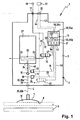
- the vacuum generator device serves the purpose of temporarily holding articles 5 by means of negative pressure so that they can be repositioned between different locations. It is used, for example, in assembly technology or in the packaging industry.
- FIG. 1 is exemplified as an object 5 illustrates a plate-shaped product.
- the vacuum generator device 1 contains a vacuum generator unit 2, to which at least one suction gripper 7 is connected.
- the vacuum generator device 1 can also be equipped with a plurality of vacuum generator units 2, which can also be combined to form an assembly.
- the suction gripper 7 is connected via a suction line 4 to the vacuum generator unit 2. In this case, it can be arranged away from the vacuum generator unit 2. However, it is also possible to arrange the suction gripper 7 directly on the vacuum generator unit 2, so that a rigid assembly is present.
- the suction gripper 7 is an example of a suction cup or suction cup. It limits a suction opening 12 having a working opening 8 and can be displaced in such a way that it comes into contact with its work opening 8 ahead of the object 5 to be handled. At the moment of investment the work opening 8 is covered by the article 5 and the suction chamber 12 is closed to the atmosphere.
- the displacement of the suction pad 7 is done by shifting a device supporting it, which may be the vacuum generator unit 2 itself when it is attached thereto.
- an air supply interface 17 which serves for the supply of compressed air, which is provided by an external compressed air source 18.
- an electromechanical communication interface 22 on the main housing 3 for the exchange of electrical signals and for the supply of the electrical energy required for the operation of the electrical components of the vacuum generator unit 2.
- an in FIG. 1 schematically indicated external electronic control device 23 are connected.
- the vacuum required for gripping an article 5 is generated directly in the vacuum generator unit 2.
- This is for this purpose equipped with at least one ejector 27, which includes at least one operating according to the ejector principle suction nozzle 26, the inlet 29 is connected via an air supply channel 32 to the air supply interface 17 and thus to the compressed air source 18.
- the ejector device 27 also has an outlet 33 leading to the atmosphere, to which a silencer can be connected if required.
- the ejector device 27 has a suction side or suction opening 34, which is connected via a suction channel 35 to the suction chamber 12 of the suction gripper 7.
- the suction channel 35 extends with a first channel section 35a inside the main housing 3, wherein it extends from the suction opening 34 to a suction line interface 6 arranged outside the main housing 3. At the latter, the already mentioned suction line 4 is connected, in which the suction channel 35 continues with a channel section 35b to the suction chamber 12.
- an electrically actuated control valve 36 is turned on, which conveniently has a 2/2-way functionality. It may selectively shut off or release the passage of air through the air supply passage 32 to thereby selectively shut off or turn on the air supply to the inlet 29 of the ejector means 27.
- blow-off channel 38 Another air supply channel, which is designated for better distinction as a blow-off channel 38 and which is optionally present, also communicates with the air supply interface 17 at one end and is connected to the suction channel 35 at a connection point 28 at the other end. If the outlet channel 38 is present, in turn an electrically actuable control valve is turned on, that is designated for better distinction as a blow-off valve 37. It is preferably of the same type as the already mentioned control valve 36 and may optionally occupy one of two positions in which it either shuts off or releases the passage of air through the exhaust passage 38.
- a dotted only indicated check valve 42 may be turned on. It is mainly used when the vacuum generator device 1 is equipped with an air-saving function. While the purge valve 37 with exhaust passage 38 may be present regardless of the presence of a check valve 42, the presence of the check valve 42 presupposes the presence of the purge passage 38 and the associated purge valve 37.
- the check valve 42 is oriented so that it allows an air flow from the suction pad 7 toward the ejector 27, but prevented in the opposite direction. In other words, it assumes a shut-off position when the pending on the side of the ejector 27 pressure is absolutely greater than the pending on the side of the suction pad 7 pressure.
- the check valve 42 is seated in that portion of the suction channel 35 which extends between the suction port 34 and the connection point 28.
- the vacuum generator device 1 has a pressure detection device 24. This allows a detection of the pressure prevailing in the suction channel 35 pressure and consequently also the negative pressure prevailing therein.
- the pressure detection device 24 is a pressure sensor which converts the pneumatic pressure into electrical pressure signals and feeds them to the vacuum generator unit 2 via a signal line 25, indicated by dashed lines, of an internal electronic control device designated below as control electronics 14.
- the pressure detection device 24 is preferably connected directly to the suction channel 35.
- the designated connection point 30 is located between the possibly existing check valve 42 and the suction pad 7, preferably at the first channel portion 35a.
- control valve 36 and the possibly existing blow-off valve 37 are expediently solenoid valves, although it is also conceivable to design them as piezo valves. Appropriately, they are of the type "normally closed”, so that they occupy the shut-off the associated channel closed position in the electrically non-actuated state. However, they could also be of the "normally open” type, and in particular the control valve 36 can also be designed as a bistable valve (impulse valve).
- Their control signals receive the control valve 36 and the blow-off valve 37 via at least one electrical control line 47, 48, by which they are connected to the already mentioned control electronics 14. Via the control lines 47, 48 can also be transmitted from the valves 36, 37 diagnostic signals to the control electronics 14, when the valves 36, 37 are equipped with means for their function monitoring.
- Such monitoring means may be, for example, means which monitor the switching position of the respective valve. Furthermore, it can be detected by the monitoring means, for example, when an EEPROM is defective, when there is undervoltage or a short circuit, when the solenoid is burned out or when the solenoid does not switch.
- an air filter 10 is expediently switched on, which frees the sucked air from impurities.
- This air filter 10 expediently associated monitoring means 11 which monitor the degree of filter contamination.
- the operating principle of the monitoring means 11 is based on a differential pressure measurement, based on the pressure difference, which is determined by the pressure sensing device 24 arranged on one side of the air filter and a pressure sensor 13 arranged on the other side of the air filter 10.
- the electrical pressure signals are transmitted via the already mentioned signal line 25 and a further signal line 15 to the control electronics 14 and evaluated by this.
- the pressure drop across the air filter is a measure of the pollution and can be used to output a signal indicating the need for a filter change.
- the control electronics 14 is connected via at least one signal transmission line 43 and expediently also at least one energy transmission line 44 transmitting the electrical energy with the communication interface 22 and can communicate in this way with the external electronic control device 23.
- the dot-dash line indicated, sucked object 5 is held by the vacuum generated in response to the evacuation of the suction chamber 12.
- the vacuum can be canceled by ventilating the suction chamber 12 again.
- the latter is done in the embodiment solely by switching off the ejector 27 by shutting off the inlet 29 of the compressed air source 18 by means of the switched into the closed position control valve 36.
- the suction chamber 12 is then on the suction passage 35 and the suction port 34th and the outlet 33 in the atmosphere and is consequently ventilated.
- the ventilation can be assisted by this blow-off valve 37 or carried out alone.
- a sole venting through the purge valve 37 takes place when the check valve 42 is present.
- pressurized air flows under pressurized air, causing the discharge valve 37 to open at the connection point 28 bypassing the ejector device 27 into the suction channel 35, so that the negative pressure is reduced very rapidly and under certain circumstances even at least for a short time Suction channel 35 prevails.
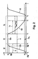
- FIG. 2 shown diagram, which reproduces the time-dependent course of the prevailing in the suction passage 35 at the junction 30 pressure p based on the curve 52 shown in a solid line.
- the zero point of the ordinate here corresponds to the atmospheric pressure, upwards the negative pressure is plotted.
- the diagram refers to a vacuum generator device 1 without a blow-off valve 37 and without a check valve 42.
- the suction gripper 7 with its work opening 8 is attached in advance to the object 5 and the ejector device 27 is switched on.
- the latter is done by switching on the air supply of the inlet 29 by the control valve 36 is switched to the open position. This starts a in FIG. 2 identified evacuation phase 62.
- a negative pressure gradually builds up in the suction channel 35 in accordance with a first curve section 52a, which increases until it has reached a working negative pressure p A after the lapse of an evacuation time t E at the time t 1 .
- This working negative pressure p A is sufficiently high to firmly suck the object to be transported 5 and securely hold.
- an intermediate phase 63 in which the ejector device 27 is still unchanged during operation, but the negative pressure does not increase any further or at least barely increases because of reaching the power limit of the ejector device 27.
- the negative pressure in the suction channel 35 thus remains substantially at the level of the working negative pressure p A , with a certain fluctuation range being permissible.
- the intermediate phase 63 may be a control phase in a vacuum-saving device 1 equipped with air-saving measures.
- the vacuum generator device 1 then contains the check valve 42 and the exhaust passage 38 with associated blow-off valve 37.
- the control phase provides that the control electronics 14, the ejector 27 at the time t 1 turns off, wherein the negative pressure in the suction channel 35 then still essentially remains, because the check valve 42 prevents degradation of the negative pressure.
- unavoidable leaks will nonetheless lead to a gradual reduction of the negative pressure, with the control electronics 14 re-operating the ejector means 27 when the pressure sensing means 24 detects excessive pressure reduction to a predetermined lower shift value.
- control electronics 14 integrated control means provide here for the desired pressure control and control of the components responsible for it, so that the working vacuum p A is maintained during the intermediate phase 63 within a limited by the lower switching value tolerance band. Since the ejector device 27 is only temporarily in operation in such an intermediate phase functioning as a control phase, compressed air and consequently energy are saved.
- the curve 52 has a substantially horizontal course in its second curve section 52b assigned to the intermediate phase 63.
- the time t 2 marks the end of the intermediate phase 63 and at the same time the beginning of a subsequent ventilation phase 64.
- the control valve 36 is switched by the control electronics 14 in the closed position, thereby deactivating the ejector 27. This condition is maintained throughout the ventilation phase 64. It has the consequence that the suction line 25 and thus the suction chamber 12 in the manner already mentioned via the outlet 33 of the Ejektor responded 27 is in communication with the atmosphere and consequently standing at atmospheric pressure air can flow into the suction line 35, which is referred to as aeration ,
- the elapsed between the time t 2 and the time t 4 time is in FIG. 2 marked by a double arrow and is referred to as the total aeration time t GB .
- the phases 62, 63, 64 thus define a total of one working cycle A, starting with the suction of an object 5, its subsequent holding and finally depositing the object.
- the intermediate phase 63 can be used to displace the suction gripper 7 with object 5 fixed thereto, in order to implement the object 5 between two places.
- a new evacuation phase can immediately follow again, or else a rest phase, which is used to position the suction gripper 7 closest to the object to be handled.
- the control electronics 14 is equipped with time detection means 51 which are capable of detecting both the above-mentioned evacuation time t E and, independently, an aeration time t B between the start time t 2 of the aeration phase and the attainment of a venting pressure p B passes.
- the start time for the detection of the evacuation time t E is expediently based on the switch-on time of the ejector device 27. In other words, here corresponds to the evacuation time t E of the time that elapses until the suction channel 35th has built up from the atmospheric pressure of the working vacuum p A.
- FIG. 2 In the diagram of FIG. 2 is shown as relevant for the time recording working vacuum p A of the maximum generated by the system vacuum. Deviating from this, however, a lower negative pressure, which is already sufficient to hold an object 5, can also be used as the working negative pressure p A. Such under the maximum producible negative pressure working vacuum p A is in FIG. 2 dash-dotted and drawn in parentheses. In this case, the time t 1 would move accordingly (also dash-dotted lines and indicated in parentheses).
- starting time for the detection of the aeration time t B in the embodiment of coinciding with the time t 2 shutdown of the ejector 27 is used. If a blow-off valve 37 were present, its switching into the open position and consequently the time of active air injection into the suction channel 35, ie the generation of a discharge pulse, could also be used as the starting time for the detection of the aeration time t B.
- the end time for the measurement of the aeration time t B may be the already mentioned time t 4 , in which the pressure in the suction channel 35 has risen to the atmospheric pressure.
- the aeration pressure p B then corresponds to the atmospheric pressure and the aeration time t B of the total aeration time t GB (the values for this are in FIG. 2 in brackets).
- pressure limit pressure limit
- This ventilation pressure p B modified by a safety factor with regard to the atmospheric pressure naturally already exists at an earlier point in time t 3 , so that accordingly the ventilation time t B to be detected is shorter than the total ventilation time t GB .
- the ventilation phase 64 is assisted by a blow-off valve 37, a faster reduction of the negative pressure results, and consequently a considerably steeper third curve section 52c.
- the total aeration time t GB can be used directly as the time duration t B to be compared with the reference time value.
- the time recording relevant ventilation pressure p B for example, also in the suction passage 35 adjusting, overlying the atmospheric pressure over pressure can be used.
- the control electronics 14 contains storage means 53, in which both the used for the determination of the evacuation time Working vacuum p A as well as the used for the determination of the ventilation time ventilation pressure p B is stored. In addition, it contains electronic comparator means 54 in which the negative pressure detected by the pressure detecting means 24 in the suction passage 35 is compared with the stored pressure values to determine the start and end points of the time windows to be measured.
- Both the working sub-pressure p A and the aeration pressure p B can be preset at the factory. Additionally or alternatively, the control electronics 14 may be equipped with input means 57, which also allow a manual input and / or change of values by the user.
- the vacuum generator device 1 allows a comparison of the determined times for the evacuation time t E and the ventilation time t B with a predetermined reference time value in order to generate an electrical diagnostic signal as a function of the comparison result.
- At least one reference time value is stored in the already mentioned storage means 53 for both the evacuation phase 62 and the aeration phase 64, with which the respective measured evacuation time t E or aeration time t B is compared in the comparator means 54 already mentioned becomes. From the comparison result, an electrical diagnostic signal is generated, which can be output directly or indirectly via output means 55 of the control electronics 14. There is immediate information about the current operating situation.
- a diagnostic signal is generated when the detected time t E or t B is above the predetermined and stored associated reference time value.
- the vacuum generator device 1 On the basis of the diagnostic signal, for example, an optical and / or acoustic signal can be output.
- the vacuum generator device 1 is equipped for this purpose with output means 55 in the form of a display 55a and a tone generator 55b.
- the output means 55 also include an output interface 55c via which the diagnostic signal can be output directly as an electrical signal for further processing, in particular to the signal transmission line 43 and via this to the external electronic control device 23.
- control electronics 14 of the exemplary embodiment also include manually-operated input means 57 already mentioned, which enable a variable input on site, so that the value can be varied, in particular also as a function of the volume of the connected suction chamber 12.
- the vacuum generator device 1 may also have other interface means allowing external input of the various values, in particular those allowing wireless communication.
- control electronics 14 also offers the possibility of simultaneously storing a plurality of reference time values in the storage means 53 for both the evacuation time t E and the aeration time t B , which are compared with the respectively currently evacuated time t E or aeration time t B.
- the above-mentioned safety pressure value ⁇ p s is expediently set at the factory.
- the exemplary vacuum generator apparatus 1 also offers the possibility to record the reference time values for both the evacuation time t E and the aeration time t B in a teach-in mode. This happens in particular in that the device is operated successively in several of the above-mentioned working cycles A, without carrying out the time comparison according to the invention.
- the herbei measured values for the evacuation time t E and the ventilation time t B are then evaluated in each case to form a reference time value. The latter happens in particular in each case by forming an average value from the measured data.
- the reference time values determined in this way can be visualized on the display 55a.
- the user also has the option of changing these values via the input means 57.
Description
Die Erfindung betrifft ein Verfahren zum Betreiben einer Vakuumerzeugervorrichtung, die eine Ejektoreinrichtung aufweist, deren Einlass mit einem Luftversorgungskanal und deren Saugseite mit einem mit einem Sauggreifer verbundenen Saugkanal verbunden ist, und die einen zur Erfassung des im Saugkanal herrschenden Druckes dienende Druckerfassungseinrichtung aufweist, wobei im Saugkanal während einer Evakuierungsphase ausgehend vom Atmosphärendruck ein zum Festhalten eines Gegenstandes durch den Sauggreifer ausreichender Arbeits-Unterdruck aufgebaut wird und während einer zeitlich danach stattfindenden Belüftungsphase ein das Loslassen des zuvor angesaugten Gegenstandes bewirkender Unterdruckabbau hervorgerufen wird.The invention relates to a method for operating a vacuum generator device which has an ejector device whose inlet is connected to an air supply channel and the suction side with a suction channel connected to a suction cup, and which has a pressure detecting device for detecting the pressure prevailing in the suction channel, wherein in the suction channel during an evacuation phase, starting from the atmospheric pressure, a sufficient working negative pressure is built up for holding an object through the suction gripper, and during a subsequent aeration phase, a release of the previously sucked-in object causing negative pressure reduction is caused.
Die Erfindung betrifft ferner eine Vakuumerzeugervorrichtung, mit einer Ejektoreinrichtung, die einen mit einem Luftversorgungskanal verbundenen Einlass aufweist und über eine Saugöffnung verfügt, an die ein Saugkanal angeschlossen ist, der mit einem Sauggreifer verbunden oder verbindbar ist, ferner mit einer zur Erfassung des im Saugkanal herrschenden Druckes dienenden Druckerfassungseinrichtung, und mit einer Steuerelektronik zu derartigen Steuerung der Druckbeaufschlagung des Saugkanals, dass während einer Evakuierungsphase ausgehend vom Atmosphärendruck ein zum Festhalten eines Gegenstandes durch den Sauggreifer ausreichender Arbeits-Unterdruck aufbaubar ist und während einer zeitlich danach liegenden Belüftungsphase ein das Loslassen des zuvor angesaugten Gegenstandes bewirkender Unterdruckabbau hervorrufbar ist.The invention further relates to a vacuum generator device having an ejector device which has an inlet connected to an air supply channel and has a suction opening, to which a suction channel is connected, which is connected or connectable to a suction gripper, and with a for detecting the prevailing in the suction channel Pressure-serving pressure detection device, and with control electronics to such control of the pressurization of the suction channel, that during an evacuation phase, starting from the atmospheric pressure for holding an object sufficient vacuum can be built up by the vacuum gripper and, during a subsequent ventilation phase, a releasing of the previously sucked-in object causing negative pressure reduction can be caused.
Eine derartige Vakuumerzeugervorrichtung sowie ein zu ihrem Betrieb geeignetes Verfahren der genannten Art gehen aus der
Die bekannte Vakuumerzeugervorrichtung enthält eine Überwachungseinrichtung zur Erfassung der Anzahl von Regelungsvorgängen, die zwischen der Evakuierungsphase und der Belüftungsphase durchgeführt werden, um den Arbeits-Unterdruck innerhalb einer gewissen Bandbreite konstant zu halten. Dies ermöglicht eine gewisse Überwachung des Betriebsverhaltens der Vakuumerzeugervorrichtung. Insbesondere sind Rückschlüsse dahingehend möglich, ob eine verstärkte Leckage auftritt und ob folglich Störungen im System vorliegen.The known vacuum generator device includes a monitoring device for detecting the number of control operations that are performed between the evacuation phase and the aeration phase to keep the working negative pressure constant within a certain range. This allows some monitoring of the performance of the vacuum generator device. In particular, it is possible to draw conclusions as to whether an increased leakage occurs and consequently whether there are system faults.
Aus der
Die
Die
Der vorliegenden Erfindung liegt die Aufgabe zugrunde, Maßnahmen vorzuschlagen, die eine Funktionsüberwachung einer Vakuumerzeugervorrichtung ermöglichen.The present invention has for its object to propose measures that enable a functional monitoring of a vacuum generating device.
Diese Aufgabe wird bei einem Verfahren der eingangs genannten Art dadurch gelöst, dass die in der Evakuierungsphase bis zum Aufbau des Arbeits-Unterdruckes verstreichende Evakuierungszeit und/oder die in der Belüftungsphase bis zum Erreichen eines dem Loslassen des zuvor festgehaltenen Gegenstandes zugeordneten Belüftungsdruckes verstreichende Belüftungszeit erfasst wird und mit mindestens einem vorgegebenen Referenzzeitwert verglichen wird, um in Abhängigkeit vom Vergleichsergebnis ein elektrisches Diagnosesignal zu erzeugen, wobei man den mindestens einen Referenzzeitwert im Rahmen eines Einlernprozesses generiert, wobei mehrere, jeweils mindestens eine Evakuierungsphase und/oder mindestens eine Belüftungsphase enthaltende Arbeitszyklen abgearbeitet werden und die hierbei auftretenden Evakuierungszeiten (tE) und/oder Belüftungszeiten (tB) ermittelt werden, wobei aus den so ermittelten gemessenen Zeitwerten die Referenzzeitwerte abgeleitet werden, beispielsweise durch Mittelwertbildung.This object is achieved in a method of the type mentioned in that the evacuation in the evacuation phase to build up the working negative pressure evacuation time and / or in the ventilation phase until reaching a release of the previously held article associated ventilation pressure passing ventilation time is detected and compared with at least one predetermined reference time value to produce an electrical diagnostic signal in response to the comparison result, wherein one generates the at least one reference time value within the scope of a teaching process, whereby several work cycles containing at least one evacuation phase and / or at least one aeration phase are processed and the evacuation times (t E ) and / or ventilation times (t B ) occurring are determined, wherein the thus determined measured time values are derived, the reference time values, for example by averaging.
Die Erfindung wird ferner bei einer Vakuumerzeugervorrichtung der eingangs genannten Art dadurch gelöst, dass die Steuerelektronik über Zeiterfassungsmittel verfügt, durch die die in der Evakuierungsphase bis zum Aufbau des Arbeits-Unterdruckes verstreichende Evakuierungszeit und/oder die in der Belüftungsphase bis zum Erreichen eines dem Loslassen des zuvor festgehaltenen Gegenstandes zugeordneten Belüftungsdruckes verstreichende Belüftungszeit erfassbar ist, dass die Steuerelektronik ferner über Vergleichermittel verfügt, durch die die erfasste Evakuierungs- und/oder Belüftungszeit mit mindestens einem in Speichermitteln abgelegten Referenzzeitwert vergleichbar ist, und dass die Steuerelektronik über Ausgabemittel verfügt, die in Abhängigkeit vom Vergleichsergebnis der Vergleichermittel ein elektrisches Diagnosesignal ausgeben können.The invention is further achieved in a vacuum generating device of the type mentioned above in that the control electronics has time recording means by the evacuation in the evacuation phase to build up the working negative pressure evacuation time and / or in the ventilation phase until reaching a release of the previously recorded object associated ventilation pressure elapsing ventilation time is detected that the control electronics also has comparator means by which the detected evacuation and / or ventilation time with at least one stored in memory means reference time value is comparable, and that the control electronics has output means, depending on the Comparison result of the comparator means can output an electrical diagnostic signal.
Sowohl bei dem Verfahren als auch bei der nach dem Verfahren arbeitenden Vakuumerzeugervorrichtung ist es möglich, je nach Ausstattung entweder nur die Evakuierungsphase oder nur die Belüftungsphase oder gleichzeitig sowohl die Evakuierungsphase als auch die Belüftungsphase im ihrem Zeitablauf zu überwachen und durch Vergleich mit mindestens einem vorgegebenen Referenzzeitwert eine Aussage über mögliche Funktionsstörungen zu erhalten. Die erfindungsgemäße Vakuumerzeugervorrichtung ist ausgestattet, um entweder nur eine Überwachung der Evakuierungsphase oder nur eine Überwachung der Belüftungsphase durchführen zu können, wobei sie allerdings zweckmäßigerweise so ausgebildet ist, dass beide Phasen überwachbar sind.Both in the method and in the process according to the vacuum generating device, it is possible to monitor depending on the equipment either only the evacuation phase or only the ventilation phase or simultaneously both the evacuation phase and the aeration phase in their time and by comparison with at least one predetermined reference time value to get a statement about possible malfunctions. The vacuum generating device according to the invention is equipped to perform either only monitoring the evacuation phase or only monitoring the ventilation phase, although it is expediently designed such that both phases can be monitored.
Bei dem Verfahren werden der oder die Referenzzeitwerte durch einen Einlernprozess bestimmt. Dies kann beispielsweise dadurch geschehen, dass man die Vakuumerzeugervorrichtung mehrfach hintereinander abwechselnd in der Evakuierungsphase und der Belüftungsphase betreibt und die hierbei auftretenden Evakuierungszeiten und Belüftungszeiten erfasst, die dann später zur Bestimmung des jeweiligen Referenzzeitwertes ausgewertet werden. Die Auswertung kann beispielsweise jeweils in der Bestimmung eines Mittelwertes bestehen. Vorzugsweise können die derart bestimmten Referenzzeitwerte durch die Vakuumerzeugervorrichtung visualisiert werden. Ferner kann die Möglichkeit gegeben sein, diese Werte manuell zu ändern, um sie an spezielle Anforderungen individuell anzupassen.In the method, the reference time value or values are determined by a learning process. This can be done, for example, by alternately operating the vacuum generator device alternately in the evacuation phase and the aeration phase and detecting the evacuation times and ventilation times that occur in the process, which are then evaluated later to determine the respective reference time value. For example, the evaluation may consist in determining an average value. Preferably, the thus determined reference time values can be visualized by the vacuum generator device. It may also be possible to manually change these values to suit individual requirements.
In der Evakuierungsphase wird mit Hilfe der an den Saugkanal angeschlossenen Druckerfassungseinrichtung die Evakuierungszeit gemessen, die bis zum Aufbau des Arbeits-Unterdruckes verstreicht, zweckmäßigerweise ausgehend vom zuvor anliegenden Atmosphärendruck und insbesondere beginnend mit einer Aktivierung der Ejektoreinrichtung.In the evacuation phase, the evacuation time is measured with the help of the pressure detection device connected to the suction channel, which elapses until the build-up of the working negative pressure, expediently starting from the previously applied Atmospheric pressure and in particular beginning with an activation of the ejector device.
In der Belüftungsphase wird die Belüftungszeit gemessen, die verstreicht, bis der im Saugkanal herrschende Unterdruck aus der Region des Arbeits-Unterdruckes bis auf einen Belüftungsdruck abgesunken ist, der einem Loslassen des zuvor angesaugten Gegenstandes zugeordnet ist. Der für den Zeitvergleich herangezogene Belüftungsdruck ist zweckmäßigerweise ein Druck, bei dessen Vorhandensein davon ausgegangen werden kann, dass ein zuvor festgehaltener Gegenstand normalerweise wieder losgelassen wurde oder wird. Der Belüftungsdruck kann unmittelbar dem Atmosphärendruck entsprechen, liegt jedoch zweckmäßigerweise um einen geringfügigen Sicherheitsdruckwert unter dem Atmosphärendruck, was eine exaktere Messung ermöglicht, weil die Belüftungskennlinie zum Atmosphärendruck hin unter Umständen sehr flach ausläuft, insbesondere wenn ein Betrieb ohne Abwurfimpuls stattfindet. Bei einem Betrieb mit Abwurfimpuls, wenn also das Loslassen des Gegenstandes durch einen von einem Ausblasventil gesteuerten Überdruckimpuls unterstützt wird, kann der Belüftungsdruck auch ein Überdruck sein.In the aeration phase, the aeration time is measured, which elapses until the vacuum prevailing in the suction channel has dropped from the region of the working negative pressure to a venting pressure which is associated with a release of the previously sucked-in article. The aeration pressure used for the time comparison is expediently a pressure in the presence of which it can be assumed that a previously held object was normally released again. The venting pressure may correspond directly to the atmospheric pressure, but is conveniently a slight safety pressure below the atmospheric pressure, which allows for a more accurate measurement because the venting characteristic may be very shallow towards the atmospheric pressure, especially when operating without the ejector pulse. In an operation with ejection pulse, so if the release of the object is supported by a controlled by a blow-off overpressure pulse, the venting pressure may also be an overpressure.
Durch den Zeitvergleich können in der Evakuierungsphase beispielsweise dahingehende Fehlerquellen ermittelt werden, dass das System eine zu hohe Leckage aufweist, dass ein Gegenstand nicht wie vorgesehen am Sauggreifer anhaftet oder dass die Ejektoreinrichtung nicht arbeitet. In Verbindung mit der Belüftungsphase lässt sich durch Ermittlung einer Zeitüberschreitung beispielsweise detektieren, dass die Ejektoreinrichtung nicht deaktiviert wurde oder ein eventuell vorhandenes Ausblasventil nicht arbeitet.By comparing the time in the evacuation phase, for example, pertinent sources of error can be determined that the system has too high a leakage, that an object does not adhere as intended to the suction pad or that the ejector device is not working. In connection with the ventilation phase can be detected by determining a timeout, for example, that the ejector device has not been disabled or any existing blow-out does not work.
Als Referenzzeitwert kann beispielsweise mindestens ein auf Erfahrungswerten basierender Zeitwert hinterlegt sein, mit dem die erfasste Evakuierungszeit und/oder Belüftungszeit vergleichbar ist, um dann in Abhängigkeit vom Vergleichsergebnis ein elektrisches Diagnosesignal zu erzeugen, das dem Nutzer Hinweise auf den aktuellen Funktionszustand gibt oder unmittelbar selbst eine oder mehrere Maßnahmen veranlasst, beispielsweise die Ausgabe einer optischen und/oder akustischen Warnmeldung oder auch die direkte Ausgabe eines von einer externen elektronischen Steuereinrichtung verarbeitbaren elektrischen Signals.For example, at least one time value based on empirical values can be stored as the reference time value, with which the detected evacuation time and / or aeration time are comparable, in order then to generate an electrical diagnostic signal depending on the result of the comparison, which gives the user indications of the current functional state or directly himself or causes a plurality of measures, for example, the output of an optical and / or acoustic warning message or the direct output of an operable by an external electronic control device electrical signal.
Zweckmäßigerweise ist der Evakuierungsphase und der Belüftungsphase jeweils mindestens ein eigener Referenzzeitwert zugeordnet.Expediently, the evacuation phase and the aeration phase are each assigned at least one own reference time value.
Vorteilhafte Weiterbildungen der Erfindung gehen aus den Unteransprüchen hervor.Advantageous developments of the invention will become apparent from the dependent claims.
Als Startzeitpunkt für die Erfassung der Belüftungszeit kann man je nach Ausstattung der Vakuumerzeugervorrichtung den Abschaltzeitpunkt der Ejektoreinrichtung und/oder den Zeitpunkt eines aktiven Lufteinblasens in den Saugkanal heranziehen.Depending on the configuration of the vacuum generator device, it is possible to use the switch-off time of the ejector device and / or the time of an active air injection into the suction channel as starting time for the detection of the ventilation time.
Zweckmäßigerweise wird jeweils ein Diagnosesignal erzeugt, wenn die erfasste Evakuierungszeit oder Belüftungszeit über dem jeweils zugeordneten Referenzzeitwert liegt. Das Diagnosesignal kann unmittelbar vor Ort an der Vakuumerzeugervorrichtung visualisierbar sein. Sofern die Vakuumerzeugervorrichtung an eine externe elektronische Steuereinrichtung angeschlossen ist, kann auch an diese externe Steuereinrichtung ein Diagnosesignal ausgegeben werden.Expediently, a respective diagnostic signal is generated if the detected evacuation time or ventilation time is above the respectively assigned reference time value. The diagnostic signal can be visualized directly on site at the vacuum generator device. If the vacuum generator device is connected to an external electronic control device, a diagnostic signal can also be output to this external control device.
Man hat die Möglichkeit, die erfassten Abweichungen von dem mindestens einen Referenzzeitwert unter Berücksichtigung des Grades der Abweichung zu klassifizieren. In diesem Zusammenhang können gleichzeitig mehrere unterschiedliche Referenzzeitwerte für die Evakuierungszeit und/oder für die Belüftungszeit hinterlegt sein, wobei das ausgegebene elektrische Diagnosesignal davon abhängt, welcher der abgespeicherten Referenzzeitwerte mit der jeweils erfassten Zeit korrespondiert. Dementsprechend können Diagnosesignale in unterschiedlichen Diagnosestufen erzeugt werden, bei denen unterschiedliche Folgemaßnahmen getroffen werden. So kann beispielsweise bei einer geringeren Diagnosestufe lediglich ein Warnsignal abgegeben werden, ohne die Funktion der Vakuumerzeugervorrichtung zu beeinträchtigen. Steigt die Zeitabweichung an und tritt das System dadurch in eine höhere Diagnosestufe, können einschneidendere Maßnahmen hervorgerufen werden, bis hin zu einem Umschalten auf Dauersaugbetrieb oder einem kontrollierten Abschalten der Vorrichtung.It is possible to classify the detected deviations from the at least one reference time value taking into account the degree of deviation. In this context, a plurality of different reference time values for the evacuation time and / or for the ventilation time can be stored at the same time, wherein the output electrical diagnostic signal depends on which of the stored reference time values corresponds to the respectively detected time. Accordingly, diagnostic signals can be generated at different diagnostic levels where different follow-up actions are taken. Thus, for example, only a warning signal can be emitted at a lower diagnostic level without impairing the function of the vacuum generator device. If the time difference increases and the system thereby enters a higher diagnostic level, drastic measures can be taken, up to a switch to continuous suction operation or a controlled shutdown of the device.
Es kann vorgesehen sein, dass die Ejektoreinrichtung auch nach Erreichen des Arbeits-Unterdruckes in Betrieb bleibt, um eine ständige Absaugwirkung im Saugkanal hervorzurufen. Insbesondere in diesem Fall kann der für den Zeitvergleich herangezogene Arbeits-Unterdruck unter dem letztlich tatsächlich erreichbaren maximalen Unterdruck liegen. Alternativ besteht auch die Möglichkeit zu einer dahingehenden Ausgestaltung, dass die Ejektoreinrichtung bei Erreichen eines Arbeits-Unterdruckes abgeschaltet wird. In diesem Fall wird zweckmäßigerweise eine dahingehende Regelung vorgesehen, dass in zeitlicher Abfolge stets von Neuem bis zum Erreichen des gewünschten Arbeits-Unterdruckes evakuiert wird, wenn der Unterdruck eine gewisse Schwelle unterschreitet. Mit einer solchen Ausgestaltung ist ein besonderer Luftspareffekt und folglich ein Energiespareffekt verbunden.It can be provided that the ejector device remains in operation even after reaching the working negative pressure in order to produce a constant suction effect in the suction channel. In particular, in this case, the working negative pressure used for the time comparison may be below the maximum actual negative pressure actually achievable. Alternatively, there is also the possibility of such a configuration that the ejector device is switched off when a working negative pressure is reached. In this case, a pertinent provision is expediently provided that in time sequence is always evacuated until reaching the desired working negative pressure when the negative pressure falls below a certain threshold. With such Design is associated with a special air-saving effect and consequently an energy-saving effect.
Insbesondere bei der vorgenannten Ausführungsform ist es von Vorteil, wenn in den Saugkanal ein Rückschlagventil eingeschaltet ist, das bei abgeschalteter Ejektoreinrichtung einen unerwünschten Abbau des Unterdruckes in dem sich zwischen dem Rückschlagventil und dem Sauggreifer befindenden Systemabschnitt verhindert. Die Druckerfassungseinruchtung erfasst hierbei zweckmäßigerweise den Unterdruck in dem zwischen dem Rückschlagventil und dem Sauggreifer verlaufenden Abschnitt des Saugkanals.In particular, in the aforementioned embodiment, it is advantageous if in the suction channel, a check valve is turned on, which prevents unwanted degradation of the negative pressure in the located between the check valve and the suction pad system section with the ejector device. The Druckfassungseinruchtung detected here expediently the negative pressure in the extending between the check valve and the suction pad portion of the suction channel.
Die Belüftungsphase kann eingeleitet werden, indem die Ejektoreinrichtung abgeschaltet wird. Bei Bedarf kann gleichzeitig mit dem Abschalten der Ejektoreinrichtung ein Ausblasventil aktiviert werden, um unter atmosphärischem Überdruck stehende Druckluft aktiv in den Saugkanal einzublasen und das Ablegen eines zuvor angesaugten Gegenstandes durch einen als Abwurfimpuls bezeichenbaren Überdruckimpuls zu unterstützen.The aeration phase can be initiated by shutting off the ejector device. If necessary, a blow-off valve can be activated simultaneously with the switching off of the ejector device in order to actively blow pressurized air under atmospheric pressure into the suction channel and to assist in depositing a previously aspirated object by means of an overpressure pulse denominated as a discharge pulse.
Zweckmäßigerweise können die Referenzzeitwerte für die Evakuierungszeit und/oder die Belüftungszeit durch den Nutzer der Vorrichtung selbst eingegeben werden. Hierzu enthält die Vakuumerzeugervorrichtung zweckmäßigerweise geeignete Eingabemittel.Conveniently, the reference time values for the evacuation time and / or the aeration time can be entered by the user of the device itself. For this purpose, the vacuum generator device expediently contains suitable input means.
Die für die Auswertung verantwortliche Steuerelektronik der Vakuumerzeugervorrichtung ist zweckmäßigerweise ein interner Bestandteil einer auch die Ejektoreinrichtung enthaltenden Vakuumerzeugereinheit.The control electronics of the vacuum generator device responsible for the evaluation is expediently an internal component of a vacuum generator unit which also contains the ejector device.
In den Verlauf des Saugkanals ist zweckmäßigerweise ein Luftfilter eingeschaltet. In diesem Zusammenhang ist es von Vorteil, wenn Überwachungsmittel zur Überwachung des Filterverschmutzungsgrades vorhanden sind. Deren Funktion basiert insbesondere auf einer Auswertung des Differenzdruckes des vor und nach dem Luftfilter herrschenden Druckes.In the course of the suction channel, an air filter is expediently switched on. In this context, it is advantageous if monitoring means for monitoring the degree of filter contamination are present. Their function is based in particular on an evaluation of the differential pressure of the prevailing pressure before and after the air filter.
Des Weiteren besteht die Möglichkeit, eventuell vorhandene elektrisch betätigbare Ventile in ihrer Funktion zu überwachen und auf diese Weise eventuelle Fehlfunktionen zu diagnostizieren. Die Auswertung erfolgt auch hier zweckmäßigerweise durch die Steuerelektronik.Furthermore, it is possible to monitor any existing electrically actuated valves in their function and to diagnose possible malfunctions in this way. The evaluation is also carried out expediently by the control electronics.
Nachfolgend wir die Erfindung anhand der beiliegenden Zeichnung näher erläutert. In dieser zeigen:
- Figur 1
- in schematischer Darstellung eine bevorzugte Ausführungsform der erfindungsgemäßen Vakuumerzeugervorrichtung zur Durchführung eines erfindungsgemäßen Verfahrens, und
- Figur 2
- ein Diagramm, in dem anhand eines während des Handhabens eines Gegenstandes stattfindenden Arbeitszyklus der über die Zeit aufgetragene Unterdruckverlauf im Saugkanal ersichtlich.
- FIG. 1
- a schematic representation of a preferred embodiment of the vacuum generator device according to the invention for carrying out a method according to the invention, and
- FIG. 2
- a diagram in which can be seen on the basis of an occurring during the handling of an object work cycle of the applied over time vacuum curve in the suction channel.
Die in ihrer Gesamtheit mit Bezugsziffer 1 bezeichnete Vakuumerzeugervorrichtung dient insbesondere dem Zweck, Gegenstände 5 zeitweilig mittels Unterdruck festzuhalten, damit sie zwischen verschiedenen Orten umpositionier werden können. Sie wird beispielsweise in der Montagetechnik oder in der Verpackungsindustrie eingesetzt. In
Die Vakuumerzeugervorrichtung 1 enthält eine Vakuumerzeugereinheit 2, an die mindestens ein Sauggreifer 7 angeschlossen ist. Prinzipiell kann die Vakuumerzeugervorrichtung 1 auch mit mehreren Vakuumerzeugereinheiten 2 ausgestattet sein, die auch zu einer Baugruppe zusammengefasst werden können.The vacuum generator device 1 contains a vacuum generator unit 2, to which at least one
Der Sauggreifer 7 ist über eine Saugleitung 4 an die Vakuumerzeugereinheit 2 angeschlossen. Er kann hierbei entfernt zu der Vakuumerzeugereinheit 2 angeordnet sein. Es besteht allerdings auch die Möglichkeit, den Sauggreifer 7 unmittelbar an der Vakuumerzeugereinheit 2 anzuordnen, so dass eine starre Baugruppe vorliegt.The
Bei dem Sauggreifer 7 handelt es sich exemplarisch um einen Saugnapf oder Saugteller. Er begrenzt eine eine Arbeitsöffnung 8 aufweisende Saugkammer 12 und kann derart verlagert werden, dass er mit seiner Arbeitsöffnung 8 voraus an dem handzuhabenden Gegenstand 5 zur Anlage gelangt. Im Moment der Anlage ist die Arbeitsöffnung 8 durch den Gegenstand 5 abgedeckt und die Saugkammer 12 zur Atmosphäre hin verschlossen.The
Dieser Zustand ist in der Zeichnung strichpunktiert angedeutet.This condition is indicated by dash-dotted lines in the drawing.
Das Verlagern des Sauggreifers 7 geschieht durch Verlagerung einer ihn tragenden Einrichtung, bei der es sich um die Vakuumerzeugereinheit 2 selbst handeln kann, wenn er daran befestigt ist.The displacement of the
An einem ein oder mehrteiligen Hauptgehäuse 3 der Vakuumerzeugereinheit 2 befindet sich eine Luftversorgungsschnittstelle 17, die zur Einspeisung von Druckluft dient, die von einer externen Druckluftquelle 18 zur Verfügung gestellt wird. Ferner befindet sich an dem Hauptgehäuse 3 mindestens eine elektromechanische Kommunikationsschnittstelle 22 für den Austausch elektrischer Signale und für die Einspeisung der für den Betrieb der elektrischen Komponenten der Vakuumerzeugereinheit 2 benötigten elektrischen Energie. An die Kommunikationsschnittstelle 22 kann in diesem Zusammenhang eine in
Das für das Ergreifen eines Gegenstandes 5 erforderliche Vakuum wird unmittelbar in der Vakuumerzeugereinheit 2 erzeugt. Diese ist hierfür mit mindestens einer Ejektoreinrichtung 27 ausgestattet, die mindestens eine nach dem Ejektorprinzip arbeitende Saugdüse 26 beinhaltet, deren Einlass 29 über einen Luftversorgungskanal 32 an die Luftversorgungsschnittstelle 17 und mithin an die Druckluftquelle 18 angeschlossen ist.The vacuum required for gripping an article 5 is generated directly in the vacuum generator unit 2. This is for this purpose equipped with at least one
Die Ejektoreinrichtung 27 besitzt außerdem einen zur Atmosphäre führenden Auslass 33, an dem bei Bedarf ein Schalldämpfer anschließbar ist.The
Schließlich verfügt die Ejektoreinrichtung 27 über eine Saugseite oder Saugöffnung 34, die über einen Saugkanal 35 an die Saugkammer 12 des Sauggreifers 7 angeschlossen ist.Finally, the
Der Saugkanal 35 verläuft mit einem ersten Kanalabschnitt 35a im Inneren des Hauptgehäuses 3, wobei er sich ausgehend von der Saugöffnung 34 zu einer außen am Hauptgehäuse 3 angeordneten Saugleitung-Schnittstelle 6 erstreckt. An letztere ist die schon erwähnte Saugleitung 4 angeschlossen, in der sich der Saugkanal 35 mit einem Kanalabschnitt 35b bis hin zur der Saugkammer 12 fortsetzt.The suction channel 35 extends with a first channel section 35a inside the main housing 3, wherein it extends from the
In den Verlauf des Luftversorgungskanals 32 ist ein elektrisch betätigbares Steuerventil 36 eingeschaltet, das zweckmäßigerweise über eine 2/2-Wege-Funktionalität verfügt. Es kann den Luftdurchgang durch den Luftversorgungskanal 32 wahlweise absperren oder freigeben, um dadurch die Luftversorgung des Einlasses 29 der Ejektoreinrichtung 27 wahlweise abzuschalten oder einzuschalten.In the course of the
Ein weiterer Luftversorgungskanal, der zur besseren Unterscheidung als Ausblaskanal 38 bezeichnet wird und der optional vorhanden ist, kommuniziert einenends ebenfalls mit der Luftversorgungsschnittstelle 17 und ist anderenends an einer Verbindungsstelle 28 mit dem Saugkanal 35 verbunden. Sofern der Auslasskanal 38 vorhanden ist, ist in ihn wiederum ein elektrisch betätigbares Steuerventil eingeschaltet, dass zur besseren Unterscheidung als Ausblasventil 37 bezeichnet sei. Es ist bevorzugt von der gleichen Art wie das bereits erwähnte Steuerventil 36 und kann wahlweise eine von zwei Stellungen einnehmen, in denen es den Luftdurchgang durch den Ausblaskanal 38 entweder absperrt oder freigibt.Another air supply channel, which is designated for better distinction as a blow-
In den Verlauf des Saugkanals 35 kann ein nur gepunktet angedeutetes Rückschlagventil 42 eingeschaltet sein. Es findet vor allem dann Verwendung, wenn die Vakuumerzeugervorrichtung 1 mit einer Luftsparfunktion ausgestattet ist. Während das Ausblasventil 37 mit Ausblaskanal 38 unabhängig vom Vorhandensein eines Rückschlagventils 42 vorhanden sein kann, setzt die Präsenz des Rückschlagventils 42 das Vorhandensein des Ausblaskanals 38 und des zugeordneten Ausblasventils 37 voraus.In the course of the suction channel 35, a dotted only indicated
Das Rückschlagventil 42 ist so orientiert, dass es eine Luftströmung vom Sauggreifer 7 hin zur Ejektoreinrichtung 27 zulässt, in der Gegenrichtung jedoch verhindert. Mit anderen Worten nimmt es eine Absperrstellung ein, wenn der auf der Seite der Ejektoreinrichtung 27 anstehende Druck absolut größer ist als der auf der Seite des Sauggreifers 7 anstehende Druck.The
Das Rückschlagventil 42 sitzt in demjenigen Abschnitt des Saugkanals 35, der sich zwischen der Saugöffnung 34 und der Verbindungsstelle 28 erstreckt. Als weiteres Ausstattungsmerkmal verfügt die Vakuumerzeugervorrichtung 1 über eine Druckerfassungseinrichtung 24. Diese ermöglicht eine Erfassung des im Saugkanals 35 herrschenden Druckes und folglich auch des darin herrschenden Unterdruckes. Es handelt sich bei der Druckerfassungseinrichtung 24 insbesondere um einen Drucksensor, der den pneumatischen Druck in elektrische Drucksignale umwandelt und diese über eine gestrichelt angedeutete Signalleitung 25 einer im Folgenden als Steuerelektronik 14 bezeichneten internen elektronischen Steuereinrichtung der Vakuumerzeugereinheit 2 zuführt.The
Die Druckerfassungseinrichtung 24 ist bevorzugt unmittelbar an den Saugkanal 35 angeschlossen. Die dafür vorgesehene Anschlüssstelle 30 liegt zwischen dem eventuell vorhandenen Rückschlagventil 42 und dem Sauggreifer 7, vorzugsweise an dem ersten Kanalabschnitt 35a. Dadurch wird der im Saugkanal 35 herrschende Unterdruck auch dann zuverlässig erfasst, wenn die Ejektoreinrichtung 27 abgeschaltet ist und die Saugöffnung 34 über den Auslass 33 mit der Atmosphäre in Verbindung steht.The
Bei dem Steuerventil 36 und dem eventuell vorhandenen Ausblasventil 37 handelt es sich zweckmäßigerweise um Magnetventile, wobei allerdings auch eine Ausbildung als Piezoventile denkbar ist. Zweckmäßigerweise sind sie vom Typ "normalerweise geschlossen", so dass sie im elektrisch unbetätigten Zustand die den zugeordneten Kanal absperrende Schließstellung einnehmen. Sie könnten allerdings auch vom Typ "normalerweise offen" sein, und insbesondere das Steuerventil 36 kann auch als bistabiles Ventil (Impulsventil) ausgeführt sein.The
Ihre Betätigungssignale erhalten das Steuerventil 36 und das Ausblasventil 37 über je mindestens eine elektrische Steuerleitung 47, 48, durch die sie an die schon erwähnte Steuerelektronik 14 angeschlossen sind. Über die Steuerleitungen 47, 48 können auch von den Ventilen 36, 37 stammende Diagnosesignale an die Steuerelektronik 14 übermittelt werden, wenn die Ventile 36, 37 mit Mitteln zu ihrer Funktionsüberwachung ausgestattet sind. Derartige Überwachungsmittel können beispielsweise Mittel sein, die die Schaltstellung des jeweiligen Ventils überwachen. Ferner kann durch die Überwachungsmittel beispielsweise detektiert werden, wenn ein EEPROM defekt ist, wenn Unterspannung oder ein Kurzschluss vorliegt, wenn die Magnetspule durchgebrannt ist oder wenn die Magnetspule nicht schaltet.Their control signals receive the
In den Verlauf des Saugkanals 35 ist zweckmäßigerweise auch ein Luftfilter 10 eingeschaltet, der die angesaugte Luft von Verunreinigungen befreit. Diesem Luftfilter 10 sind zweckmäßigerweise Überwachungsmittel 11 zugeordnet, die den Filterverschmutzungsgrad überwachen. Exemplarisch basiert das Funktionsprinzip der Überwachungsmittel 11 auf einer Differenzdruckmessung, basierend auf der Druckdifferenz, die durch die auf der einen Seite des Luftfilters angeordnete Druckerfassungseinrichtung 24 und einen auf der anderen Seite des Luftfilters 10 angeordneten Drucksensor 13 ermittelt wird. Die elektrischen Drucksignale werden über die schon erwähnte Signalleitung 25 sowie eine weitere Signalleitung 15 an die Steuerelektronik 14 übermittelt und von dieser ausgewertet. Der Druckabfall über den Luftfilter ist ein Maß für die Verschmutzung und kann genutzt werden, um ein Signal auszugeben, das die Notwendigkeit zu einem Filterwechsel anzeigt.In the course of the suction channel 35, an
Die Steuerelektronik 14 steht über mindestens eine Signalübertragungsleitung 43 und zweckmäßigerweise auch mindestens eine die elektrische Energie übermittelnde Energieübertragungsleitung 44 mit der Kommunikationsschnittstelle 22 in Verbindung und kann auf diese Weise mit der externen elektronischen Steuereinrichtung 23 kommunizieren.The
Der strichpunktiert angedeutete, angesaugte Gegenstand 5 wird durch das in Folge des Evakuierens der Saugkammer 12 erzeugte Vakuum festgehalten. Um ihn wieder abzulegen, kann das Vakuum durch Belüften der Saugkammer 12 wieder aufgehoben werden. Letzteres geschieht beim Ausführungsbeispiel allein durch ein Abschalten der Ejektoreinrichtung 27 durch Absperren des Einlasses 29 von der Druckluftquelle 18 mit Hilfe des in die Schließstellung geschalteten Steuerventils 36. Die Saugkammer 12 liegt dann über den Saugkanal 35 sowie die Saugöffnung 34 und den Auslass 33 hinweg an der Atmosphäre und wird folglich belüftet.The dot-dash line indicated, sucked object 5 is held by the vacuum generated in response to the evacuation of the
Ist die Vakuumerzeugervorrichtung 1 mit einem Ausblasventil 37 ausgestattet, kann das Belüften durch dieses Ausblasventil 37 unterstützt oder auch allein durchgeführt werden. Ein alleiniges Belüften durch das Ausblasventil 37 findet dann statt, wenn auch das Rückschlagventil 42 vorhanden ist. In diesen Fällen strömt unter Üerdruck stehende Druckluft unter Hervorrufen eines Abwurfimpulses über das in Offenstellung geschaltete Ausblasventil 37 an der Verbindungsstelle 28 unter Umgehung der Ejektoreinrichtung 27 in den Saugkanal 35 ein, sodass der Unterdruck sehr rasch abgebaut wird und unter Umständen sogar zumindest kurzzeitig ein Überdruck im Saugkanal 35 herrscht.If the vacuum generator device 1 is equipped with a blow-off
Im Folgenden wird, unter ergänzender Beschreibung weiterer Funktionalitäten und Ausstattungsmerkmale der Vakuumerzeugervorrichtung 1, eine bevorzugte Betriebsweise dieser Vorrichtung erläutert. Dies geschieht unter Bezugnahme auf das in
Das Diagramm bezieht sich auf eine Vakuumerzeugervorrichtung 1 ohne Ausblasventil 37 und ohne Rückschlagventil 42.The diagram refers to a vacuum generator device 1 without a blow-off
Zu einem beliebigen Zeitpunkt to herrscht im Saugkanal 35 Atmosphärendruck. Die Ejektoreinrichtung 27 ist hierbei deaktiviert, weil das Steuerventil 36 die Schließstellung einnimmt.At any time to prevails in the suction duct 35 atmospheric pressure. The
Ein eventuell vorhandenes Ausblasventil 37 wäre in diesem Fall geschlossen.Any existing blow-out
Um anschließend einen Gegenstand 5 anzuheben, wird der Sauggreifer 7 mit seiner Arbeitsöffnung 8 voraus an den Gegenstand 5 angesetzt und die Ejektoreinrichtung 27 eingeschaltet. Letzteres geschieht durch Einschalten der Luftversorgung des Einlasses 29, indem das Steuerventil 36 in die Offenstellung umgeschaltet wird. Damit beginnt eine in
In der Evakuierungsphase 62 baut sich im Saugkanal 35 gemäß einem ersten Kurvenabschnitt 52a allmählich ein Unterdruck auf, der ansteigt, bis er nach Verstreichen einer Evakuierungszeit tE zum Zeitpunkt t1 einen Arbeits-Unterdruck pA erreicht hat. Dieser Arbeits-Unterdruck pA ist ausreichend hoch bemessen, um den zu transportierenden Gegenstand 5 fest anzusaugen und sicher festzuhalten.In the
Es schließt sich dann eine Zwischenphase 63 an, in der die Ejektoreinrichtung 27 weiterhin unverändert im Betrieb ist, der Unterdruck aber wegen Erreichen der Leistungsgrenze der Ejektoreinrichtung 27 nicht weiter oder zumindest kaum mehr ansteigt. Während der Zeitdauer der Zwischenphase 63 verbleibt der Unterdruck im Saugkanal 35 somit im Wesentlichen auf Höhe des Arbeits-Unterdruckes pA, wobei eine gewisse Schwankungsbreite zulässig ist.This is followed by an
Die Zwischenphase 63 kann bei einer mit Luftsparmaßnahmen ausgestatteten Vakuumerzeugervorrichtung 1 eine Regelungsphase sein. Die Vakuumerzeugervorrichtung 1 enthält dann das Rückschlagventil 42 und den Ausblaskanal 38 mit zugeordnetem Ausblasventil 37. Die Regelungsphase sieht vor, dass die Steuerelektronik 14 die Ejektoreinrichtung 27 zum Zeitpunkt t1 abschaltet, wobei der Unterdruck im Saugkanal 35 dann trotzdem im Wesentlichen bestehen bleibt, weil das Rückschlagventil 42 einen Abbau des Unterdruckes verhindert. Allerdings führen nicht vermeidbare Leckagen gleichwohl zu einem allmählichen Abbau des Unterdruckes, wobei die Steuerelektronik 14 die Ejektoreinrichtung 27 erneut in Betrieb setzt, wenn die Druckerfassungsmittel 24 einen zu starken Druckabbau bis auf einen vorgegebenen unteren Schaltwert detektieren. In die Steuerelektronik 14 integrierte Regelungsmittel sorgen hier für die gewünschte Druckregelung und Ansteuerung der dafür verantwortlichen Komponenten, so dass der Arbeits-Unterdruck pA während der Zwischenphase 63 innerhalb eines durch den unteren Schaltwert nach unten begrenzten Toleranzbandes beibehalten wird. Da die Ejektoreinrichtung 27 in einer solchen als Regelungsphase fungierenden Zwischenphase nur zeitweilig in Betrieb ist, wird Druckluft und mithin Energie eingespart.The
Die Kurve 52 hat in ihrem der Zwischenphase 63 zugeordneten zweiten Kurvenabschnitt 52b einen im Wesentlichen waagerechten Verlauf.The
Der Zeitpunkt t2 markiert das Ende der Zwischenphase 63 und zugleich den Beginn einer sich anschließenden Belüftungsphase 64. Zu Beginn dieser Belüftungsphase 64 wird das Steuerventil 36 durch die Steuerelektronik 14 in die Schließstellung umgeschaltet und dadurch die Ejektoreinrichtung 27 deaktiviert. Dieser Zustand bleibt während der gesamten Belüftungsphase 64 erhalten. Er hat zur Folge, dass die Saugleitung 25 und mithin die Saugkammer 12 in der schon erwähnten Weise über den Auslass 33 der Ejektoreinrichtung 27 mit der Atmosphäre in Verbindung steht und folglich unter Atmosphärendruck stehende Luft in die Saugleitung 35 einströmen kann, was als Belüftung bezeichnet wird.The time t 2 marks the end of the
Als Resultat dieser Maßnahme sinkt der Unterdruck im Saugkanal 35 entsprechend dem dritten Kurvenabschnitt 52c allmählich ab, bis zu einem Zeitpunkt t4 wieder der Atmosphärendruck erreicht ist. Dieser Druckabbau in der Belüftungsphase 64 bewirkt ein Aufheben des Vakuums in der Saugkammer 12 und folglich ein Loslassen des zuvor angesaugten Gegenstandes 5.As a result of this measure the negative pressure in the suction channel 35 decreases according to the
Die zwischen dem Zeitpunkt t2 und dem Zeitpunkt t4 verstreichende Zeit ist in
Die Phasen 62, 63, 64 definieren mithin insgesamt einen Arbeitszyklus A, beginnend mit dem Ansaugen eines Gegenstandes 5, dessen anschließendem Festhalten und schließlich dem Ablegen des Gegenstandes. Die Zwischenphase 63 kann genutzt werden, um den Sauggreifer 7 mit daran fixiertem Gegenstand 5 zu verlagern, um den Gegenstand 5 zwischen zwei Stellen umzusetzen.The
An den Zeitpunkt t4 kann sich unmittelbar wieder eine neue Evakuierungsphase anschließen, oder aber eine Ruhephase, die genutzt wird, um den Sauggreifer 7 am nächsten handzuhabenden Gegenstand zu positionieren.At the time t 4 , a new evacuation phase can immediately follow again, or else a rest phase, which is used to position the
Die Steuerelektronik 14 ist mit Zeiterfassungsmitteln 51 ausgestattet, die in der Lage sind, sowohl die oben schon erwähnte Evakuierungszeit tE zu erfassen als auch, unabhängig davon, eine Belüftungszeit tB, die zwischen dem Startzeitpunkt t2 der Belüftungsphase und dem Erreichen eines Belüftungsdruckes pB verstreicht. Als Startzeitpunkt für die Erfassung der Evakuierungszeit tE wird zweckmäßigerweise der Einschaltzeitpunkt der Ejektoreinrichtung 27 zugrundegelegt. Mit anderen Worten entspricht hier die Evakuierungszeit tE derjenigen Zeit, die verstreicht, bis sich im Saugkanal 35 ausgehend vom Atmosphärendruck der Arbeits-Unterdruck pA aufgebaut hat.The
In dem Diagramm der
Als Startzeitpunkt für die Erfassung der Belüftungszeit tB wird beim Ausführungsbeispiel der mit dem Zeitpunkt t2 zusammenfallende Abschaltzeitpunkt der Ejektoreinrichtung 27 herangezogen. Wäre ein Ausblasventil 37 vorhanden, könnte auch dessen Umschalten in die Offenstellung und folglich der Zeitpunkt eines aktiven Lufteinblasens in den Saugkanals 35, d.h. das Erzeugen eines Abwurfimpulses, als Startzeitpunkt für die Erfassung der Belüftungszeit tB herangezogen werden.As starting time for the detection of the aeration time t B in the embodiment of coinciding with the time t 2 shutdown of the
Der Endzeitpunkt für die Messung der Belüftungszeit tB kann der schon erwähnte Zeitpunkt t4 sein, bei dem der Druck im Saugkanal 35 auf den Atmosphärendruck angestiegen ist. Hier entspricht dann der Belüftungsdruck pB dem Atmosphärendruck und die Belüftungszeit tB der Gesamtbelüftungszeit tGB (die Werte hierzu sind in
Der Grund dafür, dass man als Belüftungsdruck pB zweckmäßigerweise nicht unmittelbar den Atmosphärendruck heranzieht, sondern den um einen Sicherheitsdruckwert modifizierten Unterdruck, ist darin begründet, dass der dritte Kurvenabschnitt 52c in seinem Endabschnitt relativ flach ausläuft und folglich kein genauer Messwert erhältlich wäre, würde man auf den Zeitpunkt t4 zurückgreifen. Gleichwohl liegt beim Ausführungsbeispiel auch der modifizierte Belüftungsdruck im Bereich des Atmosphärendruckes, so dass bei Erreichen dieses modifizierten Belüftungsdruckes darauf geschlossen werden kann, dass ein zuvor angesaugter Gegenstand nicht mehr festgehalten wird.The reason that it is advantageous to not using it as a ventilation pressure p B directly to the atmospheric pressure, but the modified by a safety pressure value negative pressure is due to the fact that the third cam section expires 52c relatively flat in its end portion, and thus no exact measured value were available, it would resort to the time t 4 . Nevertheless, in the exemplary embodiment, the modified aeration pressure in the range of atmospheric pressure, so that it can be concluded upon reaching this modified aeration pressure that a previously sucked object is no longer held.
Wird die Belüftungsphase 64 durch ein Ausblasventil 37 unterstützt, ergibt sich ein schnellerer Abbau des Unterdruckes und folglich ein erheblich steilerer dritter Kurvenabschnitt 52c. In einem solchen Fall kann unmittelbar die Gesamtbelüftungszeit tGB als mit dem Referenzzeitwert zu vergleichende Zeitdauer tB herangezogen werden. Alternativ kann in einem solchen Fall als für die Zeiterfassung relevanter Belüftungsdruck pB beispielsweise auch ein sich im Saugkanal 35 einstellender, über dem Atmosphärendruck liegender Überdruck herangezogen werden.If the
Die Steuerelektronik 14 enthält Speichermittel 53, in denen sowohl der für die Ermittlung der Evakuierungszeit herangezogene Arbeits-Unterdruck pA als auch der für die Ermittlung der Belüftungszeit herangezogene Belüftungsdruck pB abgespeichert ist. Außerdem enthält sie elektronische Vergleichermittel 54, in denen der durch die Druckerfassungseinrichtung 24 im Saugkanal 35 erfasste Unterdruck mit den abgespeicherten Druckwerten verglichen wird, um die Anfangs- und Endpunkte der zu messenden Zeitfenster festzulegen.The
Sowohl der Arbeits-Unterdrucck pA als auch der Belüftungsdruck pB können ab Werk vorgegeben sein. Zusätzlich oder alternativ kann die Steuerelektronik 14 mit Eingabemitteln 57 ausgestattet sein, die auch eine manuelle Eingabe und/oder Änderung der Werte durch den Nutzer ermöglichen.Both the working sub-pressure p A and the aeration pressure p B can be preset at the factory. Additionally or alternatively, the
Sowohl während der Evakuierungsphase 62 als auch während der Belüftungsphase 64 können Störungen auftreten, die den gewünschten Vorgang beeinträchtigen. So kann beispielsweise aufgrund auftretender Leckagen der Aufbau des gewünschten Arbeits-Unterdruckes pA verzögert oder verhindert sein. Während der Belüftungsphase kann beispielsweise ein defektes Streuerventil 36 die Ejektoreinrichtung 27 fehlerhaft betätigen, so dass der Belüftungsvorgang, wenn überhaupt, nur verzögert abläuft. Um dies überwachen zu können, gestattet die Vakuumerzeugervorrichtung 1 einen Vergleich der ermittelten Zeiten für die Evakuierungszeit tE und die Belüftungszeit tB mit einem vorgegebenen Referenzzeitwert, um in Abhängigkeit vom Vergleichsergebnis ein elektrisches Diagnosesignal zu erzeugen.Both during the
In den schon erwähnten Speichermitteln 53 ist für sowohl die Evakuierungsphase 62 als auch die Belüftungsphase 64 jeweils mindestens ein Referenzzeitwert abgespeichert, mit dem die jeweils gemessene Evakuierungszeit tE bzw. Belüftungszeit tB in den ebenfalls schon erwähnten Vergleichermitteln 54 verglichen wird. Aus dem Vergleichsergebnis wird ein elektrisches Diagnosesignal generiert, das direkt oder indirekt über Ausgabemittel 55 der Steuerelektronik 14 ausgegeben werden kann. Es gibt unmittelbaren Aufschluss über die aktuelle Betriebssituation.At least one reference time value is stored in the already mentioned storage means 53 for both the
Insbesondere wird ein Diagnosesignal dann erzeugt, wenn die erfasste Zeit tE oder tB über dem vorgegebenen und abgespeicherten zugeordneten Referenzzeitwert liegt.In particular, a diagnostic signal is generated when the detected time t E or t B is above the predetermined and stored associated reference time value.
Auf Basis des Diagnosesignals kann beispielsweise ein optisches und/oder akustisches Signal ausgegeben werden. Exemplarisch ist die Vakuumerzeugervorrichtung 1 zu diesem Zweck mit Ausgabemitteln 55 in Gestalt eines Display 55a und eines Tongenerators 55b ausgestattet. Darüber hinaus beinhalten die Ausgabemittel 55 aber auch noch eine Ausgabeschnittstelle 55c, über die das Diagnosesignal direkt als elektrisches Signal zur weiteren Verarbeitung ausgegeben werden kann, insbesondere an die Signalübertragungsleitung 43 und über diese zu der externen elektronischen Steuereinrichtung 23.On the basis of the diagnostic signal, for example, an optical and / or acoustic signal can be output. By way of example, the vacuum generator device 1 is equipped for this purpose with output means 55 in the form of a display 55a and a tone generator 55b. In addition, however, the output means 55 also include an output interface 55c via which the diagnostic signal can be output directly as an electrical signal for further processing, in particular to the
Die Referenzzeitwerte können ab Werk fest einprogrammiert sein. Allerdings enthält die Steuerelektronik 14 des Ausführungsbeispiels auch schon erwähnte, manuell bedienbare Eingabemittel 57, die eine variable Eingabe vor Ort ermöglichen, so dass man den Wert variieren kann, insbesondere auch in Abhängigkeit vom Volumen der angeschlossenen Saugkammer 12.The reference time values can be permanently programmed from the factory. However, the
Die Vakuumerzeugervorrichtung 1 kann auch über andere Schnittstellenmittel verfügen, die eine externe Eingabe der diversen Werte zulassen, insbesondere auch solche, die eine drahtlose Kommunikation gestatten.The vacuum generator device 1 may also have other interface means allowing external input of the various values, in particular those allowing wireless communication.
Vorzugsweise bietet die Steuerelektronik 14 auch die Möglichkeit, in den Speichermitteln 53 unabhängig voneinander für sowohl die Evakuierungszeit tE als auch die Belüftungszeit tB gleichzeitig mehrere Referenzzeitwerte abzuspeichern, die mit der jeweils aktuell erfassten Evakuierungszeit tE oder Belüftungszeit tB verglichen werden. Hier besteht dann die Möglichkeit, je nach Dauer der erfassten Zeiten unterschiedliche elektrische Diagnosesignale zu erzeugen und auszugeben. Man kann also verschiedene Diagnosestufen anzeigen und/oder verarbeiten, je nach Intensität der festgestellten Störung.Preferably, the
Der oben erwähnte Sicherheitsdruckwert Δps ist zweckmäßigerweise ab Werk fest eingegeben.The above-mentioned safety pressure value Δp s is expediently set at the factory.
Die beispielhafte Vakuumerzeugervorrichtung 1 bietet auch die Möglichkeit, die Referenzzeitwerte für sowohl die Evakuierungszeit tE als auch die Belüftungszeit tB in einem Einlernmodus aufzunehmen. Dies geschieht insbesondere dadurch, dass die Vorrichtung aufeinanderfolgend in mehreren der oben erwähnten Arbeitszyklen A betrieben wird, ohne hierbei den erfindungsgemäßen Zeitenvergleich durchzuführen. Die herbei gemessenen Werte für die Evakuierungszeit tE und die Belüftungszeit tB werden dann jeweils ausgewertet, um daraus einen Referenzzeitwert zu bilden. Letzteres geschieht insbesondere jeweils durch Bildung eines Mittelwertes aus den gemessenen Daten.The exemplary vacuum generator apparatus 1 also offers the possibility to record the reference time values for both the evacuation time t E and the aeration time t B in a teach-in mode. This happens in particular in that the device is operated successively in several of the above-mentioned working cycles A, without carrying out the time comparison according to the invention. The herbei measured values for the evacuation time t E and the ventilation time t B are then evaluated in each case to form a reference time value. The latter happens in particular in each case by forming an average value from the measured data.
Die auf diese Weise bestimmten Referenzzeitwerte können an dem Display 55a visualisiert werden. Der Nutzer hat ferner die Möglichkeit, diese Werte über die Eingabemittel 57 zu verändern.The reference time values determined in this way can be visualized on the display 55a. The user also has the option of changing these values via the input means 57.
Claims (14)
- Method for the operation of a vacuum generator unit (1) which has an ejector device (27) with an inlet (29) connected to an air supply duct (32), and a suction side (34) connected to a suction passage (35) linked to a suction gripper (7), and having a pressure sensing device (24) for detecting the pressure prevailing in the suction passage (35), wherein in the suction passage (35) during an evacuation phase (62) starting from atmospheric pressure, a working vacuum (pA) sufficient for an object (5) to be held by the suction gripper (7) is built up, and during a venting phase (64) taking place later in time, a vacuum reduction effecting release of the object (5) previously held by suction is generated, wherein the evacuation time (tE) elapsing in the evacuation phase (62) until the build-up of the working vacuum (pA) and/or the venting time (tB) elapsing in the venting phase (64) until reaching release of the object (5) held previously is recorded and compared with at least one preset reference time value, in order to generate an electrical diagnostic signal based on the result of comparison, characterised in that the reference time value or values is or are generated as part of a teaching process, wherein several operating cycles, each including at least one evacuation phase and/or at least one venting phase are processed, and the evacuation times (tE) and/or venting times (tB) occurring here are determined, wherein the reference time values are derived from the measured time values thus determined, for example by averaging.
- Method according to claim 1, characterised in that a pressure lying in the region of atmospheric pressure is used as venting pressure (pB).
- Method according to claim 1 or 2, characterised in that the atmospheric pressure is directly used as venting pressure (pB).
- Method according to claim 1 or 2, characterised in that a vacuum lying around a safety pressure value (Δps) below atmospheric pressure or an overpressure lying above atmospheric pressure is used as venting pressure (pB).
- Method according to any of claims 1 to 4, characterised in that the time elapsing from atmospheric pressure until reaching working vacuum (pA) is used as evacuation time (tE).
- Method according to any of claims 1 to 5, characterised in that the switch-on time of the ejector device (27) is used as the starting time for recording the evacuation time (tE).
- Method according to any of claims 1 to 6, characterised in that the switch-off time of the ejector device (27) and/or the time of active air injection into the suction passage (35) are/is used as the starting time for recording the venting time (tB).
- Method according to any of claims 1 to 7, characterised in that a diagnostic signal is generated when the recorded time exceeds the preset reference time value.
- Method according to any of claims 1 to 8, characterised in that an optical and/or an acoustic signal is output on the basis of the diagnostic signal.
- Method according to any of claims 1 to 9, characterised in that the electrical diagnostic signal is fed to an external electronic control unit (23).
- Method according to any of claims 1 to 10, characterised in that the recorded time is compared with several different reference time values, in order to generate different electrical diagnostic signals depending on duration.
- Method according to any of claims 1 to 11, characterised in that the ejector device is switched off when the vacuum in the suction passage has reached the working vacuum (pA).
- Method according to any of claims 1 to 12, characterised in that in each case at least one separate reference time value is assigned to the evacuation time (tE) and the venting time (tB) as a benchmark.
- Vacuum generator unit with an ejector device (27), which has an inlet (29) connected to an air supply duct (32), and has a suction orifice (34) at which is connected a suction passage (35) which is or may be connected to a suction gripper (7), also with a pressure sensing device (24) for detecting the prevailing pressure in the suction passage (35), and with control electronics (14) for controlling pressurisation of the suction passage (35) so that, during an evacuation phase (62) starting from atmospheric pressure, a working vacuum (pA) sufficient for the holding of an object (5) by the suction gripper (7) may be built up, and during a subsequent venting phase (64) a vacuum reduction effecting release of the previously sucked-on object (5) may be generated, wherein the vacuum generator unit is designed to implement the method according to any of claims 1 to 13, and wherein the control electronics (14) have time recording means (51) through which the evacuation time (tE) elapsing in the evacuation phase (62) until the build-up of the working vacuum (pA) and/or the venting time (tB) elapsing in the venting phase (64) until the reaching of a venting pressure (pB) assigned to the release of the previously held object (5) are or is detected, that the control electronics (14) also have means of comparison (54) through which the recorded evacuation and/or venting times (tE, tB) may be compared with at least one reference time value stored in memory means (53), and that the control electronics (14) have output means (55) which, depending on the result of comparison by the means of comparison (54), are able to output an electrical diagnostic signal.
Applications Claiming Priority (2)
| Application Number | Priority Date | Filing Date | Title |
|---|---|---|---|
| DE102007061820A DE102007061820A1 (en) | 2007-12-20 | 2007-12-20 | Vacuum generator apparatus and method of operation |
| PCT/EP2008/009953 WO2009080170A1 (en) | 2007-12-20 | 2008-11-25 | Vacuum generator device and method for operating the same |
Publications (2)
| Publication Number | Publication Date |
|---|---|
| EP2191148A1 EP2191148A1 (en) | 2010-06-02 |
| EP2191148B1 true EP2191148B1 (en) | 2015-08-12 |
Family
ID=40381364
Family Applications (1)
| Application Number | Title | Priority Date | Filing Date |
|---|---|---|---|
| EP08865808.3A Active EP2191148B1 (en) | 2007-12-20 | 2008-11-25 | Vacuum generator device and method for operating the same |
Country Status (4)
| Country | Link |
|---|---|
| EP (1) | EP2191148B1 (en) |
| CN (1) | CN101903662B (en) |
| DE (1) | DE102007061820A1 (en) |
| WO (1) | WO2009080170A1 (en) |
Cited By (2)
| Publication number | Priority date | Publication date | Assignee | Title |
|---|---|---|---|---|
| CN106406373A (en) * | 2016-10-21 | 2017-02-15 | 杭州孚亚科技有限公司 | Novel fluid pressure regulation apparatus and fluid pressure regulation method thereof |
| EP4328005A1 (en) * | 2022-08-23 | 2024-02-28 | Yushin Precision Equipment Co. , Ltd. | Apparatus for taking out molded product |
Families Citing this family (8)
| Publication number | Priority date | Publication date | Assignee | Title |
|---|---|---|---|---|
| DE102011118173B4 (en) | 2011-11-10 | 2015-10-08 | Festo Ag & Co. Kg | Method for operating a vacuum gripper, vacuum controller and manipulator |
| DE102011118168B4 (en) | 2011-11-10 | 2015-12-31 | Festo Ag & Co. Kg | Method for operating a vacuum gripper, vacuum controller and manipulator |
| DE102011119785B3 (en) | 2011-11-30 | 2012-12-13 | Festo Ag & Co. Kg | Vacuum gripping device and method for operating a vacuum gripper |
| KR101891863B1 (en) * | 2012-02-13 | 2018-08-24 | 제이. 슈말츠 게엠베하 | Method for operating a vacuum generator and vacuum generator for carrying out said method |
| CN105485040B (en) * | 2015-12-24 | 2018-04-27 | 合肥敬业电子有限公司 | A kind of vacuum checking device and detection method |
| EP3243608B1 (en) * | 2016-05-09 | 2022-04-06 | J. Schmalz GmbH | Method for monitoring the functioning states of a pressure driven actuator and pressure driven actuator |
| DE102018110741A1 (en) * | 2018-05-04 | 2019-11-07 | J. Schmalz Gmbh | Vacuum handling device |
| DE102021208180B4 (en) | 2021-07-29 | 2024-01-11 | Festo Se & Co. Kg | Vacuum generating device, system and method |
Family Cites Families (5)
| Publication number | Priority date | Publication date | Assignee | Title |
|---|---|---|---|---|
| US5188411A (en) * | 1991-01-24 | 1993-02-23 | John A. Blatt | Vacuum cup control apparatus |
| JP3418411B2 (en) * | 1991-09-06 | 2003-06-23 | Smc株式会社 | Vacuum unit |
| EP0603395B1 (en) * | 1991-09-10 | 1999-05-06 | Smc Kabushiki Kaisha | Fluid pressure apparatus |
| DE102004031924B4 (en) * | 2004-06-23 | 2006-05-04 | J. Schmalz Gmbh | Device for generating a negative pressure |
| DE102004047853A1 (en) * | 2004-10-01 | 2006-04-20 | Festo Ag & Co. | Control device for suction element has housing containing at least one electronic control for magnetic valve |
-
2007
- 2007-12-20 DE DE102007061820A patent/DE102007061820A1/en active Pending
-
2008
- 2008-11-25 EP EP08865808.3A patent/EP2191148B1/en active Active
- 2008-11-25 WO PCT/EP2008/009953 patent/WO2009080170A1/en active Application Filing
- 2008-11-25 CN CN200880121390.0A patent/CN101903662B/en active Active
Cited By (2)
| Publication number | Priority date | Publication date | Assignee | Title |
|---|---|---|---|---|
| CN106406373A (en) * | 2016-10-21 | 2017-02-15 | 杭州孚亚科技有限公司 | Novel fluid pressure regulation apparatus and fluid pressure regulation method thereof |
| EP4328005A1 (en) * | 2022-08-23 | 2024-02-28 | Yushin Precision Equipment Co. , Ltd. | Apparatus for taking out molded product |
Also Published As
| Publication number | Publication date |
|---|---|
| DE102007061820A1 (en) | 2009-06-25 |
| CN101903662A (en) | 2010-12-01 |
| EP2191148A1 (en) | 2010-06-02 |
| WO2009080170A1 (en) | 2009-07-02 |
| CN101903662B (en) | 2014-04-09 |
Similar Documents
| Publication | Publication Date | Title |
|---|---|---|
| EP2191148B1 (en) | Vacuum generator device and method for operating the same | |
| EP2191147B1 (en) | Vacuum generating device and method for the operation thereof | |
| EP2815132B1 (en) | Method for operating a suction generating device and suction generating device for carrying out the method | |
| DE102011118173B4 (en) | Method for operating a vacuum gripper, vacuum controller and manipulator | |
| DE102014211567B3 (en) | Sheet metal working machine with a chip suction device and method for detecting a malfunction in the chip suction device | |
| EP2080913B1 (en) | Device for creating a vacuum and method for operating the same | |
| EP3322560B1 (en) | Vacuum gripping device and method for operating a vacuum gripping device | |
| DE10033212C1 (en) | Vacuum generator device | |
| DE102017109291B4 (en) | gripper module | |
| DE102007031760B4 (en) | Vacuum handling device | |
| DE102011118168B4 (en) | Method for operating a vacuum gripper, vacuum controller and manipulator | |
| DE102011106522B3 (en) | Method for controlling hydrodynamic oil retarder for motor vehicle, involves detecting pressure between inlet valves and outlet valve after switching outlet valve to open position and maintaining intake valves in closed position | |
| DE102016204122B4 (en) | Suction holding device and method for operating a suction holding device | |
| DE102014010649B4 (en) | Vacuum holding device and method for its operation | |
| DE102005021149B3 (en) | Control device for a suction gripper comprises an inlet for the working compressed air for an ejector, an inlet for control compressed air for a control valve and a suction connection for connecting to a suction gripper and the ejector | |
| DE102011119785B3 (en) | Vacuum gripping device and method for operating a vacuum gripper | |
| EP1393608A2 (en) | Assembly head comprising a stepped-drive rotating rotor and a pneumatic pressure control device | |
| EP1734804B1 (en) | Device for handling components and method of controlling | |
| DE102022110333B3 (en) | Leakage diagnostic method and leakage diagnostic system for a tank of a vehicle | |
| DE102019216079A1 (en) | PACKAGING MACHINE AND PROCEDURE FOR AN EVACUATION OPERATION | |
| DE10209432A1 (en) | Motor vehicle fuel tank air evacuation system testing method in which pressure is applied to the various controllable shut-off valves, the valves are sequentially opened and closed and pressure signal behavior is monitored | |
| DE2530021B2 (en) | Control valve for a cooling system of a motor vehicle |
Legal Events
| Date | Code | Title | Description |
|---|---|---|---|
| PUAI | Public reference made under article 153(3) epc to a published international application that has entered the european phase |
Free format text: ORIGINAL CODE: 0009012 |
|
| 17P | Request for examination filed |
Effective date: 20100310 |
|
| AK | Designated contracting states |
Kind code of ref document: A1 Designated state(s): AT BE BG CH CY CZ DE DK EE ES FI FR GB GR HR HU IE IS IT LI LT LU LV MC MT NL NO PL PT RO SE SI SK TR |
|
| AX | Request for extension of the european patent |
Extension state: AL BA MK RS |
|
| DAX | Request for extension of the european patent (deleted) | ||
| GRAP | Despatch of communication of intention to grant a patent |
Free format text: ORIGINAL CODE: EPIDOSNIGR1 |
|
| INTG | Intention to grant announced |
Effective date: 20150325 |
|
| GRAS | Grant fee paid |
Free format text: ORIGINAL CODE: EPIDOSNIGR3 |
|
| GRAA | (expected) grant |
Free format text: ORIGINAL CODE: 0009210 |
|
| AK | Designated contracting states |
Kind code of ref document: B1 Designated state(s): AT BE BG CH CY CZ DE DK EE ES FI FR GB GR HR HU IE IS IT LI LT LU LV MC MT NL NO PL PT RO SE SI SK TR |
|
| REG | Reference to a national code |
Ref country code: GB Ref legal event code: FG4D Free format text: NOT ENGLISH |
|
| REG | Reference to a national code |
Ref country code: CH Ref legal event code: EP |
|
| REG | Reference to a national code |
Ref country code: AT Ref legal event code: REF Ref document number: 742417 Country of ref document: AT Kind code of ref document: T Effective date: 20150815 |
|
| REG | Reference to a national code |
Ref country code: IE Ref legal event code: FG4D Free format text: LANGUAGE OF EP DOCUMENT: GERMAN |
|
| REG | Reference to a national code |
Ref country code: DE Ref legal event code: R096 Ref document number: 502008013272 Country of ref document: DE |
|
| REG | Reference to a national code |
Ref country code: FR Ref legal event code: PLFP Year of fee payment: 8 |
|
| REG | Reference to a national code |
Ref country code: LT Ref legal event code: MG4D |
|
| REG | Reference to a national code |
Ref country code: NL Ref legal event code: MP Effective date: 20150812 |
|
| PG25 | Lapsed in a contracting state [announced via postgrant information from national office to epo] |
Ref country code: GR Free format text: LAPSE BECAUSE OF FAILURE TO SUBMIT A TRANSLATION OF THE DESCRIPTION OR TO PAY THE FEE WITHIN THE PRESCRIBED TIME-LIMIT Effective date: 20151113 Ref country code: LV Free format text: LAPSE BECAUSE OF FAILURE TO SUBMIT A TRANSLATION OF THE DESCRIPTION OR TO PAY THE FEE WITHIN THE PRESCRIBED TIME-LIMIT Effective date: 20150812 Ref country code: LT Free format text: LAPSE BECAUSE OF FAILURE TO SUBMIT A TRANSLATION OF THE DESCRIPTION OR TO PAY THE FEE WITHIN THE PRESCRIBED TIME-LIMIT Effective date: 20150812 Ref country code: FI Free format text: LAPSE BECAUSE OF FAILURE TO SUBMIT A TRANSLATION OF THE DESCRIPTION OR TO PAY THE FEE WITHIN THE PRESCRIBED TIME-LIMIT Effective date: 20150812 Ref country code: NO Free format text: LAPSE BECAUSE OF FAILURE TO SUBMIT A TRANSLATION OF THE DESCRIPTION OR TO PAY THE FEE WITHIN THE PRESCRIBED TIME-LIMIT Effective date: 20151112 |
|
| PG25 | Lapsed in a contracting state [announced via postgrant information from national office to epo] |
Ref country code: HR Free format text: LAPSE BECAUSE OF FAILURE TO SUBMIT A TRANSLATION OF THE DESCRIPTION OR TO PAY THE FEE WITHIN THE PRESCRIBED TIME-LIMIT Effective date: 20150812 Ref country code: PL Free format text: LAPSE BECAUSE OF FAILURE TO SUBMIT A TRANSLATION OF THE DESCRIPTION OR TO PAY THE FEE WITHIN THE PRESCRIBED TIME-LIMIT Effective date: 20150812 Ref country code: PT Free format text: LAPSE BECAUSE OF FAILURE TO SUBMIT A TRANSLATION OF THE DESCRIPTION OR TO PAY THE FEE WITHIN THE PRESCRIBED TIME-LIMIT Effective date: 20151214 Ref country code: ES Free format text: LAPSE BECAUSE OF FAILURE TO SUBMIT A TRANSLATION OF THE DESCRIPTION OR TO PAY THE FEE WITHIN THE PRESCRIBED TIME-LIMIT Effective date: 20150812 Ref country code: SE Free format text: LAPSE BECAUSE OF FAILURE TO SUBMIT A TRANSLATION OF THE DESCRIPTION OR TO PAY THE FEE WITHIN THE PRESCRIBED TIME-LIMIT Effective date: 20150812 Ref country code: IS Free format text: LAPSE BECAUSE OF FAILURE TO SUBMIT A TRANSLATION OF THE DESCRIPTION OR TO PAY THE FEE WITHIN THE PRESCRIBED TIME-LIMIT Effective date: 20151212 |
|
| PG25 | Lapsed in a contracting state [announced via postgrant information from national office to epo] |
Ref country code: NL Free format text: LAPSE BECAUSE OF FAILURE TO SUBMIT A TRANSLATION OF THE DESCRIPTION OR TO PAY THE FEE WITHIN THE PRESCRIBED TIME-LIMIT Effective date: 20150812 |
|
| PG25 | Lapsed in a contracting state [announced via postgrant information from national office to epo] |
Ref country code: EE Free format text: LAPSE BECAUSE OF FAILURE TO SUBMIT A TRANSLATION OF THE DESCRIPTION OR TO PAY THE FEE WITHIN THE PRESCRIBED TIME-LIMIT Effective date: 20150812 Ref country code: DK Free format text: LAPSE BECAUSE OF FAILURE TO SUBMIT A TRANSLATION OF THE DESCRIPTION OR TO PAY THE FEE WITHIN THE PRESCRIBED TIME-LIMIT Effective date: 20150812 Ref country code: CZ Free format text: LAPSE BECAUSE OF FAILURE TO SUBMIT A TRANSLATION OF THE DESCRIPTION OR TO PAY THE FEE WITHIN THE PRESCRIBED TIME-LIMIT Effective date: 20150812 Ref country code: SK Free format text: LAPSE BECAUSE OF FAILURE TO SUBMIT A TRANSLATION OF THE DESCRIPTION OR TO PAY THE FEE WITHIN THE PRESCRIBED TIME-LIMIT Effective date: 20150812 |
|
| REG | Reference to a national code |
Ref country code: DE Ref legal event code: R097 Ref document number: 502008013272 Country of ref document: DE |
|
| PG25 | Lapsed in a contracting state [announced via postgrant information from national office to epo] |
Ref country code: RO Free format text: LAPSE BECAUSE OF FAILURE TO SUBMIT A TRANSLATION OF THE DESCRIPTION OR TO PAY THE FEE WITHIN THE PRESCRIBED TIME-LIMIT Effective date: 20150812 |
|
| PLBE | No opposition filed within time limit |
Free format text: ORIGINAL CODE: 0009261 |
|
| STAA | Information on the status of an ep patent application or granted ep patent |
Free format text: STATUS: NO OPPOSITION FILED WITHIN TIME LIMIT |
|
| PG25 | Lapsed in a contracting state [announced via postgrant information from national office to epo] |
Ref country code: LU Free format text: LAPSE BECAUSE OF FAILURE TO SUBMIT A TRANSLATION OF THE DESCRIPTION OR TO PAY THE FEE WITHIN THE PRESCRIBED TIME-LIMIT Effective date: 20151125 Ref country code: MC Free format text: LAPSE BECAUSE OF FAILURE TO SUBMIT A TRANSLATION OF THE DESCRIPTION OR TO PAY THE FEE WITHIN THE PRESCRIBED TIME-LIMIT Effective date: 20150812 |
|
| REG | Reference to a national code |
Ref country code: CH Ref legal event code: PL |
|
| 26N | No opposition filed |
Effective date: 20160513 |
|
| PG25 | Lapsed in a contracting state [announced via postgrant information from national office to epo] |
Ref country code: LI Free format text: LAPSE BECAUSE OF NON-PAYMENT OF DUE FEES Effective date: 20151130 Ref country code: CH Free format text: LAPSE BECAUSE OF NON-PAYMENT OF DUE FEES Effective date: 20151130 |
|
| REG | Reference to a national code |
Ref country code: IE Ref legal event code: MM4A |
|
| PG25 | Lapsed in a contracting state [announced via postgrant information from national office to epo] |
Ref country code: SI Free format text: LAPSE BECAUSE OF FAILURE TO SUBMIT A TRANSLATION OF THE DESCRIPTION OR TO PAY THE FEE WITHIN THE PRESCRIBED TIME-LIMIT Effective date: 20150812 |
|
| PG25 | Lapsed in a contracting state [announced via postgrant information from national office to epo] |
Ref country code: IE Free format text: LAPSE BECAUSE OF NON-PAYMENT OF DUE FEES Effective date: 20151125 |
|
| REG | Reference to a national code |
Ref country code: FR Ref legal event code: PLFP Year of fee payment: 9 |
|
| REG | Reference to a national code |
Ref country code: AT Ref legal event code: MM01 Ref document number: 742417 Country of ref document: AT Kind code of ref document: T Effective date: 20151125 |
|
| PG25 | Lapsed in a contracting state [announced via postgrant information from national office to epo] |
Ref country code: AT Free format text: LAPSE BECAUSE OF NON-PAYMENT OF DUE FEES Effective date: 20151125 |
|
| PG25 | Lapsed in a contracting state [announced via postgrant information from national office to epo] |
Ref country code: HU Free format text: LAPSE BECAUSE OF FAILURE TO SUBMIT A TRANSLATION OF THE DESCRIPTION OR TO PAY THE FEE WITHIN THE PRESCRIBED TIME-LIMIT; INVALID AB INITIO Effective date: 20081125 Ref country code: BG Free format text: LAPSE BECAUSE OF FAILURE TO SUBMIT A TRANSLATION OF THE DESCRIPTION OR TO PAY THE FEE WITHIN THE PRESCRIBED TIME-LIMIT Effective date: 20150812 |
|
| PG25 | Lapsed in a contracting state [announced via postgrant information from national office to epo] |
Ref country code: CY Free format text: LAPSE BECAUSE OF FAILURE TO SUBMIT A TRANSLATION OF THE DESCRIPTION OR TO PAY THE FEE WITHIN THE PRESCRIBED TIME-LIMIT Effective date: 20150812 |
|
| PG25 | Lapsed in a contracting state [announced via postgrant information from national office to epo] |
Ref country code: BE Free format text: LAPSE BECAUSE OF NON-PAYMENT OF DUE FEES Effective date: 20151130 |
|
| PG25 | Lapsed in a contracting state [announced via postgrant information from national office to epo] |
Ref country code: MT Free format text: LAPSE BECAUSE OF FAILURE TO SUBMIT A TRANSLATION OF THE DESCRIPTION OR TO PAY THE FEE WITHIN THE PRESCRIBED TIME-LIMIT Effective date: 20150812 Ref country code: TR Free format text: LAPSE BECAUSE OF FAILURE TO SUBMIT A TRANSLATION OF THE DESCRIPTION OR TO PAY THE FEE WITHIN THE PRESCRIBED TIME-LIMIT Effective date: 20150812 |
|
| REG | Reference to a national code |
Ref country code: FR Ref legal event code: PLFP Year of fee payment: 10 |
|
| REG | Reference to a national code |
Ref country code: DE Ref legal event code: R082 Ref document number: 502008013272 Country of ref document: DE Representative=s name: PATENTANWAELTE MAGENBAUER & KOLLEGEN PARTNERSC, DE Ref country code: DE Ref legal event code: R081 Ref document number: 502008013272 Country of ref document: DE Owner name: FESTO SE & CO. KG, DE Free format text: FORMER OWNER: FESTO AG & CO. KG, 73734 ESSLINGEN, DE Ref country code: DE Ref legal event code: R081 Ref document number: 502008013272 Country of ref document: DE Owner name: FESTO AG & CO. KG, DE Free format text: FORMER OWNER: FESTO AG & CO. KG, 73734 ESSLINGEN, DE |
|
| PGFP | Annual fee paid to national office [announced via postgrant information from national office to epo] |
Ref country code: GB Payment date: 20201123 Year of fee payment: 13 Ref country code: FR Payment date: 20201119 Year of fee payment: 13 |
|
| PGFP | Annual fee paid to national office [announced via postgrant information from national office to epo] |
Ref country code: IT Payment date: 20211130 Year of fee payment: 14 |
|
| GBPC | Gb: european patent ceased through non-payment of renewal fee |
Effective date: 20211125 |
|
| PG25 | Lapsed in a contracting state [announced via postgrant information from national office to epo] |
Ref country code: GB Free format text: LAPSE BECAUSE OF NON-PAYMENT OF DUE FEES Effective date: 20211125 |
|
| PG25 | Lapsed in a contracting state [announced via postgrant information from national office to epo] |
Ref country code: FR Free format text: LAPSE BECAUSE OF NON-PAYMENT OF DUE FEES Effective date: 20211130 |
|
| P01 | Opt-out of the competence of the unified patent court (upc) registered |
Effective date: 20230623 |
|
| PG25 | Lapsed in a contracting state [announced via postgrant information from national office to epo] |
Ref country code: IT Free format text: LAPSE BECAUSE OF NON-PAYMENT OF DUE FEES Effective date: 20221125 |
|
| PGFP | Annual fee paid to national office [announced via postgrant information from national office to epo] |
Ref country code: DE Payment date: 20230925 Year of fee payment: 16 |