EP2168488B1 - X-ray CT system for x-ray phase contrast and/or x-ray dark field imaging - Google Patents
X-ray CT system for x-ray phase contrast and/or x-ray dark field imaging Download PDFInfo
- Publication number
- EP2168488B1 EP2168488B1 EP08017240A EP08017240A EP2168488B1 EP 2168488 B1 EP2168488 B1 EP 2168488B1 EP 08017240 A EP08017240 A EP 08017240A EP 08017240 A EP08017240 A EP 08017240A EP 2168488 B1 EP2168488 B1 EP 2168488B1
- Authority
- EP
- European Patent Office
- Prior art keywords
- grating
- ray
- grating structure
- radiation
- period
- Prior art date
- Legal status (The legal status is an assumption and is not a legal conclusion. Google has not performed a legal analysis and makes no representation as to the accuracy of the status listed.)
- Active
Links
- 238000003384 imaging method Methods 0.000 title claims description 15
- 230000005855 radiation Effects 0.000 claims description 31
- 238000004458 analytical method Methods 0.000 claims description 13
- LFEUVBZXUFMACD-UHFFFAOYSA-H lead(2+);trioxido(oxo)-$l^{5}-arsane Chemical compound [Pb+2].[Pb+2].[Pb+2].[O-][As]([O-])([O-])=O.[O-][As]([O-])([O-])=O LFEUVBZXUFMACD-UHFFFAOYSA-H 0.000 claims description 10
- 239000000463 material Substances 0.000 claims description 9
- 230000010363 phase shift Effects 0.000 claims description 6
- 238000010894 electron beam technology Methods 0.000 claims description 5
- 238000011144 upstream manufacturing Methods 0.000 claims description 4
- 238000004846 x-ray emission Methods 0.000 claims description 3
- 230000001747 exhibiting effect Effects 0.000 claims 1
- 238000005259 measurement Methods 0.000 description 9
- 238000006073 displacement reaction Methods 0.000 description 8
- 238000010521 absorption reaction Methods 0.000 description 7
- PCHJSUWPFVWCPO-UHFFFAOYSA-N gold Chemical compound [Au] PCHJSUWPFVWCPO-UHFFFAOYSA-N 0.000 description 6
- 239000010931 gold Substances 0.000 description 6
- 229910052737 gold Inorganic materials 0.000 description 6
- 230000006870 function Effects 0.000 description 4
- 239000000523 sample Substances 0.000 description 4
- 230000001427 coherent effect Effects 0.000 description 3
- 238000010276 construction Methods 0.000 description 3
- 238000013461 design Methods 0.000 description 3
- 230000000694 effects Effects 0.000 description 3
- 238000011835 investigation Methods 0.000 description 3
- 230000002745 absorbent Effects 0.000 description 2
- 239000002250 absorbent Substances 0.000 description 2
- 238000004590 computer program Methods 0.000 description 2
- 238000011161 development Methods 0.000 description 2
- 230000018109 developmental process Effects 0.000 description 2
- 230000002349 favourable effect Effects 0.000 description 2
- 238000000034 method Methods 0.000 description 2
- 238000012549 training Methods 0.000 description 2
- 239000006096 absorbing agent Substances 0.000 description 1
- 239000011358 absorbing material Substances 0.000 description 1
- 230000015572 biosynthetic process Effects 0.000 description 1
- 230000007423 decrease Effects 0.000 description 1
- 238000011156 evaluation Methods 0.000 description 1
- 230000006872 improvement Effects 0.000 description 1
- 230000003993 interaction Effects 0.000 description 1
- WABPQHHGFIMREM-UHFFFAOYSA-N lead(0) Chemical compound [Pb] WABPQHHGFIMREM-UHFFFAOYSA-N 0.000 description 1
- 238000004519 manufacturing process Methods 0.000 description 1
- 238000000386 microscopy Methods 0.000 description 1
- 230000003287 optical effect Effects 0.000 description 1
- 230000000149 penetrating effect Effects 0.000 description 1
- 230000000737 periodic effect Effects 0.000 description 1
- 230000001376 precipitating effect Effects 0.000 description 1
- 238000012545 processing Methods 0.000 description 1
- 230000009467 reduction Effects 0.000 description 1
- 238000005070 sampling Methods 0.000 description 1
- 230000035945 sensitivity Effects 0.000 description 1
- 238000003325 tomography Methods 0.000 description 1
Images


Classifications
-
- G—PHYSICS
- G01—MEASURING; TESTING
- G01N—INVESTIGATING OR ANALYSING MATERIALS BY DETERMINING THEIR CHEMICAL OR PHYSICAL PROPERTIES
- G01N23/00—Investigating or analysing materials by the use of wave or particle radiation, e.g. X-rays or neutrons, not covered by groups G01N3/00 – G01N17/00, G01N21/00 or G01N22/00
- G01N23/02—Investigating or analysing materials by the use of wave or particle radiation, e.g. X-rays or neutrons, not covered by groups G01N3/00 – G01N17/00, G01N21/00 or G01N22/00 by transmitting the radiation through the material
- G01N23/04—Investigating or analysing materials by the use of wave or particle radiation, e.g. X-rays or neutrons, not covered by groups G01N3/00 – G01N17/00, G01N21/00 or G01N22/00 by transmitting the radiation through the material and forming images of the material
- G01N23/046—Investigating or analysing materials by the use of wave or particle radiation, e.g. X-rays or neutrons, not covered by groups G01N3/00 – G01N17/00, G01N21/00 or G01N22/00 by transmitting the radiation through the material and forming images of the material using tomography, e.g. computed tomography [CT]
-
- A—HUMAN NECESSITIES
- A61—MEDICAL OR VETERINARY SCIENCE; HYGIENE
- A61B—DIAGNOSIS; SURGERY; IDENTIFICATION
- A61B6/00—Apparatus or devices for radiation diagnosis; Apparatus or devices for radiation diagnosis combined with radiation therapy equipment
- A61B6/02—Arrangements for diagnosis sequentially in different planes; Stereoscopic radiation diagnosis
- A61B6/03—Computed tomography [CT]
- A61B6/032—Transmission computed tomography [CT]
-
- A—HUMAN NECESSITIES
- A61—MEDICAL OR VETERINARY SCIENCE; HYGIENE
- A61B—DIAGNOSIS; SURGERY; IDENTIFICATION
- A61B6/00—Apparatus or devices for radiation diagnosis; Apparatus or devices for radiation diagnosis combined with radiation therapy equipment
- A61B6/06—Diaphragms
-
- A—HUMAN NECESSITIES
- A61—MEDICAL OR VETERINARY SCIENCE; HYGIENE
- A61B—DIAGNOSIS; SURGERY; IDENTIFICATION
- A61B6/00—Apparatus or devices for radiation diagnosis; Apparatus or devices for radiation diagnosis combined with radiation therapy equipment
- A61B6/42—Arrangements for detecting radiation specially adapted for radiation diagnosis
- A61B6/4291—Arrangements for detecting radiation specially adapted for radiation diagnosis the detector being combined with a grid or grating
-
- A—HUMAN NECESSITIES
- A61—MEDICAL OR VETERINARY SCIENCE; HYGIENE
- A61B—DIAGNOSIS; SURGERY; IDENTIFICATION
- A61B6/00—Apparatus or devices for radiation diagnosis; Apparatus or devices for radiation diagnosis combined with radiation therapy equipment
- A61B6/48—Diagnostic techniques
- A61B6/483—Diagnostic techniques involving scattered radiation
-
- A—HUMAN NECESSITIES
- A61—MEDICAL OR VETERINARY SCIENCE; HYGIENE
- A61B—DIAGNOSIS; SURGERY; IDENTIFICATION
- A61B6/00—Apparatus or devices for radiation diagnosis; Apparatus or devices for radiation diagnosis combined with radiation therapy equipment
- A61B6/48—Diagnostic techniques
- A61B6/484—Diagnostic techniques involving phase contrast X-ray imaging
-
- G—PHYSICS
- G01—MEASURING; TESTING
- G01N—INVESTIGATING OR ANALYSING MATERIALS BY DETERMINING THEIR CHEMICAL OR PHYSICAL PROPERTIES
- G01N2223/00—Investigating materials by wave or particle radiation
- G01N2223/40—Imaging
- G01N2223/419—Imaging computed tomograph
-
- G—PHYSICS
- G01—MEASURING; TESTING
- G01N—INVESTIGATING OR ANALYSING MATERIALS BY DETERMINING THEIR CHEMICAL OR PHYSICAL PROPERTIES
- G01N2223/00—Investigating materials by wave or particle radiation
- G01N2223/60—Specific applications or type of materials
- G01N2223/612—Specific applications or type of materials biological material
-
- G—PHYSICS
- G21—NUCLEAR PHYSICS; NUCLEAR ENGINEERING
- G21K—TECHNIQUES FOR HANDLING PARTICLES OR IONISING RADIATION NOT OTHERWISE PROVIDED FOR; IRRADIATION DEVICES; GAMMA RAY OR X-RAY MICROSCOPES
- G21K2207/00—Particular details of imaging devices or methods using ionizing electromagnetic radiation such as X-rays or gamma rays
- G21K2207/005—Methods and devices obtaining contrast from non-absorbing interaction of the radiation with matter, e.g. phase contrast
Definitions
- Such X-ray CT system for X-ray phase contrast and / or X-ray dark field imaging of a scanned examination object are well known.
- X-ray optical grids allows on the one hand the recording of X-ray images in the phase contrast, which provide additional information about an examination subject and / or allow less radiation dose with the same image contrast.
- phase information which provide additional information about an examination subject and / or allow less radiation dose with the same image contrast.
- amplitude information of scattered radiation is used for imaging.
- an imaging can be generated which is based exclusively on the scatter parts of the X-ray radiation diffracted by the examination object, ie a minimum angle scattering.
- very small density differences in the examination subject can be displayed very high resolution.
- three grating structures must be used, whose periods are approximately in the range of 1 to 100 microns.
- the webs of the central lattice structure - the analysis lattice - consist of phase-shifting material and produce a phase shift of ⁇ or ⁇ / 2 according to T. Weitkamp, et al .: Proc. SPIE 6318, Developments in X-Ray Tomography V (2006) p. 6318-28 ,
- the other two lattice structures usually also consist of lattices, which are formed as absorption lattice with webs of absorbent material with the highest possible absorption.
- the technical realization of the grating structure G 2 with absorber structures turns out to be problematic because it has the smallest grating period p 2 and the grating lines must have a high absorption. This requires the use of highly absorbent materials such as gold. At the same time, the area of G 2 is the largest of all three grids, which in addition to the production cost also requires a significant amount of expensive gold.
- FIG. 5 shows a CT system with a grating interferometer in which the examination object is arranged between the second and third grids, the distance between the first two grids being smaller than the distance between the last two grids.
- no value-based analysis of the spatial intensity profile per detector element is carried out, and thus the phase and amplitude of this intensity profile are not determined analytically.
- the object of the invention is to find an X-ray CT system for X-ray phase contrast and / or X-ray dark field imaging of a scanned examination object with at least one grating interferometer arranged on a gantry, which is used for the Talbot conditions Grid structures sets lower technical requirements and which is suitable for practical operation for the investigation of objects in the size of human patients.
- the inventors have recognized the following:
- the grating G 1 which is illuminated by a spherical wave with the radius 1 and the wavelength ⁇ , generates an interference pattern with maximum contrast by the Talbot effect at a distance TD '.
- the grating period p 2 of the third grating structure G 2 is greater than the grating period p 1 of the second grating structure G 1 and this in turn larger than the grating period p 2 of the second grating structure G 2 . Since, geometrically, the first grating structure G 0 has a smaller surface area than the second grating structure and less than the third grating structure, this results in a considerably simpler structure of the interferometer.
- phase sensitivity of the conventional and the arrangement proposed here is the same according to current findings.
- the improvement according to the invention consists in that the third lattice structure has a lattice period that is larger by a factor of 2 to 5 than the lattice period of the first lattice structure.
- the at least one grating interferometer has a beam path which has a widening of at least 30 °, preferably of at least 35 ° to 40 °, in the direction of a rotation angle of the gantry.
- the examination object can be positioned between the second lattice structure and the third lattice structure, as a result of which a relatively large and central measurement field can result.
- an extension of the first lattice structure in the circumferential direction of the gantry which is 1 to 3 cm, preferably about 2 cm, is selected.
- the extent of the third lattice structure in the direction of the largest fanning out of the radiation used can be at least a factor of two greater than the extent of the second lattice structure in the direction of the greatest fanning out of the radiation used.
- the first grating structure may comprise a source grating with a focus of an X-ray source upstream in the beam direction.
- the first grating structure can also be formed by radiation maxima and radiation minima alternately emerging in strip form on an anode.
- Another way to generate strip-shaped radiation maxima and minima on a surface is to provide a working on electro-magnetic base deflection device of an electron beam which scans the anode surface strip-shaped with the electron beam and thus generates the strip-shaped alternately exiting radiation maxima and radiation minima.
- This variant of the training is in the document EP 1 803 398 A1 shown.
- the third grating structure may be constructed such that it has at least one analysis grating with a spatially resolving detector having a plurality of detector elements arranged thereafter.
- a device for controlled spatial displacement perpendicular to its grating lines and with a spatial resolution in the region of the period of the first grating structure can be provided.
- the second grating structure can also have a device for controlled spatial displacement perpendicular to its grating lines and with a spatial resolution in the region of the period of the first grating structure or else the third grating structure has a device for controlled spatial displacement perpendicular to its grating lines and with a spatial resolution in the region of the period of the third grating structure.
- lattice structures instead of the movement of lattice structures, it is also possible to use a third lattice structure, which is formed by a multiplicity of per detector detected X-ray beam in a strip-like, spatially resolved detector elements, as described for example in the document DE 10 2006 017 290 A1 is described.
- C1 X-ray CT system
- C2 gantry housing
- C3 gantry opening
- C4 sliding patient bed
- C5 patient
- C6 system axis
- C7 control and computing unit
- C8 memory
- d distance between second grid and third grid
- D detector
- E i detector elements
- F focus
- G 0 source grid
- G 1 phase grating
- G 2 analysis grid
- 1 distance between first grid and second grid
- M measuring field
- p 0 grating period of the first grating structure
- p 1 grating period of the second grating structure
- p 2 grating period of the third lattice structure
- Prg 1 prg n computer programs
- r radius
- s distance between first grid and third grid
- S radius
- s distance between first grid and third grid
- S radius
- s distance between first grid and third grid
- S radius
- s distance between first grid and third grid
- S radius
- s distance between first grid and
- FIG. 1 An X-ray CT system C1 for X-ray phase contrast and / or X-ray dark field imaging of a scanned examination object with at least one grating interferometer arranged on a gantry can be seen in 3D representation.
- the system consists essentially of a gantry housing C2, a movable patient bed C4 and a control and processing unit C7.
- a gantry opening C3 can be seen in the gantry housing C2, the diameter of which corresponds approximately to twice the radius 2r of the measuring field of the or the - not visible here - grid interferometer on the gantry.
- the grating structures of the grating interferometers used here are arranged relative to the measuring field and thus to the gantry opening C3 such that the phase grating is located on the source side and the analysis grating structure on the detector side.
- the grating structures are thus also designed with respect to their grating periods such that the relatively smallest grating structure of the source grating G 0 also has the smallest grating period p 0 and the largest grating structure of the grating grating G 2 also has the largest grating period p 2 wherein the phase grating G 1 is arranged with respect to expansion and grating period therebetween.
- the patient C5 is pushed sequentially or continuously through the measurement field with the aid of the displaceable patient bed C4 with the gantry rotating along the system axis C6, wherein a scan is performed by the one or more grid interferometers rotating about the system axis C6 with the gantry.
- the phase differences of adjacent coherent X-rays are quantitatively determined and / or dark field CT images are reconstructed from projections similar to the known dark field recordings from microscopy.
- the diffracted radiation components of the scanning X-ray radiation are first determined from a multiplicity of projection angles.
- the computer programs Prg 1 -Prg n can be used here, which are stored in a memory C8 of the control and arithmetic unit C7 and can be called up and executed as required.
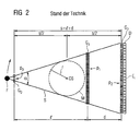
- FIG. 2 shows the basic structure of a grating interferometer in a previously used arrangement with its typical dimensions.
- a focus F is shown a radiation source links, which a with respect to the grating period p 0 relatively coarsely precipitating first absorption grating as follows source grating G 0th
- the measuring field M is arranged, which corresponds approximately to the gantry opening C3 with the radius r.
- the measuring field M is arranged concentrically to the system axis C6 of the gantry.
- the phase grating G 1 follows with a smaller period p 1 and thereupon the third grating structure G 2 with an even smaller grating period p 2 .
- the grating structure G 2 is formed by the analysis grating itself and a subsequent detector D with its detector elements E i .
- this arrangement requires on the detector side a surface area very large and at the same time, however, very finely structured absorption grating as a third lattice structure.
- Such an embodiment is, however, only very expensive to realize ⁇ with a large expansion.
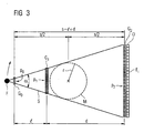
- FIG. 3 Such an exemplary structure of a grating interferometer according to the invention is in the FIG. 3 shown.
- the characteristic distances s, 1 and d are - as well as in the FIG. 2 - also marked.
- a grating interferometer to be used in a CT system can be dimensioned on the one hand, a sufficiently large measuring field with a radius r of 700 mm remains between the second and third lattice structure and, on the other hand, be achieved in the region of the third lattice structure for lattice periods of greater than 10 ⁇ m, which can be produced with a still reasonable outlay.
- FIG. 4 For a better understanding of the measuring principle of the CT systems according to the invention with grating interferometers, is still on the FIG. 4 directed.
- a large-area focus F as an X-ray source and a subsequently arranged source grid G 0 , which here forms the first lattice structure represented.
- quasi-coherent X-rays are emitted in strips at the gaps of the source grating G 0 , while they are largely suppressed in the region of the absorption of the webs of the grating.
- two adjacent coherent X-rays S 1 and S 2 are shown which impinge on a phase grating G 1 in which a diffraction of the beams takes place, so that an interference pattern of the diffracted X-radiation arises following the phase grating G 1 .
- a third grid the analysis grid, which is disposed upstream of a detector D with a plurality of detector elements E i .
- this course of the intensity curve is determined in terms of value as a function of the displacement of a grating and measurement of the radiation intensity as a function of the grating positions. From the knowledge of this course, the phases x 0 can then be evaluated for the phase-contrast imaging, or the average values I med and the deflection amplitude I amp can be evaluated in a known manner for dark-field imaging.
Landscapes
- Health & Medical Sciences (AREA)
- Life Sciences & Earth Sciences (AREA)
- Engineering & Computer Science (AREA)
- Medical Informatics (AREA)
- Pathology (AREA)
- General Health & Medical Sciences (AREA)
- Physics & Mathematics (AREA)
- Nuclear Medicine, Radiotherapy & Molecular Imaging (AREA)
- Radiology & Medical Imaging (AREA)
- Surgery (AREA)
- Veterinary Medicine (AREA)
- Biomedical Technology (AREA)
- Heart & Thoracic Surgery (AREA)
- Molecular Biology (AREA)
- High Energy & Nuclear Physics (AREA)
- Animal Behavior & Ethology (AREA)
- Biophysics (AREA)
- Public Health (AREA)
- Optics & Photonics (AREA)
- Pulmonology (AREA)
- Theoretical Computer Science (AREA)
- Toxicology (AREA)
- Chemical & Material Sciences (AREA)
- Analytical Chemistry (AREA)
- Biochemistry (AREA)
- General Physics & Mathematics (AREA)
- Immunology (AREA)
- Apparatus For Radiation Diagnosis (AREA)
- Analysing Materials By The Use Of Radiation (AREA)
Description
Die Erfindung betrifft ein Röntgen-CT-System zur Röntgen-Phasenkontrast- und/oder Röntgen-Dunkelfeld-Bildgebung eines abgetasteten Untersuchungsobjektes mit mindestens einem, auf einer Gantry angeordneten Gitter-Interferometer, der mindestens eine Gitter-Interferometer aufweisend:
- eine erste Gitterstruktur, welche eine Vielzahl von streifenförmig und parallel angeordneten Röntgenemissionsmaxima und -minima aufweist, die eine erste Gitterperiode besitzen,
- eine zweite Gitterstruktur, die als Phasengitter einen teilweisen Phasenversatz einer durchtretenden Röntgenstrahlung bewirkt und eine zweite Gitterperiode aufweist,
- eine dritte Gitterstruktur mit einer dritten Gitterperiode, mit deren Hilfe eine relative Phasenverschiebungen benachbarter Röntgenstrahlen und/oder deren Streuanteile detektiert werden,
- wobei die drei Gitterstrukturen bezüglich ihrer Abstände untereinander und mindestens die erste und zweite Gitterstruktur bezüglich ihrer Gitterperioden die Talbot-Bedingungen erfüllen, und
- eine Vorrichtung zur wertemäßigen Bestimmung der Phase zwischen benachbarten Röntgenstrahlen und/oder zur wertemäßigen Bestimmung des räumlichen Intensitätsverlaufes je Detektorelement senkrecht zu den Streifen der Gitterstrukturen.
- a first lattice structure having a plurality of stripe-shaped and parallel X-ray emission maxima and minima having a first lattice period,
- a second lattice structure, which as a phase grating causes a partial phase shift of a transmitted X-ray radiation and has a second grating period,
- a third grating structure having a third grating period, with the help of which a relative phase shifts of adjacent X-rays and / or their scattering components are detected,
- wherein the three lattice structures with respect to their distances from each other and at least the first and second lattice structure with respect to their grating periods meet the Talbot conditions, and
- a device for the value determination of the phase between adjacent X-rays and / or for the value determination of the spatial intensity profile per detector element perpendicular to the strips of the lattice structures.
Derartige Röntgen-CT-System zur Röntgen-Phasenkontrast- und/oder Röntgen-Dunkelfeld-Bildgebung eines abgetasteten Untersuchungsobjektes sind allgemein bekannt. Beispielhaft wird auf die Druckschriften
Der Einsatz von röntgenoptischen Gittern erlaubt einerseits die Aufnahme von Röntgenbildern im Phasenkontrast, welche zusätzliche Informationen über ein Untersuchungsobjekt liefern und/oder weniger Strahlendosis bei gleichem Bildkontrast ermöglichen. Andererseits besteht auch die Möglichkeit, dass zur Bildgebung nicht nur die Phaseninformation sondern auch die Amplitudeninformation gestreuter Strahlung verwendet wird. Hierdurch kann eine Bildgebung erzeugt werden, die ausschließlich auf den Streuanteilen der durch das Untersuchungsobjekt gebeugten Röntgenstrahlung basiert, also einer Kleinstwinkelstreuung. Hierdurch können sehr geringe Dichteunterschiede im Untersuchungsobjekt sehr hochauflösend dargestellt werden. Es wird diesbezüglich auf die Veröffentlichung von
Um diese gewünschten Informationen eines mit inkohärenter Strahlung aus Röntgenröhren durchstrahlten Untersuchungsobjektes unter praktischen Bedingungen zu erhalten, müssen drei Gitterstrukturen verwendet werden, deren Perioden etwa im Bereich von 1 bis 100 Mikrometer liegen. Die Stege der mittleren Gitterstruktur - des Analysegitters - bestehen dabei aus phasenschiebendem Material und erzeugen einen Phasenschub von π oder π/2 gemäß
Bisher wurde für Untersuchungen, bei denen tatsächlich an Detektoren pixelweise die Phasendifferenzen zwischen benachbarten Strahlen analytisch detektiert und bestimmt wurden bzw. bei denen zur Bildgebung nicht nur die Phaseninformation sondern auch die Amplitudeninformation analytisch bestimmt wurden, meist eine Anordnung gewählt, bei der der Abstand 1 zwischen erster und zweiter Gitterstruktur G0 und G1 grösser ist als der Abstand d zwischen der zweiten und dritten Gitterstruktur G1 und G2. Die Probe oder die Gantryöffnung war dabei zwischen der ersten und der zweiten Gitterstruktur G0 und G1 angeordnet. Dies hatte insbesondere zur Folge, dass für die entsprechenden Gitterperioden galt: p0 > p1 > p2 . Besonders die technische Realisierung der Gitterstruktur G2 mit Absorberstrukturen erweist sich dabei problematisch, da es die kleinste Gitterperiode p2 hat und die Gitterlinien eine hohe Absorption aufweisen müssen. Dies erfordert den Einsatz hochabsorbierender Materialien wie Gold. Gleichzeitig ist die Fläche von G2 die grösste aller drei Gitter, was neben dem Herstellungsaufwand auch eine erhebliche Menge von teurem Gold erfordert.Up to now, for investigations in which the phase differences between adjacent beams were actually detected analytically at detectors pixel by pixel and in which not only the phase information but also the amplitude information were analytically determined for imaging, an arrangement was chosen in which the
In der Patentschrift
In der Patentschrift
Weiterhin wird in der Patentanmeldung
Es ist Aufgabe der Erfindung ein Röntgen-CT-System zur Röntgen-Phasenkontrast- und/oder Röntgen-Dunkelfeld-Bildgebung eines abgetasteten Untersuchungsobjektes mit mindestens einem auf einer Gantry angeordneten Gitter-Interferometer zu finden, welches im Rahmen der Talbot-Bedingungen für die verwendeten Gitterstrukturen geringere technische Anforderungen setzt und welches für den praktischen Betrieb zur Untersuchung von Objekten in der Größe menschlicher Patienten geeignet ist.The object of the invention is to find an X-ray CT system for X-ray phase contrast and / or X-ray dark field imaging of a scanned examination object with at least one grating interferometer arranged on a gantry, which is used for the Talbot conditions Grid structures sets lower technical requirements and which is suitable for practical operation for the investigation of objects in the size of human patients.
Diese Aufgabe wird durch die Merkmale des unabhängigen Patentanspruches 1 gelöst. Vorteilhafte Weiterbildungen der Erfindung sind Gegenstand untergeordneter Ansprüche.This object is solved by the features of
Die Erfinder haben folgendes erkannt:
Die Bedingungen (=Talbot-Bedingungen) der Gitterperioden p0, p1, und p2 der Gitterstrukturen G0, G1 und G2 und die Abstände 1 zwischen G0 und G1 und d zwischen G1 und G2 können wie folgt beschrieben werden: 
The conditions (= Talbot conditions) of the grating periods p 0 , p 1 and p 2 of the grating structures G 0 , G 1 and G 2 and the
Das Gitter G1, welches von einer sphärischen Welle mit dem Radius 1 und der Wellenlänge λ beleuchtet wird, erzeugt durch den Talbot-Effekt im Abstand TD' ein Interferenzmuster mit maximalem Kontrast. Es gilt: 

Für eine gegebene Gesamtlänge des Messaufbaues s=1+d ergibt sich mit Hilfe der Gleichungen [2] und [3] eine erstaunlich einfache quadratische Gleichung für 1 mit: ![]()

![]()
Für ![]()
![]()

![]()
![]()
Für ![]()
![]()
Entsprechend der Erkenntnis der Erfinder ist es entgegen der bisherigen Praxis jedoch besonders günstig einen Aufbau zu wählen, bei dem 1 kleiner als d ist. Hierdurch kann nämlich aufgrund der oben beschriebenen Talbot-Bedingungen erreicht werden, dass die Gitterperiode p2 der dritten Gitterstruktur G2 größer als die Gitterperiode p1 der zweiten Gitterstruktur G1 und diese wiederum größer als die Gitterperiode p2 der zweiten Gitterstruktur G2 ausfällt. Da geometrisch bedingt die erste Gitterstruktur G0 in ihrer Fläche kleiner ausfällt als die der zweiten und die kleiner als die der dritten Gitterstruktur, ergibt sich ein wesentlich einfacherer Aufbau des Interferometers.According to the knowledge of the inventors, however, it is particularly favorable to choose a construction in which 1 is smaller than d, contrary to the previous practice. Because of this, it can be achieved on account of the above-described Talbot conditions that the grating period p 2 of the third grating structure G 2 is greater than the grating period p 1 of the second grating structure G 1 and this in turn larger than the grating period p 2 of the second grating structure G 2 . Since, geometrically, the first grating structure G 0 has a smaller surface area than the second grating structure and less than the third grating structure, this results in a considerably simpler structure of the interferometer.
Eine solche Anordnung bringt im Vergleich zu der bisher verwendeten Anordnung folgende Vorteile mit sich:
- 1. Das Gitter mit der kleinsten Gitterperiode, welches entsprechend schwierig in der Herstellung ist, ist nun das G0, welches eine viel kleinere Fläche hat als G2. Dies reduziert Aufwand und Kosten.
- 2. G0 kann durch eine entsprechend strukturierte Anode bzw. einen entsprechend strukturierten Elektronenstrahl auf einer Anode ersetzt werden, was möglicherweise einfacher zu realisieren ist als ein Gitter und sich leichter schrittweise oder kontinuierlich bewegen lässt.
- 3. Das Gitter G1 hat zwar die gleiche Periode p1, jedoch verkleinert sich seine Abmessung deutlich in Vergleich zur herkömmlichen Anordnung (dadurch ebenfalls Kostenreduzierung).
- 4. Das Gitter mit der grössten Fläche ist nun (nur) das Gitter G2, die Anforderungen an die Mikrostrukturierung ist wesentlich geringer wegen der grossen Gitterperiode P2.
- 5. Das Gitter G2 kann wegen der gröberen Periode auch aus weniger stark absorbierendem Material als dem bisher verwendeten Gold gefertigt werden, da die Stege vergleichsweise problemlos dicker gemacht werden können. Die Verwendung z.B. von Blei statt Gold kann die Kosten deutlich senken.
- 6. p2 kann so gross gewählt werden, dass es weggelassen und durch einen Streifen- oder Pixeldetektor mit entsprechender Periode ersetzt werden kann. Das vereinfacht den Aufbau und vermeidet, dass die Hälfte der hinter der Probe verfügbaren Röntgenphotonen in G2 absorbiert wird.
- 1. The grating with the smallest grating period, which is correspondingly difficult to produce, is now the G 0 , which has a much smaller area than G 2 . This reduces effort and costs.
- 2. G 0 can be replaced by a correspondingly structured anode or a correspondingly structured electron beam on an anode, which may be easier to implement than a grid and is easier to move stepwise or continuously.
- 3. Although the grating G 1 has the same period p 1 , its dimension decreases significantly in comparison to the conventional arrangement (thereby also cost reduction).
- 4. The grid with the largest area is now (only) the grid G 2 , the requirements for the microstructuring is much lower because of the large grating period P 2 .
- 5. The grating G 2 can be made of less strongly absorbing material than the previously used gold because of the coarser period, since the webs can be made comparatively easily thicker. Using eg lead instead of gold can significantly reduce costs.
- 6. p 2 can be chosen so large that it can be omitted and replaced by a strip or pixel detector with corresponding period. This simplifies the design and avoids that half of the available behind the sample X-ray photons in G 2 is absorbed.
Die Phasensensitivität der herkömmlichen und der hier vorgeschlagenen Anordnung ist nach momentanen Erkenntnissen gleich.The phase sensitivity of the conventional and the arrangement proposed here is the same according to current findings.
Entsprechend dieser Erkenntnis schlagen die Erfinder vor, ein an sich bekanntes Röntgen-CT-System zur Röntgen-Phasenkontrast- und/oder Röntgen-Dunkelfeld-Bildgebung eines abgetasteten trast- und/oder Röntgen-Dunkelfeld-Bildgebung eines abgetasteten Untersuchungsobjektes mit mindestens einem, auf einer Gantry angeordneten Gitter-Interferometer, zu verbessern, wobei das mindestens eine Gitter-Interferometer aufweist:
- eine erste Gitterstruktur, welche eine Vielzahl von streifenförmig und parallel angeordneten Röntgenemissionsmaxima und -minima aufweist, die eine erste Gitterperiode besitzen,
- eine zweite streifenförmige Gitterstruktur, die als Phasengitter einen teilweisen Phasenversatz einer durchtretenden Röntgenstrahlung bewirkt und eine zweite Gitterperiode aufweist,
- eine dritte streifenförmige Gitterstruktur mit einer dritten Gitterperiode, mit deren Hilfe eine relative Phasenverschiebungen benachbarter Röntgenstrahlen und/oder deren Streuanteile detektiert werden,
- wobei die drei Gitterstrukturen bezüglich ihrer Abstände untereinander und mindestens die erste und zweite Gitterstruktur bezüglich ihrer Gitterperioden die Talbot-Bedingungen erfüllen, und
- eine Vorrichtung zur wertemäßigen Bestimmung der Phase zwischen benachbarten Röntgenstrahlen und/oder zur wertemäßigen Bestimmung des räumlichen Intensitätsverlaufes je Detektorelement senkrecht zu den Streifen der Gitterstrukturen.
- a first lattice structure having a plurality of stripe-shaped and parallel X-ray emission maxima and minima having a first lattice period,
- a second strip-like lattice structure which, as a phase grating, effects a partial phase offset of a passing x-ray radiation and has a second grating period,
- a third strip-like grating structure having a third grating period, with the aid of which a relative phase shifts of adjacent X-rays and / or their scattering components are detected,
- wherein the three lattice structures with respect to their distances from each other and at least the first and second lattice structure with respect to their grating periods meet the Talbot conditions, and
- a device for the value determination of the phase between adjacent X-rays and / or for the value determination of the spatial intensity profile per detector element perpendicular to the strips of the lattice structures.
Die erfindungsgemäße Verbesserung besteht darin, dass die dritte Gitterstruktur eine Gitterperiode aufweist, die um einen Faktor 2 bis 5 größer ist als die Gitterperiode der ersten Gitterstruktur.The improvement according to the invention consists in that the third lattice structure has a lattice period that is larger by a factor of 2 to 5 than the lattice period of the first lattice structure.
Weiterhin ist es zur Untersuchung großer Objekte günstig, wenn das mindestens eine Gitter-Interferometer einen Strahlengang aufweist, der in Richtung eines Rotationswinkels der Gantry eine Aufweitung von mindestens 30°, vorzugsweise von mindestens 35° bis 40°, aufweist.Furthermore, it is favorable for the examination of large objects if the at least one grating interferometer has a beam path which has a widening of at least 30 °, preferably of at least 35 ° to 40 °, in the direction of a rotation angle of the gantry.
Vorteilhaft kann das Untersuchungsobjekt zwischen der zweiten Gitterstruktur und der dritten Gitterstruktur positioniert werden, hierdurch kann sich ein relativ großes und zentrales Messfeld ergeben.Advantageously, the examination object can be positioned between the second lattice structure and the third lattice structure, as a result of which a relatively large and central measurement field can result.
Vorteilhaft kann bei dem erfindungsgemäßen Röntgen-CT-System auch eine Ausdehnung der ersten Gitterstruktur in Umfangsrichtung der Gantry gewählt werden, die 1 bis 3 cm, vorzugsweise etwa 2 cm, beträgt.Advantageously, in the X-ray CT system according to the invention, an extension of the first lattice structure in the circumferential direction of the gantry, which is 1 to 3 cm, preferably about 2 cm, is selected.
Weiterhin kann die Ausdehnung der dritten Gitterstruktur in Richtung der größten Auffächerung der verwendeten Strahlung mindestens um den Faktor zwei größer sein als die Ausdehnung der zweiten Gitterstruktur in Richtung der größten Auffächerung der verwendeten Strahlung.Furthermore, the extent of the third lattice structure in the direction of the largest fanning out of the radiation used can be at least a factor of two greater than the extent of the second lattice structure in the direction of the greatest fanning out of the radiation used.
Bezüglich des Verhältnisses 1/d des Abstandes 1 zwischen der ersten und zweiten Gitterstruktur und dem Abstand d zwischen der zweiten und dritten Gitterstruktur wird vorgeschlagen, dass dieser kleiner 1 ist, vorzugsweise zwischen der Werten 1/d= 0,4 bis 0,2 liegt. Damit ist der Aufbau eines Gitter-Interferometers für ein CT-System möglich, der ein ausreichend großes Messfeld ermöglicht, welches sich im Drehzentrum einer Gantry befindet, wenn das Interferometer eingebaut ist.With respect to the
Die erste Gitterstruktur kann in einer konventionellen Ausführung ein Quellengitter mit in Strahlrichtung vorgelagerten Fokus einer Röntgenquelle aufweisen. Damit kann auf bekannte Konstruktionen von Röntgenröhren zurückgegriffen werden, wobei lediglich im Bereich des Austrittsfensters der Röhre ein relativ kleines Absorptionsgitter als Quellengitter zu positionieren ist.In a conventional embodiment, the first grating structure may comprise a source grating with a focus of an X-ray source upstream in the beam direction. This makes it possible to resort to known constructions of x-ray tubes, wherein only in the region of the exit window of the tube a relatively small absorption grating is to be positioned as source grating.
Alternativ zur Verwendung eines Quellengitters kann die erste Gitterstruktur auch durch auf einer Anode streifenförmig abwechselnd austretende Strahlungsmaxima und Strahlungsminima gebildet werden.As an alternative to the use of a source grating, the first grating structure can also be formed by radiation maxima and radiation minima alternately emerging in strip form on an anode.
Zur Ausbildung solcher streifenförmiger Strahlungsmaxima und Strahlungsminima von Röntgenstrahlung sind unterschiedliche Methoden bekannt. Beispielsweise kann eine Anode verwendet werden, die eine inhomogen strukturierte Anodenoberfläche besitzt, wodurch die streifenförmig abwechselnd austretenden Strahlungsmaxima und Strahlungsminima entstehen. Eine solche Inhomogenität kann dadurch gebildet werden, dass die Anodenoberfläche streifenförmig angeordnete Erhebungen und/oder Vertiefungen aufweist. Es besteht jedoch auch die Möglichkeit auf der Anodenoberfläche streifenförmig Materialien mit unterschiedlicher Kernladungszahl anzuordnen. Auch eine Kombination der beiden letztgenannten Möglichkeiten ist möglich, indem in den Vertiefungen andere Materialien auf der Oberfläche vorliegen als auf relativen Erhebungen hierzu. Eine entsprechende Ausbildung ist in der Druckschrift
Eine weitere Möglichkeit streifenförmige Strahlungsmaxima und -minima auf einer Oberfläche zu erzeugen, besteht darin, eine auf elektro-magnetischer Basis arbeitende Ablenkungsvorrichtung eines Elektronenstrahls vorzusehen, die mit dem Elektronenstrahl die Anodenoberfläche streifenförmig abtastet und damit die streifenförmig abwechselnd austretenden Strahlungsmaxima und Strahlungsminima erzeugt. Auch diese Variante der Ausbildung ist in der Druckschrift
Zur wertemäßigen Analyse einer Phase zwischen benachbarten Röntgenstrahlen kann die dritte Gitterstruktur derart aufgebaut sein, dass sie mindestens ein Analysegitter mit danach angeordnetem ortsauflösenden Detektor mit einer Vielzahl von Detektorelementen aufweist. Hierbei kann weiterhin eine Vorrichtung zum kontrollierten Ortsversatz senkrecht zu ihren Gitterlinien und mit einer Ortsauflösung im Bereich der Periode der ersten Gitterstruktur vorgesehen werden. Alternativ zur Bewegung des Analysegitters kann auch die zweite Gitterstruktur eine Vorrichtung zum kontrollierten Ortsversatz senkrecht zu ihren Gitterlinien und mit einer Ortsauflösung im Bereich der Periode der ersten Gitterstruktur oder auch die dritte Gitterstruktur eine Vorrichtung zum kontrollierten Ortsversatz senkrecht zu ihren Gitterlinien und mit einer Ortsauflösung im Bereich der Periode der dritten Gitterstruktur aufweisen. Grundsätzlich besteht auch die Möglichkeit das Objekt selbst zu bewegen, allerdings erscheint dies zumindest bei einem Scan eines Patienten nicht praktikabel.For the value analysis of a phase between adjacent X-rays, the third grating structure may be constructed such that it has at least one analysis grating with a spatially resolving detector having a plurality of detector elements arranged thereafter. In this case, furthermore, a device for controlled spatial displacement perpendicular to its grating lines and with a spatial resolution in the region of the period of the first grating structure can be provided. As an alternative to the movement of the analysis grating, the second grating structure can also have a device for controlled spatial displacement perpendicular to its grating lines and with a spatial resolution in the region of the period of the first grating structure or else the third grating structure has a device for controlled spatial displacement perpendicular to its grating lines and with a spatial resolution in the region of the period of the third grating structure. In principle, it is also possible to move the object itself, but this does not seem practical at least for a patient scan.
Anstelle der Bewegung von Gitterstrukturen kann auch eine dritte Gitterstruktur verwendet werden, die durch eine Vielzahl von pro detektiertem Röntgenstrahl streifenförmig ortsaufgelösten Detektorelementen gebildet wird, wie es beispielsweise in der Druckschrift
Im Folgenden wird die Erfindung mit Hilfe der Figuren näher beschrieben, wobei nur die zum Verständnis der Erfindung notwendigen Merkmale dargestellt sind. Es werden folgende Bezugszeichen, Variablen und Kurzbezeichnungen verwendet: C1: Röntgen-CT-System; C2: Gantrygehäuse; C3: Gantryöffnung; C4: verschiebbare Patientenliege; C5: Patient; C6: Systemachse; C7: Steuer- und Recheneinheit; C8: Speicher; d: Abstand zwischen zweiten Gitter und dritten Gitter; D: Detektor; Ei: Detektorelemente; F: Fokus; G0: Quellengitter; G1: Phasengitter; G2: Analysegitter; 1: Abstand zwischen erstem Gitter und zweitem Gitter; M: Messfeld; p0: Gitterperiode der ersten Gitterstruktur; p1: Gitterperiode der zweiten Gitterstruktur; p2: Gitterperiode der dritten Gitterstruktur; Prg1-Prgn: Computer-Programme; r: Radius; s: Abstand zwischen erstem Gitter und dritten Gitter; S: Strahlkegel; S1, S2: benachbarte Röntgenstrahlen; α: Aufweitung.In the following the invention will be described in more detail with the aid of the figures, wherein only the features necessary for understanding the invention are shown. The following reference numerals, variables and abbreviations are used: C1: X-ray CT system; C2: gantry housing; C3: gantry opening; C4: sliding patient bed; C5: patient; C6: system axis; C7: control and computing unit; C8: memory; d: distance between second grid and third grid; D: detector; E i : detector elements; F: focus; G 0 : source grid; G 1 : phase grating; G 2 : analysis grid; 1: distance between first grid and second grid; M: measuring field; p 0 : grating period of the first grating structure; p 1 : grating period of the second grating structure; p 2 : grating period of the third lattice structure; Prg 1 prg n : computer programs; r: radius; s: distance between first grid and third grid; S: beam cone; S 1 , S 2 : adjacent X-rays; α: expansion.
Es zeigen im Einzelnen:
- FIG 1
- ein Röntgen-CT-System mit erfindungsgemäßem Strahler-Detektor-System in 3D-Darstellung,
- FIG 2
- ein bekanntes, als Gitter-Interferometer aufgebautes, Strahler-Detektor-System eines CTs,
- FIG 3
- ein erfindungsgemäßes Strahler-Detektor-System und
- FIG 4
- eine Prinzipdarstellung des Messprinzips zur Röntgen-Phasenkontrast- und Röntgen-Dunkelfeld-Messung.
- FIG. 1
- an X-ray CT system with inventive emitter-detector system in 3D representation,
- FIG. 2
- a known, designed as a grid interferometer, emitter-detector system of a CT,
- FIG. 3
- an inventive emitter-detector system and
- FIG. 4
- a schematic representation of the measuring principle for X-ray phase contrast and X-ray darkfield measurement.
In der
Zur Messung wird der Patient C5 mit Hilfe der verschiebbaren Patientenliege C4 bei rotierender Gantry entlang der Systemachse C6 sequentiell oder kontinuierlich durch das Messfeld geschoben, wobei eine Abtastung durch den einen oder mehrere mit der Gantry um die Systemachse C6 rotierende Gitter-Interferometer durchgeführt wird. Bei der Abtastung und der nachfolgenden Auswertung der Detektordaten werden quantitativ die Phasenunterschiede benachbarter kohärenter Röntgenstrahlen bestimmt und/oder es werden Dunkelfeld-CT-Aufnahmen aus Projektionen ähnlich den bekannten Dunkelfeldaufnahmen aus der Mikroskopie rekonstruiert. Hierzu werden zunächst aus einer Vielzahl von Projektionswinkeln die gebeugten Strahlungsanteile der abtastenden Röntgenstrahlung bestimmt. Anschließend werden diese projektiven Aufnahmen verwendet, um mit Hilfe an sich bekannter Rekonstruktionstechniken tomographische Bilddaten zu rekonstruieren, die volumenspezifische Kleinstwinkelstreuungen wiedergeben, wie es beispielsweise in
Zur Durchführung der Steuerung, Messung und der Rekonstruktionen können hierbei die Computerprogramme Prg1-Prgn dienen, die in einem Speicher C8 der Steuer- und Recheneinheit C7 abgelegt sind und die bei Bedarf abgerufen und ausgeführt werden können.To carry out the control, measurement and reconstructions, the computer programs Prg 1 -Prg n can be used here, which are stored in a memory C8 of the control and arithmetic unit C7 and can be called up and executed as required.
Die
Wie aus dem gezeigten Beispiel zu erkennen ist, erfordert diese Anordnung auf der Detektorseite ein flächenmäßig sehr großes und gleichzeitig jedoch sehr feinstrukturiertes Absorptionsgitter als dritte Gitterstruktur. Eine solche Ausführung ist bei einer großen Aufweitung α jedoch nur sehr aufwendig zu realisieren.As can be seen from the example shown, this arrangement requires on the detector side a surface area very large and at the same time, however, very finely structured absorption grating as a third lattice structure. Such an embodiment is, however, only very expensive to realize α with a large expansion.
Es wird daher erfindungsgemäß eine Ausführung vorgeschlagen, bei der die zweite Gitterstruktur G1 auf die andere Seite des Messfeldes M verlegt wird und die Gitterperioden p0,p1 und p2 in Strahlrichtung größer werden, so dass die flächenmäßig größte dritte Gitterstruktur G2 auch am einfachsten herzustellen ist.It is therefore proposed according to the invention an embodiment in which the second grating structure G 1 is moved to the other side of the measuring field M and the grating periods p 0 , p 1 and p 2 are larger in the beam direction, so that the largest in area third grating structure G 2 also is the easiest to produce.
Solch ein beispielhafter Aufbau eines erfindungsgemäßen Gitter-Interferometers ist in der
Wie aus der Tabelle 1 hervorgeht, kann ein in einem CT-System einzusetzendes Gitter-Interferometer so dimensioniert werden, dass einerseits ein ausreichend großes Messfeld mit einem Radius r von 700 mm zwischen der zweiten und dritten Gitterstruktur verbleibt und andererseits im Bereich der dritten Gitterstruktur für Gitterperioden von größer 10µm erreicht werden, die mit einem noch vertretbaren Aufwand erstellbar sind.As can be seen from Table 1, a grating interferometer to be used in a CT system can be dimensioned on the one hand, a sufficiently large measuring field with a radius r of 700 mm remains between the second and third lattice structure and, on the other hand, be achieved in the region of the third lattice structure for lattice periods of greater than 10 μm, which can be produced with a still reasonable outlay.
Zum besseren Verständnis des Messprinzips der erfindungsgemäßen CT-Systeme mit Gitter-Interferometern, wird noch auf die
Betracht man den Effekt der Verschiebung einer Gitterstruktur in x-Richtung auf die Intensitätsmessung eines Detektorelementes Ei, so ergibt sich ein Intensitätsverlauf I(x) in Abhängigkeit von der Gitterauslenkung x, wie er unten in der ![]()
![]()
Der Verlauf dieser Kurve lässt sich durch die Angabe des Mittelwertes Imed, die Angabe der Auslenkungsamplitude Iamp und der Phase x0, mit der die sinusförmige Auslenkung verläuft, vollständig beschreiben.The course of this curve can be completely described by the indication of the mean value I med , the indication of the deflection amplitude I amp and the phase x 0 , with which the sinusoidal deflection runs.
Im erfindungsgemäßen CT-System wird dieser Verlauf der Intensitätskurve in Abhängigkeit von der Verschiebung eines Gitters und Messung der Strahlungsintensität in Abhängigkeit von den Gitterpositionen wertemäßig ermittelt. Aus der Kenntnis dieses Verlaufes können dann für die Phasenkontrast-Bildgebung die Phasen x0 ausgewertet werden oder für eine Dunkelfeld-Bildgebung die Mittelwerte Imed und die Auslenkungsamplitude Iamp in bekannter Weise ausgewertet werden.In the CT system according to the invention, this course of the intensity curve is determined in terms of value as a function of the displacement of a grating and measurement of the radiation intensity as a function of the grating positions. From the knowledge of this course, the phases x 0 can then be evaluated for the phase-contrast imaging, or the average values I med and the deflection amplitude I amp can be evaluated in a known manner for dark-field imaging.
Claims (19)
- X-ray CT system (C1) for X-ray phase contrast and/or X-ray dark field imaging of a scanned examination subject (C5) comprising at least one grating interferometer arranged on a gantry, said at least one grating interferometer comprising:1.1. a first grating structure (G0) having a plurality of band-shaped X-ray emission maxima and minima arranged in parallel, said maxima and minima exhibiting a first grating period (p0),1.2. a second band-shaped grating structure (G1) that produces, as a phase grating, a partial phase offset of X-ray radiation passing therethrough and that exhibits a second grating period (p1),1.3. a third band-shaped grating structure (G2) with a third grating period (p2), with which relative phase shifts of adjacent X-rays (S1, S2) and/or the scatter components thereof are detected,1.4. wherein the three grating structures (G0, G1, G2) with regard to the distances (1, d) from one another, and at least the first and second grating structures (G0, G1) with regard to their grating periods (p0, p1) satisfy the Talbot conditions, and1.5. a device configured for value-based determination of the phase between adjacent X-rays and/or for value-based determination of the spatial intensity curve per detector element perpendicular to the bands of the grating structures,
characterised in that1.6. the third grating structure (G2) has a grating period (p2) that is larger by a factor of 2 to 5 than the grating period (p0) of the first grating structure (G0). - X-ray CT system (C1) according to preceding claim 1, characterised in that the at least one grating interferometer has a beam path that, in the direction of a rotation angle of the gantry, exhibits a divergence (α) of at least 30°.
- X-ray CT system (C1) according to preceding claim 1 or 2, characterised in that the at least one grating interferometer has a beam path that, in the direction of a rotation angle of the gantry, exhibits a divergence (α) of at least 35° to 40°.
- X-ray CT system (C1) according to one of the preceding claims 1 to 3, characterised in that the examination subject is placed between the second grating structure (G1) and the third grating structure (G2).
- X-ray CT system (C1) according to one of the preceding claims 1 to 4, characterised in that the dimension of the first grating structure (G0) in a circumferential direction of the gantry is 1 to 3 cm.
- X-ray CT system (C1) according to one of the preceding claims 1 to 5, characterised in that the dimension of the third grating structure (G2) in a direction of greatest divergence of the radiation used is greater by at least a factor of two than the dimension of the second grating structure (G1) in the direction of greatest divergence of the radiation used.
- X-ray CT system (C1) according to one of the preceding claims 1 to 6, characterised in that the ratio (l/d) of the distance (1) between the first and second grating structures (G0, G1) and the distance between the second and third grating structures (G1, G2) is smaller than 1.
- X-ray CT system (C1) according to one of the preceding claims 1 to 6, characterised in that the ratio (l/d) of the distance (1) between the first and second grating structures (G0, G1) and the distance between the second and third grating structures (G1, G2) is between the values l/d= 0.5 to 0.1.
- X-ray CT system (C1) according to one of the preceding claims 1 to 8, characterised in that the first grating structure (G0) has a source grating (G0) with the focus (F) of an X-ray source situated upstream therefrom in the beam direction.
- X-ray CT system (C1) according to one of the preceding claims 1 to 8, characterised in that the first grating structure (G0) is formed by radiation maxima and radiation minima alternatingly emitted in bands at an anode.
- X-ray CT system (C1) according to preceding claim 10, characterised in that the anode has an inhomogeneously structured anode surface, at which the alternatingly emitted band-shaped radiation maxima and radiation minima bands are created.
- X-ray CT system (C1) according to preceding claim 11, characterised in that the anode surface comprises elevations and/or depressions arranged in bands.
- X-ray CT system (C1) according to preceding claim 11, characterised in that the anode surface is comprised of materials with different atomic number arranged in bands.
- X-ray CT system (C1) according to preceding claim 10, characterised in that a deflection device for an electron beam is provided that operates on an electro-magnetic basis, which deflection device scans the surface of the anode in a band-shaped manner with the electron beam and generates the alternatingly emitted radiation maxima and radiation minima in bands.
- X-ray CT system (C1) according to one of the preceding claims 1 to 14, characterised in that the third grating structure (G2) has at least one analysis grating with a subsequently arranged, spatially resolving detector (D) comprising a plurality of detector elements (Ei).
- X-ray CT system (C1) according to one of the preceding claims 1 to 15, characterised in that the first grating structure (G0) has a device for monitored spatial offset perpendicular to the grating lines thereof and with a spatial resolution approximating the period (p0) of the first grating structure (G0).
- X-ray CT system (C1) according to one of the preceding claims 1 to 15, characterised in that the second grating structure (G1) has a device for monitored spatial offset perpendicular to the grating lines thereof and with a spatial resolution approximating the period (p1) of the second grating structure (G1).
- X-ray CT system (C1) according to one of the preceding claims 1 to 15, characterised in that the third grating structure (G2) has a device for monitored spatial offset perpendicular to the grating lines thereof and with a spatial resolution approximating the period (p2) of the third grating structure (G2).
- X-ray CT system (C1) according to one of the preceding claims 1 to 14, characterised in that the third grating structure (G2) is formed by a plurality of band-shaped, spatially resolved detector elements (Ei) per detected X-ray beam.
Priority Applications (3)
| Application Number | Priority Date | Filing Date | Title |
|---|---|---|---|
| EP08017240A EP2168488B1 (en) | 2008-09-30 | 2008-09-30 | X-ray CT system for x-ray phase contrast and/or x-ray dark field imaging |
| DE102009043067A DE102009043067A1 (en) | 2008-09-30 | 2009-09-25 | X-ray CT system for X-ray phase contrast and / or X-ray dark field imaging |
| US12/570,178 US7983381B2 (en) | 2008-09-30 | 2009-09-30 | X-ray CT system for x-ray phase contrast and/or x-ray dark field imaging |
Applications Claiming Priority (1)
| Application Number | Priority Date | Filing Date | Title |
|---|---|---|---|
| EP08017240A EP2168488B1 (en) | 2008-09-30 | 2008-09-30 | X-ray CT system for x-ray phase contrast and/or x-ray dark field imaging |
Publications (2)
| Publication Number | Publication Date |
|---|---|
| EP2168488A1 EP2168488A1 (en) | 2010-03-31 |
| EP2168488B1 true EP2168488B1 (en) | 2013-02-13 |
Family
ID=40445441
Family Applications (1)
| Application Number | Title | Priority Date | Filing Date |
|---|---|---|---|
| EP08017240A Active EP2168488B1 (en) | 2008-09-30 | 2008-09-30 | X-ray CT system for x-ray phase contrast and/or x-ray dark field imaging |
Country Status (3)
| Country | Link |
|---|---|
| US (1) | US7983381B2 (en) |
| EP (1) | EP2168488B1 (en) |
| DE (1) | DE102009043067A1 (en) |
Cited By (2)
| Publication number | Priority date | Publication date | Assignee | Title |
|---|---|---|---|---|
| CN107847199A (en) * | 2015-06-30 | 2018-03-27 | 皇家飞利浦有限公司 | Scanning X-ray apparatus with full filed detector |
| CN109580667A (en) * | 2018-12-05 | 2019-04-05 | 中国科学技术大学 | Monochromatic light grid phase contrast imaging method and system |
Families Citing this family (59)
| Publication number | Priority date | Publication date | Assignee | Title |
|---|---|---|---|---|
| JP5339975B2 (en) * | 2008-03-13 | 2013-11-13 | キヤノン株式会社 | Phase grating used for X-ray phase imaging, X-ray phase contrast image imaging apparatus using the phase grating, X-ray computed tomography system |
| DE102009004702B4 (en) * | 2009-01-15 | 2019-01-31 | Paul Scherer Institut | Arrangement and method for projective and / or tomographic phase-contrast imaging with X-radiation |
| KR101180067B1 (en) | 2010-05-25 | 2012-09-05 | 단국대학교 산학협력단 | X-ray In-line Grating Interferometer |
| BR112013009253A2 (en) * | 2010-10-19 | 2019-09-24 | Koninl Philips Electronics Nv | diffraction grating for differential phase contrast imaging, detector arrangement of an x-ray system for generating phase contrast images of an object, x-ray clinic imaging system, method for obtaining contrast imaging phase differential, computer program element and computer readable medium |
| WO2012052881A1 (en) * | 2010-10-19 | 2012-04-26 | Koninklijke Philips Electronics N.V. | Differential phase-contrast imaging |
| JP2012095865A (en) * | 2010-11-02 | 2012-05-24 | Fujifilm Corp | Radiographic apparatus and radiographic system |
| WO2012063169A1 (en) * | 2010-11-08 | 2012-05-18 | Koninklijke Philips Electronics N.V. | Grating for phase contrast imaging |
| JP5150711B2 (en) * | 2010-12-07 | 2013-02-27 | 富士フイルム株式会社 | Radiography apparatus and radiation imaging system |
| RU2620892C2 (en) | 2011-07-04 | 2017-05-30 | Конинклейке Филипс Н.В. | Image forming device of phase contrast |
| US9486175B2 (en) | 2011-07-04 | 2016-11-08 | Koninklijke Philips N.V. | Phase contrast imaging apparatus |
| EP2737302B1 (en) | 2011-07-29 | 2017-03-22 | The Johns Hopkins University | Differential phase contrast x-ray imaging system and components |
| DE102011082878A1 (en) * | 2011-09-16 | 2013-03-21 | Siemens Aktiengesellschaft | X-ray detector of a grid-based phase-contrast X-ray device and method for operating a grid-based phase-contrast X-ray device |
| EP2586373B1 (en) * | 2011-10-28 | 2014-12-03 | CSEM Centre Suisse D'electronique Et De Microtechnique SA | X-ray interferometer |
| US20150117599A1 (en) | 2013-10-31 | 2015-04-30 | Sigray, Inc. | X-ray interferometric imaging system |
| US9597050B2 (en) * | 2012-01-24 | 2017-03-21 | Koninklijke Philips N.V. | Multi-directional phase contrast X-ray imaging |
| WO2014137318A1 (en) * | 2012-03-05 | 2014-09-12 | University Of Rochester | Methods and apparatus for differential phase-contrast cone-beam ct and hybrid cone-beam ct |
| DE102012005767A1 (en) * | 2012-03-25 | 2013-09-26 | DüRR DENTAL AG | Phase contrast X-ray tomography apparatus |
| KR101378757B1 (en) * | 2012-08-30 | 2014-03-27 | 한국원자력연구원 | Radiation imaging equipment and method available to obtain element date of material and select dimensions of image |
| US8989347B2 (en) | 2012-12-19 | 2015-03-24 | General Electric Company | Image reconstruction method for differential phase contrast X-ray imaging |
| US9014333B2 (en) | 2012-12-31 | 2015-04-21 | General Electric Company | Image reconstruction methods for differential phase contrast X-ray imaging |
| JP2014178130A (en) * | 2013-03-13 | 2014-09-25 | Canon Inc | X-ray imaging device and x-ray imaging system |
| DE102013205406A1 (en) * | 2013-03-27 | 2014-10-16 | Siemens Aktiengesellschaft | X-ray imaging system for X-ray imaging at high image frequencies of an examination subject by direct measurement of the interference pattern |
| JP2015072263A (en) * | 2013-09-09 | 2015-04-16 | キヤノン株式会社 | X-ray imaging system |
| US10297359B2 (en) | 2013-09-19 | 2019-05-21 | Sigray, Inc. | X-ray illumination system with multiple target microstructures |
| US10295485B2 (en) | 2013-12-05 | 2019-05-21 | Sigray, Inc. | X-ray transmission spectrometer system |
| US10416099B2 (en) | 2013-09-19 | 2019-09-17 | Sigray, Inc. | Method of performing X-ray spectroscopy and X-ray absorption spectrometer system |
| US10269528B2 (en) | 2013-09-19 | 2019-04-23 | Sigray, Inc. | Diverging X-ray sources using linear accumulation |
| USRE48612E1 (en) | 2013-10-31 | 2021-06-29 | Sigray, Inc. | X-ray interferometric imaging system |
| US10304580B2 (en) | 2013-10-31 | 2019-05-28 | Sigray, Inc. | Talbot X-ray microscope |
| WO2015067461A1 (en) * | 2013-11-05 | 2015-05-14 | Koninklijke Philips N.V. | X-ray imaging device with fast spatial modulation of photon flux |
| CN104622492A (en) * | 2013-11-11 | 2015-05-20 | 中国科学技术大学 | X-ray grating phase-contrast imaging device and method |
| JP2015166676A (en) * | 2014-03-03 | 2015-09-24 | キヤノン株式会社 | X-ray imaging system |
| EP2942619A1 (en) | 2014-05-07 | 2015-11-11 | Paul Scherrer Institut | Tilted-grating approach for scanning-mode X-ray grating interferometry |
| US10401309B2 (en) | 2014-05-15 | 2019-09-03 | Sigray, Inc. | X-ray techniques using structured illumination |
| US10117629B2 (en) | 2014-12-03 | 2018-11-06 | Board Of Supervisors Of Louisiana State University And Agricultural And Mechanical College | High energy grating techniques |
| US10352880B2 (en) | 2015-04-29 | 2019-07-16 | Sigray, Inc. | Method and apparatus for x-ray microscopy |
| US10295486B2 (en) | 2015-08-18 | 2019-05-21 | Sigray, Inc. | Detector for X-rays with high spatial and high spectral resolution |
| US11116465B2 (en) | 2015-09-16 | 2021-09-14 | Koninklijke Philips N.V. | Dark-field enhanced virtual x-ray colonoscopy |
| CN107024490B (en) * | 2016-01-29 | 2019-07-05 | 中国科学院高能物理研究所 | Single exposure grating shearing imaging device and data acquisition and information extracting method |
| CN109690627A (en) | 2016-09-08 | 2019-04-26 | 皇家飞利浦有限公司 | Improved phase contrast and dark field CT algorithm for reconstructing |
| EP3538879B1 (en) * | 2016-11-10 | 2022-06-01 | Koninklijke Philips N.V. | Grating-based phase contrast imaging |
| US10247683B2 (en) | 2016-12-03 | 2019-04-02 | Sigray, Inc. | Material measurement techniques using multiple X-ray micro-beams |
| US11026643B2 (en) | 2016-12-06 | 2021-06-08 | Koninklijke Philips N.V. | Interferometer grating support for grating-based x-ray imaging and/or a support bracket therefor |
| EP3435325A1 (en) | 2017-07-26 | 2019-01-30 | Koninklijke Philips N.V. | Scatter correction for dark field imaging |
| EP3454051A1 (en) | 2017-09-06 | 2019-03-13 | Koninklijke Philips N.V. | Diffraction grating for x-ray phase contrast and/or dark-field imaging |
| EP3494885A1 (en) * | 2017-12-07 | 2019-06-12 | Koninklijke Philips N.V. | Apparatus for presentation of dark field x-ray image information |
| US10578566B2 (en) | 2018-04-03 | 2020-03-03 | Sigray, Inc. | X-ray emission spectrometer system |
| DE112019002822T5 (en) | 2018-06-04 | 2021-02-18 | Sigray, Inc. | WAVELENGTH DISPERSIVE X-RAY SPECTROMETER |
| JP7117452B2 (en) | 2018-07-26 | 2022-08-12 | シグレイ、インコーポレイテッド | High brightness reflection type X-ray source |
| US10656105B2 (en) | 2018-08-06 | 2020-05-19 | Sigray, Inc. | Talbot-lau x-ray source and interferometric system |
| DE112019004433T5 (en) | 2018-09-04 | 2021-05-20 | Sigray, Inc. | SYSTEM AND PROCEDURE FOR X-RAY FLUORESCENCE WITH FILTERING |
| CN112823280A (en) | 2018-09-07 | 2021-05-18 | 斯格瑞公司 | System and method for depth-selectable X-ray analysis |
| DE112020004169T5 (en) | 2019-09-03 | 2022-05-25 | Sigray, Inc. | SYSTEM AND METHODS FOR COMPUTER-ASSISTED LAMINOGRAM X-RAY FLUORESCENCE IMAGING |
| US11175243B1 (en) | 2020-02-06 | 2021-11-16 | Sigray, Inc. | X-ray dark-field in-line inspection for semiconductor samples |
| CN115667896A (en) | 2020-05-18 | 2023-01-31 | 斯格瑞公司 | System and method for X-ray absorption spectroscopy using a crystal analyzer and a plurality of detector elements |
| EP3933881A1 (en) | 2020-06-30 | 2022-01-05 | VEC Imaging GmbH & Co. KG | X-ray source with multiple grids |
| WO2022061347A1 (en) | 2020-09-17 | 2022-03-24 | Sigray, Inc. | System and method using x-rays for depth-resolving metrology and analysis |
| WO2022126071A1 (en) | 2020-12-07 | 2022-06-16 | Sigray, Inc. | High throughput 3d x-ray imaging system using a transmission x-ray source |
| WO2023215204A1 (en) | 2022-05-02 | 2023-11-09 | Sigray, Inc. | X-ray sequential array wavelength dispersive spectrometer |
Family Cites Families (11)
| Publication number | Priority date | Publication date | Assignee | Title |
|---|---|---|---|---|
| US5812629A (en) | 1997-04-30 | 1998-09-22 | Clauser; John F. | Ultrahigh resolution interferometric x-ray imaging |
| WO2004058070A1 (en) | 2002-12-26 | 2004-07-15 | Atsushi Momose | X-ray imaging system and imaging method |
| EP1731099A1 (en) * | 2005-06-06 | 2006-12-13 | Paul Scherrer Institut | Interferometer for quantitative phase contrast imaging and tomography with an incoherent polychromatic x-ray source |
| DE102005035464A1 (en) | 2005-07-28 | 2007-02-01 | BSH Bosch und Siemens Hausgeräte GmbH | Home appliance control device |
| DE102005062447A1 (en) * | 2005-12-27 | 2007-07-05 | Siemens Ag | Focus-detector system on X-ray equipment for generating projective or tomographic X-ray phase-contrast exposures of an object under examination uses an anode with areas arranged in strips |
| DE502006007410D1 (en) * | 2005-12-27 | 2010-08-26 | Paul Scherrer Inst Psi | Focus-detector arrangement for generating phase-contrast X-ray images and method for this purpose |
| DE102006035677A1 (en) * | 2006-02-01 | 2007-08-16 | Siemens Ag | Method and CT system for detecting and differentiating plaque in vascular structures of a patient |
| DE102006017290B4 (en) | 2006-02-01 | 2017-06-22 | Siemens Healthcare Gmbh | Focus / detector system of an X-ray apparatus, X-ray system and method for producing phase-contrast images |
| DE102006037282B4 (en) * | 2006-02-01 | 2017-08-17 | Siemens Healthcare Gmbh | Focus-detector arrangement with X-ray optical grating for phase contrast measurement |
| WO2007125833A1 (en) * | 2006-04-24 | 2007-11-08 | The University Of Tokyo | X-ray image picking-up device and x-ray image picking-up method |
| DE102008048688B4 (en) * | 2008-09-24 | 2011-08-25 | Paul Scherrer Institut | X-ray CT system for generating tomographic phase-contrast or dark-field images |
-
2008
- 2008-09-30 EP EP08017240A patent/EP2168488B1/en active Active
-
2009
- 2009-09-25 DE DE102009043067A patent/DE102009043067A1/en not_active Withdrawn
- 2009-09-30 US US12/570,178 patent/US7983381B2/en active Active
Non-Patent Citations (1)
| Title |
|---|
| MOMOSE A ET AL: "Biomedical imaging by Talbot-type X-ray phase tomography", PROCEEDINGS OF THE SPIE - THE INTERNATIONAL SOCIETY FOR OPTICAL ENGINEERING SPIE - THE INTERNATIONAL SOCIETY FOR OPTICAL ENGINEERING USA, vol. 6318, 7 September 2006 (2006-09-07), pages 63180T - 1, ISSN: 0277-786X * |
Cited By (3)
| Publication number | Priority date | Publication date | Assignee | Title |
|---|---|---|---|---|
| CN107847199A (en) * | 2015-06-30 | 2018-03-27 | 皇家飞利浦有限公司 | Scanning X-ray apparatus with full filed detector |
| CN107847199B (en) * | 2015-06-30 | 2021-08-17 | 皇家飞利浦有限公司 | Scanning X-ray device with full field-of-view detector |
| CN109580667A (en) * | 2018-12-05 | 2019-04-05 | 中国科学技术大学 | Monochromatic light grid phase contrast imaging method and system |
Also Published As
| Publication number | Publication date |
|---|---|
| US20100091936A1 (en) | 2010-04-15 |
| DE102009043067A1 (en) | 2010-04-22 |
| US7983381B2 (en) | 2011-07-19 |
| EP2168488A1 (en) | 2010-03-31 |
Similar Documents
| Publication | Publication Date | Title |
|---|---|---|
| EP2168488B1 (en) | X-ray CT system for x-ray phase contrast and/or x-ray dark field imaging | |
| DE102006015356B4 (en) | Method for producing projective and tomographic phase-contrast images with an X-ray system | |
| DE102006037254B4 (en) | Focus-detector arrangement for producing projective or tomographic phase-contrast images with X-ray optical grids, as well as X-ray system, X-ray C-arm system and X-ray computer tomography system | |
| DE102006017291B4 (en) | Focus / detector system of an X-ray apparatus for producing phase contrast recordings, X-ray system with such a focus / detector system and associated storage medium and method | |
| DE102008048688B4 (en) | X-ray CT system for generating tomographic phase-contrast or dark-field images | |
| DE102006017290B4 (en) | Focus / detector system of an X-ray apparatus, X-ray system and method for producing phase-contrast images | |
| DE102006063048B3 (en) | Focus / detector system of an X-ray apparatus for producing phase-contrast images | |
| DE102009004702B4 (en) | Arrangement and method for projective and / or tomographic phase-contrast imaging with X-radiation | |
| DE102006015358B4 (en) | Focus / detector system of an X-ray apparatus for producing phase-contrast images, associated X-ray system and storage medium and method for producing tomographic images | |
| EP1803398B1 (en) | Source-detector arrangement for X-ray phase contrast imaging and method therefor | |
| DE102006037281A1 (en) | X-ray radiographic grating of a focus-detector arrangement of an X-ray apparatus for generating projective or tomographic phase-contrast images of an examination subject | |
| DE102006037256B4 (en) | Focus-detector arrangement of an X-ray apparatus for producing projective or tomographic phase contrast recordings and X-ray system, X-ray C-arm system and X-ray CT system | |
| DE102006037257B4 (en) | Method and measuring arrangement for the non-destructive analysis of an examination object with X-radiation | |
| DE102006037282B4 (en) | Focus-detector arrangement with X-ray optical grating for phase contrast measurement | |
| DE60222768T2 (en) | CT Scanner | |
| DE102006037255A1 (en) | Focus-detector system on X-ray equipment for generating projective or tomographic X-ray phase-contrast exposures of an object under examination uses an anode with areas arranged in strips | |
| DE102006035677A1 (en) | Method and CT system for detecting and differentiating plaque in vascular structures of a patient | |
| EP0028431B1 (en) | Arrangement for determining the scattered ray density repartition in a plane examining area | |
| DE102005018811B4 (en) | Aperture device for an X-ray device provided for scanning an object and method for a diaphragm device | |
| DE10009285A1 (en) | Computer tomograph for determining the pulse transfer spectrum in an examination area | |
| DE102013214393A1 (en) | X-ray system for differential phase-contrast imaging of an examination object with phase-stepping | |
| DE102011082878A1 (en) | X-ray detector of a grid-based phase-contrast X-ray device and method for operating a grid-based phase-contrast X-ray device | |
| WO2007074029A1 (en) | Focus detector arrangement for generating phase-contrast x-ray images and method for this | |
| DE3426934C2 (en) | Device for generating tomographic images of a body | |
| DE102013221818A1 (en) | Imaging system and method for imaging |
Legal Events
| Date | Code | Title | Description |
|---|---|---|---|
| PUAI | Public reference made under article 153(3) epc to a published international application that has entered the european phase |
Free format text: ORIGINAL CODE: 0009012 |
|
| 17P | Request for examination filed |
Effective date: 20091120 |
|
| AK | Designated contracting states |
Kind code of ref document: A1 Designated state(s): AT BE BG CH CY CZ DE DK EE ES FI FR GB GR HR HU IE IS IT LI LT LU LV MC MT NL NO PL PT RO SE SI SK TR |
|
| AX | Request for extension of the european patent |
Extension state: AL BA MK RS |
|
| AKX | Designation fees paid |
Designated state(s): AT BE BG CH CY CZ DE DK EE ES FI FR GB GR HR HU IE IS IT LI LT LU LV MC MT NL NO PL PT RO SE SI SK TR |
|
| 17Q | First examination report despatched |
Effective date: 20110505 |
|
| GRAP | Despatch of communication of intention to grant a patent |
Free format text: ORIGINAL CODE: EPIDOSNIGR1 |
|
| GRAS | Grant fee paid |
Free format text: ORIGINAL CODE: EPIDOSNIGR3 |
|
| GRAA | (expected) grant |
Free format text: ORIGINAL CODE: 0009210 |
|
| RAP1 | Party data changed (applicant data changed or rights of an application transferred) |
Owner name: SIEMENS AKTIENGESELLSCHAFT Owner name: PAUL SCHERRER INSTITUT |
|
| RBV | Designated contracting states (corrected) |
Designated state(s): DE |
|
| AK | Designated contracting states |
Kind code of ref document: B1 Designated state(s): DE |
|
| RAP2 | Party data changed (patent owner data changed or rights of a patent transferred) |
Owner name: SIEMENS AKTIENGESELLSCHAFT Owner name: PAUL SCHERRER INSTITUT |
|
| REG | Reference to a national code |
Ref country code: DE Ref legal event code: R096 Ref document number: 502008009214 Country of ref document: DE Effective date: 20130404 |
|
| PLBE | No opposition filed within time limit |
Free format text: ORIGINAL CODE: 0009261 |
|
| STAA | Information on the status of an ep patent application or granted ep patent |
Free format text: STATUS: NO OPPOSITION FILED WITHIN TIME LIMIT |
|
| 26N | No opposition filed |
Effective date: 20131114 |
|
| REG | Reference to a national code |
Ref country code: DE Ref legal event code: R097 Ref document number: 502008009214 Country of ref document: DE Effective date: 20131114 |
|
| REG | Reference to a national code |
Ref country code: DE Ref legal event code: R081 Ref document number: 502008009214 Country of ref document: DE Owner name: SIEMENS HEALTHCARE GMBH, DE Free format text: FORMER OWNERS: PAUL SCHERRER INSTITUT, VILLIGEN, CH; SIEMENS AKTIENGESELLSCHAFT, 80333 MUENCHEN, DE Ref country code: DE Ref legal event code: R081 Ref document number: 502008009214 Country of ref document: DE Owner name: PAUL SCHERER INSTITUT, CH Free format text: FORMER OWNERS: PAUL SCHERRER INSTITUT, VILLIGEN, CH; SIEMENS AKTIENGESELLSCHAFT, 80333 MUENCHEN, DE |
|
| PGFP | Annual fee paid to national office [announced via postgrant information from national office to epo] |
Ref country code: DE Payment date: 20231120 Year of fee payment: 16 |
|
| REG | Reference to a national code |
Ref country code: DE Ref legal event code: R081 Ref document number: 502008009214 Country of ref document: DE Owner name: SIEMENS HEALTHINEERS AG, DE Free format text: FORMER OWNERS: PAUL SCHERER INSTITUT, VILLIGEN, CH; SIEMENS HEALTHCARE GMBH, MUENCHEN, DE Ref country code: DE Ref legal event code: R081 Ref document number: 502008009214 Country of ref document: DE Owner name: PAUL SCHERER INSTITUT, CH Free format text: FORMER OWNERS: PAUL SCHERER INSTITUT, VILLIGEN, CH; SIEMENS HEALTHCARE GMBH, MUENCHEN, DE |