EP2157536A2 - System for monitoring, control and data entry of technical processes - Google Patents
System for monitoring, control and data entry of technical processes Download PDFInfo
- Publication number
- EP2157536A2 EP2157536A2 EP09010313A EP09010313A EP2157536A2 EP 2157536 A2 EP2157536 A2 EP 2157536A2 EP 09010313 A EP09010313 A EP 09010313A EP 09010313 A EP09010313 A EP 09010313A EP 2157536 A2 EP2157536 A2 EP 2157536A2
- Authority
- EP
- European Patent Office
- Prior art keywords
- data
- database
- external
- format
- units
- Prior art date
- Legal status (The legal status is an assumption and is not a legal conclusion. Google has not performed a legal analysis and makes no representation as to the accuracy of the status listed.)
- Ceased
Links
Images


Classifications
-
- G—PHYSICS
- G06—COMPUTING; CALCULATING OR COUNTING
- G06Q—INFORMATION AND COMMUNICATION TECHNOLOGY [ICT] SPECIALLY ADAPTED FOR ADMINISTRATIVE, COMMERCIAL, FINANCIAL, MANAGERIAL OR SUPERVISORY PURPOSES; SYSTEMS OR METHODS SPECIALLY ADAPTED FOR ADMINISTRATIVE, COMMERCIAL, FINANCIAL, MANAGERIAL OR SUPERVISORY PURPOSES, NOT OTHERWISE PROVIDED FOR
- G06Q10/00—Administration; Management
- G06Q10/06—Resources, workflows, human or project management; Enterprise or organisation planning; Enterprise or organisation modelling
Abstract
Description
Die vorliegende Erfindung betrifft ein System zur Überwachung, Steuerung und Datenerfassung technischer Prozesse, mit mindestens einer Kommunikationseinheit als Schnittstelle zum bidirektionalen Datenaustausch mit externen Einheiten.The present invention relates to a system for monitoring, control and data acquisition of technical processes, with at least one communication unit as an interface for bidirectional data exchange with external units.
Die vorliegende Erfindung betrifft gleichermaßen ein Verfahren zur Überwachung, Steuerung und Datenerfassung technischer Prozesse mittels bidirektionalem Datenaustausch mit externen Einheiten.The present invention equally relates to a method for monitoring, control and data acquisition of technical processes by means of bidirectional data exchange with external units.
Ein derartiges System und Verfahren ist als Konzept zur Überwachung und Steuerung technischer Prozesse häufig auch unter dem englischen Begriff Supervisory Control and Data Acquisition (SCADA) bekannt.Such a system and method is often known as a concept for monitoring and controlling technical processes also under the term Supervisory Control and Data Acquisition (SCADA).
Ein SCADA-System der eingangs genannten Art dient dazu, die Installation von prozessnahen Steuerungen zu überwachen und Prozessdaten zu visualisieren. Dabei wird gewöhnlich der größte Teil der eigentlichen Regelung automatisch durch sogenannte Remote Terminal Units (RTU) oder durch speicherprogrammierbare Steuerung (SPS) oder sonstige prozessnahe Automationen durchgeführt. Diese bekannten Systeme bzw. Verfahren dienen dazu, die Funktion der prozessnahen Automation zu optimieren, insbesondere Stellgrößen und Sollwerte vorzugeben bzw. zu empfangen. Meist werden bei den bekannten Systemen und Verfahren der eingangs genannten Art die von dem prozessnahen Geräten empfangenen Daten, etwa Statusinformationen wie zum Beispiel Schalterstellungen, empfangen und dann in einer benutzerfreundlichen Darstellung präsentiert. Dies ermöglicht es dem Benutzer, steuernd in den Prozess einzugreifen.A SCADA system of the type mentioned above is used to monitor the installation of process-related controls and to visualize process data. Usually, most of the actual regulation is automatically carried out by so-called Remote Terminal Units (RTU) or by programmable logic controller (PLC) or other process-related automation. These known systems and methods serve to optimize the function of process-related automation, in particular to specify or receive manipulated variables and setpoints. In most cases, in the known systems and methods of the type mentioned above, the data received from the process-related devices, for example status information such as, for example, switch positions, are received and then presented in a user-friendly display. This allows the user to intervene in the process in a controlling manner.
Die Systeme implementieren typischerweise eine Datenbasis, die Datenpunkte beinhaltet. Ein Datenpunkt enthält beispielsweise einen Ein- oder Ausgangswert, der durch das System überwacht und gesteuert wird. Meist werden im Stand der Technik Datenpunkte als eine Kombination von Werten mit Zeitstempel gehandelt. Eine Serie von Datenpunkten ermöglicht dann die historische Auswertung.The systems typically implement a database that includes data points. For example, a data point contains an input or output value that is monitored and controlled by the system. Most data points in the prior art are traded as a combination of timestamped values. A series of data points then allows the historical evaluation.
Nachteilig an den bekannten Systemen ist jedoch, dass eine umfassende Überwachung des technischen Prozesses unter Einbeziehung aller relevanten Daten und einem einheitlichen System meist nicht möglich ist. Zum Beispiel liegen viele Daten, die den Prozess charakterisieren, in kaufmännischen Datenbanken, zum Beispiel SAP, vor. Dort können zum Beispiel Daten über abverkaufte Mengen eines Produktes hinterlegt sein. Eine Auswertung der abverkauften Produktmengen ermöglicht aber ebenfalls eine Aussage über beispielsweise den Füllstand eines dieses Produkt speichernden Behälters im Prozess. Außerdem sind technische Daten, wie zum Beispiel Stücklisten, Bestellnummern, Bedienungsanleitungen, ebenfalls herkömmlich in der Regel in separaten Datenbanken gespeichert. Auch diese Größen sind zur umfassenden Überwachung eines technischen Prozesses von Bedeutung.A disadvantage of the known systems, however, is that a comprehensive monitoring of the technical process involving all relevant data and a uniform system is usually not possible. For example, many data characterizing the process are in commercial databases, for example, SAP. There, for example, data about sold-off quantities of a product can be stored. However, an evaluation of the sold-off product quantities also makes it possible to make a statement about, for example, the level of a container storing this product in the process. In addition, technical data, such as bills of material, order numbers, operating instructions, also conventionally usually stored in separate databases. These quantities are also important for comprehensive monitoring of a technical process.
Es besteht daher ein Bedarf an einem System und Verfahren der eingangs genannten Art, welches die umfassende Überwachung, Steuerung und Datenerfassung eines technischen Prozesses unter Einbeziehung zusätzlicher, prozessferner Daten ermöglicht. Aufgabe der vorliegenden Erfindung ist es daher, ein derartiges System und ein derartiges Verfahren vorzuschlagen.There is therefore a need for a system and method of the type mentioned above, which allows the comprehensive monitoring, control and data acquisition of a technical process involving additional, process-remote data. Object of the present invention is therefore to propose such a system and such a method.
Erfindungsgemäß wird diese Aufgabe bei einem gattungsgemäßen System dadurch gelöst, dass mindestens eine Kommunikationseinheit zur Kommunikation mit mindestens einer externen elektronischen Prozessdatenbasis und mit mindestens einer Kommunikationseinheit zur Kommunikation mit mindestens einer externen technischen Steuereinheiten ausgebildet ist. Es wird also erfindungsgemäß vorgeschlagen, dass ein herkömmliches SCADA-System derart weitergebildet wird, dass es einen Datenaustausch sowohl mit beispielsweise prozessnahen speicherprogrammierbaren Steuerungen als auch mit externen Datenbanken, etwa SAP-Datenbanken, innerhalb ein und desselben System ermöglicht. Es wird somit nach der Erfindung mit Vorteil eine Zusammenführung der Automatisierungstechnik und der sonstigen Datenbanken erreicht.According to the invention, this object is achieved in a generic system in that at least one communication unit for communication with at least one external electronic Process database and is formed with at least one communication unit for communication with at least one external technical control units. It is therefore proposed according to the invention that a conventional SCADA system is developed in such a way that it enables data exchange both with, for example, process-oriented programmable logic controllers and with external databases, such as SAP databases, within one and the same system. It is thus achieved according to the invention advantageously a combination of automation technology and other databases.
In vorteilhafter Ausgestaltung des erfindungsgemäßen Systems ist vorgesehen, dass die Kommunikationseinheit zur Adressierung jeder externen Einheit mittels einer eineindeutigen Kennung ausgebildet ist, wobei Kennungen für Prozessdatenbasen auf deren Primärschlüssel und Kennungen für Steuereinheiten auf eine Speicheradresse verweisend ausgebildet sind. Die Einbindung von externen Datenbanken in das Prozessüberwachungssystem gestaltet sich auf diese Weise besonders günstig.In an advantageous embodiment of the system according to the invention, it is provided that the communication unit for addressing each external unit is formed by means of a unique identifier, wherein identifiers for process databases on their primary key and identifiers for control units are designed to refer to a memory address. The integration of external databases into the process monitoring system is particularly beneficial in this way.
In vorteilhafter Ausgestaltung der Erfindung ist eine Kommunikationskanaldatenbasis vorhanden, in welcher Kennungen für die Kommunikation mit externen Einheiten abgelegt sind. Hierdurch ist es möglich, vor Beginn der eigentlichen Steuerung und Überwachung eines technischen Prozesses eine Vorbereitung des Systems auf die in der zu überwachenden Anlage tatsächlich vorhandenen SPS-Steuerungen und die zusätzlich auszulesenden Datenbanken vorzunehmen. Während der Steuerung ist dann erfindungsgemäß sichergestellt, dass durch das System nur tatsächlich vorhandene Speicherbereiche in Steuerungen und Datenbanken angesprochen und ausgelesen werden.In an advantageous embodiment of the invention, a communication channel data base is present in which identifiers for communication with external units are stored. This makes it possible, before starting the actual control and monitoring of a technical process, to prepare the system for the PLC controls actually present in the system to be monitored and for the additional databases to be read. During the control, it is then ensured according to the invention that only actually existing memory areas in controllers and databases are addressed and read out by the system.
Eine Anpassung des Systems an unterschiedliche SPS-Steuerungen verschiedener Hersteller und/oder unterschiedliche Datenbanken wird in vorteilhafter Ausgestaltung der Erfindung ermöglicht, indem die Kommunikationseinheit zur Adressierung von Speicherbereichen auf externen Einheiten nach einem für alle externen Einheiten einheitlichen Format, insbesondere SQL-Format, ausgebildet ist. Im Rahmen der Erfindung können insbesondere auch SQL-ähnliche Formate verwendet werden. Bezüglich der weiteren Signalverarbeitung innerhalb des Systems verhalten sich dann erfindungsgemäß Datenbanken und prozessnahe technische Steuerungen in gleicher Weise.An adaptation of the system to different PLC controls from different manufacturers and / or different databases is made possible in an advantageous embodiment of the invention by the communication unit for addressing memory areas on external units according to a common format for all external units format, in particular SQL format is formed , In the context of the invention, in particular also SQL-like formats can be used. With regard to the further signal processing within the system, according to the invention, databases and process-related technical controls then behave in the same way.
In bevorzugter Ausgestaltung der Erfindung ist eine Datenstruktur-Datenbasis vorhanden, in welcher Datenstrukturen mit dem System verbindbare externe Einheiten abgelegt sind. In einer derartigen Struktur der Erfindung können in einer gewünschten Detaillierungsstufe beispielsweise die aus einer Steuerung auslesbaren Prozessdaten, deren Format und ähnliches abgelegt sein. Zusätzlich können auch aus einer SPS ausgelesenen Prozessparametern bestimmte Statusmeldungen innerhalb der erfindungsgemäßen Struktur zugeordnet werden.In a preferred embodiment of the invention, a data structure database is present in which data structures are stored with the system connectable external units. In such a structure of the invention, for example, the process data which can be read out from a controller, its format and the like can be stored in a desired level of detailing. In addition, specific status messages within the structure according to the invention can also be assigned to process parameters read out of a PLC.
Um eine Verknüpfung von aus den externen Einheiten verfügbaren Daten mit Strukturinformationen über die Interpretierung dieser Daten sicherzustellen, sind in Ausgestaltung der Erfindung Mittel zur Überprüfung einer Datenkompatibilität, insbesondere hinsichtlich eines Datenformats und/oder einer Datenbreite, zwischen Elementen der Datenstruktur-Datenbasis und Elementen der Kommunikationskanaldatenbasis vorgesehen. Wenn das System eine relationale Datenbasis implementiert, kann eine derartige Kompatibilitätsprüfung, insbesondere über eine Integritätsprüfung der eindeutigen Schlüssel jeder Tabelle, erfolgen. Es lässt sich auf diese Weise mit Vorteil eine Verknüpfung verfügbarer Kommunikationskanäle mit den passenden Datenstrukturen erreichen.In order to ensure a linking of available data from the external units with structural information about the interpretation of these data, in an embodiment of the invention means for verifying data compatibility, in particular with respect to a data format and / or a data width, between elements of the data structure database and elements of the communication channel database intended. If the system implements a relational database, such a compatibility check may be performed, in particular via an integrity check of the unique keys of each table. It settles on this Advantageously achieve a linkage of available communication channels with the appropriate data structures.
Das System nach der Erfindung wird noch verbessert, wenn eine Verbindungsdatenbasis vorhanden ist, in welcher gewünschte kompatible Paarungen von Elementen der Datenstrukturbasis und Elementen der Kommunikationskanaldatenbasis abgelegt sind. Das System lässt sich dann durch Vorbereitung der Überwachung, Steuerung und Datenerfassung im Vorhinein in geeigneter Weise konfigurieren, sodass während des eigentlichen Überwachungsbetriebs eine Kommunikation nur noch zwischen passenden Strukturen und Kanälen erfolgen kann.The system according to the invention is further improved if there is a connection database in which desired compatible pairings of elements of the data structure basis and elements of the communication channel database are stored. The system can then be configured in advance by preparing the monitoring, control and data acquisition in a suitable manner, so that during the actual monitoring operation, communication can only take place between suitable structures and channels.
Bei einer bevorzugten Weiterbildung des erfindungsgemäßen Systems ist eine Verknüpfungsdatenbank zum Ablegen von Verknüpfungen zwischen Prozessdaten aus einer Prozessdatenbasis und Prozessdaten aus einer technischen Steuereinheit zum Zwecke der Visualisierung besagter Daten vorgesehen. Zum Beispiel können von einer SPS ausgelesene Daten einer Durchflussmessung gleichzeitig mit in einer SAP-Datenbank abgelegten Abverkaufszahlen dieses Produkts dargestellt werden, um mit Vorteil eine Übersicht über Produktionszugang und Verkaufsabgang zu schaffen.In a preferred development of the system according to the invention, a linking database is provided for storing links between process data from a process database and process data from a technical control unit for the purpose of visualizing said data. For example, flow measurement data read from a PLC can be displayed concurrently with sales numbers of that product stored in an SAP database to advantageously provide an overview of production access and sales exit.
In Ausgestaltung des erfindungsgemäßen Verfahrens wird jede externe Einheit mittels einer eineindeutigen Kennung adressiert, wobei Kennungen für Prozessdatenbasen aus deren Primärschlüssel und Kennungen für Steuereinheiten aus einer Speicheradresse gebildet werden. Eine einheitliche Verwaltung sowohl von Prozess- als auch von kaufmännischen Daten oder allgemeinen technologischen Daten aus einer Datenbank wird auf diese Weise mit Vorteil erleichtert.In an embodiment of the method according to the invention, each external unit is addressed by means of a unique identifier, wherein identifiers for process databases from their primary key and identifiers for control units are formed from a memory address. A uniform management of both process and commercial data or general technological data from a database is thus advantageously facilitated.
Eine besonders effiziente Ausführung des erfindungsgemäßen Verfahrens sieht vor, dass Kennungen für den Datenaustausch mit externen Einheiten vor Beginn der Überwachung, Steuerung und Datenerfassung in einer Kommunikationskanaldatenbasis abgelegt werden. Erfindungsgemäß ist also vorgesehen, eine Vorkonfiguration des Überwachungssystems vorzunehmen, um im Überwachungsbetrieb mit Hilfe der Kommunikationskanaldatenbasis nur noch "passende", d. h. kompatible, Signale miteinander zu verknüpfen.A particularly efficient embodiment of the method according to the invention provides that identifiers for the exchange of data with external units before the start of monitoring, control and data acquisition are stored in a communication channel database. According to the invention, it is therefore intended to carry out a preconfiguration of the monitoring system in order to link together only "suitable", ie compatible, signals in monitoring mode with the aid of the communication channel database.
Bevorzugt werden nach der Erfindung Speicherbereiche auf externen Einheiten nach einem für alle externen Einheiten einheitlichen Format, insbesondere SQL-Format, adressiert. Im Rahmen der Erfindung können insbesondere auch SQL-ähnliche Formate verwendet werden. Eine vereinheitlichte Ankopplung an Auswerteroutinen wird auf diese Weise ermöglicht. Beispielsweise muss bei einer Konfigurierung von Auswerteroutinen nicht von vornherein berücksichtigt werden, ob diese als Eingangsgröße Werte aus einer Datenbank oder Werte, die aus einer SPS ausgelesen wurden, erhalten soll. Eine Auswertung kann somit modular erstellt und implementiert werden.According to the invention, memory areas on external units are preferably addressed according to a uniform format for all external units, in particular SQL format. In the context of the invention, in particular also SQL-like formats can be used. A unified coupling to evaluation routines is made possible in this way. For example, when configuring evaluation routines, it is not necessary to consider from the outset whether they should receive values from a database or values read from a PLC as an input variable. An evaluation can thus be created and implemented modularly.
In bevorzugter Ausgestaltung des erfindungsgemäßen Verfahrens werden vor einem Datenaustausch Datenstrukturen mit dem System verbindbarer externer Einheiten aus einer Datenstruktur-Datenbasis ausgelesen und vor jedem Datenaustausch wird eine Datenkompatibilität, insbesondere hinsichtlich eines Datenformats und/oder einer Datenbreite , zwischen Elementen in der Datenstruktur-Datenbasis und Elementen einer Kommunikationskanaldatenbasis überprüft, wobei ein Datenaustausch ausschließlich zwischen kompatiblen Elementen durchgeführt wird. Der Ablauf des erfindungsgemäßen Verfahrens in dieser Ausgestaltung ist dann analog zu den Abläufen eines elektrischen Rangierverteilers. Denn es werden quasi Verknüpfungen zwischen vorgegebenen Datenstrukturen und zugehörigen, d. h. kompatiblen, Kommunikationskanälen hergestellt.In a preferred embodiment of the method according to the invention, prior to a data exchange, data structures are read out from a data structure database with the system of connectable external units and before each data exchange becomes data compatibility, in particular with regard to a data format and / or a data width, between elements in the data structure database and elements a communication channel data base checked, with a data exchange is performed only between compatible elements. The course of the method according to the invention in this embodiment is then analogous to the processes of an electrical jumper distributor. For there are virtually made links between predetermined data structures and associated, ie compatible, communication channels.
Dabei kann ein Kommunikationskanal gleichermaßen entweder mit einer externen Datenbank oder mit einer prozessnahen SPS verbunden sein.In this case, a communication channel can be connected either to an external database or to a process-oriented PLC.
Wenn in anderer Ausgestaltung der Erfindung die Prozessdaten aus mindestens einer externen Prozessdatenbasis und Messdaten aus mindestens einer externen technischen Steuereinheit ausgelesen werden und zur Visualisierung miteinander verknüpft werden, ermöglicht das Verfahren eine umfassende Auswertung und Visualisierung eines technischen Prozesses. Dabei ist die Visualisierung und Auswertung weder auf reine, von SPS ausgelesene Prozessdaten noch auf zum Beispiel rein kaufmännische, in Datenbanken abgelegte Daten beschränkt. Vielmehr kann erfindungsgemäß eine umfassende Auswertung des Systems unter Berücksichtigung dieser beiden, nach Stand der Technik nicht unmittelbar verknüpfbaren Datentypen erfolgen.If, in another embodiment of the invention, the process data are read out from at least one external process database and measurement data from at least one external technical control unit and are linked together for visualization, the method enables a comprehensive evaluation and visualization of a technical process. The visualization and evaluation is neither limited to pure process data read by PLC nor to purely commercial data stored in databases. Rather, according to the invention, a comprehensive evaluation of the system taking into account these two, not directly linkable data types according to the prior art.
Die Erfindung wird in einer bevorzugten Ausführungsform unter Bezugnahme auf eine Zeichnung beispielhaft beschrieben, wobei weitere vorteilhafte Einzelheiten den Figuren der Zeichnung zu entnehmen sind.The invention will be described by way of example in a preferred embodiment with reference to a drawing, wherein further advantageous details are shown in the figures of the drawing.
Funktionsmäßig gleiche Teile sind dabei mit denselben Bezugszeichen versehen.Functionally identical parts are provided with the same reference numerals.
Die Figuren der Zeichnung zeigen im Einzelnen:
- Figur 1:
- schematische Darstellung einer bevorzugten Ausführungsform eines Datenüberwachungssystems gemäß der Erfindung;
- Figur 2:
- schematische Darstellung einer relationalen Datenbankstruktur zur einheitlichen Behandlung von externen Datenbanken und externen SPS nach der Erfindung;
- Figur 2b:
- schematische Darstellung des Datenmodell zur Verknüpfung von Kanaldaten mit der Speicheradresse eines externen Gerätes
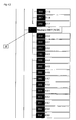
- Figur 3.1.:
- Beispiel einer Datenstruktur für einen Antrieb in seiner technischen Ausprägung als Bestandteil eines erfindungsgemäßen Datenüberwachungssystems;
- Figur 3.2.:
- Fortsetzung zu
Figur 3.1 .; - Figur 3.3.:
- Fortsetzung zu
Figur 3.2 .; - Figur 3.4.:
- Fortsetzung zu
Figur 3.3 .; - Figur 3.5.:
- Fortsetzung zu
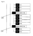
Figur 3.4 .; - Figur 4.1.:
- schematische Darstellung einer Datenstruktur einer externen SPS in ihrer hardwaretechnischen Ausprägung als Bestandteil eines erfindungsgemäßen Datenüberwachungssystems, wobei die Darstellung jener der
Figuren 3.1. bis 3.5 . entspricht; - Figur 4.2.:
- Fortsetzung zu
Figur 4.1 .; - Figur 4.3.:
- Fortsetzung zu
Figur 4.2 .; - Figur 5:
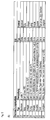
- Tabelle zur Veranschaulichung der von dem erfindungsgemäßen Datenüberwachungssystem zugelassenen Verknüpfungen von Parametertypen und Formaten mit einer externen SPS und einer externen Datenbank;
- Figur 6:
- (A) tabellarische Übersicht zur Veranschaulichung der erfindungsgemäßen Adressierung eines Speicherbereichs einer Maschinensteuerung, (B) tabellarische Darstellung zur Veranschaulichung der erfindungsgemäßen Adressierung einer externen Datenbank;
- Figur 7:
- schematische Darstellung der erfindungsgemäßen Verknüpfung von Datenkanälen mit externen Einheiten (A) am Beispiel eines Datenfelds einer technologischen Datenbank und (B) am Beispiel eines Parameters einer SPS.
- FIG. 1:
- schematic representation of a preferred embodiment of a data monitoring system according to the invention;
- FIG. 2:
- schematic representation of a relational database structure for uniform treatment of external databases and external PLC according to the invention;
- FIG. 2b:
- schematic representation of the data model for linking channel data with the memory address of an external device
- Figure 3.1 .:
- Example of a data structure for a drive in its technical form as part of a data monitoring system according to the invention;
- Figure 3.2 .:
- Continued to
Figure 3.1 . - Figure 3.3 .:
- Continued to
Figure 3.2 . - Figure 3.4 .:
- Continued to
Figure 3.3 . - Figure 3.5 .:
- Continued to
Figure 3.4 . - Figure 4.1 .:
- schematic representation of a data structure of an external PLC in its hardware specification as part of a data monitoring system according to the invention, wherein the representation of those of
Figures 3.1. to 3.5 , corresponds; - Figure 4.2 .:
- Continued to
Figure 4.1 . - Figure 4.3 .:
- Continued to
Figure 4.2 . - FIG. 5:
- Table illustrating the associations of parameter types and formats permitted by the data monitoring system according to the invention with an external PLC and an external database;
- FIG. 6:
- (A) tabular overview to illustrate the inventive addressing of a memory area a machine control, (B) tabular representation to illustrate the addressing of an external database according to the invention;
- FIG. 7:
- schematic representation of the inventive linking of data channels with external units (A) using the example of a data field of a technological database and (B) using the example of a parameter of a PLC.
Die
Das Überwachungssystem 1 ist an eine speicherprogrammierbare Steuerung (SPS) 2, und eine externe Datenbank 3 angeschlossen. Der Fachmann wird erkennen, dass diese beiden externen Einheiten nur exemplarisch zu verstehen sind. In der Praxis ist eine beliebige Anzahl von SPS 2 und/oder Datenbanken 3 an das Überwachungssystem 1 nach der Erfindung einschließbar.The
Das Überwachungssystem 1 ist außerdem über einen Blackberry-Dienst 4 zur mobilen Kommunikation mit einem mobilen Endgerät 16 verbunden, wobei das mobile Endgerät 16 als Blackberry-Client eingerichtet ist. Die SPS 2 ist über ein Anlagennetzwerk 5 nach dem Profinet-Standard und einen TCP/IP Dienst 6 an einen Kommunikationsserver 7 des erfindungsgemäßen Überwachungssystems 1 angeschlossen. Der Kommunikationsserver 7 bildet in dieser Weise das Bindeglied zwischen dem erfindungsgemäßen Überwachungssystem 1 und der Automatisierungstechnik, welche mit der SPS 2 in Verbindung steht. Bei verteilten Systemen kann der Kommunikationsserver 7 direkt neben den Automatisierungsgeräten der technischen Anlage aufgebaut werden. Denn der Kommunikationsserver 7 ist gemäß der hier beschriebenen Ausführungsform der Erfindung autark von den anderen Komponenten des Überwachungssystems 1. Insbesondere besteht keine Datenbankanbindung.The
Die Datenbank 3 kann zum Beispiel eine SAP-Datenbank oder Microsoft Access Datenbank sein. Die Datenbank 3 ist über eine Datenbankanbindung 8 und einen SQL-Server 9 ebenfalls mit dem Kommunikationsserver 7 des Überwachungssystems 1 verbunden. Die Datenbankanbindungen 8,9 sind nur beispielhaft zu verstehen. Der Fachmann wird erkennen, daß im Rahmen der Erfindung auch andere Möglichkeiten der Datenanbindung an dem Kommunikationsserver bestehen.The
Das Überwachungssystems 1 umfasst als weitere wesentliche Komponenten einen Trend-Server 10 und einen Notification-Server 11. Sowohl der Trend-Server 10 als auch der Notification-Server 11 kommuniziert bidirektional mit einer internen Schnittstelle 12 des Communication-Server 7.The
Der Trend-Server 10 dient zur Verwaltung der in einem Projekt speziell für den Trend-Server 10 konfigurierten Messwerte. Dazu zeigt der Trend-Server 10 in einem vorgegebenen Zeitintervall einen ermittelten Istwert, der über den Kommunikationsserver 7 von der Datenbank 3 oder der SPS 2 empfangen wurde, in einer Projektdatenbank 13 an. Dabei können vorkonfigurierte Parameter zur Mittelwertbestimmung oder zur Glättung des aus der SPS 2 und/oder Datenbank 3 ausgelesenen Messwerts bei der Istwertbestimmung berücksichtigt werden.The
Der Notification-Server 11 verwaltet die in einem dafür vorgesehenen Projekt speziell für den Notification-Server 11 konfigurierten digitalen Meldungen, die über den Communication-Server von der SPS 2 und/oder der Datenbank 3 empfangen wurden. Der Notification-Server dient funktional dazu, beim Eintritt bestimmter Datenereignisse eine Meldung auszugeben. Ein Datenereignis in diesem Sinne kann zum Beispiel ein Flankenwechsel des in Rede stehenden Messwerts sein. Ein derartiger Flankenwechsel wird beispielsweise im Notification-Server 11 durch den Vergleich des Altwerts mit dem Neuwert erhalten. Der Notification-Server 11 erkennt dann eine steigende bzw. fallende Flanke einer Meldung durch einen Wechsel von 0 auf 1 bzw. von 1 auf 0. Um diese Funktion zu erfüllen, liest der Notification-Server 11 des erfindungsgemäßen Überwachungssystems 1 den zugehörigen Speicherbereich der SPS 2 und/oder Datenbank 3 mittels des Communication-Server 7 aus.The
Eine vom Notification-Server 11 erzeugte Meldung 14 wird innerhalb des Überwachungssystems 1 an einen Device-Manager-Dienst 15 übermittelt. Der Device-Manager-Dienst 15 ist für die Kommunikation mit mobilen Endgeräten, insbesondere einem Blackberry-Server 4, verantwortlich. Der Device-Manager 15 fungiert somit als Bindeglied zwischen dem erfindungsgemäßen Überwachungssystem 1 und den Blackberry-Endgeräten 16. Ein Datenaustausch zwischen dem Device-Manager 15 und dem Blackberry-Dienst 4 erfolgt insbesondere über einen PUSH-Dienst 17. Dadurch werden vom Notification-Server 11 erzeugte Meldungen 14 über den Device-Manager 15 nach Erstellung unmittelbar auf den Blackberry-Client 16 übermittelt, ohne dass der Blackberry-Client 16 eine Anfrage starten muss.A
Ein weiterer wichtiger Dienst des erfindungsgemäßen Überwachungssystems 1 ist der Projektmanager-Dienst 18 sowie der Systemmanager-Dienst 19. Der Systemmanager-Dienst 19 dient im Wesentlichen zur Verbindung mit einer Systemdatenbank, wohingegen der Projektmanager-Dienst 18 im Wesentlichen zur Projektierung und Konfiguration sowie zur Kommunikation mit der Projektdatenbank 13 dient.Another important service of the
In der Systemdatenbank 20 werden die Daten abgelegt, die den projektunabhängigen Rahmen des erfindungsgemäßen Überwachungssystems 1 bilden. Dazu zählen insbesondere sämtliche Systemparameter, eine Übersicht über installierte Module und Projektdatenbanken 13, eine Benutzer-/Endgeräteverwaltung und die zentrale Lizenzierung aller Elemente. Darüber hinaus werden alle Zugriffe und Anfragen von außen in der Systemdatenbank 20 protokolliert.In the
In der Projektdatenbank 13 werden alle Daten abgelegt, die die Module bezogen auf ein Projekt benötigen, um deren Aufgabe vollständig und ohne weitere Rückfrage bei der Systemdatenbank 20 durchführen zu können. In der Projektdatenbank 13 wird somit eine spezielle Instanz der gemäß Systemdatenbank 20 verfügbaren Elemente im Sinne einer Instanzierung gebildet.In the
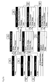
Die Projektdatenbank 13 enthält die für eine erfindungsgemäße vereinheitlichte bidirektionale Kommunikation mit der SPS 2 gleichermaßen wie mit der Datenbank 3 erforderlichen Daten. In
Die in
In der Strukturtabelle 22 werden hierarchisch alle Elemente eines Projektes abgelegt. In der als Verknüpfungstabelle dienenden Kanaltyptabelle 21 sind die verfügbaren Kanaltypen als Kombination aus Datentyp 24 und Datenformat 25 abgelegt. Um einem Strukturelement einen Kanaltyp zuzuordnen, wird diese Information in einer weiteren Verknüpfungstabelle, genannt Kanaldatenbank 23, hinzugefügt. Die Daten dieser Kanaldatenbank 23 werden, wie in
Wie diese Speicheradressen einer Datenbank oder SPS in einer Projektdatenbank 13 im einzelnen verwaltet werden, zeigt
Die unterschiedlichen mit dem Überwachungssystem 1 verbindbaren Datenbank- und SPS-Typen sind in einer Tabelle 101 definiert. Über welche Methode das Überwachungssystem 1 mit diesen externen Geräten kommunizieren kann, ergibt sich aus der Aufzählung 100 und der Verknüpfung in Tabelle 104. In der Tabelle 104 werden die verfügbaren Treiber externer Geräte 2, 3 verwaltet. Um ein externes Gerät 2, 3 im Projekt tatsächlich einzurichten, wird es als Element in der Strukturdatenbank 22 angelegt und über die Tabelle 106 mit der Treiberauswahl 104 konkretisiert. Die bezogen auf den in der Tabelle 101 abgelegten Gerätetyp verfügbaren Kanalressourcen sind vom Treiber unabhängig und in der Verknüpfungstabelle 105 abgelegt.The different database and PLC types that can be connected to the
Die Kanalressourcen ergeben sich bezogen auf den externen Gerätetyp 2, 3 aus einer Kombination zwischen Kanalgruppe gemäß Tabelle 102, z.B. Eingänge, Merker, Tabelle etc., und Kanaltyp gemäß Tabelle 23.The channel resources, based on the
Diese Kanalressourcen legen den bezogen auf das jeweilige externe Gerät 2, 3 verfügbaren adressierbaren Bereich fest, woraus sich in der Tabelle 107 der adressierte Kanal ergibt .Dieser kann paßgenau mit dem Parameter aus 23 in der Tabelle 108 zu einem adressierbaren Parameter überführt werden.These channel resources determine the addressable range available with respect to the respective
In der Kanaltyptabelle 21 sind verfügbare Kommunikationskanäle abgelegt zusammen mit Daten betreffend den Kanaltyp und das Kanalformat. Die möglichen Werte für den Kanaltyp bezieht die Kanaltyptabelle 21 aus der über eine 1:n Verknüpfung angehängte Kanaltypdatenbank 24. Mögliche Kanalformate bezieht die Kanaltyptabelle 21 aus der ebenfalls mit einer 1:n Verknüpfung angehängten Kanalformatdatenbank 25.In the channel type table 21, available communication channels are stored together with data concerning the channel type and the channel format. The possible values for the channel type are related to the channel type table 21 from the
In
Jedem dieser Kanaltypen ist ein eindeutiger Index der entsprechend überschriebenen Spalte zugeordnet. Ein Index beschreibt einen verfügbaren, vordefinierten Kanaltyp eindeutig. Es ist ersichtlich, dass ein Kanal somit gleichermaßen eine Kommunikation mit einer externen SPS 2 definieren kann, wie auch eine Kommunikation mit einer externen Datenbank 3. Die Verwaltung und Adressierung innerhalb des erfindungsgemäßen Überwachungssystems 1 ist dabei vollkommen identisch. Insbesondere liegt kein sogenannter Medienbruch vor, wie dies beim Stand der Technik der Fall ist.Each of these channel types has a unique index associated with the corresponding overwritten column. An index uniquely describes an available, predefined channel type. It can be seen that a channel can thus equally define a communication with an
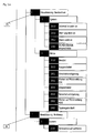
In der Strukturtabelle 22 sind innerhalb eines gegebenen Projektes in einer Ordnerhierarchie Datenstrukturen abgelegt. Die Daten sind hierarchisch erfasst und können in einer Visualisierung in einem Projektbaum angezeigt werden. Innerhalb eines Struktureintrags sind beispielsweise die für einen bestimmten Anlagenteil einer technischen Anlage möglichen und zu überwachenden Zustandsparameter hierarchisch abgelegt. Eine Struktur kann in diesem Sinne sowohl auf einen von der SPS 2 ausgelesenen Wert als auch auf einen aus der Datenbank 3 ausgelesenen Wert Bezug nehmen.In the structure table 22, data structures are stored within a given project in a folder hierarchy. The data are hierarchically recorded and can be displayed in a visualization in a project tree. Within a structural entry, for example, the state parameters that are possible and to be monitored for a specific plant section of a technical installation are stored hierarchically. In this sense, a structure can refer both to a value read out by the
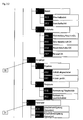
In den
Weiter ist zu erkennen, dass der Projektbaum 26 Technologiedaten 28 für einen Motor_1 enthält. Hierarchisch geordnet erhalten die Technologiedaten 28 für den Motor_1 Daten über Eingänge 29, Ausgänge 30 (vgl.
Zu den Eingängen 29 des Motors_1 28 zählen eine Störungsquittierung, ein Lampentest sowie ein Not-Aus-OK. Freigabewerte, die ebenfalls als Eingang 29 des Motors 28 definiert sind, umfassen Befehle für Einschaltfreigabe, Ausschaltfreigabe, Betriebsfreigabe, verzögerte Betriebsfreigabe, Schutzfreigabe, Einzelbetriebsfreigabe, Meldefreigabe sowie Lampenfreigabe. Ferner umfassen Eingangsbefehle als Untergruppe der Eingänge 29 einen Einschaltbefehl und einen Ausschaltbefehl. Zu den Eingängen 29 aus der Peripherie zählen gemäß
Zu den Ausgängen 30 des Motors 28 innerhalb der Struktur 26 des Antriebs zählen Werte für Einschaltverzögerung bzw. Ausschaltverzögerung in Sekunden(vgl.
Zu den Archivdaten 32, die innerhalb der Struktur 26 dem Motor_1 28 des Antriebs zugeordnet sind, zählen Informationen über den Ablauf eines Serviceintervalls, Warnungen über einen Betriebsartenkonflikt sowie Alarme folgenden Inhalts:
- keine Rückmeldung vom Hauptschütz
- Schaltbereitschaft fehlt
- Reparaturschalter offen
- Bimetall fehlt
- Schutzfreigabe gegangen
- verzögerte Betriebsfreigabe nicht erreicht
- no feedback from the main contactor
- Readiness to shift is missing
- Repair switch open
- Bimetal is missing
- Protection clearance gone
- delayed operating release not reached
Zu den Visualisierungsmodi 33 zählen in Bezug auf das System Daten darüber, ob eine Information ansteht, eine Warnung ansteht, ein Alarm ansteht und ob ein SCADA-Betrieb eingeschaltet ist. Zu den Statusmeldungen in dieser Kategorie zählen folgende Statusmeldungen:
- gestört
- ausgeschaltet
- Einschaltverzögerung
- Warten auf Rückmeldung EIN
- eingeschaltet
- Ausschaltverzögerung
- Warten auf Rückmeldung AUS
- Tippfreigabe läuft.
- disturbed
- switched off
- delay
- Waiting for feedback ON
- switched on
- Switch-off
- Waiting for feedback OFF
- Tip approval is running.
Zu den Bedienmodi 34 zählen gemäß
- Serviceintervall quittieren
- Warnungen quittieren
- Alarme quittieren
- SCADA-Betrieb einschalten
- SCADA-Betrieb ausschalten
- SCADA-Betrieb: Antrieb einschalten
- SCADA-Betrieb: Antrieb ausschalten
- Simulation: Störung auslösen.
- Acknowledge service interval
- Acknowledge warnings
- Acknowledge alarms
- Switch on SCADA operation
- Switch off SCADA operation
- SCADA operation: Switch on the drive
- SCADA operation: Switch off the drive
- Simulation: trigger fault.
Die
Wie zu erkennen in
Mit Bezug auf die
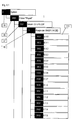
In
Dazu ist aus der Kanaltypdatenbank 24 das Element BIT und aus der Kanalformatdatenbank 25 das Element BOOL als Kombination in der Kanaltyptabelle 21 ausgewählt, um einen Kanaltyp BIT mit dem Format BOOL zu bezeichnen. Dieser Kanal hat gemäß
In entsprechender Weise ist in
Es handelt sich bei dem Kanal somit um ein Wort, diesen Wert als Dezimalzahl angezeigt werden soll.Thus, the channel is a word that should be displayed as a decimal number.
In der
- SELECT A 10.5 AS 2 FROM A WHERE Byte=10 and Bit=5
- SELECT A 10.5 AS 2 FROM A WHERE Byte = 10 and Bit = 5
Außer der hier beispielhaft erläuterten Verwendung von SQL können beispielsweise auch SQL-ähnliche Sprachen verwendet werden.Apart from the use of SQL exemplified here, for example, SQL-like languages can also be used.
Analog wird der Parameter MW 45, der das Merkerwort 45 im Format Integer enthält, mit dem achtstelligen SQL-Befehl ausgelesen.
- SELECT MW45 AS 9 FROM M WHERE Byte=45 and Bit=0
- SELECT MW45 AS 9 FROM M WHERE Byte = 45 and Bit = 0
Schließlich wird, wie in Spalte 3 der Tabelle gemäß
- SELECT DBD20 AS 15 FROM DB10 WHERE Byte=20 and Bit=0
- SELECT DBD20 AS 15 FROM DB10 WHERE Byte = 20 and Bit = 0
In
- SELECT Feld1 AS 22 FROM tbE7 WHERE
- Index_Name=Feld0 and Feld0=34
- SELECT field1 AS 22 FROM tbE7 WHERE
- Index_Name = Field0 and Field0 = 34
Ebenso dient zum Auslesen des Inhalts von Feld1 aus dem Datensatz mit dem Index TAG35622, getriggert auf Spalte Feld0 aus der Tabelle tbE7 im Format Boolean der SQL-Befehl:
- Select Feld1 AS 22 FROM tbE7 WHERE
- Index_Name=Feld0 and Feld0='TAG35622'.
- Select field1 AS 22 FROM tbE7 WHERE
- Index_Name = Field0 and Field0 = 'TAG35622'.
Man erkennt somit, dass die Adressierung der Datenbank 3 völlig nach der gleichen Syntax wie die Adressierung der SPS 2 abläuft. Dies ist dank der in der Projektdatenbank 13 abgelegten Strukturdatenbank 22 und deren Verknüpfung mit der Kanaltyptabelle 21 in der Kanalverbindungsdatenbank 23 möglich. Dabei wurde berücksichtigt, dass eine Adresse eines Parameters innerhalb einer speicherprogrammierbaren Steuerung (SPS) folgendermaßen aufgebaut ist: Gruppe, Länge, Byte, Bit.It can thus be seen that the addressing of the
Allgemein ist die einheitliche Syntax, die erfindungsgemäß zur Adressierung von Speicherbereichen verschiedenster angeschlossener Geräte verwendet wird, wie folgt:
- SELECT Cell Format_ID FROM Page WHERE.
- SELECT Cell Format_ ID FROM Page WHERE.
Cell steht dabei für den Namen des Parameters, Format_ID für die Kombination aus Typ und Format, der sich aus dem eindeutigen Relationsindex ergibt, Page für den Bereich, die Gruppe oder Tabelle, in dem der Parameter liegt, sowie Rule für die Regel, wie der Parameter eindeutig auf der Page zu adressieren ist. Cell stands for the name of the parameter, Format_ID for the combination of type and format, which is the unique one Relationsindex returns Page for the range, group, or table in which the parameter lies, as well as Rule for the rule of how to uniquely address the parameter on the Page.
In
In
In
Somit ist gemäß der Erfindung ein System und Verfahren zur Überwachung, Steuerung und Datenerfassung technischer Prozesse vorgeschlagen, welche eine vereinheitlichte Überwachung und Auswertung von externen Geräten ermöglicht. Externe Geräte können dabei sowohl speicherprogrammierbare Steuerung (SPS) als auch externe Datenbanken sein. Die gleichzeitige Überwachung von Datenbanken und SPS mit demselben System 1 ist nach der Erfindung problemlos möglich.Thus, according to the invention, a system and method for monitoring, control and data acquisition of technical processes is proposed, which enables unified monitoring and evaluation of external devices. External devices can be both programmable logic controller (PLC) and external Be databases. The simultaneous monitoring of databases and PLCs with the
Ein Datenaustausch mit den externen Datenbanken und SPS ist bidirektional möglich. Das System ist in der Lage, über den Blackberry-Dienst mit mobilen Blackberry-Clients bidirektional zu kommunizieren. Somit ist es im Rahmen der Erfindung möglich, eine technische Anlage an einem entfernten Ort über einen mobilen Blackberry-Client sowohl zu steuern als auch zu überwachen. Der Blackberry-Client kann dabei sowohl auf Daten aus externen Datenbanken als auch auf die Parameter, welche von externen SPS ausgelesen werden, zugreifen.Data exchange with the external databases and PLC is bidirectional. The system is capable of bidirectional communication with Blackberry mobile clients through the Blackberry service. Thus, within the scope of the invention it is possible to both control and monitor a technical installation at a remote location via a mobile Blackberry client. The Blackberry client can access both data from external databases as well as the parameters that are read from external PLCs.
- 11
- Überwachungssystemmonitoring system
- 22
- Speicherprogrammierbare Steuerung (SPS)Programmable logic controller (PLC)
- 33
- DatenbankDatabase
- 44
- Blackberry-DienstBlackBerry Service
- 55
- Anlagennetzwerk ProfiNETPlant network ProfiNET
- 66
- TCP/IP DienstTCP / IP service
- 77
- Kommunikationsservercommunication server
- 88th
- DatenbankanwendungDatabase application
- 99
- SQL-ServerSQL server
- 1010
- Trend-ServerTrend server
- 1111
- Notification ServerNotification Server
- 1212
- interne Schnittstelleinternal interface
- 1313
- ProjektdatenbankProject Database
- 1414
- Meldungreport
- 1515
- Device-Manager-DienstDevice Manager service
- 1616
- Blackberry-ClientBlackBerry client
- 1717
- PUSH-DienstPush Service
- 1818
- Projektmanager-DienstProject Manager Service
- 1919
- Systemmanager-DienstSystem Manager Service
- 2020
- System-DatenbankSystem database
- 2121
- KanaltyptabelleChannel type table
- 2222
- StrukturdatenbankStructure Database
- 2323
- KanalverbindungsdatenbankChannel connection database
- 2424
- Datentypdata type
- 2525
- Datenformatdata format
- 2626
- Projektbaum DatenbankProject tree database
- 2727
- Unterordner in der Projektstruktur zur Aufnahme technologischer ZusammenhängeSubfolder in the project structure for recording technological relationships
- 2828
- Technologiedatentechnology data
- 2929
- Eingängeinputs
- 3030
- Ausgängeoutputs
- 3131
- Parameterparameter
- 3232
- Archivdatenarchive
- 3333
- Visualisierungsmodusvisualization mode
- 3434
- Bedienmodioperating modes
- 3535
- Projektbaum SPSProject tree SPS
- 3636
- Unterordner in der Projektstruktur zur Aufnahme physikalischer Zusammenhänge (hardware)Subfolder in the project structure for recording physical relationships (hardware)
- 3737
- Technologiedatentechnology data
- 3838
-
Unterordner, der die physikalische Einheit 37 aufgliedert in BaugruppenSubfolder that breaks down the
physical unit 37 into assemblies - 100100
- Auflistung der verwendbaren Verbindungsprotokolle für die Kommunikation mit externen GerätenList of usable connection protocols for communication with external devices
- 101101
- Auflistung der verwendbaren ProzeßverbindungstypenList of usable process connection types
- 102102
- Auflistung der verwendbaren Kanalbereiche und/oder SpeicherbereicheList of usable channel areas and / or memory areas
- 104104
- Verbindungstabelle, in der die verwendbaren Kombinationen aus Typ und Protokoll einer Prozeßverbindung definiert sindConnection table in which the usable combinations of type and protocol of a process connection are defined
- 105105
- gültige Speicherbereiche einer Prozeßverbindung, die bei der konkreten Adressierung eines Parameters oder Peripheriekanals zur Prüfung der Verfügbarkeit verwendet werdenvalid memory areas of a process connection, which are used in the concrete addressing of a parameter or peripheral channel to check the availability
- 106106
- Verbindungstabelle, in der den verwendbaren Kombinationen aus Typ und Protokoll von Prozeßverbindungen deren gültige Speicherbereiche zugewiesen werdenConnection table, where the usable combinations of type and protocol of process connections are assigned to their valid memory areas
- 107107
- konkrete Adresse einer Prozeßverbindungconcrete address of a process connection
- 108108
- Verbindungstabelle zwischen dem technologischen Kanal und einer konkreten Adresse einer ProzeßfunktionConnection table between the technological channel and a specific address of a process function
- 110110
-
Parameter (Datenklasse 2002), dem ein Kanaltyp 23 zugewiesen werden kannParameter (data class 2002) to which a
channel type 23 can be assigned - 111111
-
Peripheriekanal (Datenklasse 3002), dem ein Kanaltyp 23 zugewiesen werden kannPeripheral channel (data class 3002) to which a
channel type 23 can be assigned
Claims (14)
Applications Claiming Priority (1)
| Application Number | Priority Date | Filing Date | Title |
|---|---|---|---|
| DE102008038968A DE102008038968A1 (en) | 2008-08-13 | 2008-08-13 | System for monitoring, control and data acquisition of technical processes |
Publications (2)
| Publication Number | Publication Date |
|---|---|
| EP2157536A2 true EP2157536A2 (en) | 2010-02-24 |
| EP2157536A3 EP2157536A3 (en) | 2010-08-11 |
Family
ID=41259699
Family Applications (1)
| Application Number | Title | Priority Date | Filing Date |
|---|---|---|---|
| EP09010313A Ceased EP2157536A3 (en) | 2008-08-13 | 2009-08-11 | System for monitoring, control and data entry of technical processes |
Country Status (3)
| Country | Link |
|---|---|
| US (1) | US20100039952A1 (en) |
| EP (1) | EP2157536A3 (en) |
| DE (1) | DE102008038968A1 (en) |
Cited By (2)
| Publication number | Priority date | Publication date | Assignee | Title |
|---|---|---|---|---|
| EP2557464A1 (en) * | 2011-08-12 | 2013-02-13 | Siemens Aktiengesellschaft | Method for operating an automation system |
| DE102012200066A1 (en) * | 2012-01-03 | 2013-07-04 | Endress + Hauser Process Solutions Ag | Method for visualization of information about e.g. containers in notebook computer in lorry in industrial plant, involves displaying information in association to display of containers, pipelines, sensors, heating device and processing unit |
Families Citing this family (6)
| Publication number | Priority date | Publication date | Assignee | Title |
|---|---|---|---|---|
| GB2471483A (en) * | 2009-06-30 | 2011-01-05 | Nokia Corp | Data type selection based on channel type |
| DE102011000823A1 (en) * | 2011-02-18 | 2012-08-23 | Dewind Europe Gmbh | Maintenance data storage of energy conversion plants |
| DE102011056171A1 (en) | 2011-12-08 | 2013-06-13 | Schad Gmbh | Control device for controlling production system in cement factory, has docking station arranged in region of machine units and provided with interface that is brought in connection with interface of operation unit |
| CN105813795A (en) * | 2013-11-12 | 2016-07-27 | 阿尔法金属公司 | Flux formulations |
| EP3862824B1 (en) * | 2020-02-04 | 2023-01-11 | Siemens Aktiengesellschaft | Interface module for configuring and parametrizing a field bus subscriber |
| JP7315088B2 (en) | 2020-02-20 | 2023-07-26 | 株式会社島津製作所 | Photoreaction evaluation device and photon number calculation method |
Citations (1)
| Publication number | Priority date | Publication date | Assignee | Title |
|---|---|---|---|---|
| DE10223725A1 (en) * | 2001-09-17 | 2003-04-03 | Fisher Rosemount Systems Inc | Process control system for use in petroleum process plant, implements software routine by receiving process data, process control data and process performance data, for performing function within plant |
Family Cites Families (28)
| Publication number | Priority date | Publication date | Assignee | Title |
|---|---|---|---|---|
| GB2263989B (en) * | 1992-02-01 | 1995-05-31 | Motorola Israel Ltd | Supervisory control and data acquisition system |
| US5568402A (en) * | 1994-04-11 | 1996-10-22 | Gse Process Solutions, Inc. | Communication server for communicating with a remote device |
| US6122514A (en) * | 1997-01-03 | 2000-09-19 | Cellport Systems, Inc. | Communications channel selection |
| US6157630A (en) * | 1998-01-26 | 2000-12-05 | Motorola, Inc. | Communications system with radio device and server |
| US6148244A (en) * | 1998-04-13 | 2000-11-14 | Intellution, Inc. | Equipment pathing and unit allocation for a process control system |
| US6289339B1 (en) * | 1999-02-19 | 2001-09-11 | Nortel Networks Limited | Method and apparatus for filtering a notification message from a database |
| US6700590B1 (en) * | 1999-11-01 | 2004-03-02 | Indx Software Corporation | System and method for retrieving and presenting data using class-based component and view model |
| US20020029097A1 (en) * | 2000-04-07 | 2002-03-07 | Pionzio Dino J. | Wind farm control system |
| US20020022969A1 (en) * | 2000-07-07 | 2002-02-21 | Berg Marc Van Den | Remote automated customer support for manufacturing equipment |
| US6643555B1 (en) * | 2000-10-10 | 2003-11-04 | Schneider Automation Inc. | Method and apparatus for generating an application for an automation control system |
| US6950851B2 (en) * | 2001-04-05 | 2005-09-27 | Osburn Iii Douglas C | System and method for communication for a supervisory control and data acquisition (SCADA) system |
| US7035877B2 (en) * | 2001-12-28 | 2006-04-25 | Kimberly-Clark Worldwide, Inc. | Quality management and intelligent manufacturing with labels and smart tags in event-based product manufacturing |
| US20030149608A1 (en) * | 2002-02-06 | 2003-08-07 | Kall Jonathan J. | Suite of configurable supply chain infrastructure modules for deploying collaborative e-manufacturing solutions |
| DE10223428A1 (en) * | 2002-05-25 | 2004-01-08 | Abb Patent Gmbh | Monitoring and control system for operation of technical processes and plants that are connected to a central server with condition monitoring capability |
| DE10235794A1 (en) * | 2002-08-05 | 2004-03-04 | Siemens Ag | System and procedure for condition-based maintenance |
| GB0228807D0 (en) * | 2002-12-11 | 2003-01-15 | Koninkl Philips Electronics Nv | Opportunistic location tracking |
| US7895191B2 (en) * | 2003-04-09 | 2011-02-22 | International Business Machines Corporation | Improving performance of database queries |
| US7685127B2 (en) * | 2003-06-04 | 2010-03-23 | Sap Ag | Database access system, method of accessing a database, and method of designing a database access system |
| US6799080B1 (en) * | 2003-06-12 | 2004-09-28 | The Boc Group, Inc. | Configurable PLC and SCADA-based control system |
| DE10343251A1 (en) * | 2003-09-17 | 2005-05-12 | Siemens Ag | HMI system with a mobile operating and monitoring device for safety-relevant operation of a technical system |
| US7392104B1 (en) * | 2003-09-24 | 2008-06-24 | Rockwell Automation Technologies, Inc. | Material reservation distribution system and method |
| US7013203B2 (en) * | 2003-10-22 | 2006-03-14 | General Electric Company | Wind turbine system control |
| US7840607B2 (en) * | 2004-08-06 | 2010-11-23 | Siemens Aktiengesellschaft | Data mart generation and use in association with an operations intelligence platform |
| US7840594B2 (en) * | 2005-01-24 | 2010-11-23 | Indusoft, Inc. | Method and system for communicating between an embedded device and relational databases |
| US20060218116A1 (en) * | 2005-03-28 | 2006-09-28 | O'hearn James E | Pass-through interface queries to populate a class-based model |
| US20070233655A1 (en) * | 2006-04-03 | 2007-10-04 | National Instruments Corporation | Graphical program representation of queries |
| DE102007026176A1 (en) * | 2007-01-04 | 2008-07-17 | Dewind Ltd. | SCADA unit |
| US7890357B2 (en) * | 2007-11-20 | 2011-02-15 | Hartford Fire Insurance Company | System and method for identifying and evaluating nanomaterial-related risk |
-
2008
- 2008-08-13 DE DE102008038968A patent/DE102008038968A1/en not_active Withdrawn
-
2009
- 2009-08-11 EP EP09010313A patent/EP2157536A3/en not_active Ceased
- 2009-08-13 US US12/540,535 patent/US20100039952A1/en not_active Abandoned
Patent Citations (1)
| Publication number | Priority date | Publication date | Assignee | Title |
|---|---|---|---|---|
| DE10223725A1 (en) * | 2001-09-17 | 2003-04-03 | Fisher Rosemount Systems Inc | Process control system for use in petroleum process plant, implements software routine by receiving process data, process control data and process performance data, for performing function within plant |
Non-Patent Citations (2)
| Title |
|---|
| "Analyse, Design und Realisierung eines webbasierten SCADA Systems mit OPC XML-DA Schnittstelle zu mehreren Soft-SPS Systemen", 20050901, 1 September 2005 (2005-09-01), pages 1 - 53, XP007918362, Retrieved from the Internet <URL:http://astro.uni-wuppertal.de/html/Theses/Barkhausen-diplom.pdf> * |
| "Data Access Custom Interface Standard", OPC DATA ACCESS CUSTOM INTERFACE SPECIFICATION 2.04,, no. Version 2.05A, 28 June 2002 (2002-06-28), pages 1 - 194, XP007918359, Retrieved from the Internet <URL:http://read.pudn.com/downloads137/doc/585853/OPCDASpecification.pdf> * |
Cited By (4)
| Publication number | Priority date | Publication date | Assignee | Title |
|---|---|---|---|---|
| EP2557464A1 (en) * | 2011-08-12 | 2013-02-13 | Siemens Aktiengesellschaft | Method for operating an automation system |
| US9563181B2 (en) | 2011-08-12 | 2017-02-07 | Siemens Aktiengesellschaft | Method for operating an automation system |
| DE102012200066A1 (en) * | 2012-01-03 | 2013-07-04 | Endress + Hauser Process Solutions Ag | Method for visualization of information about e.g. containers in notebook computer in lorry in industrial plant, involves displaying information in association to display of containers, pipelines, sensors, heating device and processing unit |
| DE102012200066B4 (en) * | 2012-01-03 | 2020-09-03 | Endress + Hauser Process Solutions Ag | Method and device for the visualization of information in a process plant |
Also Published As
| Publication number | Publication date |
|---|---|
| EP2157536A3 (en) | 2010-08-11 |
| DE102008038968A1 (en) | 2010-02-18 |
| US20100039952A1 (en) | 2010-02-18 |
Similar Documents
| Publication | Publication Date | Title |
|---|---|---|
| EP2157536A2 (en) | System for monitoring, control and data entry of technical processes | |
| EP1096348B1 (en) | Integration of a field guidance device in a plant guidance system | |
| EP0906596B1 (en) | Process automation system | |
| DE102009045386A1 (en) | Method for operating a fieldbus interface | |
| DE102007026678A1 (en) | Method for exchanging a defective field device for a new field device in a system communicating via a digital field bus, in particular an automation system | |
| DE112004000223T5 (en) | Interface module for use with a Modbus device network and Fieldbus device network | |
| EP2828713A1 (en) | Method for parameterizing a field device | |
| EP3637205A1 (en) | Image activation on an operator station client | |
| DE19614748C2 (en) | Fault diagnosis procedure | |
| EP1714197B1 (en) | Driver for field devices used in process automation technology | |
| EP4170443A1 (en) | Control device and method for switching input/output units of a control device | |
| EP2520991A1 (en) | Method for controlled intervention into the behaviour of a sub-module | |
| DE102010063164A1 (en) | Method for integrating at least one field device in a network of automation technology | |
| DE102008038501A1 (en) | Method for determining a static data structure of a field device | |
| DE10208530A1 (en) | Method for configuration and operation of peripheral devices connected to a host unit via a field bus in which the peripherals are supplied with a configuration file so that they can be directly configured by the host over the bus | |
| DE102019107401A1 (en) | SYSTEMS AND METHODS FOR MANAGING WARNINGS RELATED TO DEVICES OF A PROCESS CONTROL SYSTEM | |
| EP2713301A1 (en) | Method and system for connecting a controller for a machine to a higher level IT system | |
| EP2002316B1 (en) | Control device having an integrated machine model | |
| DE4413836A1 (en) | Connection of machine systems on to complex network | |
| EP3699704B1 (en) | System and method for validating system requirements of cyber-physical systems | |
| DE10131944A1 (en) | Processes for processing data | |
| EP3652595B1 (en) | Method and system for monitoring an automation system | |
| EP1814002A1 (en) | Data acquisition in a distributed automation system | |
| EP4213469A1 (en) | Method for establishing network communication by means of opc ua | |
| WO2008077358A1 (en) | Network of devices with an automation device and an operating device, and method for operating such a network of devices |
Legal Events
| Date | Code | Title | Description |
|---|---|---|---|
| PUAI | Public reference made under article 153(3) epc to a published international application that has entered the european phase |
Free format text: ORIGINAL CODE: 0009012 |
|
| AK | Designated contracting states |
Kind code of ref document: A2 Designated state(s): AT BE BG CH CY CZ DE DK EE ES FI FR GB GR HR HU IE IS IT LI LT LU LV MC MK MT NL NO PL PT RO SE SI SK SM TR |
|
| AX | Request for extension of the european patent |
Extension state: AL BA RS |
|
| PUAL | Search report despatched |
Free format text: ORIGINAL CODE: 0009013 |
|
| AK | Designated contracting states |
Kind code of ref document: A3 Designated state(s): AT BE BG CH CY CZ DE DK EE ES FI FR GB GR HR HU IE IS IT LI LT LU LV MC MK MT NL NO PL PT RO SE SI SK SM TR |
|
| AX | Request for extension of the european patent |
Extension state: AL BA RS |
|
| RIC1 | Information provided on ipc code assigned before grant |
Ipc: G05B 19/05 20060101ALI20100708BHEP Ipc: G06Q 10/00 20060101AFI20091116BHEP |
|
| 17P | Request for examination filed |
Effective date: 20110211 |
|
| 17Q | First examination report despatched |
Effective date: 20110503 |
|
| RAP1 | Party data changed (applicant data changed or rights of an application transferred) |
Owner name: SCHAD GMBH |
|
| STAA | Information on the status of an ep patent application or granted ep patent |
Free format text: STATUS: THE APPLICATION HAS BEEN REFUSED |
|
| 18R | Application refused |
Effective date: 20130314 |