EP2151978A1 - Mobile terminal with touch screen and method of processing data using the same - Google Patents
Mobile terminal with touch screen and method of processing data using the same Download PDFInfo
- Publication number
- EP2151978A1 EP2151978A1 EP08173023A EP08173023A EP2151978A1 EP 2151978 A1 EP2151978 A1 EP 2151978A1 EP 08173023 A EP08173023 A EP 08173023A EP 08173023 A EP08173023 A EP 08173023A EP 2151978 A1 EP2151978 A1 EP 2151978A1
- Authority
- EP
- European Patent Office
- Prior art keywords
- application
- data
- function
- mobile terminal
- touch screen
- Prior art date
- Legal status (The legal status is an assumption and is not a legal conclusion. Google has not performed a legal analysis and makes no representation as to the accuracy of the status listed.)
- Granted
Links
Images


Classifications
-
- H—ELECTRICITY
- H04—ELECTRIC COMMUNICATION TECHNIQUE
- H04M—TELEPHONIC COMMUNICATION
- H04M1/00—Substation equipment, e.g. for use by subscribers
- H04M1/72—Mobile telephones; Cordless telephones, i.e. devices for establishing wireless links to base stations without route selection
- H04M1/724—User interfaces specially adapted for cordless or mobile telephones
- H04M1/72403—User interfaces specially adapted for cordless or mobile telephones with means for local support of applications that increase the functionality
- H04M1/72445—User interfaces specially adapted for cordless or mobile telephones with means for local support of applications that increase the functionality for supporting Internet browser applications
-
- G—PHYSICS
- G06—COMPUTING; CALCULATING OR COUNTING
- G06F—ELECTRIC DIGITAL DATA PROCESSING
- G06F3/00—Input arrangements for transferring data to be processed into a form capable of being handled by the computer; Output arrangements for transferring data from processing unit to output unit, e.g. interface arrangements
- G06F3/01—Input arrangements or combined input and output arrangements for interaction between user and computer
- G06F3/048—Interaction techniques based on graphical user interfaces [GUI]
- G06F3/0484—Interaction techniques based on graphical user interfaces [GUI] for the control of specific functions or operations, e.g. selecting or manipulating an object, an image or a displayed text element, setting a parameter value or selecting a range
- G06F3/0486—Drag-and-drop
-
- G—PHYSICS
- G06—COMPUTING; CALCULATING OR COUNTING
- G06F—ELECTRIC DIGITAL DATA PROCESSING
- G06F3/00—Input arrangements for transferring data to be processed into a form capable of being handled by the computer; Output arrangements for transferring data from processing unit to output unit, e.g. interface arrangements
- G06F3/01—Input arrangements or combined input and output arrangements for interaction between user and computer
- G06F3/048—Interaction techniques based on graphical user interfaces [GUI]
- G06F3/0487—Interaction techniques based on graphical user interfaces [GUI] using specific features provided by the input device, e.g. functions controlled by the rotation of a mouse with dual sensing arrangements, or of the nature of the input device, e.g. tap gestures based on pressure sensed by a digitiser
- G06F3/0488—Interaction techniques based on graphical user interfaces [GUI] using specific features provided by the input device, e.g. functions controlled by the rotation of a mouse with dual sensing arrangements, or of the nature of the input device, e.g. tap gestures based on pressure sensed by a digitiser using a touch-screen or digitiser, e.g. input of commands through traced gestures
-
- H—ELECTRICITY
- H04—ELECTRIC COMMUNICATION TECHNIQUE
- H04M—TELEPHONIC COMMUNICATION
- H04M1/00—Substation equipment, e.g. for use by subscribers
- H04M1/26—Devices for calling a subscriber
- H04M1/27—Devices whereby a plurality of signals may be stored simultaneously
- H04M1/274—Devices whereby a plurality of signals may be stored simultaneously with provision for storing more than one subscriber number at a time, e.g. using toothed disc
- H04M1/2745—Devices whereby a plurality of signals may be stored simultaneously with provision for storing more than one subscriber number at a time, e.g. using toothed disc using static electronic memories, e.g. chips
- H04M1/27467—Methods of retrieving data
- H04M1/27475—Methods of retrieving data using interactive graphical means or pictorial representations
-
- H—ELECTRICITY
- H04—ELECTRIC COMMUNICATION TECHNIQUE
- H04M—TELEPHONIC COMMUNICATION
- H04M1/00—Substation equipment, e.g. for use by subscribers
- H04M1/72—Mobile telephones; Cordless telephones, i.e. devices for establishing wireless links to base stations without route selection
- H04M1/724—User interfaces specially adapted for cordless or mobile telephones
- H04M1/72403—User interfaces specially adapted for cordless or mobile telephones with means for local support of applications that increase the functionality
- H04M1/7243—User interfaces specially adapted for cordless or mobile telephones with means for local support of applications that increase the functionality with interactive means for internal management of messages
Abstract
Description
- Pursuant to 35 U.S.C. § 119(a), this application claims the benefit of earlier filing date and right of priority to Korean Application No.
10-2008-0077841, filed on August 8, 2008 - The present invention relates to a mobile terminal with a touch screen. Specifically, a mobile terminal comprising a touch screen allowing simple access between an application and data, and a method of processing data using the same.
- As more functions are added to terminals such as personal computers, laptop computers, and cellular phones, the terminals become multimedia players with multiple functions such as capturing pictures or videos, playing music, displaying videos, providing games, and receiving broadcasting programs.
- Terminals may be divided into mobile terminals and stationary terminals. Mobile terminals may be classified into handheld terminals and vehicle mount terminals according to the portability of the terminals.
- As terminals provide more complex and various functions, a menu structure associated with the functions becomes complicated. Thus, a user must navigate through various complicated menus to access a desired function. Accordingly, efforts have been made to simplify the complicated menu structure to provide a convenient user interface (UI). Specifically, it is an object of one embodiment of the present invention to provide a simple user interface in a mobile terminal with a small screen.
- Features and advantages of the invention will be set forth in the description which follows, and in part will be apparent from the description, or may be learned by practice of the invention. The objectives and other advantages of the invention will be realized and attained by the structure particularly pointed out in the written description and claims hereof as well as the appended drawings.
- In accordance with an embodiment, a method of processing data in a mobile terminal with a touch screen is presented. The method includes
simultaneously displaying a first application and a data list including at least one data item in predetermined regions on the touch screen, selecting at least one data item from the data list, moving the selected at least one data item to the region displaying the first application, and using the selected at least one data item to execute a function provided by the first application in response to the moved selected at least one data item. - In one feature, the region displaying the first application comprises a plurality of function fields for respectively providing different functions, the selected at least one data item is moved to one of the plurality of function fields, and the first application executes a function provided by the function field to which the selected at least one data item was moved. Furthermore, at least one of the region where the first application is displayed or the region where the data list is displayed is movable on the touch screen. Additionally, the data list is managed by a second application different from the first application. Finally, a plurality of data lists are respectively displayed in predetermined positions.
- In another feature, the first application is a video telephony application for transmitting data to a video telephony recipient. Additionally, the data list comprises at least one of a text, a still image, a moving image, a phone number, or an Internet address.
- In yet another feature, the first application is an message transmitting application comprising at least one function for designating a message source or a message destination, a function for inputting a message, or a function for attaching a file. Additionally, the data list comprises at least one of a text, a still image, a moving image, a phone number, or an Internet address.
- In still yet another feature, the first application is a web browsing application and comprises at least one function for a web search or a function for inputting an Internet addresses. Additionally, the data list comprises at least one of a text or an Internet address.
- In accordance with an embodiment a mobile terminal with a touch screen is presented. The mobile terminal includes a touch screen, a memory storing at least one application and at least one data list including at least one data item, and a controller simultaneously displaying a first application and the data list in predetermined positions on the touch screen and using at least one data item selected from the data list to execute a function provided by the first application when the selected at least one data item is moved to the region where the first application is displayed.
- These and other embodiments will also become readily apparent to those skilled in the art from the following detailed description of the embodiments having reference to the attached figures, the invention not being limited to any particular embodiment disclosed.
- The above and other aspects, features, and advantages of the present invention will become more apparent upon consideration of the following description of preferred embodiments, taken in conjunction with the accompanying drawing figures, wherein:
-
FIG. 1 is a block diagram of a mobile terminal according to an embodiment of the present invention. -
FIG. 2A is a front perspective view of a handheld terminal according to an embodiment of the present invention. -
FIG. 2B is a rear perspective view of the handheld terminal shown inFIG. 2A according to an embodiment of the present invention. -
FIGS. 3A and3B are front views of a handheld terminal for explaining an operation of the handheld terminal according to an embodiment of the present invention. -
FIG. 4 illustrates an example of a proximity depth of a proximity sensor. -
FIG. 5 illustrates a flow chart of a method of processing data in a mobile terminal with a touch screen according to a first embodiment of the present invention. -
FIG. 6 illustrates an example of displaying an application region with a data list according to the first embodiment of the present invention. -
FIG. 7 illustrates a flow chart of a method of processing data in a mobile terminal with a touch screen according to a second embodiment of the present invention. -
FIGS. 8A ,8B ,8C and8D illustrate an example to which the present invention is applied in a video telephony application. -
FIGS. 9A ,9B ,9C and9D illustrate an example to which the present invention is applied in the video telephony application. -
FIG. 10 illustrates a flow chart of a method of processing data in a mobile terminal with a touch screen according to a third embodiment of the present invention. -
FIGS. 11A through 11E illustrate an example to which the present invention is applied in a messaging application. -
FIG. 12 illustrates a flow chart of a method of processing data in a mobile terminal with a touch screen according to a fourth embodiment of the present invention. -
FIGS. 13A through 13E illustrate an example to which the present invention is applied in the video telephony application. -
FIG. 14 illustrates a flow chart of a method of processing data in a mobile terminal with a touch screen according to a fifth embodiment of the present invention. -
FIGS. 15A through 15E ,16A, and 16B illustrate an example to which the present invention is applied for a plurality of web pages. - In the following detailed description, reference is made to the accompanying drawing figures which form a part hereof, and which show by way of illustration specific embodiments of the invention. It is to be understood by those of ordinary skill in this technological field that other embodiments may be utilized, and structural, electrical, as well as procedural changes may be made without departing from the scope of the present invention. Wherever possible, the same reference numbers will be used throughout the drawings to refer to the same or similar parts.
- Hereinafter, a mobile terminal relating to the present invention will be described below in more detail with reference to the accompanying drawings. In the following description, suffixes "module" and "unit" are given to components of the mobile terminal in consideration of only facilitation of description and do not have meanings or functions discriminated from each other.
- The mobile terminal described in the specification may include a cellular phone, a smart phone, a laptop computer, a digital broadcasting terminal, personal digital assistants (PDA), a portable multimedia player (PMP), or a navigation system.
-
FIG. 1 illustrates a block diagram of amobile terminal 100 according to an embodiment of the present invention. Themobile terminal 100 may include aradio communication unit 110, an audio/video (A/V)input unit 120, auser input unit 130, asensing unit 140, anoutput unit 150, amemory 160, aninterface unit 170, acontroller 180, and apower supply 190. The components illustrated inFIG. 1 are not essential parts and the number of components included in the mobile terminal may vary. - The components of the mobile terminal will now be described in detail.
- The
radio communication unit 110 may include at least one module that enables radio communication between themobile terminal 100 and a radio communication system, or between themobile terminal 100 and a network in which themobile terminal 100 is located. For example, theradio communication unit 110 may include abroadcasting receiving module 111, amobile communication module 112, awireless Internet module 113, a localarea communication module 114, and aposition information module 115. - The
broadcast receiving module 111 receives a broadcast signal and broadcast associated information from an external broadcast managing entity via a broadcast channel. - The broadcast channel may include a satellite channel or a terrestrial channel. The broadcast managing entity may be a system which transmits a broadcast signal or broadcast associated information.
- Examples of broadcast associated information include information associated with a broadcast channel, a broadcast program, or a broadcast service provider. For example, broadcast associated information may include an electronic program guide (EPG) of digital multimedia broadcasting (DMB) or electronic service guide (ESG) of digital video broadcast-handheld (DVB-H). In this example, the broadcasting related information may be received by the
mobile communication module 112. - The
broadcast receiving module 111 may receive broadcast signals transmitted from various types of broadcast systems. By nonlimiting example, such broadcasting systems include digital multimedia broadcasting-terrestrial (DMB-T), digital multimedia broadcasting-satellite (DMB-S), digital video broadcast-handheld (DVB-H), the data broadcasting system known as media forward link only (MediaFLO®), and integrated services digital broadcast-terrestrial (ISDB-T). - The
broadcast receiving module 111 may also receive multicast signals. Data received by thebroadcast receiving module 111 may be stored in a suitable device, such as thememory 160. - The
mobile communication module 112 transmits and receives wireless signals to and from one or more network entities, such as a base station or a Node-B. The wireless signals may represent audio, video, multimedia, control signaling, or data. - The
wireless Internet module 113 provides Internet access for the terminal 100. Thewireless Internet module 113 may be internally or externally coupled to the terminal 100. The wireless Internet techniques may include, but are not limited to, Wireless LAN (WLAN) (Wi-Fi), wireless broadband (Wibro), world interoperability for microwave access (Wimax), and high speed downlink packet access (HSDPA). - The local
area communication module 114 facilitates short-range communications. Suitable technologies for implementing the localarea communication module 114 include radio frequency identification (RFID), infrared data association (IrDA), ultra-wideband (UWB), as well at the networking technologies commonly referred to as Bluetooth™ and ZigBee™.. - The
position information module 115 identifies and obtains the location of the terminal 100. Theposition information module 115 may be implemented using global positioning system (GPS) components which cooperate with associated satellites and network components. - The audio/video (A/V)
input unit 120 provides audio or video signal inputs to the terminal 100. The A/V input unit 120 may include acamera 121 and amicrophone 122. Thecamera 121 receives and processes image frames of still pictures or video. The processed image frames or video may be displayed on adisplay unit 151. - The
microphone 122 receives an external audio signal while the terminal 100 is in a particular mode, such as a phone call mode, a recording mode, or a voice recognition mode. The audio signal is processed and converted into digital data. The terminal 100 and A/V input unit 120 may include assorted noise removing algorithms to remove noise generated in the course of receiving the external audio signal. - Data generated by the A/
V input unit 120 may be stored in thememory 160, utilized by theoutput unit 150, or transmitted via one or more modules ofcommunication unit 110. The terminal 100 may include two ormore microphones 122 orcameras 121. - The
user input unit 130 generates input data in response to user manipulation of an associated input device or devices. Examples of such devices include a keypad, a dome switch, a touchpad, a jog wheel, and a jog switch. - The
sensing unit 140 provides status measurements for various aspects of the terminal 100. For example, the sensing unit may detect an open and close state of the terminal 100, relative positioning of components of the terminal, a change of position of the terminal, a change of position of a component of the terminal, a presence or absence of user contact with the terminal, orientation of the terminal, or acceleration or deceleration of the terminal. Thesensing unit 140 may also sense the presence or absence of power provided by thepower supply 190 and the presence or absence of a connection between theinterface unit 170 and an external device. Thesensing unit 140 may also include a proximity sensor. - The
interface unit 170 may act as a passage for supplying themobile terminal 100 with a power from a cradle or delivering various command signals input from the cradle if themobile terminal 110 is connected to an external cradle. Each of the various command signals input from the cradle or the power may operate as a signal enabling themobile terminal 100 to recognize that it is correctly loaded in the cradle. - The
output unit 150 outputs information associated with the terminal 100. Thedisplay 151 is typically implemented to display information associated with the terminal 100. For example, thedisplay 151 may provide a graphical user interface which includes information associated with a phone call if the terminal is operating in a phone call mode. Thedisplay 151 may display images which are associated with various modes, such as a video call mode or a photographing mode. - The
display 151 may be configured as a touch screen working in cooperation with theinput unit 130, in one embodiment of the present invention. This configuration allows thedisplay 151 to function both as an output device and an input device. The touch screen may be in the form of a touch film, a touch sheet and a touch pad, for example. - The
display 151 may be implemented using known display technologies such as a liquid crystal display (LCD), a thin film transistor-liquid crystal display (TFT-LCD), an organic light-emitting diode display (OLED), a flexible display, or a three-dimensional display. - The display unit may be of a transparent type or a light transmission type. The transparent display includes a transparent liquid crystal display. The rear structure of the
display unit 151 may also be of the light transmission type. According to this structure, a user may see an object located behind the body of themobile terminal 100 through an area of the body of themobile terminal 100, which is occupied by thedisplay unit 151. - The terminal 100 may include one or
more displays 151. An example of a two-display embodiment is one in which onedisplay 151 is configured as an internal display which is viewable when the terminal 100 is in an opened position and a second display configured as an external display which is viewable in both the open and closed positions. - The touch sensor may be constructed such that it converts a variation in pressure applied to a specific area of the
display unit 151 or a variation in capacitance generated at a specific area of thedisplay unit 151 into an electric input signal. The touch sensor may sense the pressure of a touch in addition to the position and area of a touch. - When an input is applied to the touch screen, a signal corresponding to the input is transmitted to a touch controller. The touch controller processes the signal and transmits data corresponding to the processed signal to the
controller 180. Accordingly, thecontroller 180 may detect a touched area of thedisplay 151.
Theproximity sensor 141 may be provided within or around the touchscreen. The proximity sensor detects an object approaching a prescribed detecting surface or a presence or non-presence of an object existing around itself using an electromagnetic power or infrared rays without mechanical contact. - The proximity sensor may include a transmission type photo-electric sensor, a direct reflection type photo-electric sensor, a mirror reflection type photo-electric sensor, a high-frequency oscillating proximity sensor, a capacitive proximity sensor, a magnetic proximity sensor, or an infrared proximity sensor.
- A capacitive touch screen may be constructed such that proximity of a pointer may be detected via a variation in an electric field according to the proximity of the pointer. In this example, the touch screen may be classified as a proximity sensor.
- For clarity and convenience of explanation, an action for enabling the pointer approaching the touchscreen to be recognized as placed on the touchscreen is referred to as a "proximity touch" and an action of enabling the pointer to actually come into contact with the touchscreen is referred to as a "contact touch". A "proximity touch point" refers to a point on the touch screen which the pointer perpendicularly corresponds with the touch screen.
- The proximity sensor may sense a proximity touch pattern and a proximity touch action. For example, the proximity sensor may sense a proximity touch distance, a proximity touch direction, a proximity touch velocity, a proximity touch time, a proximity touch position, or a proximity touch moving state. Information associated with the sensed proximity touch action and proximity touch pattern may be displayed on the touch screen.
-
Fig. 1 further shows theoutput unit 150 having anaudio output module 152. Theaudio output module 152 may be implemented using one or more speakers, buzzers, or other audio producing devices. - The
audio output module 152 functions in various modes including a call-receiving mode, a call-placing mode, a recording mode, a voice recognition mode, or a broadcast reception mode. Theaudio output module 152 outputs audio relating to a particular function, such as a call notification, a message notification, or a error notification. - The
output unit 150 is further shown having analarm 153, which may be used to output a signal for indicating generation of an event of themobile terminal 100. Examples of events generated in the mobile terminal include receiving a call signal, receiving of a message, input of a key signal, or input of touch, for example. - The
alarm 153 may output signals in forms different from video signals or audio signals, for example, a signal for indicating generation of an event via vibration. The video signals or the audio signals may be output via thedisplay unit 151 or theaudio output module 152. - The
output unit 150 is further shown having ahaptic module 154, which may generate various haptic effects such as a vibration. The haptic module may control the intensity and pattern of the generated vibration. For example, different vibrations may be combined and output or sequentially output. - The
haptic module 154 may generate a variety of haptic effects, such as, the feeling of pins contacting a user's skin, a jet force or sucking force, rubbing a user's skin, a user's contact with an electrode, an electrostatic force, or variations in temperature. - The
haptic module 154 may also allow a user to feel haptic effects via kinesthetic sense of the user's fingers or arms. Themobile terminal 100 may include more than onehaptic module 154 according to constitution of the mobile terminal. - The
memory 160 may store various types of data to support the processing, control, or storage requirements of the terminal 100. Examples of such data include program instructions for applications operating on the terminal, contact data, phonebook data, messages, pictures, or video. - The
memory 160 shown inFig. 1 may be implemented using any type of volatile and non-volatile memory or storage devices. Such devices may include random access memory (RAM), static random access memory (SRAM), electrically erasable programmable read-only memory (EEPROM), erasable programmable read-only memory (EPROM), programmable read-only memory (PROM), read-only memory (ROM), magnetic memory, flash memory, magnetic or optical disk, card-type memory, or other similar memory or data storage device. Themobile terminal 100 may operate in relation to a web storage performing the storing function of thememory 160 on the Internet. - The
interface unit 170 may be implemented to connect the terminal with an external device. External devices include wired and wireless headphones, external chargers, power supplies, storage devices configured to store data, or microphones. Theinterface unit 170 may be configured using a wired and wireless data port, a memory card socket, audio input and output ports (I/O), or video I/O ports. Additionally, theinterface unit 170 may act as a passage for supplying themobile terminal 100 with a power supply. - The
interface unit 170 may also receive a user identification module (UIM). A UIM may include a chip that stores information for authenticating the authority to use themobile terminal 100 and may include a subscriber identity module (SIM) and a universal subscriber identity module (USIM). A user identification module may be manufactured in the form of a smart card. - The
controller 180 controls the overall operations of the terminal 100. For example, thecontroller 180 performs the control and processing associated with voice calls, data communications, video calls, camera operations, and recording operations. - The
controller 180 may include amultimedia module 181 which provides multimedia playback. Themultimedia module 181 may be configured as part of thecontroller 180 or may be implemented as a separate component. - Moreover, the
controller 180 is able to perform a pattern recognizing process for recognizing a writing input and a picture drawing input carried out on the touchscreen as characters or images. - The
power supply 190 provides power to the various components of the terminal 100. The power provided may be internal power or external power. - Various embodiments described herein may be implemented in a computer-readable medium using computer software. The various embodiments may also be implemented in hardware.
- A hardware implementation may be implemented using one or more application specific integrated circuits (ASICs), digital signal processors (DSPs), digital signal processing devices (DSPDs), programmable logic devices (PLDs), field programmable gate arrays (FPGAs), processors, controllers, microcontrollers, microprocessors, or other electronic units designed to perform the functions described herein. Some embodiments are implemented by
controller 180. - A software implementation of the embodiments described herein may be implemented with separate software modules, such as procedures and functions, each of which perform one or more of the functions and operations described herein. The software code may be implemented with a software application written in any suitable programming language and may be stored in the
memory 160 for execution by thecontroller 180 or a processor. -
FIG. 2A illustrates a perspective view of a terminal 100 according to an embodiment of the present invention. - The terminal 100 may be implemented in a variety of different configurations. Examples of such configurations include folder-type, slide-type, bar-type, rotational-type, swing-type, and swivel-type terminals comprising at least two bodies that are relatively movably combined.
- The terminal body includes a case, such as, a housing or a cover, forming the exterior of the terminal 100. In the present embodiment, the case may be divided into a
front case 101 and arear case 102. Various electronic components are arranged in the space formed between thefront case 101 and therear case 102. At least one middle case (not shown) may be additionally arranged between thefront case 101 and therear case 102. - The cases may be formed of plastics via injection molding or made of a metal material such as stainless steel (STS) or titanium (Ti).
- The
display unit 151, theaudio output unit 152, thecamera 121, the user input unit 130 (not shown), 131, and 132, themicrophone 122, and theinterface 170 may be arranged in the terminal body, specifically, in thefront case 101. - The
display unit 151 may be placed on thefront case 101. Theaudio output unit 152 and thecamera 121 may be placed in proximity to one end of thedisplay unit 151, theuser input unit 131 and themicrophone 122 may be located at the end of thedisplay unit 151 which is opposite to theaudio output unit 152. Theuser input unit 132 and theinterface unit 170 may be arranged on the sides of thefront case 101 and therear case 102. - The
user input unit 130 may receive commands for controlling the operation of thehandheld terminal 100 and may include a plurality ofinput units input units -
Input units input unit 131 may receive commands such as start, stop, and scroll and theinput unit 132 may receive commands for controlling the volume of a sound output from theaudio output unit 152 or conversion of thedisplay unit 151 to a touch recognition mode, for example. -
FIG. 2B illustrates a rear perspective view of the handheld terminal shown inFIG. 2A according to an embodiment of the present invention. - As illustrated in
FIG. 2A , acamera 125 may be additionally attached to therear case 102. Thecamera 125 has a photographing direction opposite to that of thecamera 121. Thecamera 121 of thefront case 101 andcamera 125 of therear case 102 may have the same or different capabilities. - For example, the
camera 121 may operate with a relatively lower resolution than thecamera 125. Such an arrangement works well during a video conference in which reverse link bandwidth capabilities may be limited. The relatively higher resolution of thecamera 125 of therear case 102 is useful for obtaining higher quality pictures. Thecameras - A
flash bulb 123 and amirror 124 are additionally arranged in proximity to thecamera 125. Theflash bulb 123 may illuminate an object when thecamera 125 takes a picture of the object. Themirror 124 is useful for assisting a user to position thecamera 125 in a self-portrait mode. - The
rear case 102 also includes anaudio output module 153 configured as a speaker. Theaudio output module 152 of thefront case 101 and theaudio output module 153 ofrear case 102 may cooperate to provide stereo output. Moreover, either or both of theaudio output modules - A broadcasting
signal receiving antenna 116 may be additionally attached to the side of the terminal body in addition to an antenna for telephone calls. Theantenna 116 functions in cooperation with thebroadcast receiving module 111. Theantenna 116 may be fixed or configured to retract into therear case 102. - The
power supply 190 provides power to the terminal 100. Thepower supply 190 may be detachably mounted to the terminal. - A
touch pad 135 may be additionally attached to therear case 102. Thetouch pad 135 may be of a light transmission type similar to thedisplay unit 151. For example, thetouch pad 135 may simultaneously output information displayed on thedisplay unit 151. Additionally, the information output via both sides of thedisplay unit 151 may be controlled via thetouch pad 135. Additionally, thetouch pad 135 may display information which is different from the information displayed on thedisplay unit 151. - The
touch pad 135 may operate in connection with thedisplay unit 151 of thefront case 101. Additionally, thetouch pad 135 may also be located in parallel with thedisplay unit 151 or behind thedisplay unit 151. Finally, the size of thetouch panel 135 may be identical to or smaller than thedisplay unit 151. - The operations of the
display unit 151 and thetouch pad 135 will now be described with reference toFIGS. 3A and3B .FIGS. 3A and3B illustrate front views of the terminal 100 according to an embodiment of the present invention. - The
display unit 151 may display various types of visual information in the form of characters, numerals, symbols, graphics, or icons. At least one of the characters, numerals, symbols, graphic, or icons may be displayed in a predetermined arrangement, such as a keypad. The keypad displayed on thedisplay unit 151 may be referred to as a "soft key". -
FIG. 3A illustrates that touch applied to a soft key is input via the front side of the terminal body. Thedisplay unit 151 may be operated via the entire display area. Alternatively, thedisplay unit 151 may be divided into a plurality of regions. Additionally, thedisplay unit 151 may be constructed such that the plurality of regions interoperate. - For example, an
output window 151a and aninput window 151b may be, respectively, displayed in upper and lower parts of thedisplay unit 151. Theinput window 151b may displaysoft keys 151c that represent numerals used to input numbers such as telephone numbers. A numeral corresponding to the touched soft key is displayed on theoutput window 151a when a soft key 151c is touched. Additionally, a connection for a call corresponding to a telephone number displayed on theoutput window 151a is attempted when the user operates the input unit 131-1. -
FIG. 3B illustrates a user input via thetouch pad 135 located on the rear side of the terminal body.FIG. 3B illustrates a landscape orientation of the terminal body whileFIG. 3A illustrates a portrait orientation of the terminal body. Thedisplay unit 151 may be constructed such that an output image is converted according to the direction in which the terminal body is located. -
FIG. 3B illustrates the operation of the handheld terminal in a text input mode. Thedisplay unit 151 displays anoutput window 135a and aninput window 135b. A plurality ofsoft keys 135c may display at least one of characters, symbols, and numerals. Thesoft keys 135c may be displayed in theinput window 135b. Thesoft keys 135c may be arranged in the form of "QWERTY" keys. - Characters, numerals, and symbols corresponding to the touched
soft keys 135c are displayed on theoutput window 135a whensoft keys 135c are touched via thetouch pad 135. Touch input via thetouch pad 135 allows for thesoft keys 135c to have a greater visibility as compared to touch input via thedisplay unit 151. For example, objects located behind the terminal body may be viewed with the naked eye, and thus touch input may be performed more correctly when thedisplay unit 151 and thetouch pad 135 are transparent. - The
display unit 151 or thetouch pad 135 may be constructed such that touch input may be received via a scroll input. The user may scroll thedisplay unit 151 or thetouch pad 135 to move an object displayed on thedisplay unit 151, for example, a cursor or a pointer located on an icon. Furthermore, the finger moving path may be visually displayed on thedisplay unit 151 when a finger moves on thedisplay unit 151 or thetouch pad 135. - A specific function of the terminal may be executed if the
display unit 151 and thetouch pad 135 are simultaneously touched for a predetermined period of time. The specific function may include activation or inactivation of thedisplay unit 151 or thetouch pad 135, for example. - The proximity sensor described with reference to
FIG. 1 will now be explained in more detail with reference toFIG. 4. Fig. 4 illustrates a conceptual view for a proximity depth of the proximity sensor. - As shown in
FIG. 4 , when a pointer such as a user's finger approaches the touch screen, the proximity sensor senses the approach and may output a proximity signal. - The proximity sensor may be constructed such that it outputs a proximity signal according to the distance between the pointer approaching the touch screen and the touch screen (referred to as "proximity depth").
- The distance in which the proximity signal is output when the pointer approaches the touch screen is referred to as a detection distance. The proximity depth may be known by using a plurality of proximity sensors having different detection distances and comparing proximity signals respectively output from the proximity sensors.
-
FIG. 4 shows the section of the touch screen in which proximity sensors may sense three proximity depths. Proximity sensors may be capable of sensing various levels of proximity depths, such as less than three or greater than four. - Specifically, a pointer is recognized as a contact touch when the pointer comes into contact with the touch screen (DO). The pointer is recognized as a proximity touch of a first proximity depth when the pointer is located within a distance D1 from the touch screen. The pointer is recognized as a proximity touch of a second proximity depth when the pointer is located in a range between the distance D1 and a distance D2 from the touch screen, The pointer is recognized as a proximity touch of a third proximity depth when the pointer is located in a range between the distance D2 and a distance D3 from the touch screen. The pointer is recognized as a canceled proximity touch when the pointer is located beyond the distance D3 from the touch screen.
- Accordingly, the
controller 180 may recognize the proximity touch as various input signals according to the proximity distance and the proximity position of the pointer with respect to the touch screen. Thecontroller 180 may perform various operation controls according to the input signals. - Embodiments of the prevent invention will now be explained. For convenience of explanation it is assumed that the
display unit 151 is a touch screen in the present invention. Furthermore, a touch includes both a proximity touch and direct touch. -
FIG. 5 illustrates a flow chart of a method of processing data in a mobile terminal with a touch screen according to a first embodiment of the present invention.FIG. 6 illustrates an example of displaying an application region with a data list according to the first embodiment of the present invention. The method of processing data in a mobile terminal with a touch screen and the operation of the mobile terminal for achieving the method according to the first embodiment of the present invention will now be explained in detail with reference toFIGS. 1 ,5 , and6 . - The
controller 180 displays a first application with a data list in predetermined regions on the display unit 151 (S 100). - The data list may comprise a list of at least one of text, still images, and moving images. For example, the data list may relate to texts having the same attribute. Furthermore, the data list may relate to still images and moving images having at least two attributes. Additionally, the text of the data list may include an Internet address of a specific web site, such as, a uniform resource locator (URL).
- A plurality of different data lists may be displayed. For example, a data list with respect to still images and a data list with respect to moving images may be simultaneously displayed on the
display unit 151. The different data lists may be, respectively, displayed in predetermined positions. - As illustrated in
FIG. 6 , thedisplay unit 151 displays a phonebook contact list 300 (S101).Reference numerals icon 301 may represent a messaging application for transmitting and receiving SMS or MMS messages. Accordingly, if a user touches and drags theicon 301 toward the center of the screen (S102), amessaging application 310 is scrolled and displayed on the display unit 151 (S103). The user may touch and drag theicon 301 to move themessaging application 310 to a desired position. - Examples of the first application include a video telephony application, a messaging application for transmitting and receiving messages, or a web browsing application.
- The region in which the first application is displayed may include a plurality of function regions for, respectively, providing different functions. For example, the region in which the messaging application is displayed may include at least one of a source input field for designating a source of the message, a destination input field for designating a destination of the message, a message input field for inputting content for the message, and an attachment field for attaching a file to the message.
- Referring to
FIG. 5 , the user may touch and select at least one data item, or a group of data items, in the data list displayed on the display unit 151 (S110). The data list or specific data included in the data list may be moved and displayed on thedisplay unit 151. Furthermore, the data list may be managed by a second application which is different from the first application. For example, the data list may be managed by a second application according to an attribute of the data list. For example, the data list may be managed by a phonebook application, an image application, or a messaging application. - The user may touch the selected data item and move the selected item to the region in which the first application is displayed (S120). Step S120 corresponds to an operation of dragging-and-dropping the selected at least one data item to the first application region. The selected data item may be moved to one of the plurality of function regions if the first application region includes a plurality of function regions.
- The
controller 180 executes the function of the first application using the selected data item (S130). Thecontroller 180 may execute a function provided by the function region to which the data item is moved to one of the plurality of function regions if the first application region includes the plurality of function regions. - The present invention may be applied to various embodiments according to the type of the first application. The various embodiments of the present invention will now be explained according to the type of the first application.
-
FIG. 7 illustrates a flow chart for a method of processing data in a mobile terminal with a touch screen according to a second embodiment of the present invention. In the second embodiment of the present invention, the first application corresponds to a video telephony application.FIGS. 8A ,8B, 8C , and8D illustrate an example to which the present invention is applied in the video telephony application.FIGS. 9A ,9B ,9C , and9D illustrate another example to which the present invention is applied in the video telephony application. The method of processing data in a mobile terminal according to the second embodiment of the present invention will now be explained in detail with reference toFIGS. 1, 7, 8A through 8D, and 9A through 9D . - The
controller 180 may simultaneously display avideo telephony application 200 and a data list (S200). A user may select specific data from the data list (S210) and drag-and-drop the selected data to the region in which thevideo telephony application 200 is displayed (S220). Thecontroller 180 may then transmit the selected data to a video telephony recipient (S230). - Referring to
FIGS. 1 ,8A ,8B, 8C , and8D , thecontroller 180 may simultaneously display thevideo telephony application 200 and animage list region 210 on the display unit 151 (S200). Theimage list region 210 displays animage list 211 including a plurality ofimages image list region 210 may display ascroll bar 212 when all the images included in theimage list 211 cannot be simultaneously displayed in theimage list region 210. The user may operate thescroll bar 212 to access a desired image. - The region in which the
video telephony application 200 is displayed may include arecipient image field 202 displaying an image of a recipient for a video telephony call, auser image field 203 displaying an image of the user of themobile terminal 100, and anicon field 201 displaying icons representing various functions. The image displayed in therecipient image field 202 may be received from the recipient via themobile communication module 112 or thewireless Internet module 113, for example. Additionally, the image displayed in theuser image field 203 may be obtained via thecamera 121. - As illustrated in
FIG. 8B , a user may touch theimage 211b that is intended to be transmitted to a video telephony recipient from the image list 211 (S210). The user may then drag-and-drop the selectedimage 211b to the user image field 203 (S220), as illustrated inFIG. 8C . - The
controller 180 may transmit the selectedimage 211 to the recipient (S230) after step S220, as illustrated inFIG. 8D . Thecontroller 180 may replace the image of the user, displayed in theuser image field 203, with the selectedimage 211b. Furthermore, thecontroller 180 may display a message informing the user that the selectedimage 211b has been transmitted on thedisplay unit 151 while continuously displaying the image of the user in theuser image field 203. - Referring to
FIGS. 9A ,9B ,9C , and9D , thecontroller 180 may simultaneously display thevideo telephony application 200 and aphonebook 230 in predetermined regions on the display unit 151 (S200). Thephonebook 230 displays aphonebook list 231 including a plurality of phonebook data items. Thephonebook 230 may display thescroll bar 212. The user may operate thescroll bar 212 to access desired phonebook data. - The user may touch and select the phonebook data that the user wants to transmit to a video telephony recipient from the phonebook list 231 (S210). The user may then drag-and-drop the phonebook data to the user image field 203 (S220).
- As illustrated in
FIGS. 9B and 9C , the user selects phonebook data corresponding to "Albert" and drags-and-drops the phonebook data to theuser image field 203. Thecontroller 180 may then transmit the selected phonebook data to the recipient (S230). Thecontroller 180 may replace the user image displayed in theuser image field 203 with the selected phonebook data, as shown inFIG. 9D . Furthermore, thecontroller 180 may display a message informing the user that the selected phonebook data has been transmitted to the recipient on thedisplay unit 151 while continuously displaying the image of the user in theuser image field 203. -
FIG. 10 illustrates a flow chart for a method of processing data in a mobile terminal with a touch screen according to a third embodiment of the present invention. In the third embodiment of the present invention, the first application is associated with a messaging application.FIGS. 11A through 11E illustrate an example to which the present invention is applied in the messaging application. The method of processing data in a mobile terminal according to the third embodiment of the present invention will now be explained in detail with reference toFIGS. 1 ,10 , and11A through 11E . - The
controller 180 simultaneously displays amessaging application 240, aphonebook 230, and afile list 250 in predetermined regions on the display unit 151 (S300). The region in which themessaging application 240 is displayed includes adestination field 241, anattachment file field 242 and amessage composition field 243. Furthermore, thedisplay unit 151 displays thephonebook 230 including aphonebook list 231. Thefile list 250 may include various files. For example, as illustrated inFIG. 11A , a picture list may be used as thefile list 250. - A user selects a specific item from the
phonebook 230 and drags-and-drops the selected specific item to the messaging application region 240 (S310). For example, as illustrated inFIG. 11B , the user may touch and select "Albert" and then drag-and-drop "Albert" to themessaging application region 240. The user may drag-and-drop the specific item to a predetermined point in themessaging application region 240 or a point included in a region to which the specific item may be input. - For example, the
controller 180 may check an attribute of the specific item dragged-and-dropped to themessaging application region 240 and determine that the specific item is data that may be used in therecipient field 241. - Furthermore, the controller may consider only the specific item dragged-and-dropped to the
messaging application region 240 as data that may be used in therecipient field 241. For example, thecontroller 180 may analyze the attribute of the specific item dragged-and-dropped to therecipient field 241 and output a message informing the user that the specific item cannot be used in therecipient field 241 when it is determined that that the specific item is not the data that may be used in therecipient field 241. - The
controller 180 designates the selected specific item as a message recipient (S320). For example, as illustrated inFIG. 11C , "Albert" may be displayed in therecipient field 241. - As illustrated in
FIG. 11D , the user may touch and select a specific file from thefile list 250 and drag-and-drop the selected file to the messaging application region 240 (S330). The user may drag-and-drop the selected file to various points, as described above with respect to step S210. Furthermore, thecontroller 180 may output a message that informs the user when a specific file dragged-and-dropped to theattachment file field 241 cannot be attached to a message due to a problem or size of the specific file. - The controller may attach the selected file to the message (S340). For example, as illustrated in
FIG. 11E , a file name "P080801" indicating the selected file is displayed in theattachment file field 242. -
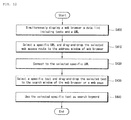
FIG. 12 illustrates a flow chart for a method of processing data in a mobile terminal with a touch screen according to a fourth embodiment of the present invention. In the fourth embodiment, the first application is associated with a web browser.FIGS. 13A through 13E show an example to which the present invention is applied in the video telephony application. The method of processing data in a mobile terminal according to the fourth embodiment of the present invention will now be explained in detail with reference toFIGS. 1 ,12 , and13A through 13E . - The
controller 180 may simultaneously display aweb browser 260, atext list 271, and adata list 272 including a Universal Resource Locator (URL)list 272 in predetermined regions on the display unit 151 (S400). TheURL list 272 may display the full URL, such as www.daum.net or display a title associated with a URL, such as "Google". Thetext list 271 and theURL list 272 may be previously stored by a user or received via theradio communication unit 110 or theinterface 170. - As illustrated in
FIG. 13B , the user may touch and select a specific URL from theURL list 272 and then drag-and-drop the selected URL to anaddress window 261 of the web browser 260 (S410). Theweb browser 260 may then connect to the selected web access route (S420). Referring toFIG. 13C , theweb browser 260 may access a web site "http://www.google.co.kr" corresponding to "Google" to display a web page provided by "Google" as the user drags-and-drops "Google", for example. Theweb browser 260 may connect to the selected URL via thewireless Internet module 113. - As illustrated in
FIG. 13D , the user may touch and select a specific text from the text list 171 and drag-and-drop the selected text to asearch window 262 of theweb browser 260 or asearch window 263 provided by the connected web site (S430). Additionally, as illustrated inFIG. 13E , theweb browser 260 may use the selected text as a search keyword for web search (S440). -
FIG. 14 illustrates a flow chart for a method of processing data in a mobile terminal with a touch screen according to a fifth embodiment of the present invention.FIGS. 15A through 15E, 16A, and 16B illustrate an example to which the present invention is applied for a plurality of web pages. The method of processing data in a mobile terminal according to the fifth embodiment of the present invention will now be explained in detail with reference toFIGS. 1, 14, 15A through 15E, 16A, and 16B . - The
controller 180 controls a web browser to perform a web search using a specific keyword in a first web page (S500). Thecontroller 180 controls the web browser to execute the web search using the keyword used in step S500 in a second web page (S510). Search results obtained in steps S500 and S510 are respectively referred to as first and second search results. The operations of steps S500 and S510 are exemplified with reference toFIGS. 15A through 15E . -
FIG. 15A illustrates an example of a display when a first web site and a second web site are accessed. For example, the first web site provides adisplay 270 for search via "Naver" and the second web site provides adisplay 280 for search via "Google" (S600). The first web site provides afirst search window 271 for performing a web search using a search engine provided by the first web site and the second web site provides asecond search window 272 for performing a web search using a search engine provided by the second web site. Thedisplay unit 151 displays amemo box 290 in which a text list including at least one text that may be used as a search keyword is displayed, as illustrated inFIG. 15A . - As illustrated in
FIG. 15B , a user may touch and select "Dalai Lama" from thememo box 290 and drag-and-drop "Dalai Lama" to the first search window 271 (S610). The first web site may perform a web search using "Dalai Lama" as a keyword and provide the first search result 272 (S620), as illustrated inFIG. 15C . - As illustrated in
FIG. 15D , a user may touch and select "Dalai Lama" and drag-and-drop "Dalai Lama" to the second search window 281 (S630). The second web site may perform a web search using "Dalai Lama" as a keyword and provide the second search result 282 (S420), as illustrated inFIG. 15E . - The first web site and the second web site may use different search engines. Accordingly, the
first search result 272 and thesecond search result 282 may be different from each other. - As illustrated in
FIG. 16A , a user may touch and select the region where the second web page is displayed and drag-and-drop the selected second web page to the region where the first web page is displayed (S630). Thecontroller 180 may display the union or intersection of thefirst search result 272 and thesecond search result 282 on the display unit 151 (S640). The union corresponds to the sum of thefirst search result 272 and thesecond search result 282 and the intersection corresponds to common results in thefirst search result 272 and thesecond search result 282. - As illustrated in
FIG. 16B , thecontroller 180 may display theunion 273 of thefirst search result 272 and thesecond search result 282 in theregion 270 where the first web page is displayed (S641). Furthermore, thecontroller 180 may display theintersection 274 of thefirst search result 272 and thesecond search result 282 in theregion 270 wherein the first web page is displayed (S642). Additionally, theunion 273 or theintersection 274 may be displayed in theregion 280 where the second web page is displayed or a predetermined region of thedisplay unit 151. For example, thecontroller 180 may display theunion 273 in theregion 270 where the first web page is displayed and display theintersection 274 in theregion 280 wherein the second web page is displayed (S643). - The above described data processing method in a mobile terminal with a touch screen according to the present invention may be written as computer programs and may be implemented in general-use digital computers that execute the programs using a computer readable recording medium.
- The data processing method in a mobile terminal with a touch screen according to the present invention may be executed through software. In this case, constituent means of the present invention are code segments carrying out required works. Programs or code segments may be stored in a processor readable medium and transmitted according to computer data signals combined with carriers in a transmission medium or a communication network.
- The computer readable recording medium includes all types of recording devices storing data readable by computer systems. Examples of the computer readable recording medium include ROM, RAM, CD-ROM, DVD±ROM, DVD-RAM, magnetic tapes, floppy disks, hard disks, and optical data storage devices. The computer readable recording medium may also be distributed over networked computer systems so that the computer readable code is stored and executed in a distributed fashion.
- While the present invention has been particularly shown and described with reference to exemplary embodiments thereof, it will be understood by those of ordinary skill in the art that various changes in form and details may be made therein without departing from the spirit and scope of the present invention as defined by the following claims.
Claims (14)
- A method of processing data in a mobile terminal with a touch screen, the method comprising:simultaneously displaying a first application and a data list including at least one data item in predetermined regions on the touch screen;selecting at least one data item from the data list;moving the selected at least one data item to the region displaying the first application; andusing the selected at least one data item to execute a function provided by the first application in response to the moved selected at least one data item.
- The method of claim 1, wherein the region displaying the first application comprises a plurality of function fields for respectively providing different functions, the selected at least one data item is moved to one of the plurality of function fields, and the first application executes a function provided by the function field to which the selected at least one data item was moved.
- The method of claim 1, wherein the first application comprises at least one of a video telephony application for transmitting data to a video telephony recipient, an message transmitting application comprising at least one function for designating a message source or a message destination, a function for inputting a message, or a function for attaching a file, or a web browsing application comprising at least one function for a web search or a function for inputting an Internet addresses.
- The method of claim 3, wherein the data list comprises at least one of a text, a still image, a moving image, a phone number, or an Internet address.
- The method of claim 1, wherein at least one of the region where the first application is displayed or the region where the data list is displayed is movable on the touch screen.
- The method of claim 1, wherein the data list is managed by a second application different from the first application.
- The method of claim 1, wherein a plurality of data lists are respectively displayed in predetermined positions.
- A mobile terminal with a touch screen, the mobile terminal comprising:a touch screen;a memory storing at least one application and at least one data list including at least one data item; anda controller simultaneously displaying a first application and the data list in predetermined positions on the touch screen and using at least one data item selected from the data list to execute a function provided by the first application when the selected at least one data item is moved to the region where the first application is displayed.
- The mobile terminal of claim 8, wherein the region displaying the first application includes a plurality of function fields for respectively providing different functions, the selected at least one data item is moved to one of the plurality of function fields, and the first application executes a function provided by the function field to which the selected at least one data item was moved.
- The mobile terminal of claim 8, wherein the first application comprises at least one of a video telephony application for transmitting data to a video telephony recipient, an message transmitting application comprising at least one function for designating a message source or a message destination, a function for inputting a message, or a function for attaching a file, or a web browsing application comprising at least one function for a web search or a function for inputting an Internet addresses.
- The mobile terminal of claim 10, wherein the data list comprises at least one of a text, a still image, a moving image, a phone number, or an Internet address.
- The mobile terminal of claim 8, wherein at least one of the region where the first application is displayed or the region where the data list is displayed is movable on the touch screen.
- The mobile terminal of claim 8, wherein the data list is managed by a second application different from the first application.
- The mobile terminal of claim 8, wherein the controller a plurality of data lists respectively having predetermined display positions on the touch screen.
Applications Claiming Priority (1)
| Application Number | Priority Date | Filing Date | Title |
|---|---|---|---|
| KR1020080077841A KR101568351B1 (en) | 2008-08-08 | 2008-08-08 | Mobile Terminal With Touch Screen And Method Of Processing Data Using Same |
Publications (2)
| Publication Number | Publication Date |
|---|---|
| EP2151978A1 true EP2151978A1 (en) | 2010-02-10 |
| EP2151978B1 EP2151978B1 (en) | 2014-06-04 |
Family
ID=41138125
Family Applications (1)
| Application Number | Title | Priority Date | Filing Date |
|---|---|---|---|
| EP08173023.6A Not-in-force EP2151978B1 (en) | 2008-08-08 | 2008-12-29 | Mobile terminal with touch screen and method of processing data using the same |
Country Status (3)
| Country | Link |
|---|---|
| US (1) | US9973612B2 (en) |
| EP (1) | EP2151978B1 (en) |
| KR (1) | KR101568351B1 (en) |
Cited By (5)
| Publication number | Priority date | Publication date | Assignee | Title |
|---|---|---|---|---|
| EP2339443A1 (en) * | 2009-12-24 | 2011-06-29 | Samsung Electronics Co., Ltd. | Method and system for operating application of a touch device with touch-based input interface |
| CN103260087A (en) * | 2012-02-20 | 2013-08-21 | 三星电子株式会社 | Display apparatus and control method thereof |
| US9767605B2 (en) | 2012-02-24 | 2017-09-19 | Nokia Technologies Oy | Method and apparatus for presenting multi-dimensional representations of an image dependent upon the shape of a display |
| US9804734B2 (en) | 2012-02-24 | 2017-10-31 | Nokia Technologies Oy | Method, apparatus and computer program for displaying content |
| EP3149981A4 (en) * | 2014-05-31 | 2018-02-28 | Samsung Electronics Co., Ltd. | Electronic device and method of executing application |
Families Citing this family (24)
| Publication number | Priority date | Publication date | Assignee | Title |
|---|---|---|---|---|
| US20130124531A1 (en) * | 2010-09-08 | 2013-05-16 | Walter Bachtiger | Systems for extracting relevant and frequent key words from texts and their presentation in an auto-complete function of a search service |
| KR101650948B1 (en) * | 2009-11-17 | 2016-08-24 | 엘지전자 주식회사 | Method for displaying time information and display apparatus thereof |
| KR101585692B1 (en) * | 2009-11-17 | 2016-01-14 | 엘지전자 주식회사 | Method for displaying contents information |
| KR101714781B1 (en) * | 2009-11-17 | 2017-03-22 | 엘지전자 주식회사 | Method for playing contents |
| US9436280B2 (en) * | 2010-01-07 | 2016-09-06 | Qualcomm Incorporated | Simulation of three-dimensional touch sensation using haptics |
| KR20110100414A (en) * | 2010-03-04 | 2011-09-14 | 삼성전자주식회사 | Digital apparatus and method for displaying user interface for transmitting contents |
| JP5434767B2 (en) * | 2010-04-16 | 2014-03-05 | ソニー株式会社 | Information processing apparatus, information processing method, and program thereof |
| KR101701836B1 (en) * | 2010-07-05 | 2017-02-02 | 엘지전자 주식회사 | Mobile terminal and Method for controlling message transmission thereof |
| KR20120019531A (en) * | 2010-08-26 | 2012-03-07 | 삼성전자주식회사 | Method and apparatus for providing graphic user interface in mobile terminal |
| KR101811743B1 (en) | 2010-09-09 | 2018-01-25 | 삼성전자주식회사 | Multimedia apparatus and Method for providing contents thereof |
| KR101859102B1 (en) * | 2011-09-16 | 2018-05-17 | 엘지전자 주식회사 | Mobile terminal and control method for mobile terminal |
| CN103713752B (en) * | 2012-09-28 | 2016-10-05 | 联想(北京)有限公司 | A kind of orientation recognition method and apparatus |
| US9778776B2 (en) * | 2012-07-30 | 2017-10-03 | Beijing Lenovo Software Ltd. | Method and system for processing data |
| KR101957173B1 (en) | 2012-09-24 | 2019-03-12 | 삼성전자 주식회사 | Method and apparatus for providing multi-window at a touch device |
| US20140351717A1 (en) * | 2013-05-24 | 2014-11-27 | Facebook, Inc. | User-Based Interactive Elements For Content Sharing |
| KR101459552B1 (en) | 2013-06-19 | 2014-11-07 | 주식회사 케이티 | Method for displaying object in layout region of device and the device |
| US10866714B2 (en) * | 2014-02-13 | 2020-12-15 | Samsung Electronics Co., Ltd. | User terminal device and method for displaying thereof |
| US10747416B2 (en) | 2014-02-13 | 2020-08-18 | Samsung Electronics Co., Ltd. | User terminal device and method for displaying thereof |
| US10712918B2 (en) | 2014-02-13 | 2020-07-14 | Samsung Electronics Co., Ltd. | User terminal device and displaying method thereof |
| CN104133629A (en) * | 2014-07-10 | 2014-11-05 | 深圳市中兴移动通信有限公司 | Double-screen interaction method and mobile terminal |
| CN105549843A (en) * | 2015-12-03 | 2016-05-04 | 深圳市金立通信设备有限公司 | Application display method and terminal device |
| KR20180048142A (en) * | 2016-11-02 | 2018-05-10 | 엘지전자 주식회사 | Mobile terminal and method for controlling the same |
| CN107589893A (en) * | 2017-09-21 | 2018-01-16 | 上海联影医疗科技有限公司 | A kind of data load method, device and terminal |
| CN110908552B (en) * | 2019-10-11 | 2021-08-10 | 广州视源电子科技股份有限公司 | Multi-window operation control method, device, equipment and storage medium |
Citations (3)
| Publication number | Priority date | Publication date | Assignee | Title |
|---|---|---|---|---|
| WO1998048554A1 (en) * | 1997-04-23 | 1998-10-29 | Northern Telecom Limited | Calling line identification with drag and drop capability |
| US20050235037A1 (en) * | 2004-03-25 | 2005-10-20 | Heiko Tropartz | Method and computer for sending an electronic document |
| EP1739533A2 (en) * | 2005-06-20 | 2007-01-03 | LG Electronics Inc. | Apparatus and method for processing data of a mobile terminal |
Family Cites Families (20)
| Publication number | Priority date | Publication date | Assignee | Title |
|---|---|---|---|---|
| US6606101B1 (en) * | 1993-10-25 | 2003-08-12 | Microsoft Corporation | Information pointers |
| US5897637A (en) * | 1997-03-07 | 1999-04-27 | Apple Computer, Inc. | System and method for rapidly identifying the existence and location of an item in a file |
| US6195094B1 (en) * | 1998-09-29 | 2001-02-27 | Netscape Communications Corporation | Window splitter bar system |
| US7076730B1 (en) * | 1998-12-10 | 2006-07-11 | Intellinet, Inc. | Electronic mail software with modular integrated authoring/reading software components |
| US7444374B1 (en) * | 1998-12-10 | 2008-10-28 | Michelle Baker | Electronic mail software with modular integrated authoring/reading software components including methods and apparatus for controlling the interactivity between mail authors and recipients |
| US20040001094A1 (en) * | 2002-06-28 | 2004-01-01 | Johannes Unnewehr | Automatic identification of drop zones |
| US7234117B2 (en) * | 2002-08-28 | 2007-06-19 | Microsoft Corporation | System and method for shared integrated online social interaction |
| US20050149496A1 (en) * | 2003-12-22 | 2005-07-07 | Verity, Inc. | System and method for dynamic context-sensitive federated search of multiple information repositories |
| US8140975B2 (en) * | 2005-01-07 | 2012-03-20 | Apple Inc. | Slide show navigation |
| US8635548B2 (en) * | 2005-03-18 | 2014-01-21 | International Business Machines Corporation | Configuring a page for drag and drop arrangement of content artifacts in a page development tool |
| US8028245B2 (en) * | 2005-05-24 | 2011-09-27 | Microsoft Corporation | Method and system for operating multiple web pages with anti-spoofing protection |
| US7783985B2 (en) * | 2006-01-04 | 2010-08-24 | Citrix Systems, Inc. | Systems and methods for transferring data between computing devices |
| US20070157129A1 (en) * | 2006-01-05 | 2007-07-05 | International Business Machines Corporation | System and method for search queries and results preview using drag and drop interface |
| US7450003B2 (en) * | 2006-02-24 | 2008-11-11 | Yahoo! Inc. | User-defined private maps |
| US20070276811A1 (en) * | 2006-05-23 | 2007-11-29 | Joshua Rosen | Graphical User Interface for Displaying and Organizing Search Results |
| US10416838B2 (en) * | 2006-12-11 | 2019-09-17 | Oath Inc. | Graphical messages |
| US20090170492A1 (en) * | 2007-12-28 | 2009-07-02 | Apple Inc. | User-programmed automated communications |
| US8640040B2 (en) * | 2008-03-28 | 2014-01-28 | Sprint Communications Company L.P. | Persistent event-management access in a mobile communications device |
| US20090288012A1 (en) * | 2008-05-18 | 2009-11-19 | Zetawire Inc. | Secured Electronic Transaction System |
| US8631079B2 (en) * | 2008-06-20 | 2014-01-14 | Microsoft Corporation | Displaying a list of file attachments associated with a message thread |
-
2008
- 2008-08-08 KR KR1020080077841A patent/KR101568351B1/en not_active IP Right Cessation
- 2008-12-29 EP EP08173023.6A patent/EP2151978B1/en not_active Not-in-force
- 2008-12-29 US US12/345,427 patent/US9973612B2/en not_active Expired - Fee Related
Patent Citations (3)
| Publication number | Priority date | Publication date | Assignee | Title |
|---|---|---|---|---|
| WO1998048554A1 (en) * | 1997-04-23 | 1998-10-29 | Northern Telecom Limited | Calling line identification with drag and drop capability |
| US20050235037A1 (en) * | 2004-03-25 | 2005-10-20 | Heiko Tropartz | Method and computer for sending an electronic document |
| EP1739533A2 (en) * | 2005-06-20 | 2007-01-03 | LG Electronics Inc. | Apparatus and method for processing data of a mobile terminal |
Cited By (15)
| Publication number | Priority date | Publication date | Assignee | Title |
|---|---|---|---|---|
| US8510655B2 (en) | 2009-12-24 | 2013-08-13 | Samsung Electronics Co., Ltd. | Method and system for operating application of a touch device with touch-based input interface |
| US9122365B2 (en) | 2009-12-24 | 2015-09-01 | Samsung Electronics Co., Ltd. | Method and system for operating application of a touch device with touch-based input interface |
| EP2339443A1 (en) * | 2009-12-24 | 2011-06-29 | Samsung Electronics Co., Ltd. | Method and system for operating application of a touch device with touch-based input interface |
| US9886171B2 (en) | 2009-12-24 | 2018-02-06 | Samsung Electronics Co., Ltd. | Method and system for operating application of a touch device with touch-based input interface |
| US9959018B2 (en) | 2012-02-20 | 2018-05-01 | Samsung Electronics Co., Ltd. | Display apparatus and control method thereof |
| CN103260087A (en) * | 2012-02-20 | 2013-08-21 | 三星电子株式会社 | Display apparatus and control method thereof |
| EP2629188A1 (en) * | 2012-02-20 | 2013-08-21 | Samsung Electronics Co., Ltd | Display apparatus and control method for drag and drop externally stored data to separately externally stored application to trigger the processing of the data by the application |
| US10788960B2 (en) | 2012-02-20 | 2020-09-29 | Samsung Electronics Co., Ltd. | Display apparatus and control method for processing content data based on user input |
| CN103260087B (en) * | 2012-02-20 | 2019-04-26 | 三星电子株式会社 | Display device and its control method |
| US9804734B2 (en) | 2012-02-24 | 2017-10-31 | Nokia Technologies Oy | Method, apparatus and computer program for displaying content |
| US9767605B2 (en) | 2012-02-24 | 2017-09-19 | Nokia Technologies Oy | Method and apparatus for presenting multi-dimensional representations of an image dependent upon the shape of a display |
| US9924024B2 (en) | 2014-05-31 | 2018-03-20 | Samsung Electronics Co., Ltd. | Electronic device and method of executing application |
| EP3149981A4 (en) * | 2014-05-31 | 2018-02-28 | Samsung Electronics Co., Ltd. | Electronic device and method of executing application |
| US10320965B2 (en) | 2014-05-31 | 2019-06-11 | Samsung Electronics Co., Ltd. | Electronic device and method of executing application |
| US10666787B2 (en) | 2014-05-31 | 2020-05-26 | Samsung Electronics Co., Ltd. | Electronic device and method of executing application |
Also Published As
| Publication number | Publication date |
|---|---|
| KR20100019024A (en) | 2010-02-18 |
| US9973612B2 (en) | 2018-05-15 |
| KR101568351B1 (en) | 2015-11-20 |
| US20100037167A1 (en) | 2010-02-11 |
| EP2151978B1 (en) | 2014-06-04 |
Similar Documents
| Publication | Publication Date | Title |
|---|---|---|
| EP2151978B1 (en) | Mobile terminal with touch screen and method of processing data using the same | |
| KR101609162B1 (en) | Mobile Terminal With Touch Screen And Method Of Processing Data Using Same | |
| KR101451667B1 (en) | Terminal and method for controlling the same | |
| US8219152B2 (en) | Mobile terminal and control method thereof | |
| KR101557358B1 (en) | Method for inputting a string of charaters and apparatus thereof | |
| KR101576292B1 (en) | The method for executing menu in mobile terminal and mobile terminal using the same | |
| KR101626621B1 (en) | Method for controlling data in mobile termina having circle type display unit and mobile terminal thereof | |
| KR101561703B1 (en) | The method for executing menu and mobile terminal using the same | |
| EP2189887B1 (en) | Terminal and method for assigning shortcuts for internet adresses | |
| US8775954B2 (en) | Mobile terminal to display a plurality of graphic user interfaces | |
| KR101693690B1 (en) | Mobile terminal and control method thereof | |
| KR101667577B1 (en) | Mobile terminal and method for controlling displaying thereof | |
| KR20110058117A (en) | Method for displaying data in mobile terminal having touch screen and mobile termimnal thereof | |
| KR101609388B1 (en) | Mobile terminal for displaying three-dimensional menu and control method using the same | |
| KR20110013606A (en) | Method for executing menu in mobile terminal and mobile terminal thereof | |
| KR20120136698A (en) | Mobile device and control method for the same | |
| KR101615983B1 (en) | Mobile terminal and method of controlling thereof | |
| KR101980702B1 (en) | Mobile terminal and method for controlling thereof | |
| KR101560837B1 (en) | Method for executing application in mobile terminal and mobile terminal using the same | |
| KR101681586B1 (en) | Terminal and method for controlling the same | |
| KR101693379B1 (en) | The method for displaying menu and mobile termianl using the same | |
| KR101559789B1 (en) | Mobile terminal and method for displaying thereof | |
| KR101498050B1 (en) | A mobile telecommunication device and an interfacing method using the same | |
| KR101677632B1 (en) | Mobile terminal and event information managing method threrof | |
| KR101564111B1 (en) | Method for executing item in mobile terminal and mobile terminal thereof |
Legal Events
| Date | Code | Title | Description |
|---|---|---|---|
| PUAI | Public reference made under article 153(3) epc to a published international application that has entered the european phase |
Free format text: ORIGINAL CODE: 0009012 |
|
| 17P | Request for examination filed |
Effective date: 20081229 |
|
| AK | Designated contracting states |
Kind code of ref document: A1 Designated state(s): AT BE BG CH CY CZ DE DK EE ES FI FR GB GR HR HU IE IS IT LI LT LU LV MC MT NL NO PL PT RO SE SI SK TR |
|
| AX | Request for extension of the european patent |
Extension state: AL BA MK RS |
|
| 17Q | First examination report despatched |
Effective date: 20111107 |
|
| REG | Reference to a national code |
Ref country code: DE Ref legal event code: R079 Ref document number: 602008032543 Country of ref document: DE Free format text: PREVIOUS MAIN CLASS: H04M0001725000 Ipc: H04M0001274500 |
|
| GRAP | Despatch of communication of intention to grant a patent |
Free format text: ORIGINAL CODE: EPIDOSNIGR1 |
|
| RIC1 | Information provided on ipc code assigned before grant |
Ipc: G06F 3/0486 20130101ALI20131128BHEP Ipc: H04M 1/725 20060101ALI20131128BHEP Ipc: H04M 1/2745 20060101AFI20131128BHEP |
|
| INTG | Intention to grant announced |
Effective date: 20131211 |
|
| GRAS | Grant fee paid |
Free format text: ORIGINAL CODE: EPIDOSNIGR3 |
|
| GRAA | (expected) grant |
Free format text: ORIGINAL CODE: 0009210 |
|
| AK | Designated contracting states |
Kind code of ref document: B1 Designated state(s): AT BE BG CH CY CZ DE DK EE ES FI FR GB GR HR HU IE IS IT LI LT LU LV MC MT NL NO PL PT RO SE SI SK TR |
|
| REG | Reference to a national code |
Ref country code: GB Ref legal event code: FG4D |
|
| REG | Reference to a national code |
Ref country code: CH Ref legal event code: EP |
|
| REG | Reference to a national code |
Ref country code: AT Ref legal event code: REF Ref document number: 671657 Country of ref document: AT Kind code of ref document: T Effective date: 20140615 |
|
| REG | Reference to a national code |
Ref country code: IE Ref legal event code: FG4D |
|
| REG | Reference to a national code |
Ref country code: DE Ref legal event code: R096 Ref document number: 602008032543 Country of ref document: DE Effective date: 20140717 |
|
| REG | Reference to a national code |
Ref country code: AT Ref legal event code: MK05 Ref document number: 671657 Country of ref document: AT Kind code of ref document: T Effective date: 20140604 |
|
| REG | Reference to a national code |
Ref country code: NL Ref legal event code: VDEP Effective date: 20140604 |
|
| PG25 | Lapsed in a contracting state [announced via postgrant information from national office to epo] |
Ref country code: FI Free format text: LAPSE BECAUSE OF FAILURE TO SUBMIT A TRANSLATION OF THE DESCRIPTION OR TO PAY THE FEE WITHIN THE PRESCRIBED TIME-LIMIT Effective date: 20140604 Ref country code: LT Free format text: LAPSE BECAUSE OF FAILURE TO SUBMIT A TRANSLATION OF THE DESCRIPTION OR TO PAY THE FEE WITHIN THE PRESCRIBED TIME-LIMIT Effective date: 20140604 Ref country code: NO Free format text: LAPSE BECAUSE OF FAILURE TO SUBMIT A TRANSLATION OF THE DESCRIPTION OR TO PAY THE FEE WITHIN THE PRESCRIBED TIME-LIMIT Effective date: 20140904 Ref country code: GR Free format text: LAPSE BECAUSE OF FAILURE TO SUBMIT A TRANSLATION OF THE DESCRIPTION OR TO PAY THE FEE WITHIN THE PRESCRIBED TIME-LIMIT Effective date: 20140905 Ref country code: CY Free format text: LAPSE BECAUSE OF FAILURE TO SUBMIT A TRANSLATION OF THE DESCRIPTION OR TO PAY THE FEE WITHIN THE PRESCRIBED TIME-LIMIT Effective date: 20140604 |
|
| REG | Reference to a national code |
Ref country code: LT Ref legal event code: MG4D |
|
| PG25 | Lapsed in a contracting state [announced via postgrant information from national office to epo] |
Ref country code: AT Free format text: LAPSE BECAUSE OF FAILURE TO SUBMIT A TRANSLATION OF THE DESCRIPTION OR TO PAY THE FEE WITHIN THE PRESCRIBED TIME-LIMIT Effective date: 20140604 Ref country code: SE Free format text: LAPSE BECAUSE OF FAILURE TO SUBMIT A TRANSLATION OF THE DESCRIPTION OR TO PAY THE FEE WITHIN THE PRESCRIBED TIME-LIMIT Effective date: 20140604 Ref country code: LV Free format text: LAPSE BECAUSE OF FAILURE TO SUBMIT A TRANSLATION OF THE DESCRIPTION OR TO PAY THE FEE WITHIN THE PRESCRIBED TIME-LIMIT Effective date: 20140604 Ref country code: HR Free format text: LAPSE BECAUSE OF FAILURE TO SUBMIT A TRANSLATION OF THE DESCRIPTION OR TO PAY THE FEE WITHIN THE PRESCRIBED TIME-LIMIT Effective date: 20140604 |
|
| PG25 | Lapsed in a contracting state [announced via postgrant information from national office to epo] |
Ref country code: RO Free format text: LAPSE BECAUSE OF FAILURE TO SUBMIT A TRANSLATION OF THE DESCRIPTION OR TO PAY THE FEE WITHIN THE PRESCRIBED TIME-LIMIT Effective date: 20140604 Ref country code: ES Free format text: LAPSE BECAUSE OF FAILURE TO SUBMIT A TRANSLATION OF THE DESCRIPTION OR TO PAY THE FEE WITHIN THE PRESCRIBED TIME-LIMIT Effective date: 20140604 Ref country code: SK Free format text: LAPSE BECAUSE OF FAILURE TO SUBMIT A TRANSLATION OF THE DESCRIPTION OR TO PAY THE FEE WITHIN THE PRESCRIBED TIME-LIMIT Effective date: 20140604 Ref country code: CZ Free format text: LAPSE BECAUSE OF FAILURE TO SUBMIT A TRANSLATION OF THE DESCRIPTION OR TO PAY THE FEE WITHIN THE PRESCRIBED TIME-LIMIT Effective date: 20140604 Ref country code: PT Free format text: LAPSE BECAUSE OF FAILURE TO SUBMIT A TRANSLATION OF THE DESCRIPTION OR TO PAY THE FEE WITHIN THE PRESCRIBED TIME-LIMIT Effective date: 20141006 Ref country code: EE Free format text: LAPSE BECAUSE OF FAILURE TO SUBMIT A TRANSLATION OF THE DESCRIPTION OR TO PAY THE FEE WITHIN THE PRESCRIBED TIME-LIMIT Effective date: 20140604 |
|
| PG25 | Lapsed in a contracting state [announced via postgrant information from national office to epo] |
Ref country code: IS Free format text: LAPSE BECAUSE OF FAILURE TO SUBMIT A TRANSLATION OF THE DESCRIPTION OR TO PAY THE FEE WITHIN THE PRESCRIBED TIME-LIMIT Effective date: 20141004 Ref country code: PL Free format text: LAPSE BECAUSE OF FAILURE TO SUBMIT A TRANSLATION OF THE DESCRIPTION OR TO PAY THE FEE WITHIN THE PRESCRIBED TIME-LIMIT Effective date: 20140604 Ref country code: NL Free format text: LAPSE BECAUSE OF FAILURE TO SUBMIT A TRANSLATION OF THE DESCRIPTION OR TO PAY THE FEE WITHIN THE PRESCRIBED TIME-LIMIT Effective date: 20140604 |
|
| REG | Reference to a national code |
Ref country code: DE Ref legal event code: R097 Ref document number: 602008032543 Country of ref document: DE |
|
| PLBE | No opposition filed within time limit |
Free format text: ORIGINAL CODE: 0009261 |
|
| STAA | Information on the status of an ep patent application or granted ep patent |
Free format text: STATUS: NO OPPOSITION FILED WITHIN TIME LIMIT |
|
| PG25 | Lapsed in a contracting state [announced via postgrant information from national office to epo] |
Ref country code: DK Free format text: LAPSE BECAUSE OF FAILURE TO SUBMIT A TRANSLATION OF THE DESCRIPTION OR TO PAY THE FEE WITHIN THE PRESCRIBED TIME-LIMIT Effective date: 20140604 |
|
| 26N | No opposition filed |
Effective date: 20150305 |
|
| REG | Reference to a national code |
Ref country code: DE Ref legal event code: R097 Ref document number: 602008032543 Country of ref document: DE Effective date: 20150305 |
|
| PG25 | Lapsed in a contracting state [announced via postgrant information from national office to epo] |
Ref country code: BE Free format text: LAPSE BECAUSE OF FAILURE TO SUBMIT A TRANSLATION OF THE DESCRIPTION OR TO PAY THE FEE WITHIN THE PRESCRIBED TIME-LIMIT Effective date: 20140604 |
|
| PG25 | Lapsed in a contracting state [announced via postgrant information from national office to epo] |
Ref country code: SI Free format text: LAPSE BECAUSE OF FAILURE TO SUBMIT A TRANSLATION OF THE DESCRIPTION OR TO PAY THE FEE WITHIN THE PRESCRIBED TIME-LIMIT Effective date: 20140604 Ref country code: LU Free format text: LAPSE BECAUSE OF FAILURE TO SUBMIT A TRANSLATION OF THE DESCRIPTION OR TO PAY THE FEE WITHIN THE PRESCRIBED TIME-LIMIT Effective date: 20141229 |
|
| REG | Reference to a national code |
Ref country code: CH Ref legal event code: PL |
|
| REG | Reference to a national code |
Ref country code: IE Ref legal event code: MM4A |
|
| PG25 | Lapsed in a contracting state [announced via postgrant information from national office to epo] |
Ref country code: CH Free format text: LAPSE BECAUSE OF NON-PAYMENT OF DUE FEES Effective date: 20141231 Ref country code: IE Free format text: LAPSE BECAUSE OF NON-PAYMENT OF DUE FEES Effective date: 20141229 Ref country code: LI Free format text: LAPSE BECAUSE OF NON-PAYMENT OF DUE FEES Effective date: 20141231 |
|
| REG | Reference to a national code |
Ref country code: FR Ref legal event code: PLFP Year of fee payment: 8 |
|
| PG25 | Lapsed in a contracting state [announced via postgrant information from national office to epo] |
Ref country code: MC Free format text: LAPSE BECAUSE OF FAILURE TO SUBMIT A TRANSLATION OF THE DESCRIPTION OR TO PAY THE FEE WITHIN THE PRESCRIBED TIME-LIMIT Effective date: 20140604 Ref country code: BG Free format text: LAPSE BECAUSE OF FAILURE TO SUBMIT A TRANSLATION OF THE DESCRIPTION OR TO PAY THE FEE WITHIN THE PRESCRIBED TIME-LIMIT Effective date: 20140604 |
|
| PG25 | Lapsed in a contracting state [announced via postgrant information from national office to epo] |
Ref country code: HU Free format text: LAPSE BECAUSE OF FAILURE TO SUBMIT A TRANSLATION OF THE DESCRIPTION OR TO PAY THE FEE WITHIN THE PRESCRIBED TIME-LIMIT; INVALID AB INITIO Effective date: 20081229 Ref country code: MT Free format text: LAPSE BECAUSE OF FAILURE TO SUBMIT A TRANSLATION OF THE DESCRIPTION OR TO PAY THE FEE WITHIN THE PRESCRIBED TIME-LIMIT Effective date: 20140604 Ref country code: TR Free format text: LAPSE BECAUSE OF FAILURE TO SUBMIT A TRANSLATION OF THE DESCRIPTION OR TO PAY THE FEE WITHIN THE PRESCRIBED TIME-LIMIT Effective date: 20140604 |
|
| REG | Reference to a national code |
Ref country code: FR Ref legal event code: PLFP Year of fee payment: 9 |
|
| PGFP | Annual fee paid to national office [announced via postgrant information from national office to epo] |
Ref country code: FR Payment date: 20161114 Year of fee payment: 9 Ref country code: DE Payment date: 20161107 Year of fee payment: 9 Ref country code: GB Payment date: 20161110 Year of fee payment: 9 |
|
| PGFP | Annual fee paid to national office [announced via postgrant information from national office to epo] |
Ref country code: IT Payment date: 20161215 Year of fee payment: 9 |
|
| REG | Reference to a national code |
Ref country code: DE Ref legal event code: R119 Ref document number: 602008032543 Country of ref document: DE |
|
| GBPC | Gb: european patent ceased through non-payment of renewal fee |
Effective date: 20171229 |
|
| REG | Reference to a national code |
Ref country code: FR Ref legal event code: ST Effective date: 20180831 |
|
| PG25 | Lapsed in a contracting state [announced via postgrant information from national office to epo] |
Ref country code: IT Free format text: LAPSE BECAUSE OF NON-PAYMENT OF DUE FEES Effective date: 20171229 Ref country code: DE Free format text: LAPSE BECAUSE OF NON-PAYMENT OF DUE FEES Effective date: 20180703 Ref country code: FR Free format text: LAPSE BECAUSE OF NON-PAYMENT OF DUE FEES Effective date: 20180102 |
|
| PG25 | Lapsed in a contracting state [announced via postgrant information from national office to epo] |
Ref country code: GB Free format text: LAPSE BECAUSE OF NON-PAYMENT OF DUE FEES Effective date: 20171229 |