EP2151032B1 - Method for the operation of an arrangement with at least one energy distribution device - Google Patents
Method for the operation of an arrangement with at least one energy distribution device Download PDFInfo
- Publication number
- EP2151032B1 EP2151032B1 EP07726024.8A EP07726024A EP2151032B1 EP 2151032 B1 EP2151032 B1 EP 2151032B1 EP 07726024 A EP07726024 A EP 07726024A EP 2151032 B1 EP2151032 B1 EP 2151032B1
- Authority
- EP
- European Patent Office
- Prior art keywords
- energy
- consumption
- distribution device
- conditions
- energy consumption
- Prior art date
- Legal status (The legal status is an assumption and is not a legal conclusion. Google has not performed a legal analysis and makes no representation as to the accuracy of the status listed.)
- Active
Links
- 238000009826 distribution Methods 0.000 title claims description 113
- 238000000034 method Methods 0.000 title claims description 18
- 238000005265 energy consumption Methods 0.000 claims description 122
- 238000004891 communication Methods 0.000 claims description 49
- CURLTUGMZLYLDI-UHFFFAOYSA-N Carbon dioxide Chemical compound O=C=O CURLTUGMZLYLDI-UHFFFAOYSA-N 0.000 claims description 8
- 230000036962 time dependent Effects 0.000 claims description 5
- 229910002092 carbon dioxide Inorganic materials 0.000 claims description 4
- 239000001569 carbon dioxide Substances 0.000 claims description 4
- 238000007726 management method Methods 0.000 description 13
- 230000008901 benefit Effects 0.000 description 8
- 230000005611 electricity Effects 0.000 description 7
- 238000001816 cooling Methods 0.000 description 6
- 230000007423 decrease Effects 0.000 description 6
- 238000010438 heat treatment Methods 0.000 description 6
- 238000004519 manufacturing process Methods 0.000 description 6
- 239000000872 buffer Substances 0.000 description 5
- 238000003860 storage Methods 0.000 description 5
- 238000005406 washing Methods 0.000 description 4
- 238000004378 air conditioning Methods 0.000 description 3
- 230000008859 change Effects 0.000 description 3
- 230000001276 controlling effect Effects 0.000 description 3
- 230000006870 function Effects 0.000 description 3
- 230000007246 mechanism Effects 0.000 description 3
- 238000010248 power generation Methods 0.000 description 3
- 230000002123 temporal effect Effects 0.000 description 3
- XLYOFNOQVPJJNP-UHFFFAOYSA-N water Substances O XLYOFNOQVPJJNP-UHFFFAOYSA-N 0.000 description 3
- 230000006978 adaptation Effects 0.000 description 2
- 230000003466 anti-cipated effect Effects 0.000 description 2
- 230000033228 biological regulation Effects 0.000 description 2
- 230000005540 biological transmission Effects 0.000 description 2
- 230000008878 coupling Effects 0.000 description 2
- 238000010168 coupling process Methods 0.000 description 2
- 238000005859 coupling reaction Methods 0.000 description 2
- 238000004146 energy storage Methods 0.000 description 2
- 230000007613 environmental effect Effects 0.000 description 2
- 230000002349 favourable effect Effects 0.000 description 2
- 230000010354 integration Effects 0.000 description 2
- 230000007774 longterm Effects 0.000 description 2
- 230000001681 protective effect Effects 0.000 description 2
- 238000012546 transfer Methods 0.000 description 2
- 206010003830 Automatism Diseases 0.000 description 1
- UFHFLCQGNIYNRP-UHFFFAOYSA-N Hydrogen Chemical compound [H][H] UFHFLCQGNIYNRP-UHFFFAOYSA-N 0.000 description 1
- 208000000114 Pain Threshold Diseases 0.000 description 1
- 238000010521 absorption reaction Methods 0.000 description 1
- 230000009471 action Effects 0.000 description 1
- 239000003245 coal Substances 0.000 description 1
- 230000002860 competitive effect Effects 0.000 description 1
- 238000007596 consolidation process Methods 0.000 description 1
- 238000010411 cooking Methods 0.000 description 1
- 230000001419 dependent effect Effects 0.000 description 1
- 230000004069 differentiation Effects 0.000 description 1
- 238000005516 engineering process Methods 0.000 description 1
- 238000011156 evaluation Methods 0.000 description 1
- 239000000835 fiber Substances 0.000 description 1
- 239000002803 fossil fuel Substances 0.000 description 1
- 239000000446 fuel Substances 0.000 description 1
- 238000005338 heat storage Methods 0.000 description 1
- 229910052739 hydrogen Inorganic materials 0.000 description 1
- 239000001257 hydrogen Substances 0.000 description 1
- 230000010365 information processing Effects 0.000 description 1
- 238000009434 installation Methods 0.000 description 1
- 230000001788 irregular Effects 0.000 description 1
- 238000012423 maintenance Methods 0.000 description 1
- 238000012544 monitoring process Methods 0.000 description 1
- 230000008520 organization Effects 0.000 description 1
- 238000012261 overproduction Methods 0.000 description 1
- 230000037040 pain threshold Effects 0.000 description 1
- 230000008092 positive effect Effects 0.000 description 1
- 230000008569 process Effects 0.000 description 1
- 238000012545 processing Methods 0.000 description 1
- 238000004393 prognosis Methods 0.000 description 1
- 230000009467 reduction Effects 0.000 description 1
- 230000001105 regulatory effect Effects 0.000 description 1
- 230000000087 stabilizing effect Effects 0.000 description 1
- 230000008685 targeting Effects 0.000 description 1
- 238000011144 upstream manufacturing Methods 0.000 description 1
Images


Classifications
-
- H—ELECTRICITY
- H02—GENERATION; CONVERSION OR DISTRIBUTION OF ELECTRIC POWER
- H02J—CIRCUIT ARRANGEMENTS OR SYSTEMS FOR SUPPLYING OR DISTRIBUTING ELECTRIC POWER; SYSTEMS FOR STORING ELECTRIC ENERGY
- H02J3/00—Circuit arrangements for ac mains or ac distribution networks
- H02J3/008—Circuit arrangements for ac mains or ac distribution networks involving trading of energy or energy transmission rights
-
- H—ELECTRICITY
- H02—GENERATION; CONVERSION OR DISTRIBUTION OF ELECTRIC POWER
- H02J—CIRCUIT ARRANGEMENTS OR SYSTEMS FOR SUPPLYING OR DISTRIBUTING ELECTRIC POWER; SYSTEMS FOR STORING ELECTRIC ENERGY
- H02J13/00—Circuit arrangements for providing remote indication of network conditions, e.g. an instantaneous record of the open or closed condition of each circuitbreaker in the network; Circuit arrangements for providing remote control of switching means in a power distribution network, e.g. switching in and out of current consumers by using a pulse code signal carried by the network
- H02J13/00004—Circuit arrangements for providing remote indication of network conditions, e.g. an instantaneous record of the open or closed condition of each circuitbreaker in the network; Circuit arrangements for providing remote control of switching means in a power distribution network, e.g. switching in and out of current consumers by using a pulse code signal carried by the network characterised by the power network being locally controlled
-
- H—ELECTRICITY
- H02—GENERATION; CONVERSION OR DISTRIBUTION OF ELECTRIC POWER
- H02J—CIRCUIT ARRANGEMENTS OR SYSTEMS FOR SUPPLYING OR DISTRIBUTING ELECTRIC POWER; SYSTEMS FOR STORING ELECTRIC ENERGY
- H02J3/00—Circuit arrangements for ac mains or ac distribution networks
- H02J3/12—Circuit arrangements for ac mains or ac distribution networks for adjusting voltage in ac networks by changing a characteristic of the network load
- H02J3/14—Circuit arrangements for ac mains or ac distribution networks for adjusting voltage in ac networks by changing a characteristic of the network load by switching loads on to, or off from, network, e.g. progressively balanced loading
-
- H—ELECTRICITY
- H02—GENERATION; CONVERSION OR DISTRIBUTION OF ELECTRIC POWER
- H02J—CIRCUIT ARRANGEMENTS OR SYSTEMS FOR SUPPLYING OR DISTRIBUTING ELECTRIC POWER; SYSTEMS FOR STORING ELECTRIC ENERGY
- H02J2310/00—The network for supplying or distributing electric power characterised by its spatial reach or by the load
- H02J2310/10—The network having a local or delimited stationary reach
- H02J2310/12—The local stationary network supplying a household or a building
-
- Y—GENERAL TAGGING OF NEW TECHNOLOGICAL DEVELOPMENTS; GENERAL TAGGING OF CROSS-SECTIONAL TECHNOLOGIES SPANNING OVER SEVERAL SECTIONS OF THE IPC; TECHNICAL SUBJECTS COVERED BY FORMER USPC CROSS-REFERENCE ART COLLECTIONS [XRACs] AND DIGESTS
- Y02—TECHNOLOGIES OR APPLICATIONS FOR MITIGATION OR ADAPTATION AGAINST CLIMATE CHANGE
- Y02B—CLIMATE CHANGE MITIGATION TECHNOLOGIES RELATED TO BUILDINGS, e.g. HOUSING, HOUSE APPLIANCES OR RELATED END-USER APPLICATIONS
- Y02B70/00—Technologies for an efficient end-user side electric power management and consumption
- Y02B70/30—Systems integrating technologies related to power network operation and communication or information technologies for improving the carbon footprint of the management of residential or tertiary loads, i.e. smart grids as climate change mitigation technology in the buildings sector, including also the last stages of power distribution and the control, monitoring or operating management systems at local level
- Y02B70/3225—Demand response systems, e.g. load shedding, peak shaving
-
- Y—GENERAL TAGGING OF NEW TECHNOLOGICAL DEVELOPMENTS; GENERAL TAGGING OF CROSS-SECTIONAL TECHNOLOGIES SPANNING OVER SEVERAL SECTIONS OF THE IPC; TECHNICAL SUBJECTS COVERED BY FORMER USPC CROSS-REFERENCE ART COLLECTIONS [XRACs] AND DIGESTS
- Y04—INFORMATION OR COMMUNICATION TECHNOLOGIES HAVING AN IMPACT ON OTHER TECHNOLOGY AREAS
- Y04S—SYSTEMS INTEGRATING TECHNOLOGIES RELATED TO POWER NETWORK OPERATION, COMMUNICATION OR INFORMATION TECHNOLOGIES FOR IMPROVING THE ELECTRICAL POWER GENERATION, TRANSMISSION, DISTRIBUTION, MANAGEMENT OR USAGE, i.e. SMART GRIDS
- Y04S20/00—Management or operation of end-user stationary applications or the last stages of power distribution; Controlling, monitoring or operating thereof
- Y04S20/20—End-user application control systems
- Y04S20/222—Demand response systems, e.g. load shedding, peak shaving
-
- Y—GENERAL TAGGING OF NEW TECHNOLOGICAL DEVELOPMENTS; GENERAL TAGGING OF CROSS-SECTIONAL TECHNOLOGIES SPANNING OVER SEVERAL SECTIONS OF THE IPC; TECHNICAL SUBJECTS COVERED BY FORMER USPC CROSS-REFERENCE ART COLLECTIONS [XRACs] AND DIGESTS
- Y04—INFORMATION OR COMMUNICATION TECHNOLOGIES HAVING AN IMPACT ON OTHER TECHNOLOGY AREAS
- Y04S—SYSTEMS INTEGRATING TECHNOLOGIES RELATED TO POWER NETWORK OPERATION, COMMUNICATION OR INFORMATION TECHNOLOGIES FOR IMPROVING THE ELECTRICAL POWER GENERATION, TRANSMISSION, DISTRIBUTION, MANAGEMENT OR USAGE, i.e. SMART GRIDS
- Y04S50/00—Market activities related to the operation of systems integrating technologies related to power network operation or related to communication or information technologies
- Y04S50/10—Energy trading, including energy flowing from end-user application to grid
Definitions
- the invention relates to a method for operating an arrangement with at least one energy distribution device, a plurality of energy consumption devices and a power supply network to which the at least one energy distribution device and the plurality of energy consumption devices are connected.
- Electricity is known to be storable only to a very limited extent. This circumstance means that the generated energy always has to be taken off somewhere.
- the invention has for its object to provide a method for operating an arrangement with at least one energy distribution device, in which in the energy supply network on average a lower load dynamics or less load fluctuations than previously achieved.
- the energy consumption devices and the energy distribution device are connected via a communication device and the energy distribution device determines or determines energy supply conditions as a function of the respective network load or network load fluctuations or load dynamics of the energy supply network, and individually allocates energy to the energy consumption devices according to their individually stored energy acceptance conditions is provided or not.
- a time-dependent determination of the (dynamic) network load or of load fluctuations can be carried out, for example, by measuring the network load at regular, regular intervals (at regular intervals), irregular, for example stochastically distributed.
- a significant advantage of the method according to the invention is that the energy distribution device according to the invention is enabled, on the load dynamics themselves To influence by determining the respective network load of the power grid time-dependent and individually determines energy supply conditions depending on the respective network load or determined or anticipated network load fluctuations.
- the energy distribution device thus has the possibility of an excess of energy make the energy taxation more attractive for energy consumers by adapting the energy supply conditions and, in the event of a foreseeable or already occurring lack of energy, make it more difficult or unattractive for energy consumers to supply energy.
- the energy delivery conditions may also include a price or price indicator that defines the remuneration required by the energy distribution device per unit of power (eg, kWh).
- the energy delivery conditions may dictate that the energy be generated in a particular manner (eg, nuclear power, fossil fuel burning, renewable energy sources (wind, solar, hydropower)) or in some way not being generated.
- the operators of the energy distribution facilities ie the energy network operators or the energy supply companies, obtained by the described dynamic adjustment of the energy supply conditions thus an indirect influence on the behavior of consumers and thus can automatically optimize the load flow itself and thus stabilize the energy distribution quasi "in real time”.
- the energy distribution device generates a delivery signal indicating its respective energy supply conditions and transmits this via the communication device to the energy consumption devices and that at least one of the energy consumption devices individually checks whether the energy supply conditions received with the delivery signal coincide with their individually stored energy acceptance conditions, and If there is a match between energy supply conditions and energy acceptance conditions, the offered energy decreases to the received energy supply conditions and otherwise refuses.
- the control of the energy consumption therefore takes place on the consumer side, so that the end customer does not have to disclose anything about his own behavior to the outside, because the information flows only from the energy supplier to the end customer and not vice versa.
- At least one of the energy consumption devices transmits their individually stored energy acceptance conditions to the energy distribution device via the communication device and the energy distribution device then controls the energy decrease of this energy consumption device by means of an individual control signal.
- the control of the energy consumption therefore takes place on the part of the energy distribution device.
- the two variants described above can also be combined with one another, for example by controlling some consumers themselves and controlling other consumers on the part of the energy distribution device.
- an administration device connected to the communication device stores the energy acceptance conditions of the energy distribution device and that the energy consumption devices each have the Compare in the management facility stored energy supply conditions with their individually stored energy acceptance conditions and in the case of a match the power from the power grid and otherwise decline.
- the communication between the energy distribution device and the energy consumption devices takes place only indirectly with the involvement of the administrative device, which enables the "negotiation" between energy acceptance conditions and energy supply conditions.
- such a management device can form an energy supplier-spanning trading system or trading system.
- Power distribution devices, energy consumption devices and power generation devices may be connected to it via, for example, a standardized communication network, e.g. the Internet.
- the energy consumers can use the trading system to buy certain amounts of energy with a price limit or simply use (on demand) the cheapest energy supply from the cheapest energy producer or buy.
- the energy consumers can, for example, be offered a choice by means of a tabular list stating prices and other criteria (for example, the production method wind power, hydropower, nuclear power, etc.).
- the power distribution facilities may offer certain amounts of energy when an attractive price level or otherwise attractive energy acceptance conditions have been achieved or when sufficient energy requirements exist.
- an event-oriented system can be used which multicasts the price information or the energy acceptance conditions via IP multicasting, application layer multicasting (eg HMTP, NICE and NARADA). , WebService mechanisms (such as WS Eventing or WS Notification) or Power-Line network technology.
- the end user Due to the dynamic adaptation of the energy supply conditions by the energy distribution device, in particular by a dynamic adjustment of the price policy, the end user is motivated depending on the respective network load situation to a network load optimized consumption. For example, the end user has the option of switching devices and systems with high energy consumption on or off depending on the current price level.
- the trading or administrative system described is thus a stabilizing element for the energy supply networks.
- Decentralized energy producers such as households with solar energy systems, can also use this system to provide certain amounts of energy in the network if they are unable to use them themselves due to their absence (eg holidays). Also, the energy requirements for certain types of production can be recorded via the trading system; This serves to determine prices and price differentiation between the individual types of production. Energy specific investments can be derived from this. Overall, a contribution to environmental protection is made because energy consumption and the provision of energy can be optimized together.
- the energy consumption devices - hereinafter referred to as terminals or devices for short - can be equipped, for example, with a ballast which receives the price range for a defined period of time via the communication device;
- the end customer can ensure cost-optimized energy procurement by, for example, adjusting his terminals to an acceptable price level.
- the ballast preferably displays the current price range in a suitable form.
- the network operators or energy suppliers can use the energy distribution devices in turn to set their energy purchase prices, for which they want to obtain energy, for example in the form of a price range.
- Energy supplier thus has another instrument for load flow control.
- a communication network eg WLAN, DSL, UMTS, etc.
- a communication network is preferably provided in parallel with the power network, with which, for example, a price range is transmitted and to the, for example, remotely readable energy meter for querying the end customer Energy consumption per price interval can be connected.
- the energy network itself can be used for communication and thus transfer the current prices themselves, for example analogous to dialers in phones that automatically use the cheapest area code and automatically update.
- An advantage of using the power grid would be that the information would be available at the necessary location without additional cabling.
- end customer or consumer side not only a tariff is selected, but also a temporal "pain threshold” or a late delivery date, to which an energy delivery is to take place.
- a temporal "pain threshold” or a late delivery date to which an energy delivery is to take place.
- Such a process variant would typically be used for dishwashers and washing machines, night storage ovens (as a flexibilization of the previous "night tariff"), boilers, etc.
- a local, centralized or decentralized policy management can be provided individually for each terminal, whereby each statistically viable demand models can be realized, for example in combination with voltage level, frequency and phase control / circumcision.
- a typical win-win situation is achieved because the end user reduces electricity costs and the network operator optimizes his resources.
- the grid operator can down-regulate end users by changing the delivery conditions and sell the resulting energy reserve at the highest price in the European grid network.
- the network operators have a direct influence on the energy consumption of end customers through the price specification and can therefore optimize the load flow and thus stabilize the energy distribution. This results in significant cost advantages for the network operator, since congestion and consequent shutdowns can be avoided; this leads to higher security of supply and higher energy quality.
- washing machines can be offered with integrated control device for an intelligent power cut and declared to be environmentally and resource efficient. Overall, a relief of the environment by a more efficient use of existing resources than previously achieved.
- an authentication system can also be set up via the described communication device, which only allows authorized users to participate, that is, for example, those who have concluded a corresponding service or maintenance contract.
- a ballast for connecting a power consumption device is also considered to a power grid, which has the features of claim 5.
- the ballast is equipped with a communication interface for communication with an energy distribution device or for communication with an administrative device which stores energy supply conditions of the power distribution network connected to the energy distribution network, an input device for consumer-side input of energy acceptance conditions, a control device, the consumer-side energy collection conditions of the energy distribution device or compares the received energy supply conditions with the management device, and a switch connected to the control device, which is switchable electrically between the energy consuming device and the power supply network and which is switchable by the control device, if the consumer-side energy acceptance conditions correspond to the received energy supply conditions, and which can be switched off by the control device, if the consumption deviate from the received energy supply conditions.
- the ballast is switchable to an operating mode in which the control sovereignty over the switch of the ballast of the power distribution device is transmitted such that the power distribution device can switch on and off automatically or steplessly regulate the switch.
- stepless control is particularly interesting if an integration of the ballast in the energy consumption device and / or a data coupling of the devices and the ballast so knowledge about the runtime behavior of energy consumption device can include in the control decision (eg maximum latencies for steps , current Measured values and their deviation from the nominal values, etc.).
- the ballast provides an operating mode in which the ballast transmits the expected energy requirement of the energy consumption device to the energy distribution device and waits until the energy distribution device automatically switches the switch on and off.
- the ballast preferably also transmits a time span or a time limit within which or up to which the energy supply should take place.
- the ballast is preferably suitable for determining at least one (internal) measured value of the energy consumption device and / or at least one consumption parameter of the energy consumption device and forwarding this to the energy distribution device or the management device.
- the consumption parameter indicates the maximum consumption, the consumption duration and / or the consumption frequency of the energy consumption device.
- the ballast may for example be a separate component, which is the end of the energy consumption device upstream end customer, alternatively, the ballast can also be structurally connected to the associated energy consumption device or integrated in this. Also, the ballast can be designed as a kind of smart outlet, which is provided on the building side.
- the end user gets in an advantageous manner the ability to turn on and off devices and systems with high energy consumption depending on the current price level.
- the ballast can, for example, have a communication interface in the form of a WLAN Internet connection device or a PowerLine carrier connection device.
- an indicator may be present indicating the energy acceptance conditions entered by the consumer and / or the respective energy delivery conditions.
- the end user can receive the estimated price range of the next few days via the communication device and have it displayed on the ballast. He can in this case with the ballast, for example, the price limit for the connection or shutdown of the energy consumption device pretend.
- the ballast can also be integrated as an additional component in commercially available network routers or WLAN hotspots.
- the end user can also directly outsource the ballast control power to the utility company for more favorable energy procurement conditions.
- the ballast is data-wise coupled to the energy consumption device, in particular in the case of integration of the ballast in the energy consumption device to determine if necessary knowledge about the behavior, such as the temporal load behavior, the energy consumption device and this knowledge, for example, to the energy distribution device for the latter to perform its control function optimally.
- refrigerators e.g. Freezers
- the network operators or energy companies can remotely cause the cooling units to replenish their cold storage potential shortly before an expected load increase, which would have a positive effect on the grid control.
- the utility's power frequency control could begin to anticipate increasing power plant production;
- the overproduction that would initially occur could be consumed by the cooling units: If the forecast load increase subsequently occurs, the power plant production is already increased accordingly.
- the load peak caused by the increase in load can then be mitigated by switching off most of the refrigerators for a certain period of time; This is possible because the temperature in the refrigerators has previously been lowered and accordingly is still sufficiently deep.
- the ballast pre-program the use of an electrical device whose use is not critical in time (e.g., washing machine or dishwasher).
- the ballast sends the anticipated energy demand via its communication interface to the power distribution device or the management device, which then optimizes the use of the electrical device in time and sends the ballast at the given time a signal to start the electrical device.
- the ballast described has the great advantage that it requires no interference with existing equipment and accordingly no device providers must be persuaded to install such functionality in a device.
- ballasts are preferably suitable for revealing further information about themselves, for example by what type
- the ballasts may provide readings to the power distribution facility or facility (e.g., desired and actual temperatures for refrigerators / cabinets or heaters) so that external control could be even more predictive.
- the ballast is data-coupled with the energy-consuming device in order to determine and utilize, if necessary, knowledge about the behavior, for example the temporal load behavior, of the energy-consuming device.
- the ballast is preferably designed in such a way that it learns about the behavior of the energy-consuming device and uses this knowledge for optimizing the prognosis and optionally makes it available to the energy-distributing device.
- ballast is readable and / or programmable, for example via a computer interface, so that a fine adjustment or evaluation of the (long-term) runtime behavior for the end customer is possible.
- the Ballast Optimum coordination between the devices (eg with regard to energy consumption), the customer (eg with regard to the desire to reduce costs) and the network operators or energy suppliers (eg with regard to the reduction of the peak load) is ensured by the Ballast thus thus made possible in a simple manner.
- control and the connection and disconnection of the energy consumption devices are in the energy distribution device and not at the customer. This can go so far that the customer has no pre-programming to make; in this case, the customer would have nothing to do with the control mechanism described, except that he must allow the automatism. The complete regulation would be through the energy distribution device respectively. This would be a reversal to previously known control mechanisms in which the customer decides and regulates and the grid operator or energy supplier must always be able to supply energy.
- the energy distribution device By accessing in particular large consumers (heating, hot water treatment, air conditioning) from the energy distribution device, moreover, other services can be offered to the end customer: for example, the end customers could remotely control their devices (for example, via mobile phones).
- the network operator or energy supplier who has access to the control of consumer end consumer facilities, for example, by means of its energy distribution offer a service including infrastructure, with the end customer for his consumer equipment commands via an interface (Email, Web, SMS, or even over Voice service) controlled.
- the end customer may be allowed to return the heating, water treatment or air conditioning system from an economy mode to normal status in the evening, before going home, or on the last day before returning from a holiday a cosily warm or pleasantly cool home awaits, without having to run the heating / air conditioning during the absence of full power. This would put peak demands on energy producers and save customers money.
- cooking could be optimized by placing a dish in the oven in the morning, but only heating it when leaving the office. So the food is ready when you come home.
- a data link to the forget-me-of-the-fuse box can be used to find out if dangerous devices are in operation or turned off correctly.
- the energy distribution devices obtain a more targeted insight than previously in the presence of large consumers by communicating with the ballasts and / or by communicating with the energy consumption devices and thus in a position by representative, automatically detected samples to optimize medium-term and long-term consumption forecasts.
- a transmission of information, for example, in home networks and distribution networks, z. B. over Powerline Carrier, can be improved, moreover, advantageously by the fact that a consolidation or summary of the information of the respective households in the distribution box is carried out before passing through the distribution network.
- the energy consumption devices or their ballasts are preferably provided both with a unique identification (ID) and with a categorization which provides information about the type and coarse load behavior of the respective energy consumption device.
- ID unique identification
- categorization which provides information about the type and coarse load behavior of the respective energy consumption device.
- the energy consumption devices know their behavior themselves; alternative could the ballast, which is housed for example in the socket, be adjusted accordingly from the outside, to provide information about the downstream energy consumption device, z. B.
- a selector switch with which one can make predetermined settings (eg., "Refrigerator”, “freezer”, “heating”, “washing machine”, etc.), for each of which a pre-defined parameter set for the purpose of transfer to the energy distribution is defined.
- predetermined settings eg., "Refrigerator”, “freezer”, “heating”, “washing machine”, etc.
- a "secure" or tamper-proof transmission is used for the communication connection, in which a spying and change of data on the line is prevented. For example, it should be prevented that end customers can query or change settings of other end customers.
- utilities can provide the communication infrastructure and basic communication services free of charge (disruptive business model); that would attack the previous providers.
- cross-subsidization would be via energy prices and ancillary services. So far, these financing options can not be offered by the previous energy supply systems.
- a power supply network 10 is shown, to which an energy distribution device 20 with a data processing system 25 contained therein, a plurality of power generation devices 30 and energy consumption devices 40, 40 ', 50 and 50' are connected.
- the consumption devices 50, 50 ' are connected directly to the energy supply network 10
- the energy consumption devices 40, 40' are indirectly connected to the energy supply network 10 are connected, namely by Vorschalt raiseden or ballasts 60, which are connected between the energy consumption devices 40, 40 'and the power grid 10.
- the task of the energy distributing device 20 is to operate the energy supply network 10 such that the energy provided by the energy generating devices 30 is also consumed by the energy consuming devices 40, 40 ', 50 and 50', since caching of electrical energy is very costly and costly is.
- the energy distribution device 20 is connected to a plurality of measuring devices, protective devices and switches in connection in the FIG. 1 only schematically illustrated and marked with the reference symbol S.
- the connection between the measuring equipment, the protective devices and the switches S is based on control cables used in the FIG. 1 marked with the reference STL.
- FIG. 1 recognizes beyond a communication device 70 to which the power distribution device 20 and the energy consumption devices 40, 40 ', 50 and 50' are connected.
- the energy consumption devices 50, 50 ' are in this case directly connected to the communication device 70, whereas the connection between the energy consumption devices 40, 40' and the communication device 70 takes place via the ballasts 60.
- the energy distribution device 20 will determine the respective network load of the power supply network 10 on time and by acting on the power generation devices 30 and by acting on the consumption devices 40, 40, 50 and 50 'try to keep dynamic network load changes as low as possible and to ensure in that the energy provided by the energy generating devices 30 is provided by the energy consuming devices 40, 40 ', 50 and 50' is removed.
- the action of the energy distribution device 20 on the energy consumption devices 40, 40 ', 50 and 50' can take place in various ways, as will now be described with reference to FIGS FIGS. 2 to 10 is explained in more detail.
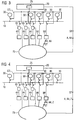
- FIG. 2 is an embodiment for operating the arrangement according to FIG. 1 or for the operation of the energy supply network 10, in which the energy distribution device 20 changes and adjusts its energy supply conditions as a function of the respective time-dependent detected load dynamics and transmits the respective energy supply conditions to the energy consumption devices by means of the communication device 70.
- the energy supply conditions of the energy distribution device 20 are identified by the reference symbol L.
- the energy supply conditions are transmitted by the energy distribution device 20 in the form of a delivery signal AL via the communication device 70, for example to the energy consumption device 50 '.
- the energy consumption device 50 ' is designed in such a way that it evaluates the received delivery signal AL or the energy supply conditions L contained therein and compares it with its individually stored energy acceptance conditions. If the energy supply conditions L and the energy consumption conditions of the energy consumption device 50 'match, then the energy consumption device 50' will switch on and decrease the energy offered by the energy distribution device 20. Otherwise, if the delivery conditions L of the energy distribution device 20 deviate from the energy acceptance conditions of the energy consumption device 50 ', the energy consumption device 50' will switch off and reject the acceptance of the energy offered.
- the individual energy acceptance conditions of the energy consumption device 50 ' are predetermined, for example, on the end customer side, that is to say by the owner or operator of the energy consumption device 50', and input into the energy consumption device 50 '.
- Such an input of the energy acceptance conditions may for example take place via a PC, if the energy consumption device has a corresponding interface, or by a corresponding input device on the energy consumption device 50 '.
- the energy distribution device 20 determines that the dynamic network load or load dynamics of the energy supply network is too great and the energy decrease should be slowed down, it will change the delivery conditions accordingly to make the energy consumption by the energy consumption device 50 'less attractive do. For example, the energy distribution device 20 will indicate in the energy supply conditions that the energy quality can no longer be ensured to the extent hitherto or that the origin of the energy can no longer be guaranteed. For example, the power distribution device 20 can notify the energy consuming device 50 'that instead of the otherwise provided environmentally friendly energy (eg solar energy or wind energy) only nuclear power can be provided. Also, the Energyverteil coupled 20 can significantly increase the selling price of the energy, so that for the energy consumption device 50 ', an energy decrease is too expensive and therefore they "voluntarily” dispensed with an energy loss.
- the energy distribution device 20 can notify the energy consuming device 50 'that instead of the otherwise provided environmentally friendly energy (eg solar energy or wind energy) only nuclear power can be provided.
- the Energyverteil worn 20 can significantly increase the selling price of the energy
- the power consumption device 50 has given the control authority to the power distribution device 20: this means that switching on and off of the power consumption device 50' exclusively by the power distribution device 20 is taken over.
- the energy consumption device 50 'transmits its desired energy acceptance conditions A in the form of a corresponding signal AA via the communication device 70 to the energy distribution device 20.
- the energy distribution device 20 compares the receiving energy acceptance conditions A of the energy consumption device 50' with their respective delivery conditions L and switches the energy consumption device 50 'with a Control signal ST when the energy supply conditions L agree with the energy acceptance conditions A and turns off the energy consumption device 50 'with the control signal ST, if delivery conditions and acceptance conditions do not correlate.
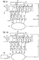
- the energy consumption device 50 indicates not only their respective energy acceptance conditions, but also a period of time or a time limit within which or up to which an energy delivery by the energy distribution device 20 or by the energy supply network 10 is to take place.
- the corresponding indication Z is transmitted by the energy consumption device 50 'via the communication device 70 to the energy distribution device 20.
- the energy distribution device 20 will also take into account the corresponding time period or time limit when the energy consumption device 50 'is switched on and off, even if the energy acceptance conditions of the energy consumption device 50 do not match the energy supply conditions L of the energy distribution device 20, but preferably only then if the deviations are within a predetermined or admissible frame, which is predetermined in advance on the end customer side or is likewise transmitted to the energy distribution device 20 by the energy consumption device 50 '.
- FIG. 5 is another embodiment of the operation of the arrangement according to FIG. 1 shown.
- the energy-consuming device 50 ' is designed in such a way that, in addition to its energy acceptance conditions A, it also transmits a device type specification P or a parameter set P corresponding to the device type specification to the energy distribution device 20 via the communication device 70.
- the device type specification or the parameter set P indicates, for example, which type of energy consumption device is actually involved.
- the energy consuming device 50 ' may communicate that it is a refrigerator or a freezer, or the like, and what the performance curves of the device look like.
- the energy distribution device 20 is even better able to reduce the dynamic network load or load dynamics in the energy supply network 10, namely by selectively targeting the energy consumption device 50' then turns on when the network load in the power grid 10 for the respective type of device is sufficiently low.
- the device type specification makes it possible to use the energy consumption device 50 'as a kind of energy buffer or storage. For example, if the energy consumption device 50' is a freezer, the energy distribution device 20 can, at a predicted load increase, already before this load increase occurs Turn on 50 'to cool the cooling device, so that after the load has entered the cooling device 50' can be turned off again. As a result, a relatively uniform utilization of the power supply network 10 is ensured.
- the energy consumption device 40 ' is, for example, a power consumption device that is itself unable to the communication device 70 and the power distribution device 20 to communicate. For this reason, the energy consumption device 40 'is connected via the ballast 60 both to the power supply network 10 and to the communication device 70.
- the control of the energy consumption device 40 'thus takes place via the ballast 60.
- the ballast 60 can receive, for example, delivery conditions L of the energy distribution device 20 and compare with stored in the ballast 60 energy acceptance conditions. If the energy acceptance conditions match the energy delivery conditions, the ballast 60 will turn on and off the energy consuming device 40 '.
- the ballast 60 transmits the energy acceptance conditions A of the energy consuming device 40 'to the energy distributing device 20 via the communication device 70. Control over both the ballast 60 and the energy consuming device 40' is provided to the energy distributing device 20. It compares its energy supply conditions L with the energy consuming conditions A of FIG Energy consumption device 40 'and turns on the energy consumption device 40' via the ballast 60 with the control signal ST, if delivery conditions and acceptance conditions correspond; if these do not agree, the energy consumption device 40 'is switched off by the energy distribution device 20 with the control signal ST.
- the ballast 60 transmits a device type specification P or a parameter set P describing the energy consumption device 40 'to the energy distribution device 20 so that it knows the electrical behavior of the energy consumption device 40'. This allows the power distribution device 20 to turn on and off the power consuming device 40 'at appropriate times Network load fluctuations in the power grid 10 to keep in acceptable ranges.
- ballast 60 In connection with the FIG. 9 An operating mode of the ballast 60 will now be explained by way of example in which, in addition to the energy acceptance conditions A and the device type specification P, this also indicates a time span or a time limit Z within which or up to which an energy delivery by the energy distribution device 20 is to take place.
- the energy distribution device 20 thus has to take into account a further parameter when it controls the energy consumption device 40 '.
- FIG. 10 is a further embodiment of an arrangement with a power grid 10, a power distribution device 20, an energy generating device 30 and energy consumption devices 40, 40 ', 50 and 50' shown.
- a management device in the form of a trading system is additionally provided, which in the FIG. 10 designated by the reference numeral 100.
- the task of the management device 100 is to store the energy supply conditions of the energy distribution device 20 connected to the energy supply network 10.
- the energy consumption devices 50 and 50 'and the ballasts 60 can access the management device 100 and the data stored therein via the communication device 70 and select tariff options according to which they want to obtain energy from the energy supply network 10.
- the corresponding information can be used by the energy consumption devices 50, 50 'and the ballasts 60 to generate energy acceptance conditions A in order to transmit them to the management device 100 or directly to the energy distribution device 20 for the purpose of energy absorption.
- FIG. 11 is an embodiment of a ballast 60 for the arrangements according to the FIGS. 1 to 10 shown.
- a communication interface 200 for communication with an energy distribution device connected to a communication device 70 and / or for communication with a management device.
- the ballast 60 can receive energy supply conditions L and control signals ST of the energy distribution device 20 and send its own energy acceptance conditions A, device type information G or device parameters P and time specifications Z to the communication device 70.
- an input device 210 for the consumer-side input of energy acceptance conditions A, device type information G and timing Z exists.
- a control device 220 Connected to the communication interface 200 and the input device 210 is a control device 220 which, for example, has a computer system 221 and a memory 222 and can compare the consumer-side energy acceptance conditions A, for example, with energy supply conditions L received from the energy distribution device or the management device.
- a switch 230 connected to the control device 220 has a switch connection 230a with which the switch can be electrically connected to a power consumption device 40, 40 '. With a switch connection 230b, the switch 230 can be electrically connected to the energy supply network 10.
- the switch 230 is turned on by the controller 220 when the consumer-side power take-off conditions A correspond to the received power supply conditions L and turned off by the controller 220 when the consumer-side Energy acceptance conditions A deviate from the received energy supply conditions L.
- the switch 230 is turned on by the controller 220 when a corresponding control signal ST is received from the power distribution device.
Landscapes
- Engineering & Computer Science (AREA)
- Power Engineering (AREA)
- Management, Administration, Business Operations System, And Electronic Commerce (AREA)
Description
Die Erfindung bezieht sich auf ein Verfahren zum Betreiben einer Anordnung mit zumindest einer Energieverteileinrichtung, einer Mehrzahl an Energieverbrauchseinrichtungen und einem Energieversorgungsnetz, an das die zumindest eine Energieverteileinrichtung und die Mehrzahl an Energieverbrauchseinrichtungen angeschlossen sind.The invention relates to a method for operating an arrangement with at least one energy distribution device, a plurality of energy consumption devices and a power supply network to which the at least one energy distribution device and the plurality of energy consumption devices are connected.
Strom ist bekanntermaßen nur in sehr begrenztem Umfang speicherbar. Dieser Umstand führt dazu, dass erzeugte Energie stets auch irgendwo abgenommen werden muss. Die Einbeziehung von alternativen und wetterabhängigen Energien sowie die absolut unkoordinierte Abnahme durch die Endverbraucher führen bei derzeitigen Energieverteilsystemen zu einer sehr hohen Lastdynamik.Electricity is known to be storable only to a very limited extent. This circumstance means that the generated energy always has to be taken off somewhere. The inclusion of alternative and weather-dependent energies as well as the absolutely uncoordinated acceptance by the end users lead to a very high load dynamics in current energy distribution systems.
Zwischen Energieerzeuger und Endverbraucher gibt es derzeit keine direkte Kopplung zur Regelung und Optimierung des Lastflusses. Dies führt beispielsweise dazu, dass überschüssige Energie, die z.B. durch Windkraftanlagen in Schwachlastzeiten erzeugt wird, nicht kostenoptimiert bzw. umweltschonend genutzt werden kann.There is currently no direct coupling between power generator and end user to control and optimize the load flow. For example, this results in excess energy, e.g. produced by wind turbines during off-peak hours, can not be used cost-optimized or environmentally friendly.
Auch wirtschaftlich nachteilig ist diese hohe Lastdynamik, da ungeplante Lastflussverschiebungen im Netzverbund zu Vertragsstrafen führen können, wenn vorab vereinbarte Energieleistungen nicht abgenommen werden können. Diese Situation verschärft sich mit zunehmender Installation von alternativen Energieerzeugungsanlagen, wie zum Beispiel durch Windparks, Blockheizkraftwerke, dezentrale Energieerzeuger etc., da diese keine konstante Energiebereitstellung gewährleisten können. Die dadurch im Mittel noch höhere Dynamik zwischen Spitzenlast- und Schwachlastbetrieb als bisher stellt noch höhere technische Anforderungen an die von Energieversorgern oder Netzbetreibern betriebenen Energieverteileinrichtungen, mit denen Energieversorgungsnetze betrieben werden.Also economically disadvantageous is this high load dynamics, since unplanned load flow shifts in the network can lead to contractual penalties, if pre-agreed energy achievements can not be taken off. This situation is exacerbated by the increasing installation of alternative energy generation systems, such as wind farms, combined heat and power plants, decentralized energy producers, etc., as these can not guarantee a constant supply of energy. The on average even higher dynamics between peak load and low load operation than before places even higher technical demands on those of energy suppliers or network operators powered power distribution equipment with which power grids are operated.
Aus der Druckschrift
Der Erfindung liegt die Aufgabe zugrunde, ein Verfahren zum Betreiben einer Anordnung mit zumindest einer Energieverteileinrichtung anzugeben, bei dem im Energieversorgungsnetz im Mittel eine geringere Lastdynamik bzw. weniger Lastschwankungen als bisher erreicht werden.The invention has for its object to provide a method for operating an arrangement with at least one energy distribution device, in which in the energy supply network on average a lower load dynamics or less load fluctuations than previously achieved.
Diese Aufgabe wird erfindungsgemäß durch ein Verfahren mit den Merkmalen gemäß Patentanspruch 1 gelöst. Vorteilhafte Ausgestaltungen des erfindungsgemäßen Verfahrens sind in Unteransprüchen angegeben.This object is achieved by a method having the features according to claim 1. Advantageous embodiments of the method according to the invention are specified in subclaims.
Danach ist erfindungsgemäß vorgesehen, dass die Energieverbrauchseinrichtungen und die Energieverteileinrichtung über eine Kommunikationseinrichtung in Verbindung stehen und die Energieverteileinrichtung Energielieferbedingungen in Abhängigkeit von der jeweiligen Netzlast oder Netzlastschwankungen bzw. Lastdynamik des Energieversorgungsnetzes zeitabhängig ermittelt bzw. festlegt und dass den Energieverbrauchseinrichtungen gemäß deren individuell abgespeicherten Energieabnahmebedingungen individuell Energie bereitgestellt wird oder nicht. Eine zeitabhängige Ermittlung der (dynamischen) Netzlast bzw. von Lastschwankungen kann beispielsweise durch ein zeitlich kontinuierliches, regelmäßiges (in regelmäßigen Zeitabständen), unregelmäßiges, beispielsweise stochastisch verteiltes, Messen der Netzlast erfolgen.According to the invention, it is provided that the energy consumption devices and the energy distribution device are connected via a communication device and the energy distribution device determines or determines energy supply conditions as a function of the respective network load or network load fluctuations or load dynamics of the energy supply network, and individually allocates energy to the energy consumption devices according to their individually stored energy acceptance conditions is provided or not. A time-dependent determination of the (dynamic) network load or of load fluctuations can be carried out, for example, by measuring the network load at regular, regular intervals (at regular intervals), irregular, for example stochastically distributed.
Ein wesentlicher Vorteil des erfindungsgemäßen Verfahrens besteht darin, dass die Energieverteileinrichtung erfindungsgemäß in die Lage versetzt wird, auf die Lastdynamik selbst Einfluss zu nehmen, indem sie die jeweilige Netzlast des Energieversorgungsnetzes zeitabhängig ermittelt und in Abhängigkeit von der jeweiligen Netzlast bzw. von festgestellten oder zu erwartenden Netzlastschwankungen Energielieferbedingungen individuell festlegt. Konkret hat die Energieverteileinrichtung somit die Möglichkeit, bei einem Energieüberangebot über eine Anpassung der Energielieferbedingungen die Energieabgabe für die Energieverbraucher attraktiver zu machen und bei absehbarem oder bereits aufgetretenem Energiemangel eine Energielieferung für die Energieverbraucher zu erschweren bzw. unattraktiver zu machen.A significant advantage of the method according to the invention is that the energy distribution device according to the invention is enabled, on the load dynamics themselves To influence by determining the respective network load of the power grid time-dependent and individually determines energy supply conditions depending on the respective network load or determined or anticipated network load fluctuations. In concrete terms, the energy distribution device thus has the possibility of an excess of energy make the energy taxation more attractive for energy consumers by adapting the energy supply conditions and, in the event of a foreseeable or already occurring lack of energy, make it more difficult or unattractive for energy consumers to supply energy.
Die Energielieferbedingungen können eine Vielzahl an Parametern vorsehen: Beispielsweise können die Energielieferbedingungen festlegen, welche Mindestqualität die Energie erreicht, beispielsweise - im Falle elektrischer Energie -
- welche Mindestfrequenzstabilität überschritten wird und
- welche maximale Spannungsschwankung, welches maximale Maß an Oberwellen oder welcher maximale Ausstoß an Kohlendioxid (CO2) pro Kilowattstunde unterschritten wird.
- which minimum frequency stability is exceeded and
- which maximum voltage fluctuation, which maximum level of harmonics or which maximum emission of carbon dioxide (CO2) per kilowatt hour is exceeded.
Alternativ oder zusätzlich können die Energielieferbedingungen auch einen Preis oder Preisindikator enthalten, der die von der Energieverteileinrichtung verlangte Vergütung pro Leistungseinheit (z. B. kWh) definiert. Auch können die Energielieferbedingungen festlegen, dass die Energie auf eine bestimmte Art und Weise (z. B. Atomkraft, Verbrennen fossiler Brennstoffe, erneuerbare Energiequellen (Windenergie, Solarenergie, Wasserkraft)) erzeugt wird oder auf bestimmte Art und Weise gerade nicht erzeugt wird.Alternatively or additionally, the energy delivery conditions may also include a price or price indicator that defines the remuneration required by the energy distribution device per unit of power (eg, kWh). Also, the energy delivery conditions may dictate that the energy be generated in a particular manner (eg, nuclear power, fossil fuel burning, renewable energy sources (wind, solar, hydropower)) or in some way not being generated.
Die Betreiber der Energieverteileinrichtungen, also die Energienetzbetreiber bzw. die Energieversorgungsunternehmen, erhalten durch die beschriebene dynamische Anpassung der Energielieferbedingungen somit einen mittelbaren Einfluss auf das Verhalten der Verbraucher und können somit den Lastfluss automatisch selbst optimieren und damit die Energieverteilung quasi "in Echtzeit" stabilisieren. Daraus ergeben sich für die Netzbetreiber bzw. Energieversorgungsunternehmen deutliche Kostenvorteile, denn Netzüberlastungen und dadurch bedingte Abschaltungen können vermieden werden; dies führt zu höherer Versorgungssicherheit und höherer Energiequalität.The operators of the energy distribution facilities, ie the energy network operators or the energy supply companies, obtained by the described dynamic adjustment of the energy supply conditions thus an indirect influence on the behavior of consumers and thus can automatically optimize the load flow itself and thus stabilize the energy distribution quasi "in real time". This results in considerable cost advantages for network operators and energy supply companies, as network congestion and the resulting shutdowns can be avoided; this leads to higher security of supply and higher energy quality.
Gemäß der Erfindung ist vorgesehen, dass die Energieverteileinrichtung ein ihre jeweiligen Energielieferbedingungen angebendes Abgabesignal erzeugt und dieses über die Kommunikationseinrichtung an die Energieverbrauchseinrichtungen sendet und dass zumindest eine der Energieverbrauchseinrichtungen individuell prüft, ob die mit dem Abgabesignal empfangenen Energielieferbedingungen mit ihren individuell abgespeicherten Energieabnahmebedingungen übereinstimmen, und im Falle einer Übereinstimmung zwischen Energielieferbedingungen und Energieabnahmebedingungen die angebotene Energie zu den empfangenen Energielieferbedingungen abnimmt und andernfalls ablehnt. Bei dieser Variante erfolgt die Steuerung der Energieabnahme also verbraucherseitig, so dass der Endkunde nichts über sein eigenes Verhalten nach außen preisgeben muss, denn die Informationen fließen nur vom Energieversorger zum Endkunden und nicht umgekehrt.According to the invention, it is provided that the energy distribution device generates a delivery signal indicating its respective energy supply conditions and transmits this via the communication device to the energy consumption devices and that at least one of the energy consumption devices individually checks whether the energy supply conditions received with the delivery signal coincide with their individually stored energy acceptance conditions, and If there is a match between energy supply conditions and energy acceptance conditions, the offered energy decreases to the received energy supply conditions and otherwise refuses. In this variant, the control of the energy consumption therefore takes place on the consumer side, so that the end customer does not have to disclose anything about his own behavior to the outside, because the information flows only from the energy supplier to the end customer and not vice versa.
Gemäß einer anderen bevorzugten Ausgestaltung des Verfahrens ist vorgesehen, dass zumindest eine der Energieverbrauchseinrichtungen ihre individuell abgespeicherten Energieabnahmebedingungen an die Energieverteileinrichtung über die Kommunikationseinrichtung übermittelt und die Energieverteileinrichtung die Energieabnahme dieser Energieverbrauchseinrichtung anschließend durch ein individuelles Steuersignal steuert. Bei dieser Ausgestaltung des Verfahrens erfolgt die Steuerung der Energieabnahme also seitens der Energieverteileinrichtung.According to another preferred embodiment of the method, it is provided that at least one of the energy consumption devices transmits their individually stored energy acceptance conditions to the energy distribution device via the communication device and the energy distribution device then controls the energy decrease of this energy consumption device by means of an individual control signal. In this embodiment of the method, the control of the energy consumption therefore takes place on the part of the energy distribution device.
Die beiden oben beschriebenen Varianten können auch miteinander kombiniert werden, indem beispielsweise einige Verbraucher selbst steuern und andere Verbraucher seitens der Energieverteileinrichtung gesteuert werden.The two variants described above can also be combined with one another, for example by controlling some consumers themselves and controlling other consumers on the part of the energy distribution device.
Auch kann im Rahmen einer weiteren bevorzugten Ausgestaltung des Verfahrens vorgesehen werden, dass eine an die Kommunikationseinrichtung angeschlossene Verwaltungseinrichtung die Energieabnahmebedingungen der Energieverteileinrichtung speichert und dass die Energieverbrauchseinrichtungen jeweils die in der Verwaltungseinrichtung abgespeicherten Energielieferbedingungen mit ihren individuell abgespeicherten Energieabnahmebedingungen vergleichen und im Falle einer Übereinstimmung die Energie von dem Energieversorgungsnetz abnehmen und andernfalls ablehnen. Bei dieser Variante erfolgt die Kommunikation zwischen der Energieverteileinrichtung und den Energieverbrauchseinrichtungen nur mittelbar unter Einschaltung der Verwaltungseinrichtung, die das "Aushandeln" zwischen Energieabnahmebedingungen und Energielieferbedingungen ermöglicht.It can also be provided within the scope of a further preferred embodiment of the method that an administration device connected to the communication device stores the energy acceptance conditions of the energy distribution device and that the energy consumption devices each have the Compare in the management facility stored energy supply conditions with their individually stored energy acceptance conditions and in the case of a match the power from the power grid and otherwise decline. In this variant, the communication between the energy distribution device and the energy consumption devices takes place only indirectly with the involvement of the administrative device, which enables the "negotiation" between energy acceptance conditions and energy supply conditions.
Im Übrigen kann eine solche Verwaltungseinrichtung ein energieanbieterübergreifendes Tradingsystem oder Handelssystem bilden. Energieverteileinrichtungen, Energieverbrauchseinrichtungen und Energieerzeugungseinrichtungen können mit diesem über ein beispielsweise standardisiertes Kommunikationsnetzwerk verbunden werden, z.B. das Internet. Die Energieverbraucher können über das Tradingsystem bestimmte Energiemengen mit Angabe einer Preisgrenze kaufen oder einfach bei Bedarf (on demand) das preiswerteste Energieangebot vom preiswertesten Energieerzeuger nutzen bzw. kaufen. Den Energieverbrauchern kann beispielsweise über eine tabellarische Auflistung unter Angabe von Preisen und weiteren Kriterien (z.B. Herstellungsart Windkraft, Wasserkraft, Atomkraft etc.) eine Auswahlmöglichkeit angeboten werden.Incidentally, such a management device can form an energy supplier-spanning trading system or trading system. Power distribution devices, energy consumption devices and power generation devices may be connected to it via, for example, a standardized communication network, e.g. the Internet. The energy consumers can use the trading system to buy certain amounts of energy with a price limit or simply use (on demand) the cheapest energy supply from the cheapest energy producer or buy. The energy consumers can, for example, be offered a choice by means of a tabular list stating prices and other criteria (for example, the production method wind power, hydropower, nuclear power, etc.).
Entsprechend können die Energieverteileinrichtungen bestimmte Energiemengen anbieten, wenn ein attraktives Preisniveau oder ansonsten attraktive Energieabnahmebedingungen erreicht worden sind oder wenn ausreichende Energieanforderungen vorliegen. Damit die Nutzer bzw. Teilnehmer des Systems proaktiv über die jeweils gültigen Preise informiert werden, kann ein event-orientiertes System eingesetzt werden, das die Preisinformation bzw. die Energieabnahmebedingungen im Netzwerk durch IP Multicasting, Application Layer Multicasting (z.B. HMTP, NICE und NARADA), WebService Mechanismen (wie WS Eventing oder WS Notification) oder Power-Line Netzwerktechnologie verbreitet.Accordingly, the power distribution facilities may offer certain amounts of energy when an attractive price level or otherwise attractive energy acceptance conditions have been achieved or when sufficient energy requirements exist. In order to proactively inform the users or subscribers of the current prices, an event-oriented system can be used which multicasts the price information or the energy acceptance conditions via IP multicasting, application layer multicasting (eg HMTP, NICE and NARADA). , WebService mechanisms (such as WS Eventing or WS Notification) or Power-Line network technology.
Durch die dynamische Anpassung der Energielieferbedingungen seitens der Energieverteileinrichtung, insbesondere durch eine dynamische Anpassung der Preispolitik, wird der Endverbraucher abhängig von der jeweiligen Netzlastsituation zu einem netzlastoptimierten Verbrauch motiviert. Der Endverbraucher hat damit beispielsweise die Möglichkeit, Geräte und Anlagen mit hohem Energieverbrauch abhängig vom aktuellen Preisniveau ein- bzw. auszuschalten. Das beschriebene Trading- bzw. Verwaltungssystem ist damit ein stabilisierendes Element für die Energieversorgungsnetze.Due to the dynamic adaptation of the energy supply conditions by the energy distribution device, in particular by a dynamic adjustment of the price policy, the end user is motivated depending on the respective network load situation to a network load optimized consumption. For example, the end user has the option of switching devices and systems with high energy consumption on or off depending on the current price level. The trading or administrative system described is thus a stabilizing element for the energy supply networks.
Dezentrale Energieerzeuger, wie beispielsweise Haushalte mit Solarenergieanlagen, können mit diesem System auch bestimmte Energiemengen im Netzwerk anbieten, wenn sie diese aufgrund von Abwesenheit (z.B. Urlaub) nicht selbst nutzen können. Auch kann der Energiebedarf für bestimmte Herstellungsarten über das Tradingsystem erfasst werden; dies dient der Preisfindung und Preisdifferenzierung zwischen den einzelnen Erzeugungsarten. Energieartspezifische Investitionen können davon abgeleitet werden. Insgesamt wird ein Beitrag zum Umweltschutz geleistet, weil sich Energieverbrauch und Energiebereitstellung gemeinsam miteinander optimieren lassen.Decentralized energy producers, such as households with solar energy systems, can also use this system to provide certain amounts of energy in the network if they are unable to use them themselves due to their absence (eg holidays). Also, the energy requirements for certain types of production can be recorded via the trading system; This serves to determine prices and price differentiation between the individual types of production. Energy specific investments can be derived from this. Overall, a contribution to environmental protection is made because energy consumption and the provision of energy can be optimized together.
Die Energieverbrauchseinrichtungen - nachfolgend auch nur kurz Endgeräte oder Geräte genannt - können beispielsweise mit einem Vorschaltgerät ausgestattet werden, das über die Kommunikationseinrichtung die Preisspanne für einen definierten Zeitraum erhält; der Endkunde kann in diesem Falle einen kostenoptimierten Energiebezug sicherstellen, indem er beispielsweise seine Endgeräte auf ein für ihn akzeptables Preisniveau einstellt. Das Vorschaltgerät zeigt vorzugsweise die aktuelle Preisspanne in einer geeigneten Form an.The energy consumption devices - hereinafter referred to as terminals or devices for short - can be equipped, for example, with a ballast which receives the price range for a defined period of time via the communication device; In this case, the end customer can ensure cost-optimized energy procurement by, for example, adjusting his terminals to an acceptable price level. The ballast preferably displays the current price range in a suitable form.
Die Netzbetreiber bzw. Energieversorger können mit den Energieverteileinrichtungen ihrerseits ihre Energieeinkaufspreise, für die sie Energie beziehen wollen, vorgeben, beispielsweise in Form einer Preisspanne. Der Netzbetreiber bzw.The network operators or energy suppliers can use the energy distribution devices in turn to set their energy purchase prices, for which they want to obtain energy, for example in the form of a price range. The network operator or
Energieversorger hat damit ein weiteres Instrumentarium zur Lastflusssteuerung.Energy supplier thus has another instrument for load flow control.
Zur Kommunikation zwischen den Energieverteileinrichtungen und den Energieverbrauchseinrichtungen wird bevorzugt parallel zum Stromnetz ein Kommunikationsnetz (z. B. WLAN, DSL, UMTS, etc.) zur Verfügung gestellt, mit dem beispielsweise eine Preisspanne übertragen wird und an das beispielsweise fernauslesbare Energiezähler zur Abfrage des endkundenseitigen Energieverbrauches pro Preisintervall angeschlossen werden können.For communication between the energy distribution devices and the energy consumption devices, a communication network (eg WLAN, DSL, UMTS, etc.) is preferably provided in parallel with the power network, with which, for example, a price range is transmitted and to the, for example, remotely readable energy meter for querying the end customer Energy consumption per price interval can be connected.
Alternativ kann das Energienetz auch selbst zur Kommunikation genutzt werden und so die aktuellen Preise selbst übertragen, beispielsweise analog zu Vorwahlgeräten bei Telefonen, die automatisch die billigste Vorwahl nutzen und sich automatisch aktualisieren. Ein Vorteil der Nutzung des Stromnetzes bestünde darin, dass die Informationen ohne zusätzliche Verkabelung am notwendigen Ort verfügbar wären.Alternatively, the energy network itself can be used for communication and thus transfer the current prices themselves, for example analogous to dialers in phones that automatically use the cheapest area code and automatically update. An advantage of using the power grid would be that the information would be available at the necessary location without additional cabling.
Auch kann vorgesehen werden, dass endkunden- bzw. verbraucherseitig nicht nur ein Tarif ausgewählt wird, sondern auch eine zeitliche "Schmerzgrenze" bzw. ein spätester Liefertermin, bis zu dem eine Energielieferung erfolgen soll. Eine solche Verfahrensvariante wäre typischerweise einsetzbar für Geschirrspüler und Waschmaschinen, Nachtspeicheröfen (als Flexibilisierung des bisherigen "Nachttarifs"), Boiler, usw.It can also be provided that end customer or consumer side not only a tariff is selected, but also a temporal "pain threshold" or a late delivery date, to which an energy delivery is to take place. Such a process variant would typically be used for dishwashers and washing machines, night storage ovens (as a flexibilization of the previous "night tariff"), boilers, etc.
Auch kann für jedes Endgerät individuell eine lokale, zentrale oder dezentrale Policy-Verwaltung vorgesehen werden, womit jeweils auch statistisch tragfähige Nachfragemodelle realisiert werden können, beispielsweise in Kombination mit Spannungshöhe, Frequenz und Phasenansteuerung/-beschneidung.Also, a local, centralized or decentralized policy management can be provided individually for each terminal, whereby each statistically viable demand models can be realized, for example in combination with voltage level, frequency and phase control / circumcision.
Auch wird es als vorteilhaft angesehen, wenn die Anpassung der Energielieferbedingungen bzw. der Preispolitik mit der Erzeugung der Energie gekoppelt wird. Durch den Trend der Miniaturisierung wird es in Zukunft möglich sein, verschiedene Arten von "Energiespeichern" durch Privatleute im eigenen Heim betreiben zu lassen (z. B. Schwungräder, Wasserspeicher auf dem Dachboden (oder Fabrikhalle, Hochhaus, ...), Wärmespeicher, Wasserstofferzeugung, Brennstoffzellen, Akkus usw. Durch eine entsprechende Steuerung, beispielsweise durch eine entsprechende Preispolitik, können "Kleinerzeuger" motiviert werden, Kleinstanlagen bei sich zu installieren und zu günstigen Preisen Strom zu entnehmen, diesen "zwischenzuspeichern" und bei Spitzenbedarf wieder abzugeben. Der "Kleinerzeuger" kann nach Angebot und Nachfrage eigenverantwortlich entscheiden. Ein vorteilhafter Aspekt dieser letztgenannten Verfahrensvariante besteht dabei darin, dass die bisher bekannte zentrale Organisation der Energiezwischenspeicherung mit Großanlagen (z. B. in Form von Pumpspeicherwerken) dezentralisiert wird und für jeden zugänglich gemacht wird. Die Regelung kann automatisiert erfolgen, wobei Angebot und Nachfrage nur über den Preis bzw. sonstige Parameter, wie eingangs beschrieben, geregelt wird. D.h. wenn Energie gebraucht wird, muss der Preis nur solange gesteigert werden, bis die Kleinsterzeuger ihre Energie zur Verfügung stellen; es wird also im Idealfall nur noch eine einzige Stellschraube benötigt. Die Vorteile dieser Vorgehensweise lauten stichpunktartig:
- Dezentrale Zwischenspeicher werden im freien Markt verfügbar.
- Privatinvestitionen ermöglichen kostengünstige Zwischenspeicherung.
- Eigendynamik wird durch Angebot und Nachfrage gesteigert.
- Der Aufwand für die Strombereitstellung wird bei dem Netzbetreiber reduziert, da die Strombereitstellung teilweise ausgelagert wird.
- Eine zentrale Kontrolle und Überwachung bleibt dennoch einfach realisierbar.
- Decentralized buffers become available in the open market.
- Private investment enables cost-effective caching.
- Momentum is increased by supply and demand.
- The effort for the provision of electricity is reduced at the grid operator, since the power supply is partially outsourced.
- Nevertheless, central control and monitoring remain easy to implement.
Die Verfügbarkeit der Energie leidet unter dem beschriebenen Modell erfreulicherweise nicht, da durch die Preispolitik auch ein hoher Anreiz zum Zwischenpuffern der Energie geschaffen werden kann. Wenn nämlich der Preisunterschied zwischen dem Strom, den man z.B. in der Nacht zum "Puffern" erhalten kann, und dem Strom, den man um 12:00 Mittags wieder verkaufen kann, sehr groß wird, werden sich in jedem Fall Anbieter zur Zwischenspeicherung finden. In der Praxis wird sich zeigen, dass die hier beschriebenen dezentralen Systeme aus diesem Grund besser funktionieren werden als die bisher bekannten zentralen Versorgungssysteme.Fortunately, the availability of energy does not suffer from the described model, since the pricing policy can also create a high incentive to buffer the energy. Namely, if the price difference between For example, the electricity that you can get to "buffer" during the night, and the electricity that you can resell at 12:00 noon, will be very large. In any case, you will find caching providers. In practice, it will become apparent that the decentralized systems described here will work better for this reason than the previously known centralized supply systems.
Erreicht wird also eine typische Win-Win-Situation, denn der Endverbraucher reduziert Stromkosten und der Netzbetreiber optimiert seine Ressourcen. Der Netzbetreiber kann in einer Spitzenlastsituation die Endverbraucher durch Änderung der Lieferbedingungen herunterregeln und die damit gewonnene Energiereserve zum Höchstpreis im Europäischen Netzverbund verkaufen. Die Netzbetreiber haben insbesondere über die Preisvorgabe direkten Einfluss auf den Energieverbrauch der Endkunden und können somit den Lastfluss optimieren und damit die Energieverteilung stabilisieren. Daraus ergeben sich für den Netzbetreiber erhebliche Kostenvorteile, da Überlastungen und dadurch bedingte Abschaltungen vermieden werden können; dies führt zu höherer Versorgungssicherheit und höherer Energiequalität.Thus, a typical win-win situation is achieved because the end user reduces electricity costs and the network operator optimizes his resources. In a peak-load situation, the grid operator can down-regulate end users by changing the delivery conditions and sell the resulting energy reserve at the highest price in the European grid network. In particular, the network operators have a direct influence on the energy consumption of end customers through the price specification and can therefore optimize the load flow and thus stabilize the energy distribution. This results in significant cost advantages for the network operator, since congestion and consequent shutdowns can be avoided; this leads to higher security of supply and higher energy quality.
Auch können Wettbewerbsvorteile für Endgerätehersteller ermöglicht werden, da Endgerätehersteller als Trendsetter und Innovationsführer auftreten können, z. B. können Waschmaschinen mit integrierter Steuereinrichtung für eine intelligente Stromabschaltung angeboten werden und als umwelt- und ressourcenschonend deklariert werden. Insgesamt wird eine Entlastung der Umwelt durch eine effizientere Nutzung vorhandener Ressourcen als bisher erreicht.Also, competitive advantages for terminal manufacturers can be made possible as terminal manufacturers can act as trendsetters and innovation leaders, e.g. B. washing machines can be offered with integrated control device for an intelligent power cut and declared to be environmentally and resource efficient. Overall, a relief of the environment by a more efficient use of existing resources than previously achieved.
Über die beschriebene Kommunikationseinrichtung kann im Übrigen auch ein Authentifizierungssystem eingerichtet werden, das nur berechtigten Anwendern eine Teilnahme erlaubt, also beispielsweise solchen, die einen entsprechenden Serviceoder Wartungsvertrag abgeschlossen haben.By the way, an authentication system can also be set up via the described communication device, which only allows authorized users to participate, that is, for example, those who have concluded a corresponding service or maintenance contract.
Als Erfindung wird außerdem ein Vorschaltgerät zum Anschließen einer Energieverbrauchseinrichtung an ein Energieversorgungsnetz angesehen, welches die Merkmale des Anspruchs 5 aufweist.As an invention, a ballast for connecting a power consumption device is also considered to a power grid, which has the features of claim 5.
Erfindungsgemäß ist das Vorschaltgerät ausgestattet mit einer Kommunikationsschnittstelle zur Kommunikation mit einer Energieverteileinrichtung oder zur Kommunikation mit einer Verwaltungseinrichtung, die Energielieferbedingungen der an das Energieversorgungsnetz angeschlossenen Energieverteileinrichtungen speichert, einer Eingabeeinrichtung zur verbraucherseitigen Eingabe von Energieabnahmebedingungen, einer Steuereinrichtung, die die verbraucherseitigen Energieabnahmebedingungen mit von der Energieverteileinrichtung oder der Verwaltungseinrichtung empfangenen Energielieferbedingungen vergleicht, und einem mit der Steuereinrichtung verbundenen Schalter, der elektrisch zwischen die Energieverbrauchseinrichtung und das Energieversorgungsnetz schaltbar ist und der von der Steuereinrichtung einschaltbar ist, wenn die verbraucherseitigen Energieabnahmebedingungen den empfangenen Energielieferbedingungen entsprechen, und der von der Steuereinrichtung ausschaltbar ist, wenn die verbraucherseitigen Energieabnahmebedingungen von den empfangenen Energielieferbedingungen abweichen.According to the invention, the ballast is equipped with a communication interface for communication with an energy distribution device or for communication with an administrative device which stores energy supply conditions of the power distribution network connected to the energy distribution network, an input device for consumer-side input of energy acceptance conditions, a control device, the consumer-side energy collection conditions of the energy distribution device or compares the received energy supply conditions with the management device, and a switch connected to the control device, which is switchable electrically between the energy consuming device and the power supply network and which is switchable by the control device, if the consumer-side energy acceptance conditions correspond to the received energy supply conditions, and which can be switched off by the control device, if the consumption deviate from the received energy supply conditions.
Das vorschaltgerät ist in einen Betriebsmodus schaltbar, bei dem die Steuerungshoheit über den Schalter des Vorschaltgeräts der Energieverteileinrichtung derart übertragen ist, dass die Energieverteileinrichtung den Schalter selbsttätig ein- und ausschalten oder stufenlos regeln kann. Die letztgenannte Variante des stufenlosen Regelns ist insbesondere dann interessant, wenn eine Integration des Vorschaltgerätes in die Energieverbrauchseinrichtung und/oder eine datenmäßige Kopplung der Geräte erfolgt und das Vorschaltgerät so Wissen über das Laufzeitverhalten der Energieverbrauchseinrichtung mit in die Regelentscheidung einbeziehen kann (z.B. maximale Latenzzeiten für Arbeitsschritte, aktuelle Messwerte und deren Abweichung zu den Sollwerten etc.).The ballast is switchable to an operating mode in which the control sovereignty over the switch of the ballast of the power distribution device is transmitted such that the power distribution device can switch on and off automatically or steplessly regulate the switch. The latter variant of stepless control is particularly interesting if an integration of the ballast in the energy consumption device and / or a data coupling of the devices and the ballast so knowledge about the runtime behavior of energy consumption device can include in the control decision (eg maximum latencies for steps , current Measured values and their deviation from the nominal values, etc.).
Auch wird es als vorteilhaft angesehen, dass das Vorschaltgerät eine Betriebsart zur Verfügung stellt, in der das Vorschaltgerät den voraussichtlichen Energiebedarf der Energieverbrauchseinrichtung an die Energieverteileinrichtung übermittelt und abwartet, bis die Energieverteileinrichtung den Schalter selbsttätig ein- und ausschaltet. Vorzugsweise übermittelt das Vorschaltgerät auch eine Zeitspanne oder eine Zeitgrenze, innerhalb derer bzw. bis zu der die Energielieferung erfolgen soll.It is also considered advantageous that the ballast provides an operating mode in which the ballast transmits the expected energy requirement of the energy consumption device to the energy distribution device and waits until the energy distribution device automatically switches the switch on and off. The ballast preferably also transmits a time span or a time limit within which or up to which the energy supply should take place.
Bevorzugt ist das Vorschaltgerät geeignet, zumindest einen (internen) Messwert der Energieverbrauchseinrichtung und/oder zumindest eine Verbrauchskenngröße der Energieverbrauchseinrichtung zu ermitteln und diese an die Energieverteileinrichtung oder die Verwaltungseinrichtung weiterzuleiten. Beispielsweise kennzeichnet die Verbrauchskenngröße den Maximalverbrauch, die Verbrauchsdauer und/oder die Verbrauchshäufigkeit der Energieverbrauchseinrichtung. Im Falle einer Verfügbarkeit auch interner Messwerte der Energieverbrauchseinrichtung kann eine noch bessere Steuerung erfolgen, so dass letztlich der Benutzer der Energieverbrauchseinrichtung keinerlei Unterschied im Verhalten des Gerätes sieht (z. B. im Falle einer Kühltruhe), aber dabei trotzdem Energiekosten spart.The ballast is preferably suitable for determining at least one (internal) measured value of the energy consumption device and / or at least one consumption parameter of the energy consumption device and forwarding this to the energy distribution device or the management device. For example, the consumption parameter indicates the maximum consumption, the consumption duration and / or the consumption frequency of the energy consumption device. In the case of availability of internal measured values of the energy consumption device, even better control can take place, so that ultimately the user of the energy consumption device sees no difference in the behavior of the device (eg in the case of a freezer), but nevertheless saves energy costs.
Das Vorschaltgerät kann beispielsweise eine separate Komponente sein, die der Energieverbrauchseinrichtung endkundenseitig vorgeschaltet wird, alternativ kann das Vorschaltgerät auch baulich mit der zugeordneten Energieverbrauchseinrichtung verbunden oder in dieser integriert sein. Auch kann das Vorschaltgerät als eine Art intelligente Steckdose ausgeführt sein, die gebäudeseitig zur Verfügung gestellt wird.The ballast may for example be a separate component, which is the end of the energy consumption device upstream end customer, alternatively, the ballast can also be structurally connected to the associated energy consumption device or integrated in this. Also, the ballast can be designed as a kind of smart outlet, which is provided on the building side.
Durch den Gebrauch des beschriebenen Vorschaltgeräts bekommt der Endverbraucher in vorteilhafter Weise die Möglichkeit, Geräte und Anlagen mit hohem Energieverbrauch abhängig vom aktuellen Preisniveau ein- bzw. auszuschalten.Through the use of the ballast described the end user gets in an advantageous manner the ability to turn on and off devices and systems with high energy consumption depending on the current price level.
Das Vorschaltgerät kann beispielsweise eine Kommunikationsschnittstelle in Form einer WLAN-Internetverbindungseinrichtung oder einer PowerLine-Carrier-Verbindungseinrichtung aufweisen.The ballast can, for example, have a communication interface in the form of a WLAN Internet connection device or a PowerLine carrier connection device.
Auch kann eine Anzeige vorhanden sein, die die verbraucherseitig eingegebenen Energieabnahmebedingungen und/oder die jeweiligen Energielieferbedingungen anzeigt. Beispielsweise kann der Endverbraucher über die Kommunikationseinrichtung die voraussichtliche Preisspanne der nächsten Tage erhalten und diese auf dem Vorschaltgerät anzeigen lassen. Er kann in diesem Fall mit dem Vorschaltgerät beispielsweise die Preisgrenze für die Zuschaltung bzw. Abschaltung der Energieverbrauchseinrichtung vorgeben.Also, an indicator may be present indicating the energy acceptance conditions entered by the consumer and / or the respective energy delivery conditions. For example, the end user can receive the estimated price range of the next few days via the communication device and have it displayed on the ballast. He can in this case with the ballast, for example, the price limit for the connection or shutdown of the energy consumption device pretend.
Das Vorschaltgerät kann im Übrigen auch als Zusatzkomponente in handelsübliche Netzwerk-Router oder WLAN Hotspots integriert werden.Incidentally, the ballast can also be integrated as an additional component in commercially available network routers or WLAN hotspots.
Der Endverbraucher kann dem Energieversorgungsunternehmen zu günstigeren Energiebezugskonditionen auch die Steuerungshoheit für das Vorschaltgerät direkt überlassen. Zur automatischen Lastflusssteuerung werden in diesem Falle anstatt der Preisspanne direkte Kommandos zum Ein- bzw. Ausschalten der Energieverbrauchseinrichtungen über die Kommunikationseinrichtung an das Vorschaltgerät abgesetzt. Vorzugsweise ist das Vorschaltgerät mit der Energieverbrauchseinrichtung datenmäßig gekoppelt, insbesondere im Falle einer Integration des Vorschaltgeräts in die Energieverbrauchseinrichtung, um bei Bedarf Wissen über das Verhalten, beispielsweise das zeitliche Lastverhalten, der Energieverbrauchseinrichtung zu ermitteln und dieses Wissen beispielsweise zu der Energieverteileinrichtung zu übermitteln, damit letztere ihre Steuerfunktion optimal wahrnehmen kann.The end user can also directly outsource the ballast control power to the utility company for more favorable energy procurement conditions. For automatic load flow control in this case instead of the price range direct commands for switching on and off of energy consumption devices via the communication device to the ballast deducted. Preferably, the ballast is data-wise coupled to the energy consumption device, in particular in the case of integration of the ballast in the energy consumption device to determine if necessary knowledge about the behavior, such as the temporal load behavior, the energy consumption device and this knowledge, for example, to the energy distribution device for the latter to perform its control function optimally.
Vorzugsweise werden Kühlgeräte, z.B. Gefriertruhen, mit einem Vorschaltgerät ausgestattet. In diesem Fall können die Netzbetreiber bzw. Energieversorgungsunternehmen die Kühlgeräte ferngesteuert veranlassen, zeitlich kurz vor einem erwarteten Lastanstieg ihr Kältespeicherpotential aufzufüllen, was einen positiven Effekt für die Netzregelung hätte. Beispielsweise könnte die Leistungs-Frequenzregelung des Energieversorgers im Falle eines prognostizierten Lastanstiegs vorausschauend beginnen, die Kraftwerksproduktion zu steigern; die zunächst entstehende Überproduktion könnte von den Kühlgeräten verbraucht werden: Wenn dann anschließend der prognostizierte Lastanstieg eintritt, ist die Kraftwerksproduktion schon entsprechend erhöht. Die durch den Lastanstieg hervorgerufene Lastspitze lässt sich dann abmildern, indem der größte Teil der Kühlgeräte für eine bestimmte Zeit abgeschaltet wird; dies ist möglich, da die Temperatur in den Kühlgeräten zuvor abgesenkt wurde und demgemäß noch ausreichend tief ist.Preferably, refrigerators, e.g. Freezers, equipped with a ballast. In this case, the network operators or energy companies can remotely cause the cooling units to replenish their cold storage potential shortly before an expected load increase, which would have a positive effect on the grid control. For example, in the event of a predicted increase in load, the utility's power frequency control could begin to anticipate increasing power plant production; The overproduction that would initially occur could be consumed by the cooling units: If the forecast load increase subsequently occurs, the power plant production is already increased accordingly. The load peak caused by the increase in load can then be mitigated by switching off most of the refrigerators for a certain period of time; This is possible because the temperature in the refrigerators has previously been lowered and accordingly is still sufficiently deep.
Auch ist es mit dem Vorschaltgerät vorzugsweise möglich, den Einsatz eines elektrischen Geräts, dessen Einsatz zeitlich unkritisch ist (z.B. Waschmaschine oder Geschirrspüler) vorzuprogrammieren. Das Vorschaltgerät sendet den voraussichtlichen Energiebedarf über seine Kommunikationsschnittstelle an die Energieverteileinrichtung oder die Verwaltungseinrichtung, die dann den Einsatz des elektrischen Geräts zeitlich optimiert und zur gegebenen Zeit dem Vorschaltgerät ein Signal zum Starten des elektrischen Geräts sendet.Also, it is preferably possible with the ballast to pre-program the use of an electrical device whose use is not critical in time (e.g., washing machine or dishwasher). The ballast sends the anticipated energy demand via its communication interface to the power distribution device or the management device, which then optimizes the use of the electrical device in time and sends the ballast at the given time a signal to start the electrical device.
Das beschriebene Vorschaltgerät hat den großen Vorteil, dass es keinen Eingriff in bereits bestehende Geräte erfordert und dementsprechend auch keine Geräteanbieter überzeugt werden müssen, eine solche Funktionalität in ein Gerät einzubauen.The ballast described has the great advantage that it requires no interference with existing equipment and accordingly no device providers must be persuaded to install such functionality in a device.
Vorzugsweise sind die Vorschaltgeräte dazu geeignet, weitere Informationen über sich preiszugeben, z.B. um welche ArtThe ballasts are preferably suitable for revealing further information about themselves, for example by what type
Energieverbrauchseinrichtung es sich handelt und welche Lastkurven diese benötigen. Auch können die Vorschaltgeräte Messwerte an die Energieverteileinrichtung oder die Verwaltungseinrichtung übergeben (z.B. gewünschte und aktuelle Temperatur bei Kühlschränken/Truhen oder Heizungen), so dass eine externe Steuerung noch vorausschauender arbeiten könnte. Auch diesbezüglich wird es als vorteilhaft angesehen, wenn das Vorschaltgerät mit der Energieverbrauchseinrichtung datenmäßig gekoppelt ist, um bei Bedarf Wissen über das Verhalten, beispielsweise das zeitliche Lastverhalten, der Energieverbrauchseinrichtung zu ermitteln und zu verwerten.Energy consumption device is it and what load curves they need. Also, the ballasts may provide readings to the power distribution facility or facility (e.g., desired and actual temperatures for refrigerators / cabinets or heaters) so that external control could be even more predictive. In this regard too, it is considered advantageous if the ballast is data-coupled with the energy-consuming device in order to determine and utilize, if necessary, knowledge about the behavior, for example the temporal load behavior, of the energy-consuming device.
Bevorzugt wird das Vorschaltgerät darüber hinaus so ausgestaltet, dass es über das Verhalten der Energieverbrauchseinrichtung lernt und dieses Wissen zur Prognoseoptimierung nutzt und ggf. der Energieverteileinrichtung zur Verfügung stellt.In addition, the ballast is preferably designed in such a way that it learns about the behavior of the energy-consuming device and uses this knowledge for optimizing the prognosis and optionally makes it available to the energy-distributing device.
Auch wird es als vorteilhaft angesehen, wenn das Vorschaltgerät auslesbar und/oder programmierbar ist, beispielsweise über eine Computerschnittstelle, so dass eine Feinjustierung bzw. Auswertung des (Langzeit)Laufzeitverhaltens für den Endkunden möglich wird.It is also considered advantageous if the ballast is readable and / or programmable, for example via a computer interface, so that a fine adjustment or evaluation of the (long-term) runtime behavior for the end customer is possible.
Eine optimale Abstimmung zwischen den Geräten, (z. B. hinsichtlich des Energieverbrauchs), den Kunden (z. B. hinsichtlich des Wunsches nach Kostenreduktion) und den Netzbetreibern bzw. Energieversorgern (z. B. hinsichtlich der Reduktion der Spitzenlast) wird durch das Vorschaltgerät somit also in einfacher Weise ermöglicht.Optimum coordination between the devices (eg with regard to energy consumption), the customer (eg with regard to the desire to reduce costs) and the network operators or energy suppliers (eg with regard to the reduction of the peak load) is ensured by the Ballast thus thus made possible in a simple manner.
Besonders bevorzugt liegen die Steuerung und das Zu- und Abschalten der Energieverbrauchseinrichtungen bei der Energieverteileinrichtung und nicht beim Kunden. Das kann soweit gehen, dass der Kunde keine Vorprogrammierung zu machen hat; in diesem Fall hätte der Kunde mit dem beschriebenen Steuermechanismus nichts mehr zu tun, außer dass er den Automatismus zulassen muss. Die komplette Regelung würde durch die Energieverteileinrichtung erfolgen. Dies wäre eine Umkehr zu vorbekannten Steuermechanismen, bei denen der Kunde entscheidet und regelt und der Netzbetreiber bzw. Energieversorger stets Energie liefern können muss.Particularly preferably, the control and the connection and disconnection of the energy consumption devices are in the energy distribution device and not at the customer. This can go so far that the customer has no pre-programming to make; in this case, the customer would have nothing to do with the control mechanism described, except that he must allow the automatism. The complete regulation would be through the energy distribution device respectively. This would be a reversal to previously known control mechanisms in which the customer decides and regulates and the grid operator or energy supplier must always be able to supply energy.
Durch den Zugriff insbesondere auf große Verbraucher (Heizung, Warmwasseraufbereitung, Klimaanlage) von der Energieverteileinrichtung aus lassen sich im Übrigen auch weitere Dienste für den Endkunden anbieten: Beispielsweise könnten die Endkunden von der Ferne (z.B. über Mobiltelefone) ihre Geräte steuern. Hierzu könnte der Netzbetreiber bzw. Energieversorger, der den Zugriff auf die Steuerung der endkundenseitigen Verbrauchseinrichtungen hat, beispielsweise mittels seiner Energieverteileinrichtung eine Dienstleistung samt Infrastruktur anbieten, mit der der Endkunde für seine Verbrauchseinrichtungen Kommandos über eine Schnittstelle (Email, Web, SMS, oder gar über Sprachdienst) gesteuert absetzen kann. Beispielsweise kann dem Endkunden ermöglicht werden, am Abend, bevor er sich auf den Nachhause-Weg macht, oder am letzten Tag vor der Rückkehr aus einem Urlaub die Heizung, die Wasseraufbereitung bzw. Klimaanlage von einem Sparmodus wieder in den Normalzustand zu versetzen, wodurch ihn ein kuschelig warmes oder angenehm kühles Zuhause erwartet, ohne die Heizung/Klimaanlage während der Abwesenheit mit voller Leistung laufen lassen zu müssen. Dies würde den Energieerzeugern Spitzenbelastungen nehmen und den Kunden Geld sparen.By accessing in particular large consumers (heating, hot water treatment, air conditioning) from the energy distribution device, moreover, other services can be offered to the end customer: for example, the end customers could remotely control their devices (for example, via mobile phones). For this purpose, the network operator or energy supplier, who has access to the control of consumer end consumer facilities, for example, by means of its energy distribution offer a service including infrastructure, with the end customer for his consumer equipment commands via an interface (Email, Web, SMS, or even over Voice service) controlled. For example, the end customer may be allowed to return the heating, water treatment or air conditioning system from an economy mode to normal status in the evening, before going home, or on the last day before returning from a holiday a cosily warm or pleasantly cool home awaits, without having to run the heating / air conditioning during the absence of full power. This would put peak demands on energy producers and save customers money.
Auch könnte beispielsweise in Single-Haushalten das Kochen optimiert werden, indem ein Gericht schon am Morgen im Ofen platziert wird, jedoch dieser erst beim Verlassen des Büros angeheizt wird. So ist das Essen fertig, wenn man nach Hause kommt.Also, for example, in single households, cooking could be optimized by placing a dish in the oven in the morning, but only heating it when leaving the office. So the food is ready when you come home.
Auf ähnliche Weise lässt sich eine Datenverbindung zum Sicherungskasten für vergessliche oder ältere Personen nutzen, um herauszufinden, ob gefährliche Geräte in Betrieb sind oder korrekt ausgeschaltet wurden. Hierzu wäre beispielsweise die oben bereits erwähnte Identifikation der Geräte in den Steckdosen nützlich, die zum Beispiel über ihren aktuellen Zustand, ihre aktuelle Verwendungsdauer etc. Auskunft geben können und so bei geeigneter Informationsverarbeitung in der Energieverteileinrichtung einen Hausbrand vermeiden helfen können und/oder die Gewissheit vermitteln, dass kein Gerät eingeschaltet gelassen wurde, sofern beispielsweise eine entsprechende Fernabfrage durch den Endkunden bei dem Energieversorgungsunternehmen möglich ist.Similarly, a data link to the forget-me-of-the-fuse box can be used to find out if dangerous devices are in operation or turned off correctly. This would be, for example, the above-mentioned identification of the devices in the sockets useful, for example, about their current state, their current duration of use, etc. can provide information and so help with appropriate information processing in the energy distribution a home fire and / or convey the certainty that no device has been left on, if, for example, a corresponding remote inquiry by the end customer is possible with the energy supply company.
Auch wird es als vorteilhaft angesehen, wenn die Energieverteileinrichtungen durch eine Kommunikation mit den Vorschaltgeräten und/oder durch eine Kommunikation mit den Energieverbrauchseinrichtungen einen gezielteren Einblick als bisher in das Vorhandensein großer Verbraucher erlangen und so in die Lage versetzt werden, durch repräsentative, automatisch erfasste Stichproben mittelfristige und langfristige Verbrauchsprognosen zu optimieren.It is also considered advantageous if the energy distribution devices obtain a more targeted insight than previously in the presence of large consumers by communicating with the ballasts and / or by communicating with the energy consumption devices and thus in a position by representative, automatically detected samples to optimize medium-term and long-term consumption forecasts.
Auch für den Kunden werden sich Vorteile ergeben, wenn die Energieverbrauchseinrichtungen Informationen über sich preisgeben. So könnte eine Dienstleistung angeboten werden, die bei Ausfall der Heizung oder der Kühlung automatisch einen Notdienst verständigt und so das Auskühlen des Hauses oder das Verderben von Waren verhindert.There will also be advantages for the customer if the energy consumption devices reveal information about themselves. Thus, a service could be offered, which automatically notifies the emergency service in case of failure of the heating or cooling, thus preventing the cooling of the house or the spoiling of goods.
Eine Übertragung von Informationen beispielsweise in Hausnetzen und in Verteilnetzen, z. B. über Powerline Carrier, kann im Übrigen in vorteilhafter Weise noch dadurch verbessert werden, dass eine Konsolidierung bzw. Zusammenfassung der Informationen der jeweiligen Haushalte im Verteilerkasten vor der Weitergabe über das Verteilnetz durchgeführt wird. Bevorzugt werden die Energieverbrauchseinrichtungen oder deren Vorschaltgeräte hierzu sowohl mit einer eindeutigen Identifikation (ID) als auch mit einer Kategorisierung versehen, die über Typ und grobes Lastverhalten der jeweiligen Energieverbrauchseinrichtung Auskunft gibt. Beispielsweise kennen die Energieverbrauchseinrichtungen ihr Verhalten selbst; alternativ könnte das Vorschaltgerät, das zum Beispiel in der Steckdose untergebracht ist, entsprechend von außen einstellbar sein, um über die nachgeschaltete Energieverbrauchseinrichtung Auskunft zu geben, z. B. über einen Wahlschalter, mit dem man vorgegebene Einstellungen (z. B. "Kühlschrank", "Kühltruhe", "Heizung", "Waschmaschine", usw.) vornehmen kann, für die jeweils ein vorab definierte Parametersatz zwecks Weitergabe an die Energieverteileinrichtung definiert ist.A transmission of information, for example, in home networks and distribution networks, z. B. over Powerline Carrier, can be improved, moreover, advantageously by the fact that a consolidation or summary of the information of the respective households in the distribution box is carried out before passing through the distribution network. For this purpose, the energy consumption devices or their ballasts are preferably provided both with a unique identification (ID) and with a categorization which provides information about the type and coarse load behavior of the respective energy consumption device. For example, the energy consumption devices know their behavior themselves; alternative could the ballast, which is housed for example in the socket, be adjusted accordingly from the outside, to provide information about the downstream energy consumption device, z. B. via a selector switch with which one can make predetermined settings (eg., "Refrigerator", "freezer", "heating", "washing machine", etc.), for each of which a pre-defined parameter set for the purpose of transfer to the energy distribution is defined.
Bevorzugt wird für die Kommunikationsverbindung eine "sichere" bzw. abhörsichere Übertragungsart verwendet, bei der eine Ausspähung und Veränderung von Daten auf der Leitung verhindert wird. Beispielsweise sollte verhindert werden, dass Endkunden Einstellungen anderer Endkunden abfragen oder verändern können.Preferably, a "secure" or tamper-proof transmission is used for the communication connection, in which a spying and change of data on the line is prevented. For example, it should be prevented that end customers can query or change settings of other end customers.
Im Übrigen wird es auch als vorteilhaft angesehen, wenn die Energieverteileinrichtungen nicht nur die Energie, beispielsweise den Strom, sondern zusätzlich weitere Angaben, beispielsweise zu Qualität, Preis, Lastsituation, etc. zu den Endkunden übermitteln. Technisch genutzt werden können hierzu z. B. WLAN Hot-Spotsanschlüsse, in der Stromzuführung integrierte Lichtwellenleiterkabel, PowerLine Carrier etc. Vorzugsweise werden standardisierte Kommunikationsverbindungen zu den Endverbrauchern eingerichtet. Auch besteht die Möglichkeit, zusätzliche, beispielsweise kostenfreie oder kostenpflichtige Dienstleistung anzubieten, zum Beispiel:
- Home security service
- Gebäudeüberwachung beispielsweise während der Urlaubszeit
- Prepaid service für säumige Kunden: Der Kunde zahlt im Voraus für eine bestimmte Energiemenge.
- Anzeige von Kenngrößen: Der Kunde kann Energiekenngrößen für einen vorgegebenen Zeitraum abfordern und mit einer geeigneten Anzeigesoftware darstellen, zum Beispiel den Energieverbrauch, die Energiequalität, Störschriebe, Energieträgeranteile (Atomstrom, Windkraft, Kohlekraft, etc.). Die Anzeige von wesentlichen Energiekenngrößen führt beim Endverbraucher zu einem sparsameren Umgang mit Energie und liefert damit einen Beitrag zum Umweltschutz. Viele Regierungen fördern Maßnahmen zur Energieeinsparung.
- Internetzugang
- Home security service
- Building surveillance, for example, during the holiday period
- Prepaid service for defaulting customers: The customer pays in advance for a certain amount of energy.
- Display of parameters: The customer can demand energy parameters for a given period of time and display them with suitable display software, for example energy consumption, energy quality, fault records, energy carrier shares (nuclear power, wind power, coal power, etc.). The display of essential energy parameters leads to the end user to a more economical use of energy and thus contributes to environmental protection. Many governments promote measures to save energy.
- Internet access
Die Energieversorger können die Kommunikationsinfrastruktur und die Basiskommunikationsdienste beispielsweise kostenfrei zur Verfügung stellen (disruptives Geschäftsmodell); damit würden die bisherigen Anbieter attackiert werden. Die Quersubventionierung würde beispielsweise über die Energiepreise und Zusatzdienste erfolgen. Diese Möglichkeiten der Finanzierung können die bisherigen Energieversorgungssysteme bisher nicht bieten.For example, utilities can provide the communication infrastructure and basic communication services free of charge (disruptive business model); that would attack the previous providers. For example, cross-subsidization would be via energy prices and ancillary services. So far, these financing options can not be offered by the previous energy supply systems.
Die Erfindung wird nachfolgend anhand von Ausführungsbeispielen näher erläutert; dabei zeigen beispielhaft
- Figur 1
- ein Ausführungsbeispiel für eine Anordnung mit einer Energieverteileinrichtung, einer Mehrzahl an Energieverbrauchseinrichtungen sowie einem Energieversorgungsnetz,
- Figuren 2-10
- verschiedene Verfahren zum Betreiben der Anordnung nach
Figur 1 , Figur 10- ein weiteres Ausführungsbeispiel für eine Anordnung mit einer Energieverteileinrichtung, einer Mehrzahl an Energieverbrauchseinrichtungen, einem Energieversorgungsnetz sowie einer Verwaltungseinrichtung und
- Figur 11
- ein Ausführungsbeispiel für ein Vorschaltgerät für die Anordnungen gemäß den
Figuren 1-10 .
- FIG. 1
- An exemplary embodiment of an arrangement with an energy distribution device, a plurality of energy consumption devices and a power supply network,
- Figures 2-10
- various methods for operating the arrangement according to
FIG. 1 . - FIG. 10
- a further embodiment of an arrangement with an energy distribution device, a plurality of energy consumption devices, a power grid and a management device and
- FIG. 11
- an embodiment of a ballast for the arrangements according to the
Figures 1-10 ,
In den
In der
Die Aufgabe der Energieverteileinrichtung 20 besteht darin, das Energieversorgungsnetz 10 so zu betreiben, dass die von den Energieerzeugungseinrichtungen 30 bereitgestellte Energie auch von den Energieverbrauchseinrichtungen 40, 40', 50 und 50' verbraucht wird, da nämlich ein Zwischenspeichern von elektrischer Energie sehr aufwendig und kostentreibend ist.The task of the
Zum Betreiben des Energieversorgungsnetzes 10 steht die Energieverteileinrichtung 20 mit einer Vielzahl an Messeinrichtungen, Schutzeinrichtungen sowie Schaltern in Verbindung, die in der
In der
Zum Betrieb des Energieversorgungsnetzes 10 wird die Energieverteileinrichtung 20 die jeweilige Netzlast des Energieversorgungsnetzes 10 zeitanhängig ermitteln und durch Einwirken auf die Energieerzeugungseinrichtungen 30 sowie durch Einwirken auf die Verbrauchseinrichtungen 40, 40, 50 und 50' versuchen, dynamische Netzlaständerungen möglichst gering zu halten und dafür zu sorgen, dass die durch die Energieerzeugungseinrichtungen 30 bereitgestellte Energie von den Energieverbrauchseinrichtungen 40, 40', 50 und 50' abgenommen wird.For operation of the
Das Einwirken der Energieverteileinrichtung 20 auf die Energieverbrauchseinrichtungen 40, 40', 50 und 50' kann auf verschiedene Art und Weise erfolgen, wie nun nachfolgend anhand der
In der
Die Energielieferbedingungen werden von der Energieverteileinrichtung 20 in Form eines Abgabesignals AL über die Kommunikationseinrichtung 70 beispielsweise zu der Energieverbrauchseinrichtung 50' übermittelt. Die Energieverbrauchseinrichtung 50' ist derart ausgestaltet, dass sie das empfangene Abgabesignal AL bzw. die darin enthaltenen Energielieferbedingungen L auswertet und mit ihren individuell abgespeicherten Energieabnahmebedingungen vergleicht. Stimmen die Energielieferbedingungen L sowie die Energieabnahmebedingungen der Energieverbrauchseinrichtung 50' überein, so wird sich die Energieverbrauchseinrichtung 50' einschalten und die von der Energieverteileinrichtung 20 angebotene Energie abnehmen. Andernfalls, wenn also die Lieferbedingungen L der Energieverteileinrichtung 20 von den Energieabnahmebedingungen der Energieverbrauchseinrichtung 50' abweichen, wird sich die Energieverbrauchseinrichtung 50' abschalten und die Annahme der angebotenen Energie ablehnen.The energy supply conditions are transmitted by the
Die individuellen Energieabnahmebedingungen der Energieverbrauchseinrichtung 50' werden beispielsweise endkundenseitig, also von dem Eigentümer oder Betreiber der Energieverbrauchseinrichtung 50', vorgegeben und in die Energieverbrauchseinrichtung 50' eingegeben. Eine solche Eingabe der Energieabnahmebedingungen kann beispielsweise über einen PC erfolgen, wenn die Energieverbrauchseinrichtung eine entsprechende Schnittstelle aufweist, oder durch eine entsprechende Eingabevorrichtung an der Energieverbrauchseinrichtung 50'.The individual energy acceptance conditions of the energy consumption device 50 'are predetermined, for example, on the end customer side, that is to say by the owner or operator of the energy consumption device 50', and input into the energy consumption device 50 '. Such an input of the energy acceptance conditions may for example take place via a PC, if the energy consumption device has a corresponding interface, or by a corresponding input device on the energy consumption device 50 '.
Stellt nun während des Betriebs des Energieversorgungsnetzes 10 die Energieverteileinrichtung 20 fest, dass die dynamische Netzlast bzw. Lastdynamik des Energieversorgungsnetzes zu groß ist und die Energieabnahme gebremst werden sollte, so wird sie die Lieferbedingungen entsprechend verändern, um die Energieabnahme durch die Energieverbrauchseinrichtung 50' unattraktiver zu machen. Beispielsweise wird die Energieverteileinrichtung 20 in den Energielieferbedingungen angeben, dass die Energiequalität nicht mehr in bisherigem Umfange sichergestellt werden kann oder dass die Herkunft der Energie nicht mehr gewährleistet werden kann. Beispielsweise kann die Energieverteileinrichtung 20 der Energieverbrauchseinrichtung 50' mitteilen, dass anstelle der sonst bereitgestellten umweltfreundlichen Energie (z. B. Solarenergie oder Windenergie) nur noch Atomstrom bereitgestellt werden kann. Auch kann die Energieverteileinrichtung 20 den Abgabepreis für die Energie deutlich erhöhen, so dass für die Energieverbrauchseinrichtung 50' eine Energieabnahme zu teuer wird und sie deshalb "freiwillig" auf eine Energieabnahme verzichtet.If, during operation of the
Im Zusammenhang mit der
Bei dem Ausführungsbeispiel gemäß der
In der
Durch die zusätzliche Information, um welche Art Energieverbrauchseinrichtung es sich bei der Energieverbrauchseinrichtung 50' handelt, ist die Energieverteileinrichtung 20 noch besser in der Lage, die dynamische Netzlast bzw. Lastdynamik im Energieversorgungsnetz 10 zu reduzieren, in dem sie nämlich gezielt die Energieverbrauchseinrichtung 50' nur dann einschaltet, wenn die Netzlast im Energieversorgungsnetz 10 für die jeweilige Geräteart ausreichend gering ist. Darüber hinaus ermöglicht es die Gerätetypangabe, die Energieverbrauchseinrichtung 50' als eine Art Energiepuffer bzw. Speicher zu verwenden: Handelt es sich beispielsweise bei der Energieverbrauchseinrichtung 50' um eine Kühltruhe, so kann die Energieverteileinrichtung 20 bei einem prognostizierten Lastanstieg bereits vor Eintritt dieses Lastanstiegs die Energieverbrauchseinrichtung 50' einschalten, um die Kühleinrichtung abzukühlen, damit nach erfolgtem Lasteintritt die Kühleinrichtung 50' wieder ausgeschaltet werden kann. Dadurch wird eine relativ gleichmäßige Auslastung des Energieversorgungsnetzes 10 gewährleistet.As a result of the additional information as to which type of energy consumption device the energy consumption device 50 'is, the
Im Zusammenhang mit der
Bei dem Ausführungsbeispiel gemäß der
Im Zusammenhang mit der
Im Zusammenhang mit der
In der
In der
Man erkennt in der
Mit der Kommunikationsschnittstelle 200 und der Eingabeeinrichtung 210 steht eine Steuereinrichtung 220 in Verbindung, die beispielsweise eine DV-Anlage 221 und einen Speicher 222 aufweist und die verbraucherseitigen Energieabnahmebedingungen A beispielsweise mit von der Energieverteileinrichtung oder der Verwaltungseinrichtung empfangenen Energielieferbedingungen L vergleichen kann.Connected to the
Ein mit der Steuereinrichtung 220 verbundener Schalter 230 weist einen Schalteranschluss 230a auf, mit dem der Schalter elektrisch an eine Energieverbrauchseinrichtung 40, 40' anschließbar ist. Mit einem Schalteranschluss 230b ist der Schalter 230 elektrisch an das Energieversorgungsnetz 10 anschließbar.A
In einer bevorzugten Betriebsart des Vorschaltgeräts 60 wird der Schalter 230 von der Steuereinrichtung 220 eingeschaltet, wenn die verbraucherseitigen Energieabnahmebedingungen A den empfangenen Energielieferbedingungen L entsprechen, und von der Steuereinrichtung 220 ausgeschaltet, wenn die verbraucherseitigen Energieabnahmebedingungen A von den empfangenen Energielieferbedingungen L abweichen.In a preferred mode of the
In einer anderen bevorzugten Betriebsart des Vorschaltgeräts 60 wird der Schalter 230 von der Steuereinrichtung 220 eingeschaltet, wenn ein entsprechendes Steuersignal ST von der Energieverteileinrichtung empfangen wird.In another preferred mode of the
Claims (12)
- Method for operating an arrangement having at least one energy distribution device (20), a plurality of energy consumption devices (30) and an energy supply network (10), to which the at least one energy distribution device and the plurality of energy consumption devices are connected,- the energy consumption devices and the energy distribution device being connected directly or indirectly via a communication device (70),- the energy distribution device (20) determining energy supply conditions (L) on the basis of the respective network load or network load fluctuations of the energy supply network in a time-dependent manner, and- energy being individually provided or not being provided to the energy consumption devices according to their individually stored energy use conditions (A) by virtue of- the energy distribution device (20) adjusting the energy supply conditions,
the energy supply conditions being adjusted in such a manner that- if there is an excess supply of electrical energy in the energy supply network (10), energy supply is made more attractive for the energy consumption devices (30) and, if there is a foreseeable lack or there is already a lack of electrical energy in the energy supply network (10), energy supply is made more difficult or unattractive for the energy consumption device (30), the energy use conditions (A) and the energy supply conditions (L) containing at least one of the parameters cited below:- minimum quality of the energy, in particular with regard to the minimum frequency stability of the electrical voltage supplied, the maximum voltage fluctuation of the electrical voltage supplied and/or a maximum amount of harmonics in the electrical voltage supplied,- maximum emission of carbon dioxide for each kilowatt hour supplied,- type of energy generation,- price or price indicator,characterized- in that the energy distribution device (20) determines the respective network load of the energy supply network (10) by measuring the network load in a time-dependent manner,- in that the energy distribution device generates an emission signal (AL) indicating its respective energy supply conditions and transmits this signal to the energy consumption devices via the communication device,- in that at least one of the energy consumption devices individually checks whether the energy supply conditions received with the emission signal match its individually stored energy use conditions and, if the energy supply conditions and the energy use conditions match, uses the energy offered for the received energy supply conditions and otherwise rejects it, and- in that the energy distribution device receives the likely energy requirement of the downstream energy consumption device from a control device of the energy consumption device. - Method according to Claim 1,
characterized- in that at least one of the energy consumption devices transmits its individually stored energy use conditions to the energy distribution device via the communication device, and the energy distribution device then controls the energy use of this energy consumption device by means of an individual control signal (ST). - Method according to Claim 2,
characterized- in that the energy distribution device controls the energy use by means of the control signal in such a manner that the energy consumption device is switched on by the energy distribution device when the energy supply conditions match the energy use conditions and otherwise is or remains switched off, or- in that the energy distribution device regulates the energy use of the energy consumption device in an infinitely variable manner by means of the control signal. - Method according to Claim 3,
characterized- in that a management device (100) connected to the communication device stores the energy supply conditions of the energy distribution device connected to the energy supply network, and- in that at least one energy consumption device respectively compares the energy supply conditions stored in the management device with its individually stored energy use conditions and, if there is a match, uses the energy from the energy supply network and otherwise rejects it. - Ballast (60) for connecting an energy consumption device to an energy supply network, having- a communication interface (200) for communicating with a communication device (70),- an input device (210) for inputting energy use conditions (A) on the consumer side,- a control device (220) which is connected to the communication interface and to the input device and compares the energy use conditions on the consumer side with energy supply conditions (L) received from the communication device (70), and- a switch (230) which is connected to the control device and can be electrically connected between the energy consumption device and the energy supply network, which switch is switched on by the control device if the energy use conditions on the consumer side correspond to the received energy supply conditions and is switched off by the control device if the energy use conditions on the consumer side differ from the received energy supply conditions,characterized in that
the control device can be switched to an operating mode in which the control authority for the switch of the ballast is transferred to an energy distribution device for operating the energy supply network in such a manner that the energy distribution device can automatically switch the switch on and off using an individual control signal (ST), and in that the control device is set up to transmit the likely energy requirement of the downstream energy consumption device to the energy distribution device in said operating mode or in another operating mode. - Ballast according to Claim 5,
characterized in that- a period of time or a time limit (Z), within which or up to which energy is intended to be supplied, can be input to the ballast on the user side, and- the control device is suitable for transmitting the period of time or the time limit to the energy distribution device. - Ballast according to Claim 5 or 6,
characterized in that
the control device is suitable for determining at least one internal measured value or at least one consumption characteristic variable of the energy consumption device itself and for transmitting this to the energy distribution device. - Ballast according to Claim 7,
characterized in that
the at least one consumption characteristic variable indicates the maximum consumption, the consumption duration and/or the consumption frequency of the energy consumption device. - Ballast according to one of the preceding Claims 5 to 8, characterized in that- the ballast makes it possible to input a device type specification describing the energy consumption device on the user side, and- the control device is configured in such a manner that, if the device type specification (G) is input, it forwards a parameter set (P) assigned to the respective device type specification to the energy distribution device.
- Ballast according to Claim 9,
characterized- in that the control device has a memory (222) which respectively stores a parameter set (P) for a predefined number of device types (G) for the purpose of forwarding to the energy distribution device, and- in that, if a device type specification (G) is input on the user side, the control device forwards the respective appropriate parameter set (P) to the energy distribution device. - Ballast according to Claim 10 or 11,
characterized in that
the parameter set indicates at least one consumption characteristic variable of the energy consumption device, in particular the maximum consumption, the consumption duration and/or the consumption frequency of the energy consumption device. - Ballast according to one of the preceding Claims 5 to 11,
characterized in that
the ballast is structurally connected to the energy consumption device or is integrated in the latter.
Applications Claiming Priority (1)
| Application Number | Priority Date | Filing Date | Title |
|---|---|---|---|
| PCT/EP2007/005260 WO2008148418A1 (en) | 2007-06-07 | 2007-06-07 | Method for the operation of an arrangement with at least one energy distribution device |
Publications (2)
| Publication Number | Publication Date |
|---|---|
| EP2151032A1 EP2151032A1 (en) | 2010-02-10 |
| EP2151032B1 true EP2151032B1 (en) | 2016-08-17 |
Family
ID=39312962
Family Applications (1)
| Application Number | Title | Priority Date | Filing Date |
|---|---|---|---|
| EP07726024.8A Active EP2151032B1 (en) | 2007-06-07 | 2007-06-07 | Method for the operation of an arrangement with at least one energy distribution device |
Country Status (3)
| Country | Link |
|---|---|
| EP (1) | EP2151032B1 (en) |
| DK (1) | DK2151032T3 (en) |
| WO (1) | WO2008148418A1 (en) |
Families Citing this family (10)
| Publication number | Priority date | Publication date | Assignee | Title |
|---|---|---|---|---|
| DE102010002914A1 (en) * | 2010-03-16 | 2011-09-22 | Robert Bosch Gmbh | Method and device for electrical consumption and generation detection |
| US8102148B2 (en) | 2010-03-31 | 2012-01-24 | General Electric Company | Augmented distribution transformer and method of making same |
| US9263182B2 (en) | 2010-03-31 | 2016-02-16 | General Electric Company | Control distribution transformer and method of making same |
| US8340833B2 (en) | 2010-03-31 | 2012-12-25 | General Electric Company | Control distribution transformer and method of making same |
| DE102010017935A1 (en) * | 2010-04-22 | 2011-10-27 | Siemens Aktiengesellschaft | Device and method for stabilizing a current reference |
| DE102011003842A1 (en) * | 2011-02-09 | 2012-08-09 | Siemens Aktiengesellschaft | Method and system for transmitting information about the generation of electrical energy |
| WO2012119648A1 (en) | 2011-03-09 | 2012-09-13 | Siemens Aktiengesellschaft | Power automation installation and method for operating a power automation installation |
| DE102011006214A1 (en) | 2011-03-28 | 2012-10-04 | Siemens Aktiengesellschaft | Method and device for electrical power supply |
| DE102012024308A1 (en) | 2012-12-12 | 2014-06-12 | TERRAMARK Markencreation Gesellschaft mit beschränkter Haftung | Dishwasher for operation in different low-voltage networks and method for energy-saving operation of a dishwasher |
| CN108898265B (en) * | 2018-05-02 | 2021-03-16 | 广州供电局有限公司 | Integrated planning method for comprehensive energy system |
Family Cites Families (4)
| Publication number | Priority date | Publication date | Assignee | Title |
|---|---|---|---|---|
| DE19850496A1 (en) * | 1998-11-02 | 2000-05-04 | Deutsche Telekom Ag | Tariff dependent control of energy consumers in electrical power supply networks, involves passing tariff information via node of terrestrial network to energy consumers for load control |
| DE10015899A1 (en) * | 2000-03-30 | 2001-10-31 | Christian Hoffmeister | Domestic electrical energy consumption meter is set to measure momentary consumption depending on control signal corresponding to different tariffs |
| JP2002236725A (en) * | 2001-02-13 | 2002-08-23 | Hitachi Ltd | Device and method for adjusting power demand and supply |
| US20030036820A1 (en) * | 2001-08-16 | 2003-02-20 | International Business Machines Corporation | Method for optimizing energy consumption and cost |
-
2007
- 2007-06-07 EP EP07726024.8A patent/EP2151032B1/en active Active
- 2007-06-07 DK DK07726024.8T patent/DK2151032T3/en active
- 2007-06-07 WO PCT/EP2007/005260 patent/WO2008148418A1/en active Application Filing
Also Published As
| Publication number | Publication date |
|---|---|
| EP2151032A1 (en) | 2010-02-10 |
| DK2151032T3 (en) | 2016-12-05 |
| WO2008148418A1 (en) | 2008-12-11 |
Similar Documents
| Publication | Publication Date | Title |
|---|---|---|
| EP2151032B1 (en) | Method for the operation of an arrangement with at least one energy distribution device | |
| DE102012103081B4 (en) | Optimized load management | |
| DE102008057563B4 (en) | Method and device for network-compliant operation of a plurality of decentralized with consumers / generators of electrical energy and connected to a low-voltage electrical network unit | |
| US20080167756A1 (en) | Utility console for controlling energy resources | |
| EP2360353A2 (en) | System and method for controlling energy generation, storage and/or consumption units coupled together | |
| WO2018015376A1 (en) | Method, computer program product, device, and energy cluster service system for managing control targets, in particular load balancing processes, when controlling the supply, conversion, storage, feed, distribution, and/or use of energy in an energy network | |
| WO2016120240A1 (en) | Method for improving the capacity utilization of a low-voltage network | |
| WO2016138885A1 (en) | Method for controlling the energy consumption of a building unit, and decentralized energy supply unit | |
| DE102009010117A1 (en) | Electricity reference output standardizing method for energy consumer in household application, involves switching electricity consuming devices according to priority for supplying output of electricity without exceeding reference value | |
| DE102018206214A1 (en) | Method for operating a power supply system | |
| EP3284152B1 (en) | Energy transmission control between an energy supply network and end-user facilities on the basis of energy flow and network quality | |
| DE102010001874A1 (en) | Storage e.g. lithium ion accumulator, for storing electrical power in e.g. wind power station for supplying electrical power to consumer in single family house, has control controlling delivery and receiving of energy from/by mains | |
| EP2875560B1 (en) | Method for controlling the ratio between supplied and drawn electric energy in an electric energy supply network | |
| US20190089161A1 (en) | Systems and methods for integrating distributed energy resources | |
| DE102007043888B4 (en) | Device for supplying a consumer | |
| DE102011080830A1 (en) | Storage device of electric power supply system installed in house, has local power generator to control energy absorption from power supply unit, and controller that is provided to control electric power supply to power supply unit | |
| DE102015102430A1 (en) | Autonomous and cooperatively controlled energy feeding in a virtual power plant | |
| WO2011154387A2 (en) | Method for controlling a power supply device | |
| DE102011008808A1 (en) | Fridge and / or freezer | |
| EP2998802B1 (en) | Energy distribution system for an energy network | |
| DE102013214996A1 (en) | Device for performing load shift in intelligent electricity distribution network, differentiates switching recommendations based on parameters including switching interval, on-probability and considered one time window | |
| Malik et al. | Integration of automated Demand Response and Energy Efficiency to enable a smart grid infrastructure | |
| EP3251077A1 (en) | Method for improving the capacity utilization of a low-voltage network | |
| Lambert | Business models for an aggregator: Is an aggregator economically sustainable on gotland? | |
| Jeddi et al. | Network impact of multiple HEMUs with PVs and BESS in a low voltage distribution feeder |
Legal Events
| Date | Code | Title | Description |
|---|---|---|---|
| PUAI | Public reference made under article 153(3) epc to a published international application that has entered the european phase |
Free format text: ORIGINAL CODE: 0009012 |
|
| 17P | Request for examination filed |
Effective date: 20091109 |
|
| AK | Designated contracting states |
Kind code of ref document: A1 Designated state(s): AT BE BG CH CY CZ DE DK EE ES FI FR GB GR HU IE IS IT LI LT LU LV MC MT NL PL PT RO SE SI SK TR |
|
| AX | Request for extension of the european patent |
Extension state: AL BA HR MK RS |
|
| RIN1 | Information on inventor provided before grant (corrected) |
Inventor name: KERN, CLAUS Inventor name: BRANDT, CHRISTIAN, PETER Inventor name: SOUTHALL, ALAN Inventor name: GRIMMINGER, JOCHEN Inventor name: APEL, ROLF Inventor name: JACHMANN, THOMAS Inventor name: LANG, GERHARD Inventor name: HOEFLER, WERNER |
|
| DAX | Request for extension of the european patent (deleted) | ||
| RAP1 | Party data changed (applicant data changed or rights of an application transferred) |
Owner name: SIEMENS AKTIENGESELLSCHAFT |
|
| 17Q | First examination report despatched |
Effective date: 20130531 |
|
| GRAP | Despatch of communication of intention to grant a patent |
Free format text: ORIGINAL CODE: EPIDOSNIGR1 |
|
| INTG | Intention to grant announced |
Effective date: 20160318 |
|
| GRAS | Grant fee paid |
Free format text: ORIGINAL CODE: EPIDOSNIGR3 |
|
| GRAA | (expected) grant |
Free format text: ORIGINAL CODE: 0009210 |
|
| AK | Designated contracting states |
Kind code of ref document: B1 Designated state(s): AT BE BG CH CY CZ DE DK EE ES FI FR GB GR HU IE IS IT LI LT LU LV MC MT NL PL PT RO SE SI SK TR |
|
| REG | Reference to a national code |
Ref country code: GB Ref legal event code: FG4D Free format text: NOT ENGLISH |
|
| REG | Reference to a national code |
Ref country code: CH Ref legal event code: EP Ref country code: CH Ref legal event code: NV Representative=s name: SIEMENS SCHWEIZ AG, CH |
|
| REG | Reference to a national code |
Ref country code: IE Ref legal event code: FG4D Free format text: LANGUAGE OF EP DOCUMENT: GERMAN |
|
| REG | Reference to a national code |
Ref country code: AT Ref legal event code: REF Ref document number: 821874 Country of ref document: AT Kind code of ref document: T Effective date: 20160915 |
|
| REG | Reference to a national code |
Ref country code: DE Ref legal event code: R096 Ref document number: 502007015033 Country of ref document: DE |
|
| REG | Reference to a national code |
Ref country code: DK Ref legal event code: T3 Effective date: 20161128 |
|
| REG | Reference to a national code |
Ref country code: NL Ref legal event code: MP Effective date: 20160817 |
|
| REG | Reference to a national code |
Ref country code: LT Ref legal event code: MG4D |
|
| PG25 | Lapsed in a contracting state [announced via postgrant information from national office to epo] |
Ref country code: FI Free format text: LAPSE BECAUSE OF FAILURE TO SUBMIT A TRANSLATION OF THE DESCRIPTION OR TO PAY THE FEE WITHIN THE PRESCRIBED TIME-LIMIT Effective date: 20160817 Ref country code: NL Free format text: LAPSE BECAUSE OF FAILURE TO SUBMIT A TRANSLATION OF THE DESCRIPTION OR TO PAY THE FEE WITHIN THE PRESCRIBED TIME-LIMIT Effective date: 20160817 Ref country code: LT Free format text: LAPSE BECAUSE OF FAILURE TO SUBMIT A TRANSLATION OF THE DESCRIPTION OR TO PAY THE FEE WITHIN THE PRESCRIBED TIME-LIMIT Effective date: 20160817 Ref country code: IT Free format text: LAPSE BECAUSE OF FAILURE TO SUBMIT A TRANSLATION OF THE DESCRIPTION OR TO PAY THE FEE WITHIN THE PRESCRIBED TIME-LIMIT Effective date: 20160817 |
|
| PG25 | Lapsed in a contracting state [announced via postgrant information from national office to epo] |
Ref country code: PL Free format text: LAPSE BECAUSE OF FAILURE TO SUBMIT A TRANSLATION OF THE DESCRIPTION OR TO PAY THE FEE WITHIN THE PRESCRIBED TIME-LIMIT Effective date: 20160817 Ref country code: SE Free format text: LAPSE BECAUSE OF FAILURE TO SUBMIT A TRANSLATION OF THE DESCRIPTION OR TO PAY THE FEE WITHIN THE PRESCRIBED TIME-LIMIT Effective date: 20160817 Ref country code: LV Free format text: LAPSE BECAUSE OF FAILURE TO SUBMIT A TRANSLATION OF THE DESCRIPTION OR TO PAY THE FEE WITHIN THE PRESCRIBED TIME-LIMIT Effective date: 20160817 Ref country code: GR Free format text: LAPSE BECAUSE OF FAILURE TO SUBMIT A TRANSLATION OF THE DESCRIPTION OR TO PAY THE FEE WITHIN THE PRESCRIBED TIME-LIMIT Effective date: 20161118 Ref country code: PT Free format text: LAPSE BECAUSE OF FAILURE TO SUBMIT A TRANSLATION OF THE DESCRIPTION OR TO PAY THE FEE WITHIN THE PRESCRIBED TIME-LIMIT Effective date: 20161219 Ref country code: ES Free format text: LAPSE BECAUSE OF FAILURE TO SUBMIT A TRANSLATION OF THE DESCRIPTION OR TO PAY THE FEE WITHIN THE PRESCRIBED TIME-LIMIT Effective date: 20160817 |
|
| PG25 | Lapsed in a contracting state [announced via postgrant information from national office to epo] |
Ref country code: EE Free format text: LAPSE BECAUSE OF FAILURE TO SUBMIT A TRANSLATION OF THE DESCRIPTION OR TO PAY THE FEE WITHIN THE PRESCRIBED TIME-LIMIT Effective date: 20160817 Ref country code: RO Free format text: LAPSE BECAUSE OF FAILURE TO SUBMIT A TRANSLATION OF THE DESCRIPTION OR TO PAY THE FEE WITHIN THE PRESCRIBED TIME-LIMIT Effective date: 20160817 |
|
| REG | Reference to a national code |
Ref country code: DE Ref legal event code: R097 Ref document number: 502007015033 Country of ref document: DE |
|
| PG25 | Lapsed in a contracting state [announced via postgrant information from national office to epo] |
Ref country code: SK Free format text: LAPSE BECAUSE OF FAILURE TO SUBMIT A TRANSLATION OF THE DESCRIPTION OR TO PAY THE FEE WITHIN THE PRESCRIBED TIME-LIMIT Effective date: 20160817 Ref country code: BG Free format text: LAPSE BECAUSE OF FAILURE TO SUBMIT A TRANSLATION OF THE DESCRIPTION OR TO PAY THE FEE WITHIN THE PRESCRIBED TIME-LIMIT Effective date: 20161117 Ref country code: CZ Free format text: LAPSE BECAUSE OF FAILURE TO SUBMIT A TRANSLATION OF THE DESCRIPTION OR TO PAY THE FEE WITHIN THE PRESCRIBED TIME-LIMIT Effective date: 20160817 |
|
| PLBE | No opposition filed within time limit |
Free format text: ORIGINAL CODE: 0009261 |
|
| REG | Reference to a national code |
Ref country code: FR Ref legal event code: PLFP Year of fee payment: 11 |
|
| STAA | Information on the status of an ep patent application or granted ep patent |
Free format text: STATUS: NO OPPOSITION FILED WITHIN TIME LIMIT |
|
| 26N | No opposition filed |
Effective date: 20170518 |
|
| PG25 | Lapsed in a contracting state [announced via postgrant information from national office to epo] |
Ref country code: SI Free format text: LAPSE BECAUSE OF FAILURE TO SUBMIT A TRANSLATION OF THE DESCRIPTION OR TO PAY THE FEE WITHIN THE PRESCRIBED TIME-LIMIT Effective date: 20160817 |
|
| REG | Reference to a national code |
Ref country code: CH Ref legal event code: PCOW Free format text: NEW ADDRESS: WERNER-VON-SIEMENS-STRASSE 1, 80333 MUENCHEN (DE) |
|
| PG25 | Lapsed in a contracting state [announced via postgrant information from national office to epo] |
Ref country code: MC Free format text: LAPSE BECAUSE OF FAILURE TO SUBMIT A TRANSLATION OF THE DESCRIPTION OR TO PAY THE FEE WITHIN THE PRESCRIBED TIME-LIMIT Effective date: 20160817 |
|
| REG | Reference to a national code |
Ref country code: IE Ref legal event code: MM4A |
|
| PG25 | Lapsed in a contracting state [announced via postgrant information from national office to epo] |
Ref country code: IE Free format text: LAPSE BECAUSE OF NON-PAYMENT OF DUE FEES Effective date: 20170607 Ref country code: LU Free format text: LAPSE BECAUSE OF NON-PAYMENT OF DUE FEES Effective date: 20170607 |
|
| REG | Reference to a national code |
Ref country code: FR Ref legal event code: PLFP Year of fee payment: 12 |
|
| REG | Reference to a national code |
Ref country code: BE Ref legal event code: MM Effective date: 20170630 |
|
| PG25 | Lapsed in a contracting state [announced via postgrant information from national office to epo] |
Ref country code: BE Free format text: LAPSE BECAUSE OF NON-PAYMENT OF DUE FEES Effective date: 20170630 |
|
| PG25 | Lapsed in a contracting state [announced via postgrant information from national office to epo] |
Ref country code: MT Free format text: LAPSE BECAUSE OF FAILURE TO SUBMIT A TRANSLATION OF THE DESCRIPTION OR TO PAY THE FEE WITHIN THE PRESCRIBED TIME-LIMIT Effective date: 20160817 |
|
| PG25 | Lapsed in a contracting state [announced via postgrant information from national office to epo] |
Ref country code: HU Free format text: LAPSE BECAUSE OF FAILURE TO SUBMIT A TRANSLATION OF THE DESCRIPTION OR TO PAY THE FEE WITHIN THE PRESCRIBED TIME-LIMIT; INVALID AB INITIO Effective date: 20070607 |
|
| PG25 | Lapsed in a contracting state [announced via postgrant information from national office to epo] |
Ref country code: CY Free format text: LAPSE BECAUSE OF NON-PAYMENT OF DUE FEES Effective date: 20160817 |
|
| PG25 | Lapsed in a contracting state [announced via postgrant information from national office to epo] |
Ref country code: TR Free format text: LAPSE BECAUSE OF FAILURE TO SUBMIT A TRANSLATION OF THE DESCRIPTION OR TO PAY THE FEE WITHIN THE PRESCRIBED TIME-LIMIT Effective date: 20160817 |
|
| PG25 | Lapsed in a contracting state [announced via postgrant information from national office to epo] |
Ref country code: IS Free format text: LAPSE BECAUSE OF FAILURE TO SUBMIT A TRANSLATION OF THE DESCRIPTION OR TO PAY THE FEE WITHIN THE PRESCRIBED TIME-LIMIT Effective date: 20161217 |
|
| PGFP | Annual fee paid to national office [announced via postgrant information from national office to epo] |
Ref country code: CH Payment date: 20220914 Year of fee payment: 16 |
|
| PGFP | Annual fee paid to national office [announced via postgrant information from national office to epo] |
Ref country code: FR Payment date: 20230619 Year of fee payment: 17 Ref country code: DK Payment date: 20230622 Year of fee payment: 17 Ref country code: DE Payment date: 20220630 Year of fee payment: 17 |
|
| PGFP | Annual fee paid to national office [announced via postgrant information from national office to epo] |
Ref country code: AT Payment date: 20230508 Year of fee payment: 17 |
|
| PGFP | Annual fee paid to national office [announced via postgrant information from national office to epo] |
Ref country code: GB Payment date: 20230710 Year of fee payment: 17 |
|
| REG | Reference to a national code |
Ref country code: CH Ref legal event code: PL |
|
| PG25 | Lapsed in a contracting state [announced via postgrant information from national office to epo] |
Ref country code: CH Free format text: LAPSE BECAUSE OF NON-PAYMENT OF DUE FEES Effective date: 20230630 |