EP2146537A2 - Multi-hop wireless communication system - Google Patents
Multi-hop wireless communication system Download PDFInfo
- Publication number
- EP2146537A2 EP2146537A2 EP09173075A EP09173075A EP2146537A2 EP 2146537 A2 EP2146537 A2 EP 2146537A2 EP 09173075 A EP09173075 A EP 09173075A EP 09173075 A EP09173075 A EP 09173075A EP 2146537 A2 EP2146537 A2 EP 2146537A2
- Authority
- EP
- European Patent Office
- Prior art keywords
- transmission
- base station
- station apparatus
- transmission window
- window
- Prior art date
- Legal status (The legal status is an assumption and is not a legal conclusion. Google has not performed a legal analysis and makes no representation as to the accuracy of the status listed.)
- Withdrawn
Links
Images


Classifications
-
- H—ELECTRICITY
- H04—ELECTRIC COMMUNICATION TECHNIQUE
- H04B—TRANSMISSION
- H04B7/00—Radio transmission systems, i.e. using radiation field
- H04B7/14—Relay systems
-
- H—ELECTRICITY
- H04—ELECTRIC COMMUNICATION TECHNIQUE
- H04W—WIRELESS COMMUNICATION NETWORKS
- H04W16/00—Network planning, e.g. coverage or traffic planning tools; Network deployment, e.g. resource partitioning or cells structures
- H04W16/24—Cell structures
- H04W16/26—Cell enhancers or enhancement, e.g. for tunnels, building shadow
-
- H—ELECTRICITY
- H04—ELECTRIC COMMUNICATION TECHNIQUE
- H04B—TRANSMISSION
- H04B7/00—Radio transmission systems, i.e. using radiation field
- H04B7/14—Relay systems
- H04B7/15—Active relay systems
- H04B7/155—Ground-based stations
- H04B7/15507—Relay station based processing for cell extension or control of coverage area
-
- H—ELECTRICITY
- H04—ELECTRIC COMMUNICATION TECHNIQUE
- H04B—TRANSMISSION
- H04B7/00—Radio transmission systems, i.e. using radiation field
- H04B7/14—Relay systems
- H04B7/15—Active relay systems
- H04B7/204—Multiple access
- H04B7/2043—Mixed mode, TDM and FDM systems
-
- H—ELECTRICITY
- H04—ELECTRIC COMMUNICATION TECHNIQUE
- H04B—TRANSMISSION
- H04B7/00—Radio transmission systems, i.e. using radiation field
- H04B7/24—Radio transmission systems, i.e. using radiation field for communication between two or more posts
- H04B7/26—Radio transmission systems, i.e. using radiation field for communication between two or more posts at least one of which is mobile
- H04B7/2603—Arrangements for wireless physical layer control
- H04B7/2606—Arrangements for base station coverage control, e.g. by using relays in tunnels
Definitions
- FIG. 5 illustrates a single-cell two-hop wireless communication system comprising a base station BS (known in the context of 3G communication systems as "node-B" NB) a relay node RN (also known as a relay station RS) and a user equipment UE (also known as mobile station MS).
- BS base station
- RN relay node
- MS user equipment
- the base station comprises the source station (S) and the user equipment comprises the destination station (D).
- the user equipment comprises the source station and the base station comprises the destination station.
- the relay node is an example of an intermediate apparatus (I) and comprises: a receiver, operable to receive data from the source apparatus; and a transmitter, operable to transmit this data, or a derivative thereof, to the destination apparatus.
- Simple analogue repeaters or digital repeaters have been used as relays to improve or provide coverage in dead spots. They can either operate in a different transmission frequency band from the source station to prevent interference between the source transmission and the repeater transmission, or they can operate at a time when there is no transmission from the source station.
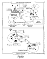
- Figure 6 illustrates a number of applications for relay stations.
- the coverage provided by a relay station may be "in-fill” to allow access to the communication network for mobile stations which may otherwise be in the shadow of other objects or otherwise unable to receive a signal of sufficient strength from the base station despite being within the normal range of the base station.
- Range extension is also shown, in which a relay station allows access when a mobile station is outside the normal data transmission range of a base station.
- in-fill shown at the top right of Figure 6 is positioning of a nomadic relay station to allow penetration of coverage within a building that could be above, at, or below ground level.
- Relays may also be used in conjunction with advanced transmission techniques to enhance gain of the communications system as explained below.
- pathloss propagation loss
- dB pathloss L
- d (metres) is the transmitter-receiver separation
- the sum of the absolute path losses experienced over the indirect link SI + ID may be less than the pathloss experienced over the direct link SD.
- multi-hop communication systems can allow for a reduction in the transmit power of transmitters which facilitate wireless transmissions, leading to a reduction in interference levels as well as decreasing exposure to electromagnetic emissions.
- the reduction in overall pathloss can be exploited to improve the received signal quality at the receiver without an increase in the overall radiated transmission power required to convey the signal.
- Multi-hop systems are suitable for use with multi-carrier transmission.
- a multi-carrier transmission system such as FDM (frequency division multiplex), OFDM (orthogonal frequency division multiplex) or DMT (discrete multi-tone)
- FDM frequency division multiplex
- OFDM orthogonal frequency division multiplex
- DMT discrete multi-tone
- a single data stream is modulated onto N parallel sub-carriers, each sub-carrier signal having its own frequency range. This allows the total bandwidth (i.e. the amount of data to be sent in a given time interval) to be divided over a plurality of sub-carriers thereby increasing the duration of each data symbol. Since each sub-carrier has a lower information rate, multi-carrier systems benefit from enhanced immunity to channel induced distortion compared with single carrier systems.
- the channel distortion correction entity within a multicarrier receiver can be of significantly lower complexity of its counterpart within a single carrier receiver when the system bandwidth is in excess of the coherence bandwidth of the channel.
- Orthogonal frequency division multiplexing is a modulation technique that is based on FDM.
- An OFDM system uses a plurality of sub-carrier frequencies which are orthogonal in a mathematical sense so that the sub-carriers' spectra may overlap without interference due to the fact they are mutually independent.
- the orthogonality of OFDM systems removes the need for guard band frequencies and thereby increases the spectral efficiency of the system.
- OFDM has been proposed and adopted for many wireless systems. It is currently used in Asymmetric Digital Subscriber Line (ADSL) connections, in some wireless LAN applications (such as WiFi devices based on the IEEE802.11a/g standard), and in wireless MAN applications such as WiMAX (based on the IEEE 802.16 standard).
- ADSL Asymmetric Digital Subscriber Line
- OFDM is often used in conjunction with channel coding, an error correction technique, to create coded orthogonal FDM or COFDM.
- COFDM is now widely used in digital telecommunications systems to improve the performance of an OFDM based system in a multipath environment where variations in the channel distortion can be seen across both subcarriers in the frequency domain and symbols in the time domain.
- the system has found use in video and audio broadcasting, such as DVB and DAB, as well as certain types of computer networking technology.
- an OFDM symbol is the composite signal of all N sub-carrier signals.
- ⁇ f is the sub-carrier separation in Hz
- c n are the modulated source signals.
- DFT Discrete Fourier Transform
- FFT Fast Fourier Transform
- OFDMA Orthogonal Frequency Division Multiple Access
- FDD frequency division duplexing
- TDD time division duplexing
- Both approaches (TDD & FDD) have their relative merits and are both well used techniques for single hop wired and wireless communication systems.
- IEEE802.16 standard incorporates both an FDD and TDD mode.
- Figure 7 illustrates the single hop TDD frame structure used in the OFDMA physical layer mode of the IEEE802.16 standard (WiMAX).
- Each frame is divided into DL and UL subframes, each being a discrete transmission interval. They are separated by Transmit/Receive and Receive/Transmit Transition Guard interval (TTG and RTG respectively).
- TTG and RTG Transmit/Receive and Receive/Transmit Transition Guard interval respectively.
- Each DL subframe starts with a preamble followed by the Frame Control Header (FCH), the DL-MAP, and the UL-MAP.
- FCH Frame Control Header
- DL-MAP DL-MAP
- UL-MAP UL-MAP
- the FCH contains the DL Frame Prefix (DLFP) to specify the burst profile and the length of the DL-MAP.
- DLFP DL Frame Prefix
- the DLFP is a data structure transmitted at the beginning of each frame and contains information regarding the current frame; it is mapped to the FCH.
- Simultaneous DL allocations can be broadcast, multicast and unicast and they can also include an allocation for another BS rather than a serving BS.
- Simultaneous ULs can be data allocations and ranging or bandwidth requests.
- the frame structure in relay station should be well designed to keep compatibility with the standardized frame structure ( Figure 7 shows an example of standardized TDD frame structure in IEEE802.16 (WiMAX) standard), and avoid interference the transmission of base station (BS), and mobile station (MS).
- BS base station
- MS mobile station
- the frame structure in RS should guarantee the communication between BS and RS, BS and MS, or RS and MS.
- the inventors have come to the realisation that communication among RSs is also important. This can allow RSs to exchange information directly, thus decreasing the signaling load in BS, and benefiting distributed algorithm implementation.
- Invention embodiments provide a feasible method to guarantee a safe communication among RSs.
- a BS will allocate one or multiple RS regions in downlink subframe or uplink subframe.
- the size of this region can be multiple OFDM symbols ( Figure 1 a ), or multiple slots ( Figure 1 b )
- the RS region is used for RS's transmission and receiving.
- BS and MS will keep quiet within RS region, thus avoiding interference.
- Preferred regulations for RS region allocation are:
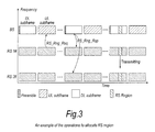
- Figure 3 shows the signalling diagram, when a relay station ( Figure 2 ) wants to request an RS region.
- RS 1# sent RS_Rng_Req to BS to request an RS region more information relating the transmission within a RS region can be enclosed in this message.
- BS will send an RS_Rng_Rsp message for response.
- BS can deny or approve RS region allocation. More information relating the transmission within a RS region can be enclosed in this message. For example, the reasons of denying, the locating and timing information of the RS region, and access method etc. If BS approve the RS region request, the corresponding RS region will be allocated in subframes.
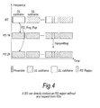
- RS regions can be specified by BS directly without any request from RS. As shown in Figure 4 , the BS directly instruct an RS region for all RSs by sending RS_Rng_Rsp message. More information can be enclosed in this message.
- the messages such as RS_Rng_Req, and RS_Rng_Rsp, can be relayed, thus allowing a multi-hop relay station to request RS regions.
- Embodiments of the present invention may be implemented in hardware, or as software modules running on one or more processors, or on a combination thereof. That is, those skilled in the art will appreciate that a microprocessor or digital signal processor (DSP) may be used in practice to implement some or all of the functionality of a transmitter embodying the present invention.
- DSP digital signal processor
- the invention may also be embodied as one or more device or apparatus programs (e.g. computer programs and computer program products) for carrying out part or all of any of the methods described herein.
- Such programs embodying the present invention may be stored on computer-readable media, or could, for example, be in the form of one or more signals.
- Such signals may be data signals downloadable from an Internet website, or provided on a carrier signal, or in any other form.
Landscapes
- Engineering & Computer Science (AREA)
- Computer Networks & Wireless Communication (AREA)
- Signal Processing (AREA)
- Mobile Radio Communication Systems (AREA)
- Radio Relay Systems (AREA)
- Time-Division Multiplex Systems (AREA)
Abstract
Description
- Currently there exists significant interest in the use of multihop techniques in packet based radio and other communication systems, where it is purported that such techniques will enable both extension in coverage range and increase in system capacity (throughput).
- In a multi-hop communication system, communication signals are sent in a communication direction along a communication path (C) from a source apparatus to a destination apparatus via one or more intermediate apparatuses.
Figure 5 illustrates a single-cell two-hop wireless communication system comprising a base station BS (known in the context of 3G communication systems as "node-B" NB) a relay node RN (also known as a relay station RS) and a user equipment UE (also known as mobile station MS). In the case where signals are being transmitted on the downlink (DL) from a base station to a destination user equipment (UE) via the relay node (RN), the base station comprises the source station (S) and the user equipment comprises the destination station (D). In the case where communication signals are being transmitted on the uplink (UL) from a user equipment (UE), via the relay node, to the base station, the user equipment comprises the source station and the base station comprises the destination station. The relay node is an example of an intermediate apparatus (I) and comprises: a receiver, operable to receive data from the source apparatus; and a transmitter, operable to transmit this data, or a derivative thereof, to the destination apparatus. - Simple analogue repeaters or digital repeaters have been used as relays to improve or provide coverage in dead spots. They can either operate in a different transmission frequency band from the source station to prevent interference between the source transmission and the repeater transmission, or they can operate at a time when there is no transmission from the source station.
-
Figure 6 illustrates a number of applications for relay stations. For fixed infrastructure, the coverage provided by a relay station may be "in-fill" to allow access to the communication network for mobile stations which may otherwise be in the shadow of other objects or otherwise unable to receive a signal of sufficient strength from the base station despite being within the normal range of the base station. "Range extension" is also shown, in which a relay station allows access when a mobile station is outside the normal data transmission range of a base station. One example of in-fill shown at the top right ofFigure 6 is positioning of a nomadic relay station to allow penetration of coverage within a building that could be above, at, or below ground level. - Other applications are nomadic relay stations which are brought into effect for temporary cover, providing access during events or emergencies/disasters. A final application shown in the bottom right of
Figure 6 provides access to a network using a relay positioned on a vehicle. - Relays may also be used in conjunction with advanced transmission techniques to enhance gain of the communications system as explained below.
- It is known that the occurrence of propagation loss, or "pathloss", due to the scattering or absorption of a radio communication as it travels through space, causes the strength of a signal to diminish. Factors which influence the pathloss between a transmitter and a receiver include: transmitter antenna height, receiver antenna height, carrier frequency, clutter type (urban, sub-urban, rural), details of morphology such as height, density, separation, terrain type (hilly, flat). The pathloss L (dB) between a transmitter and a receiver can be modelled by:

- Where d (metres) is the transmitter-receiver separation, b(db) and n are the pathloss parameters and the absolute pathloss is given by l = 10(L/10).
- The sum of the absolute path losses experienced over the indirect link SI + ID may be less than the pathloss experienced over the direct link SD. In other words it is possible for:

- Splitting a single transmission link into two shorter transmission segments therefore exploits the non-linear relationship between pathloss verses distance. From a simple theoretical analysis of the pathloss using equation (A), it can be appreciated that a reduction in the overall pathloss (and therefore an improvement, or gain, in signal strength and thus data throughput) can be achieved if a signal is sent from a source apparatus to a destination apparatus via an intermediate apparatus (e.g. relay node), rather than being sent directly from the source apparatus to the destination apparatus.
- If implemented appropriately, multi-hop communication systems can allow for a reduction in the transmit power of transmitters which facilitate wireless transmissions, leading to a reduction in interference levels as well as decreasing exposure to electromagnetic emissions. Alternatively, the reduction in overall pathloss can be exploited to improve the received signal quality at the receiver without an increase in the overall radiated transmission power required to convey the signal.
- Multi-hop systems are suitable for use with multi-carrier transmission. In a multi-carrier transmission system, such as FDM (frequency division multiplex), OFDM (orthogonal frequency division multiplex) or DMT (discrete multi-tone), a single data stream is modulated onto N parallel sub-carriers, each sub-carrier signal having its own frequency range. This allows the total bandwidth (i.e. the amount of data to be sent in a given time interval) to be divided over a plurality of sub-carriers thereby increasing the duration of each data symbol. Since each sub-carrier has a lower information rate, multi-carrier systems benefit from enhanced immunity to channel induced distortion compared with single carrier systems. This is made possible by ensuring that the transmission rate and hence bandwidth of each subcarrier is less than the coherence bandwidth of the channel. As a result, the channel distortion experienced on a signal subcarrier is frequency independent and can hence be corrected by a simple phase and amplitude correction factor. Thus the channel distortion correction entity within a multicarrier receiver can be of significantly lower complexity of its counterpart within a single carrier receiver when the system bandwidth is in excess of the coherence bandwidth of the channel.
- Orthogonal frequency division multiplexing (OFDM) is a modulation technique that is based on FDM. An OFDM system uses a plurality of sub-carrier frequencies which are orthogonal in a mathematical sense so that the sub-carriers' spectra may overlap without interference due to the fact they are mutually independent. The orthogonality of OFDM systems removes the need for guard band frequencies and thereby increases the spectral efficiency of the system. OFDM has been proposed and adopted for many wireless systems. It is currently used in Asymmetric Digital Subscriber Line (ADSL) connections, in some wireless LAN applications (such as WiFi devices based on the IEEE802.11a/g standard), and in wireless MAN applications such as WiMAX (based on the IEEE 802.16 standard). OFDM is often used in conjunction with channel coding, an error correction technique, to create coded orthogonal FDM or COFDM. COFDM is now widely used in digital telecommunications systems to improve the performance of an OFDM based system in a multipath environment where variations in the channel distortion can be seen across both subcarriers in the frequency domain and symbols in the time domain. The system has found use in video and audio broadcasting, such as DVB and DAB, as well as certain types of computer networking technology.
- In an OFDM system, a block of N modulated parallel data source signals is mapped to N orthogonal parallel sub-carriers by using an Inverse Discrete or Fast Fourier Transform algorithm (IDFT/IFFT) to form a signal known as an "OFDM symbol" in the time domain at the transmitter. Thus, an "OFDM symbol" is the composite signal of all N sub-carrier signals. An OFDM symbol can be represented mathematically as:

where Δf is the sub-carrier separation in Hz, Ts = 1/Δf is symbol time interval in seconds, and cn are the modulated source signals. The sub-carrier vector in (1) onto which each of the source signals is modulated c ∈ Cn, c = (c0, c1..cN-1) is a vector of N constellation symbols from a finite constellation. At the receiver, the received time-domain signal is transformed back to frequency domain by applying Discrete Fourier Transform (DFT) or Fast Fourier Transform (FFT) algorithm. - OFDMA (Orthogonal Frequency Division Multiple Access) is a multiple access variant of OFDM. It works by assigning a subset of sub-carriers, to an individual user. This allows simultaneous transmission from several users leading to better spectral efficiency. However, there is still the issue of allowing bi-directional communication, that is, in the uplink and download directions, without interference.
- In order to enable bi-directional communication between two nodes, two well known different approaches exist for duplexing the two (forward or download and reverse or uplink) communication links to overcome the physical limitation that a device cannot simultaneously transmit and receive on the same resource medium. The first, frequency division duplexing (FDD), involves operating the two links simultaneously but on different frequency bands by subdividing the transmission medium into two distinct bands, one for forward link and the other for reverse link communications. The second, time division duplexing (TDD), involves operating the two links on the same frequency band, but subdividing the access to the medium in time so that only the forward or the reverse link will be utilizing the medium at any one point in time. Both approaches (TDD & FDD) have their relative merits and are both well used techniques for single hop wired and wireless communication systems. For example the IEEE802.16 standard incorporates both an FDD and TDD mode.
- As an example,
Figure 7 illustrates the single hop TDD frame structure used in the OFDMA physical layer mode of the IEEE802.16 standard (WiMAX). - Each frame is divided into DL and UL subframes, each being a discrete transmission interval. They are separated by Transmit/Receive and Receive/Transmit Transition Guard interval (TTG and RTG respectively). Each DL subframe starts with a preamble followed by the Frame Control Header (FCH), the DL-MAP, and the UL-MAP.
- The FCH contains the DL Frame Prefix (DLFP) to specify the burst profile and the length of the DL-MAP. The DLFP is a data structure transmitted at the beginning of each frame and contains information regarding the current frame; it is mapped to the FCH.
- Simultaneous DL allocations can be broadcast, multicast and unicast and they can also include an allocation for another BS rather than a serving BS. Simultaneous ULs can be data allocations and ranging or bandwidth requests.
- This patent application is one of a set of ten UK patent applications filed on the same date by the same applicant with agent reference numbers P106752GB00, P106753GB00, P106754GB00, P106772GB00, P106773GB00, P106795GB00, P106796GB00, P106797GB00, P106798GB00, and P106799GB00, describing interrelated inventions proposed by the present inventors relating to communication techniques. The entire contents of each of the other nine applications is incorporated herein by way of reference thereto and copies of each of the other nine applications are filed herewith.
- The frame structure in relay station (RS) should be well designed to keep compatibility with the standardized frame structure (
Figure 7 shows an example of standardized TDD frame structure in IEEE802.16 (WiMAX) standard), and avoid interference the transmission of base station (BS), and mobile station (MS). Normally, the frame structure in RS should guarantee the communication between BS and RS, BS and MS, or RS and MS. However, the inventors have come to the realisation that communication among RSs is also important. This can allow RSs to exchange information directly, thus decreasing the signaling load in BS, and benefiting distributed algorithm implementation. - The invention is defined in the independent claims, to which reference should now be made. Advantageous embodiments are set out in the sub claims.
- Preferred features of the present invention will now be described, purely by way of example, with reference to the accompanying drawings, in which:-
-
Figure 1 shows examples of an RS region; -
Figure 2 shows a WiMAX relay system; -
Figure 3 shows an example of the operations to allocate RS region; -
Figure 4 shows that a BS can directly instruct an RS region without any request from RSs; -
Figure 5 shows a single-cell two-hop wireless communication system; -
Figure 6 shows applications of relay stations; and -
Figure 7 shows a single hop TDD frame structure used in the OFDMA physical layer mode of the IEEE 802.16 standard. - Invention embodiments provide a feasible method to guarantee a safe communication among RSs.
- To ensure a safe communication between RSs, a BS will allocate one or multiple RS regions in downlink subframe or uplink subframe. The size of this region can be multiple OFDM symbols (
Figure 1 a ), or multiple slots (Figure 1 b ) - The RS region is used for RS's transmission and receiving. BS and MS will keep quiet within RS region, thus avoiding interference. Preferred regulations for RS region allocation are:
- a. The RS region will be created and synchronized in subframes in RS, BS, and MS. The allocation and size will be instructed by BS;
- b. Within RS region, MS and BS will keep quiet;
- c. BS shall indicate which RSs have the right to transmit within the RS region;
- d. One or more RSs can transmit information within a RS region;
- e. Multiple RS regions can be allocated within the duration of downlink and uplink subframes
- The purposes of this RS region can be
- a. Exchange information (including data, and signalling) among RSs;
- b. Exchange information (including data, and signalling) between RS and MS;
- c. Exchange information (including data, and signalling) between RS and BS;
- d. Pre-decided sequences can be added into RS region for channel sensing, and synchronization;
-
Figure 3 shows the signalling diagram, when a relay station (Figure 2 ) wants to request an RS region. - In
Figure 3 ,RS 1# sent RS_Rng_Req to BS to request an RS region, more information relating the transmission within a RS region can be enclosed in this message. BS will send an RS_Rng_Rsp message for response. BS can deny or approve RS region allocation. More information relating the transmission within a RS region can be enclosed in this message. For example, the reasons of denying, the locating and timing information of the RS region, and access method etc. If BS approve the RS region request, the corresponding RS region will be allocated in subframes. - RS regions can be specified by BS directly without any request from RS. As shown in
Figure 4 , the BS directly instruct an RS region for all RSs by sending RS_Rng_Rsp message. More information can be enclosed in this message. - In multi-hop relay systems, the messages, such as RS_Rng_Req, and RS_Rng_Rsp, can be relayed, thus allowing a multi-hop relay station to request RS regions.
- In summary, the benefits of invention embodiments are:
- 1. Through the associated improvement in flexibility of frame structure (due to implement RS regions in DL subframe or UL subframe) to improve an OFDMA (such as WiMAX) system;
- 2. To afford a feasible way to allow RS to communicate each other, thus affording flexibility to the frame structure, and network deployment;
- 3. To afford more convenient for multi-hop relay systems, and distributed algorithm implementation;
- 4. A signaling mechanism is designed for the proposed RS region allocation method, which can be compatible with WiMAX standard;
- 5. More flexible for moving centralized algorithm to distributed style. A distributed implementation can release the computation and signaling load in BS;
- 6. The proposed region can be used for multiple purposes, such as channel sounding, handover, routing discovery and maintenance etc.
- Embodiments of the present invention may be implemented in hardware, or as software modules running on one or more processors, or on a combination thereof. That is, those skilled in the art will appreciate that a microprocessor or digital signal processor (DSP) may be used in practice to implement some or all of the functionality of a transmitter embodying the present invention. The invention may also be embodied as one or more device or apparatus programs (e.g. computer programs and computer program products) for carrying out part or all of any of the methods described herein. Such programs embodying the present invention may be stored on computer-readable media, or could, for example, be in the form of one or more signals. Such signals may be data signals downloadable from an Internet website, or provided on a carrier signal, or in any other form.
- The present application is a divisional application of
EP 07113557.8 EP 07113557.8 - 1. A transmission method for use in a multi-hop wireless communication system, the system comprising a source apparatus, a destination apparatus and one or more intermediate apparatuses, said source apparatus being operable to transmit information in a communication direction along a series of links forming a communication path extending from the source apparatus to the destination apparatus via the or each intermediate apparatus, and the or each intermediate apparatus being operable to receive information from a previous apparatus along the path and to transmit the received information to a subsequent apparatus along the path, the system having access to a time-frequency format for use in assigning available transmission frequency bandwidth for transmission in the communication direction during a discrete transmission interval, said format defining a plurality of transmission windows within such an interval, each window occupying a different part of that interval and having a frequency bandwidth profile within said available transmission frequency bandwidth over its part of that interval, each said window being assignable for such a transmission interval to one of said apparatuses for use in transmission, the method comprising:
- for two said apparatuses having overlapping transmission coverage areas, one of the two said apparatuses being a said intermediate apparatus, transmitting a first transmission signal from a first one of those apparatuses in a first transmission window of a particular transmission interval and transmitting a second transmission signal from the second one of those apparatuses in a second transmission window of the particular transmission interval but not in said first transmission window so that a communication apparatus located in the coverage areas of both the first and second apparatuses can receive said first transmission signal substantially without interference from said second transmission signal.
- 2. A transmission method according to
statement 1, wherein the frequency bandwidth profiles of said first and second transmission windows encompass a common part of the available transmission frequency bandwidth. - 3. A transmission method according to
statement - 4. A transmission method according to any of the preceding statements, wherein the first apparatus is a said intermediate apparatus, whereby that intermediate apparatus can transmit its own specific intermediate-apparatus information.
- 5. A transmission method according to
statement 4, wherein a further intermediate apparatus of the communication system transmits a further transmission signal during said first transmission window, so that said further intermediate apparatus can also transmit its own specific intermediate-apparatus information. - 6. A transmission method according to
statement - 7. A transmission method according to
statement - 8. A transmission method according to any of the preceding statements, wherein said first transmission signal includes data.
- 9. A transmission method according to any of the preceding statements, wherein said first transmission signal includes control information.
- 10. A transmission method according to any of the preceding statements, wherein said first transmission signal includes a transmission introduction sequence, said transmission introduction sequence preferably being a preamble-type sequence identifying its transmitting apparatus and providing training information.
- 11. A transmission method according to any of the preceding statements, wherein the second transmission signal is transmitted from the source apparatus.
- 12. A transmission method according to any of the preceding statements, comprising said first apparatus requesting assignment of said first transmission window prior to said particular transmission interval.
- 13. A transmission method according to any of the preceding statements, wherein said source apparatus assigns said first transmission window for transmission prior to said particular transmission interval.
- 14. The transmission method according to any preceding statement, wherein the time-frequency format is a format for a downlink or uplink sub-frame in a time-division-duplex communication system.
- 15. The transmission method according to any preceding statement, wherein said system is an OFDM or OFDMA system, and wherein the time-frequency format is a format for an OFDM or OFDMA downlink or uplink sub-frame of an OFDM or OFDMA time-division-duplex frame.
- 16. The transmission method according to any preceding statement, wherein each said discrete transmission interval is a sub-frame period.
- 17. The transmission method according to any preceding statement, wherein each said transmission window comprises a region in an OFDM or OFDMA frame structure.
- 18. The transmission method according to any preceding statement, wherein each said transmission window comprises a zone in an OFDM or OFDMA frame structure.
- 19. The transmission method according to any preceding statement, wherein said source apparatus is a base station.
- 20. The transmission method according to any preceding statement, wherein said source apparatus is a user terminal.
- 21. The transmission method according to any preceding statement, wherein said destination apparatus is a base station.
- 22. The transmission method according to any preceding statement, wherein said destination apparatus is a user terminal.
- 23. The transmission method according to any preceding statement, wherein the or each said intermediate apparatus is a relay station.
- 24. A multi-hop wireless communication system, comprising:
- a source apparatus, a destination apparatus and one or more intermediate apparatuses, said source apparatus being operable to transmit information in a communication direction along a series of links forming a communication path extending from the source apparatus to the destination apparatus via the or each intermediate apparatus, and the or each intermediate apparatus being operable to receive information from a previous apparatus along the path and to transmit the received information to a subsequent apparatus along the path;
- access means operable to access a time-frequency format for use in assigning available transmission frequency bandwidth for transmission in the communication direction during a discrete transmission interval, said format defining a plurality of transmission windows within such an interval, each window occupying a different part of that interval and having a frequency bandwidth profile within said available transmission frequency bandwidth over its part of that interval, each said window being assignable for such a transmission interval to one of said apparatuses for use in transmission; and
- transmission means for transmitting a first transmission signal from a first said apparatus in a first transmission window of a particular transmission interval and transmitting a second transmission signal from a second said apparatus in a second transmission window of the particular transmission interval but not in said first transmission window, one of said first and second apparatuses being a said intermediate apparatus, wherein said first and second apparatuses have overlapping transmission coverage areas, so that a communication apparatus located in the coverage areas of both said first and second apparatuses can receive said first transmission signal substantially without interference from said second transmission signal.
- 25. A suite of computer programs which, when executed on computing devices of a multi-hop wireless communication system, causes the system to carry out a transmission method, the system comprising a source apparatus, a destination apparatus and one or more intermediate apparatuses, said source apparatus being operable to transmit information in a communication direction along a series of links forming a communication path extending from the source apparatus to the destination apparatus via the or each intermediate apparatus, and the or each intermediate apparatus being operable to receive information from a previous apparatus along the path and to transmit the received information to a subsequent apparatus along the path, the system having access to a time-frequency format for use in assigning available transmission frequency bandwidth for transmission in the communication direction during a discrete transmission interval, said format defining a plurality of transmission windows within such an interval, each window occupying a different part of that interval and having a frequency bandwidth profile within said available transmission frequency bandwidth over its part of that interval, each said window being assignable for such a transmission interval to one of said apparatuses for use in transmission, the method comprising:
- for two said apparatuses having overlapping transmission coverage areas, one of two said apparatuses being a said intermediate apparatus, transmitting a first transmission signal from a first one of those apparatuses in a first transmission window of a particular transmission interval and transmitting a second transmission signal from the second one of those apparatuses in a second transmission window of the particular transmission interval but not in said first transmission window so that a communication apparatus located in the coverage areas of both the first and second apparatuses can receive said first transmission signal substantially without interference from said second transmission signal.
Claims (12)
- A multi-hop radio communication system comprising:a base station apparatus configured to transmit data in a downlink frame;an intermediate apparatus configured to relay said data received from said base station apparatus to a user equipment; andsaid user equipment configured to receive said relayed data, and transmit data in an uplink frame,wherein said base station apparatus assigns a transmission window within a frequency band which is used by said base station apparatus for transmission in said downlink frame, to said intermediate apparatus and wherein said base station apparatus and said user equipment are prohibited from transmitting radio signals from said base station apparatus and said user equipment in said transmission window.
- The multi-hop radio communication system according to claim 1, wherein said transmission window is defined by using frequency and time.
- The multi-hop radio communication system according to claim 1 or 2, wherein said transmission window is assigned to said intermediate apparatus in response to a request from said intermediate apparatus to said base station apparatus.
- The multi-hop radio communication system according to any of the preceding claims, wherein said transmission window is used for transmission from said intermediate apparatus to another intermediate apparatus or said user equipment in said downlink frame.
- The multi-hop radio communication system according to any of claims 1 to 3, wherein said transmission window is used for transmission from said intermediate apparatus to another intermediate apparatus or said base station apparatus in said uplink frame.
- A method used in a multi-hop radio communication system, said method comprising:transmitting data from a base station apparatus in a downlink frame;relaying, by an intermediate apparatus, said data received from said base station apparatus to a user equipment; andreceiving, by said user equipment, said relayed data from said intermediate apparatus, and transmitting data in an uplink frame from said user equipment, andassigning, by said base station apparatus, a transmission window within a frequency band, which frequency band is used by said base station apparatus for transmission in said downlink frame, to said intermediate apparatus, and prohibiting the transmission of radio signals from said base station apparatus and said user equipment in said transmission window.
- A base station apparatus used in a multi-hop radio communication system, said base station apparatus comprising:a transmitting unit configured to transmit data that is relayed by an intermediate apparatus to a user equipment in a downlink frame and to prohibit transmission of radio signals in a transmission window that is assigned to said intermediate apparatus by said base station apparatus, said transmission window being within a frequency band which is used by said base station apparatus for transmission in said downlink frame.
- An intermediate apparatus used in a multi-hop radio communication system, said intermediate apparatus comprising:a receiving unit configured to receive data from a base station apparatus in a downlink frame; anda transmitting unit configured to transmit data to said base station apparatus or a user equipment for relaying in a transmission window that is assigned by said base station apparatus, said transmission window being within a frequency band which is used by said base station apparatus for transmission in said downlink frame, wherein transmission from said base station apparatus and said user equipment is prohibited in said transmission window.
- A user equipment used in a multi-hop radio communication system, user equipment comprising:a receiving unit configured to receive relayed data from an intermediate apparatus that relays data transmitted from a base station apparatus in a downlink frame; anda transmitting unit configured to transmit data in an uplink frame and prohibited from transmitting radio signals in a transmission window that is assigned to said intermediate apparatus by said base station apparatus, said transmission window being within a frequency band which is used by said base station apparatus for transmission in said downlink frame.
- A transmission method for use in a multi-hop wireless communication system, the system comprising a source apparatus, a destination apparatus and one or more intermediate apparatuses, said source apparatus being operable to transmit information in a communication direction along a series of links forming a communication path extending from the source apparatus to the destination apparatus via the one or more intermediate apparatuses, and the one or more intermediate apparatuses being operable to receive information from a previous apparatus along the path and to transmit the received information to a subsequent apparatus along the path, the system using a time-frequency format for transmission during a transmission period, with a plurality of transmission windows being provided within the transmission period, each window occupying a different part, said windows being assignable for transmission in the transmission period, the method comprising:transmitting a first transmission signal from a first apparatus, corresponding to one of said one or more intermediate apparatuses, in a first transmission window of a particular transmission period; andtransmitting a second transmission signal from a second apparatus, corresponding to said source apparatus or another intermediate apparatus of said one or more intermediate apparatuses, in a second transmission window of the particular transmission period but not in said first transmission window, the first apparatus and the second apparatus having overlapping transmission coverage areas, wherein said intermediate apparatus transmits its own intermediate-apparatus information in said first transmission window.
- The transmission method according to claim 10, wherein a further intermediate apparatus of said communication system transmits a further signal in said first transmission window.
- The transmission method according to claim 11, wherein said further intermediate apparatus transmits its own intermediate-apparatus information in said first transmission window.
Applications Claiming Priority (2)
| Application Number | Priority Date | Filing Date | Title |
|---|---|---|---|
| GB0616482A GB2440986A (en) | 2006-08-18 | 2006-08-18 | Wireless multi-hop communication system |
| EP07113557A EP1890505A1 (en) | 2006-08-18 | 2007-07-31 | Multi-hop wireless communication system |
Related Parent Applications (2)
| Application Number | Title | Priority Date | Filing Date |
|---|---|---|---|
| EP07113557.8 Division | 2007-07-31 | ||
| EP07113557A Division EP1890505A1 (en) | 2006-08-18 | 2007-07-31 | Multi-hop wireless communication system |
Publications (2)
| Publication Number | Publication Date |
|---|---|
| EP2146537A2 true EP2146537A2 (en) | 2010-01-20 |
| EP2146537A3 EP2146537A3 (en) | 2011-09-21 |
Family
ID=37081244
Family Applications (3)
| Application Number | Title | Priority Date | Filing Date |
|---|---|---|---|
| EP07113557A Withdrawn EP1890505A1 (en) | 2006-08-18 | 2007-07-31 | Multi-hop wireless communication system |
| EP09173068A Withdrawn EP2146536A3 (en) | 2006-08-18 | 2007-07-31 | Multi-hop wireless communication system |
| EP09173075A Withdrawn EP2146537A3 (en) | 2006-08-18 | 2007-07-31 | Multi-hop wireless communication system |
Family Applications Before (2)
| Application Number | Title | Priority Date | Filing Date |
|---|---|---|---|
| EP07113557A Withdrawn EP1890505A1 (en) | 2006-08-18 | 2007-07-31 | Multi-hop wireless communication system |
| EP09173068A Withdrawn EP2146536A3 (en) | 2006-08-18 | 2007-07-31 | Multi-hop wireless communication system |
Country Status (7)
| Country | Link |
|---|---|
| US (2) | US7957257B2 (en) |
| EP (3) | EP1890505A1 (en) |
| JP (2) | JP2008048422A (en) |
| KR (2) | KR100939405B1 (en) |
| CN (3) | CN101507314B (en) |
| GB (1) | GB2440986A (en) |
| TW (2) | TW200816694A (en) |
Cited By (1)
| Publication number | Priority date | Publication date | Assignee | Title |
|---|---|---|---|---|
| CN107431951A (en) * | 2015-02-19 | 2017-12-01 | 西格弗克斯公司 | Method and system for the radio communication between terminal and half-duplex base station |
Families Citing this family (29)
| Publication number | Priority date | Publication date | Assignee | Title |
|---|---|---|---|---|
| GB2440981A (en) * | 2006-08-18 | 2008-02-20 | Fujitsu Ltd | Wireless multi-hop communication system |
| GB0616476D0 (en) | 2006-08-18 | 2006-09-27 | Fujitsu Ltd | Communication systems |
| GB2440986A (en) * | 2006-08-18 | 2008-02-20 | Fujitsu Ltd | Wireless multi-hop communication system |
| GB2440984A (en) * | 2006-08-18 | 2008-02-20 | Fujitsu Ltd | Wireless multi-hop communication system |
| TW201028024A (en) * | 2006-08-18 | 2010-07-16 | Fujitsu Ltd | Communication systems |
| GB2441574A (en) * | 2006-09-08 | 2008-03-12 | Fujitsu Ltd | Network entry to a multi-hop wireless communication system |
| KR101404677B1 (en) * | 2007-09-03 | 2014-06-09 | 삼성전자주식회사 | Method and apparatus for using efficient radio resource in wireless communication system based relay |
| EP2106074B1 (en) * | 2008-03-27 | 2010-09-22 | Fujitsu Limited | Wireless communication systems |
| JP5353049B2 (en) * | 2008-04-28 | 2013-11-27 | 富士通株式会社 | Wireless communication method and wireless communication apparatus |
| JP2011523310A (en) * | 2008-06-12 | 2011-08-04 | ノーテル・ネットワークス・リミテッド | Method for using relay station with spectrum aggregation, communication station, base station and communication system |
| CN102138288B (en) * | 2008-08-27 | 2014-03-12 | 京瓷株式会社 | Radio relay station and radio relay method |
| US8848594B2 (en) * | 2008-12-10 | 2014-09-30 | Blackberry Limited | Method and apparatus for discovery of relay nodes |
| US8514768B2 (en) * | 2008-12-11 | 2013-08-20 | Lg Electronics Inc. | Method and apparatus for transmitting reference signal performed by relay station in wireless communication system |
| US8402334B2 (en) * | 2008-12-17 | 2013-03-19 | Research In Motion Limited | System and method for hybrid automatic repeat request (HARQ) functionality in a relay node |
| US8311061B2 (en) | 2008-12-17 | 2012-11-13 | Research In Motion Limited | System and method for multi-user multiplexing |
| US8355388B2 (en) * | 2008-12-17 | 2013-01-15 | Research In Motion Limited | System and method for initial access to relays |
| US8040904B2 (en) * | 2008-12-17 | 2011-10-18 | Research In Motion Limited | System and method for autonomous combining |
| US20100150022A1 (en) * | 2008-12-17 | 2010-06-17 | Research In Motion Corporation | System and Method for a Relay Protocol Stack |
| US8446856B2 (en) * | 2008-12-19 | 2013-05-21 | Research In Motion Limited | System and method for relay node selection |
| US8265128B2 (en) * | 2008-12-19 | 2012-09-11 | Research In Motion Limited | Multiple-input multiple-output (MIMO) with relay nodes |
| US8335466B2 (en) | 2008-12-19 | 2012-12-18 | Research In Motion Limited | System and method for resource allocation |
| US8472868B2 (en) * | 2009-05-06 | 2013-06-25 | Telefonaktiebolaget Lm Ericsson (Publ) | Method and apparatus for MIMO repeater chains in a wireless communication network |
| CN102461306B (en) * | 2009-06-12 | 2015-11-25 | 诺基亚公司 | Be convenient to the method and apparatus of via node communication |
| US8929274B2 (en) | 2009-08-12 | 2015-01-06 | Lg Electronics Inc. | Relay station and method of relay station transmitting backhaul uplink signal |
| JP5440052B2 (en) | 2009-09-11 | 2014-03-12 | ソニー株式会社 | Relay station apparatus, base station apparatus, mobile station apparatus, and radio communication system |
| EP2589162B1 (en) * | 2010-06-30 | 2016-08-10 | Telefonaktiebolaget LM Ericsson (publ) | Reduction of interference in relay systems |
| US9001714B2 (en) * | 2011-09-06 | 2015-04-07 | Broadcom Corporation | Ethernet physical layer device using time division duplex |
| US9998210B2 (en) | 2012-06-17 | 2018-06-12 | Lg Electronics Inc. | Apparatus for transceiving signals using a TDD (time division duplex) frame structure in a wireless communication system and method thereof |
| CN114245391A (en) * | 2021-11-26 | 2022-03-25 | 中国信息通信研究院 | Wireless communication information transmission method and equipment |
Family Cites Families (51)
| Publication number | Priority date | Publication date | Assignee | Title |
|---|---|---|---|---|
| DE3403715A1 (en) | 1984-02-03 | 1985-08-08 | Licentia Patent-Verwaltungs-Gmbh, 6000 Frankfurt | DIGITAL CELL RADIO SYSTEM WITH TIME MULTIPLEX |
| US5748676A (en) * | 1995-05-01 | 1998-05-05 | Norand Corporation | Network utilizing modified preambles that support antenna diversity |
| US5719868A (en) * | 1995-10-05 | 1998-02-17 | Rockwell International | Dynamic distributed, multi-channel time division multiple access slot assignment method for a network of nodes |
| US6236647B1 (en) | 1998-02-24 | 2001-05-22 | Tantivy Communications, Inc. | Dynamic frame size adjustment and selective reject on a multi-link channel to improve effective throughput and bit error rate |
| US6370384B1 (en) * | 1998-07-30 | 2002-04-09 | Airnet Communications Corporation | Frequency re-use planning for wireless communications system using wireless translating repeaters |
| US7006530B2 (en) | 2000-12-22 | 2006-02-28 | Wi-Lan, Inc. | Method and system for adaptively obtaining bandwidth allocation requests |
| US7158784B1 (en) | 2000-03-31 | 2007-01-02 | Aperto Networks, Inc. | Robust topology wireless communication using broadband access points |
| US6701129B1 (en) | 2000-09-27 | 2004-03-02 | Nortel Networks Limited | Receiver based adaptive modulation scheme |
| JP3967084B2 (en) * | 2001-02-26 | 2007-08-29 | 株式会社日立国際電気 | TDMA relay system |
| JP2002335204A (en) * | 2001-05-09 | 2002-11-22 | Nippon Telegr & Teleph Corp <Ntt> | Method for communication between base stations |
| DE60117202D1 (en) | 2001-09-03 | 2006-04-20 | St Microelectronics Nv | A method and apparatus for estimating the speed of a mobile terminal in a wireless communication system |
| CA2415132C (en) * | 2001-12-28 | 2007-07-03 | Ntt Docomo, Inc. | Radio communication system, base station, relay station, mobile station, and packet transmission control method |
| GB0200237D0 (en) * | 2002-01-07 | 2002-02-20 | Imec Inter Uni Micro Electr | Wireless cellular network architecture |
| US7096274B1 (en) | 2002-02-12 | 2006-08-22 | 3Com Corporation | Optimum frame size predictor for wireless Local Area Network |
| CN1290352C (en) * | 2002-05-27 | 2006-12-13 | 株式会社Ntt都科摩 | Mobile communication system, transmitting station, receivingstation, relay station, communication path determining method, and communication path determining program |
| JP2004040568A (en) | 2002-07-04 | 2004-02-05 | Denso Corp | Radio communications terminal |
| KR100474302B1 (en) * | 2002-09-07 | 2005-03-10 | 엘지전자 주식회사 | Buffer control method of radio link control layer |
| US7580394B2 (en) | 2002-11-27 | 2009-08-25 | Nokia Corporation | System and method for collision-free transmission scheduling in a network |
| US20040109428A1 (en) | 2002-12-09 | 2004-06-10 | Srikanth Krishnamurthy | Method and apparatus for resource allocation for multiple traffic classes in wireless ad-hoc networks |
| US7583619B2 (en) | 2002-12-16 | 2009-09-01 | Nortel Networks Limited | Wireless access communications network |
| JP4118699B2 (en) * | 2003-02-17 | 2008-07-16 | 日本電信電話株式会社 | Wireless communication method and wireless communication system |
| SE0301048D0 (en) * | 2003-04-07 | 2003-04-07 | Ericsson Telefon Ab L M | RLC window reconfiguration |
| TWI342682B (en) * | 2003-05-28 | 2011-05-21 | Ericsson Telefon Ab L M | Method and system for wireless communication networks using relaying |
| US7903538B2 (en) * | 2003-08-06 | 2011-03-08 | Intel Corporation | Technique to select transmission parameters |
| US7400856B2 (en) | 2003-09-03 | 2008-07-15 | Motorola, Inc. | Method and apparatus for relay facilitated communications |
| CA2540846C (en) * | 2003-11-19 | 2010-01-12 | Samsung Electronics Co., Ltd. | Apparatus and method for transmitting and receiving common control information in a wireless communication system |
| AU2003298477B2 (en) * | 2003-12-30 | 2008-10-02 | Nokia Technologies Oy | Communication system using relay base stations with asymmetric data links |
| JP2005252677A (en) * | 2004-03-04 | 2005-09-15 | Kddi Corp | Base station and relay communication apparatus in multihop cellular system, and radio resource allocating method |
| WO2005125250A1 (en) * | 2004-06-22 | 2005-12-29 | Nortel Networks Limited | Soft handoff in ofdma system |
| EP3537681B1 (en) * | 2004-06-24 | 2020-10-07 | Apple Inc. | Preambles in ofdma system |
| JP2006033207A (en) | 2004-07-14 | 2006-02-02 | Nec Corp | Position information providing system, radio base station device, position information providing method used for both, and program thereof |
| WO2006012554A2 (en) | 2004-07-23 | 2006-02-02 | Wireless Valley Communications, Inc. | System, method, and apparatus for determining and using the position of wireless devices or infrastructure for wireless network enhancements |
| US7864659B2 (en) * | 2004-08-02 | 2011-01-04 | Interdigital Technology Corporation | Quality control scheme for multiple-input multiple-output (MIMO) orthogonal frequency division multiplexing (OFDM) systems |
| JP4494134B2 (en) * | 2004-09-01 | 2010-06-30 | Kddi株式会社 | Wireless communication system, relay station apparatus and base station apparatus |
| DE602004006624T2 (en) | 2004-09-13 | 2008-01-31 | Alcatel Lucent | Estimation of the transmission quality in a radio network |
| US7852954B2 (en) * | 2004-09-30 | 2010-12-14 | Lg Electronics, Inc. | Method of transmitting data and estimating channel information in OFDM/OFDMA mobile communications system |
| KR100810290B1 (en) | 2004-12-14 | 2008-03-07 | 삼성전자주식회사 | Method and system for allocation data burst in a wireless communication system |
| KR100584409B1 (en) * | 2004-12-29 | 2006-05-26 | 삼성전자주식회사 | Relay commonication method for ofdma-based cellular communication system |
| US8644130B2 (en) * | 2005-03-18 | 2014-02-04 | Samsung Electronics Co., Ltd. | System and method for subcarrier allocation in a wireless multihop relay network |
| US7486928B2 (en) * | 2005-04-14 | 2009-02-03 | Kddi Corporation | Methods and apparatus for wireless communications |
| US7813695B2 (en) | 2005-05-06 | 2010-10-12 | Telefonaktiebolaget L M Ericsson (Publ) | Mobile assisted relay selection in a telecommunications system |
| JP2006319676A (en) | 2005-05-12 | 2006-11-24 | Oki Electric Ind Co Ltd | Frame transmitting method, topology acquiring method and radio communication system |
| US20080212512A1 (en) * | 2005-05-12 | 2008-09-04 | Ofer Harpek | Method and Device for Indirect Communication Within a WiMAX Network |
| KR100853422B1 (en) | 2006-01-03 | 2008-08-21 | 삼성전자주식회사 | Method for requesting and allocating of upstream bandwidth in a multi-hop relay broadband wireless access communication system |
| CN101064547B (en) * | 2006-04-27 | 2010-11-03 | 上海贝尔阿尔卡特股份有限公司 | Relay method of wireless access system and its base station, repeater facility and relay system |
| US8116256B2 (en) * | 2006-08-18 | 2012-02-14 | Fujitsu Limited | Wireless data frame structure among nodes |
| GB2440982A (en) * | 2006-08-18 | 2008-02-20 | Fujitsu Ltd | Wireless multi-hop communication system |
| US8259668B2 (en) * | 2006-08-18 | 2012-09-04 | Fujitsu Limited | Communication systems |
| GB2440985A (en) * | 2006-08-18 | 2008-02-20 | Fujitsu Ltd | Wireless multi-hop communication system |
| GB2440986A (en) * | 2006-08-18 | 2008-02-20 | Fujitsu Ltd | Wireless multi-hop communication system |
| GB2440984A (en) * | 2006-08-18 | 2008-02-20 | Fujitsu Ltd | Wireless multi-hop communication system |
-
2006
- 2006-08-18 GB GB0616482A patent/GB2440986A/en not_active Withdrawn
-
2007
- 2007-07-31 CN CN2007800307253A patent/CN101507314B/en not_active Expired - Fee Related
- 2007-07-31 TW TW096127973A patent/TW200816694A/en unknown
- 2007-07-31 EP EP07113557A patent/EP1890505A1/en not_active Withdrawn
- 2007-07-31 TW TW098141345A patent/TW201018122A/en unknown
- 2007-07-31 EP EP09173068A patent/EP2146536A3/en not_active Withdrawn
- 2007-07-31 EP EP09173075A patent/EP2146537A3/en not_active Withdrawn
- 2007-08-17 KR KR1020070083042A patent/KR100939405B1/en not_active IP Right Cessation
- 2007-08-17 CN CNA2007101419807A patent/CN101127557A/en active Pending
- 2007-08-17 US US11/840,595 patent/US7957257B2/en not_active Expired - Fee Related
- 2007-08-17 CN CN200910224590A patent/CN101714895A/en active Pending
- 2007-08-20 JP JP2007214173A patent/JP2008048422A/en active Pending
-
2009
- 2009-10-26 JP JP2009245628A patent/JP4852640B2/en not_active Expired - Fee Related
- 2009-11-13 US US12/618,211 patent/US20100128654A1/en not_active Abandoned
-
2010
- 2010-08-31 KR KR1020100084530A patent/KR101119789B1/en not_active IP Right Cessation
Cited By (2)
| Publication number | Priority date | Publication date | Assignee | Title |
|---|---|---|---|---|
| CN107431951A (en) * | 2015-02-19 | 2017-12-01 | 西格弗克斯公司 | Method and system for the radio communication between terminal and half-duplex base station |
| CN107431951B (en) * | 2015-02-19 | 2021-03-19 | 西格弗克斯公司 | Method and system for wireless communication between a terminal and a half-duplex base station |
Also Published As
| Publication number | Publication date |
|---|---|
| EP2146536A2 (en) | 2010-01-20 |
| KR20080016507A (en) | 2008-02-21 |
| US20100128654A1 (en) | 2010-05-27 |
| CN101127557A (en) | 2008-02-20 |
| JP2008048422A (en) | 2008-02-28 |
| EP2146537A3 (en) | 2011-09-21 |
| EP1890505A1 (en) | 2008-02-20 |
| CN101714895A (en) | 2010-05-26 |
| CN101507314B (en) | 2012-10-10 |
| CN101507314A (en) | 2009-08-12 |
| JP2010063123A (en) | 2010-03-18 |
| TW201018122A (en) | 2010-05-01 |
| US20080043710A1 (en) | 2008-02-21 |
| GB2440986A (en) | 2008-02-20 |
| GB0616482D0 (en) | 2006-09-27 |
| KR100939405B1 (en) | 2010-01-28 |
| EP2146536A3 (en) | 2011-09-21 |
| KR20100108502A (en) | 2010-10-07 |
| US7957257B2 (en) | 2011-06-07 |
| KR101119789B1 (en) | 2012-03-22 |
| JP4852640B2 (en) | 2012-01-11 |
| TW200816694A (en) | 2008-04-01 |
Similar Documents
| Publication | Publication Date | Title |
|---|---|---|
| US7957257B2 (en) | Communication systems | |
| KR100935283B1 (en) | Communication systems | |
| EP1890446B1 (en) | Multi-hop wireless communication | |
| EP2178325B1 (en) | Multi-hop wireless communication | |
| EP2052561B1 (en) | Multi-hop wireless communication systems | |
| US20100074164A1 (en) | Communication Systems | |
| KR101110932B1 (en) | Communication systems | |
| KR101007446B1 (en) | Communication systems | |
| KR100983942B1 (en) | Communication method for use in multi-hop wireless communication system, multi-hop wireless communication system, base station apparatus, intermediate apparatus, and use equipment |
Legal Events
| Date | Code | Title | Description |
|---|---|---|---|
| PUAI | Public reference made under article 153(3) epc to a published international application that has entered the european phase |
Free format text: ORIGINAL CODE: 0009012 |
|
| AC | Divisional application: reference to earlier application |
Ref document number: 1890505 Country of ref document: EP Kind code of ref document: P |
|
| AK | Designated contracting states |
Kind code of ref document: A2 Designated state(s): DE FR GB IT |
|
| PUAL | Search report despatched |
Free format text: ORIGINAL CODE: 0009013 |
|
| AK | Designated contracting states |
Kind code of ref document: A3 Designated state(s): DE FR GB IT |
|
| RIC1 | Information provided on ipc code assigned before grant |
Ipc: H04W 16/26 20090101AFI20110812BHEP Ipc: H04B 7/26 20060101ALI20110812BHEP |
|
| 17P | Request for examination filed |
Effective date: 20120314 |
|
| STAA | Information on the status of an ep patent application or granted ep patent |
Free format text: STATUS: THE APPLICATION HAS BEEN WITHDRAWN |
|
| 18W | Application withdrawn |
Effective date: 20120515 |