JP2011523310A - Method for using relay station with spectrum aggregation, communication station, base station and communication system - Google Patents
Method for using relay station with spectrum aggregation, communication station, base station and communication system Download PDFInfo
- Publication number
- JP2011523310A JP2011523310A JP2011512798A JP2011512798A JP2011523310A JP 2011523310 A JP2011523310 A JP 2011523310A JP 2011512798 A JP2011512798 A JP 2011512798A JP 2011512798 A JP2011512798 A JP 2011512798A JP 2011523310 A JP2011523310 A JP 2011523310A
- Authority
- JP
- Japan
- Prior art keywords
- frequency
- frequency subband
- subband
- signal
- base station
- Prior art date
- Legal status (The legal status is an assumption and is not a legal conclusion. Google has not performed a legal analysis and makes no representation as to the accuracy of the status listed.)
- Pending
Links
Images


Classifications
-
- H—ELECTRICITY
- H04—ELECTRIC COMMUNICATION TECHNIQUE
- H04L—TRANSMISSION OF DIGITAL INFORMATION, e.g. TELEGRAPHIC COMMUNICATION
- H04L5/00—Arrangements affording multiple use of the transmission path
- H04L5/003—Arrangements for allocating sub-channels of the transmission path
- H04L5/0037—Inter-user or inter-terminal allocation
- H04L5/0039—Frequency-contiguous, i.e. with no allocation of frequencies for one user or terminal between the frequencies allocated to another
-
- A—HUMAN NECESSITIES
- A61—MEDICAL OR VETERINARY SCIENCE; HYGIENE
- A61K—PREPARATIONS FOR MEDICAL, DENTAL OR TOILETRY PURPOSES
- A61K31/00—Medicinal preparations containing organic active ingredients
- A61K31/33—Heterocyclic compounds
- A61K31/395—Heterocyclic compounds having nitrogen as a ring hetero atom, e.g. guanethidine or rifamycins
- A61K31/435—Heterocyclic compounds having nitrogen as a ring hetero atom, e.g. guanethidine or rifamycins having six-membered rings with one nitrogen as the only ring hetero atom
- A61K31/44—Non condensed pyridines; Hydrogenated derivatives thereof
- A61K31/455—Nicotinic acids, e.g. niacin; Derivatives thereof, e.g. esters, amides
-
- A—HUMAN NECESSITIES
- A61—MEDICAL OR VETERINARY SCIENCE; HYGIENE
- A61K—PREPARATIONS FOR MEDICAL, DENTAL OR TOILETRY PURPOSES
- A61K31/00—Medicinal preparations containing organic active ingredients
- A61K31/33—Heterocyclic compounds
- A61K31/395—Heterocyclic compounds having nitrogen as a ring hetero atom, e.g. guanethidine or rifamycins
- A61K31/54—Heterocyclic compounds having nitrogen as a ring hetero atom, e.g. guanethidine or rifamycins having six-membered rings with at least one nitrogen and one sulfur as the ring hetero atoms, e.g. sulthiame
-
- A—HUMAN NECESSITIES
- A61—MEDICAL OR VETERINARY SCIENCE; HYGIENE
- A61K—PREPARATIONS FOR MEDICAL, DENTAL OR TOILETRY PURPOSES
- A61K45/00—Medicinal preparations containing active ingredients not provided for in groups A61K31/00 - A61K41/00
- A61K45/06—Mixtures of active ingredients without chemical characterisation, e.g. antiphlogistics and cardiaca
-
- A—HUMAN NECESSITIES
- A61—MEDICAL OR VETERINARY SCIENCE; HYGIENE
- A61K—PREPARATIONS FOR MEDICAL, DENTAL OR TOILETRY PURPOSES
- A61K9/00—Medicinal preparations characterised by special physical form
- A61K9/20—Pills, tablets, discs, rods
- A61K9/2072—Pills, tablets, discs, rods characterised by shape, structure or size; Tablets with holes, special break lines or identification marks; Partially coated tablets; Disintegrating flat shaped forms
- A61K9/2077—Tablets comprising drug-containing microparticles in a substantial amount of supporting matrix; Multiparticulate tablets
- A61K9/2081—Tablets comprising drug-containing microparticles in a substantial amount of supporting matrix; Multiparticulate tablets with microcapsules or coated microparticles according to A61K9/50
-
- A—HUMAN NECESSITIES
- A61—MEDICAL OR VETERINARY SCIENCE; HYGIENE
- A61K—PREPARATIONS FOR MEDICAL, DENTAL OR TOILETRY PURPOSES
- A61K9/00—Medicinal preparations characterised by special physical form
- A61K9/20—Pills, tablets, discs, rods
- A61K9/2072—Pills, tablets, discs, rods characterised by shape, structure or size; Tablets with holes, special break lines or identification marks; Partially coated tablets; Disintegrating flat shaped forms
- A61K9/2086—Layered tablets, e.g. bilayer tablets; Tablets of the type inert core-active coat
- A61K9/209—Layered tablets, e.g. bilayer tablets; Tablets of the type inert core-active coat containing drug in at least two layers or in the core and in at least one outer layer
-
- H—ELECTRICITY
- H04—ELECTRIC COMMUNICATION TECHNIQUE
- H04B—TRANSMISSION
- H04B7/00—Radio transmission systems, i.e. using radiation field
- H04B7/14—Relay systems
- H04B7/15—Active relay systems
- H04B7/155—Ground-based stations
- H04B7/15528—Control of operation parameters of a relay station to exploit the physical medium
- H04B7/15542—Selecting at relay station its transmit and receive resources
-
- H—ELECTRICITY
- H04—ELECTRIC COMMUNICATION TECHNIQUE
- H04L—TRANSMISSION OF DIGITAL INFORMATION, e.g. TELEGRAPHIC COMMUNICATION
- H04L25/00—Baseband systems
- H04L25/02—Details ; arrangements for supplying electrical power along data transmission lines
- H04L25/20—Repeater circuits; Relay circuits
-
- H—ELECTRICITY
- H04—ELECTRIC COMMUNICATION TECHNIQUE
- H04L—TRANSMISSION OF DIGITAL INFORMATION, e.g. TELEGRAPHIC COMMUNICATION
- H04L27/00—Modulated-carrier systems
- H04L27/26—Systems using multi-frequency codes
- H04L27/2601—Multicarrier modulation systems
- H04L27/2626—Arrangements specific to the transmitter only
-
- H—ELECTRICITY
- H04—ELECTRIC COMMUNICATION TECHNIQUE
- H04L—TRANSMISSION OF DIGITAL INFORMATION, e.g. TELEGRAPHIC COMMUNICATION
- H04L27/00—Modulated-carrier systems
- H04L27/26—Systems using multi-frequency codes
- H04L27/2601—Multicarrier modulation systems
- H04L27/2647—Arrangements specific to the receiver only
-
- H—ELECTRICITY
- H04—ELECTRIC COMMUNICATION TECHNIQUE
- H04L—TRANSMISSION OF DIGITAL INFORMATION, e.g. TELEGRAPHIC COMMUNICATION
- H04L5/00—Arrangements affording multiple use of the transmission path
- H04L5/0001—Arrangements for dividing the transmission path
- H04L5/0003—Two-dimensional division
- H04L5/0005—Time-frequency
- H04L5/0007—Time-frequency the frequencies being orthogonal, e.g. OFDM(A), DMT
-
- H—ELECTRICITY
- H04—ELECTRIC COMMUNICATION TECHNIQUE
- H04L—TRANSMISSION OF DIGITAL INFORMATION, e.g. TELEGRAPHIC COMMUNICATION
- H04L5/00—Arrangements affording multiple use of the transmission path
- H04L5/003—Arrangements for allocating sub-channels of the transmission path
-
- H—ELECTRICITY
- H04—ELECTRIC COMMUNICATION TECHNIQUE
- H04L—TRANSMISSION OF DIGITAL INFORMATION, e.g. TELEGRAPHIC COMMUNICATION
- H04L5/00—Arrangements affording multiple use of the transmission path
- H04L5/14—Two-way operation using the same type of signal, i.e. duplex
-
- H—ELECTRICITY
- H04—ELECTRIC COMMUNICATION TECHNIQUE
- H04W—WIRELESS COMMUNICATION NETWORKS
- H04W52/00—Power management, e.g. TPC [Transmission Power Control], power saving or power classes
- H04W52/04—TPC
- H04W52/06—TPC algorithms
- H04W52/14—Separate analysis of uplink or downlink
- H04W52/143—Downlink power control
-
- H—ELECTRICITY
- H04—ELECTRIC COMMUNICATION TECHNIQUE
- H04W—WIRELESS COMMUNICATION NETWORKS
- H04W52/00—Power management, e.g. TPC [Transmission Power Control], power saving or power classes
- H04W52/04—TPC
- H04W52/18—TPC being performed according to specific parameters
- H04W52/24—TPC being performed according to specific parameters using SIR [Signal to Interference Ratio] or other wireless path parameters
- H04W52/243—TPC being performed according to specific parameters using SIR [Signal to Interference Ratio] or other wireless path parameters taking into account interferences
-
- H—ELECTRICITY
- H04—ELECTRIC COMMUNICATION TECHNIQUE
- H04W—WIRELESS COMMUNICATION NETWORKS
- H04W72/00—Local resource management
- H04W72/04—Wireless resource allocation
- H04W72/044—Wireless resource allocation based on the type of the allocated resource
- H04W72/0453—Resources in frequency domain, e.g. a carrier in FDMA
-
- A—HUMAN NECESSITIES
- A61—MEDICAL OR VETERINARY SCIENCE; HYGIENE
- A61K—PREPARATIONS FOR MEDICAL, DENTAL OR TOILETRY PURPOSES
- A61K9/00—Medicinal preparations characterised by special physical form
- A61K9/20—Pills, tablets, discs, rods
- A61K9/28—Dragees; Coated pills or tablets, e.g. with film or compression coating
- A61K9/2886—Dragees; Coated pills or tablets, e.g. with film or compression coating having two or more different drug-free coatings; Tablets of the type inert core-drug layer-inactive layer
-
- A—HUMAN NECESSITIES
- A61—MEDICAL OR VETERINARY SCIENCE; HYGIENE
- A61K—PREPARATIONS FOR MEDICAL, DENTAL OR TOILETRY PURPOSES
- A61K9/00—Medicinal preparations characterised by special physical form
- A61K9/48—Preparations in capsules, e.g. of gelatin, of chocolate
- A61K9/50—Microcapsules having a gas, liquid or semi-solid filling; Solid microparticles or pellets surrounded by a distinct coating layer, e.g. coated microspheres, coated drug crystals
- A61K9/5005—Wall or coating material
- A61K9/5021—Organic macromolecular compounds
- A61K9/5026—Organic macromolecular compounds obtained by reactions only involving carbon-to-carbon unsaturated bonds, e.g. polyvinyl pyrrolidone, poly(meth)acrylates
-
- A—HUMAN NECESSITIES
- A61—MEDICAL OR VETERINARY SCIENCE; HYGIENE
- A61K—PREPARATIONS FOR MEDICAL, DENTAL OR TOILETRY PURPOSES
- A61K9/00—Medicinal preparations characterised by special physical form
- A61K9/48—Preparations in capsules, e.g. of gelatin, of chocolate
- A61K9/50—Microcapsules having a gas, liquid or semi-solid filling; Solid microparticles or pellets surrounded by a distinct coating layer, e.g. coated microspheres, coated drug crystals
- A61K9/5073—Microcapsules having a gas, liquid or semi-solid filling; Solid microparticles or pellets surrounded by a distinct coating layer, e.g. coated microspheres, coated drug crystals having two or more different coatings optionally including drug-containing subcoatings
-
- A—HUMAN NECESSITIES
- A61—MEDICAL OR VETERINARY SCIENCE; HYGIENE
- A61K—PREPARATIONS FOR MEDICAL, DENTAL OR TOILETRY PURPOSES
- A61K9/00—Medicinal preparations characterised by special physical form
- A61K9/48—Preparations in capsules, e.g. of gelatin, of chocolate
- A61K9/50—Microcapsules having a gas, liquid or semi-solid filling; Solid microparticles or pellets surrounded by a distinct coating layer, e.g. coated microspheres, coated drug crystals
- A61K9/5084—Mixtures of one or more drugs in different galenical forms, at least one of which being granules, microcapsules or (coated) microparticles according to A61K9/16 or A61K9/50, e.g. for obtaining a specific release pattern or for combining different drugs
-
- H—ELECTRICITY
- H04—ELECTRIC COMMUNICATION TECHNIQUE
- H04W—WIRELESS COMMUNICATION NETWORKS
- H04W84/00—Network topologies
- H04W84/02—Hierarchically pre-organised networks, e.g. paging networks, cellular networks, WLAN [Wireless Local Area Network] or WLL [Wireless Local Loop]
- H04W84/04—Large scale networks; Deep hierarchical networks
- H04W84/042—Public Land Mobile systems, e.g. cellular systems
- H04W84/047—Public Land Mobile systems, e.g. cellular systems using dedicated repeater stations
Landscapes
- Engineering & Computer Science (AREA)
- Signal Processing (AREA)
- Health & Medical Sciences (AREA)
- Computer Networks & Wireless Communication (AREA)
- Life Sciences & Earth Sciences (AREA)
- Medicinal Chemistry (AREA)
- Pharmacology & Pharmacy (AREA)
- Epidemiology (AREA)
- Chemical & Material Sciences (AREA)
- Animal Behavior & Ethology (AREA)
- General Health & Medical Sciences (AREA)
- Public Health (AREA)
- Veterinary Medicine (AREA)
- Bioinformatics & Cheminformatics (AREA)
- Power Engineering (AREA)
- Mobile Radio Communication Systems (AREA)
- Radio Relay Systems (AREA)
Abstract
第4世代(4G)とも言及されるアドバンスト国際移動通信技術(IMT)は100MHzにも及ぶ帯域幅をサポートしようとしている。現在のLTEのキャリア1つの帯域幅は高々20MHzをサポートしているにすぎない。本願はマルチキャリアの方法を開示し、本発明の各実施例は、シングルキャリアの帯域幅を複数個統合し、より広い帯域幅(>20MHz)を得るための簡易な方法を提供する。本方法は、4G以前の狭いシングルキャリアの帯域幅を使用する技術との完全な後方互換性を提供しつつ、ロングタームエボリューション(LTE)の帯域幅を、シングルキャリアにより提供されるものよりも拡張する。本発明の実施例は、LTEだけでなく、さらに一般的な他の通信規格にも適用可能である。 Advanced International Mobile Telecommunications Technology (IMT), also referred to as the fourth generation (4G), is trying to support bandwidths as high as 100 MHz. The bandwidth of one current LTE carrier only supports at most 20MHz. The present application discloses a multi-carrier method, and each embodiment of the present invention provides a simple method for integrating a plurality of single-carrier bandwidths to obtain a wider bandwidth (> 20 MHz). This method extends Long Term Evolution (LTE) bandwidth over that provided by a single carrier, while providing full backward compatibility with technologies that use narrow single carrier bandwidth prior to 4G. To do. The embodiments of the present invention can be applied not only to LTE but also to other general communication standards.
Description
本発明は、無線通信ネットワークにおいて中継を行う技術分野に関連する。 The present invention relates to the technical field of relaying in a wireless communication network.
中継局は、基地局及び移動局と通信することで、基地局及び移動局間の仲介手段(媒介手段又は中間手段)として機能する。さらに、中継局は、基地局及び次の中継局と通信することで、基地局及び次の中継局間の仲介手段として機能し、あるいは次の中継局及び移動局と通信することで、次の中継局及び移動局間の仲介手段として機能する。中継局における送信機及び受信機間の相互干渉を避けるため、通常、中継局は同じシステム動作帯域においてデータの受信及びデータの送信を同時には行うことができない。周波数分割複信(FDD)及び時分割複信(TDD)の双方の方式において、基地局から中継局へ、移動局から中継局へ、又は中継局から中継局へのリンクに異なるタイムスロットが割り当てられる。 The relay station communicates with the base station and the mobile station to function as an intermediary unit (mediation unit or intermediate unit) between the base station and the mobile station. Furthermore, the relay station functions as an intermediary means between the base station and the next relay station by communicating with the base station and the next relay station, or by communicating with the next relay station and the mobile station, It functions as an intermediary means between the relay station and the mobile station. In order to avoid mutual interference between the transmitter and the receiver in the relay station, the relay station usually cannot simultaneously receive and transmit data in the same system operating band. In both frequency division duplex (FDD) and time division duplex (TDD) systems, different time slots are assigned to the link from the base station to the relay station, from the mobile station to the relay station, or from the relay station to the relay station. It is done.
そのような半二重方式のFDD又はTDDによる中継方式の欠点は、次のとおりである。 The disadvantages of such a half-duplex FDD or TDD relay system are as follows.
1.システムの利用効率が減ってしまうこと。 1. Reduced system utilization efficiency.
2.半二重通信方式に対応するのに必要なフレーム構造の修正を要すること。 2. The frame structure necessary to support the half-duplex communication method must be modified.
3.同期型のHARQをサポートするのが困難なこと。 3. It is difficult to support synchronous HARQ.
4.全ての移動局をモニタするのが困難なこと。 Four. It is difficult to monitor all mobile stations.
本発明の課題は、これらの欠点の少なくとも1つに対処することである。 The object of the present invention is to address at least one of these drawbacks.
一実施例による方法は、
基地局と、該基地局が通信している少なくとも1つの中継局との間の通信リンクについて、第1の周波数サブバンドを割り当て、
前記基地局と、前記基地局が通信している第1群の1つ以上の移動局との間の通信リンクについて、第2の周波数サブバンドを割り当て、
少なくとも1つの中継局と、該少なくとも1つの中継局が通信している第2群の1つ以上の移動局との間の通信リンクについて、第3の周波数サブバンドを割り当て、
前記少なくとも1つの中継局が、
前記第1の周波数サブバンドにおいて信号を受信することと、前記第3の周波数サブバンドにおいて信号を送信することとを同時に行うこと、又は
前記第1の周波数サブバンドにおいて信号を送信することと、前記第3の周波数サブバンドにおいて信号を受信することとを同時に行うことの内の一方を実行するステップ
を有し、前記第1、第2及び第3の周波数サブバンドは、帯域幅を拡張するようにまとめられる重複していない複数の統合されるサブバンドである、方法である。
The method according to one embodiment is:
Assigning a first frequency subband for a communication link between a base station and at least one relay station with which the base station is communicating;
For a communication link between the base station and one or more mobile stations of the first group with which the base station is communicating, assign a second frequency subband,
Assigning a third frequency subband for a communication link between at least one relay station and one or more mobile stations of the second group with which the at least one relay station is in communication;
The at least one relay station is
Receiving a signal in the first frequency subband and simultaneously transmitting a signal in the third frequency subband, or transmitting a signal in the first frequency subband; Performing one of simultaneously receiving a signal in the third frequency subband, wherein the first, second, and third frequency subbands extend bandwidth The method is a plurality of non-overlapping integrated subbands that are grouped together.
本発明の第1形態による方法は、
基地局と、該基地局が通信している少なくとも1つの中継局との間の通信リンクについて、第1の周波数サブバンドを割り当て、
前記基地局と、前記基地局が通信している第1群の1つ以上の移動局との間の通信リンクについて、第2の周波数サブバンドを割り当て、
少なくとも1つの中継局と、該少なくとも1つの中継局が通信している第2群の1つ以上の移動局との間の通信リンクについて、第3の周波数サブバンドを割り当て、
前記少なくとも1つの中継局が、
前記第1の周波数サブバンドにおいて信号を受信することと、前記第3の周波数サブバンドにおいて信号を送信することとを同時に行うこと、又は
前記第1の周波数サブバンドにおいて信号を送信することと、前記第3の周波数サブバンドにおいて信号を受信することとを同時に行うことの内の一方を実行するステップ
を有し、前記第1、第2及び第3の周波数サブバンドは、帯域幅を拡張するようにまとめられる重複していない複数の統合されるサブバンドである、方法である。
The method according to the first aspect of the invention comprises:
Assigning a first frequency subband for a communication link between a base station and at least one relay station with which the base station is communicating;
For a communication link between the base station and one or more mobile stations of the first group with which the base station is communicating, assign a second frequency subband,
Assigning a third frequency subband for a communication link between at least one relay station and one or more mobile stations of the second group with which the at least one relay station is in communication;
The at least one relay station is
Receiving a signal in the first frequency subband and simultaneously transmitting a signal in the third frequency subband, or transmitting a signal in the first frequency subband; Performing one of simultaneously receiving a signal in the third frequency subband, wherein the first, second, and third frequency subbands extend bandwidth The method is a plurality of non-overlapping integrated subbands that are grouped together.
一実施例において、前記第1、第2及び第3の周波数サブバンドの内の1つ以上は、第1、第2及び第3のキャリア周波数をそれぞれ含む。 In one embodiment, one or more of the first, second, and third frequency subbands include first, second, and third carrier frequencies, respectively.
一実施例において、前記第1、第2及び第3のキャリア周波数の内の1つ以上は、統合され拡張された帯域幅の中の不連続的なキャリア周波数である。 In one embodiment, one or more of the first, second and third carrier frequencies are discontinuous carrier frequencies in the combined and expanded bandwidth.
一実施例において、前記第1、第2及び第3の周波数サブバンドは、統合され拡張された帯域幅の中の連続的なサブバンドである。 In one embodiment, the first, second and third frequency subbands are continuous subbands in the combined and expanded bandwidth.
一実施例において、前記第1の周波数サブバンドを割り当てる際、ダウンリンク(DL)周波数バンドにおいて第1のDL周波数サブバンドを、アップリンク(UL)周波数バンドにおいて第1のUL周波数サブバンドを割り当て、
前記第2の周波数サブバンドを割り当てる際、前記DL周波数バンドにおいて第2のDL周波数サブバンドを、前記UL周波数バンドにおいて第2のUL周波数サブバンドを割り当て、
前記第3の周波数サブバンドを割り当てる際、前記DL周波数バンドにおいて第3のDL周波数サブバンドを、前記UL周波数バンドにおいて第3のUL周波数サブバンドを割り当て、
前記少なくとも1つの中継局は、
前記第1のDL周波数サブバンドにおいて信号を受信すること、
前記第3のDL周波数サブバンドにおいて信号を送信すること、
前記第1のUL周波数サブバンドにおいて信号を送信すること、及び
前記第3のUL周波数サブバンドにおいて信号を受信すること
の内の1つ以上を同じタイムスロットの中で同時に実行する。
In one embodiment, when allocating the first frequency subband, the first DL frequency subband is allocated in the downlink (DL) frequency band, and the first UL frequency subband is allocated in the uplink (UL) frequency band. ,
When assigning the second frequency subband, assign a second DL frequency subband in the DL frequency band, assign a second UL frequency subband in the UL frequency band,
When assigning the third frequency subband, assign a third DL frequency subband in the DL frequency band, assign a third UL frequency subband in the UL frequency band,
The at least one relay station is
Receiving a signal in the first DL frequency subband;
Transmitting a signal in the third DL frequency subband;
One or more of transmitting a signal in the first UL frequency subband and receiving a signal in the third UL frequency subband are simultaneously performed in the same time slot.
一実施例において、第1のタイムスロットのダウンリンク(DL)通信において、第1の周波数サブバンド、第2の周波数サブバンド及び第3の周波数サブバンドを周波数バンドの中で割り当て、
第2のタイムスロットのアップリンク(UL)通信において、第1の周波数サブバンド、第2の周波数サブバンド及び第3の周波数サブバンドを周波数バンドの中で割り当て、
前記少なくとも1つの中継局が、
前記第1の周波数サブバンドにおいて信号を受信することと、前記第3の周波数サブバンドにおいて信号を送信することとを前記第1のタイムスロットの間に同時に行うこと、及び
前記第1の周波数サブバンドにおいて信号を送信することと、前記第3の周波数サブバンドにおいて信号を受信することとを前記第2のタイムスロットの間に同時に行うことの内の一方を実行する。
In one embodiment, in a downlink (DL) communication for a first time slot, a first frequency subband, a second frequency subband, and a third frequency subband are allocated within the frequency band;
In the uplink (UL) communication of the second time slot, the first frequency subband, the second frequency subband, and the third frequency subband are allocated in the frequency band,
The at least one relay station is
Receiving a signal in the first frequency subband and transmitting a signal in the third frequency subband simultaneously during the first time slot; and the first frequency subband One of transmitting a signal in a band and receiving a signal in the third frequency subband simultaneously during the second time slot is performed.
一実施例において、前記第1の周波数サブバンドを割り当てる際、専用のサブバンドを割り当て、前記第3の周波数サブバンドを割り当てる際、専用のサブバンドを割り当てる。
一実施例における方法は、前記第1及び第3の周波数サブバンドの少なくとも一方を、専用の第1又は第3の周波数サブバントとは異なるサブバンドにそれぞれ動的に割り当てるステップをさらに有する。
In one embodiment, when allocating the first frequency subband, a dedicated subband is allocated, and when allocating the third frequency subband, a dedicated subband is allocated.
The method in an embodiment further includes the step of dynamically allocating at least one of the first and third frequency subbands to a subband different from the dedicated first or third frequency subband.
一実施例における方法は、前記第1、第2及び第3の周波数サブバンドの少なくとも1つのサブバンドのサイズを変更するステップをさらに有する。 The method in an embodiment further comprises the step of changing the size of at least one subband of the first, second and third frequency subbands.
一実施例における方法は、前記第1、第2及び第3のキャリア周波数の少なくとも1つに含まれるキャリア数を変更するステップをさらに有する。 The method in an embodiment further includes the step of changing the number of carriers included in at least one of the first, second, and third carrier frequencies.
前記第1、第2及び第3の周波数サブバンドの各々が、10MHzより広く、30MHzより狭い。 Each of the first, second and third frequency subbands is wider than 10 MHz and narrower than 30 MHz.
一実施例において、前記中継局が、LTE方式により動作する中継局である。 In one embodiment, the relay station is a relay station that operates according to the LTE scheme.
一実施例において、前記LTE方式により動作する前記中継局が、従来の移動局の動作をサポートする。 In one embodiment, the relay station operating according to the LTE scheme supports the operation of a conventional mobile station.
一実施例における方法は、前記中継局の送信及び受信の間の干渉を減らすように、送信電力分布を制御するステップをさらに有する。 The method in an embodiment further comprises controlling a transmission power distribution so as to reduce interference between transmission and reception of the relay station.
一実施例において、前記送信電力分布を制御する前記ステップにおいて、前記中継局の送信及び受信の間のガードバンドのサイズを小さくできるように、低電力の広帯域信号よりも高電力の狭帯域信号を利用して前記第1又は第3の周波数サブバンドにより信号を送信する。 In one embodiment, in the step of controlling the transmission power distribution, a narrow band signal having a higher power than a low power broadband signal may be used to reduce a guard band size between transmission and reception of the relay station. A signal is transmitted using the first or third frequency subband.
本発明の第2形態による中継局は、
少なくとも1つのアンテナと、
前記少なくとも1つのアンテナに結合され、信号を送信する送信部と、
前記少なくとも1つのアンテナに結合され、信号を受信する受信部と、
中継部とを有する中継局であって、前記中継部は、
当該中継局が通信している基地局と当該中継局との間の通信リンクについて、第1の周波数サブバンドを割り当て、
当該中継局と、当該中継局が通信している第1群の1つ以上の移動局との間の通信リンクについて、第2の周波数サブバンドを割り当て、
前記中継部は、
前記第1の周波数サブバンドにおいて信号を受信することと、前記第2の周波数サブバンドにおいて信号を送信することとを同時に行うこと、及び
前記第1の周波数サブバンドにおいて信号を送信することと、前記第2の周波数サブバンドにおいて信号を受信することとを同時に行うことの内の一方を実行し、
前記第1及び第2の周波数サブバンドは、前記第3の周波数サブバンドとともに、帯域幅を拡張するようにまとめられる重複していない複数の統合されるサブバンドであり、前記基地局と、該基地局が通信している第2群の1つ以上の移動局との間の通信リンクを提供する、中継局である。
The relay station according to the second aspect of the present invention,
At least one antenna,
A transmitter coupled to the at least one antenna for transmitting a signal;
A receiver coupled to the at least one antenna for receiving a signal;
A relay station having a relay unit, the relay unit,
For the communication link between the base station with which the relay station is communicating and the relay station, assign a first frequency subband,
For the communication link between the relay station and one or more mobile stations of the first group with which the relay station is communicating, assign a second frequency subband,
The relay unit is
Receiving a signal in the first frequency subband simultaneously with transmitting a signal in the second frequency subband; and transmitting a signal in the first frequency subband; Performing one of simultaneously receiving signals in the second frequency subband,
The first and second frequency subbands are a plurality of non-overlapping integrated subbands that are grouped together with the third frequency subband to expand bandwidth, the base station, and A relay station that provides a communication link with one or more mobile stations of the second group with which the base station is communicating.
一実施例において、前記第1、第2及び第3の周波数サブバンドの内の1つ以上は、第1、第2及び第3のキャリア周波数をそれぞれ含んでいる。 In one embodiment, one or more of the first, second and third frequency subbands include first, second and third carrier frequencies, respectively.
一実施例において、前記第1、第2及び第3のキャリア周波数の内の1つ以上は、統合され拡張された帯域幅の中の不連続的なキャリア周波数である。 In one embodiment, one or more of the first, second and third carrier frequencies are discontinuous carrier frequencies in the combined and expanded bandwidth.
一実施例において、前記第1、第2及び第3の周波数サブバンドは、統合され拡張された帯域幅の中の連続的なサブバンドである。 In one embodiment, the first, second and third frequency subbands are continuous subbands in the combined and expanded bandwidth.
一実施例において、前記中継部が、
ダウンリンク(DL)周波数バンドにおいて第1のDL周波数サブバンドを、アップリンク(UL)周波数バンドにおいて第1のUL周波数サブバンドを割り当て、
前記DL周波数バンドにおいて第2のDL周波数サブバンドを、前記UL周波数バンドにおいて第2のUL周波数サブバンドを割り当て、
前記中継部が、
前記第1のDL周波数サブバンドにおいて信号を受信すること、前記第2のDL周波数サブバンドにおいて信号を送信すること、前記第1のUL周波数サブバンドにおいて信号を送信すること、及び前記第2のUL周波数サブバンドにおいて信号を受信することを同じタイムスロットの中で同時に実行する。
In one embodiment, the relay unit is
Assign the first DL frequency subband in the downlink (DL) frequency band and the first UL frequency subband in the uplink (UL) frequency band,
Assign a second DL frequency subband in the DL frequency band and a second UL frequency subband in the UL frequency band;
The relay unit is
Receiving a signal in the first DL frequency subband, transmitting a signal in the second DL frequency subband, transmitting a signal in the first UL frequency subband, and the second Receiving a signal in the UL frequency subband is performed simultaneously in the same time slot.
一実施例において、前記中継部が、
第1のタイムスロットのダウンリンク(DL)通信において、第1の周波数サブバンド及び第2の周波数サブバンドを周波数バンドの中で割り当て、
第2のタイムスロットのアップリンク(UL)通信において、第1の周波数サブバンド及び第2の周波数サブバンドを周波数バンドの中で割り当て、
前記中継部が、
前記第1の周波数サブバンドにおいて信号を受信することと、前記第3の周波数サブバンドにおいて信号を送信することとを前記第1のタイムスロットの間に同時に行うこと、及び
前記第1の周波数サブバンドにおいて信号を送信することと、前記第3の周波数サブバンドにおいて信号を受信することとを前記第2のタイムスロットの間に同時に行う。
In one embodiment, the relay unit is
In the downlink (DL) communication of the first time slot, the first frequency subband and the second frequency subband are allocated in the frequency band,
In the uplink (UL) communication of the second time slot, the first frequency subband and the second frequency subband are allocated in the frequency band,
The relay unit is
Receiving a signal in the first frequency subband and transmitting a signal in the third frequency subband simultaneously during the first time slot; and the first frequency subband Transmitting a signal in the band and receiving a signal in the third frequency subband are performed simultaneously during the second time slot.
一実施例において、前記中継部が、
前記第1の周波数サブバンドを専用のサブバンドとして割り当て、
前記第2の周波数サブバンドを専用のサブバンドとして割り当てる。
In one embodiment, the relay unit is
Assigning the first frequency subband as a dedicated subband;
The second frequency subband is assigned as a dedicated subband.
一実施例において、前記中継部が、前記第1及び第2の周波数サブバンドの少なくとも一方を、専用の第1又は第2の周波数サブバントとは異なるサブバンドにそれぞれ動的に割り当てる。 In one embodiment, the relay unit dynamically allocates at least one of the first and second frequency subbands to a subband different from the dedicated first or second frequency subband.
一実施例において、前記中継部が、前記第1又は第2の周波数サブバンドの少なくとも1つのサブバンドのサイズを変更する。 In one embodiment, the relay unit changes the size of at least one subband of the first or second frequency subband.
一実施例において、前記第1及び第2のキャリア周波数の少なくとも1つに含まれるキャリア数を変更する。 In one embodiment, the number of carriers included in at least one of the first and second carrier frequencies is changed.
本発明の第3形態による基地局は、
少なくとも1つのアンテナと、
前記少なくとも1つのアンテナに結合され、信号を送信する送信部と、
前記少なくとも1つのアンテナに結合され、信号を受信する受信部と、
基地局信号処理部と
を有し、前記基地局信号処理部は、
当該基地局と、当該基地局が通信している少なくとも1つの中継局との間の通信リンクについて、第1の周波数サブバンドを割り当て、
前記基地局と、前記基地局が通信している第1群の1つ以上の移動局との間の通信リンクについて、第2の周波数サブバンドを割り当て、
少なくとも1つの中継局と、該少なくとも1つの中継局が通信している第2群の1つ以上の移動局との間の通信リンクについて、第3の周波数サブバンドを割り当て、
当該基地局は、前記第1、第2及び第3の割り当てたサブバンドの位置を前記中継局に通知し、
前記第1、第2及び第3の周波数サブバンドは、帯域幅を拡張するようにまとめられる重複していない複数の統合されるサブバンドである、基地局である。
The base station according to the third aspect of the present invention is
At least one antenna,
A transmitter coupled to the at least one antenna for transmitting a signal;
A receiver coupled to the at least one antenna for receiving a signal;
A base station signal processor, and the base station signal processor
For a communication link between the base station and at least one relay station with which the base station is communicating, assign a first frequency subband,
For a communication link between the base station and one or more mobile stations of the first group with which the base station is communicating, assign a second frequency subband,
Assigning a third frequency subband for a communication link between at least one relay station and one or more mobile stations of the second group with which the at least one relay station is in communication;
The base station notifies the relay station of the position of the first, second and third assigned subbands,
The first, second, and third frequency subbands are base stations that are a plurality of non-overlapping integrated subbands that are grouped together to extend bandwidth.
一実施例において、前記第1、第2及び第3の周波数サブバンドの内の1つ以上は、第1、第2及び第3のキャリア周波数をそれぞれ含んでいる。 In one embodiment, one or more of the first, second and third frequency subbands include first, second and third carrier frequencies, respectively.
一実施例において、前記第1、第2及び第3のキャリア周波数の内の1つ以上は、統合され拡張された帯域幅の中の不連続的なキャリア周波数である。 In one embodiment, one or more of the first, second and third carrier frequencies are discontinuous carrier frequencies in the combined and expanded bandwidth.
一実施例において、前記第1、第2及び第3の周波数サブバンドは、統合され拡張された帯域幅の中の連続的なサブバンドである。 In one embodiment, the first, second and third frequency subbands are continuous subbands in the combined and expanded bandwidth.
一実施例において、ダウンリンク(DL)周波数バンドにおいて第1のDL周波数サブバンドを、アップリンク(UL)周波数バンドにおいて第1のUL周波数サブバンドを割り当て、
前記DL周波数バンドにおいて第2のDL周波数サブバンドを、前記UL周波数バンドにおいて第2のUL周波数サブバンドを割り当て、
前記DL周波数バンドにおいて第3のDL周波数サブバンドを、前記UL周波数バンドにおいて第3のUL周波数サブバンドを割り当てる。
In one embodiment, assigning a first DL frequency subband in the downlink (DL) frequency band and assigning a first UL frequency subband in the uplink (UL) frequency band;
Assign a second DL frequency subband in the DL frequency band and a second UL frequency subband in the UL frequency band;
A third DL frequency subband is allocated in the DL frequency band, and a third UL frequency subband is allocated in the UL frequency band.
一実施例において、第1のタイムスロットのダウンリンク(DL)通信において、第1の周波数サブバンド、第2の周波数サブバンド及び第3の周波数サブバンドを周波数バンドの中で割り当て、
第2のタイムスロットのアップリンク(UL)通信において、第1の周波数サブバンド、第2の周波数サブバンド及び第3の周波数サブバンドを周波数バンドの中で割り当てる。
In one embodiment, in a downlink (DL) communication for a first time slot, a first frequency subband, a second frequency subband, and a third frequency subband are allocated within the frequency band;
In the uplink (UL) communication of the second time slot, the first frequency subband, the second frequency subband, and the third frequency subband are allocated in the frequency band.
一実施例において、前記第1の周波数サブバンドを専用のサブバンドとして割り当て、
前記第3の周波数サブバンドを専用のサブバンドとして割り当てる。
In one embodiment, the first frequency subband is assigned as a dedicated subband,
The third frequency subband is assigned as a dedicated subband.
一実施例において、前記第1及び第3の周波数サブバンドの少なくとも一方を、専用の第1又は第3の周波数サブバントとは異なるサブバンドにそれぞれ動的に割り当てる。 In one embodiment, at least one of the first and third frequency subbands is dynamically assigned to a subband different from the dedicated first or third frequency subband.
一実施例において、前記第1、第2及び第3の周波数サブバンドの少なくとも1つのサブバンドのサイズを変更する。 In one embodiment, the size of at least one of the first, second and third frequency subbands is changed.
一実施例において、前記第1、第2及び第3のキャリア周波数の少なくとも1つに含まれるキャリア数を変更する。 In one embodiment, the number of carriers included in at least one of the first, second, and third carrier frequencies is changed.
本発明の第4形態による通信システムは、
少なくとも1つの基地局と、
前記少なくとも1つの基地局と通信する少なくとも1つの中継局と、
前記少なくとも1つの基地局と通信する第1群の1つ以上の移動局と、
前記少なくとも1つの中継局と通信する第2群の1つ以上の移動局と
を有する通信システムであって、
前記少なくとも1つの基地局に属する基地局と、該基地局が通信している少なくとも1つの中継局との間の通信リンクについて、第1の周波数サブバンドを割り当て、
前記基地局と、前記基地局が通信している前記第1群の1つ以上の移動局との間の通信リンクについて、第2の周波数サブバンドを割り当て、
前記少なくとも1つの中継局と、該少なくとも1つの中継局が通信している前記第2群の1つ以上の移動局との間の通信リンクについて、第3の周波数サブバンドを割り当て、
前記少なくとも1つの中継局が、
前記第1の周波数サブバンドにおいて信号を受信することと、前記第3の周波数サブバンドにおいて信号を送信することとを同時に行うこと、又は
前記第1の周波数サブバンドにおいて信号を送信することと、前記第3の周波数サブバンドにおいて信号を受信することとを同時に行うことの内の一方を実行し、
前記第1、第2及び第3の周波数サブバンドは、帯域幅を拡張するようにまとめられる重複していない複数の統合されるサブバンドである、通信システムである。
The communication system according to the fourth aspect of the present invention is
At least one base station;
At least one relay station communicating with the at least one base station;
A first group of one or more mobile stations communicating with the at least one base station;
A communication system comprising: a second group of one or more mobile stations communicating with the at least one relay station;
Assigning a first frequency subband for a communication link between a base station belonging to the at least one base station and at least one relay station with which the base station is communicating;
For a communication link between the base station and the one or more mobile stations of the first group with which the base station is communicating, assign a second frequency subband,
Assigning a third frequency subband for a communication link between the at least one relay station and the one or more mobile stations of the second group in communication with the at least one relay station;
The at least one relay station is
Receiving a signal in the first frequency subband and simultaneously transmitting a signal in the third frequency subband, or transmitting a signal in the first frequency subband; Performing one of simultaneously receiving signals in the third frequency subband,
The first, second, and third frequency subbands are communication systems that are a plurality of non-overlapping integrated subbands that are grouped together to extend bandwidth.
一実施例において、前記第1、第2及び第3の周波数サブバンドの内の1つ以上は、第1、第2及び第3のキャリア周波数をそれぞれ含んでいる。 In one embodiment, one or more of the first, second and third frequency subbands include first, second and third carrier frequencies, respectively.
一実施例において、前記第1、第2及び第3のキャリア周波数の内の1つ以上は、統合され拡張された帯域幅の中の不連続的なキャリア周波数である。 In one embodiment, one or more of the first, second and third carrier frequencies are discontinuous carrier frequencies in the combined and expanded bandwidth.
一実施例において、前記第1、第2及び第3の周波数サブバンドは、統合され拡張された帯域幅の中の連続的なサブバンドである。 In one embodiment, the first, second and third frequency subbands are continuous subbands in the combined and expanded bandwidth.
一実施例において、前記第1の周波数サブバンドを割り当てる際、ダウンリンク(DL)周波数バンドにおいて第1のDL周波数サブバンドを、アップリンク(UL)周波数バンドにおいて第1のUL周波数サブバンドを割り当て、
前記第2の周波数サブバンドを割り当てる際、前記DL周波数バンドにおいて第2のDL周波数サブバンドを、前記UL周波数バンドにおいて第2のUL周波数サブバンドを割り当て、
前記第3の周波数サブバンドを割り当てる際、前記DL周波数バンドにおいて第3のDL周波数サブバンドを、前記UL周波数バンドにおいて第3のUL周波数サブバンドを割り当て、
前記少なくとも1つの中継局は、
前記第1のDL周波数サブバンドにおいて信号を受信すること、
前記第3のDL周波数サブバンドにおいて信号を送信すること、
前記第1のUL周波数サブバンドにおいて信号を送信すること、及び
前記第3のUL周波数サブバンドにおいて信号を受信すること
の内の1つ以上を同じタイムスロットの中で同時に実行する。
In one embodiment, when allocating the first frequency subband, the first DL frequency subband is allocated in the downlink (DL) frequency band, and the first UL frequency subband is allocated in the uplink (UL) frequency band. ,
When assigning the second frequency subband, assign a second DL frequency subband in the DL frequency band, assign a second UL frequency subband in the UL frequency band,
When assigning the third frequency subband, assign a third DL frequency subband in the DL frequency band, assign a third UL frequency subband in the UL frequency band,
The at least one relay station is
Receiving a signal in the first DL frequency subband;
Transmitting a signal in the third DL frequency subband;
One or more of transmitting a signal in the first UL frequency subband and receiving a signal in the third UL frequency subband are simultaneously performed in the same time slot.
一実施例において、第1のタイムスロットのダウンリンク(DL)通信において、第1の周波数サブバンド、第2の周波数サブバンド及び第3の周波数サブバンドを周波数バンドの中で割り当て、
第2のタイムスロットのアップリンク(UL)通信において、第1の周波数サブバンド、第2の周波数サブバンド及び第3の周波数サブバンドを周波数バンドの中で割り当て、
前記少なくとも1つの中継局が、
前記第1の周波数サブバンドにおいて信号を受信することと、前記第3の周波数サブバンドにおいて信号を送信することとを前記第1のタイムスロットの間に同時に行うこと、及び
前記第1の周波数サブバンドにおいて信号を送信することと、前記第3の周波数サブバンドにおいて信号を受信することとを前記第2のタイムスロットの間に同時に行うことの内の一方を実行する。
In one embodiment, in a downlink (DL) communication for a first time slot, a first frequency subband, a second frequency subband, and a third frequency subband are allocated within the frequency band;
In the uplink (UL) communication of the second time slot, the first frequency subband, the second frequency subband, and the third frequency subband are allocated in the frequency band,
The at least one relay station is
Receiving a signal in the first frequency subband and transmitting a signal in the third frequency subband simultaneously during the first time slot; and the first frequency subband One of transmitting a signal in a band and receiving a signal in the third frequency subband simultaneously during the second time slot is performed.
一実施例において、前記第1の周波数サブバンドを割り当てる際、専用のサブバンドを割り当て、前記第3の周波数サブバンドを割り当てる際、専用のサブバンドを割り当てる。
一実施例において、前記第1及び第3の周波数サブバンドの少なくとも一方を、専用の第1又は第3の周波数サブバントとは異なるサブバンドにそれぞれ動的に割り当てる。
In one embodiment, when allocating the first frequency subband, a dedicated subband is allocated, and when allocating the third frequency subband, a dedicated subband is allocated.
In one embodiment, at least one of the first and third frequency subbands is dynamically assigned to a subband different from the dedicated first or third frequency subband.
一実施例において、前記第1、第2及び第3の周波数サブバンドの少なくとも1つのサブバンドのサイズを変更する。 In one embodiment, the size of at least one of the first, second and third frequency subbands is changed.
一実施例において、前記第1、第2及び第3のキャリア周波数の少なくとも1つに含まれるキャリア数を変更する。 In one embodiment, the number of carriers included in at least one of the first, second, and third carrier frequencies is changed.
一実施例において、前記第1、第2及び第3の周波数サブバンドの各々が、10MHzより広く、30MHzより狭い。 In one embodiment, each of the first, second, and third frequency subbands is greater than 10 MHz and less than 30 MHz.
一実施例において、前記中継局が、LTE方式により動作する中継局である。 In one embodiment, the relay station is a relay station that operates according to the LTE scheme.
一実施例において、前記LTE方式により動作する前記中継局が、従来の移動局の動作をサポートする。 In one embodiment, the relay station operating according to the LTE scheme supports the operation of a conventional mobile station.
一実施例において、前記中継局の送信及び受信の間の干渉を減らすように、送信電力分布を制御する。 In one embodiment, the transmission power distribution is controlled to reduce interference between transmission and reception of the relay station.
一実施例において、前記送信電力分布を制御する前記ステップにおいて、前記中継局の送信及び受信の間のガードバンドのサイズを小さくできるように、低電力の広帯域信号よりも高電力の狭帯域信号を利用して前記第1又は第3の周波数サブバンドにより信号を送信する。 In one embodiment, in the step of controlling the transmission power distribution, a narrow band signal having a higher power than a low power broadband signal may be used to reduce a guard band size between transmission and reception of the relay station. A signal is transmitted using the first or third frequency subband.
本発明による他の形態及び特徴は、添付図面に関連する本発明の特定の実施例の以下の説明を参照することで、当業者にとってさらに明らかになるであろう。 Other aspects and features of the present invention will become more apparent to those of ordinary skill in the art by reference to the following description of specific embodiments of the invention in connection with the accompanying drawings.
以下、添付図面を参照しながら本発明の実施例を説明する。 Embodiments of the present invention will be described below with reference to the accompanying drawings.
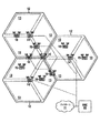
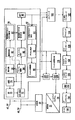
図面を参照するに、図1は、複数のセル12内の無線通信を制御する基地局コントローラ(BSC)10を示し、複数のセルは対応する基地局(BB)14により提供されている。場合によっては、セルの各々はさらに複数のセクタ13又は(不図示の)ゾーンに分割されている。一般に、各基地局は、OFDM方式により移動端末及び/又は無線端末と通信を行い、その移動端末及び/又は無線端末は、対応する基地局14に関連するセル12内に在圏している。基地局14に対して移動端末16が移動すると、チャネル状態は顕著に変動する。図示されているように、基地局14及び移動端末16は、通信における空間ダイバーシチを行うために複数のアンテナを備えている。場合によっては、中継局15が、基地局14及び移動端末16間の通信を支援する。無線端末16は、何らかのセル12、セクタ13、ゾーン(図示せず)、基地局14又は中継局15から、別のセル12、セクタ13、ゾーン(図示せず)、基地局14又は中継局15へハンドオフすることができる(18)。一実施例において、基地局14は、基地局各々と及びバックホールネットワークを介して他のネットワーク(例えば、コアネットワーク、インターネット(何れも図示せず))と通信を行う。場合によっては、基地局コントローラ10は不要である。
Referring to the drawings, FIG. 1 shows a base station controller (BSC) 10 that controls radio communications in a plurality of
第4世代(4G)とも言及される国際移動通信(IMT)アドバンスト技術は、100MHzにも及ぶ帯域幅をサポートすることを目指している。現在のLTEのキャリア1つの帯域幅は高々20MHzをサポートしているにすぎない。本願はマルチキャリアの方法を開示し、本発明の各実施例は、シングルキャリアの帯域幅を複数個統合し(キャリアアグリゲーション(carrier aggregation)を行い)、より広い帯域幅(>20MHz)を得るための簡易な方法を提供する。本方法は、4G以前の狭いシングルキャリアの帯域幅を使用する技術との完全な後方互換性を提供しつつ、ロングタームエボリューション(LTE)の帯域幅を、シングルキャリアにより提供されるものよりも拡張する。本発明の実施例は、LTEだけでなく、さらに一般的な他の通信規格にも適用可能である。 International Mobile Telecommunications (IMT) advanced technology, also referred to as 4th generation (4G), aims to support bandwidths as high as 100 MHz. The bandwidth of one current LTE carrier only supports at most 20MHz. The present application discloses a multi-carrier method, and each embodiment of the present invention integrates a plurality of single carrier bandwidths (carrier aggregation) to obtain a wider bandwidth (> 20 MHz). Provide a simple method. This method extends Long Term Evolution (LTE) bandwidth over that provided by a single carrier, while providing full backward compatibility with technologies that use narrow single carrier bandwidth prior to 4G. To do. The embodiments of the present invention can be applied not only to LTE but also to other general communication standards.
送信及び受信を同時に行うことができる中継局が、スペクトルアグリゲーション通信システムに設けられ、以下の内の1つ以上を用いてシステムパフォーマンスを改善する:
1.基地局及び少なくとも1つの中継局の間に加えて、中継局及び少なくとも1つの移動局の間に妨げられない(non−interrupted)双方向通信リンクを維持すること。
A relay station capable of transmitting and receiving simultaneously is provided in the spectrum aggregation communication system to improve system performance using one or more of the following:
1. Maintaining a non-interrupted bi-directional communication link between the base station and at least one relay station, as well as between the relay station and at least one mobile station.
2.時間分割複信(TDD)方式及び/又は周波数分割複信(FDD)方式において不連続なスペクトルアグリゲーションを行う際に専用のキャリアの中継局を使用すること。 2. Use a dedicated carrier relay station for discontinuous spectrum aggregation in time division duplex (TDD) and / or frequency division duplex (FDD).
3.TDD及び/又はFDDにおいて連続的なスペクトルアグリゲーションを行う際に専用のサブバンドの中継局を使用すること。 3. Use dedicated subband relay station for continuous spectrum aggregation in TDD and / or FDD.
4.少なくとも1つの中継局及び少なくとも1つの移動局に柔軟なチャネルリソース割当を行うこと。 Four. Flexible channel resource allocation to at least one relay station and at least one mobile station.
5.従来の移動局をサポートするためにキャリアホッピング及び/又はサブバンドホッピングを行うこと。 Five. Perform carrier hopping and / or subband hopping to support conventional mobile stations.
6.少なくとも1つの中継局における同時送受信間の干渉を軽減するように送信電力分布制御を行うこと。 6. Perform transmission power distribution control so as to reduce interference between simultaneous transmission and reception in at least one relay station.
7.同時送受信に備えて使用されるキャリア及び/又はサブバンド間の利用可能なガードバンドの間隔を制御すること。 7. Controlling the available guardband spacing between carriers and / or subbands used for simultaneous transmission and reception.
中継局は、LTEに関するセルのカバレッジ及びスループットを改善するために使用される。中継局及び移動局間の通信は、基地局及び移動局間の通信のための帯域幅を含む統合された帯域幅の中で生じるので、中継局の通信は帯域内通信又はインバンド通信(in−band communication)と考えられる。 The relay station is used to improve cell coverage and throughput for LTE. Since the communication between the relay station and the mobile station occurs in an integrated bandwidth including the bandwidth for communication between the base station and the mobile station, the communication of the relay station is in-band communication or in-band communication (in -Band communication).
本発明の実施例は、中継局を活用することを、ブロードバンドLTE−A通信システムに効率的に導入する方法を提供する。 Embodiments of the present invention provide a method for efficiently introducing a relay station into a broadband LTE-A communication system.
本発明の実施例はLTE−Aに関して説明されているが、本発明の実施例は他のタイプの通信規格にも適用可能であることが、理解されるであろう。 While embodiments of the present invention have been described with respect to LTE-A, it will be understood that embodiments of the present invention are applicable to other types of communication standards.
スペクトルアグリゲーションは、様々なバンドにおける連続的な及び/又は不連続的なスペクトルを統合(結合、併合)することで実現可能である。本発明の一実施例は、不連続的なシングルキャリアバンドを複数個統合することで実現される。そのような実施例において、分離した重複していない複数のキャリアは、基地局とその基地局が直接的に通信している移動局との間の通信(基地局から1ホップの通信)、基地局とその基地局が直接的に通信している少なくとも1つの中継局との間の通信(基地局から1ホップの通信)、及び少なくとも1つの中継局とその少なくとも1つの中継局が直接的に通信している移動局との間の通信(基地局から少なくとも2ホップの通信)に割り当てられる。1つ以上のキャリアは、基地局から移動局への通信、基地局から中継局への通信、中継局から中継局への通信、及び中継局から移動局への通信に使用される。さらに、キャリアは、基地局から1ホップ離れた中継局と基地局から2ホップ離れた中継局との間の通信に割り当てられ、及びキャリアは、基地局から2ホップ離れた中継局とその2ホップ離れた中継局が通信している1つ以上の移動局との間の通信に割り当てられる。一実施例において、統合されたスペクトルバンド内の全てのキャリアが、通信に使用されているわけではない。任意の不使用のキャリアは、使用されているキャリア同士の間のギャップになる。したがってそのような構成は、全てのキャリアが使用されているわけではないので「不連続的又は離散的(non−contiguous)」と考えられる。 Spectral aggregation can be achieved by integrating (combining, merging) continuous and / or discontinuous spectra in various bands. One embodiment of the present invention is realized by integrating a plurality of discontinuous single carrier bands. In such an embodiment, a plurality of separate non-overlapping carriers are used for communication between a base station and a mobile station with which the base station communicates directly (communication one hop from the base station), base Communication between a station and at least one relay station with which the base station is directly communicating (one hop communication from the base station), and at least one relay station and at least one of the relay stations directly Allocated to communication with a mobile station in communication (communication of at least 2 hops from the base station). One or more carriers are used for communication from the base station to the mobile station, communication from the base station to the relay station, communication from the relay station to the relay station, and communication from the relay station to the mobile station. Further, the carrier is assigned to communication between a relay station that is one hop away from the base station and a relay station that is two hops away from the base station, and the carrier is two hops away from the base station and its two hops. Allocated to communication with one or more mobile stations with which a remote relay station is communicating. In one embodiment, not all carriers in the combined spectral band are used for communication. Any unused carrier becomes a gap between the used carriers. Such a configuration is therefore considered "non-contiguous" because not all carriers are used.
本発明の一実施例は、連続的なサブバンドを複数個統合することで実現される。サブバンドは、基地局とその基地局が直接的に通信している移動局との間の通信(基地局から1ホップの通信)、基地局とその基地局が直接的に通信している少なくとも1つの中継局との間の通信(基地局から1ホップの通信)、及び少なくとも1つの中継局とその少なくとも1つの中継局が直接的に通信している移動局との間の通信(基地局から少なくとも2ホップの通信)に割り当てられる。さらに、サブバンドは、基地局から1ホップ離れた中継局と基地局から2ホップ離れた中継局との間の通信に割り当てられ、及び基地局から2ホップ離れた中継局とその2ホップ離れた中継局が通信している1つ以上の移動局との間の通信に割り当てられる。この方法により、統合されたスペクトルにおける全てのサブバンドが使用される場合、複数のサブバンドは「連続的(contiguous)」に統合されることになる。
One embodiment of the present invention is realized by integrating a plurality of continuous subbands. A subband is a communication between a base station and a mobile station with which the base station is directly communicating (1 hop communication from the base station), and at least the base station is directly communicating with the base station. Communication between one relay station (one hop communication from the base station) and communication between at least one relay station and a mobile station with which the at least one relay station is directly communicating (base station) To at least 2 hops communication). In addition, the subband is allocated for communication between the
<不連続スペクトルアグリゲーションの際の中継局>
一実施例において、不連続スペクトルアグリゲーションの場合、中継局及び基地局間の通信に専用のキャリア(キャリアR−B)を確保(予約)することで、中継局がサポートされる(中継局の動作が保証される)。一実施例において、不連続スペクトルアグリゲーションの場合、基地局及び中継局間のデータをやり取りするためのキャリア(キャリアR−B)を動的にスケジューリング(制御)することで、中継局の動作が保証される。
<Relay station for discontinuous spectrum aggregation>
In one embodiment, in the case of discontinuous spectrum aggregation, a relay station is supported by securing (reserving) a dedicated carrier (carrier RB) for communication between the relay station and the base station (operation of the relay station). Is guaranteed). In one embodiment, in the case of discontinuous spectrum aggregation, the operation of the relay station is guaranteed by dynamically scheduling (controlling) the carrier (carrier R-B) for exchanging data between the base station and the relay station. Is done.
中継局における同一バンド内(インバンド)送信/受信干渉を減らすため、基地局及び1ホップ離れた中継局間の通信に使用されるキャリア(キャリアR−B)は、隣接するキャリアから隔てられている必要がある。一実施例において、キャリア同士の間にガードバンドが設けられる。隣接キャリアは、基地局及び1ホップ離れた移動局間の通信に使用されるキャリア(キャリアB)を含む。隣接キャリアは、中継局とその中継局が通信している1つ以上の移動局との間の通信に移用されるキャリア(キャリアR−UE)も含む。キャリアR−B及びキャリアR−UEの間隔が離れるほど、インバンド送信/受信干渉を大きく低減できる。一実施例において、大きなガードバンドの代わりに干渉を減らす代替方法があり、これは例えば、後述するような送信電力分布を制御するものである。 In order to reduce in-band (in-band) transmission / reception interference at the relay station, the carrier (carrier R-B) used for communication between the base station and the relay station one hop away is separated from the adjacent carrier. Need to be. In one embodiment, a guard band is provided between the carriers. The adjacent carrier includes a carrier (carrier B) used for communication between the base station and a mobile station that is one hop away. The adjacent carrier also includes a carrier (carrier R-UE) used for communication between the relay station and one or more mobile stations with which the relay station is communicating. The in-band transmission / reception interference can be greatly reduced as the distance between the carrier RB and the carrier R-UE increases. In one embodiment, there is an alternative way to reduce interference instead of a large guard band, for example to control the transmission power distribution as described below.
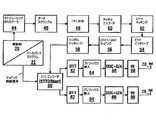
図2は、ネットワーク通信において使用される様々なレイヤを示す概略図である。物理レイヤ(PHY)は、ネットワークで使用される基本的なハードウェア通信技術の処理を含み、その物理レイヤ(PHY)において、キャリアR−UE210、キャリアB212、214及びキャリアR−B216を含む個々のキャリアが、別個に重複しないキャリアとして示されている。媒体アクセスレイヤ(MAC)220は、データリンクレイヤのサブレイヤであり、アドレシング及びチャネルアクセス制御手段を与え、ネットワークノードがネットワーク内で通信できるようにする。MAC220は、統合されたスペクトル内の全てのPHYレイヤキャリアに共通なものとして示されている。すなわち、MACレイヤは個々のキャリア全てにアクセスでき、複数のキャリアをまとめて使用することで、帯域幅を増やすことができる。共通のMACレイヤは、ネットワーク階層における上位レイヤ230と通信するように示されている。
FIG. 2 is a schematic diagram illustrating the various layers used in network communications. The physical layer (PHY) contains the processing of the basic hardware communication technology used in the network, and in that physical layer (PHY) the individual including carrier R-UE 210, carrier B212, 214 and carrier R-B216 Carriers are shown as carriers that do not overlap separately. The medium access layer (MAC) 220 is a sub-layer of the data link layer and provides addressing and channel access control means to allow network nodes to communicate within the network. The
一実施例において、1つ以上の中継局と通信する基地局は、統合されたスペクトルの中で、キャリアR−B、キャリアR−UE及びキャリアBに使用されるキャリアの位置を決定する(指定する又は割り当てる)。一実施例において、中継局は基地局に情報を提供し、その情報は、キャリアR−B及びキャリアR−UEの内の少なくとも1つに必要なキャリア数及び/又はキャリア位置を特定するためのものである。 In one embodiment, a base station that communicates with one or more relay stations determines the position of the carrier used for carrier R-B, carrier R-UE, and carrier B within the combined spectrum (designated). Or assign). In one embodiment, the relay station provides information to the base station, the information for identifying the number of carriers and / or the carrier position required for at least one of the carrier R-B and the carrier R-UE. Is.
一実施例において、1つより多いキャリアがキャリアR−Bとして指定されてもよい。キャリアR−Bの数は、基地局と少なくとも1つの中継局との間の通信に対する帯域幅の条件にしたがって調整されてもよい。 In one embodiment, more than one carrier may be designated as carrier RB. The number of carriers R-B may be adjusted according to bandwidth requirements for communication between the base station and at least one relay station.
一実施例において、1つより多いキャリアがキャリアR−UEとして指定されてもよい。キャリアR−UEの数は、中継局と中継局が通信している1つ以上の移動局との間の通信に対する帯域幅の条件にしたがって調整されてもよい。 In one embodiment, more than one carrier may be designated as the carrier R-UE. The number of carrier R-UEs may be adjusted according to bandwidth requirements for communication between the relay station and one or more mobile stations with which the relay station is communicating.
一実施例において、1つより多いキャリアがキャリアBとして指定されてもよい。キャリアBの数は、基地局と、基地局が通信している(基地局から1ホップ離れた)少なくとも1つの移動局との間の通信に対する帯域幅の条件にしたがって調整されてもよい。 In one embodiment, more than one carrier may be designated as carrier B. The number of carriers B may be adjusted according to bandwidth requirements for communication between the base station and at least one mobile station with which the base station is communicating (one hop away from the base station).
一実施例において、従来の移動局をサポートするため(従来の移動局の動作を保証するため)、限定ではないが、特に、従来の移動局に対して、統合されたスペクトルの中の特定のキャリアが割り当てられ、その特定のキャリアはLTE−Aのネットワークにおける所望のキャリア位置ではなく、キャリアR−B及びキャリアR−UEの位置(場所)は、従来の移動局及び/又は従来の移動局と通信する中継局を収容するように時間と共に変化してもよい。 In one embodiment, in order to support a conventional mobile station (to ensure the operation of a conventional mobile station), but not limited to a particular one in the integrated spectrum, especially for a conventional mobile station The carrier is assigned and that particular carrier is not the desired carrier location in the LTE-A network, and the location (location) of the carrier R-B and the carrier R-UE may be a conventional mobile station and / or a conventional mobile station. It may change over time to accommodate relay stations that communicate with.
一実施例において、従来ユーザをサポートするための中継リンクにおけるキャリア配置の変更(キャリアホッピング)は、タイムスロット毎に生じる。一実施例において、1つ以上の連続的なタイムスロット群は、統合スペクトル(スペクトルアグリゲーション)における第1のキャリア配置を含み、以後の1つ以上の連続的なタイムスロット群は従来の移動局をサポートするための統合スペクトルにおける第2のキャリア配置を含み、第2のキャリア配置は第1のキャリア配置とは異なる。異なるキャリア配置を含むタイムスロットの割当は時間と共に反復されてもよい。一実施例において、後続の反復的な第2のキャリア配置における第2のキャリア配置は、時間とともに変化してもよい。一実施例において、第1又は第2のキャリア配置によるタイムスロットの数は、異なってもよい。一実施例において、1つ以上のタイムスロットに属する2つより多い数のグループが使用され、その1つ以上のタイムスロットに属するグループの各々が、異なるキャリア配置を含んでいてもよい。 In one embodiment, a change in carrier arrangement (carrier hopping) in a relay link to support a conventional user occurs for each time slot. In one embodiment, the one or more consecutive time slot groups include a first carrier arrangement in the integrated spectrum (spectrum aggregation), and the subsequent one or more consecutive time slot groups may include conventional mobile stations. Including a second carrier arrangement in the integrated spectrum to support, wherein the second carrier arrangement is different from the first carrier arrangement. The allocation of time slots that include different carrier configurations may be repeated over time. In one example, the second carrier arrangement in subsequent repetitive second carrier arrangements may change over time. In one embodiment, the number of time slots according to the first or second carrier arrangement may be different. In one embodiment, more than two groups belonging to one or more time slots are used, and each of the groups belonging to the one or more time slots may include a different carrier arrangement.
一実施例において、統合スペクトルにおける1つ以上のキャリアが、時間分割複信方式により、中継局の受信及び送信を時間領域において分離し、従来の移動局をサポートする一方、他のキャリアは、中継局と基地局との間の通信、及び/又は中継局と1つ以上の移動局との間の通信における遮られない送信及び受信を維持する。具体例として図2を参照するに、第1のタイムスロットにおいて、中継局はキャリアR−B216により基地局からの通信を受信するが、キャリアR−B216により基地局への送信は行わず、第2のタイムスロットにおいて、中継局はキャリアR−B216により基地局へ通信信号を送信するが、キャリアR−B216により基地局から受信は行わない。 In one embodiment, one or more carriers in the integrated spectrum separate the relay station reception and transmission in the time domain by time division duplexing and support conventional mobile stations, while other carriers relay Maintain uninterrupted transmission and reception in communication between a station and a base station and / or communication between a relay station and one or more mobile stations. Referring to FIG. 2 as a specific example, in the first time slot, the relay station receives communication from the base station by carrier R-B216, but does not perform transmission to the base station by carrier R-B216. In the second time slot, the relay station transmits a communication signal to the base station by carrier R-B216, but does not receive from the base station by carrier R-B216.
<FDDインバンド中継>
基地局及び中継局間の遮られない双方向リンクに加えて、中継局及び1つ以上の移動局間の双方向リンクを維持する方法の1つは、FDDインバンド方式により実現される。
<FDD in-band relay>
In addition to the unobstructed bi-directional link between the base station and the relay station, one method of maintaining the bi-directional link between the relay station and one or more mobile stations is implemented by the FDD in-band scheme.
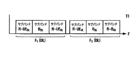
図3A及び3Bを参照するに、不連続アグリゲーションスペクトルにおけるFDDインバンド方式が示されている。 Referring to FIGS. 3A and 3B, an FDD in-band scheme in a discontinuous aggregation spectrum is shown.
図3Aは、基地局302から移動局306へのダウンリンク(DL)方向において、統合スペクトルを利用して基地局(eNB)302が中継局(RN)304を介して移動局(UE)306と通信することを示すブロック図である。特定のタイムスロットT1及びDL周波数バンドF1において、中継局304は、キャリアR−BDLにおいて基地局302からデータを受信することと、キャリアR−UEDLにおいて移動局306へデータを送信することとを同時に実行できる。基地局302から1ホップ離れている(不図示の)移動局へ基地局302が送信したデータは、インバンドスペクトルにおけるキャリアBDLにより送信される。これらの信号は、中継局304までと等しい距離ならば減衰による消失には至っていないので、移動局306に続くように示されている。ただし、このことは、キャリアBDLが、中継局が通信している移動局に達することを必ずしも意味するものではない。キャリアBDLはキャリアR−BDL及びキャリアR−UE DLと干渉するおそれがあることが、示されている。
FIG. 3A shows that in the downlink (DL) direction from the
一実施例において、様々なキャリアの位置(配置)は、各々のタイムスロットにおいて同じ位置に維持される。上述したように、一実施例において、様々なキャリアの位置は様々なタイムスロットにおいて異なる位置であってもよい。そのような実施例は、従来の移動局の動作を保証(サポート)する等の観点から有用である。 In one embodiment, the position (arrangement) of the various carriers is maintained at the same position in each time slot. As described above, in one embodiment, the positions of the various carriers may be different positions in the various time slots. Such an embodiment is useful from the viewpoint of guaranteeing (supporting) the operation of a conventional mobile station.
図3Bは、移動局306から基地局302へのアップリンク(UL)方向において、基地局(eNB)302が中継局(RN)304を介して移動局(UE)306と通信することを示すブロック図である。タイムスロットT1及びUL周波数バンドF2において、中継局304は、キャリアR−UEULにおいて移動局306からデータを受信することと、キャリアR−BULにおいて基地局302へデータを送信することとを同時に実行できる。基地局302から1ホップ離れている(不図示の)移動局が基地局302へ送信したデータは、インバンドスペクトルにおけるキャリアBULにより送信される。これらの信号は、通常、基地局付近に又は中継局付近に送信されるが、図3Bでは移動局306及び基地局302の間に示されている。キャリアBULはキャリアR−BUL及びキャリアR−UE ULと干渉するおそれがあることが、示されている。
FIG. 3B is a block diagram showing that the base station (eNB) 302 communicates with the mobile station (UE) 306 via the relay station (RN) 304 in the uplink (UL) direction from the
一実施例において、様々なキャリアの位置(配置)は、各々のタイムスロットにおいて同じ位置に維持される。上述したように、一実施例において、様々なキャリアの位置は様々なタイムスロットにおいて異なる位置であってもよい。 In one embodiment, the position (arrangement) of the various carriers is maintained at the same position in each time slot. As described above, in one embodiment, the positions of the various carriers may be different positions in the various time slots.
図3Cは図3A及び3Bに関するスペクトル例を示す。図3Cは、キャリアR−UEDL、キャリアBDL及びキャリアR−BDLを含むDL周波数バンドF1と、キャリアR−UEUL、キャリアBUL及びキャリアR−BULを含むUL周波数バンドF2とを示す。 FIG. 3C shows an example spectrum for FIGS. 3A and 3B. FIG.3C shows a DL frequency band F1 including carrier R-UE DL , carrier B DL and carrier R-B DL , and a UL frequency band F2 including carrier R-UE UL , carrier B UL and carrier R-B UL. Show.
一実施例において、キャリアR−BDL、キャリアR−UEDL、キャリアR−BUL及びキャリアR−UEULの内の何れかが、スペクトル利用効率を向上させるように、基地局及び中継局により再利用されてもよい。例えば、複数のセクタ上で送信している基地局の場合、キャリアR−BDL(又はR−BUL)が、干渉がほとんど生じないように十分に分離されている複数のセクタ内で再利用されてもよい。同様に、所与の基地局において、近接してはいない複数のセクタの中で、キャリアR−UEUL(又はR−UEUL)が、中継局及び移動局の間で再利用されてもよい。 In one embodiment, the carrier R-B DL , the carrier R-UE DL , the carrier R-B UL, and the carrier R-UE UL are controlled by the base station and the relay station so as to improve spectrum use efficiency. It may be reused. For example, in the case of a base station transmitting on multiple sectors, the carrier R-B DL (or R-B UL ) is reused in multiple sectors that are sufficiently separated so that there is little interference May be. Similarly, in a given base station, the carrier R-UE UL (or R-UE UL ) may be reused between relay stations and mobile stations among multiple sectors that are not in close proximity. .
<TDDインバンド中継>
基地局及び中継局間の遮られない双方向リンクに加えて、中継局及び1つ以上の移動局間の双方向リンクを、DL及びULサブフレームの間維持する別の方法は、TDDインバンド方式により実現される。
<TDD in-band relay>
In addition to the unobstructed bi-directional link between the base station and the relay station, another way to maintain a bi-directional link between the relay station and one or more mobile stations between DL and UL subframes is TDD in-band. It is realized by the method.
図4A及び4Bを参照するに、不連続アグリゲーションスペクトルにおけるTDDインバンド方式が示されている。 Referring to FIGS. 4A and 4B, a TDD in-band scheme in a discontinuous aggregation spectrum is shown.
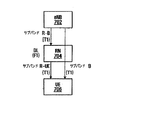
図4Aは、基地局402から移動局406へのダウンリンク(DL)方向において、基地局(eNB)402が中継局(RN)404を介して移動局(UE)406と通信することを示すブロック図である。タイムスロットT1及び周波数バンドF1において、中継局404は、キャリアR−Bにおいて基地局402からデータを受信することと、キャリアR−UEにおいて移動局406へデータを送信することとを同時に実行できる。基地局402から1ホップ離れている(不図示の)移動局へ基地局402が送信したデータは、インバンドスペクトルにおけるキャリアBにより送信される。これらの信号は、中継局404までと等しい距離ならば減衰による消失には至っていないので、移動局406に続くように示されている。ただし、このことは、キャリアBが、中継局が通信している移動局に達することを必ずしも意味するものではない。キャリアBはキャリアR−B及びキャリアR−UEと干渉するおそれがあることが、示されている。
FIG. 4A is a block diagram showing that the base station (eNB) 402 communicates with the mobile station (UE) 406 via the relay station (RN) 404 in the downlink (DL) direction from the
一実施例において、様々なキャリアの位置(配置)は、各々のタイムスロットにおいて同じ位置に維持される。上述したように、一実施例において、様々なキャリアの位置は異なる位置であってもよい。 In one embodiment, the position (arrangement) of the various carriers is maintained at the same position in each time slot. As described above, in one embodiment, the positions of the various carriers may be different positions.
図4Bは、移動局406から基地局402へのアップリンク方向において、基地局402が中継局404を介して移動局406と通信することを示すブロック図である。タイムスロットT2及び周波数バンドF1において、中継局404は、キャリアR−UEにおいて移動局406からデータを受信することと、キャリアR−Bにおいて基地局402へデータを送信することとを同時に実行できる。基地局402から1ホップ離れている(不図示の)移動局が基地局402へ送信したデータは、インバンドスペクトルにおけるキャリアBにより送信される。これらの信号は、通常、基地局付近又は中継局付近に送信されるが、図4Bでは移動局406及び基地局402の間に示されている。キャリアBはキャリアR−B及びキャリアR−UEと干渉するおそれがあることが、示されている。
FIG. 4B is a block diagram illustrating that
一実施例において、様々なキャリアの位置(配置)は、各々のタイムスロットにおいて同じ位置に維持される。上述したように、一実施例において、様々なキャリアの位置は異なる位置であってもよい。 In one embodiment, the position (arrangement) of the various carriers is maintained at the same position in each time slot. As described above, in one embodiment, the positions of the various carriers may be different positions.
1つの基地局、1つの中継局及び1つの移動局が図3A、3B、4A及び4Bに示されているが、ネットワークは複数の基地局を含み、各基地局は1つ以上の中継局及び1ホップ以上離れた移動局と通信し、各中継局は1つ以上の移動局及び移動局と通信している1つ以上の別の中継局と通信してもよいことが、理解されるべきである。 Although one base station, one relay station and one mobile station are shown in FIGS. 3A, 3B, 4A and 4B, the network includes multiple base stations, each base station including one or more relay stations and It should be understood that each relay station may communicate with one or more mobile stations and one or more other relay stations communicating with the mobile station, communicating with mobile stations that are more than one hop away It is.
一実施例において、キャリアR−B及びキャリアR−UEは、スペクトル利用効率を改善させるように、基地局及び中継局により再利用されてもよい。 In one embodiment, carrier RB and carrier R-UE may be reused by base stations and relay stations to improve spectrum utilization efficiency.
図4Cは図4A及び4Bに関する2つのタイムスロット各々の統合スペクトルを示す。図4Cは、キャリアR−B、キャリアR−UE及びキャリアBを含む周波数バンドF1によりDL通信を行う第1のタイムスロットT1と、キャリアR−B、キャリアR−UE及びキャリアBを含む周波数バンドF1によりUL通信を行う第2のタイムスロットT2とを示す。 FIG. 4C shows the combined spectrum of each of the two time slots for FIGS. 4A and 4B. FIG. 4C shows a first time slot T1 in which DL communication is performed using a frequency band F1 including carrier R-B, carrier R-UE and carrier B, and a frequency band including carrier R-B, carrier R-UE and carrier B. A second time slot T2 performing UL communication by F1 is shown.
<連続スペクトルアグリゲーションの際の中継局>
一実施例において、連続スペクトルアグリゲーションの場合、中継局及び基地局間の通信に専用のサブバンド(サブバンドR−B)を確保(予約)することで、中継局がサポートされる(中継局の動作が保証される)。一実施例において、連続スペクトルアグリゲーションの場合、基地局及び中継局間のデータをやり取りするためのサブバンド(サブバンドR−B)を動的にスケジューリング(制御)することで、中継局の動作が保証される。
<Relay station for continuous spectrum aggregation>
In one embodiment, in the case of continuous spectrum aggregation, a relay station is supported by securing (reserving) a dedicated subband (subband R-B) for communication between the relay station and the base station. Operation is guaranteed). In one embodiment, in the case of continuous spectrum aggregation, by dynamically scheduling (controlling) a subband (subband R-B) for exchanging data between the base station and the relay station, the operation of the relay station can be performed. Guaranteed.
中継局における同一バンド内(インバンド)送信/受信干渉を減らすため、基地局及び1ホップ離れた中継局間の通信に使用されるサブバンド(サブバンドR−B)は、中継局とその中継局が通信している1つ以上の移動局との間の通信に使用されるサブバンド(サブバンドR−UE)から隔てられている必要がある。サブバンドR−B及びサブバンドR−UEの間隔が離れるほど、インバンド送信/受信干渉を大きく低減できる。一実施例において、大きなガードバンドの代わりに干渉を減らす代替方法があり、これは例えば、後述するような送信電力分布を制御するものである。 In order to reduce in-band (in-band) transmission / reception interference in the relay station, the subband (subband RB) used for communication between the base station and the relay station one hop away is the relay station and its relay The station needs to be separated from the subband (subband R-UE) used for communication with one or more mobile stations with which the station is communicating. As the interval between the subband RB and the subband R-UE increases, in-band transmission / reception interference can be greatly reduced. In one embodiment, there is an alternative way to reduce interference instead of a large guard band, for example to control the transmission power distribution as described below.
図5は、ネットワーク通信において使用される様々なレイヤを示す概略図である。図5は図2に部分的に類似している。主な相違点は、図2は統合されたスペクトルの中で不連続的なキャリアを示しているが、図5は統合されたスペクトルの中でサブバンドの連続的なグループを示している点である。物理レイヤ(PHY)において、サブバンドR−UE510、サブバンドB512、514、516及びサブバンドR−B518を含む個々のサブバンドが、別個のサブバンドとして示されており、これらがまとまってスペクトル全域を占めている。MAC520は、全てのPHYレイヤサブバンドに共通なものとして示されている。共通のMACレイヤは、ネットワークの上位レイヤ530と通信するように示されている。
FIG. 5 is a schematic diagram illustrating the various layers used in network communications. FIG. 5 is partially similar to FIG. The main difference is that Figure 2 shows discontinuous carriers in the combined spectrum, while Figure 5 shows continuous groups of subbands in the combined spectrum. is there. In the physical layer (PHY), individual subbands, including subband R-UE510, subbands B512, 514, 516 and subband R-B518, are shown as separate subbands, which are grouped together across the spectrum. Accounted for. The MAC 520 is shown as common to all PHY layer subbands. The common MAC layer is shown to communicate with the
一実施例において、サブバンドR−Bのサイズは、基地局と少なくとも1つの中継局との間の通信に対する帯域幅の条件にしたがって調整されてもよい。 In one embodiment, the size of the subband RB may be adjusted according to bandwidth requirements for communication between the base station and at least one relay station.
一実施例において、サブバンドR−Bのサイズは、中継局とその中継局が通信している少なくとも1つの移動局との間の通信に対する帯域幅の条件にしたがって調整されてもよい。 In one embodiment, the size of the subband RB may be adjusted according to bandwidth requirements for communication between the relay station and at least one mobile station with which the relay station is communicating.
一実施例において、サブバンドR−Bのサイズは、基地局とその基地局から1ホップ離れた(基地局が通信している)少なくとも1つの移動局との間の通信に対する帯域幅の条件にしたがって調整されてもよい。 In one embodiment, the size of subband R-B depends on bandwidth requirements for communication between the base station and at least one mobile station that is one hop away from the base station (with which the base station is communicating). Therefore, it may be adjusted.
一実施例において、従来の移動局をサポートするため(従来の移動局の動作を保証するため)、限定ではないが、特に、従来の移動局に対して、LTE−Aのネットワークにおける所望のサブバンドには整合しない特定のキャリアが割り当てられ、サブバンドR−B及びサブバンドR−UEの位置(場所)は、時間と共に変化してもよい。 In one embodiment, to support a conventional mobile station (to ensure the operation of a conventional mobile station), but not exclusively, for a conventional mobile station, a desired sub-network in an LTE-A network may be used. A specific carrier that does not match the band is assigned, and the positions (locations) of the subband R-B and the subband R-UE may change with time.
一実施例において、従来ユーザをサポートするための中継リンクにおけるサブバンド配置の変更(サブバンドホッピング)は、タイムスロット毎に生じる。一実施例において、いくつかの連続的なタイムスロット群は、第1のサブバンド配置と、従来の移動局をサポートするための第1のサブバンドは位置とは異なる第2のサブバンド配置とを含む。タイムスロットの割当/配置は、第1及び第2のサブバンド配置に関して反復されてもよい。一実施例において、反復的な第2のサブバンド配置における第2のサブバンド配置は、時間とともに変化してもよい。一実施例において、第1又は第2のサブバンド配置によるタイムスロットの数は、異なってもよい。 In one embodiment, a change in subband arrangement (subband hopping) in a relay link to support a conventional user occurs every time slot. In one embodiment, a number of consecutive time slot groups include a first subband arrangement and a second subband arrangement in which the first subband to support a conventional mobile station is different from the position. including. Time slot assignment / arrangement may be repeated for the first and second subband arrangements. In one example, the second subband arrangement in the repetitive second subband arrangement may change over time. In one embodiment, the number of time slots according to the first or second subband arrangement may be different.
一実施例において、帯域幅の内のいくつかのサブバンドが、時間分割複信方式により、中継局の受信及び送信を時間領域において分離し、従来の移動局をサポートする一方、他のサブバンドは、中継局と基地局との間の通信、及び/又は中継局と1つ以上の移動局との間の通信における遮られない送信及び受信を維持する。具体例として図5を参照するに、第1のタイムスロットにおいて、中継局はサブバンドR−B518により基地局からの通信を受信するが、サブバンドR−B518により基地局への送信は行わず、第2のタイムスロットにおいて、中継局はサブバンドR−B518により基地局へ通信信号を送信するが、サブバンドR−B518により基地局から受信は行わない。 In one embodiment, some subbands of the bandwidth separate the reception and transmission of the relay station in the time domain by a time division duplex scheme and support conventional mobile stations, while other subbands Maintains unobstructed transmission and reception in communication between the relay station and the base station and / or communication between the relay station and one or more mobile stations. As a specific example, referring to FIG. 5, in the first time slot, the relay station receives communication from the base station by subband R-B518, but does not transmit to the base station by subband R-B518. In the second time slot, the relay station transmits a communication signal to the base station using subband R-B518, but does not receive the signal from the base station using subband R-B518.
<FDDインバンド中継>
基地局及び中継局間の遮られない双方向リンクに加えて、中継局及び1つ以上の移動局間の双方向リンクを維持する方法の1つは、FDDインバンド方式により実現される。
<FDD in-band relay>
In addition to the unobstructed bi-directional link between the base station and the relay station, one method of maintaining the bi-directional link between the relay station and one or more mobile stations is implemented by the FDD in-band scheme.
図6A及び6Bを参照するに、連続アグリゲーションスペクトルにおけるFDDインバンド方式が示されている。 Referring to FIGS. 6A and 6B, an FDD in-band scheme in a continuous aggregation spectrum is shown.
図6Aは、基地局602から移動局606へのダウンリンク方向において、基地局(eNB)602が中継局(RN)604を介して移動局(UE)606と通信することを示すブロック図である。特定のタイムスロットT1及びDL周波数バンドF1において、中継局604は、サブバンドR−BDLにおいて基地局602からデータを受信することと、サブバンドR−UEDLにおいて移動局606へデータを送信することとを同時に実行できる。基地局602から1ホップ離れている(不図示の)移動局へ基地局602が送信したデータは、インバンドスペクトルにおけるサブバンドBDLにより送信される。これらの信号は、中継局604までと等しい距離ならば減衰による消失には至っていないので、移動局606に続くように示されている。ただし、このことは、サブバンドBDLが、中継局が通信している移動局に達することを必ずしも意味するものではない。キャリアBDLはキャリアR−BDL及びキャリアR−UE DLと干渉するおそれがあることが、示されている。
FIG. 6A is a block diagram illustrating that the base station (eNB) 602 communicates with the mobile station (UE) 606 via the relay station (RN) 604 in the downlink direction from the
一実施例において、様々なサブバンドの位置(配置)は、各々のタイムスロットにおいて同じ位置に維持される。不連続的なスペクトルアグリゲーションに関して上述した方法と同様に、一実施例において、様々なサブバンドの位置は様々なタイムスロットにおいて異なる位置であってもよい。そのような実施例は、従来の移動局の動作を保証(サポート)する等の観点から有用である。 In one embodiment, the position (arrangement) of the various subbands is maintained at the same position in each time slot. Similar to the method described above for discontinuous spectral aggregation, in one embodiment, the positions of the various subbands may be different positions in the various time slots. Such an embodiment is useful from the viewpoint of guaranteeing (supporting) the operation of a conventional mobile station.
図6Bは、移動局606から基地局602へのアップリンク方向において、基地局602が中継局604を介して移動局606と通信することを示すブロック図である。タイムスロットT1及びUL周波数バンドF2において、中継局604は、サブバンドR−UEULにおいて移動局606からデータを受信することと、サブバンドR−BULにおいて基地局602へデータを送信することとを同時に実行できる。基地局602から1ホップ離れている(不図示の)移動局が基地局602へ送信したデータは、インバンドスペクトルにおけるサブバンドBULにより送信される。これらの信号は、通常、基地局付近に又は中継局付近に送信されるが、図6Bでは移動局606及び基地局602の間に示されている。キャリアBULはキャリアR−BUL及びキャリアR−UE ULと干渉するおそれがあることが、示されている。
FIG. 6B is a block diagram showing that the
一実施例において、様々なサブバンドの位置(配置)は、各々のタイムスロットにおいて同じ位置に維持される。一実施例において、様々なサブバンドの位置は異なる位置であってもよい。 In one embodiment, the position (arrangement) of the various subbands is maintained at the same position in each time slot. In one embodiment, the positions of the various subbands may be different positions.
図6Cは図6A及び6Bに関するスペクトル例を示す。図6Cは、サブバンドR−UEDL、サブバンドBDL及びサブバンドR−BDLを含むDL周波数バンドF1と、サブバンドR−UEUL、サブバンドBUL及びサブバンドR−BULを含むUL周波数バンドF2とを示す。 FIG. 6C shows an example spectrum for FIGS. 6A and 6B. FIG. 6C includes DL frequency band F1 including subband R-UE DL , subband B DL and subband R-B DL , and subband R-UE UL , subband B UL, and subband R-B UL . The UL frequency band F2 is shown.
一実施例において、サブバンドR−BDL、サブバンドR−UEDL、サブバンドR−BUL及びサブバンドR−UEULの内の何れかが、スペクトル利用効率を向上させるように、基地局及び中継局により再利用されてもよい。例えば、複数のセクタ上で送信している基地局の場合、サブバンドR−BDL(又はR−BUL)が、干渉がほとんど生じないように十分に分離されている複数のセクタ内で再利用されてもよい。同様に、所与の基地局において、近接してはいない複数のセクタの中で、サブバンドR−UEUL(又はR−UEUL)が、中継局及び移動局の間で再利用されてもよい。 In one embodiment, the base station may be configured so that any one of the subband R-B DL , the subband R-UE DL , the subband R-B UL, and the subband R-UE UL improves spectrum utilization efficiency. And may be reused by relay stations. For example, in the case of a base station transmitting on multiple sectors, the subband R-B DL (or R-B UL ) is retransmitted in multiple sectors that are sufficiently separated so that there is little interference. It may be used. Similarly, in a given base station, subband R-UE UL (or R-UE UL ) may be reused between relay stations and mobile stations among multiple sectors that are not in close proximity. Good.
<TDDインバンド中継>
基地局及び中継局間の遮られない双方向リンクに加えて、中継局及び1つ以上の移動局間の双方向リンクを、DL及びULサブフレームの間維持する別の方法は、TDDインバンド方式により実現される。
<TDD in-band relay>
In addition to the unobstructed bi-directional link between the base station and the relay station, another way to maintain a bi-directional link between the relay station and one or more mobile stations between DL and UL subframes is TDD in-band. It is realized by the method.
図7A及び7Bを参照するに、連続アグリゲーションスペクトルにおけるTDDインバンド方式が示されている。 Referring to FIGS. 7A and 7B, a TDD in-band scheme in a continuous aggregation spectrum is shown.
図7Aは、基地局702から移動局706へのダウンリンク方向において、基地局(eNB)702が中継局(RN)704を介して移動局(UE)706と通信することを示すブロック図である。DLタイムスロットT1及び周波数バンドF1において、中継局704は、サブバンドR−Bにおいて基地局702からデータを受信することと、サブバンドR−UEにおいて移動局706へデータを送信することとを同時に実行できる。基地局702から1ホップ離れている(不図示の)移動局へ基地局702が送信したデータは、インバンドスペクトルにおけるサブバンドBにより送信される。これらの信号は、中継局までと等しい距離ならば減衰による消失には至っていないので、移動局706及び基地局702の間に示されている。サブバンドBはサブバンドR−B及びサブバンドR−UEと干渉するおそれがあることが、示されている。
FIG. 7A is a block diagram illustrating that a base station (eNB) 702 communicates with a mobile station (UE) 706 via a relay station (RN) 704 in the downlink direction from the
一実施例において、このような方法は、タイムスロット各々においてサブバンドの位置が同じ位置に維持されるようにして実現可能である。あるいは、一実施例において、様々なサブバンドの位置が異なる位置になるように実現されてもよい。 In one embodiment, such a method can be implemented such that the position of the subband is maintained at the same position in each time slot. Or in one Example, it may be implement | achieved so that the position of various subbands may become a different position.
図7Bは、移動局706から基地局702へのアップリンク方向において、基地局702が中継局704を介して移動局706と通信することを示すブロック図である。ULタイムスロットT2及び周波数バンドF1において、中継局704は、サブバンドR−UEにおいて移動局706からデータを受信することと、サブバンドR−Bにおいて基地局702へデータを送信することとを同時に実行できる。基地局702から1ホップ離れている(不図示の)移動局が基地局702へ送信したデータは、インバンドスペクトルにおけるサブバンドBにより送信される。これらの信号は、通常、基地局付近又は中継局付近に送信されるが、図7Bでは移動局706及び基地局702の間に示されている。サブバンドBはサブバンドR−B及びサブバンドR−UEと干渉するおそれがあることが、示されている。
FIG. 7B is a block diagram illustrating that
一実施例において、様々なサブバンドの位置(配置)は、各々のタイムスロットにおいて同じ位置に維持される。上述したように、一実施例において、様々なサブバンドの位置は異なる位置であってもよい。 In one embodiment, the position (arrangement) of the various subbands is maintained at the same position in each time slot. As described above, in one embodiment, the positions of the various subbands may be different positions.
図7Cは図7A及び7Bに関する2つのタイムスロット各々のスペクトル例を示す。図7Cは、サブバンドR−UE、サブバンドB及びサブバンドR−Bを含む周波数バンドF1によりDL通信を行う第1のタイムスロットT1と、サブバンドR−UE、サブバンドB及びサブバンドR−Bを含む周波数バンドF1によりUL通信を行う第2のタイムスロットT2とを示す。 FIG. 7C shows an example spectrum for each of the two time slots for FIGS. 7A and 7B. FIG. 7C shows a first time slot T1 in which DL communication is performed using frequency band F1 including subband R-UE, subband B, and subband R-B, and subband R-UE, subband B, and subband R. A second time slot T2 in which UL communication is performed in a frequency band F1 including −B is shown.
1つの基地局、1つの中継局及び1つの移動局が図6A、6B、7A及び7Bに示されているが、ネットワークは複数の基地局を含み、各基地局は1つ以上の中継局及び1ホップ以上離れた移動局と通信し、各中継局は1つ以上の移動局及び移動局と通信している1つ以上の別の中継局と通信してもよいことが、理解されるべきである。 Although one base station, one relay station and one mobile station are shown in FIGS. 6A, 6B, 7A and 7B, the network includes multiple base stations, each base station including one or more relay stations and It should be understood that each relay station may communicate with one or more mobile stations and one or more other relay stations communicating with the mobile station, communicating with mobile stations that are more than one hop away It is.
一実施例において、キャリアR−B及びキャリアR−UEは、スペクトル利用効率を改善させるように、基地局及び中継局により再利用されてもよい。 In one embodiment, carrier RB and carrier R-UE may be reused by base stations and relay stations to improve spectrum utilization efficiency.
図8を参照しながら、中継局が使用する方法を説明する。本方法の第1のステップ8−1は、基地局とその基地局が通信している少なくとも1つの中継局との間の通信リンクについて、第1の周波数サブバンドを割り当てる(指定する)ことを含む。本方法の第2のステップ8−2は、基地局とその基地局が通信している1つ以上の移動局の内の第1移動局群との間の通信リンクについて、第2の周波数サブバンドを割り当てる(指定する)ことを含む。本方法の第3のステップ8−3は、少なくとも1つの中継局と、その少なくとも1つの中継局が通信している1つ以上の移動局の内の第2移動局群との間の通信リンクについて、第3の周波数サブバンドを割り当てる(指定する)ことを含む。本方法の第4のステップ8−4は、以下の手順の内の少なくとも1つを少なくとも1つの中継局が実行することを含む:第1の周波数サブバンドにより信号を受信することと、第3の周波数サブバンドにより信号を送信することとを同時に行うこと;及び第1の周波数サブバンドにより信号を送信することと、第3の周波数サブバンドにより信号を受信することとを同時に行うこと。第1、第2及び第3の周波数サブバンドは、重複していない統合される複数のサブバンドであり、これらをまとめることで帯域幅を増加させる。 A method used by the relay station will be described with reference to FIG. The first step 8-1 of the method involves assigning (specifying) a first frequency subband for a communication link between a base station and at least one relay station with which the base station is communicating. Including. The second step 8-2 of the method is for a second frequency sub-band for a communication link between a base station and a first mobile station group of one or more mobile stations with which the base station is communicating. Includes assigning (specifying) bands. The third step 8-3 of the method comprises a communication link between at least one relay station and a second group of mobile stations of one or more mobile stations with which the at least one relay station is communicating. Assigning (designating) a third frequency subband. The fourth step 8-4 of the method includes the at least one relay station performing at least one of the following procedures: receiving a signal on the first frequency subband; Simultaneously transmitting a signal on the first frequency subband; and simultaneously transmitting a signal on the first frequency subband and receiving a signal on the third frequency subband. The first, second, and third frequency subbands are a plurality of integrated subbands that do not overlap, and the bandwidth is increased by combining these subbands.
一実施例において、第1、第2及び第3の周波数サブバンドの1つ以上は、それぞれ第1、第2及び第3のキャリア周波数である。一実施例において、第1、第2又は第3のキャリア周波数の1つ以上は、統合されて増加した帯域幅の中の不連続的な帯域である。 In one embodiment, one or more of the first, second, and third frequency subbands are first, second, and third carrier frequencies, respectively. In one embodiment, one or more of the first, second, or third carrier frequencies is a discontinuous band within the combined and increased bandwidth.
一実施例において、第1、第2及び第3の周波数サブバンドは、統合されて増加した帯域幅の中の連続的な帯域である。 In one embodiment, the first, second and third frequency subbands are continuous bands in the combined and increased bandwidth.
一実施例において、第1及び第3のサブバンドの内の少なくとも1つは、専用のサブバンドである。一実施例において、第1及び第3のサブバンドの少なくとも1つは、それぞれ上記の専用の第1又は第3のサブバンドとは異なるサブバンドに動的に割り当てられる。一実施例において、第1、第2及び第3のサブバンドの少なくとも1つの帯域幅のサイズが可変であり、その帯域幅は動的に割り当てられる(指定される)。 In one embodiment, at least one of the first and third subbands is a dedicated subband. In one embodiment, at least one of the first and third subbands is dynamically assigned to a different subband than the dedicated first or third subband, respectively. In one embodiment, the size of at least one bandwidth of the first, second, and third subbands is variable and the bandwidth is dynamically allocated (specified).
FDD方式により実現する場合、第1の周波数サブバンドを割り当てる際に、ダウンリンク(DL)周波数バンドにおいて第1のDL周波数サブバンドを、及びアップリンク(UL)周波数バンドにおいて第1のUL周波数サブバンドを割り当て;第2の周波数サブバンドを割り当てる際に、DL周波数バンドにおいて第2のDL周波数サブバンドを、及びUL周波数バンドにおいて第2のUL周波数サブバンドを割り当て;第3の周波数サブバンドを割り当てる際に、DL周波数バンドにおいて第3のDL周波数サブバンドを、及びUL周波数バンドにおいて第3のUL周波数サブバンドを割り当て;少なくとも1つの中継局が、第1のDL周波数サブバンドにより信号を受信すること、第3のDL周波数サブバンドにより信号を送信すること、第1のUL周波数サブバンドにより信号を送信すること、及び第3のUL周波数サブバンドにより信号を受信することの内の1つ以上を同じタイムスロットの中で同時に実行する。 When implementing the FDD method, when assigning the first frequency subband, the first DL frequency subband in the downlink (DL) frequency band and the first UL frequency subband in the uplink (UL) frequency band Assigning a band; assigning a second DL frequency subband in the DL frequency band and a second UL frequency subband in the UL frequency band when assigning the second frequency subband; assigning a third frequency subband; When assigning, assign a third DL frequency subband in the DL frequency band and a third UL frequency subband in the UL frequency band; at least one relay station receives a signal on the first DL frequency subband Transmitting a signal on the third DL frequency subband, transmitting a signal on the first UL frequency subband, and One or more of receiving signals on the third UL frequency subband is performed simultaneously in the same time slot.
TDD方式により実現する場合、第1のタイムスロットにおいて、ダウンリンク(DL)通信に関し、第1のDL周波数サブバンド、第2の周波数サブバンド及び第3の周波数サブバンドを周波数バンドの中で割り当て、第2のタイムスロットにおいて、アップリンク(UL)通信に関し、第1のDL周波数サブバンド、第2の周波数サブバンド及び第3の周波数サブバンドを周波数バンドの中で割り当て;少なくとも1つの中継局が、第1の周波数サブバンドにより信号を受信すること、及び第3の周波数サブバンドにより信号を送信することを第1のタイムスロットの間に実行し;第1の周波数サブバンドにより信号を送信すること、及び第3の周波数サブバンドにより信号を受信することを第2のタイムスロットの間に実行する。 When implemented using the TDD method, the first DL frequency subband, the second frequency subband, and the third frequency subband are allocated in the frequency band for downlink (DL) communication in the first time slot. Assigning a first DL frequency subband, a second frequency subband and a third frequency subband within the frequency band for uplink (UL) communication in a second time slot; at least one relay station Receiving during the first time slot receiving a signal on the first frequency subband and transmitting a signal on the third frequency subband; transmitting a signal on the first frequency subband And receiving a signal on the third frequency subband during the second time slot.
中継局が通信している基地局が、上記と同様な方法を使用してもよい。一実施例において、基地局はDL及びUL通信に使用するサブバンド及び/又はキャリアを割り当てる役割を有し、そのDL及びUL通信は、基地局と中継局との間のDL及びUL通信、基地局と1ホップ離れた移動局との間のDL及びUL通信、中継局と基地局から2ホップ離れた別の中継局との間のDL及びUL通信、及び中継局とその中継局が通信している移動局との間のDL及びUL通信である。基地局がサブバンド及び/又はキャリアを割り当てると、基地局は中継局に通知を行い、中継局がどのサブバンド及び/又はキャリアにより送信/受信するかを中継局に知らせる。中継局は、その中継局が通信している移動局にその情報をさらに通知(転送)する。上述したように、基地局は、必要に応じて(例えば、従来の移動局の場合に)異なるサブバンド及び/又はキャリアを動的に割り当てる(指定する)役割を担ってもよい。
The base station with which the relay station is communicating may use the same method as described above. In one embodiment, the base station is responsible for allocating subbands and / or carriers used for DL and UL communication, and the DL and UL communication includes DL and UL communication between the base station and the relay station, DL and UL communication between a station and a
さらに、少なくとも1つの基地局、少なくとも1つの中継局及び少なくとも1つの移動局を含むシステムが、上記の本方法を協働して実行してもよい。 Furthermore, a system including at least one base station, at least one relay station and at least one mobile station may perform the above method in cooperation.
<Tx/Rxガードギャップ削減>
本発明の一実施例において、送信電力分布を制御することで、中継局における送信及び受信の間の相互干渉を減らしてもよい。
<Reducing Tx / Rx guard gap>
In one embodiment of the present invention, mutual interference between transmission and reception at the relay station may be reduced by controlling the transmission power distribution.
図9は中継局が使用する統合されたスペクトル900の一例を示し、キャリアR−B910及びキャリアR−UE920はガードバンド930により分離されている。このようなガードバンドは、使用されていない1つ以上のキャリアを含んでもよいし、あるいはある種の通信信号に使用されてもよい1つ以上のキャリアを含んでもよい。例えば、図2に関して説明したように、キャリアR−B910及びキャリアR−UE920の間の少なくとも1つのキャリアが、基地局と1ホップ離れた移動局との間の通信に使用されてもよい。
FIG. 9 shows an example of an
一実施例において、基地局からの通信の送信電力及び帯域幅を制御することで、ガードバンドを少なくする(狭くする)ことができる。キャリアR−Bにおいて送信される2つのフォーマットの信号が示されており、一方は940により示され、帯域幅が狭く及びピーク電力が高い信号であり、他方は950により示され、帯域幅が広く及びピーク電力が低い信号である。信号940は、信号950よりも高いピーク電力及び狭い帯域幅を有する。帯域幅が狭い信号940は、ガードバンド930の領域において、信号950と比較して低い電力をもたらす。例えば、図中960により示されるスペクトル位置の場合、2つの信号の基準レベルに対して、帯域幅が狭い信号940の電力は、帯域幅が広い信号950の半分のレベルに過ぎない。したがって、狭い帯域幅の信号940は、広い帯域幅の信号950と比較して、ガードバンド930内の同じ位置において、より低い電力を有するので、2つのキャリアR−B910及びキャリアR−UE920の2つのキャリア信号は、送信/受信相互干渉を同程度に低減する制御を行う際、より狭いガードバンドを使用することができる。一実施例において、狭帯域かつ高電力の信号は、所望のターゲットノード(すなわち、中継局)が基地局から遠く離れている場合に有用である。一実施例において、広帯域かつ低電力の信号は、所望のターゲットノード(すなわち、中継局)が、基地局と近接している場合に有用である。しかしながら、狭帯域幅で高電力の信号は、所望のターゲットノード(すなわち、中継局)が基地局と近接している場合に使用されてもよい。この場合、基地局及び移動局と通信する中継局が使用するキャリア同士の間で、狭いガードバンドが使用されることが望ましい。
In one embodiment, the guard band can be reduced (narrowed) by controlling the transmission power and bandwidth of communication from the base station. Signals in two formats transmitted on carrier R-B are shown, one indicated by 940, a signal with narrow bandwidth and high peak power, the other indicated by 950, with a wide bandwidth And a signal with low peak power.
一実施例において、中継局は、基地局、移動局及び他の中継局への送信に対して、同様に送信電力の分布を制御してもよい。 In one embodiment, the relay station may similarly control the distribution of transmission power for transmissions to base stations, mobile stations, and other relay stations.
<通信システムの具体的な構成要素の説明>
図10を参照するに、基地局14の具体例が示されている。概して、基地局14は、制御部20、ベースバンドプロセッサ22、送信部24、受信部26、複数のアンテナ28及びネットワークインターフェース30を含む。受信部26は、移動端末16(図11)及び中継局15(図12)に備わっている1つ以上の遠隔送信機からの情報を担う無線周波数信号を受信する。低雑音増幅器及びフィルタ(図示せず)は、協働して、処理する信号を増幅してブロードバンド干渉を除去する。ダウンコンバージョン部及びディジタル化部(図示せず)は、受信されフィルタリングされた信号を中間周波数信号又はベースバンド周波数信号にダウンコンバートし、1つ以上のディジタルストリームにディジタル化する。
<Description of specific components of communication system>
Referring to FIG. 10, a specific example of the
ベースバンドプロセッサ22は、受信及びディジタル化された信号を処理し、受信信号により搬送された情報又はデータビットを抽出する。この処理は、典型的には、復調、複合及び誤り訂正を含む。したがって、ベースバンドプロセッサ22は、一般に、1つ以上のディジタル信号プロセッサ(DSP)又は特定用途向け集積回路(ASIC)により実現される。受信した情報は、ネットワークインターフェース30を介して無線ネットワークへ送信される、あるいは基地局14のセルに在圏する他の移動端末へ直接的に又は中継局15を介して送信される。
The
送信の場合、ベースバンドプロセッサ22は、制御部20による制御にしたがって、音声、ビデオ、データ又は制御情報を表すディジタルデータを、ネットワークインターフェース30から受信し、そのデータを送信するためにエンコードする。エンコードされた信号は送信部24に出力され、所望の1つ以上の周波数を含む1つ以上のキャリア信号により変調される。電力増幅器(図示せず)は、変調されたキャリア信号を送信に適したレベルに増幅し、変調されたキャリア信号をマッチング回路(図示せず)を介してアンテナ28に運ぶ。変調及び処理の詳細については後述される。
In the case of transmission, the
図11を参照するに、移動端末16の具体例が示されている。基地局14と同様に、移動端末16は、制御部22、ベースバンドプロセッサ34、送信部36、受信部38、複数のアンテナ40及びユーザインターフェース回路42を含む。受信部38は、1つ以上の基地局14及び中継局15からの情報を運ぶ無線周波数信号を受信する。低雑音増幅器及びフィルタ(図示せず)は、協働して、処理する信号を増幅してブロードバンド干渉を除去する。ダウンコンバージョン部及びディジタル化部(図示せず)は、受信されフィルタリングされた信号を中間周波数信号又はベースバンド周波数信号にダウンコンバートし、1つ以上のディジタルストリームにディジタル化する。
Referring to FIG. 11, a specific example of the
ベースバンドプロセッサ34は、受信及びディジタル化された信号を処理し、受信信号により搬送された情報又はデータビットを抽出する。この処理は、典型的には、復調、複合及び誤り訂正を含む。したがって、ベースバンドプロセッサ22は、一般に、1つ以上のディジタル信号プロセッサ(DSP)又は特定用途向け集積回路(ASIC)により実現される。
送信の場合、ベースバンドプロセッサ34は、音声、ビデオ、データ又は制御情報を表すディジタルデータを、制御部32から受信し、そのデータを送信するためにエンコードする。エンコードされた信号は送信部36に出力され、所望の1つ以上の周波数を含む1つ以上のキャリア信号により変調する変調部により使用される。電力増幅器(図示せず)は、変調されたキャリア信号を送信に適したレベルに増幅し、変調されたキャリア信号をマッチング回路(図示せず)を介してアンテナ40に運ぶ。当業者に既知の様々な変調及び処理が、移動端末及び基地局間で直接的に又は中継局を介して通信される信号に施されてもよい。
For transmission, the
OFDM変調の場合、送信帯域は複数の直交する搬送波(サブキャリア)に分割される。搬送波の各々は、送信されるディジタルデータにしたがって変調される。OFDMは送信帯域を複数のキャリアに分割するので、キャリア当たりの帯域幅は少なくなり、キャリア当たりの変調時間が増える。複数のキャリア(サブキャリア)は並列的に送信されるので、任意のキャリアにおけるディジタルデータ又はシンボルに関する伝送レートは、シングルキャリアが使用される場合よりも少なくて済む。 In the case of OFDM modulation, the transmission band is divided into a plurality of orthogonal carriers (subcarriers). Each of the carrier waves is modulated according to the transmitted digital data. Since OFDM divides the transmission band into a plurality of carriers, the bandwidth per carrier decreases and the modulation time per carrier increases. Since a plurality of carriers (subcarriers) are transmitted in parallel, the transmission rate for digital data or symbols in any carrier can be smaller than when a single carrier is used.
OFDM変調は、送信する情報を高速逆フーリエ変換(IFFT)する処理を利用する。復調の場合、受信信号について高速フーリエ変換することで送信された情報を復元できる。実際には、IFFT及びFFTは、ディジタル信号プロセッサが逆離散フーリエ変換(IDFT)及び離散フーリエ変換(DFT)をそれぞれ行うことでなされる。したがって、OFDM変調の特徴は、送信チャネルにおける複数のバンドについて、直交するサブキャリアが生成されることである。変調された信号は、比較的低い伝送レートを有し、各自のバンド内に留まることができるディジタル信号である。個々のキャリア(サブキャリア)がディジタル信号により直接的には変調されない。そうではなく、全ての搬送波(サブキャリア)がIFFT処理により一度に変調される。 OFDM modulation uses a process that performs fast inverse Fourier transform (IFFT) on the information to be transmitted. In the case of demodulation, the transmitted information can be restored by performing a fast Fourier transform on the received signal. Actually, IFFT and FFT are performed by the digital signal processor performing inverse discrete Fourier transform (IDFT) and discrete Fourier transform (DFT), respectively. Therefore, a feature of OFDM modulation is that orthogonal subcarriers are generated for a plurality of bands in a transmission channel. A modulated signal is a digital signal that has a relatively low transmission rate and can remain within its own band. Individual carriers (subcarriers) are not directly modulated by digital signals. Instead, all carriers (subcarriers) are modulated at once by IFFT processing.
動作の際、OFDMは、基地局14から移動端末16へのダウンリンク伝送に少なくとも使用されることが好ましい。基地局14には「n」個の送信アンテナ28(n≧1)が備わり、移動端末16各々には「m」個の受信アンテナ40(m≧1)が備わっている。重要なことに、個々のアンテナは、適切な二重化方式又は切り替えにより受信及び送信に使用可能であり、簡明化のためそのように図示されている。
In operation, OFDM is preferably used at least for downlink transmission from the
中継局15が使用される場合、OFDMは、基地局14から中継局15へ及び中継局15から移動端末16へのダウンリンク伝送に使用されることが好ましい。
When the
図12を参照するに、中継局15が示されている。基地局14及び移動端末16と同様に、中継局15は、制御部132、ベースバンドプロセッサ138、送信部136、受信部138、複数のアンテナ130及び中継部142を含む。中継部142は、中継局15が基地局14及び移動端末16の間の通信を支援できるようにする。受信部138は、基地局14及び移動端末16の1つ以上からの情報を運ぶ無線周波数信号を受信する。低雑音増幅器及びフィルタ(図示せず)は、協働して、処理する信号を増幅してブロードバンド干渉を除去する。ダウンコンバージョン部及びディジタル化部(図示せず)は、受信されフィルタリングされた信号を中間周波数信号又はベースバンド周波数信号にダウンコンバートし、1つ以上のディジタルストリームにディジタル化する。
Referring to FIG. 12, the
ベースバンドプロセッサ134は、受信及びディジタル化された信号を処理し、受信信号により搬送された情報又はデータビットを抽出する。この処理は、典型的には、復調、複合及び誤り訂正を含む。したがって、ベースバンドプロセッサ22は、一般に、1つ以上のディジタル信号プロセッサ(DSP)又は特定用途向け集積回路(ASIC)により実現される。
送信の場合、ベースバンドプロセッサ134は、音声、ビデオ、データ又は制御情報を表すディジタルデータを、制御部132から受信し、そのデータを送信するためにエンコードする。エンコードされた信号は送信部136に出力され、所望の1つ以上の周波数を含む1つ以上のキャリア信号により変調する変調部により使用される。電力増幅器(図示せず)は、変調されたキャリア信号を送信に適したレベルに増幅し、変調されたキャリア信号をマッチング回路(図示せず)を介してアンテナ28に運ぶ。徐移したように、当業者に既知の様々な変調及び処理が、移動端末及び基地局間で直接的に又は中継局を介して間接的に通信される信号に施されてもよい。
In the case of transmission, the
図13を参照しながら、OFDM送信機の論理アーキテクチャを説明する。まず、基地局コントローラ(BSC)10は、直接的に又は中継局15を介して様々な移動端末16へ送信するデータを基地局14に送信する。基地局14は、移動端末に関連するチャネル品質インジケータ(CQI)を利用して、送信するデータのスケジューリングを行い、かつスケジューリングしたデータを送信するための適切な符号化率及び変調方式を選択する。CQIは、移動局16から直接的に取得されてもよいし、あるいは移動局16が提供した情報に基づいて基地局14が決定してもよい。いずれにせよ、各移動端末16のCQIは、チャネル振幅(又はチャネル応答)がOFDM周波数バンド内で変動する度合いの関数である。
The logical architecture of the OFDM transmitter will be described with reference to FIG. First, the base station controller (BSC) 10 transmits data to be transmitted to various
ビットストリームであるスケジューリングされたデータ44は、データスクランブル論理部46を用いてデータに伴うピーク対平均電力比を減らすようにスクランブルする。CRC付加論理部48により、スクランブルされたスクランブルデータの巡回冗長検査(CRC)が行われ、スクランブルデータにCRCが付加される。次に、チャネル符号化論理部50を用いてチャネル符号化が実行され、効率的にデータに冗長性を付加し、移動端末16における復元及び誤り訂正を支援する。特定の移動端末16に対するチャネル符号化率は、CQIに基づいている。一実施例において、チャネル符号化論理部50は、従来のターボ符号化技術を使用してもよい。符号化されたデータは、レートマッチング論理部52により処理され、符号化に関連するデータ伸張を補償する。
The scheduled
ビットインタリーバ論理部54は、符号化されたデータのビットを組織的に並べ替え、連続的なデータビットの欠落を最小限に抑える。その結果のデータは、マッピング論理部56により、選択されたベースバンド変調方式に基づいて、対応するシンボルにマッピングされる(対応付けられる)。好ましくは、直交振幅変調(QAM)又は直交位相シフトキー(QPSK)変調方式が使用される。変調の度合い(変調方式)は、対象の特定の移動端末のCQIに基づいて選択されることが好ましい。シンボルは、シンボルインタリーバ論理部58により、組織的に並べ替えられ、周波数選択フェージングに起因する周期的なデータ欠落に対する送信信号の耐性がさらに強化される。
The bit
この段階において、ビットのグループが、振幅及び位相のコンステレーション内の所定の場所を表すシンボルにマッピングされる。空間ダイバーシチが必要な場合、シンボルのブロックは時空間ブロック符号化(STC)論理部60により処理され、STC論理部は、シンボルをある方法で修正し、送信される信号が、干渉に対してより強い耐性を有するようにし、かつ移動端末16において複合されやすくする。STC論理部60は、到来するシンボルを処理し、基地局14の送信アンテナ数に対応する「n」個の出力を提供する。図13において説明したような制御部20及び/又はベースバンドプロセッサ22は、マッピング制御信号を提供してSTCの符号化を制御する。この段階において、「n」この出力のシンボルは、送信されるデータであり、かつ移動端末16により復元可能なものであると考えられる。
At this stage, a group of bits is mapped to a symbol representing a predetermined location within the amplitude and phase constellation. If space diversity is required, the block of symbols is processed by the space-time block coding (STC)
目下の例の場合、基地局14は2つのアンテナ28(n=28)を有し、STC符号化論理部60は2つの出力シンボルストリームを提供することを想定している。したがって、STC符号化論理部60により出力された各々のシンボルストリームは、簡明化のため、対応するIFFTプロセッサ62に与えられる。本願で説明した他の処理と共に又は単独に、1つ以上のプロセッサがそのようなディジタル信号処理に使用されてもよいことを、当業者は認めるであろう。IFFTプロセッサ62は、逆フーリエ変換を行うように個々のシンボル群について処理することが好ましい。IFFTプロセッサ62の出力は、時間領域のシンボルを与える。この時間領域のシンボルはフレームにグループ化され、プレフィックス挿入論理部24により、フレームにプレフィックスが関連付けられる(挿入される)。その結果の信号の各々は、ディジタル領域において中間周波数にまでアップコンバートされ、関連するディジタルアップコンバージョン(DUC)及びディジタルアナログ(D/A)変換部66によりアナログ信号に変換される。その結果の(アナログ)信号は、RF回路68及びアンテナ28により、所望のRF周波数において同時に変調され、増幅され、送信される。重要なことに、意図される(宛先の)移動端末16にとって既知のパイロット信号が、サブキャリアの中に分散される。以下に詳細に説明する移動端末16は、パイロットチャネルを利用してチャネル推定を行う。
In the case of the current example, it is assumed that the
図14を参照するに、基地局14から直接的に又は中継局15を経由した送信信号を移動端末16が受信する様子を示す。移動端末16の各アンテナ40に送信信号が到着すると、各信号は、関連するRF回路70により復調され増幅される。説明の簡明化のため、2つの受信経路の内の一方のみが詳細に図示及び説明される。アナログディジタル(A/D)変換及びダウンコンバージョン回路72は、ディジタル処理のためのアナログ信号に、ディジタル化してダウンコンバートする。その結果のディジタル化された信号は、自動利得制御回路(AGC)74により使用され、受信信号レベルに基づいて、RF回路70における増幅器の利得を制御する。
Referring to FIG. 14, a state in which the
まず、ディジタル化された信号が、粗同期論理部78を含む同期論理部76に与えられ、同期論理部は、いくつものOFDMシンボルを蓄積(バッファリング)し、2つの連続するOFDMシンボル同士の間の自己相関を計算する。相関の最大値に対応する結果の時間インデックスは、精密同期サーチウィンドウを決定し、これは精密同期論理部80により使用され、ヘッダに基づいて正確なフレーム開始部を判定する。精密同期論理部80の出力は、フレーム調整論理部84によるフレーム捕捉を支援する。以後のFFT処理が時間領域から周波数領域への正確な変換をもたらすように、適切なフレーム調整を行うことが重要である。精密同期アルゴリズムは、ヘッダにより生成された受信パイロット信号と、既知のパイロットデータのローカルなコピーとの間の相関に基づいている。フレーム調整処理がなされると、OFDMシンボルのプレフィックスがプレフィックス除去論理部86により除去され、その結果のサンプルは、周波数オフセット訂正論理部88に送信され、送信機及び受信機のローカル発振器の不整合に起因するシステム周波数オフセットが補償される。同期論理部76は、周波数オフセット及びクロック推定論理部82を含むことが好ましく、これは、ヘッダに基づいて、送信信号に対するそのような影響の推定を支援し、その推定値を訂正論理部88に与え、OFDMシンボルを適切に処理できるようにする。
First, the digitized signal is applied to a
この段階において、時間領域のOFDMシンボルは、FFT処理論理部90による周波数領域への変換の準備が整う。変換後の周波数領域信号は、処理論理部92に送られる。処理論理部92は、分散パイロット抽出論理部94を用いて、分散しているパイロット信号を抽出し、抽出したパイロット信号に基づいて、チャネル推定論理部96を用いてチャネル推定値を決定し、チャネル再構築論理部98を用いて全てのキャリアについてチャネル応答値を提供する。サブキャリア各々に対するチャネル応答値を判定するために、パイロット信号は、本質的には、時間及び周波数の双方向において既知のパターンにより、データシンボルのOFDMサブキャリアにわたって分散している複数のパイロットシンボルである。引き続き図14を参照するに、処理論理部は、受信したパイロットシンボルと、ある時間におけるあるサブキャリアについて予想されるパイロットシンボルとを比較し、パイロットシンボルが送信されたサブキャリアについてチャネル推定値を判定する。判定結果は、全部ではない残りの全て(パイロットシンボルが設けられていないサブキャリア)に対するチャネル応答値を推定するために補間される。実際のチャネル推定値及び補間されたチャネル推定値は、OFDMチャネル内の全部ではないがほとんどのサブキャリアに対するチャネル応答値を含む全体的なチャネル推定値を求めるために使用される。
At this stage, the time domain OFDM symbols are ready for conversion to the frequency domain by the
周波数領域のシンボル及びチャネル再構築情報は、受信パス各々に対するチャネル応答値から導出されてSTCデコーダ100に与えられ、STCデコーダは、送信されたシンボルを復元できるように双方の受信パスについてSTCデコード処理を行う。チャネル再構築情報は、周波数領域シンボル各々を処理する際に、送信チャネルに及んだ影響を除去するのに十分な等価情報をSTCデコーダ100に与える。
The frequency domain symbols and channel reconstruction information are derived from the channel response values for each received path and provided to the
復元されたシンボルは、送信側のシンボルインタリーバに対応するシンボルデインタリーバ102を用いて順序が元に戻される。デインタリーブされたシンボルは、デマッピング論理部104を用いて、対応するビットストリームに復調又デマッピングされる。ビットは、送信側のビットインタリーバ54位対応するビットデインタリーバ106によりデインタリーブされる。デインタリーブされたビットは、レートでマッチング論理部108により処理され、チャネルデコーダ論理部110に与えられ、当初にスクランブルされたデータ及びCRCチェックサムを復元する。その後、CRC論理部112は、CRCチェックサムを除去し、従来の方法でスクランブルされたデータを検査(チェック)し、既知の基地局デスクランブリングコードを用いてデスクランブルするデスクランブル論理部114に与え、送信側から送信されたデータ116を復元する。
The restored symbols are restored in order using the symbol deinterleaver 102 corresponding to the symbol interleaver on the transmission side. The deinterleaved symbols are demodulated or demapped into a corresponding bitstream using the
データ116を復元することと並列して、CQI又は基地局14がCQIを生成するのに十分な最小限の情報が判定され、基地局14に送信される。上述したように、CQIはキャリア対干渉比(CR)の関数であるとともに、OFDM周波数帯域における様々なサブキャリアにわたってチャネル応答値が変化する程度を表す。本実施例の場合、情報を送信するのに使用されたOFDM周波数帯域内のサブキャリア各々のチャネル利得が互いに比較され、OFDM周波数帯域におけるチャネル利得が変化する程度を判定する。変化する程度を測定するために様々な技術を利用できるが、その技術の1つは、データを送信するのに使用されたOFDM周波数帯域内のサブキャリア各々に対するチャネル利得の標準偏差を算出することである。
In parallel with restoring the
図15A及び15Bを参照するに、シングルインプットシングルアウトプット(SISO)構成におけるSC−FDMA送信機及び受信機の具体例が、本発明の一実施例として使用されている。SISOの場合、基地局は1つのアンテナで送信し、基地局及び/又は中継局は1つのアンテナで受信する。図15A及び15Bは、LTEのSC−FDMAアップリンクにおける送信機及び受信機に必要な基本的な信号処理を示す。一実施例において、SC−FDMA(シングルキャリア周波数分割多重接続)方式が使用される。SC−FDMAは、3GPPロングタームエボリューション(LTE)ブロードバンドワイヤレス第4世代(4G)エアインターフェース標準仕様等において使用されている変調及び多重接続方式である。SC−FDMAはDFTぷれこーでぃんぐしょりするOFDM方式と考えることもできる、あるいはシングルキャリア(SC)多重接続方式と考えることもできる。SC−FDMA及びOFDMAにおける送信機全体の処理にはいくつもの類似点がある。この種の標準仕様の技術技術分野において通常の知識を有する者にとって自明であるように、OFDMA及びSC−FDMAの間の共通点は、OFDMA送信回路及びOFDMA受信回路において現れる。SC−FDMAは、変調されたDFTプレコーディング、及び対応する復調シンボルのIDFT処理を行う点でOFDMAと特に相違する。このプレコーディングに起因して、SC−FDMAサブキャリアは、OFDMAサブキャリアの場合のように独立には変調されない。その結果、SC−FDMA信号のピークは、OFDMA信号のピークより低くなる。PAPRが低いことは、送信電力効率の観点から移動端末にとって特に有利である。 Referring to FIGS. 15A and 15B, a specific example of an SC-FDMA transmitter and receiver in a single input single output (SISO) configuration is used as one embodiment of the present invention. In the case of SISO, the base station transmits with one antenna, and the base station and / or the relay station receives with one antenna. FIGS. 15A and 15B show the basic signal processing required for transmitters and receivers in LTE SC-FDMA uplink. In one embodiment, SC-FDMA (Single Carrier Frequency Division Multiple Access) scheme is used. SC-FDMA is a modulation and multiple access method used in 3GPP Long Term Evolution (LTE) Broadband Wireless 4th Generation (4G) air interface standard specifications. SC-FDMA can be considered as a DFT predecessor OFDM scheme or a single carrier (SC) multiple access scheme. There are several similarities in the overall transmitter processing in SC-FDMA and OFDMA. As is obvious to those having ordinary knowledge in the technical field of this type of standard specification, common points between OFDMA and SC-FDMA appear in OFDMA transmitter circuits and OFDMA receiver circuits. SC-FDMA is particularly different from OFDMA in that it performs modulated DFT precoding and IDFT processing of the corresponding demodulated symbols. Due to this precoding, SC-FDMA subcarriers are not independently modulated as in the case of OFDMA subcarriers. As a result, the peak of the SC-FDMA signal is lower than the peak of the OFDMA signal. A low PAPR is particularly advantageous for the mobile terminal from the viewpoint of transmission power efficiency.
図1、10ないし15A及び15Bは、本願実施例を実現するのに使用可能な通信システムの特定の一例を与えている。その特定の一例とは異なるアーキテクチャを有するが、上記の実施例と同様に動作する通信システムにより、本願実施例が実現されてもよいことを、理解すべきである。 FIGS. 1, 10 to 15A and 15B provide a specific example of a communication system that can be used to implement embodiments of the present application. It should be understood that the present embodiment may be implemented by a communication system that has an architecture different from that particular example, but that operates in the same manner as the above embodiment.
上記の教示内容から、本発明の様々な修正例及び変形例を得ることも可能である。したがって、添付の特許請求の範囲内において、本発明は上記において具体的に記述したものと異なるように実現可能であることが、理解されなければならない。 Various modifications and variations of the present invention can also be obtained from the above teachings. It is therefore to be understood that within the scope of the appended claims, the invention may be practiced otherwise than as specifically described above.
本発明は2008年6月12日付けで出願された米国仮特許出願第61/060,995号による恩恵を享受し、その出願の内容全体は本願のリファレンスに組み入れられる。 The present invention enjoys the benefit of US Provisional Patent Application No. 61 / 060,995, filed June 12, 2008, the entire contents of which are incorporated herein by reference.
Claims (50)
前記基地局と、前記基地局が通信している第1群の1つ以上の移動局との間の通信リンクについて、第2の周波数サブバンドを割り当て、
少なくとも1つの中継局と、該少なくとも1つの中継局が通信している第2群の1つ以上の移動局との間の通信リンクについて、第3の周波数サブバンドを割り当て、
前記少なくとも1つの中継局が、
前記第1の周波数サブバンドにおいて信号を受信することと、前記第3の周波数サブバンドにおいて信号を送信することとを同時に行うこと、又は
前記第1の周波数サブバンドにおいて信号を送信することと、前記第3の周波数サブバンドにおいて信号を受信することとを同時に行うことの内の一方を実行するステップ
を有し、前記第1、第2及び第3の周波数サブバンドは、帯域幅を拡張するようにまとめられる重複していない複数の統合されるサブバンドである、方法。 Assigning a first frequency subband for a communication link between a base station and at least one relay station with which the base station is communicating;
For a communication link between the base station and one or more mobile stations of the first group with which the base station is communicating, assign a second frequency subband,
Assigning a third frequency subband for a communication link between at least one relay station and one or more mobile stations of the second group with which the at least one relay station is in communication;
The at least one relay station is
Receiving a signal in the first frequency subband and simultaneously transmitting a signal in the third frequency subband, or transmitting a signal in the first frequency subband; Performing one of simultaneously receiving a signal in the third frequency subband, wherein the first, second, and third frequency subbands extend bandwidth A method that is a plurality of non-overlapping integrated subbands that are grouped together.
前記第2の周波数サブバンドを割り当てる際、前記DL周波数バンドにおいて第2のDL周波数サブバンドを、前記UL周波数バンドにおいて第2のUL周波数サブバンドを割り当て、
前記第3の周波数サブバンドを割り当てる際、前記DL周波数バンドにおいて第3のDL周波数サブバンドを、前記UL周波数バンドにおいて第3のUL周波数サブバンドを割り当て、
前記少なくとも1つの中継局は、
前記第1のDL周波数サブバンドにおいて信号を受信すること、
前記第3のDL周波数サブバンドにおいて信号を送信すること、
前記第1のUL周波数サブバンドにおいて信号を送信すること、及び
前記第3のUL周波数サブバンドにおいて信号を受信すること
の内の1つ以上を同じタイムスロットの中で同時に実行する、請求項1記載の方法。 When assigning the first frequency subband, assign a first DL frequency subband in the downlink (DL) frequency band, and a first UL frequency subband in the uplink (UL) frequency band;
When assigning the second frequency subband, assign a second DL frequency subband in the DL frequency band, assign a second UL frequency subband in the UL frequency band,
When assigning the third frequency subband, assign a third DL frequency subband in the DL frequency band, assign a third UL frequency subband in the UL frequency band,
The at least one relay station is
Receiving a signal in the first DL frequency subband;
Transmitting a signal in the third DL frequency subband;
2. Performing one or more of transmitting a signal in the first UL frequency subband and receiving a signal in the third UL frequency subband simultaneously in the same time slot. The method described.
第2のタイムスロットのアップリンク(UL)通信において、第1の周波数サブバンド、第2の周波数サブバンド及び第3の周波数サブバンドを周波数バンドの中で割り当て、
前記少なくとも1つの中継局が、
前記第1の周波数サブバンドにおいて信号を受信することと、前記第3の周波数サブバンドにおいて信号を送信することとを前記第1のタイムスロットの間に同時に行うこと、及び
前記第1の周波数サブバンドにおいて信号を送信することと、前記第3の周波数サブバンドにおいて信号を受信することとを前記第2のタイムスロットの間に同時に行うことの内の一方を実行する、請求項1記載の方法。 In the downlink (DL) communication of the first time slot, the first frequency subband, the second frequency subband, and the third frequency subband are allocated in the frequency band,
In the uplink (UL) communication of the second time slot, the first frequency subband, the second frequency subband, and the third frequency subband are allocated in the frequency band,
The at least one relay station is
Receiving a signal in the first frequency subband and transmitting a signal in the third frequency subband simultaneously during the first time slot; and the first frequency subband 2. The method of claim 1, wherein performing one of transmitting a signal in a band and receiving a signal in the third frequency subband simultaneously during the second time slot is performed. .
前記第3の周波数サブバンドを割り当てる際、専用のサブバンドを割り当てる、請求項1記載の方法。 When assigning the first frequency subband, assign a dedicated subband,
2. The method of claim 1, wherein a dedicated subband is allocated when allocating the third frequency subband.
前記少なくとも1つのアンテナに結合され、信号を送信する送信部と、
前記少なくとも1つのアンテナに結合され、信号を受信する受信部と、
中継部とを有する中継局であって、前記中継部は、
当該中継局が通信している基地局と当該中継局との間の通信リンクについて、第1の周波数サブバンドを割り当て、
当該中継局と、当該中継局が通信している第1群の1つ以上の移動局との間の通信リンクについて、第2の周波数サブバンドを割り当て、
前記中継部は、
前記第1の周波数サブバンドにおいて信号を受信することと、前記第2の周波数サブバンドにおいて信号を送信することとを同時に行うこと、及び
前記第1の周波数サブバンドにおいて信号を送信することと、前記第2の周波数サブバンドにおいて信号を受信することとを同時に行うことの内の一方を実行し、
前記第1及び第2の周波数サブバンドは、前記第3の周波数サブバンドとともに、帯域幅を拡張するようにまとめられる重複していない複数の統合されるサブバンドであり、前記基地局と、該基地局が通信している第2群の1つ以上の移動局との間の通信リンクを提供する、中継局。 At least one antenna,
A transmitter coupled to the at least one antenna for transmitting a signal;
A receiver coupled to the at least one antenna for receiving a signal;
A relay station having a relay unit, the relay unit,
For the communication link between the base station with which the relay station is communicating and the relay station, assign a first frequency subband,
For the communication link between the relay station and one or more mobile stations of the first group with which the relay station is communicating, assign a second frequency subband,
The relay unit is
Receiving a signal in the first frequency subband simultaneously with transmitting a signal in the second frequency subband; and transmitting a signal in the first frequency subband; Performing one of simultaneously receiving signals in the second frequency subband,
The first and second frequency subbands are a plurality of non-overlapping integrated subbands that are grouped together with the third frequency subband to expand bandwidth, the base station, and A relay station that provides a communication link with one or more of the second group of mobile stations with which the base station is communicating.
ダウンリンク(DL)周波数バンドにおいて第1のDL周波数サブバンドを、アップリンク(UL)周波数バンドにおいて第1のUL周波数サブバンドを割り当て、
前記DL周波数バンドにおいて第2のDL周波数サブバンドを、前記UL周波数バンドにおいて第2のUL周波数サブバンドを割り当て、
前記中継部が、
前記第1のDL周波数サブバンドにおいて信号を受信すること、前記第2のDL周波数サブバンドにおいて信号を送信すること、前記第1のUL周波数サブバンドにおいて信号を送信すること、及び前記第2のUL周波数サブバンドにおいて信号を受信することを同じタイムスロットの中で同時に実行する、請求項16記載の中継局。 The relay unit is
Assign the first DL frequency subband in the downlink (DL) frequency band and the first UL frequency subband in the uplink (UL) frequency band,
Assign a second DL frequency subband in the DL frequency band and a second UL frequency subband in the UL frequency band;
The relay unit is
Receiving a signal in the first DL frequency subband, transmitting a signal in the second DL frequency subband, transmitting a signal in the first UL frequency subband, and the second 17. The relay station according to claim 16, wherein receiving the signals in the UL frequency subband is performed simultaneously in the same time slot.
第1のタイムスロットのダウンリンク(DL)通信において、第1の周波数サブバンド及び第2の周波数サブバンドを周波数バンドの中で割り当て、
第2のタイムスロットのアップリンク(UL)通信において、第1の周波数サブバンド及び第2の周波数サブバンドを周波数バンドの中で割り当て、
前記中継部が、
前記第1の周波数サブバンドにおいて信号を受信することと、前記第3の周波数サブバンドにおいて信号を送信することとを前記第1のタイムスロットの間に同時に行うこと、及び
前記第1の周波数サブバンドにおいて信号を送信することと、前記第3の周波数サブバンドにおいて信号を受信することとを前記第2のタイムスロットの間に同時に行う、請求項16記載の中継局。 The relay unit is
In the downlink (DL) communication of the first time slot, the first frequency subband and the second frequency subband are allocated in the frequency band,
In the uplink (UL) communication of the second time slot, the first frequency subband and the second frequency subband are allocated in the frequency band,
The relay unit is
Receiving a signal in the first frequency subband and transmitting a signal in the third frequency subband simultaneously during the first time slot; and the first frequency subband 17. The relay station according to claim 16, wherein transmitting a signal in a band and receiving a signal in the third frequency subband are performed simultaneously during the second time slot.
前記第1の周波数サブバンドを専用のサブバンドとして割り当て、
前記第2の周波数サブバンドを専用のサブバンドとして割り当てる、請求項16記載の中継局。 The relay unit is
Assigning the first frequency subband as a dedicated subband;
17. The relay station according to claim 16, wherein the second frequency subband is allocated as a dedicated subband.
前記少なくとも1つのアンテナに結合され、信号を送信する送信部と、
前記少なくとも1つのアンテナに結合され、信号を受信する受信部と、
基地局信号処理部と
を有し、前記基地局信号処理部は、
当該基地局と、当該基地局が通信している少なくとも1つの中継局との間の通信リンクについて、第1の周波数サブバンドを割り当て、
前記基地局と、前記基地局が通信している第1群の1つ以上の移動局との間の通信リンクについて、第2の周波数サブバンドを割り当て、
少なくとも1つの中継局と、該少なくとも1つの中継局が通信している第2群の1つ以上の移動局との間の通信リンクについて、第3の周波数サブバンドを割り当て、
当該基地局は、前記第1、第2及び第3の割り当てたサブバンドの位置を前記中継局に通知し、
前記第1、第2及び第3の周波数サブバンドは、帯域幅を拡張するようにまとめられる重複していない複数の統合されるサブバンドである、基地局。 At least one antenna,
A transmitter coupled to the at least one antenna for transmitting a signal;
A receiver coupled to the at least one antenna for receiving a signal;
A base station signal processor, and the base station signal processor
For a communication link between the base station and at least one relay station with which the base station is communicating, assign a first frequency subband,
For a communication link between the base station and one or more mobile stations of the first group with which the base station is communicating, assign a second frequency subband,
Assigning a third frequency subband for a communication link between at least one relay station and one or more mobile stations of the second group with which the at least one relay station is in communication;
The base station notifies the relay station of the position of the first, second and third assigned subbands,
The base station, wherein the first, second, and third frequency subbands are a plurality of non-overlapping integrated subbands that are grouped together to extend bandwidth.
前記DL周波数バンドにおいて第2のDL周波数サブバンドを、前記UL周波数バンドにおいて第2のUL周波数サブバンドを割り当て、
前記DL周波数バンドにおいて第3のDL周波数サブバンドを、前記UL周波数バンドにおいて第3のUL周波数サブバンドを割り当てる、請求項26記載の基地局。 Assign the first DL frequency subband in the downlink (DL) frequency band and the first UL frequency subband in the uplink (UL) frequency band,
Assign a second DL frequency subband in the DL frequency band and a second UL frequency subband in the UL frequency band;
27. The base station according to claim 26, wherein a third DL frequency subband is allocated in the DL frequency band, and a third UL frequency subband is allocated in the UL frequency band.
第2のタイムスロットのアップリンク(UL)通信において、第1の周波数サブバンド、第2の周波数サブバンド及び第3の周波数サブバンドを周波数バンドの中で割り当てる、請求項26記載の基地局。 In the downlink (DL) communication of the first time slot, the first frequency subband, the second frequency subband, and the third frequency subband are allocated in the frequency band,
27. The base station according to claim 26, wherein in the uplink (UL) communication of the second time slot, the first frequency subband, the second frequency subband, and the third frequency subband are allocated in the frequency band.
前記第3の周波数サブバンドを専用のサブバンドとして割り当てる、請求項26記載の基地局。 Assigning the first frequency subband as a dedicated subband;
27. The base station according to claim 26, wherein the third frequency subband is allocated as a dedicated subband.
前記少なくとも1つの基地局と通信する少なくとも1つの中継局と、
前記少なくとも1つの基地局と通信する第1群の1つ以上の移動局と、
前記少なくとも1つの中継局と通信する第2群の1つ以上の移動局と
を有する通信システムであって、
前記少なくとも1つの基地局に属する基地局と、該基地局が通信している少なくとも1つの中継局との間の通信リンクについて、第1の周波数サブバンドを割り当て、
前記基地局と、前記基地局が通信している前記第1群の1つ以上の移動局との間の通信リンクについて、第2の周波数サブバンドを割り当て、
前記少なくとも1つの中継局と、該少なくとも1つの中継局が通信している前記第2群の1つ以上の移動局との間の通信リンクについて、第3の周波数サブバンドを割り当て、
前記少なくとも1つの中継局が、
前記第1の周波数サブバンドにおいて信号を受信することと、前記第3の周波数サブバンドにおいて信号を送信することとを同時に行うこと、又は
前記第1の周波数サブバンドにおいて信号を送信することと、前記第3の周波数サブバンドにおいて信号を受信することとを同時に行うことの内の一方を実行し、
前記第1、第2及び第3の周波数サブバンドは、帯域幅を拡張するようにまとめられる重複していない複数の統合されるサブバンドである、通信システム。 At least one base station;
At least one relay station communicating with the at least one base station;
A first group of one or more mobile stations communicating with the at least one base station;
A communication system comprising: a second group of one or more mobile stations communicating with the at least one relay station;
Assigning a first frequency subband for a communication link between a base station belonging to the at least one base station and at least one relay station with which the base station is communicating;
For a communication link between the base station and the one or more mobile stations of the first group with which the base station is communicating, assign a second frequency subband,
Assigning a third frequency subband for a communication link between the at least one relay station and the one or more mobile stations of the second group in communication with the at least one relay station;
The at least one relay station is
Receiving a signal in the first frequency subband and simultaneously transmitting a signal in the third frequency subband, or transmitting a signal in the first frequency subband; Performing one of simultaneously receiving signals in the third frequency subband,
The communication system, wherein the first, second and third frequency subbands are a plurality of non-overlapping integrated subbands that are grouped together to extend bandwidth.
前記第2の周波数サブバンドを割り当てる際、前記DL周波数バンドにおいて第2のDL周波数サブバンドを、前記UL周波数バンドにおいて第2のUL周波数サブバンドを割り当て、
前記第3の周波数サブバンドを割り当てる際、前記DL周波数バンドにおいて第3のDL周波数サブバンドを、前記UL周波数バンドにおいて第3のUL周波数サブバンドを割り当て、
前記少なくとも1つの中継局は、
前記第1のDL周波数サブバンドにおいて信号を受信すること、
前記第3のDL周波数サブバンドにおいて信号を送信すること、
前記第1のUL周波数サブバンドにおいて信号を送信すること、及び
前記第3のUL周波数サブバンドにおいて信号を受信すること
の内の1つ以上を同じタイムスロットの中で同時に実行する、請求項36記載の通信システム。 When assigning the first frequency subband, assign a first DL frequency subband in the downlink (DL) frequency band, and a first UL frequency subband in the uplink (UL) frequency band;
When assigning the second frequency subband, assign a second DL frequency subband in the DL frequency band, assign a second UL frequency subband in the UL frequency band,
When assigning the third frequency subband, assign a third DL frequency subband in the DL frequency band, assign a third UL frequency subband in the UL frequency band,
The at least one relay station is
Receiving a signal in the first DL frequency subband;
Transmitting a signal in the third DL frequency subband;
37. performing one or more of transmitting a signal in the first UL frequency subband and receiving a signal in the third UL frequency subband simultaneously in the same time slot. The communication system described.
第2のタイムスロットのアップリンク(UL)通信において、第1の周波数サブバンド、第2の周波数サブバンド及び第3の周波数サブバンドを周波数バンドの中で割り当て、
前記少なくとも1つの中継局が、
前記第1の周波数サブバンドにおいて信号を受信することと、前記第3の周波数サブバンドにおいて信号を送信することとを前記第1のタイムスロットの間に同時に行うこと、及び
前記第1の周波数サブバンドにおいて信号を送信することと、前記第3の周波数サブバンドにおいて信号を受信することとを前記第2のタイムスロットの間に同時に行うことの内の一方を実行する、請求項36記載の通信システム。 In the downlink (DL) communication of the first time slot, the first frequency subband, the second frequency subband, and the third frequency subband are allocated in the frequency band,
In the uplink (UL) communication of the second time slot, the first frequency subband, the second frequency subband, and the third frequency subband are allocated in the frequency band,
The at least one relay station is
Receiving a signal in the first frequency subband and transmitting a signal in the third frequency subband simultaneously during the first time slot; and the first frequency subband 37. The communication of claim 36, wherein one of transmitting a signal in a band and receiving a signal in the third frequency subband is performed simultaneously during the second time slot. system.
前記第3の周波数サブバンドを割り当てる際、専用のサブバンドを割り当てる、請求項36記載の通信システム。 When assigning the first frequency subband, assign a dedicated subband,
37. The communication system according to claim 36, wherein a dedicated subband is allocated when allocating the third frequency subband.
Applications Claiming Priority (3)
| Application Number | Priority Date | Filing Date | Title |
|---|---|---|---|
| US6099508P | 2008-06-12 | 2008-06-12 | |
| US61/060,995 | 2008-06-12 | ||
| PCT/CA2009/000836 WO2009149565A1 (en) | 2008-06-12 | 2009-06-12 | Method and system using relays with aggregated spectrum |
Related Child Applications (1)
| Application Number | Title | Priority Date | Filing Date |
|---|---|---|---|
| JP2014109294A Division JP2014209742A (en) | 2008-06-12 | 2014-05-27 | Method, communication stations, base station and communication system using relay stations with spectrum aggregation |
Publications (1)
| Publication Number | Publication Date |
|---|---|
| JP2011523310A true JP2011523310A (en) | 2011-08-04 |
Family
ID=41416327
Family Applications (2)
| Application Number | Title | Priority Date | Filing Date |
|---|---|---|---|
| JP2011512798A Pending JP2011523310A (en) | 2008-06-12 | 2009-06-12 | Method for using relay station with spectrum aggregation, communication station, base station and communication system |
| JP2014109294A Pending JP2014209742A (en) | 2008-06-12 | 2014-05-27 | Method, communication stations, base station and communication system using relay stations with spectrum aggregation |
Family Applications After (1)
| Application Number | Title | Priority Date | Filing Date |
|---|---|---|---|
| JP2014109294A Pending JP2014209742A (en) | 2008-06-12 | 2014-05-27 | Method, communication stations, base station and communication system using relay stations with spectrum aggregation |
Country Status (7)
| Country | Link |
|---|---|
| US (2) | US8804598B2 (en) |
| EP (1) | EP2286626A4 (en) |
| JP (2) | JP2011523310A (en) |
| KR (2) | KR101641441B1 (en) |
| CN (3) | CN105356987B (en) |
| BR (1) | BRPI0915353A8 (en) |
| WO (1) | WO2009149565A1 (en) |
Cited By (1)
| Publication number | Priority date | Publication date | Assignee | Title |
|---|---|---|---|---|
| US11284393B2 (en) | 2017-04-24 | 2022-03-22 | Xi'an Zhongxing New Software Co., Ltd. | Method of allocating radio resources and allocating power of radio resources, node, and storage medium |
Families Citing this family (47)
| Publication number | Priority date | Publication date | Assignee | Title |
|---|---|---|---|---|
| JP2011523310A (en) | 2008-06-12 | 2011-08-04 | ノーテル・ネットワークス・リミテッド | Method for using relay station with spectrum aggregation, communication station, base station and communication system |
| KR101737831B1 (en) * | 2009-02-02 | 2017-05-19 | 엘지전자 주식회사 | Method of mapping transport sequences to component carriers in a wireless communication system |
| CN102474338B (en) * | 2009-06-30 | 2014-11-19 | Lg电子株式会社 | Method for prioritizing operation of relay node in a wireless communication system and apparatus for the same |
| US20110103269A1 (en) * | 2009-10-29 | 2011-05-05 | Industrial Technology Research Institute | Wireless communication system and relay station and wireless communication device thereof |
| EP2536193A4 (en) * | 2010-02-12 | 2016-09-21 | Mitsubishi Electric Corp | Mobile communication system |
| US20110243111A1 (en) * | 2010-03-31 | 2011-10-06 | Niklas Andgart | Timing of Uplink Transmissions in a Multi-Carrier Communication System |
| US9185711B2 (en) * | 2010-09-14 | 2015-11-10 | Qualcomm Incorporated | Method and apparatus for mitigating relay interference |
| US20120106404A1 (en) * | 2010-11-01 | 2012-05-03 | Qualcomm Incorporated | Fdd and tdd carrier aggregation |
| US8989025B2 (en) | 2010-11-12 | 2015-03-24 | Telefonaktiebolaget L M Ericsson (Publ) | UE timing adjustment in a multi-RAT, carrier aggregation community system |
| EP2659725A1 (en) * | 2010-12-27 | 2013-11-06 | Nokia Siemens Networks Oy | Inter-system carrier aggregation |
| KR101189002B1 (en) * | 2011-01-05 | 2012-10-08 | 중앙대학교 산학협력단 | Communication system and Base station for mitigating interference by relay in cell, and Method for controlling the base station |
| US9191098B2 (en) * | 2011-01-14 | 2015-11-17 | Telefonaktiebolaget L M Ericsson (Publ) | Capability reporting for relay nodes in wireless networks |
| CN103392375B (en) * | 2011-02-16 | 2017-03-15 | 瑞典爱立信有限公司 | Wireless network node and method therein |
| US9565655B2 (en) * | 2011-04-13 | 2017-02-07 | Google Technology Holdings LLC | Method and apparatus to detect the transmission bandwidth configuration of a channel in connection with reducing interference between channels in wireless communication systems |
| EP3668136B1 (en) | 2011-04-18 | 2022-11-16 | Huawei Technologies Co., Ltd. | Method for arranging transmissions on a downlink carrier |
| JP2012239000A (en) * | 2011-05-11 | 2012-12-06 | Sharp Corp | Wireless relay method, base station, and wireless communication system |
| US8781335B2 (en) * | 2011-06-30 | 2014-07-15 | Electronics And Telecommunications Research Institute | Optical repeater and signal relay method thereof |
| WO2013013288A1 (en) * | 2011-07-26 | 2013-01-31 | Research In Motion Limited | Mobile device for a smart relay network |
| WO2013013289A1 (en) | 2011-07-26 | 2013-01-31 | Research In Motion Limited | Smart relay network |
| US9215040B2 (en) * | 2011-09-23 | 2015-12-15 | Futurewei Technologies, Inc. | Hybrid in-band/out-of-band relays |
| KR20130037507A (en) * | 2011-10-06 | 2013-04-16 | 삼성전자주식회사 | Method and apparatus for operating multi-band and multi-cell |
| WO2013116972A1 (en) * | 2012-02-06 | 2013-08-15 | Nokia Siemens Networks Oy | Methods and devices for an improved cell access procedure |
| WO2013155419A1 (en) * | 2012-04-12 | 2013-10-17 | Maxlinear, Inc. | Method and system for wifi communication utilizing full spectrum capture (fsc) |
| US9820276B2 (en) * | 2012-07-31 | 2017-11-14 | Atc Technologies, Llc | Wireless networks, devices and methods that establish asymmetric frequency division duplex (FDD) links using a downlink frequency carrier and multiple uplink frequency carriers |
| EP2932769A4 (en) * | 2012-12-14 | 2016-08-10 | Ericsson Telefon Ab L M | Automatic gain control in a heterogeneous mobile communication network |
| GB201316165D0 (en) * | 2013-09-11 | 2013-10-23 | Neul Ltd | Communication bandwidth |
| US9641248B1 (en) * | 2013-11-22 | 2017-05-02 | Rockwell Collins, Inc. | Signal extender for satellite communications system |
| US9294927B2 (en) * | 2014-03-12 | 2016-03-22 | Verizon Patent And Licensing Inc. | Data flow transmission via aggregated bands |
| KR101523883B1 (en) * | 2014-07-15 | 2015-05-28 | 동원티앤아이 주식회사 | Wireless back haul apparatus and method for operating wireless back haul apparatus |
| US10021691B1 (en) * | 2014-09-03 | 2018-07-10 | Sprint Spectrum L.P. | Frequency allocation based on group delay variation |
| CN104869650B (en) * | 2015-06-16 | 2018-09-11 | 北京邮电大学 | Towards energy-efficient frequency spectrum aggregation method and device in a kind of cognition junction network |
| US10524261B2 (en) * | 2015-09-11 | 2019-12-31 | Signalchip Innovations Private Limited | Method and system of relaying in cellular systems |
| US10165531B1 (en) * | 2015-12-17 | 2018-12-25 | Spearlx Technologies, Inc. | Transmission and reception of signals in a time synchronized wireless sensor actuator network |
| US10149207B1 (en) * | 2016-03-24 | 2018-12-04 | Sprint Spectrum L.P. | Management of carrier usage by replays and CSFB capable UEs |
| US10326519B2 (en) * | 2016-07-16 | 2019-06-18 | Phazr, Inc. | Communications system bridging wireless from outdoor to indoor |
| EP3273736B1 (en) * | 2016-07-19 | 2020-08-26 | Institut Mines Telecom / Telecom Bretagne | Method and apparatus for power and user distribution to sub-bands in noma systems |
| US10084562B2 (en) * | 2016-08-22 | 2018-09-25 | Huawei Technologies Co., Ltd. | System and method for filtered OFDM |
| CN108024383B (en) * | 2016-11-04 | 2022-10-21 | 中兴通讯股份有限公司 | Data sending and receiving method and device, and electronic equipment |
| CN108633055B (en) * | 2017-03-24 | 2022-02-25 | 华为技术有限公司 | Information transmission method and communication equipment |
| US10129823B2 (en) | 2017-03-31 | 2018-11-13 | Intel IP Corporation | Adaptive envelope tracking threshold |
| US10826447B2 (en) | 2017-03-31 | 2020-11-03 | Intel IP Corporation | Adaptive envelope tracking threshold |
| US10153919B2 (en) | 2017-03-31 | 2018-12-11 | Intel IP Corporation | RF transmit architecture methods |
| US9893759B1 (en) * | 2017-04-25 | 2018-02-13 | Sprint Communications Company L.P. | Wireless relay antenna isolation |
| US10660095B1 (en) * | 2017-07-05 | 2020-05-19 | Sprint Spectrum L.P. | Method and system for controlling in-band carrier use based on capacity-mode of service on host carrier |
| US11792063B2 (en) * | 2019-05-14 | 2023-10-17 | Qualcomm Incorporated | Techniques for phase rotation correction |
| US11071159B1 (en) | 2020-04-07 | 2021-07-20 | Sprint Spectrum L.P. | Use of group delay variation as a basis to control configuration of dual-connectivity service |
| US11411930B1 (en) | 2021-10-13 | 2022-08-09 | Realified, Inc. | Communications relays |
Citations (1)
| Publication number | Priority date | Publication date | Assignee | Title |
|---|---|---|---|---|
| JP2007116703A (en) * | 2005-10-18 | 2007-05-10 | Samsung Electronics Co Ltd | Equipment and method for supporting multiplex link in network using frequency band |
Family Cites Families (29)
| Publication number | Priority date | Publication date | Assignee | Title |
|---|---|---|---|---|
| US6088592A (en) * | 1996-03-25 | 2000-07-11 | Airnet Communications Corporation | Wireless system plan using in band-translators with diversity backhaul to enable efficient depolyment of high capacity base transceiver systems |
| US6370384B1 (en) * | 1998-07-30 | 2002-04-09 | Airnet Communications Corporation | Frequency re-use planning for wireless communications system using wireless translating repeaters |
| US7342973B2 (en) * | 2001-09-26 | 2008-03-11 | General Atomics | Method and apparatus for adapting multi-band ultra-wideband signaling to interference sources |
| US8018893B2 (en) * | 2003-09-03 | 2011-09-13 | Motorola Mobility, Inc. | Method and apparatus for relay facilitated communications |
| AU2003298477B2 (en) | 2003-12-30 | 2008-10-02 | Nokia Technologies Oy | Communication system using relay base stations with asymmetric data links |
| US8073061B2 (en) * | 2004-09-29 | 2011-12-06 | Panasonic Corporation | Radio communication apparatus and radio communication method |
| US8537760B2 (en) * | 2004-12-17 | 2013-09-17 | Samsung Electronics Co., Ltd | Method and system for dynamic hybrid multiple access in an OFDM-based wireless network |
| KR100584409B1 (en) * | 2004-12-29 | 2006-05-26 | 삼성전자주식회사 | Relay commonication method for ofdma-based cellular communication system |
| DE102005007326A1 (en) * | 2005-02-17 | 2006-09-07 | Siemens Ag | Dynamic allocation of radio resources in a multi-carrier communication system |
| US20060203793A1 (en) * | 2005-03-09 | 2006-09-14 | Lucent Technologies, Inc. | Method for increasing capacity in a wireless communications system |
| US8644130B2 (en) * | 2005-03-18 | 2014-02-04 | Samsung Electronics Co., Ltd. | System and method for subcarrier allocation in a wireless multihop relay network |
| KR100901374B1 (en) | 2005-10-06 | 2009-06-05 | 삼성전자주식회사 | Apparatus and method for supporting multi link without interference the inside of cell in multi-hop relay cellular network |
| US20070155315A1 (en) * | 2006-01-03 | 2007-07-05 | Samsung Electronics Co., Ltd. | Apparatus and method for transparent relaying in a multi-hop relay cellular network |
| US7782899B2 (en) * | 2006-01-19 | 2010-08-24 | Alcatel-Lucent Usa Inc. | Multiple carrier resource management |
| GB2440986A (en) * | 2006-08-18 | 2008-02-20 | Fujitsu Ltd | Wireless multi-hop communication system |
| GB2442782A (en) * | 2006-10-13 | 2008-04-16 | Fujitsu Ltd | Wireless communication systems |
| EP2080309B1 (en) * | 2006-11-01 | 2017-01-11 | Nokia Solutions and Networks GmbH & Co. KG | Hierarchichal frame structure for ofdma system with relay |
| US7990906B2 (en) * | 2006-11-03 | 2011-08-02 | Fujitsu Semiconductor Limited | Frame structure for a relay station operating in mobile networks |
| US7894388B2 (en) * | 2007-01-05 | 2011-02-22 | Motorola Solutions, Inc. | Method and apparatus for relay zone bandwidth allocation |
| US8027301B2 (en) * | 2007-01-24 | 2011-09-27 | The Board Of Trustees Of The Leland Stanford Junior University | Cooperative OFDMA and distributed MIMO relaying over dense wireless networks |
| KR100975726B1 (en) * | 2007-03-02 | 2010-08-12 | 삼성전자주식회사 | System and method for transmitting and receiving signals in a communication system using a relay scheme |
| CN101136894B (en) * | 2007-03-23 | 2012-11-28 | 中兴通讯股份有限公司 | Extendable OFDM and ofdma bandwidth distributing method and system |
| US8010041B2 (en) * | 2007-06-29 | 2011-08-30 | Ntt Docomo, Inc. | Method and system for a reliable relay-associated and opportunistic cooperative transmission schemes |
| US8036099B2 (en) * | 2007-09-06 | 2011-10-11 | Telefonaktiebolaget Lm Ericsson (Publ) | Method and apparatus for linearly precoding downlink transmissions to reduce temporal variations in interference |
| WO2009057081A2 (en) * | 2007-11-02 | 2009-05-07 | Nokia Siemens Networks Oy | Method and apparatus for providing an efficient pilot pattern |
| US8248941B2 (en) * | 2008-02-01 | 2012-08-21 | Nokia Siemens Networks Oy | Method, apparatus and computer program for uplink scheduling in a network that employs relay nodes |
| JP2011523310A (en) | 2008-06-12 | 2011-08-04 | ノーテル・ネットワークス・リミテッド | Method for using relay station with spectrum aggregation, communication station, base station and communication system |
| US8611273B2 (en) * | 2008-07-11 | 2013-12-17 | Interdigital Patent Holdings, Inc. | System level architectures for relayed uplink communication |
| US8355734B2 (en) * | 2008-08-07 | 2013-01-15 | Apple Inc. | Wireless system |
-
2009
- 2009-06-12 JP JP2011512798A patent/JP2011523310A/en active Pending
- 2009-06-12 CN CN201510918650.9A patent/CN105356987B/en active Active
- 2009-06-12 CN CN201510918959.8A patent/CN105554890B/en active Active
- 2009-06-12 KR KR1020147007819A patent/KR101641441B1/en active IP Right Grant
- 2009-06-12 EP EP09761223A patent/EP2286626A4/en not_active Withdrawn
- 2009-06-12 BR BRPI0915353A patent/BRPI0915353A8/en not_active Application Discontinuation
- 2009-06-12 WO PCT/CA2009/000836 patent/WO2009149565A1/en active Application Filing
- 2009-06-12 CN CN200980131692.0A patent/CN102119570B/en active Active
- 2009-06-12 KR KR1020117000714A patent/KR101609402B1/en active IP Right Grant
- 2009-06-12 US US12/996,189 patent/US8804598B2/en active Active
-
2013
- 2013-07-17 US US13/944,365 patent/US9686061B2/en active Active
-
2014
- 2014-05-27 JP JP2014109294A patent/JP2014209742A/en active Pending
Patent Citations (1)
| Publication number | Priority date | Publication date | Assignee | Title |
|---|---|---|---|---|
| JP2007116703A (en) * | 2005-10-18 | 2007-05-10 | Samsung Electronics Co Ltd | Equipment and method for supporting multiplex link in network using frequency band |
Non-Patent Citations (3)
| Title |
|---|
| JPN6013036854; Ericsson: 'A discussion on some technology components for LTE-Advanced' 3GPP TSG-RAN WG1 #53 R1-082024 , 20080505 * |
| JPN6013036855; Panasonic: 'Technical proposals and considerations for LTE advanced' 3GPP TSG RAN WG1 Meeting #53 R1-081791 , 20080505 * |
| JPN6013036857; Nortel Networks: 'Technologies for LTE-Advanced from RAN1 Perspectives' 3GPP TSG-RAN1 #53 R1-081828 , 20080505 * |
Cited By (1)
| Publication number | Priority date | Publication date | Assignee | Title |
|---|---|---|---|---|
| US11284393B2 (en) | 2017-04-24 | 2022-03-22 | Xi'an Zhongxing New Software Co., Ltd. | Method of allocating radio resources and allocating power of radio resources, node, and storage medium |
Also Published As
| Publication number | Publication date |
|---|---|
| WO2009149565A1 (en) | 2009-12-17 |
| CN105554890A (en) | 2016-05-04 |
| CN105554890B (en) | 2019-08-23 |
| BRPI0915353A2 (en) | 2017-06-27 |
| KR20110036574A (en) | 2011-04-07 |
| EP2286626A4 (en) | 2012-03-14 |
| CN102119570B (en) | 2015-11-25 |
| US8804598B2 (en) | 2014-08-12 |
| US9686061B2 (en) | 2017-06-20 |
| CN105356987B (en) | 2018-11-20 |
| JP2014209742A (en) | 2014-11-06 |
| CN105356987A (en) | 2016-02-24 |
| BRPI0915353A8 (en) | 2017-10-03 |
| CN102119570A (en) | 2011-07-06 |
| KR20140050748A (en) | 2014-04-29 |
| KR101609402B1 (en) | 2016-04-05 |
| KR101641441B1 (en) | 2016-07-20 |
| US20140050144A1 (en) | 2014-02-20 |
| US20110158156A1 (en) | 2011-06-30 |
| EP2286626A1 (en) | 2011-02-23 |
Similar Documents
| Publication | Publication Date | Title |
|---|---|---|
| JP2014209742A (en) | Method, communication stations, base station and communication system using relay stations with spectrum aggregation | |
| US10826744B2 (en) | Preambles in OFDMA system | |
| EP2744255B1 (en) | Methods and systems to mitigate inter-cell interference | |
| US9571321B2 (en) | Methods and systems for OFDM using code division multiplexing | |
| US9451467B1 (en) | Method and system for fractional frequency reuse in a wireless communication network | |
| US7760699B1 (en) | System and method for efficient transmission of electronic information | |
| CA2828150C (en) | Control channel transmission method and apparatus for transmitting dedicated reference signal in wireless communication system | |
| CA2605772C (en) | Apparatus for generating a set of radio parameters, transmitter and receiver | |
| KR20080098282A (en) | Method and apparatus for receiving/transmitting data in orthogonal frequency division multiplexing system | |
| JP2013505602A (en) | Reference signal design for downlink higher-order MIMO | |
| US8649338B2 (en) | Apparatus and method for mobile assisted adaptive FFR |
Legal Events
| Date | Code | Title | Description |
|---|---|---|---|
| A621 | Written request for application examination |
Free format text: JAPANESE INTERMEDIATE CODE: A621 Effective date: 20120327 |
|
| A521 | Request for written amendment filed |
Free format text: JAPANESE INTERMEDIATE CODE: A523 Effective date: 20130326 |
|
| A711 | Notification of change in applicant |
Free format text: JAPANESE INTERMEDIATE CODE: A711 Effective date: 20130326 |
|
| A521 | Request for written amendment filed |
Free format text: JAPANESE INTERMEDIATE CODE: A523 Effective date: 20130405 |
|
| A977 | Report on retrieval |
Free format text: JAPANESE INTERMEDIATE CODE: A971007 Effective date: 20130717 |
|
| A131 | Notification of reasons for refusal |
Free format text: JAPANESE INTERMEDIATE CODE: A131 Effective date: 20130731 |
|
| A601 | Written request for extension of time |
Free format text: JAPANESE INTERMEDIATE CODE: A601 Effective date: 20131030 |
|
| A602 | Written permission of extension of time |
Free format text: JAPANESE INTERMEDIATE CODE: A602 Effective date: 20131107 |
|
| A601 | Written request for extension of time |
Free format text: JAPANESE INTERMEDIATE CODE: A601 Effective date: 20131129 |
|
| A602 | Written permission of extension of time |
Free format text: JAPANESE INTERMEDIATE CODE: A602 Effective date: 20131206 |
|
| A521 | Request for written amendment filed |
Free format text: JAPANESE INTERMEDIATE CODE: A523 Effective date: 20140106 |
|
| A02 | Decision of refusal |
Free format text: JAPANESE INTERMEDIATE CODE: A02 Effective date: 20140127 |
|
| A521 | Request for written amendment filed |
Free format text: JAPANESE INTERMEDIATE CODE: A523 Effective date: 20140527 |
|
| A911 | Transfer to examiner for re-examination before appeal (zenchi) |
Free format text: JAPANESE INTERMEDIATE CODE: A911 Effective date: 20140604 |
|
| A912 | Re-examination (zenchi) completed and case transferred to appeal board |
Free format text: JAPANESE INTERMEDIATE CODE: A912 Effective date: 20140801 |