EP2144429B1 - Information processing apparatus, image input apparatus, document distribution system, and control method therefor - Google Patents
Information processing apparatus, image input apparatus, document distribution system, and control method therefor Download PDFInfo
- Publication number
- EP2144429B1 EP2144429B1 EP09164439A EP09164439A EP2144429B1 EP 2144429 B1 EP2144429 B1 EP 2144429B1 EP 09164439 A EP09164439 A EP 09164439A EP 09164439 A EP09164439 A EP 09164439A EP 2144429 B1 EP2144429 B1 EP 2144429B1
- Authority
- EP
- European Patent Office
- Prior art keywords
- scan
- settings
- document
- image input
- data
- Prior art date
- Legal status (The legal status is an assumption and is not a legal conclusion. Google has not performed a legal analysis and makes no representation as to the accuracy of the status listed.)
- Not-in-force
Links
- 238000000034 method Methods 0.000 title claims description 53
- 230000010365 information processing Effects 0.000 title claims description 25
- 230000005540 biological transmission Effects 0.000 claims description 63
- 238000004590 computer program Methods 0.000 claims description 3
- 238000000605 extraction Methods 0.000 claims 2
- 230000002093 peripheral effect Effects 0.000 description 130
- 238000012545 processing Methods 0.000 description 32
- 230000006870 function Effects 0.000 description 26
- 238000010586 diagram Methods 0.000 description 15
- 230000008569 process Effects 0.000 description 10
- 238000005516 engineering process Methods 0.000 description 7
- 238000004891 communication Methods 0.000 description 6
- 238000007639 printing Methods 0.000 description 5
- 230000004913 activation Effects 0.000 description 4
- 239000000284 extract Substances 0.000 description 4
- 238000012986 modification Methods 0.000 description 4
- 230000004048 modification Effects 0.000 description 4
- 230000004044 response Effects 0.000 description 3
- 238000003825 pressing Methods 0.000 description 2
- 241000510009 Varanus griseus Species 0.000 description 1
- 238000007796 conventional method Methods 0.000 description 1
- 230000000694 effects Effects 0.000 description 1
- 238000009434 installation Methods 0.000 description 1
- 238000012546 transfer Methods 0.000 description 1
Images


Classifications
-
- G—PHYSICS
- G06—COMPUTING; CALCULATING OR COUNTING
- G06F—ELECTRIC DIGITAL DATA PROCESSING
- G06F15/00—Digital computers in general; Data processing equipment in general
- G06F15/16—Combinations of two or more digital computers each having at least an arithmetic unit, a program unit and a register, e.g. for a simultaneous processing of several programs
-
- H—ELECTRICITY
- H04—ELECTRIC COMMUNICATION TECHNIQUE
- H04N—PICTORIAL COMMUNICATION, e.g. TELEVISION
- H04N1/00—Scanning, transmission or reproduction of documents or the like, e.g. facsimile transmission; Details thereof
- H04N1/00127—Connection or combination of a still picture apparatus with another apparatus, e.g. for storage, processing or transmission of still picture signals or of information associated with a still picture
- H04N1/00204—Connection or combination of a still picture apparatus with another apparatus, e.g. for storage, processing or transmission of still picture signals or of information associated with a still picture with a digital computer or a digital computer system, e.g. an internet server
- H04N1/00209—Transmitting or receiving image data, e.g. facsimile data, via a computer, e.g. using e-mail, a computer network, the internet, I-fax
- H04N1/00222—Transmitting or receiving image data, e.g. facsimile data, via a computer, e.g. using e-mail, a computer network, the internet, I-fax details of image data generation or reproduction, e.g. scan-to-email or network printing
- H04N1/0023—Image pull arrangements, e.g. to a multifunctional peripheral from a networked computer
-
- G—PHYSICS
- G06—COMPUTING; CALCULATING OR COUNTING
- G06F—ELECTRIC DIGITAL DATA PROCESSING
- G06F3/00—Input arrangements for transferring data to be processed into a form capable of being handled by the computer; Output arrangements for transferring data from processing unit to output unit, e.g. interface arrangements
- G06F3/12—Digital output to print unit, e.g. line printer, chain printer
-
- G—PHYSICS
- G06—COMPUTING; CALCULATING OR COUNTING
- G06K—GRAPHICAL DATA READING; PRESENTATION OF DATA; RECORD CARRIERS; HANDLING RECORD CARRIERS
- G06K7/00—Methods or arrangements for sensing record carriers, e.g. for reading patterns
- G06K7/10—Methods or arrangements for sensing record carriers, e.g. for reading patterns by electromagnetic radiation, e.g. optical sensing; by corpuscular radiation
-
- H—ELECTRICITY
- H04—ELECTRIC COMMUNICATION TECHNIQUE
- H04N—PICTORIAL COMMUNICATION, e.g. TELEVISION
- H04N1/00—Scanning, transmission or reproduction of documents or the like, e.g. facsimile transmission; Details thereof
- H04N1/00127—Connection or combination of a still picture apparatus with another apparatus, e.g. for storage, processing or transmission of still picture signals or of information associated with a still picture
- H04N1/00204—Connection or combination of a still picture apparatus with another apparatus, e.g. for storage, processing or transmission of still picture signals or of information associated with a still picture with a digital computer or a digital computer system, e.g. an internet server
- H04N1/00209—Transmitting or receiving image data, e.g. facsimile data, via a computer, e.g. using e-mail, a computer network, the internet, I-fax
- H04N1/00222—Transmitting or receiving image data, e.g. facsimile data, via a computer, e.g. using e-mail, a computer network, the internet, I-fax details of image data generation or reproduction, e.g. scan-to-email or network printing
- H04N1/00225—Transmitting or receiving image data, e.g. facsimile data, via a computer, e.g. using e-mail, a computer network, the internet, I-fax details of image data generation or reproduction, e.g. scan-to-email or network printing details of image data generation, e.g. scan-to-email or network scanners
-
- H—ELECTRICITY
- H04—ELECTRIC COMMUNICATION TECHNIQUE
- H04N—PICTORIAL COMMUNICATION, e.g. TELEVISION
- H04N1/00—Scanning, transmission or reproduction of documents or the like, e.g. facsimile transmission; Details thereof
- H04N1/0035—User-machine interface; Control console
- H04N1/00352—Input means
- H04N1/00384—Key input means, e.g. buttons or keypads
- H04N1/00389—Programmable function keys, e.g. for one-touch operation
-
- H—ELECTRICITY
- H04—ELECTRIC COMMUNICATION TECHNIQUE
- H04N—PICTORIAL COMMUNICATION, e.g. TELEVISION
- H04N1/00—Scanning, transmission or reproduction of documents or the like, e.g. facsimile transmission; Details thereof
- H04N1/0035—User-machine interface; Control console
- H04N1/00501—Tailoring a user interface [UI] to specific requirements
- H04N1/00509—Personalising for a particular user or group of users, e.g. a workgroup or company
- H04N1/00511—Personalising for a particular user or group of users, e.g. a workgroup or company for a group of users, e.g. a workgroup, company, or a service provider
-
- H—ELECTRICITY
- H04—ELECTRIC COMMUNICATION TECHNIQUE
- H04N—PICTORIAL COMMUNICATION, e.g. TELEVISION
- H04N1/00—Scanning, transmission or reproduction of documents or the like, e.g. facsimile transmission; Details thereof
- H04N1/0035—User-machine interface; Control console
- H04N1/00501—Tailoring a user interface [UI] to specific requirements
- H04N1/00509—Personalising for a particular user or group of users, e.g. a workgroup or company
- H04N1/00514—Personalising for a particular user or group of users, e.g. a workgroup or company for individual users
-
- H—ELECTRICITY
- H04—ELECTRIC COMMUNICATION TECHNIQUE
- H04N—PICTORIAL COMMUNICATION, e.g. TELEVISION
- H04N1/00—Scanning, transmission or reproduction of documents or the like, e.g. facsimile transmission; Details thereof
- H04N1/00962—Input arrangements for operating instructions or parameters, e.g. updating internal software
- H04N1/00973—Input arrangements for operating instructions or parameters, e.g. updating internal software from a remote device, e.g. receiving via the internet instructions input to a computer terminal
-
- H—ELECTRICITY
- H04—ELECTRIC COMMUNICATION TECHNIQUE
- H04N—PICTORIAL COMMUNICATION, e.g. TELEVISION
- H04N2201/00—Indexing scheme relating to scanning, transmission or reproduction of documents or the like, and to details thereof
- H04N2201/0077—Types of the still picture apparatus
- H04N2201/0094—Multifunctional device, i.e. a device capable of all of reading, reproducing, copying, facsimile transception, file transception
Description
- The present invention relates to an information processing apparatus using a scanning and transmitting function of a digital multifunction peripheral, an image input apparatus, a document distribution system, and a control method therefor. In particular, the present invention relates to an information processing apparatus for registering a scan and transmit button in association with a digital multifunction peripheral and performing scanning and transmission by only a user operation that associates an already-stored document and a digital multifunction peripheral with each other; an image input apparatus (such as a digital multifunction peripheral); a document distribution system (e.g. comprising an information processing apparatus and an image input apparatus); and a control method therefor.
- These days, a large number of document management systems are available for reading documents in a paper medium form using a variety of readers, for sorting such document information in electronic data form, and for storing the sorted data in databases in order to make data searches easier. In particular, in recent years, more attention has been given to activities and laws, such as internal control or SOX Act, for the purpose of improving or proving the sound running of companies or organizations. Therefore, a number of opportunities to store scan data (i.e. electronic data representing scanned documents) obtained by converting documents into electronic data form is increasing with the trend toward information technology (IT) as a format for document storage.
- One example of an apparatus for reading a variety of documents is a digital multifunction peripheral, which can be equipped with many functions such as copying, printing, faxing, scanning, scanning and transmitting, storing, and the like, and which has become widely available in offices. Users have a need to complete an operation in a short time while setting what they want with a minimum occupation of a digital multifunction peripheral. In other words, the requirement is to carry out a job as quickly and efficiently as possible. However (and perhaps surprisingly), because of the complexity of the above-described digital multifunction peripherals, the practical situation is that users sometimes cannot easily execute even something as potentially straightforward as a document scanning and transmitting function. Users are therefore potentially not fully using the functions of digital multifunction peripherals.
- In an attempt to solve the above problem, conventional technology has proposed that a setting operation performed on an operation panel of a digital multifunction peripheral is implemented using an application that is running on an information processing apparatus (e.g. a PC) connected through a network to the multifunction peripheral (see, for example, Japanese Patent Laid-Open No.
2006-287389 - With this conventional technology, a user generates a file called a "shortcut to scanned document" through the information processing apparatus. Specifically, the shortcut file is generated by inputting scan information settings and a designated storage location with the user interface (e.g. monitor and keyboard) of the information processing apparatus (e.g. PC), and the generated shortcut file is registered with the multifunction peripheral, which thereby achieves a single-button operation.
- As another conventional technology to simplify printing, a user interface using icons has been proposed. This conventional technology has proposed a print instruction program in which the print settings for a specific printer have been stored associated with a "print settings" icon, using a special-purpose setting application, and a document data icon is associated with the print settings icon in order to transmit a print job to the printer (see, for example, Japanese Patent Laid-Open No.
2006-120041 - With this conventional technology, through an operation of dragging and dropping a document data icon onto a print settings icon, document data and print settings can be transmitted as a print job to a printer.
- With the method described in Japanese Patent Laid-Open No.
2006-287389 - The method described in Japanese Patent Laid-Open No.
2006-120041 - The present invention provides an information processing apparatus, an image input apparatus, a document distribution system, and a control method therefor. As a result of associating existing document data with an image input apparatus such as a digital multifunction peripheral by operating an application running on a client computer, the information processing apparatus can register, by a simple operation, the storage location of scan data and scan settings with the image input apparatus.
- It is desirable for the present invention to have the following configuration.
- The present invention in its first aspect provides an information processing apparatus as specified in
claims 1 and 2. - The present invention in its second aspect provides a document distribution system as specified in claims 3 and 4.
- The present invention in its third aspect provides a control method of controlling an information processing apparatus as specified in claim 5.
- The present invention in its fourth aspect provides a control method for a document distribution system as specified in claim 6.
- The present invention in its fifth aspect provides computer program code and a computer-readable recording medium containing the program code as specified in claims 7 and 8.
- Further features of the present invention will become apparent from the following description of exemplary embodiments with reference to the attached drawings.
-
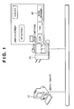
FIG. 1 is a conceptual system diagram of a document distribution system according to a first exemplary embodiment of the present invention. -
FIG. 2 is a hardware configuration diagram of a PC in the document distribution system according to the first exemplary embodiment of the present invention. -
FIG. 3 is a hardware configuration diagram of a digital multifunction peripheral in the document distribution system according to the first exemplary embodiment of the present invention. -
FIG. 4 is a software configuration diagram showing an example of the document distribution system according to the first exemplary embodiment of the present invention. -
FIG. 5 shows an exemplary user interface of a client application in the document distribution system according to the first exemplary embodiment of the present invention. -
FIG. 6 is a flow chart showing the outline of a procedure in the process of registering a scan and transmit button in the document distribution system according to the first exemplary embodiment of the present invention. -
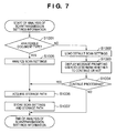
FIG. 7 is a flow chart showing a procedure in the process of analyzing scan and transmission settings information in the document distribution system according to the first exemplary embodiment of the present invention. -
FIG. 8 is a flow chart showing a procedure in the process of registering a scan and transmit button with a digital multifunction peripheral in the document distribution system according to the first exemplary embodiment of the present invention. -
FIG. 9 shows an exemplary user interface displayed in an operation unit of a digital multifunction peripheral in the document distribution system according to the first exemplary embodiment of the present invention. -
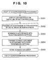
FIG. 10 is a flow chart showing a procedure for scan and transmission processing in the document distribution system according to the first exemplary embodiment of the present invention. -
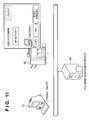
FIG. 11 is a conceptual system diagram of a document distribution system according to a second exemplary embodiment of the present invention. -
FIG. 12 is a software configuration diagram showing an example of the document distribution system according to the second exemplary embodiment of the present invention. -
FIG. 13 is a flow chart showing the outline of a procedure in the process of registering a scan and transmit button in the document distribution system according to the second exemplary embodiment of the present invention. -
FIG. 14 shows an exemplary user operation for associating a document icon and a digital multifunction peripheral icon with each other by a drag-and-drop operation, using a client application in a document distribution system according to a third exemplary embodiment of the present invention. -
FIG. 15 is a flow chart showing a procedure in the process of registering a scan and transmit button with a digital multifunction peripheral in a document distribution system according to a fourth exemplary embodiment of the present invention. - Hereinafter, preferable embodiments of the present invention will be described with reference to the drawings. First, a first exemplary embodiment of the present invention is described with reference to
FIGS. 1 to 10 . -
FIG. 1 is a conceptual system diagram of a document distribution system according to an exemplary embodiment of the present invention. In the document distribution system according to the present exemplary embodiment, aclient computer 10 having installed therein a client application exclusive to the document distribution system of the present exemplary embodiment and a digital multifunction peripheral 20 having copy, print, scanner, and FAX functions are connected through a network. Although not shown, in addition to theclient computer 10, other computers that can be a destination to which documents are distributed are also connected to the network. A user A accesses the document distribution system via a client application performed by theclient computer 10. Here, the document distribution system according to the present exemplary embodiment is configured to be accessed by the user A via a special-purpose client application; however, the configuration may be such that a general-purpose application, e.g., a browser, is installed on theclient computer 10 and is operated by a user. The digital multifunction peripheral 20 allows a scan and transmitbutton 40 to be preset and registered remotely. Such a presetting and registration operation can be remotely performed through communication with, for example, a computer. The document distribution system according to the present exemplary embodiment will be described in the case of using the digital multifunction peripheral 20 as an image forming apparatus. It may also use any other image forming apparatus such as a consumer scanner or the like. Furthermore, the document distribution system according to the present exemplary embodiment may be configured to be implemented on a Web application server not shown and to communicate with a browser. -
FIG. 2 is a hardware configuration diagram of each computer (PC) constituting the document distribution system according to the exemplary embodiment of the present invention. The hardware configuration diagram shown inFIG. 2 is considered to be equivalent to a hardware configuration diagram of a general information processing apparatus, so that the hardware configuration of a general information processing apparatus is applicable to each PC of the present exemplary embodiment. - In
FIG. 2 , aCPU 100 performs a program, such as an OS, an application, or the like, that has been stored in a program ROM of aROM 102 or that has been loaded from ahard disk 109 to aRAM 101. The term "OS" as used herein is an abbreviation for an operating system that is running on a computer, and such an operating system is hereinafter referred to as an "OS." The processing shown in the flow charts described later is implemented by execution of this program performed by theCPU 100. TheRAM 101 serves as a main memory, a work area, or the like of theCPU 100. Akeyboard controller 103 controls key input from akeyboard 107 or a pointing device not shown. Adisplay controller 104 controls display on a variety ofdisplays 108. Adisk controller 105 controls data access to or from a disk such as a hard disk (HD) 109, a flexible disk (FD), or the like that stores a variety of data. A network controller (NC) 106 is connected to the network and performs communication control processing for controlling communications with other equipment connected to the network. -
FIG. 3 shows the hierarchical configuration of a digital multifunction peripheral according to the exemplary embodiment of the present invention. InFIG. 3 , an image-formingunit 200 performs a series of image forming processes, such as paper handling, image transfer and fixing (duplicating), and the like, and forms an image on a recording medium such as recording paper. This image-formingunit 200 includes, for example, an inkjet printer or an electrophotographic image-forming device. An image-reading unit 201 including a scanner or the like optically reads an original image and converts the image into digital image information. The obtained digital image information may be input into the image-formingunit 200 so as to form an image, or may be passed to other units such as aFAX unit 203 or anetwork interface unit 206 and transmitted to other apparatuses through a line. - A digital multifunction
peripheral control unit 202 controls the operations of the image-formingunit 200 and the image-reading unit 201, for example, in such a manner that original information read by the image-reading unit 201 is duplicated by the image-formingunit 200. The digital multifunctionperipheral control unit 202 includes thenetwork interface unit 206, aprint control unit 205, theFAX unit 203, and an operation-unit control unit 204, and controls even the exchange of information between those units. TheFAX unit 203 can perform processing such as transmitting and receiving a facsimile image, i.e., transmitting digital image information read by the image-reading unit 201 or decoding the received facsimile signal and recording the decoded signal in the image-formingunit 200. Under the control of the operation-unit control unit 204, a signal is generated in accordance with a user operation using a control panel of an operation unit, a variety of data or messages are displayed on a display unit or the like of the operation unit. Under the control of theprint control unit 205, for example, print data received via thenetwork interface unit 206 is processed and output to and printed by the image-formingunit 200 for printing. Thenetwork interface unit 206 controls data transmission and reception between the apparatus and other communication terminals through communication lines. - An external
memory control unit 207 is capable of storing, in an external memory (not shown), image data that has been read by the image-reading unit 201 and converted to a data format storable in the external memory by the image-formingunit 200. The externalmemory control unit 207 is also capable of reading out data stored in an external memory, performing print processing via theimage forming unit 200, transmitting data to an external device via the network through thenetwork interface unit 206, and the like. - An
application manager 208 manages applications such as copying, scanning, and the like. Theapplication manager 208 controls each application by accepting activation, termination, installation, and uninstallation of each application or receiving equipment information generated by the digital multifunction peripheral control unit. -
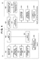
FIG. 4 is a software configuration diagram showing an example of the document distribution system according to the exemplary embodiment of the present invention. It shows the software configurations of theclient computer 10 and the digital multifunction peripheral 20. - First, the software configuration diagram of the
client computer 10 is described. Amain control unit 300 controls a client application in the document distribution system according to the exemplary embodiment of the present invention, and instructs and manages each unit described later. Aninformation display unit 301 displays, in accordance with an instruction from themain control unit 300, a user interface of the client application on theclient computer 10. An operationinformation acquisition unit 302 acquires information manipulated by a user via the user interface of the client application displayed by theinformation display unit 301 and notifies themain control unit 300 of the acquired information. A scansettings determination unit 303 determines scan settings for use as scan and transmission information from the document selected by a user. A storagelocation determination unit 304 determines a storage location for use as scan and transmission information according to repository information displayed in, for example, a tree view by theinformation display unit 301. A determinationresult storage unit 305 stores the scan settings determined by the scansettings determination unit 303 and storage location information indicating the storage location determined by the storagelocation determination unit 304. Adata reception unit 306 receives document data scanned by and transmitted from the digital multifunction peripheral 20 and notifies themain control unit 300 of the received document data. -
FIG. 5 shows an exemplary user interface (UI) of the client application displayed by theinformation display unit 301. The UI is configured to have anarea 501 for displaying repository information such as a tree view, adocument listing area 502 for displayingdocument data 504 as a thumbnail or an icon, and aperipherals listing area 503 for displaying information about peripherals such as digital multifunction peripherals. A user registers a scan and transmit button with the digital multifunction peripheral 20 by operating the user interface of the client application. Note that the form and area configuration of the user interface of the client application shown inFIG. 5 and a control method therefor are not limited to the example described above, and the user interface may be in any form as long as necessary functions can be implemented. For example, thedocument listing area 502 and theperipherals listing area 503 may display, instead of thumbnails or icons, a listing of filenames for specifying documents or peripherals, or a listing of character strings such as device names. - Next, the software configuration diagram of the digital multifunction peripheral 20 is described with reference to
FIG. 4 . Arequest reception unit 400 receives, in accordance with a user instruction, a request to register a scan and transmit button from themain control unit 300 of theclient computer 10 and notifies themain control unit 300 of the result of processing performed in response to the registration request. An operationbutton management unit 401 registers the scan and transmit button with an operationbutton storage unit 402 or extracts and edits information about the scan and transmit button. The operationbutton storage unit 402 stores information about scan and transmit buttons. Afunction execution unit 403 controls execution of the functions of the digital multifunction peripheral 20 in the document distribution system according to the exemplary embodiment of the present invention and instructs and manages each unit described. Aninformation display unit 404 displays, in accordance with an instruction from thefunction execution unit 403, a user interface in the operation unit of the digital multifunction peripheral 20. An operationinformation acquisition unit 405 acquires information manipulated by a user via the user interface of the digital multifunction peripheral 20 displayed by theinformation display unit 404 and notifies thefunction execution unit 403 of the acquired information. Adata transmission unit 406 transmits, to thedata reception unit 306 of theclient computer 10, document data scanned by the digital multifunction peripheral 20 in accordance with a user instruction. - Hereinafter, the processing in each step in the document distribution system according to the first exemplary embodiment of the present invention is described in detail with reference to
FIGS. 6 to 10 . Scan/Transmit Button Registration Processing - A user A can register a scan and transmit button with the digital multifunction peripheral 20 via the client application installed on the
client computer 10 in the document distribution system according to the exemplary embodiment of the present invention.FIG. 6 is a flow chart showing the outline of a procedure for scan/transmit button registration processing. The procedure is described below with reference toFIGS. 1 to 6 . The steps in the procedure shown inFIG. 6 , except step S105, are performed by theclient computer 10. Step S105 is performed by the digital multifunction peripheral 20 that has received scan and transmission settings information. - The client application in the document distribution system according to the exemplary embodiment of the present invention is activated upon a user instruction. Upon activation, in step S101, the
main control unit 300 instructs theinformation display unit 301 to display the user interface of the client application on thedisplay 108 of theclient computer 10. At this time, themain control unit 300 displays, in thedocument listing area 502, document data pieces in the folder selected by the user from thearea 501 for displaying repository information in, for example, a tree view. Also, themain control unit 300 acquires information about peripherals, such as the digital multifunction peripheral 20, that are operable by the client application, and displays the acquired information in theperipherals listing area 503. - Then, in step S102, a user operation for selecting and associating a
document data piece 504 and a digital multifunction peripheral 505 is accepted via the user interface displayed on thedisplay 108 in step S101. Upon accepting the selection and association operation, theinformation acquisition unit 302 transmits, to themain control unit 300, a notification indicating which document data and digital multifunction peripheral were selected and that association processing will be performed. Note that the term "association" as used herein refers to linking target data pieces to each other in order to make them identifiable; it can be implemented, for example, by adding information for identifying an associated data piece to data or by arranging data pieces in such a form that makes them identifiable. - Then, in step S103, upon accepting the user instruction to perform an association operation in step S102, the
main control unit 300 instructs the scansettings determination unit 303 and the storagelocation determination unit 304 to analyze scan settings and storage location information indicating storage locations. Note that the scan settings and the storage location information indicating storage locations are hereinafter collectively referred to as "scan and transmission settings information." The scansettings determination unit 303 and the storagelocation determination unit 304 respectively store the determination results, namely the scan settings and the storage location information indicating storage locations, in the determinationresult storage unit 305. - Then, in step S104, upon acquiring the scan and transmission settings information analyzed in step S103 from the determination
result storage unit 305, themain control unit 300 transmits the acquired scan and transmission settings information to therequest reception unit 400 of the digital multifunction peripheral 20 and requests the registration of a scan and transmit button. - Then, in step S105, upon receiving the request to register a scan and transmit button in step S104, the
request reception unit 400 of the digital multifunction peripheral 20 instructs the operationbutton management unit 401 to store the scan and transmit button in the operationbutton storage unit 402. Therequest reception unit 400 also notifies themain control unit 300 of theclient computer 10 of the result of storage in the operationbutton storage unit 402. - In step S106, upon receiving the result of registration of the scan and transmit button notified by the
request reception unit 400 in step S105, themain control unit 300 instructs theinformation display unit 301 to display the received registration result on thedisplay 108 so as to notify the user A. - When a user performs an operation for associating
document data piece 504 and a digital multifunction peripheral 505 via the UI in step S102, the analysis of the scan and transmission settings information is performed in step S103.FIG. 7 is a flow chart showing a procedure in the process of analyzing the scan and transmission settings information in step S103. The detail of the procedure is described below with reference toFIGS. 4 and7 . - In step S1001, upon receiving a user instruction to perform an association operation in step S102, the
main control unit 300 instructs the scansettings determination unit 303 to determine whether the actual document corresponding to thedocument data piece 504 is of an analyzable document type or not. More specifically, in the case where analyzable file formats (e.g., TIFF, JPEG, PDF, etc.) have been set previously, the scansettings determination unit 303 may make the determination according to the extension of the document data piece. Alternatively, the scansettings determination unit 303 may determine whether the document data piece is analyzable or not by expanding the document data piece into a memory and then analyzing the header information of the document data piece, or may use any other method. - Then, when the data piece is determined as being of a document type that cannot be analyzed in step S1001, then in step S1002, the
main control unit 300 loads default scan settings that have previously been stored in the determinationresult storage unit 305. Here, the default scan settings may be acquired from the digital multifunction peripheral 20 specified by the user association operation in step S102. In any case, the above example is not intended to limit the method of acquiring the default scan settings. - Then, in step S1003, the
main control unit 300 instructs theinformation display unit 301 to display the determination result in step S1001 and the default scan settings acquired in step S1002 on thedisplay 108 of theclient computer 10. The default scan settings include settings such as scan resolution, color mode, original size, file format, and the like. Then, themain control unit 300 prompts the user to enter whether to continue the processing or not in step S1004, accepts the user input in response to the prompt, and judges the input value. - When it has been determined in step S1001 that the data piece is of an analyzable document type, then in step S1005, the scan
settings determination unit 303 extracts information for use as scan settings from the document data. Specifically, the scansettings determination unit 303 analyzes settings included in the document data, such as resolution, color mode, original size, file format, and the like. As a result of the analysis, in step S1007, settings information included in the document data and determined as being scan settings is stored as scan settings in the determinationresult storage unit 305. Furthermore, if the document data piece is in PDF format, more detailed scan settings can be obtained by determining the presence or absence of settings such as page rotation information, OCR text embedding, encryption, and the like and, if such settings are present, by fetching those settings into the scan settings. Note that the information analyzed as the scan settings is not limited to the information described above; it is also possible, according to the document type of the document data piece, to analyze any other information that can be used as scan settings. In this way, the scan settings are extracted using the selected document data piece as model data. - Following step S1005 (or S1002, S103 and S1004), in step S1006, upon receiving the user instruction to perform an association operation in step S102, the
main control unit 300 instructs the storagelocation determination unit 304 to acquire a path to the location where the document data corresponding to thedocument data piece 504 has been stored. Here, the document data may be stored in theexternal memory 109 of theclient computer 10. Or, the document data may be stored in a shared folder on a file server (not shown) connected to theclient computer 10 through the network. When the document data is stored in theexternal memory 109 of theclient computer 10, the path to the location where the document data piece has been stored is a path including a host name on the network of theclient computer 10. Also, when the document is stored in a shared folder on a file server, the path to the location where the document data piece has been stored is a network path of the shared folder. In any case, the locations of document data pieces are identifiable by theclient computer 10. Note that, in the case where the path to the location where the document data piece has been stored can be neither directly referred to nor read or written by the digital multifunction peripheral 20, the scanned document may be exchanged between theclient computer 10 and the digital multifunction peripheral 20 via a protocol such as FTP. Here, the "scanned document" refers to document data obtained by scanning an original such as paper; it may be image data, or character-recognized text data, or document data obtained by formatting such text data. In that case, a monitor program not shown may be activated and the scanned document may automatically be shifted to the location where the document data piece has been stored. Moreover, in the case where authentication information is necessary during these process steps, user information may also be acquired as a single piece of information about a storage path. - Then, in step S1007, the
main control unit 300 stores the scan settings analyzed in step S1002 or S1005 (as mentioned above) and the storage path, i.e., the location information, acquired in step S1006 in the determinationresult storage unit 305. - When, in step S104, a request to register a scan and transmit button has been issued from the client application installed on the
client computer 10 in the document distribution system according to the exemplary embodiment of the present invention, the scan and transmit button is registered with the digital multifunction peripheral 20. Upon receiving the request, the digital multifunction peripheral 20 performs the registration of the scan and transmit button in step S105.FIG. 8 is a flow chart showing a procedure in the process of registering a scan and transmit button with the digital multifunction peripheral 20 (step S105). The detail of the procedure shown is described with reference toFIGS. 4 and8 . The procedure shown inFIG. 8 is performed by the digital multifunction peripheral 20. - In step S1101, the
request reception unit 400 determines whether or not the request received from the client application of theclient computer 10 in step S104 is a request to register a scan and transmit button. If the procedure shown inFIG. 8 is performed upon a request to register a scan and transmit button, step S1101 can be omitted. Note that the loop shown for the case where the request is determined as not being a request to register a scan and transmit button in step S1101 is just for convenience in the drawing and, in practice, any appropriate processing shall be performed before going into a standby mode for the next request. - Then, in step S1102, the operation
button management unit 401 analyzes the request to register a scan and transmit button, received by therequest reception unit 400. In step S1103, it is determined, according to the result in step S1102, whether or not the contents of the request to register a scan and transmit button, i.e., the received scan settings, can be registered without any modifications with the digital multifunction peripheral 20. If any setting item that cannot be registered or any setting item that should be added is present, that setting item is specified. For example, in the case where the scan and transmit button has color settings but the digital multifunction peripheral 20 can scan only in monochrome, the settings for the scan and transmit button need to be modified. Also, not all scan and transmit buttons include all scan settings necessary to perform scanning with the digital multifunction peripheral 20. - Then, when it has been determined in step S1103 that the scan and transmit button of the registration request cannot be registered as-is, then in step S1104, the operation
button management unit 401 loads the default scan and transmit button settings stored in the operationbutton storage unit 402. - Then, in step S1105, using the default scan and transmit button settings acquired in step S1104, the settings for the scan and transmit button specified by the registration request from the
client computer 10 are modified, or another setting item is added to those settings. Here, modification or addition is necessary only for such a setting item that has been determined as being difficult to be set as-is with the digital multifunction peripheral 20 or whose addition has been determined as being necessary; thus, as to the other items that have been determined as being capable of being set as-is, the received scan settings are used as-is. - Then, in step S1106, the operation
button management unit 401 stores the scan and transmit button and its relevant scan and transmission settings information (i.e., the scan settings and the storage location) in the operationbutton storage unit 402. By doing so, a new scan and transmit button is registered with the digital multifunction peripheral 20. The operationbutton management unit 401 also notifies therequest reception unit 400 of the registration result. Here, the registration of a scan and transmit button may be performed for each user, or may be performed for each group so as to allow users in the group to share the button, or may be performed so as to allow all users to share the button. On this account, user information for specifying the range of users allowed to use a button is added to scan and transmission settings information associated with each scan and transmit button. Then, when a user logs in to the digital multifunction peripheral 20, the user information about a scan and transmit button is referred to, and the scan and transmit button is displayed in the user interface only for a user who is allowed to use the button. - Then, in step S1107, the
request reception unit 400 notifies themain control unit 300 of theclient computer 10 of the result of the registration of the scan and transmit button obtained in step S1006. The registration result may indicate for example only whether the registration of a scan and transmit button in response to the registration request has succeeded or not; however, in consideration of the possibility that the settings may be modified or added, the registration result should preferably include the scan settings that have been actually registered with the digital multifunction peripheral 20. -
FIG. 9 shows an exemplary user interface displayed in the operation unit of the digital multifunction peripheral 20 in the document distribution system according to the exemplary embodiment of the present invention. When a user logs in to the digital multifunction peripheral 20, the operation unit of the digital multifunction peripheral 20 displays alocal UI 601 and a registered scan and transmitbutton 602. Here, as previously described, only a scan and transmit button available for use by the logged-in user is displayed. Note that the form and configuration of the exemplary user interface shown inFIG. 9 and a control method therefor are not limited to the example described withFIG. 9 . A browser not shown may operate in the operation unit of the digital multifunction peripheral 20 and the user interface may be generated by HTML. - Upon an operation by a user A such as touching the
button 602 or the like, the digital multifunction peripheral 20 performs scanning and transmission. The client application in the document distribution system, which has been installed on theclient computer 10 where the folder specified as a storage location of scan data (referred to as scanned document data) is present, receives and acquires document data from the digital multifunction peripheral 20.FIG. 10 is a flow chart showing a procedure for scan and transmission processing. The procedure is described below with reference toFIGS. 4 and10 . Steps S201 to S204 shown inFIG. 10 are performed by the digital multifunction peripheral 20. Step S205 is performed by a client computer to which document data is distributed, such as theclient computer 10. - In step S201, when a user logs in to a digital multifunction peripheral 20 in a document distribution system, the
function execution unit 403 acquires scan settings information stored in the operationbutton storage unit 402 via the operationbutton management unit 401. Of course, the information to be acquired is limited to the one available for use to the logged-in user. Thefunction execution unit 403 instructs theinformation display unit 404 to display a user interface in which the scan and transmit button associated with the acquired scan settings information is located, in the operation unit of the digital multifunction peripheral 20. - Then, in step S202, the pressing of the scan and transmit button by the user is accepted via the user interface displayed on the digital multifunction peripheral 20 in step S201. The operation
information acquisition unit 405 transmits a notification indicating that the scan and transmit button has been pressed, to thefunction execution unit 403. - Then, in step S203, upon accepting the pressing of the scan and transmit button by the user in step S202, the
function execution unit 403 acquires the scan settings from the settings information corresponding to the pressed scan and transmit button. There is also the case where a plurality of scan and transmit buttons are present; therefore, the settings corresponding to the pressed button, from among the scan and transmit buttons stored in the operationbutton storage unit 402 via the operationbutton management unit 401, are searched for and acquired. In accordance with the acquired scan and transmit button settings information, thefunction execution unit 403 reads a paper original not shown via the image reading unit of the digital multifunction peripheral 20 so as to acquire scanned document data. - Then, in step S204, the
function execution unit 403 instructs thedata transmission unit 406 to transmit the scanned document data obtained in step S203 to the destination, namely, the storage location included in the settings information associated with the scan and transmit button. - Then, in step S205, the
data reception unit 306 of theclient computer 10 receives the scanned document data transmitted by the digital multifunction peripheral 20 in step S204. Theclient computer 10 stores the received scanned document data in a specified storage location (storage path). Here, as previously described, in the case where the specified storage path can be neither directly referred to nor read or written by the digital multifunction peripheral 20, the digital multifunction peripheral 20 may transmit the scanned document via a protocol, not shown, such as FTP. In that case, a monitor program not shown may be activated and the scanned document may automatically be shifted to the specified storage path. - As described above, the scan settings are acquired according to the attributes of existing document data, and the scan and transmission settings information using the acquired scan settings as its scan settings and the storage location of that document data as a destination, to which scanned and transmitted data is transmitted, is transmitted to a scanner device such as a digital multifunction peripheral. Upon receipt of the settings information, the scanner device displays, in the user interface, a newly operable operation button corresponding to the received scan settings information.
- A second exemplary embodiment of the present invention is described with reference to
FIGS. 11 to 13 . What makes the second exemplary embodiment different from the document distribution system of the first exemplary embodiment is that documents stored in adocument management service 30 are browsed by operating the client application installed on theclient computer 10 in the document distribution system according to the present exemplary embodiment. Furthermore, thedocument management service 30 can store document data scanned by and transmitted from the digital multifunction peripheral 20. Here, thedocument management service 30 stores documents in association with scan and transmission settings information for registering scan and transmitbuttons 40 with the digital multifunction peripheral 20. This enables the client application to acquire the scan and transmission settings information from thedocument management service 30. -
FIG. 11 is a conceptual system diagram of a document distribution system according to the second exemplary embodiment of the present invention. Theclient computer 10 has installed therein a client application specifically designed for a user A to access the document distribution system according to the present exemplary embodiment. The document distribution system is constituted by thisclient computer 10, the digital multifunction peripheral 20 having copy, print, scanner, and FAX functions, and thedocument management service 30 that stores and manages documents, all of which are connected through a network. Thedocument management service 30 is made available by a server implemented by a computer. - While in the configuration of the present exemplary embodiment, the
client computer 10 and thedocument management service 30 are separate computers, though they may be constituted by a single PC. Furthermore, while the document distribution system according to the present exemplary embodiment is configured to be accessed by a user A via the special-purpose client application, the configuration may be such that a browser not shown is installed and run on theclient computer 10, in which case the configuration may be such that the document distribution system according to the present exemplary embodiment is implemented on a Web application server not shown and communicates with the browser. -
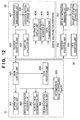
FIG. 12 is a software configuration diagram showing an example of the document distribution system according to the exemplary embodiment of the present invention. It shows the software configurations of theclient computer 10, the digital multifunction peripheral 20, and thedocument management service 30. This system differs from the document distribution system of the first exemplary embodiment in that the software configuration of thedocument management service 30 is added. This system also differs in that, in order to acquire a document data piece as model data for scan settings from thedocument management service 30, thedocument management service 30 becomes a destination to which the scanned document data is transmitted from thedata transmission unit 406 of the digital multifunction peripheral 20. Of course, even in the configuration shown inFIG. 12 , if a document data piece stored in theclient computer 10 itself is used as model document data, theclient computer 10 becomes a destination to which data is transmitted. Below, only the software configuration of thedocument management service 30 is described. - Upon a user instruction, a
request reception unit 700 receives a request to, for example, acquire folder information or document data from themain control unit 300 of theclient computer 10, and notifies the main control unit.300 of the processing result for each request. A documentinformation management unit 701 registers document data with a documentinformation storage unit 702 or extracts and edits a folder and document data. The documentinformation storage unit 702 stores document data. Adata reception unit 703 receives the document data scanned by and transmitted from the digital multifunction peripheral 20 and notifies the documentinformation management unit 701 to store the received data in the documentinformation storage unit 702. - Here, when storing the document data scanned by and transmitted from the digital multifunction peripheral 20 in the document
information storage unit 702, the operation performed by the digital multifunction peripheral 20 is stored in association with the document data. By doing so, scan and transmission settings information set by using this document data as model data can be reused in later steps. Note that the operation performed by the digital multifunction peripheral 20 includes scan setting, the setting of communication means with thedocument management service 30, and the like; it may also include any other information (such as a workflow) that can be used as scan and transmission settings information. - Moreover, the above example is not intended to limit the method of associating the document data stored in the document
information storage unit 702 and the scan and transmission settings information. The scan and transmission settings information may be stored on a DB (database) table relative to document data, or may be stored in a file such as XML or the like, in which case a path to the file may be stored as the attributes of document data. The detail of the processing in each step in the document distribution system according to the second exemplary embodiment of the present invention is described below with reference toFIGS. 5 and11 to 13 . - A user A registers a scan and transmit button with the digital multifunction peripheral 20 via a client application of the
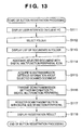
client computer 10 in the document distribution system according to the exemplary embodiment of the present invention.FIG. 13 is a flow chart showing the outline of a procedure for scan/transmit button registration processing. The procedure is described below with reference toFIGS. 5 and11 to 13 . - The client application is activated in accordance with a user instruction. Upon activation, in step S111, the
main control unit 300 instructs theinformation display unit 301 to display the user interface of the client application on thedisplay 108 of theclient computer 10. - Then, in step S112, the
information acquisition unit 302 accepts a user operation for selecting a folder within thedocument management service 30 via the user interface displayed on thedisplay 108 in step S111. Theinformation acquisition unit 302 transmits, to themain control unit 300, information indicating that the folder selection operation has been accepted. Here, the "folder selection operation" is, for example, the selection of a folder of thedocument management service 30 displayed in thearea 501 for displaying repository information such as a tree view. Or, a desired folder that has been found by inputting search conditions not shown, or a folder of thedocument management service 30 containing documents may be selected. - Then, in step S113, upon accepting the user instruction to perform a folder selection operation in step S112, the
main control unit 300 transmits information for specifying the folder to therequest reception unit 700 of the document management service. Therequest reception unit 700 instructs the documentinformation management unit 701 to acquire a listing of documents in the folder from the documentinformation storage unit 702, using the information specifying the folder that was transmitted from themain control unit 300. Therequest reception unit 700 then notifies themain control unit 300 of the acquired document listing. Themain control unit 300 instructs theinformation display unit 301 to display, on thedisplay 108, the document listing information notified by therequest reception unit 700. More specifically, a listing of documents stored in the folder of thedocument management service 30 is displayed in thedocument listing area 502 for displaying documents in the form of thumbnails or icons. Through the user interface displayed on thedisplay 108 in step S113, the user can select and associate a document data piece and a digital multifunction peripheral, i.e., the user can establish association therebetween. - Then, in step S114, upon accepting the user operation for associating a
document data piece 504 and a digital multifunction peripheral 505, theinformation acquisition unit 302 transmits that information to themain control unit 300. - Then, in step S115, upon accepting the user instruction to perform an association operation in step S114, the
main control unit 300 transmits information for specifying the selected document data, to therequest reception unit 700 of thedocument management service 30. Therequest reception unit 700 instructs the documentinformation management unit 701 to acquire the scan and transmission settings information stored in the documentinformation storage unit 702 in association with the selected document data, and notifies themain control unit 300 of the acquired information. Target scan and transmission settings information can be specified by using the information specifying the document data that was transmitted from themain control unit 300 as part of step S115. - Then, in step S116, upon acquiring the scan and transmission settings information in step S115, the
main control unit 300 transmits a registration request as well as the scan and transmission settings information to therequest reception unit 400 of the digital multifunction peripheral 20. Thereby, a request to register the scan and transmit button is issued. - Then, in step S117, upon receiving the scan/transmit button registration request in step S116, the
request reception unit 400 of the digital multifunction peripheral 20 instructs the operationbutton management unit 401 to store the scan and transmission settings information in the operationbutton storage unit 402. - Then, in step S118, the
request reception unit 400 notifies themain control unit 300 of theclient computer 10 of the result of the storage in the operationbutton storage unit 402 in step S117. Themain control unit 300 instructs theinformation display unit 301 to display the scan/transmit button registration result notified by therequest reception unit 400 on thedisplay 108, in order to notify the user A. - Note that while, in step S113, a listing of documents in the
document management service 30 is displayed upon receipt of a user instruction to perform a folder selection operation in step S112, a listing of documents that had previously been in the folder may be displayed. This allows scan and transmission settings information to be acquired and a scan and transmit button to be registered with the digital multifunction peripheral 20, using those documents that had previously been in the selected folder but are currently in the other folder(s). - As to scan and transmission processing, what makes the present exemplary embodiment different from the document distribution system of the first exemplary embodiment is that the destination to which scanned documents are distributed from the digital multifunction peripheral 20 is the
document management service 30 rather than theclient PC 10. A user A performs scanning and transmission via the digital multifunction peripheral 20, and acquires documents from and stores documents in thedocument management service 30 in the document distribution system according to the exemplary embodiment of the present invention. Below, only steps that are different from the first exemplary embodiment are described with reference toFIG. 10 . - In step S204, the
function execution unit 403 of the digital multifunction peripheral 20 instructs thedata transmission unit 406 to transmit the scanned document data obtained in step S203 to the storage path specified by the scan and transmit button. - Then, in step S205, the
data reception unit 703 of thedocument management service 30 receives the scanned document data transmitted by the digital multifunction peripheral 20 in step S204 and stores the received data in the specified storage path. Here, as previously described, there is a case where the path in which the document data has been stored can be neither directly referred to nor read or written to by the digital multifunction peripheral 20. In that case, the digital multifunction peripheral 20 may transmit the scanned document via a protocol, not shown, such as FTP, a Web service, or the like. In this case, a monitor program not shown may be activated and the scanned document may automatically be shifted to the specified storage path. - As described above, according to the second exemplary embodiment of the present invention, the use of documents stored in the document management service and scan and transmission settings information associated with the documents allows a user to reuse accurate settings in which scanning and transmission have been performed with a digital multifunction peripheral.
- A third exemplary embodiment of the present invention is described with reference to
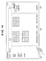
FIGS. 6 ,13 , and14 . What makes the third exemplary embodiment different from the document distribution systems according to the first and second exemplary embodiments is a user interface. A user associates adocument icon 510 and a digital multifunctionperipheral icon 511 with each other through a drag-and-drop operation, by operating the client application on theclient computer 10 in the document distribution system of the present invention. This association operation enables a scan and transmit button to be registered with the digital multifunction peripheral 20. The detail of the processing in each step in the document distribution system according to the third exemplary embodiment of the present invention is described below with reference toFIG. 6 , which shows the scan/transmit button registration processing according to the first exemplary embodiment,FIG. 13 , which shows the scan/transmit button registration processing according to the second exemplary embodiment, andFIG. 14 , which shows an exemplary user interface according to the present exemplary embodiment. - A user A registers a scan and transmit button with the digital multifunction peripheral 20 via the client application of the
client computer 10 in the document distribution system according to the exemplary embodiment of the present invention.FIG. 6 shows the scan/transmit button registration processing performed in the document distribution system according to the first exemplary embodiment, andFIG. 13 shows the scan/transmit button registration processing performed in the document distribution system according to the second exemplary embodiment. Below, only different steps are described with reference toFIGS. 6 and13 . Note that the reference numerals used inFIG. 13 are shown within parentheses. - This procedure starts upon activation of the client application of the document distribution system according to the present exemplary embodiment in accordance with a user instruction. First, in step S101, the
main control unit 300 instructs theinformation display unit 301 to display the user interface of the client application on thedisplay 108 of theclient computer 10. - At this time, the
main control unit 300 displays, in thedocument listing area 502 in the form of icons such as adocument icon 510, a listing of document data pieces in the folder selected by a user from thearea 501 for displaying repository information in, for example, a tree view. Here, the icons may be thumbnails of the document data pieces or may be formed into a preview display, etc. - The
main control unit 300 also acquires information about peripherals, such as the digital multifunction peripheral 20, that are operable by the client application, and displays the peripherals in the peripherals listing area in the form of icons, such as a digital multifunctionperipheral icon 511. - In step S102(S114), the user drags and drops a
document icon 510 onto a digital multifunctionperipheral icon 511 via the user interface displayed on thedisplay 108 in step S101 (S113). Upon accepting the user operation for associating thedocument icon 510 and the digital multifunctionperipheral icon 511 by a drag-and-drop operation, theinformation acquisition unit 302 transmits information regarding the association to themain control unit 300. Of course, a digital multifunctionperipheral icon 511 may alternatively be dragged onto adocument icon 510 in order to establish an association therebetween. -
FIG. 14 shows an exemplary user operation for associating a document icon and a digital multifunction peripheral icon by a drag-and-drop operation. Note that as to the user interface of the client application shown inFIG. 14 and its operability, the form and configuration thereof and a control method therefor are not limited to the example described above, and they may be in any form as long as necessary functions can be implemented. - According to the third exemplary embodiment of the present invention, by performing an intuitive operation, i.e., the dragging and dropping of a document icon onto a digital multifunction peripheral icon or vice versa, a user can omit an operation step and can create scan and transmission settings information and register a scan and transmit button with a digital multifunction peripheral.
- A fourth exemplary embodiment of the present invention is described with reference to
FIGS. 4 ,12 , andFIG. 15 . What makes the fourth exemplary embodiment different from the document distribution systems according to the first, second, and third exemplary embodiments is that, if a scan and transmit button having the same settings is already present when attempting to register a scan and transmit button with the digital multifunction peripheral 20, only reference information about the scan and transmit button having the same settings is stored. This avoids duplicate registrations of a plurality of scan and transmit buttons having the same settings. This thus results in the effective use of resources of the digital multifunction peripheral 20. The detail of the processing in each step in the document distribution system according to the fourth exemplary embodiment of the present invention is described below with reference toFIG. 4 , which shows the configuration according to the first exemplary embodiment,FIG. 12 , which shows the configuration according to the second exemplary embodiment, andFIG. 15 , which shows scan/transmit button registration processing according to the present exemplary embodiment. - As to the processing for registering a scan and transmit button with a digital multifunction peripheral, what makes the fourth exemplary embodiment different from the document distribution systems according to the first, second, and third exemplary embodiments is the following. That is, the process of registering a scan and transmit button with the digital multifunction peripheral 20 includes the step of determining whether or not any scan and transmit button having the same settings is already present.
- In step S104, when a request to register a scan and transmit button is issued from the client application of the
client computer 10 in the document distribution system according to the exemplary embodiment of the present invention, the scan and transmit button is registered with the digital multifunction peripheral 20.FIG. 15 is a flow chart showing a procedure in the process of registering a scan and transmit button with the digital multifunction peripheral 20. Below, only different steps are described with reference toFIGS. 4 ,12 , and15 . - The processing from steps S1111 to S1115 shown in
FIG. 15 is identical to that from steps S1101 to S1105 shown inFIG. 8 , so the description of these steps are omitted in the present exemplary embodiment. - Then, in step S1116, the operation
button management unit 401 determines whether any already-registered scan and transmit button has the same settings as the scan and transmit button to be registered, by searching for the settings for the already-registered scan and transmit buttons stored in the operationbutton storage unit 402. The settings for each already-registered scan and transmit button consist of a pair of scan settings and a storage location. Here, whether the settings are the same or not may be determined by a comparison of all the settings, i.e., exact matching, or may be determined by a comparison of only the scan settings. However, this is not intended to limit the criteria used for determination. Furthermore, if any modification or addition of the contents of the scan settings is necessary, the modified or information-added scan settings are used for comparison and determination. - Then, when having determined in step S1116 that the scan and transmit button having the same settings had already been registered, then in step S1117, the operation
button management unit 401 extracts reference information for the scan and transmit button to be referred to, from the operationbutton storage unit 402. Here, the reference information for the scan and transmit button may be an ID for specifying the scan and transmit button to be referred to, or may be any other means. - Then, in step S1118, the operation
button management unit 401 stores, in the operationbutton storage unit 402, only reference information about a new scan and transmit button, or, if the same settings are already present, only reference information about the scan and transmit button to be referred to. In the latter case, the reference information to be stored is the information extracted in step S1117. Through this operation, a scan and transmit button is registered with the digital multifunction peripheral 20 and therequest reception unit 400 is notified of the registration result. Here, the registration of a scan and transmit button may be performed for each user, or may be performed for each group so as to allow users in the group to share the button, or may be performed so as to allow all users to share the button. - Then, in step S1119, the
request reception unit 400 notifies themain control unit 300 of theclient computer 10 of the scan/transmit button registration result obtained in step S1118. - According to the fourth exemplary embodiment of the present invention, if a scan and transmit button having the same settings is already present when registering a scan and transmit button with a digital multifunction peripheral, only reference information about the scan and transmit button having the same settings is stored in order to avoid duplicate registration. This enables the effective use of the resources of a digital multifunction peripheral without the user giving any consideration to the duplication of buttons.
- Note that the present invention may be applied to a system consisting of a plurality of apparatuses (such as a host computer, an interface device, a reader, a printer, and the like), or may be applied to an apparatus consisting of a single device (such as a copy machine, a facsimile machine, or the like). There may alternatively be provided a system or apparatus with a storage medium in which a program for achieving a function in an exemplary embodiment described above is stored and by the system or apparatus reading out and running the program stored in the storage medium. In this case, the program itself that is read out from the storage medium realizes the functionality of any embodiment described above, and the program itself and the storage medium in which the program is stored constitute the main features of the present invention.
- The present invention also includes the case where an OS or the like that is running on a computer can perform part or all of the actual processing based on instructions in the program, thereby realizing the functionality of the present invention. Furthermore, the present invention is also applicable to the case where the program read from the storage medium can be written to a memory provided in a function expansion board inserted in a computer or a function expansion unit connected to a computer. In this case, a CPU or the like provided in the function expansion board or the function expansion unit performs part or all of the actual processing based on instructions written in the program, thereby realizing the functionality of the present invention.
- While the present invention has been described with reference to exemplary embodiments, it is to be understood that the invention is not limited to the disclosed exemplary embodiments. The scope of the following claims is to be accorded the broadest interpretation so as to encompass all such modifications and equivalent structures and functions.
Claims (8)
- An information processing apparatus (10) for creating scan and transmission settings for an image input apparatus (20) with which scan and transmission settings can be registered, the information processing apparatus (10) comprising:association means (300) configured to associate existing document data (504) with an image input apparatus (20;505) for which scan and transmission settings are to be created, the existing document data (504) being data stored in a storage unit (10; 30) associated with the information processing apparatus (10);extraction means (303) configured to extract scan settings from the existing document data (504) associated with the image input apparatus (20; 505);setting means (304) configured to set a location in the storage unit where the existing document data (504) has been stored as a storage location to which scan data is to be transmitted by the image input apparatus (20) as a result of a scanning operation in the image input apparatus; andtransmission means (300) configured to transmit the extracted scan settings and the set storage location to the image input apparatus (20) as scan and transmission settings that are to be registered with the image input apparatus.
- The information processing apparatus (10) according to claim 1, wherein
the association means (300) is further configured to obtain the existing document data (504) from a document management apparatus (30) that is connected to the image input apparatus (20); and
the extraction means (303) is configured to extract scan settings from the document management apparatus (30) in which scan settings are stored in association with the existing document data (504). - A document distribution system in which an information processing apparatus (10) is arranged to create scan and transmission settings for an image input apparatus (20) with which scan and transmission settings can be registered, the document distribution system comprising:an information processing apparatus (10) according to claim 1 or 2, andan image input apparatus (20) comprising:user interface means (405);display means (404) configured to receive scan and transmission settings including scan settings and a storage location of scan data, and to display, using the user interface means (405), an operation unit (40) corresponding to the scan and transmission settings; andscan and transmission means (406), configured to, upon operation of the operation unit (40), scan a document according to the scan settings and store the scanned document as scan data in the storage location.
- A document distribution system according to claim 3, wherein the creation, by the information processing apparatus (10), of the scan and transmission settings is carried out remotely from the image input apparatus (20).
- A control method for an information processing apparatus (10) that is for creating scan and transmission settings for an image input apparatus (20) with which scan and transmission settings can be registered, the control method comprising:associating (S102; S114) existing document data (504) with an image input apparatus (20; 505) for which scan and transmission settings are to be created, the existing document data being data stored in a storage unit associated with the information processing apparatus (10);extracting (S1005) scan settings from the existing document data (504) associated with the image input apparatus (20; 505);setting (S1006) a location in the storage unit where the existing document data has been stored as a storage location to which scan data is transmitted as a result of a scanning operation in the image input apparatus (20; 505); andtransmitting (S104) the extracted scan settings and the set storage location to the image input apparatus (20) as scan and transmission settings that are to be registered with the image input apparatus (20; 505).
- A control method for a document distribution system in which an information processing apparatus (10) creates scan and transmission settings for an image input apparatus (20) with which scan and transmission settings can be registered, comprising
a control method for the information processing apparatus (10) according to claim 5; and the control method further includes, with respect to the image input apparatus:receiving (S1101) the scan and transmission settings including scan settings and a storage location of scan data and displaying (S201) an operation unit (40) corresponding to the scan and transmission settings using a user interface means (405); andscanning (S203), upon operation (S202) of the operation unit, a document according to the scan settings and storing (S205) the scanned document as scan data in the storage location. - Computer program code that, when executed by a computer, causes the computer to carry out a method according to claim 5 or 6.
- A computer-readable recording medium having stored thereon computer program code according to claim 7.
Applications Claiming Priority (1)
| Application Number | Priority Date | Filing Date | Title |
|---|---|---|---|
| JP2008181987A JP5199761B2 (en) | 2008-07-11 | 2008-07-11 | Information processing apparatus, image input apparatus, document distribution system, and control method therefor |
Publications (3)
| Publication Number | Publication Date |
|---|---|
| EP2144429A2 EP2144429A2 (en) | 2010-01-13 |
| EP2144429A3 EP2144429A3 (en) | 2010-08-04 |
| EP2144429B1 true EP2144429B1 (en) | 2012-06-06 |
Family
ID=41203640
Family Applications (1)
| Application Number | Title | Priority Date | Filing Date |
|---|---|---|---|
| EP09164439A Not-in-force EP2144429B1 (en) | 2008-07-11 | 2009-07-02 | Information processing apparatus, image input apparatus, document distribution system, and control method therefor |
Country Status (6)
| Country | Link |
|---|---|
| US (1) | US8610922B2 (en) |
| EP (1) | EP2144429B1 (en) |
| JP (1) | JP5199761B2 (en) |
| KR (1) | KR101088925B1 (en) |
| CN (1) | CN101626444B (en) |
| RU (1) | RU2425413C2 (en) |
Families Citing this family (25)
| Publication number | Priority date | Publication date | Assignee | Title |
|---|---|---|---|---|
| JP2009187131A (en) * | 2008-02-04 | 2009-08-20 | Canon Inc | Document management apparatus, document management method, and computer program |
| KR20110068550A (en) * | 2009-12-16 | 2011-06-22 | 삼성전자주식회사 | Image forming apparatus and method for providing local user interface thereof |
| JP5668376B2 (en) * | 2010-09-06 | 2015-02-12 | 株式会社リコー | Image forming system, server, image forming apparatus, and program |
| JP5725830B2 (en) * | 2010-12-15 | 2015-05-27 | キヤノン株式会社 | Information processing apparatus, control method thereof, and control program |
| JP5821325B2 (en) * | 2011-06-27 | 2015-11-24 | 富士ゼロックス株式会社 | Image forming system |
| JP5476340B2 (en) | 2011-06-28 | 2014-04-23 | 京セラドキュメントソリューションズ株式会社 | Image reading apparatus and image reading system |
| US8890672B2 (en) * | 2011-08-29 | 2014-11-18 | Harnischfeger Technologies, Inc. | Metal tooth detection and locating |
| JP5768649B2 (en) * | 2011-10-19 | 2015-08-26 | コニカミノルタ株式会社 | Image forming system, image forming apparatus, and control program |
| KR101286224B1 (en) * | 2011-10-25 | 2013-07-15 | 한국항공우주산업 주식회사 | A connecting method of requisition form for requesting distribution and derivering confirmation |
| US9473668B2 (en) * | 2011-11-01 | 2016-10-18 | Siemens Industry, Inc. | Distributed storage and processing of mail image data |
| JP5966368B2 (en) * | 2012-01-11 | 2016-08-10 | 株式会社リコー | Information processing apparatus, device management system, and program |
| JP6066572B2 (en) * | 2012-02-28 | 2017-01-25 | キヤノン株式会社 | Image processing apparatus, control method for image processing apparatus, and control program |
| JP5850001B2 (en) * | 2012-07-10 | 2016-02-03 | 株式会社リコー | System and method |
| JP6155899B2 (en) * | 2012-07-12 | 2017-07-05 | 株式会社リコー | Information processing system, information processing apparatus, device, information processing method, and program |
| JP6184269B2 (en) * | 2013-09-18 | 2017-08-23 | キヤノン株式会社 | Image processing system, information processing apparatus, image processing method, information processing method, and program |
| CN104580792B (en) * | 2013-10-14 | 2018-11-06 | 株式会社东芝 | The execution method of image forming apparatus, image forming apparatus |
| JP6446995B2 (en) * | 2013-10-29 | 2019-01-09 | 株式会社リコー | Information processing system and information processing method |
| JP6176174B2 (en) * | 2014-03-31 | 2017-08-09 | ブラザー工業株式会社 | Control program and information processing apparatus |
| JP6344960B2 (en) * | 2014-04-18 | 2018-06-20 | キヤノン株式会社 | Image processing apparatus, image processing apparatus control method, and program |
| JP2016115974A (en) * | 2014-12-11 | 2016-06-23 | キヤノン株式会社 | Image processing apparatus, image processing method, and program |
| JP6319584B2 (en) * | 2015-02-27 | 2018-05-09 | 京セラドキュメントソリューションズ株式会社 | Image forming system |
| US20160379024A1 (en) * | 2015-06-24 | 2016-12-29 | Intellifarm, Inc. | Apparatus, System and Method for Tracking Agricultural Grain |
| US10719611B2 (en) * | 2017-09-27 | 2020-07-21 | Servicenow, Inc. | Static security scanner for applications in a remote network management platform |
| JP7339600B2 (en) * | 2019-06-27 | 2023-09-06 | 京セラドキュメントソリューションズ株式会社 | Device setting device and device setting program |
| JP7474169B2 (en) | 2020-09-28 | 2024-04-24 | シャープ株式会社 | Information processing device |
Family Cites Families (13)
| Publication number | Priority date | Publication date | Assignee | Title |
|---|---|---|---|---|
| JP4125208B2 (en) * | 2003-09-29 | 2008-07-30 | キヤノン株式会社 | Image processing apparatus and image processing method |
| JP2005286563A (en) * | 2004-03-29 | 2005-10-13 | Konica Minolta Business Technologies Inc | Image reader, control program for controlling it and control method |
| JP2005328182A (en) * | 2004-05-12 | 2005-11-24 | Konica Minolta Business Technologies Inc | One-touch information registration apparatus and image transmission apparatus |
| KR20060034791A (en) * | 2004-10-19 | 2006-04-26 | 삼성전자주식회사 | Networking apparatus secure driving system and method using guid |
| JP4413124B2 (en) | 2004-10-25 | 2010-02-10 | コニカミノルタビジネステクノロジーズ株式会社 | Printing instruction method, apparatus and program |
| JP3960340B2 (en) | 2005-03-31 | 2007-08-15 | コニカミノルタビジネステクノロジーズ株式会社 | Image reading method and system |
| JP4756930B2 (en) * | 2005-06-23 | 2011-08-24 | キヤノン株式会社 | Document management system, document management method, image forming apparatus, and information processing apparatus |
| US7826086B2 (en) * | 2006-03-20 | 2010-11-02 | Kabushiki Kaisha Toshiba | Metadata producing apparatus, image processing apparatus, metadata producing method and program |
| JP4795133B2 (en) * | 2006-06-23 | 2011-10-19 | キヤノン株式会社 | Image forming apparatus, image processing method, and control program for executing the method |
| US20080022212A1 (en) * | 2006-07-24 | 2008-01-24 | Kabushiki Kaisha Toshiba | System And Method For Generating A Custom Default User Interface On A Document Processing Device |
| US20080252936A1 (en) * | 2007-04-16 | 2008-10-16 | Nuance Communications, Inc. | Personal network scanning profiles |
| JP5478937B2 (en) * | 2009-05-19 | 2014-04-23 | キヤノン株式会社 | Information processing apparatus, control method, and program |
| JP5599035B2 (en) * | 2010-04-02 | 2014-10-01 | キヤノン株式会社 | Document management system, document management method and program |
-
2008
- 2008-07-11 JP JP2008181987A patent/JP5199761B2/en active Active
-
2009
- 2009-07-02 EP EP09164439A patent/EP2144429B1/en not_active Not-in-force
- 2009-07-07 US US12/498,395 patent/US8610922B2/en active Active
- 2009-07-08 CN CN2009101585187A patent/CN101626444B/en active Active
- 2009-07-10 KR KR1020090063104A patent/KR101088925B1/en active IP Right Grant
- 2009-07-10 RU RU2009126526/08A patent/RU2425413C2/en active
Also Published As
| Publication number | Publication date |
|---|---|
| JP5199761B2 (en) | 2013-05-15 |
| US8610922B2 (en) | 2013-12-17 |
| EP2144429A2 (en) | 2010-01-13 |
| CN101626444A (en) | 2010-01-13 |
| EP2144429A3 (en) | 2010-08-04 |
| KR101088925B1 (en) | 2011-12-01 |
| US20100007928A1 (en) | 2010-01-14 |
| RU2009126526A (en) | 2011-01-20 |
| CN101626444B (en) | 2012-06-20 |
| KR20100007800A (en) | 2010-01-22 |
| JP2010021896A (en) | 2010-01-28 |
| RU2425413C2 (en) | 2011-07-27 |
Similar Documents
| Publication | Publication Date | Title |
|---|---|---|
| EP2144429B1 (en) | Information processing apparatus, image input apparatus, document distribution system, and control method therefor | |
| JP5887860B2 (en) | Image forming apparatus, image forming system, control method, and program. | |
| JP4861883B2 (en) | Image forming apparatus and application execution method | |
| US8341633B2 (en) | Identifying executable process contents of flow executor(s) in flow generation system | |
| EP1758364A2 (en) | Image forming apparatus displaying a user interface dynamically generated from a server and receiving from the server dynamically generated documents to be printed | |
| US7676764B2 (en) | Document management system and control method therefor | |
| US8208156B2 (en) | Image processing apparatus and control method | |
| USRE48551E1 (en) | Image processing device setting conflict determination | |
| JPH11317829A (en) | Scan control method by header page control information | |
| JP4745866B2 (en) | Device management system and control method thereof | |
| EP2393275B1 (en) | Information processing system, information processing apparatus, control method thereof, and program | |
| JP2014056556A (en) | Document management server, control method for document management server, program therefor, document management system, control method for document management system, and program therefor | |
| JP5278921B2 (en) | Scan management system, scan management apparatus, control method thereof, and program | |
| US8867091B2 (en) | Image processing system, image processing apparatus, image scanning apparatus, and control method and program for image processing system | |
| US20100067049A1 (en) | Image forming device and computer-readable storage medium | |
| JP4125097B2 (en) | Electronic document management apparatus and control method thereof, electronic document management system, and program | |
| JP2017135561A (en) | Image processing apparatus, image processing method, and program for handling received image data | |
| JPH10111793A (en) | Information processing system | |
| JP4232499B2 (en) | INSTRUCTION DATA GENERATION DEVICE, INSTRUCTION DATA GENERATION METHOD, AND INSTRUCTION DATA GENERATION PROGRAM | |
| JP2008211747A (en) | Image processing apparatus, server apparatus, task processing method, storage medium, and program | |
| CN111464712B (en) | Image processing apparatus and method | |
| JP2005262675A (en) | Service processing device | |
| JP5037271B2 (en) | Image forming apparatus, information processing method, and information processing program | |
| JP2013138509A (en) | Scan management system, scan management apparatus, control method of the same, and program | |
| JP2003283744A (en) | Information processing system, server, terminal, control method for them, computer program, and computer- readable storage medium |
Legal Events
| Date | Code | Title | Description |
|---|---|---|---|
| PUAI | Public reference made under article 153(3) epc to a published international application that has entered the european phase |
Free format text: ORIGINAL CODE: 0009012 |
|
| AK | Designated contracting states |
Kind code of ref document: A2 Designated state(s): AT BE BG CH CY CZ DE DK EE ES FI FR GB GR HR HU IE IS IT LI LT LU LV MC MK MT NL NO PL PT RO SE SI SK SM TR |
|
| PUAL | Search report despatched |
Free format text: ORIGINAL CODE: 0009013 |
|
| AK | Designated contracting states |
Kind code of ref document: A3 Designated state(s): AT BE BG CH CY CZ DE DK EE ES FI FR GB GR HR HU IE IS IT LI LT LU LV MC MK MT NL NO PL PT RO SE SI SK SM TR |
|
| AX | Request for extension of the european patent |
Extension state: AL BA RS |
|
| 17P | Request for examination filed |
Effective date: 20110204 |
|
| GRAP | Despatch of communication of intention to grant a patent |
Free format text: ORIGINAL CODE: EPIDOSNIGR1 |
|
| GRAS | Grant fee paid |
Free format text: ORIGINAL CODE: EPIDOSNIGR3 |
|
| GRAA | (expected) grant |
Free format text: ORIGINAL CODE: 0009210 |
|
| AK | Designated contracting states |
Kind code of ref document: B1 Designated state(s): AT BE BG CH CY CZ DE DK EE ES FI FR GB GR HR HU IE IS IT LI LT LU LV MC MK MT NL NO PL PT RO SE SI SK SM TR |
|
| REG | Reference to a national code |
Ref country code: GB Ref legal event code: FG4D |
|
| REG | Reference to a national code |
Ref country code: AT Ref legal event code: REF Ref document number: 561488 Country of ref document: AT Kind code of ref document: T Effective date: 20120615 Ref country code: CH Ref legal event code: EP |
|
| REG | Reference to a national code |
Ref country code: IE Ref legal event code: FG4D |
|
| REG | Reference to a national code |
Ref country code: DE Ref legal event code: R096 Ref document number: 602009007436 Country of ref document: DE Effective date: 20120802 |
|
| REG | Reference to a national code |
Ref country code: NL Ref legal event code: VDEP Effective date: 20120606 |
|
| PG25 | Lapsed in a contracting state [announced via postgrant information from national office to epo] |
Ref country code: NO Free format text: LAPSE BECAUSE OF FAILURE TO SUBMIT A TRANSLATION OF THE DESCRIPTION OR TO PAY THE FEE WITHIN THE PRESCRIBED TIME-LIMIT Effective date: 20120906 Ref country code: LT Free format text: LAPSE BECAUSE OF FAILURE TO SUBMIT A TRANSLATION OF THE DESCRIPTION OR TO PAY THE FEE WITHIN THE PRESCRIBED TIME-LIMIT Effective date: 20120606 Ref country code: CY Free format text: LAPSE BECAUSE OF FAILURE TO SUBMIT A TRANSLATION OF THE DESCRIPTION OR TO PAY THE FEE WITHIN THE PRESCRIBED TIME-LIMIT Effective date: 20120606 Ref country code: SE Free format text: LAPSE BECAUSE OF FAILURE TO SUBMIT A TRANSLATION OF THE DESCRIPTION OR TO PAY THE FEE WITHIN THE PRESCRIBED TIME-LIMIT Effective date: 20120606 Ref country code: FI Free format text: LAPSE BECAUSE OF FAILURE TO SUBMIT A TRANSLATION OF THE DESCRIPTION OR TO PAY THE FEE WITHIN THE PRESCRIBED TIME-LIMIT Effective date: 20120606 |
|
| REG | Reference to a national code |
Ref country code: AT Ref legal event code: MK05 Ref document number: 561488 Country of ref document: AT Kind code of ref document: T Effective date: 20120606 |
|
| REG | Reference to a national code |
Ref country code: LT Ref legal event code: MG4D Effective date: 20120606 |
|
| PG25 | Lapsed in a contracting state [announced via postgrant information from national office to epo] |
Ref country code: SI Free format text: LAPSE BECAUSE OF FAILURE TO SUBMIT A TRANSLATION OF THE DESCRIPTION OR TO PAY THE FEE WITHIN THE PRESCRIBED TIME-LIMIT Effective date: 20120606 Ref country code: GR Free format text: LAPSE BECAUSE OF FAILURE TO SUBMIT A TRANSLATION OF THE DESCRIPTION OR TO PAY THE FEE WITHIN THE PRESCRIBED TIME-LIMIT Effective date: 20120907 Ref country code: LV Free format text: LAPSE BECAUSE OF FAILURE TO SUBMIT A TRANSLATION OF THE DESCRIPTION OR TO PAY THE FEE WITHIN THE PRESCRIBED TIME-LIMIT Effective date: 20120606 Ref country code: HR Free format text: LAPSE BECAUSE OF FAILURE TO SUBMIT A TRANSLATION OF THE DESCRIPTION OR TO PAY THE FEE WITHIN THE PRESCRIBED TIME-LIMIT Effective date: 20120606 |
|
| PG25 | Lapsed in a contracting state [announced via postgrant information from national office to epo] |
Ref country code: NL Free format text: LAPSE BECAUSE OF FAILURE TO SUBMIT A TRANSLATION OF THE DESCRIPTION OR TO PAY THE FEE WITHIN THE PRESCRIBED TIME-LIMIT Effective date: 20120606 Ref country code: CZ Free format text: LAPSE BECAUSE OF FAILURE TO SUBMIT A TRANSLATION OF THE DESCRIPTION OR TO PAY THE FEE WITHIN THE PRESCRIBED TIME-LIMIT Effective date: 20120606 Ref country code: IS Free format text: LAPSE BECAUSE OF FAILURE TO SUBMIT A TRANSLATION OF THE DESCRIPTION OR TO PAY THE FEE WITHIN THE PRESCRIBED TIME-LIMIT Effective date: 20121006 Ref country code: SK Free format text: LAPSE BECAUSE OF FAILURE TO SUBMIT A TRANSLATION OF THE DESCRIPTION OR TO PAY THE FEE WITHIN THE PRESCRIBED TIME-LIMIT Effective date: 20120606 Ref country code: BE Free format text: LAPSE BECAUSE OF FAILURE TO SUBMIT A TRANSLATION OF THE DESCRIPTION OR TO PAY THE FEE WITHIN THE PRESCRIBED TIME-LIMIT Effective date: 20120606 Ref country code: AT Free format text: LAPSE BECAUSE OF FAILURE TO SUBMIT A TRANSLATION OF THE DESCRIPTION OR TO PAY THE FEE WITHIN THE PRESCRIBED TIME-LIMIT Effective date: 20120606 Ref country code: EE Free format text: LAPSE BECAUSE OF FAILURE TO SUBMIT A TRANSLATION OF THE DESCRIPTION OR TO PAY THE FEE WITHIN THE PRESCRIBED TIME-LIMIT Effective date: 20120606 Ref country code: RO Free format text: LAPSE BECAUSE OF FAILURE TO SUBMIT A TRANSLATION OF THE DESCRIPTION OR TO PAY THE FEE WITHIN THE PRESCRIBED TIME-LIMIT Effective date: 20120606 |
|
| PG25 | Lapsed in a contracting state [announced via postgrant information from national office to epo] |
Ref country code: IT Free format text: LAPSE BECAUSE OF FAILURE TO SUBMIT A TRANSLATION OF THE DESCRIPTION OR TO PAY THE FEE WITHIN THE PRESCRIBED TIME-LIMIT Effective date: 20120606 Ref country code: PL Free format text: LAPSE BECAUSE OF FAILURE TO SUBMIT A TRANSLATION OF THE DESCRIPTION OR TO PAY THE FEE WITHIN THE PRESCRIBED TIME-LIMIT Effective date: 20120606 Ref country code: MC Free format text: LAPSE BECAUSE OF NON-PAYMENT OF DUE FEES Effective date: 20120731 Ref country code: MK Free format text: LAPSE BECAUSE OF FAILURE TO SUBMIT A TRANSLATION OF THE DESCRIPTION OR TO PAY THE FEE WITHIN THE PRESCRIBED TIME-LIMIT Effective date: 20120606 Ref country code: PT Free format text: LAPSE BECAUSE OF FAILURE TO SUBMIT A TRANSLATION OF THE DESCRIPTION OR TO PAY THE FEE WITHIN THE PRESCRIBED TIME-LIMIT Effective date: 20121008 |
|
| PLBE | No opposition filed within time limit |
Free format text: ORIGINAL CODE: 0009261 |
|
| STAA | Information on the status of an ep patent application or granted ep patent |
Free format text: STATUS: NO OPPOSITION FILED WITHIN TIME LIMIT |
|
| REG | Reference to a national code |
Ref country code: FR Ref legal event code: ST Effective date: 20130329 |
|
| PG25 | Lapsed in a contracting state [announced via postgrant information from national office to epo] |
Ref country code: ES Free format text: LAPSE BECAUSE OF FAILURE TO SUBMIT A TRANSLATION OF THE DESCRIPTION OR TO PAY THE FEE WITHIN THE PRESCRIBED TIME-LIMIT Effective date: 20120917 Ref country code: DE Free format text: LAPSE BECAUSE OF NON-PAYMENT OF DUE FEES Effective date: 20130201 Ref country code: DK Free format text: LAPSE BECAUSE OF FAILURE TO SUBMIT A TRANSLATION OF THE DESCRIPTION OR TO PAY THE FEE WITHIN THE PRESCRIBED TIME-LIMIT Effective date: 20120606 Ref country code: FR Free format text: LAPSE BECAUSE OF NON-PAYMENT OF DUE FEES Effective date: 20120806 |
|
| REG | Reference to a national code |
Ref country code: IE Ref legal event code: MM4A |
|
| 26N | No opposition filed |
Effective date: 20130307 |
|
| PG25 | Lapsed in a contracting state [announced via postgrant information from national office to epo] |
Ref country code: MT Free format text: LAPSE BECAUSE OF FAILURE TO SUBMIT A TRANSLATION OF THE DESCRIPTION OR TO PAY THE FEE WITHIN THE PRESCRIBED TIME-LIMIT Effective date: 20120606 Ref country code: IE Free format text: LAPSE BECAUSE OF NON-PAYMENT OF DUE FEES Effective date: 20120702 Ref country code: BG Free format text: LAPSE BECAUSE OF FAILURE TO SUBMIT A TRANSLATION OF THE DESCRIPTION OR TO PAY THE FEE WITHIN THE PRESCRIBED TIME-LIMIT Effective date: 20120906 |
|
| REG | Reference to a national code |
Ref country code: DE Ref legal event code: R119 Ref document number: 602009007436 Country of ref document: DE Effective date: 20130201 |
|
| REG | Reference to a national code |
Ref country code: CH Ref legal event code: PL |
|
| PG25 | Lapsed in a contracting state [announced via postgrant information from national office to epo] |
Ref country code: TR Free format text: LAPSE BECAUSE OF FAILURE TO SUBMIT A TRANSLATION OF THE DESCRIPTION OR TO PAY THE FEE WITHIN THE PRESCRIBED TIME-LIMIT Effective date: 20120606 Ref country code: LI Free format text: LAPSE BECAUSE OF NON-PAYMENT OF DUE FEES Effective date: 20130731 Ref country code: CH Free format text: LAPSE BECAUSE OF NON-PAYMENT OF DUE FEES Effective date: 20130731 |
|
| PG25 | Lapsed in a contracting state [announced via postgrant information from national office to epo] |
Ref country code: LU Free format text: LAPSE BECAUSE OF NON-PAYMENT OF DUE FEES Effective date: 20120702 Ref country code: SM Free format text: LAPSE BECAUSE OF FAILURE TO SUBMIT A TRANSLATION OF THE DESCRIPTION OR TO PAY THE FEE WITHIN THE PRESCRIBED TIME-LIMIT Effective date: 20120606 |
|
| PG25 | Lapsed in a contracting state [announced via postgrant information from national office to epo] |
Ref country code: HU Free format text: LAPSE BECAUSE OF FAILURE TO SUBMIT A TRANSLATION OF THE DESCRIPTION OR TO PAY THE FEE WITHIN THE PRESCRIBED TIME-LIMIT Effective date: 20090702 |
|
| PGFP | Annual fee paid to national office [announced via postgrant information from national office to epo] |
Ref country code: GB Payment date: 20220621 Year of fee payment: 14 |
|
| GBPC | Gb: european patent ceased through non-payment of renewal fee |
Effective date: 20230702 |
|
| PG25 | Lapsed in a contracting state [announced via postgrant information from national office to epo] |
Ref country code: GB Free format text: LAPSE BECAUSE OF NON-PAYMENT OF DUE FEES Effective date: 20230702 |