EP2124759B1 - Intestinal bypass using magnets - Google Patents
Intestinal bypass using magnets Download PDFInfo
- Publication number
- EP2124759B1 EP2124759B1 EP20080729010 EP08729010A EP2124759B1 EP 2124759 B1 EP2124759 B1 EP 2124759B1 EP 20080729010 EP20080729010 EP 20080729010 EP 08729010 A EP08729010 A EP 08729010A EP 2124759 B1 EP2124759 B1 EP 2124759B1
- Authority
- EP
- European Patent Office
- Prior art keywords
- magnet assembly
- magnetic
- catheter
- elongate element
- anastomosis
- Prior art date
- Legal status (The legal status is an assumption and is not a legal conclusion. Google has not performed a legal analysis and makes no representation as to the accuracy of the status listed.)
- Active
Links
- 230000000968 intestinal effect Effects 0.000 title abstract description 5
- 230000000712 assembly Effects 0.000 claims abstract description 18
- 238000000429 assembly Methods 0.000 claims abstract description 18
- 230000008878 coupling Effects 0.000 claims description 5
- 238000010168 coupling process Methods 0.000 claims description 5
- 238000005859 coupling reaction Methods 0.000 claims description 5
- 238000013519 translation Methods 0.000 claims description 4
- 230000003872 anastomosis Effects 0.000 abstract description 27
- 238000000034 method Methods 0.000 abstract description 18
- 208000008589 Obesity Diseases 0.000 abstract description 8
- 235000020824 obesity Nutrition 0.000 abstract description 7
- 210000000813 small intestine Anatomy 0.000 description 27
- 210000002784 stomach Anatomy 0.000 description 13
- 210000001035 gastrointestinal tract Anatomy 0.000 description 11
- 210000000056 organ Anatomy 0.000 description 7
- 210000003200 peritoneal cavity Anatomy 0.000 description 6
- 210000001519 tissue Anatomy 0.000 description 6
- 238000003384 imaging method Methods 0.000 description 5
- 210000002429 large intestine Anatomy 0.000 description 5
- 210000001198 duodenum Anatomy 0.000 description 4
- 239000000835 fiber Substances 0.000 description 4
- 210000001630 jejunum Anatomy 0.000 description 4
- 210000000436 anus Anatomy 0.000 description 3
- 238000013459 approach Methods 0.000 description 3
- 230000000694 effects Effects 0.000 description 3
- 210000003405 ileum Anatomy 0.000 description 3
- 238000012986 modification Methods 0.000 description 3
- 230000004048 modification Effects 0.000 description 3
- 210000000214 mouth Anatomy 0.000 description 3
- 230000017074 necrotic cell death Effects 0.000 description 3
- 230000004580 weight loss Effects 0.000 description 3
- 238000007796 conventional method Methods 0.000 description 2
- 210000003238 esophagus Anatomy 0.000 description 2
- 238000002594 fluoroscopy Methods 0.000 description 2
- 238000001356 surgical procedure Methods 0.000 description 2
- 241001491366 Euphydryas colon Species 0.000 description 1
- 230000003187 abdominal effect Effects 0.000 description 1
- 238000007681 bariatric surgery Methods 0.000 description 1
- 238000013542 behavioral therapy Methods 0.000 description 1
- 208000012696 congenital leptin deficiency Diseases 0.000 description 1
- 238000010276 construction Methods 0.000 description 1
- 239000003814 drug Substances 0.000 description 1
- 229940079593 drug Drugs 0.000 description 1
- 238000001839 endoscopy Methods 0.000 description 1
- 230000001939 inductive effect Effects 0.000 description 1
- 238000003780 insertion Methods 0.000 description 1
- 230000037431 insertion Effects 0.000 description 1
- 230000000302 ischemic effect Effects 0.000 description 1
- 230000007774 longterm Effects 0.000 description 1
- 239000002184 metal Substances 0.000 description 1
- 208000001022 morbid obesity Diseases 0.000 description 1
- 210000000664 rectum Anatomy 0.000 description 1
- 230000017423 tissue regeneration Effects 0.000 description 1
- 238000002604 ultrasonography Methods 0.000 description 1
- 210000001215 vagina Anatomy 0.000 description 1
- 230000009278 visceral effect Effects 0.000 description 1
Images


Classifications
-
- A—HUMAN NECESSITIES
- A61—MEDICAL OR VETERINARY SCIENCE; HYGIENE
- A61B—DIAGNOSIS; SURGERY; IDENTIFICATION
- A61B17/00—Surgical instruments, devices or methods, e.g. tourniquets
- A61B17/11—Surgical instruments, devices or methods, e.g. tourniquets for performing anastomosis; Buttons for anastomosis
- A61B17/1114—Surgical instruments, devices or methods, e.g. tourniquets for performing anastomosis; Buttons for anastomosis of the digestive tract, e.g. bowels or oesophagus
-
- A—HUMAN NECESSITIES
- A61—MEDICAL OR VETERINARY SCIENCE; HYGIENE
- A61B—DIAGNOSIS; SURGERY; IDENTIFICATION
- A61B17/00—Surgical instruments, devices or methods, e.g. tourniquets
- A61B17/00234—Surgical instruments, devices or methods, e.g. tourniquets for minimally invasive surgery
- A61B2017/00292—Surgical instruments, devices or methods, e.g. tourniquets for minimally invasive surgery mounted on or guided by flexible, e.g. catheter-like, means
- A61B2017/003—Steerable
-
- A—HUMAN NECESSITIES
- A61—MEDICAL OR VETERINARY SCIENCE; HYGIENE
- A61B—DIAGNOSIS; SURGERY; IDENTIFICATION
- A61B17/00—Surgical instruments, devices or methods, e.g. tourniquets
- A61B2017/00831—Material properties
- A61B2017/00876—Material properties magnetic
-
- A—HUMAN NECESSITIES
- A61—MEDICAL OR VETERINARY SCIENCE; HYGIENE
- A61B—DIAGNOSIS; SURGERY; IDENTIFICATION
- A61B17/00—Surgical instruments, devices or methods, e.g. tourniquets
- A61B17/11—Surgical instruments, devices or methods, e.g. tourniquets for performing anastomosis; Buttons for anastomosis
- A61B2017/1103—Approximator
-
- A—HUMAN NECESSITIES
- A61—MEDICAL OR VETERINARY SCIENCE; HYGIENE
- A61B—DIAGNOSIS; SURGERY; IDENTIFICATION
- A61B17/00—Surgical instruments, devices or methods, e.g. tourniquets
- A61B17/11—Surgical instruments, devices or methods, e.g. tourniquets for performing anastomosis; Buttons for anastomosis
- A61B17/1114—Surgical instruments, devices or methods, e.g. tourniquets for performing anastomosis; Buttons for anastomosis of the digestive tract, e.g. bowels or oesophagus
- A61B2017/1117—Surgical instruments, devices or methods, e.g. tourniquets for performing anastomosis; Buttons for anastomosis of the digestive tract, e.g. bowels or oesophagus adapted for discharge after necrotisation, e.g. by evacuation, expulsion or excretion
-
- A—HUMAN NECESSITIES
- A61—MEDICAL OR VETERINARY SCIENCE; HYGIENE
- A61B—DIAGNOSIS; SURGERY; IDENTIFICATION
- A61B17/00—Surgical instruments, devices or methods, e.g. tourniquets
- A61B17/11—Surgical instruments, devices or methods, e.g. tourniquets for performing anastomosis; Buttons for anastomosis
- A61B2017/1139—Side-to-side connections, e.g. shunt or X-connections
Definitions
- This invention relates to medical systems for the treatment of obesity, and more particularly for forming an intestinal bypass anastomosis using magnets.
- US 5,690,656 and EP1077047 A2 disclose apparatuses for creating abdominal visceral anastomoses comprising two magnets which are to be coupled together. The magnets are inserted into the body by means of a guide wire in a catheter. After insertion, the two magnets are drawn toward one another through the mutual attraction of their magnetic fields. However, there is no medical instrument assisting in the coupling of the two magnets.
- the present invention provides medical systems for forming an intestinal bypass anastomosis for the treatment of obesity that is minimally invasive with reduced complications. This is accomplished by the medical system of claim 1.
- a medical instrument is provided for engaging a first magnet assembly and magnetically coupling it to a second magnet assembly to form an anastomosis.
- the medical instrument generally comprises a directing catheter having a magnetic portion and a pushing catheter defining a lumen receiving the directing catheter.
- the second magnet assembly defines an aperture sized to receive the directing catheter, and is positionable along the outer periphery of the directing catheter. Relative translation of the pushing catheter and directing catheter causes the second magnet assembly to move distally over the directing catheter for engagement with the first magnet assembly.
- the anastomosis may bypass a portion of the small intestine to create a malabsorptive effect and induce weight loss.
- a first magnet assembly is placed within the distal section, and a second magnet assembly is placed within the proximal section of the digestive tract.
- An opening is formed within a wall of a bodily lumen. Medical instrumentation is passed through the opening and is used to engage the distal portion section proximate the first magnet assembly. The distal section is moved such that the first magnet assembly becomes magnetically coupled to the second magnet assembly.
- An anastomosis is formed proximate the first and second magnet assemblies.
- the medical instrumentation is preferably capable of being steered, and may take many forms.
- the medical instrumentation may include a directing catheter or a steerable wire guide having a magnetic tip.
- the medical instrumentation includes a magnetic portion, and the step of engaging the distal section includes magnetically coupling the magnetic portion with the first magnet assembly.
- the medical instrumentation also preferably includes fiber optic imaging capabilities, whereby the engaging step includes visualizing the distal portion of the small intestine.
- a signal emitter may be placed within the distal section proximate the first magnet assembly.
- the medical instrumentation would include a sensor capable of detecting a signal from the signal emitter.
- the anastomosis forming step may include allowing the first and second magnet assemblies to engage over an area and induce necrosis of the tissue within the area, or may include introduction of an endoscopic cutting instrument proximate the magnet assemblies and excising tissue of the selected bodily lumens.
- the aperture in the second magnet assembly is sized smaller than an outer diameter of the pushing catheter.
- the directing catheter is preferably steerable for navigation and engagement with a first magnet assembly.
- withdrawal of the directing catheter substantially within the lumen of the pushing catheter causes decoupling of the magnetic portion and the first magnet assembly.
- the magnetic center line of the magnetic portion may be generally parallel to the magnetic center line of the magnet assembly, or alternatively may be generally perpendicular to the magnetic center line of the second magnet assembly.
- FIG. 1 is a cross-sectional view of two magnet assemblies for forming an anastomosis
- FIGS, 2-5 depict hollow organ of the digestive tract and a method of forming an anastomosis between two hollow organ of the digestive tract using a grasping device not according to the invention
- FIG. 6 depicts hollow organ of the digestive tract and a method for forming an anastomosis between two hollow organ of the digestive tract using a medical system according to the invention ;
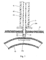
- FIG. 7 is a cross-sectional view depicting a medical system according to the invention used to form an anastomosis with two magnet assemblies;
- FIG. 8 is a cross-sectional view depicting the medical system of FIG. 7 in another configuration
- FIG. 9 is a schematic view depicting a portion of the medical system of FIG. 7 ;
- FIG. 10 is a schematic view similar to FIG. 9 depicting an alternate construction of the medical system of FIG. 7 .
- FIG. 1 depicts a magnetic anastomosis device 20 for use in forming an intestinal bypass anastomosis to treat obesity, in accordance with the teachings of the present invention.
- the magnetic anastomosis device 20 includes first and second magnet assemblies 20a, 20b comprising magnetic cores 26a, 26b which are surrounded by thin metal rims 28a, 28b. Due to the magnetic attraction between the two magnetic cores 26a, 26b, the walls 22, 24 of two adjacent hollow organ may be sandwiched and compressed between the magnet assemblies 20a, 20b, resulting in ischemic necrosis of the walls 22, 24 to produce an anastomosis between the two hollow organ. It will be understood by those skilled in the art that many magnetic anastomosis devices may be employed in conjunction with the present invention.
- the anastomosis will bypass a portion of the small intestine to create a malabsorptive effect, thereby inducing weight loss to treat obesity, although the bypass may be used for other medical purposes.
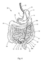
- the digestive tract 30 generally includes an esophagus 32 leading to a stomach 34.
- the small intestine 36 are distal to the stomach 34, and generally include a proximal portion 40 (including the duodenum 38 and jejunum) and a distal portion 42 (which includes the ileum).
- the large intestine 44 i.e. colon leads from the small intestine 36 to the rectum 46.
- proximal and distal in connection with the small intestine is not intended to limit these portions of the small intestine to the duodenum/jejunum and ileum, respectively.
- a bypass may be performed between the duodenum and jejunum, two sections of the jejunum, two sections of the ileum, etc.
- a bypass may be performed between different hollow organs of the digestive tract, such as stomach to small intestine, esophagus to stomach, stomach to large intestine, small intestine to large intestine, etc. Accordingly, it will be recognized that “proximal” and distal” are used herein to simply refer to the relative position of two given sections of the digestive tract relative to each other (the mouth being proximal and the anus being distal).
- the first magnet assembly 20a is placed within the distal portion 42 of the small intestine 36.
- This may be accomplished utilizing a standard enteroscope, and more preferably utilizing a double balloon enteroscope 50 which utilizes two inflatable balloons 51 and conventional double balloon endoscopy procedures, as is known in the art.
- a directing catheter 52 is utilized to position the first magnet assembly 20a beyond a distal end of the enteroscope 50 and within the distal portion 42 of the small intestine 36. It will be recognized by those skilled in the art that other minimally invasive and/or endoscopic procedures for delivering a magnet assembly within the distal portion 42 may be employed.
- another step in the method includes placing the second magnet assembly 20b within the proximal portion 40 of the small intestine 36.
- a simple directing catheter 54 or the like may be utilized to deliver the second magnet assembly 20b.
- placement of the magnet assemblies may be aided by fluoroscopy, ultrasound, fiber optic imaging or other well known guidance techniques.
- the second magnet assembly 20b can be placed in the stomach 34, the duodenum 38 or advanced further into the small intestine 36, as long as it is sufficiently spaced from the first magnet assembly 20a to bypass a portion of the small intestine 36.
- medical instrumentation such as an endoscope 56 having a cutting element 58 is utilized to form an opening 35 in the wall of the stomach 34.
- the cutting element 58 is preferably an electrosurgical tool, although any cutting element capable of being andoscapically utilized may readily be employed.
- any natural orifice e.g., the mouth, anus or vagina
- the endoscope 56 or other device could be introduced through the anus into the large intestine 44, and a perforation formed in the large intestine 44 for accessing the peritoneal cavity.
- the endoscope 56 is passed through the opening 35 in the stomach 34 and steered to locate the first magnet assembly 20a.
- conventional techniques may be utilized for guiding the endoscope 56 through the peritoneal cavity to the distal portion 42 of the small intestine 36.
- a grasping device 60 not according to the present invention is advanced through a working channel of the ondoscope 56, into the peritoneal cavity, and is utilized to engage the small intestine 36 proximate the first magnet assembly 20a.
- the location of the first magnet assembly 20a may be identified in many ways, such as using fluoroscopic, ultrasonic, fiber optics, or other imaging techniques.
- the enteroscope 50 includes a signal emitter 53 at its distal end, and the endoscope 56 includes a detector 57 capable of sensing a signal from the signal emitter 53.
- the enteroscope 50 may include a light source proximate the double balloons 51, and the fiber optic imaging capabilities of the endoscope 56 may be utilized to visualize the light source.
- the enteroscope 50 may also be removed and the first magnet assembly 20a may be located blindly or under fluoroscopy, etc. Again, conventional techniques may be utilized for guiding the endoscope 56 to the distal portion 42 of the small intestine 36, including catheter based imaging systems, or emitters built into the first magnet assembly 20a.
- the endoscope 56 and its grasping device 60 not according to the invention are then utilized to bring the distal portion 40 of the small intestine 36, including the first magnet assembly 20a, into close proximity with the second magnet assembly 20b such that the two magnet assemblies are magnetically coupled.
- An anastomosis is then formed between the proximal portion 40 and distal portion 42 of the small intestine 36.
- the anastomosis may be formed by allowing the magnet assemblies 20a, 20b to engage over an area and induce necrosis of the tissue within the area to form the anastomosis.
- the first and second magnet assemblies 20a, 20b may also be used to approximate the tissue and permit excision of the tissue by a cutting device, thereby more immediately forming the anastomosis.
- the opening 35 in the stomach 34 is then closed utilizing a suturing device 62 or other tissue repair tool that can be endoscopically employed. As they are no longer needed, the enteroscope 50 and endoscope 56 may be withdrawn.
- the bypassed portion of in the small intestine 36 (both leading to and from) may then be closed off utilizing conventional suturing techniques or other known techniques, although the bypassed portion may also be left open, depending on the particular portions of the digestive tract involved. It will be recognized that a laparoscopic approach may be used to bring the first and second magnet assemblies 20a, 20b together.
- a first magnet assembly 20a is placed in the distal portion 42 of the small intestine 36 using the steps previously described.
- an opening 35 is formed within a well of a bodily lumen, depicted here as the stomach 34.
- a smaller opening 35 may be formed because a smaller diameter catheter-based system is utilized.
- a pushing catheter 61 having a directing catheter 64 is utilized to connect the first and second magnet assemblies 20a, 20b.
- the pushing catheter 61 defines a lumen 63 slidably receiving the directing catheter 64.
- the directing catheter 64 includes a distal end 65 having a magnetic portion 66.
- the magnetic portion 66 has been depicted as a simple atraumatic-shaped end cap fitted to the interior lumen of the directing catheter 64. It will be recognized by those skilled in the art that the magnetic portion 66 as well as the directing catheter 64 may take numerous forms.
- the directing catheter 64 is navigated to the first magnet assembly 20a such that the magnetic portion 66 becomes magnetically coupled thereto and engaged with the distal portion 42 of the small intestine 36 ( FIG. 6 ).
- the second magnet assembly 20b defines an aperture 21 sized to receive the directing catheter 64 therein.
- the aperture 21 is sized small than an outer diameter of the pushing catheter 61 such that the pushing catheter 61 may deliver the second magnet assembly 20b into engagement with the first magnet assembly 20a.
- the directing catheter 64 is then retracted proximally such that the first magnet assembly 20a is brought into the vicinity of the stomach 34 and the second magnetic assembly 20b, as shown in FIG. 7 . As shown in FIG.
- the directing catheter 64 is then translated relative to the pushing catheter 61 such that the magnetic portion 66 of the directing catheter 64 is withdrawn substantially inside the lumen 63 of the pushing catheter 61, thereby pushing the second magnet assembly 20b into magnetic attraction with the first magnet assembly 20a.
- an anastomosis may be formed using the previously described steps.
- the orientation of the magnetic poles may take several forms.
- the magnetic portion 66 of the directing catheter 64 has been shown having north (N) and south (S) poles separated by a magnetic center line MC66 that extends perpendicular to the magnetic center line MC20a of the first magnet assembly 20a.
- the magnetic center line MC66 of the magnetic portion 66 has been shown generally parallel to the magnetic center line MC20a of the first magnet assembly 20a, as well as parallel to the magnetic center line MC20b of the second magnet assembly 20b.
- the magnetic portion 66 and the directing catheter 64 are designed to retain the second magnet assembly 20b proximate the distal end 65 thereof.
- the magnetic portion 66 and second magnet assembly 20b are magnetically attracted, as shown. Relative translation of the directing catheter 64 and pushing catheter 61 will be sufficient to overcome the magnetic attraction (and repulsion) of the second magnet assembly 20b and magnetic tip 66 in order to magnetically couple the first and second magnet assemblies 20a, 20b.
- FIG. 10 the magnetic portion 66 and the directing catheter 64 are designed to retain the second magnet assembly 20b proximate the distal end 65 thereof.
- the magnetic portion 66 and second magnet assembly 20b are magnetically attracted, as shown. Relative translation of the directing catheter 64 and pushing catheter 61 will be sufficient to overcome the magnetic attraction (and repulsion) of the second magnet assembly 20b and magnetic tip 66 in order to magnetically couple the first and second magnet assemblies 20a, 20b.
- the second magnet assembly 20b has an aperture 21 that is sized to frictionally engage the exterior of directing catheter 64, but remains slidable relative thereto to permit magnetic coupling of the first and second magnet assemblies 20a, 20b through relative translation of the directing catheter 64 and pushing catheter 61.
- a minimally invasive method for bypassing a portion of the digestive tract e.g., the small intestine
- the complications and other problems utilizing conventional surgical or laparoscopic techniques are minimized or avoided, while retaining control over placement of the anastomosis and hence the bypassed portions of the small intestine.
Abstract
Description
- This invention relates to medical systems for the treatment of obesity, and more particularly for forming an intestinal bypass anastomosis using magnets.
- It is well known that obesity is a very difficult condition to treat. Methods of treatment are varied, and include drugs, behavior therapy, and physical exercise, or often a combinational approach involving two or more of these methods. Unfortunately, results are seldom long term with many patients eventually returning to their original weight over time. For that reason, obesity, particularly morbid obesity, is often considered an incurable condition.
- More invasive approaches have been available which have yielded good results in many patients. These include surgical options such as bariatric surgery, bypass surgery or gastroplasty. However, these procedures carry high risks, and are therefore not appropriate for many patients. Even when carried out laparoscopically, these procedures are still considered major surgery due to the high risk and complication rates.
US 5,690,656 andEP1077047 A2 disclose apparatuses for creating abdominal visceral anastomoses comprising two magnets which are to be coupled together. The magnets are inserted into the body by means of a guide wire in a catheter. After insertion, the two magnets are drawn toward one another through the mutual attraction of their magnetic fields. However, there is no medical instrument assisting in the coupling of the two magnets. - The present invention provides medical systems for forming an intestinal bypass anastomosis for the treatment of obesity that is minimally invasive with reduced complications. This is accomplished by the medical system of claim 1. According to the present invention, a medical instrument is provided for engaging a first magnet assembly and magnetically coupling it to a second magnet assembly to form an anastomosis. The medical instrument generally comprises a directing catheter having a magnetic portion and a pushing catheter defining a lumen receiving the directing catheter. The second magnet assembly defines an aperture sized to receive the directing catheter, and is positionable along the outer periphery of the directing catheter. Relative translation of the pushing catheter and directing catheter causes the second magnet assembly to move distally over the directing catheter for engagement with the first magnet assembly.
- With the inventive medical system, the anastomosis may bypass a portion of the small intestine to create a malabsorptive effect and induce weight loss. A first magnet assembly is placed within the distal section, and a second magnet assembly is placed within the proximal section of the digestive tract. An opening is formed within a wall of a bodily lumen. Medical instrumentation is passed through the opening and is used to engage the distal portion section proximate the first magnet assembly. The distal section is moved such that the first magnet assembly becomes magnetically coupled to the second magnet assembly. An anastomosis is formed proximate the first and second magnet assemblies.
- According to more detailed aspects of this embodiment, the medical instrumentation is preferably capable of being steered, and may take many forms. The medical instrumentation may include a directing catheter or a steerable wire guide having a magnetic tip. In any cases the medical instrumentation includes a magnetic portion, and the step of engaging the distal section includes magnetically coupling the magnetic portion with the first magnet assembly. The medical instrumentation also preferably includes fiber optic imaging capabilities, whereby the engaging step includes visualizing the distal portion of the small intestine. To assist in the location of the first magnet assembly by the medical instrumentation, a signal emitter may be placed within the distal section proximate the first magnet assembly. The medical instrumentation would include a sensor capable of detecting a signal from the signal emitter. The anastomosis forming step may include allowing the first and second magnet assemblies to engage over an area and induce necrosis of the tissue within the area, or may include introduction of an endoscopic cutting instrument proximate the magnet assemblies and excising tissue of the selected bodily lumens.
- According to more detailed aspects of the medical instrument, the aperture in the second magnet assembly is sized smaller than an outer diameter of the pushing catheter. The directing catheter is preferably steerable for navigation and engagement with a first magnet assembly. When the magnetic portion of the directing catheter is magnetically coupled to the first magnet assembly, withdrawal of the directing catheter substantially within the lumen of the pushing catheter causes decoupling of the magnetic portion and the first magnet assembly. The magnetic center line of the magnetic portion may be generally parallel to the magnetic center line of the magnet assembly, or alternatively may be generally perpendicular to the magnetic center line of the second magnet assembly.
- The accompanying drawings incorporated in and forming a part of the specification illustrate several aspects of the present invention, and together with the description serve to explain the principles of the invention. In the drawings;
-
FIG. 1 is a cross-sectional view of two magnet assemblies for forming an anastomosis; -
FIGS, 2-5 depict hollow organ of the digestive tract and a method of forming an anastomosis between two hollow organ of the digestive tract using a grasping device not according to the invention; -
FIG. 6 depicts hollow organ of the digestive tract and a method for forming an anastomosis between two hollow organ of the digestive tract using a medical system according to the invention ; -
FIG. 7 is a cross-sectional view depicting a medical system according to the invention used to form an anastomosis with two magnet assemblies; -
FIG. 8 is a cross-sectional view depicting the medical system ofFIG. 7 in another configuration; -
FIG. 9 is a schematic view depicting a portion of the medical system ofFIG. 7 ; and -
FIG. 10 is a schematic view similar toFIG. 9 depicting an alternate construction of the medical system ofFIG. 7 . - Turning now to the figures,
FIG. 1 depicts amagnetic anastomosis device 20 for use in forming an intestinal bypass anastomosis to treat obesity, in accordance with the teachings of the present invention. Generally, themagnetic anastomosis device 20 includes first andsecond magnet assemblies magnetic cores thin metal rims magnetic cores walls magnet assemblies walls - A method of forming an anastomosis within the digestive tract using a grasping device not according to the invention will now be described with reference to
FIGS. 2-5 . Generally, the anastomosis will bypass a portion of the small intestine to create a malabsorptive effect, thereby inducing weight loss to treat obesity, although the bypass may be used for other medical purposes. As depicted, thedigestive tract 30 generally includes anesophagus 32 leading to astomach 34. Thesmall intestine 36 are distal to thestomach 34, and generally include a proximal portion 40 (including theduodenum 38 and jejunum) and a distal portion 42 (which includes the ileum). The large intestine 44 (i.e. colon) leads from thesmall intestine 36 to therectum 46. - Use of the terms "proximal" and "distal" in connection with the small intestine is not intended to limit these portions of the small intestine to the duodenum/jejunum and ileum, respectively. For example, a bypass may be performed between the duodenum and jejunum, two sections of the jejunum, two sections of the ileum, etc. Likewise, a bypass may be performed between different hollow organs of the digestive tract, such as stomach to small intestine, esophagus to stomach, stomach to large intestine, small intestine to large intestine, etc. Accordingly, it will be recognized that "proximal" and "distal" are used herein to simply refer to the relative position of two given sections of the digestive tract relative to each other (the mouth being proximal and the anus being distal).
- As shown in
FIG. 2 , thefirst magnet assembly 20a is placed within thedistal portion 42 of thesmall intestine 36. This may be accomplished utilizing a standard enteroscope, and more preferably utilizing adouble balloon enteroscope 50 which utilizes twoinflatable balloons 51 and conventional double balloon endoscopy procedures, as is known in the art. A directingcatheter 52 is utilized to position thefirst magnet assembly 20a beyond a distal end of theenteroscope 50 and within thedistal portion 42 of thesmall intestine 36. It will be recognized by those skilled in the art that other minimally invasive and/or endoscopic procedures for delivering a magnet assembly within thedistal portion 42 may be employed. - Turning now to
FIG. 3 , another step in the method includes placing thesecond magnet assembly 20b within theproximal portion 40 of thesmall intestine 36. Asimple directing catheter 54 or the like may be utilized to deliver thesecond magnet assembly 20b. As will be recognized by those skilled in the art, placement of the magnet assemblies may be aided by fluoroscopy, ultrasound, fiber optic imaging or other well known guidance techniques. It will also be recognized by those skilled in the art that thesecond magnet assembly 20b can be placed in thestomach 34, the duodenum 38 or advanced further into thesmall intestine 36, as long as it is sufficiently spaced from thefirst magnet assembly 20a to bypass a portion of thesmall intestine 36. - As also shown in
FIG. 3 , medical instrumentation such as anendoscope 56 having a cuttingelement 58 is utilized to form anopening 35 in the wall of thestomach 34. The cuttingelement 58 is preferably an electrosurgical tool, although any cutting element capable of being andoscapically utilized may readily be employed. It will also be recognized that while access to the peritoneal cavity has been depicted via the mouth andstomach 34, access to the peritoneal cavity through any natural orifice (e.g., the mouth, anus or vagina) may be used to form the opening in the wall of a body lumen connected to the natural orifice to provide access to the peritoneal cavity and thesmall intestine 36. For example, theendoscope 56 or other device could be introduced through the anus into thelarge intestine 44, and a perforation formed in thelarge intestine 44 for accessing the peritoneal cavity. - Turning to
FIG. 4 , theendoscope 56 is passed through theopening 35 in thestomach 34 and steered to locate thefirst magnet assembly 20a. Again, conventional techniques may be utilized for guiding theendoscope 56 through the peritoneal cavity to thedistal portion 42 of thesmall intestine 36. As depicted, a graspingdevice 60 not according to the present invention is advanced through a working channel of theondoscope 56, into the peritoneal cavity, and is utilized to engage thesmall intestine 36 proximate thefirst magnet assembly 20a. The location of thefirst magnet assembly 20a may be identified in many ways, such as using fluoroscopic, ultrasonic, fiber optics, or other imaging techniques. Preferably, theenteroscope 50 includes asignal emitter 53 at its distal end, and theendoscope 56 includes adetector 57 capable of sensing a signal from thesignal emitter 53. For example, theenteroscope 50 may include a light source proximate thedouble balloons 51, and the fiber optic imaging capabilities of theendoscope 56 may be utilized to visualize the light source. Theenteroscope 50 may also be removed and thefirst magnet assembly 20a may be located blindly or under fluoroscopy, etc. Again, conventional techniques may be utilized for guiding theendoscope 56 to thedistal portion 42 of thesmall intestine 36, including catheter based imaging systems, or emitters built into thefirst magnet assembly 20a. - As depicted in
FIG. 5 , theendoscope 56 and its graspingdevice 60 not according to the invention are then utilized to bring thedistal portion 40 of thesmall intestine 36, including thefirst magnet assembly 20a, into close proximity with thesecond magnet assembly 20b such that the two magnet assemblies are magnetically coupled. An anastomosis is then formed between theproximal portion 40 anddistal portion 42 of thesmall intestine 36. The anastomosis may be formed by allowing themagnet assemblies second magnet assemblies - Also shown in
FIG. 5 , theopening 35 in thestomach 34 is then closed utilizing asuturing device 62 or other tissue repair tool that can be endoscopically employed. As they are no longer needed, theenteroscope 50 andendoscope 56 may be withdrawn. The bypassed portion of in the small intestine 36 (both leading to and from) may then be closed off utilizing conventional suturing techniques or other known techniques, although the bypassed portion may also be left open, depending on the particular portions of the digestive tract involved. It will be recognized that a laparoscopic approach may be used to bring the first andsecond magnet assemblies - Turning now to
FIG. 6 and the medical system according to the invention, a method of forming an anastomosis to bypass a portion of the small intestine will be described. Afirst magnet assembly 20a is placed in thedistal portion 42 of thesmall intestine 36 using the steps previously described. Likewise, anopening 35 is formed within a well of a bodily lumen, depicted here as thestomach 34. However, in this embodiment asmaller opening 35 may be formed because a smaller diameter catheter-based system is utilized. Generally, a pushingcatheter 61 having a directingcatheter 64 is utilized to connect the first andsecond magnet assemblies - As best seen in
FIG. 7 , the pushingcatheter 61 defines alumen 63 slidably receiving the directingcatheter 64. The directingcatheter 64 includes adistal end 65 having amagnetic portion 66. Themagnetic portion 66 has been depicted as a simple atraumatic-shaped end cap fitted to the interior lumen of the directingcatheter 64. It will be recognized by those skilled in the art that themagnetic portion 66 as well as the directingcatheter 64 may take numerous forms. The directingcatheter 64 is navigated to thefirst magnet assembly 20a such that themagnetic portion 66 becomes magnetically coupled thereto and engaged with thedistal portion 42 of the small intestine 36 (FIG. 6 ). - It can also be seen in
FIG. 7 that thesecond magnet assembly 20b defines anaperture 21 sized to receive the directingcatheter 64 therein. Theaperture 21 is sized small than an outer diameter of the pushingcatheter 61 such that the pushingcatheter 61 may deliver thesecond magnet assembly 20b into engagement with thefirst magnet assembly 20a. The directingcatheter 64 is then retracted proximally such that thefirst magnet assembly 20a is brought into the vicinity of thestomach 34 and the secondmagnetic assembly 20b, as shown inFIG. 7 . As shown inFIG. 8 , the directingcatheter 64 is then translated relative to the pushingcatheter 61 such that themagnetic portion 66 of the directingcatheter 64 is withdrawn substantially inside thelumen 63 of the pushingcatheter 61, thereby pushing thesecond magnet assembly 20b into magnetic attraction with thefirst magnet assembly 20a. With the first andsecond magnet assemblies stomach 34 and thedistal portion 42 of thesmall intestine 36, an anastomosis may be formed using the previously described steps. - As shown in
FIGS. 9 and 10 , the orientation of the magnetic poles (indicated as "N" and "S") may take several forms. For example, inFIG. 9 themagnetic portion 66 of the directingcatheter 64 has been shown having north (N) and south (S) poles separated by a magnetic center line MC66 that extends perpendicular to the magnetic center line MC20a of the first magnet assembly 20a. inFIG. 10 , the magnetic center line MC66 of themagnetic portion 66 has been shown generally parallel to the magnetic center line MC20a of thefirst magnet assembly 20a, as well as parallel to the magnetic center line MC20b of thesecond magnet assembly 20b. - It will be recognized that the
magnetic portion 66 and the directingcatheter 64 are designed to retain thesecond magnet assembly 20b proximate thedistal end 65 thereof. In the embodiment ofFIG. 10 , themagnetic portion 66 andsecond magnet assembly 20b are magnetically attracted, as shown. Relative translation of the directingcatheter 64 and pushingcatheter 61 will be sufficient to overcome the magnetic attraction (and repulsion) of thesecond magnet assembly 20b andmagnetic tip 66 in order to magnetically couple the first andsecond magnet assemblies FIG. 9 , thesecond magnet assembly 20b has anaperture 21 that is sized to frictionally engage the exterior of directingcatheter 64, but remains slidable relative thereto to permit magnetic coupling of the first andsecond magnet assemblies catheter 64 and pushingcatheter 61. - Accordingly, it will be recognized by those skilled in the art that a minimally invasive method for bypassing a portion of the digestive tract (e.g., the small intestine) is provided to create a malabsorptive effect and induce weight loss. The complications and other problems utilizing conventional surgical or laparoscopic techniques are minimized or avoided, while retaining control over placement of the anastomosis and hence the bypassed portions of the small intestine.
- The foregoing description of various embodiments of the invention has been presented for purposes of illustration and description. It is not intended to be exhaustive or to limit the invention to the precise embodiments disclosed. Numerous modifications or variations are possible in light of the above teachings. The embodiments discussed were chosen and described to provide the best illustration of the principles of the invention and its practical application to thereby enable one of ordinary skill in the art to utilize the invention in various embodiments and with various modifications as are suited to the particular use contemplated. All such modifications and variations are within the scope of the invention as determined by the appended claims.
Claims (6)
- A medical system comprising first and second magnet assemblies (20a, 20b),
and a medical instrument for engaging the first magnet assembly (20a) and magnetically coupling the first magnet assembly (20a) with the second magnet assembly (20b), the medical instrument comprising:a steerable elongate element (64) having a magnetic portion (66); anda pushing catheter (61) defining a lumen (63) slidably receiving the steerablethe second magnet assembly (20b) defines an aperture (21) sized to receive the steerable elongate element (64) such that the second magnet assembly (20b) is positioned on the outer periphery of the steerable elongate element (64), wherein relative translation of the pushing catheter (61) and steerable elongate element (64) causes the second magnet assembly (20b) to move distally over the steerable elongate element (64) for engagement with the first magnet assembly (20a).
elongate element (64); and wherein - The medical system of claim 1, wherein the aperture (21) is sized smaller than an outer diameter of the pushing catheter (61).
- The medical system of claim 1, wherein the aperture (21) is sized to frictionally engage the second magnet assembly (20b) to the steerable elongate element (64).
- The medical system of claim 1, wherein the magnetic portion (66) is magnetically coupled to the first magnet assembly (20a), and wherein the steerable elongate element (64) is substantially withdrawn into the lumen (63) of the pushing catheter (61) to decouple the magnetic portion (66) and first magnet assembly (20a).
- The medical system of claim 1, wherein the magnetic centerline of the magnetic portion (66) is generally parallel to the magnetic centerline of the second magnet assembly (20b).
- The medical system of claim 1, wherein the magnetic centerline of the magnetic portion (66) is generally perpendicular to the magnetic centerline of the second magnet assembly (20b).
Priority Applications (1)
| Application Number | Priority Date | Filing Date | Title |
|---|---|---|---|
| EP10194611A EP2332473A1 (en) | 2007-02-28 | 2008-02-05 | Intestinal bypass using magnets |
Applications Claiming Priority (2)
| Application Number | Priority Date | Filing Date | Title |
|---|---|---|---|
| US90408407P | 2007-02-28 | 2007-02-28 | |
| PCT/US2008/053011 WO2008106279A1 (en) | 2007-02-28 | 2008-02-05 | Intestinal bypass using magnets |
Related Child Applications (1)
| Application Number | Title | Priority Date | Filing Date |
|---|---|---|---|
| EP10194611.9 Division-Into | 2010-12-10 |
Publications (2)
| Publication Number | Publication Date |
|---|---|
| EP2124759A1 EP2124759A1 (en) | 2009-12-02 |
| EP2124759B1 true EP2124759B1 (en) | 2011-06-29 |
Family
ID=39529811
Family Applications (2)
| Application Number | Title | Priority Date | Filing Date |
|---|---|---|---|
| EP20080729010 Active EP2124759B1 (en) | 2007-02-28 | 2008-02-05 | Intestinal bypass using magnets |
| EP10194611A Withdrawn EP2332473A1 (en) | 2007-02-28 | 2008-02-05 | Intestinal bypass using magnets |
Family Applications After (1)
| Application Number | Title | Priority Date | Filing Date |
|---|---|---|---|
| EP10194611A Withdrawn EP2332473A1 (en) | 2007-02-28 | 2008-02-05 | Intestinal bypass using magnets |
Country Status (4)
| Country | Link |
|---|---|
| US (2) | US8864781B2 (en) |
| EP (2) | EP2124759B1 (en) |
| AT (1) | ATE514386T1 (en) |
| WO (1) | WO2008106279A1 (en) |
Cited By (3)
| Publication number | Priority date | Publication date | Assignee | Title |
|---|---|---|---|---|
| US10154844B2 (en) | 2016-07-25 | 2018-12-18 | Virender K. Sharma | Magnetic anastomosis device and delivery system |
| US10561423B2 (en) | 2016-07-25 | 2020-02-18 | Virender K. Sharma | Cardiac shunt device and delivery system |
| US11304698B2 (en) | 2016-07-25 | 2022-04-19 | Virender K. Sharma | Cardiac shunt device and delivery system |
Families Citing this family (40)
| Publication number | Priority date | Publication date | Assignee | Title |
|---|---|---|---|---|
| CA2911795C (en) | 2007-12-21 | 2019-02-26 | Michel Gagner | Methods and devices for endoscopically creating an anastomosis |
| KR20120008492A (en) | 2009-04-03 | 2012-01-30 | 메타모딕스, 인코포레이티드 | Modular gastrointestinal prostheses |
| US9173760B2 (en) | 2009-04-03 | 2015-11-03 | Metamodix, Inc. | Delivery devices and methods for gastrointestinal implants |
| US9278019B2 (en) | 2009-04-03 | 2016-03-08 | Metamodix, Inc | Anchors and methods for intestinal bypass sleeves |
| US8702641B2 (en) | 2009-04-03 | 2014-04-22 | Metamodix, Inc. | Gastrointestinal prostheses having partial bypass configurations |
| JP5449534B2 (en) * | 2009-05-15 | 2014-03-19 | クック メディカル テクノロジーズ エルエルシー | Delivery system for magnetic anastomosis device |
| AU2010271294B2 (en) | 2009-07-10 | 2015-09-03 | Metamodix, Inc. | External anchoring configurations for modular gastrointestinal prostheses |
| WO2011008988A1 (en) | 2009-07-15 | 2011-01-20 | Medical And Surgical Review, P.C. | Incisionless gastric bypass method and devices |
| US20110082370A1 (en) * | 2009-10-02 | 2011-04-07 | Wilson-Cook Medical Inc. | Endoscopic fascia tunneling |
| US8870898B2 (en) | 2010-01-05 | 2014-10-28 | GI Windows, Inc. | Self-assembling magnetic anastomosis device having an exoskeleton |
| BR112012016666A2 (en) | 2010-01-05 | 2018-06-05 | Beacon Endoscopic Corp | methods and apparatus for magnetically induced compression anastomosis between adjacent organs. |
| US20110218476A1 (en) * | 2010-02-12 | 2011-09-08 | Stefan Josef Matthias Kraemer | Apparatus and method for gastric bypass surgery |
| CN101849852B (en) * | 2010-06-13 | 2012-08-29 | 西安交通大学 | Magnetic device for portacaval shunt |
| EP2590577A1 (en) * | 2010-07-06 | 2013-05-15 | Cook Medical Technologies LLC | Devices and methods for anchoring a tube |
| US20130325042A1 (en) * | 2012-05-31 | 2013-12-05 | Izhak Fabian | Pylorus plug and anastomosis |
| AU2014207608A1 (en) | 2013-01-15 | 2015-07-30 | Metamodix, Inc. | System and method for affecting intestinal microbial flora |
| RU2525530C1 (en) * | 2013-03-25 | 2014-08-20 | Евгений Яковлевич Гаткин | Method of recovering functions of intestinal tube in case of short bowel syndrome |
| US20140309669A1 (en) * | 2013-04-14 | 2014-10-16 | Izhak Fabian | Positioning tool for anastomosis |
| US9364238B2 (en) | 2013-04-16 | 2016-06-14 | Ethicon Endo-Surgery, Inc. | Method and apparatus for joining hollow organ sections in anastomosis |
| US11033272B2 (en) | 2013-04-16 | 2021-06-15 | Ethicon Endo-Surgery, Inc. | Methods for partial diversion of the intestinal tract |
| US20150057687A1 (en) * | 2013-08-23 | 2015-02-26 | Cook Medical Technologies Llc | Endovascular delivery system for magnetic compression vascular anastomosis |
| US10039550B2 (en) * | 2013-12-31 | 2018-08-07 | Easy Notes Ltd. | Magnetic anastomosis assembly |
| US20170050040A1 (en) * | 2014-04-28 | 2017-02-23 | The Trustees Of Dartmouth College | Method and magnetic catheter for magnetic nanoparticle treatment of the prostate |
| US10154935B1 (en) * | 2014-05-27 | 2018-12-18 | Bryan L. Ales | Pressure bearing auricular hematoma appliance |
| EP3488795A1 (en) | 2014-07-23 | 2019-05-29 | GI Windows Inc. | Magnetic anastomosis devices and methods of delivery |
| US9943335B2 (en) * | 2014-09-23 | 2018-04-17 | Cook Medical Technologies Llc | Implanted magnets retrieval system and method |
| US10039552B2 (en) | 2014-10-28 | 2018-08-07 | Cook Medical Technologies Llc | Magnetically actuated gating devices, systems, kits, and methods |
| BR112017023997A2 (en) | 2015-05-08 | 2018-07-17 | Gi Windows Inc | storage and loading device, storage and supply system and self-closing compression anastomosis device. |
| US9622897B1 (en) | 2016-03-03 | 2017-04-18 | Metamodix, Inc. | Pyloric anchors and methods for intestinal bypass sleeves |
| DE202017007388U1 (en) | 2016-05-19 | 2021-02-12 | Metamodix, Inc. | Tools for pyloric anchor recovery |
| US10376265B2 (en) | 2017-01-30 | 2019-08-13 | Ethicon Llc | Non-magnetic fragmentable tissue compression devices |
| US10555735B2 (en) | 2017-01-30 | 2020-02-11 | Ethicon Llc | Tissue compression assemblies with biodegradable interlinks |
| CN107928717B (en) * | 2017-11-28 | 2023-11-24 | 崇好科技有限公司 | Magnetic composite device for establishing digestive tract passage |
| AU2019207791B2 (en) * | 2018-01-11 | 2020-11-05 | Boston Scientific Scimed, Inc. | Systems, methods and devices for connecting non-adherent structures |
| JP7374129B2 (en) | 2018-06-02 | 2023-11-06 | ジーアイ ウィンドウズ, インコーポレイテッド | Systems, devices and methods for forming anastomoses |
| WO2022006742A1 (en) * | 2020-07-07 | 2022-01-13 | Bio-Medical Engineering (HK) Limited | Endoscopic magnetic anastomosis system, and methods and devices for forming anastomosis |
| EP4213744A4 (en) * | 2020-09-18 | 2024-03-13 | Gt Metabolic Solutions Inc | Anastomosis formation with magnetic devices having temporary retention member |
| WO2022132351A1 (en) | 2020-12-18 | 2022-06-23 | Gt Metabolic Solutions, Inc. | Devices and methods for assisting magnetic compression anastomosis |
| WO2022225923A1 (en) | 2021-04-20 | 2022-10-27 | G.I. Windows, Inc. | Systems, devices, and methods for endoscope or laparoscopic magnetic navigation |
| EP4329638A1 (en) * | 2021-04-30 | 2024-03-06 | GT Metabolic Solutions, Inc. | Anastomosis formation with magnetic devices having bioresorbable retention member |
Family Cites Families (136)
| Publication number | Priority date | Publication date | Assignee | Title |
|---|---|---|---|---|
| GB1035205A (en) | 1962-11-30 | 1966-07-06 | Yeda Res & Dev | Improvements in the remote controlled propulsion of a body |
| US3299883A (en) | 1963-11-08 | 1967-01-24 | Engelhard Hanovia Inc | Gynecologic instrument |
| SE336642B (en) | 1969-10-28 | 1971-07-12 | Astra Meditec Ab | |
| US3709214A (en) | 1971-10-27 | 1973-01-09 | J Robertson | Gas obturating method |
| US4022208A (en) | 1974-07-25 | 1977-05-10 | Valtchev Konstantin L | Gynecologic instrument |
| US4899744A (en) | 1988-12-15 | 1990-02-13 | Tatsuo Fujitsuka | Apparatus for anastomosing digestive tract |
| US5081997A (en) | 1989-03-09 | 1992-01-21 | Vance Products Incorporated | Echogenic devices, material and method |
| US5197649A (en) * | 1991-10-29 | 1993-03-30 | The Trustees Of Columbia University In The City Of New York | Gastrointestinal endoscoptic stapler |
| US5383849A (en) | 1992-05-11 | 1995-01-24 | Wilson-Cook Medical, Inc. | Method for selective endoscopic cannulation of ductal structures |
| US5330486A (en) * | 1992-07-29 | 1994-07-19 | Wilk Peter J | Laparoscopic or endoscopic anastomosis technique and associated instruments |
| US5297536A (en) | 1992-08-25 | 1994-03-29 | Wilk Peter J | Method for use in intra-abdominal surgery |
| US5458131A (en) | 1992-08-25 | 1995-10-17 | Wilk; Peter J. | Method for use in intra-abdominal surgery |
| US5346501A (en) | 1993-02-05 | 1994-09-13 | Ethicon, Inc. | Laparoscopic absorbable anastomosic fastener and means for applying |
| US5429131A (en) | 1994-02-25 | 1995-07-04 | The Regents Of The University Of California | Magnetized electrode tip catheter |
| US5624430A (en) * | 1994-11-28 | 1997-04-29 | Eton; Darwin | Magnetic device to assist transcorporeal guidewire placement |
| US5690656A (en) | 1995-06-27 | 1997-11-25 | Cook Incorporated | Method and apparatus for creating abdominal visceral anastomoses |
| AU726713B2 (en) * | 1995-10-13 | 2000-11-16 | Transvascular, Inc. | Methods and apparatus for bypassing arterial obstructions and/or performing other transvascular procedures |
| US6579311B1 (en) * | 1996-02-02 | 2003-06-17 | Transvascular, Inc. | Method for interstitial transvascular intervention |
| US6293952B1 (en) | 1997-07-31 | 2001-09-25 | Circon Corporation | Medical instrument system for piercing through tissue |
| US6015414A (en) | 1997-08-29 | 2000-01-18 | Stereotaxis, Inc. | Method and apparatus for magnetically controlling motion direction of a mechanically pushed catheter |
| JP3342021B2 (en) | 1997-10-17 | 2002-11-05 | サーコン コーポレーション | Medical device system that penetrates tissue |
| US20040087985A1 (en) | 1999-03-19 | 2004-05-06 | Amir Loshakove | Graft and connector delivery |
| US6030365A (en) | 1998-06-10 | 2000-02-29 | Laufer; Michael D. | Minimally invasive sterile surgical access device and method |
| CA2261488A1 (en) | 1999-01-21 | 2000-07-21 | Anthony Paolitto | Transabdominal device for performing closed-chest cardiac surgery |
| JP3901421B2 (en) * | 1999-08-19 | 2007-04-04 | 有限会社 パックス オプティカ ジャパン | Organ anastomosis device |
| US6689062B1 (en) | 1999-11-23 | 2004-02-10 | Microaccess Medical Systems, Inc. | Method and apparatus for transesophageal cardiovascular procedures |
| US6527753B2 (en) | 2000-02-29 | 2003-03-04 | Olympus Optical Co., Ltd. | Endoscopic treatment system |
| WO2001074260A1 (en) | 2000-03-24 | 2001-10-11 | Johns Hopkins University | Peritoneal cavity device and method |
| US6802847B1 (en) * | 2000-04-29 | 2004-10-12 | Ventrica, Inc. | Devices and methods for forming magnetic anastomoses and ports in vessels |
| US6464665B1 (en) * | 2000-07-05 | 2002-10-15 | Richard R. Heuser | Catheter apparatus and method for arterializing a vein |
| US6572629B2 (en) | 2000-08-17 | 2003-06-03 | Johns Hopkins University | Gastric reduction endoscopy |
| JP2004508884A (en) | 2000-09-25 | 2004-03-25 | コヒージョン テクノロジーズ, インコーポレイテッド | Resorbable anastomotic stent and plug |
| EP1195174B1 (en) | 2000-10-03 | 2005-01-26 | William Cook Europe ApS | A guide wire |
| US6535764B2 (en) | 2001-05-01 | 2003-03-18 | Intrapace, Inc. | Gastric treatment and diagnosis device and method |
| US7637919B2 (en) | 2002-01-30 | 2009-12-29 | Olympus Corporation | Anastomosis system for performing anastomosis in body |
| US20030225312A1 (en) | 2002-03-18 | 2003-12-04 | Anthony Kalloo | Endoscopic system for treating inside of body cavity |
| JP4405165B2 (en) | 2002-03-19 | 2010-01-27 | オリンパス株式会社 | Endoscope system |
| JP3930757B2 (en) | 2002-04-10 | 2007-06-13 | 有限会社 パックス オプティカ ジャパン | Organ anastomosis device |
| AU2003221976A1 (en) | 2002-04-16 | 2003-11-03 | Tyco Healthcare Group Lp | Method and apparatus for anastomosis including an expandable anchor |
| US6837847B2 (en) | 2002-06-13 | 2005-01-04 | Usgi Medical, Inc. | Shape lockable apparatus and method for advancing an instrument through unsupported anatomy |
| US7666197B2 (en) | 2002-06-19 | 2010-02-23 | Tyco Healthcare Group Lp | Method and apparatus for anastomosis |
| US8066724B2 (en) | 2002-09-12 | 2011-11-29 | Medtronic, Inc. | Anastomosis apparatus and methods |
| US20060025788A1 (en) | 2002-09-25 | 2006-02-02 | By-Pass, Inc. | Anastomotic leg arrangement |
| US8105345B2 (en) | 2002-10-04 | 2012-01-31 | Medtronic, Inc. | Anastomosis apparatus and methods |
| US7351202B2 (en) | 2002-12-05 | 2008-04-01 | Ethicon Endo-Surgery, Inc. | Medical device with track and method of use |
| US20040186349A1 (en) | 2002-12-24 | 2004-09-23 | Usgi Medical Corp. | Apparatus and methods for achieving endoluminal access |
| US20040249367A1 (en) | 2003-01-15 | 2004-12-09 | Usgi Medical Corp. | Endoluminal tool deployment system |
| DE602004015729D1 (en) | 2003-02-11 | 2008-09-25 | Olympus Corp | ABOUT TUBE |
| JP4477382B2 (en) | 2003-03-04 | 2010-06-09 | オリンパス株式会社 | Endoscopic intraperitoneal treatment system |
| GB0307826D0 (en) | 2003-04-04 | 2003-05-07 | Univ London | A device for transfixing and joining tissue |
| US7621924B2 (en) | 2003-04-16 | 2009-11-24 | Tyco Healthcare Group Lp | Method and apparatus for radical prostatectomy anastomosis including an anchor for engaging a body vessel and deployable sutures |
| US7615005B2 (en) | 2003-05-16 | 2009-11-10 | Ethicon Endo-Surgery, Inc. | Medical apparatus for use with an endoscope |
| JP4145200B2 (en) | 2003-06-06 | 2008-09-03 | オリンパス株式会社 | Suture device |
| US6918871B2 (en) | 2003-06-19 | 2005-07-19 | Ethicon Endo-Surgery, Inc. | Method for accessing cavity |
| US7608086B2 (en) | 2003-09-30 | 2009-10-27 | Ethicon Endo-Surgery, Inc. | Anastomosis wire ring device |
| JP2007512098A (en) | 2003-11-26 | 2007-05-17 | ジョンズ ホプキンス ユニバーシティ | Oral transgastric endoscopy |
| US7431726B2 (en) * | 2003-12-23 | 2008-10-07 | Mitralign, Inc. | Tissue fastening systems and methods utilizing magnetic guidance |
| US7618427B2 (en) | 2003-12-29 | 2009-11-17 | Ethicon Endo-Surgery, Inc. | Device and method for intralumenal anastomosis |
| CA2556228C (en) | 2004-02-13 | 2014-05-13 | Satiety, Inc. | Methods for reducing hollow organ volume |
| US20060142790A1 (en) * | 2004-03-23 | 2006-06-29 | Michael Gertner | Methods and devices to facilitate connections between body lumens |
| US7500972B2 (en) | 2004-05-07 | 2009-03-10 | Ethicon Endo-Surgery, Inc. | Device for alternately holding, or effecting relative longitudinal movement, of members of a medical instrument |
| US7232448B2 (en) | 2004-06-17 | 2007-06-19 | Ethicon, Inc. - Usa | Minimally invasive stitching device |
| US20060036267A1 (en) | 2004-08-11 | 2006-02-16 | Usgi Medical Inc. | Methods and apparatus for performing malabsorptive bypass procedures within a patient's gastro-intestinal lumen |
| US8439915B2 (en) * | 2004-09-29 | 2013-05-14 | The Regents Of The University Of California | Apparatus and methods for magnetic alteration of anatomical features |
| WO2006081134A2 (en) | 2005-01-26 | 2006-08-03 | Wilk Patent, Llc | Intra-abdominal medical procedures and device |
| US7766810B2 (en) | 2005-03-10 | 2010-08-03 | Olympus Medical Systems Corp. | Probing method and holding method for luminal organ |
| US20060212063A1 (en) | 2005-03-18 | 2006-09-21 | Wilk Patent, Llc | Surgical device and associated trans-organ surgical method |
| WO2006101715A2 (en) | 2005-03-18 | 2006-09-28 | Wilk Patent, Llc | Intra-abdominal medical device and associated method |
| US7789890B2 (en) | 2005-03-30 | 2010-09-07 | Ethicon Endo-Surgery, Inc. | Harness and balloon catheter assembly and method for use in anastomosis procedures |
| US20060258909A1 (en) | 2005-04-08 | 2006-11-16 | Usgi Medical, Inc. | Methods and apparatus for maintaining sterility during transluminal procedures |
| US20060241344A1 (en) | 2005-04-12 | 2006-10-26 | Wilk Patent, Llc | Intra-abdominal surgical method and associated apparatus |
| US20060241480A1 (en) | 2005-04-12 | 2006-10-26 | Wilk Patent, Llc | Endoscopic medical method and associated device |
| US7963941B2 (en) | 2005-04-12 | 2011-06-21 | Wilk Peter J | Intra-abdominal medical method and associated device |
| US7785251B2 (en) | 2005-04-22 | 2010-08-31 | Wilk Patent, Llc | Port extraction method for trans-organ surgery |
| US20060241570A1 (en) | 2005-04-22 | 2006-10-26 | Wilk Patent, Llc | Intra-abdominal medical method |
| US20060241651A1 (en) | 2005-04-22 | 2006-10-26 | Wilk Patent, Llc | Surgical port device and associated method |
| US20060252997A1 (en) | 2005-04-22 | 2006-11-09 | Wilk Patent, Llc | Medical port device, kit and associated method |
| US8663236B2 (en) | 2005-04-26 | 2014-03-04 | Usgi Medical Inc. | Transgastric abdominal access |
| US20060237023A1 (en) | 2005-04-26 | 2006-10-26 | Usgi Medical Inc. | Transgastric tubal ligation |
| US20060287666A1 (en) | 2005-06-15 | 2006-12-21 | Usgi Medical Inc. | Apparatus and methods for endoluminal advancement |
| US7591828B2 (en) | 2005-07-22 | 2009-09-22 | Ethicon Endo-Surgery, Inc. | Resposable anastomotic ring applier device |
| US20100114124A1 (en) | 2005-08-03 | 2010-05-06 | Brian Kelleher | Method and apparatus for partioning an organ within the body |
| US8021355B2 (en) | 2005-08-12 | 2011-09-20 | Board Of Regents The University Of Texas System | System, kit, and method of transgastric removal of visceral fat and other related methods |
| US20070123840A1 (en) | 2005-10-18 | 2007-05-31 | Usgi Medical, Inc. | Instrument assisted abdominal access |
| US20070112362A1 (en) | 2005-11-14 | 2007-05-17 | Olympus Medical Systems Corp. | Perforation suturing method |
| WO2007063550A2 (en) | 2005-12-02 | 2007-06-07 | Given Imaging Ltd. | System and device for in vivo procedures |
| US9962066B2 (en) | 2005-12-30 | 2018-05-08 | Intuitive Surgical Operations, Inc. | Methods and apparatus to shape flexible entry guides for minimally invasive surgery |
| EP1980194B1 (en) | 2006-01-06 | 2013-05-08 | Olympus Medical Systems Corp. | Trans-natural opening based or transcutaneous medical system |
| US20070163604A1 (en) | 2006-01-13 | 2007-07-19 | Olympus Medical Systems Corp. | Leak test method for medical procedure via natural orifice |
| US20070167675A1 (en) | 2006-01-13 | 2007-07-19 | Olympus Medical Systems Corp. | Overtube and medical procedure via natural orifice using the same |
| US8002695B2 (en) | 2006-01-13 | 2011-08-23 | Olympus Medical Systems Corp. | Medical procedure via natural opening |
| US20070167967A1 (en) | 2006-01-13 | 2007-07-19 | Olympus Medical Systems Corp. | Medical procedure via natural orifice and puncture device |
| US7735489B2 (en) | 2006-01-13 | 2010-06-15 | Olympus Medical Systems Corp. | Endotracheal tube, device for use in medical procedure through natural opening and medical procedure through natural opening |
| US7988656B2 (en) | 2006-01-13 | 2011-08-02 | Olympus Medical Systems Corp. | Natural orifice medical operation and endoscopic overtube |
| US20070163585A1 (en) | 2006-01-13 | 2007-07-19 | Olympus Medical Systems Corp. | Method for accessing abdominal cavity and medical procedure via natural orifice |
| US20070167676A1 (en) | 2006-01-13 | 2007-07-19 | Olympus Medical Systems Corp. | Overtube and medical procedure via natural orifice using the same |
| US20070213702A1 (en) | 2006-03-08 | 2007-09-13 | Olympus Medical Systems Corp. | Medical procedure carried out via a natural opening |
| US7785333B2 (en) | 2006-02-21 | 2010-08-31 | Olympus Medical Systems Corp. | Overtube and operative procedure via bodily orifice |
| US8241279B2 (en) | 2006-02-23 | 2012-08-14 | Olympus Medical Systems Corp. | Overtube and natural opening medical procedures using the same |
| US20070219411A1 (en) | 2006-01-13 | 2007-09-20 | Olympus Medical Systems Corp. | Overtube and endoscopic treatment system |
| US20070260214A1 (en) | 2006-01-13 | 2007-11-08 | Olympus Medical Systems Corp. | Medical procedure through natural body opening |
| US7374567B2 (en) * | 2006-01-25 | 2008-05-20 | Heuser Richard R | Catheter system for connecting adjacent blood vessels |
| US20070213749A1 (en) | 2006-03-08 | 2007-09-13 | Olympus Medical Systems Corp. | Medical procedure performed inside abdominal cavity |
| US20070225734A1 (en) | 2006-03-22 | 2007-09-27 | Minos Medical | Systems and methods for less invasive resolution of maladies of tissue including the appendix, gall bladder, and hemorrhoids |
| EP2012697A4 (en) | 2006-04-29 | 2010-07-21 | Univ Texas | Devices for use in transluminal and endoluminal surgery |
| US20070270629A1 (en) | 2006-05-19 | 2007-11-22 | Charles Filipi J | System and techniques for magnetic manipulation of internal organs during minimally invasive surgery |
| EP2037794B1 (en) | 2006-06-13 | 2021-10-27 | Intuitive Surgical Operations, Inc. | Minimally invasive surgical system |
| US7815566B2 (en) | 2006-07-20 | 2010-10-19 | Ethicon Endo-Surgery, Inc. | Methods for stabilizing and positioning an endoscope and surgical procedures |
| US20080051626A1 (en) | 2006-08-28 | 2008-02-28 | Olympus Medical Systems Corp. | Fistulectomy method between first duct and second duct, ultrasonic endoscope, catheter with balloon, magnet retaining device, and magnet set |
| US8475453B2 (en) | 2006-10-06 | 2013-07-02 | Covidien Lp | Endoscopic vessel sealer and divider having a flexible articulating shaft |
| JP4584230B2 (en) | 2006-11-14 | 2010-11-17 | オリンパスメディカルシステムズ株式会社 | Clip device |
| US8221443B2 (en) | 2006-11-15 | 2012-07-17 | Mayo Foundation For Medical Education And Research | Submucosal endoscopy with mucosal flap methods and kits |
| US8025670B2 (en) | 2006-11-22 | 2011-09-27 | Minos Medical | Methods and apparatus for natural orifice vaginal hysterectomy |
| JP2008161570A (en) | 2006-12-28 | 2008-07-17 | Olympus Medical Systems Corp | Ultrasonic endoscope system |
| US20080171907A1 (en) | 2007-01-12 | 2008-07-17 | Ethicon Endo-Surgery, Inc. | Magnetic Tissue Grasping |
| US20080183039A1 (en) | 2007-01-26 | 2008-07-31 | Ethicon Endo-Surgery, Inc. | Balloon Positioning System for Endoscopic Access |
| US20080200934A1 (en) * | 2007-02-15 | 2008-08-21 | Fox William D | Surgical devices and methods using magnetic force to form an anastomosis |
| US20080200762A1 (en) | 2007-02-16 | 2008-08-21 | Stokes Michael J | Flexible endoscope shapelock |
| US8460314B2 (en) | 2007-02-26 | 2013-06-11 | Olympus Medical Systems Corp. | Application of procedure through natural orifice |
| US8155728B2 (en) | 2007-08-22 | 2012-04-10 | Ethicon Endo-Surgery, Inc. | Medical system, method, and storage medium concerning a natural orifice transluminal medical procedure |
| US20080228203A1 (en) | 2007-03-15 | 2008-09-18 | Minos Medical | System and method for translumenal closure in natural orifice surgery |
| JP4996311B2 (en) | 2007-04-05 | 2012-08-08 | オリンパスメディカルシステムズ株式会社 | Treatment instrument system |
| US7967741B2 (en) | 2007-05-01 | 2011-06-28 | Ethicon Endo-Surgery, Inc. | Endoscopic guide device |
| US20090023985A1 (en) | 2007-06-14 | 2009-01-22 | Usgi Medical, Inc. | Endoluminal instrument management system |
| US20090054728A1 (en) | 2007-08-21 | 2009-02-26 | Trusty Robert M | Manipulatable guide system and methods for natural orifice translumenal endoscopic surgery |
| JP2009072368A (en) | 2007-09-20 | 2009-04-09 | Olympus Medical Systems Corp | Medical apparatus |
| US20090182195A1 (en) | 2008-01-11 | 2009-07-16 | Ethicon Endo-Surgery, Inc. | Endoscopic guide system |
| US8792966B2 (en) | 2008-03-03 | 2014-07-29 | Ethicon Endo-Surgery, Inc. | Transluminal tissue markers |
| US8262680B2 (en) | 2008-03-10 | 2012-09-11 | Ethicon Endo-Surgery, Inc. | Anastomotic device |
| US10350050B2 (en) | 2008-05-01 | 2019-07-16 | Ethicon Endo-Surgery, Inc. | Method for gastric volume reduction surgery |
| US20090281559A1 (en) | 2008-05-06 | 2009-11-12 | Ethicon Endo-Surgery, Inc. | Anastomosis patch |
| US20100010520A1 (en) | 2008-07-11 | 2010-01-14 | Olympus Medical Systems Corp. | Tissue fastener |
| US8685046B2 (en) | 2008-08-05 | 2014-04-01 | Covidien Lp | Magnetic compression anastomosis device |
| US8241204B2 (en) | 2008-08-29 | 2012-08-14 | Ethicon Endo-Surgery, Inc. | Articulating end cap |
| US8425406B2 (en) | 2008-12-19 | 2013-04-23 | Boston Scientific Scimed, Inc. | Systems and methods for directing instruments to varying positions at the distal end of a guide tube |
| US8828031B2 (en) | 2009-01-12 | 2014-09-09 | Ethicon Endo-Surgery, Inc. | Apparatus for forming an anastomosis |
-
2008
- 2008-02-05 WO PCT/US2008/053011 patent/WO2008106279A1/en active Application Filing
- 2008-02-05 AT AT08729010T patent/ATE514386T1/en not_active IP Right Cessation
- 2008-02-05 EP EP20080729010 patent/EP2124759B1/en active Active
- 2008-02-05 US US12/025,985 patent/US8864781B2/en active Active
- 2008-02-05 EP EP10194611A patent/EP2332473A1/en not_active Withdrawn
-
2010
- 2010-11-12 US US12/945,178 patent/US9226753B2/en active Active
Cited By (3)
| Publication number | Priority date | Publication date | Assignee | Title |
|---|---|---|---|---|
| US10154844B2 (en) | 2016-07-25 | 2018-12-18 | Virender K. Sharma | Magnetic anastomosis device and delivery system |
| US10561423B2 (en) | 2016-07-25 | 2020-02-18 | Virender K. Sharma | Cardiac shunt device and delivery system |
| US11304698B2 (en) | 2016-07-25 | 2022-04-19 | Virender K. Sharma | Cardiac shunt device and delivery system |
Also Published As
| Publication number | Publication date |
|---|---|
| EP2332473A1 (en) | 2011-06-15 |
| ATE514386T1 (en) | 2011-07-15 |
| US20080208224A1 (en) | 2008-08-28 |
| WO2008106279A1 (en) | 2008-09-04 |
| EP2124759A1 (en) | 2009-12-02 |
| US8864781B2 (en) | 2014-10-21 |
| US20110060353A1 (en) | 2011-03-10 |
| US9226753B2 (en) | 2016-01-05 |
Similar Documents
| Publication | Publication Date | Title |
|---|---|---|
| EP2124759B1 (en) | Intestinal bypass using magnets | |
| EP2260752B1 (en) | Magnet indwelling device | |
| US6988987B2 (en) | Guide tube | |
| US8628548B2 (en) | Delivery system for magnetic anastomosis device | |
| US20120089089A1 (en) | Methods of magnetically guiding and axially aligning distal ends of surgical devices | |
| US20010049497A1 (en) | Methods and devices for diagnostic and therapeutic interventions in the peritoneal cavity | |
| JP2019509814A (en) | Targeting system to provide accurate placement of a magnetic anastomosis device | |
| US20210153868A1 (en) | Systems, methods and devices for connecting non-adherent structures | |
| JP2010502326A (en) | Surgical instrument for performing intraluminal and / or transluminal anastomosis | |
| EP2717789B1 (en) | Delivery system for magnetic anastomosis device | |
| US20210100668A1 (en) | Thermopuncture stent implantation device | |
| Kume et al. | The use of magnetic anchors in the bowel lumen for laparoscopic anterior resection of rectosigmoid colon in pigs: with video | |
| US20240099783A1 (en) | Beacon devices, systems, and methods for medical procedures | |
| EP2976020A1 (en) | A miniature robotic device applicable to a flexible endoscope for the surgical dissection of gastro-intestinal tract surface neoplasms | |
| US20230255722A1 (en) | Wireless devices, systems, and methods for endoscopic positioning | |
| WO2019091403A1 (en) | Double-balloon catheter device for gastrointestinal anastomosis |
Legal Events
| Date | Code | Title | Description |
|---|---|---|---|
| PUAI | Public reference made under article 153(3) epc to a published international application that has entered the european phase |
Free format text: ORIGINAL CODE: 0009012 |
|
| 17P | Request for examination filed |
Effective date: 20090904 |
|
| AK | Designated contracting states |
Kind code of ref document: A1 Designated state(s): AT BE BG CH CY CZ DE DK EE ES FI FR GB GR HR HU IE IS IT LI LT LU LV MC MT NL NO PL PT RO SE SI SK TR |
|
| RIN1 | Information on inventor provided before grant (corrected) |
Inventor name: SURTI, VIHAR, C. Inventor name: DILLON, TRAVIS, E. |
|
| DAX | Request for extension of the european patent (deleted) | ||
| 17Q | First examination report despatched |
Effective date: 20100507 |
|
| GRAP | Despatch of communication of intention to grant a patent |
Free format text: ORIGINAL CODE: EPIDOSNIGR1 |
|
| GRAS | Grant fee paid |
Free format text: ORIGINAL CODE: EPIDOSNIGR3 |
|
| GRAA | (expected) grant |
Free format text: ORIGINAL CODE: 0009210 |
|
| AK | Designated contracting states |
Kind code of ref document: B1 Designated state(s): AT BE BG CH CY CZ DE DK EE ES FI FR GB GR HR HU IE IS IT LI LT LU LV MC MT NL NO PL PT RO SE SI SK TR |
|
| REG | Reference to a national code |
Ref country code: GB Ref legal event code: FG4D |
|
| REG | Reference to a national code |
Ref country code: CH Ref legal event code: EP |
|
| REG | Reference to a national code |
Ref country code: IE Ref legal event code: FG4D |
|
| REG | Reference to a national code |
Ref country code: DE Ref legal event code: R096 Ref document number: 602008007944 Country of ref document: DE Effective date: 20110818 |
|
| REG | Reference to a national code |
Ref country code: NL Ref legal event code: VDEP Effective date: 20110629 |
|
| RAP2 | Party data changed (patent owner data changed or rights of a patent transferred) |
Owner name: COOK MEDICAL TECHNOLOGIES LLC |
|
| PG25 | Lapsed in a contracting state [announced via postgrant information from national office to epo] |
Ref country code: SE Free format text: LAPSE BECAUSE OF FAILURE TO SUBMIT A TRANSLATION OF THE DESCRIPTION OR TO PAY THE FEE WITHIN THE PRESCRIBED TIME-LIMIT Effective date: 20110629 Ref country code: LT Free format text: LAPSE BECAUSE OF FAILURE TO SUBMIT A TRANSLATION OF THE DESCRIPTION OR TO PAY THE FEE WITHIN THE PRESCRIBED TIME-LIMIT Effective date: 20110629 Ref country code: HR Free format text: LAPSE BECAUSE OF FAILURE TO SUBMIT A TRANSLATION OF THE DESCRIPTION OR TO PAY THE FEE WITHIN THE PRESCRIBED TIME-LIMIT Effective date: 20110629 Ref country code: NO Free format text: LAPSE BECAUSE OF FAILURE TO SUBMIT A TRANSLATION OF THE DESCRIPTION OR TO PAY THE FEE WITHIN THE PRESCRIBED TIME-LIMIT Effective date: 20110929 |
|
| PG25 | Lapsed in a contracting state [announced via postgrant information from national office to epo] |
Ref country code: FI Free format text: LAPSE BECAUSE OF FAILURE TO SUBMIT A TRANSLATION OF THE DESCRIPTION OR TO PAY THE FEE WITHIN THE PRESCRIBED TIME-LIMIT Effective date: 20110629 Ref country code: SI Free format text: LAPSE BECAUSE OF FAILURE TO SUBMIT A TRANSLATION OF THE DESCRIPTION OR TO PAY THE FEE WITHIN THE PRESCRIBED TIME-LIMIT Effective date: 20110629 Ref country code: LV Free format text: LAPSE BECAUSE OF FAILURE TO SUBMIT A TRANSLATION OF THE DESCRIPTION OR TO PAY THE FEE WITHIN THE PRESCRIBED TIME-LIMIT Effective date: 20110629 Ref country code: GR Free format text: LAPSE BECAUSE OF FAILURE TO SUBMIT A TRANSLATION OF THE DESCRIPTION OR TO PAY THE FEE WITHIN THE PRESCRIBED TIME-LIMIT Effective date: 20110930 Ref country code: AT Free format text: LAPSE BECAUSE OF FAILURE TO SUBMIT A TRANSLATION OF THE DESCRIPTION OR TO PAY THE FEE WITHIN THE PRESCRIBED TIME-LIMIT Effective date: 20110629 |
|
| PG25 | Lapsed in a contracting state [announced via postgrant information from national office to epo] |
Ref country code: BE Free format text: LAPSE BECAUSE OF FAILURE TO SUBMIT A TRANSLATION OF THE DESCRIPTION OR TO PAY THE FEE WITHIN THE PRESCRIBED TIME-LIMIT Effective date: 20110629 |
|
| RAP2 | Party data changed (patent owner data changed or rights of a patent transferred) |
Owner name: COOK MEDICAL TECHNOLOGIES LLC |
|
| PG25 | Lapsed in a contracting state [announced via postgrant information from national office to epo] |
Ref country code: CZ Free format text: LAPSE BECAUSE OF FAILURE TO SUBMIT A TRANSLATION OF THE DESCRIPTION OR TO PAY THE FEE WITHIN THE PRESCRIBED TIME-LIMIT Effective date: 20110629 Ref country code: IS Free format text: LAPSE BECAUSE OF FAILURE TO SUBMIT A TRANSLATION OF THE DESCRIPTION OR TO PAY THE FEE WITHIN THE PRESCRIBED TIME-LIMIT Effective date: 20111029 Ref country code: PT Free format text: LAPSE BECAUSE OF FAILURE TO SUBMIT A TRANSLATION OF THE DESCRIPTION OR TO PAY THE FEE WITHIN THE PRESCRIBED TIME-LIMIT Effective date: 20111031 Ref country code: EE Free format text: LAPSE BECAUSE OF FAILURE TO SUBMIT A TRANSLATION OF THE DESCRIPTION OR TO PAY THE FEE WITHIN THE PRESCRIBED TIME-LIMIT Effective date: 20110629 Ref country code: NL Free format text: LAPSE BECAUSE OF FAILURE TO SUBMIT A TRANSLATION OF THE DESCRIPTION OR TO PAY THE FEE WITHIN THE PRESCRIBED TIME-LIMIT Effective date: 20110629 |
|
| PG25 | Lapsed in a contracting state [announced via postgrant information from national office to epo] |
Ref country code: PL Free format text: LAPSE BECAUSE OF FAILURE TO SUBMIT A TRANSLATION OF THE DESCRIPTION OR TO PAY THE FEE WITHIN THE PRESCRIBED TIME-LIMIT Effective date: 20110629 Ref country code: SK Free format text: LAPSE BECAUSE OF FAILURE TO SUBMIT A TRANSLATION OF THE DESCRIPTION OR TO PAY THE FEE WITHIN THE PRESCRIBED TIME-LIMIT Effective date: 20110629 Ref country code: CY Free format text: LAPSE BECAUSE OF FAILURE TO SUBMIT A TRANSLATION OF THE DESCRIPTION OR TO PAY THE FEE WITHIN THE PRESCRIBED TIME-LIMIT Effective date: 20110629 Ref country code: RO Free format text: LAPSE BECAUSE OF FAILURE TO SUBMIT A TRANSLATION OF THE DESCRIPTION OR TO PAY THE FEE WITHIN THE PRESCRIBED TIME-LIMIT Effective date: 20110629 |
|
| PLBE | No opposition filed within time limit |
Free format text: ORIGINAL CODE: 0009261 |
|
| STAA | Information on the status of an ep patent application or granted ep patent |
Free format text: STATUS: NO OPPOSITION FILED WITHIN TIME LIMIT |
|
| PG25 | Lapsed in a contracting state [announced via postgrant information from national office to epo] |
Ref country code: IT Free format text: LAPSE BECAUSE OF FAILURE TO SUBMIT A TRANSLATION OF THE DESCRIPTION OR TO PAY THE FEE WITHIN THE PRESCRIBED TIME-LIMIT Effective date: 20110629 |
|
| 26N | No opposition filed |
Effective date: 20120330 |
|
| PG25 | Lapsed in a contracting state [announced via postgrant information from national office to epo] |
Ref country code: DK Free format text: LAPSE BECAUSE OF FAILURE TO SUBMIT A TRANSLATION OF THE DESCRIPTION OR TO PAY THE FEE WITHIN THE PRESCRIBED TIME-LIMIT Effective date: 20110629 |
|
| REG | Reference to a national code |
Ref country code: DE Ref legal event code: R097 Ref document number: 602008007944 Country of ref document: DE Effective date: 20120330 |
|
| PG25 | Lapsed in a contracting state [announced via postgrant information from national office to epo] |
Ref country code: MC Free format text: LAPSE BECAUSE OF NON-PAYMENT OF DUE FEES Effective date: 20120229 |
|
| REG | Reference to a national code |
Ref country code: CH Ref legal event code: PL |
|
| PG25 | Lapsed in a contracting state [announced via postgrant information from national office to epo] |
Ref country code: CH Free format text: LAPSE BECAUSE OF NON-PAYMENT OF DUE FEES Effective date: 20120229 Ref country code: LI Free format text: LAPSE BECAUSE OF NON-PAYMENT OF DUE FEES Effective date: 20120229 |
|
| REG | Reference to a national code |
Ref country code: FR Ref legal event code: ST Effective date: 20121031 |
|
| PG25 | Lapsed in a contracting state [announced via postgrant information from national office to epo] |
Ref country code: FR Free format text: LAPSE BECAUSE OF NON-PAYMENT OF DUE FEES Effective date: 20120229 |
|
| PG25 | Lapsed in a contracting state [announced via postgrant information from national office to epo] |
Ref country code: ES Free format text: LAPSE BECAUSE OF FAILURE TO SUBMIT A TRANSLATION OF THE DESCRIPTION OR TO PAY THE FEE WITHIN THE PRESCRIBED TIME-LIMIT Effective date: 20111010 |
|
| PG25 | Lapsed in a contracting state [announced via postgrant information from national office to epo] |
Ref country code: BG Free format text: LAPSE BECAUSE OF FAILURE TO SUBMIT A TRANSLATION OF THE DESCRIPTION OR TO PAY THE FEE WITHIN THE PRESCRIBED TIME-LIMIT Effective date: 20110929 |
|
| PG25 | Lapsed in a contracting state [announced via postgrant information from national office to epo] |
Ref country code: MT Free format text: LAPSE BECAUSE OF FAILURE TO SUBMIT A TRANSLATION OF THE DESCRIPTION OR TO PAY THE FEE WITHIN THE PRESCRIBED TIME-LIMIT Effective date: 20110629 |
|
| PG25 | Lapsed in a contracting state [announced via postgrant information from national office to epo] |
Ref country code: TR Free format text: LAPSE BECAUSE OF FAILURE TO SUBMIT A TRANSLATION OF THE DESCRIPTION OR TO PAY THE FEE WITHIN THE PRESCRIBED TIME-LIMIT Effective date: 20110629 |
|
| PG25 | Lapsed in a contracting state [announced via postgrant information from national office to epo] |
Ref country code: LU Free format text: LAPSE BECAUSE OF NON-PAYMENT OF DUE FEES Effective date: 20120205 |
|
| PG25 | Lapsed in a contracting state [announced via postgrant information from national office to epo] |
Ref country code: HU Free format text: LAPSE BECAUSE OF FAILURE TO SUBMIT A TRANSLATION OF THE DESCRIPTION OR TO PAY THE FEE WITHIN THE PRESCRIBED TIME-LIMIT Effective date: 20080205 |
|
| PGFP | Annual fee paid to national office [announced via postgrant information from national office to epo] |
Ref country code: IE Payment date: 20230127 Year of fee payment: 16 |
|
| P01 | Opt-out of the competence of the unified patent court (upc) registered |
Effective date: 20230602 |
|
| PGFP | Annual fee paid to national office [announced via postgrant information from national office to epo] |
Ref country code: IE Payment date: 20240126 Year of fee payment: 17 |
|
| PGFP | Annual fee paid to national office [announced via postgrant information from national office to epo] |
Ref country code: DE Payment date: 20240109 Year of fee payment: 17 Ref country code: GB Payment date: 20240111 Year of fee payment: 17 |