EP2122169B1 - Fluid machine - Google Patents
Fluid machine Download PDFInfo
- Publication number
- EP2122169B1 EP2122169B1 EP07856620.5A EP07856620A EP2122169B1 EP 2122169 B1 EP2122169 B1 EP 2122169B1 EP 07856620 A EP07856620 A EP 07856620A EP 2122169 B1 EP2122169 B1 EP 2122169B1
- Authority
- EP
- European Patent Office
- Prior art keywords
- fluid
- working machine
- rotor
- linear motor
- piston
- Prior art date
- Legal status (The legal status is an assumption and is not a legal conclusion. Google has not performed a legal analysis and makes no representation as to the accuracy of the status listed.)
- Active
Links
- 239000012530 fluid Substances 0.000 title claims description 72
- 230000006835 compression Effects 0.000 claims description 35
- 238000007906 compression Methods 0.000 claims description 35
- 239000007789 gas Substances 0.000 claims description 26
- 238000001816 cooling Methods 0.000 claims description 16
- 239000002826 coolant Substances 0.000 claims description 10
- 239000007787 solid Substances 0.000 claims description 8
- 239000007788 liquid Substances 0.000 description 9
- 238000007789 sealing Methods 0.000 description 8
- 239000001257 hydrogen Substances 0.000 description 7
- 229910052739 hydrogen Inorganic materials 0.000 description 7
- UFHFLCQGNIYNRP-UHFFFAOYSA-N Hydrogen Chemical compound [H][H] UFHFLCQGNIYNRP-UHFFFAOYSA-N 0.000 description 4
- 150000002431 hydrogen Chemical class 0.000 description 3
- 230000003068 static effect Effects 0.000 description 3
- 230000001360 synchronised effect Effects 0.000 description 3
- 239000000919 ceramic Substances 0.000 description 2
- 230000008878 coupling Effects 0.000 description 2
- 238000010168 coupling process Methods 0.000 description 2
- 238000005859 coupling reaction Methods 0.000 description 2
- 230000006698 induction Effects 0.000 description 2
- 239000007791 liquid phase Substances 0.000 description 2
- 239000002184 metal Substances 0.000 description 2
- 230000005540 biological transmission Effects 0.000 description 1
- 230000015572 biosynthetic process Effects 0.000 description 1
- 238000006243 chemical reaction Methods 0.000 description 1
- 230000006735 deficit Effects 0.000 description 1
- 238000006073 displacement reaction Methods 0.000 description 1
- 238000005516 engineering process Methods 0.000 description 1
- 230000005284 excitation Effects 0.000 description 1
- 238000007710 freezing Methods 0.000 description 1
- 210000004907 gland Anatomy 0.000 description 1
- 238000010438 heat treatment Methods 0.000 description 1
- 230000003993 interaction Effects 0.000 description 1
- 239000002608 ionic liquid Substances 0.000 description 1
- 238000005461 lubrication Methods 0.000 description 1
- 238000004519 manufacturing process Methods 0.000 description 1
- 238000005192 partition Methods 0.000 description 1
- 230000002285 radioactive effect Effects 0.000 description 1
- 239000003507 refrigerant Substances 0.000 description 1
- 238000009987 spinning Methods 0.000 description 1
- 238000003860 storage Methods 0.000 description 1
- 231100000331 toxic Toxicity 0.000 description 1
- 230000002588 toxic effect Effects 0.000 description 1
- 238000004804 winding Methods 0.000 description 1
Images

Classifications
-
- F—MECHANICAL ENGINEERING; LIGHTING; HEATING; WEAPONS; BLASTING
- F04—POSITIVE - DISPLACEMENT MACHINES FOR LIQUIDS; PUMPS FOR LIQUIDS OR ELASTIC FLUIDS
- F04B—POSITIVE-DISPLACEMENT MACHINES FOR LIQUIDS; PUMPS
- F04B35/00—Piston pumps specially adapted for elastic fluids and characterised by the driving means to their working members, or by combination with, or adaptation to, specific driving engines or motors, not otherwise provided for
- F04B35/04—Piston pumps specially adapted for elastic fluids and characterised by the driving means to their working members, or by combination with, or adaptation to, specific driving engines or motors, not otherwise provided for the means being electric
- F04B35/045—Piston pumps specially adapted for elastic fluids and characterised by the driving means to their working members, or by combination with, or adaptation to, specific driving engines or motors, not otherwise provided for the means being electric using solenoids
-
- F—MECHANICAL ENGINEERING; LIGHTING; HEATING; WEAPONS; BLASTING
- F04—POSITIVE - DISPLACEMENT MACHINES FOR LIQUIDS; PUMPS FOR LIQUIDS OR ELASTIC FLUIDS
- F04B—POSITIVE-DISPLACEMENT MACHINES FOR LIQUIDS; PUMPS
- F04B17/00—Pumps characterised by combination with, or adaptation to, specific driving engines or motors
- F04B17/03—Pumps characterised by combination with, or adaptation to, specific driving engines or motors driven by electric motors
- F04B17/04—Pumps characterised by combination with, or adaptation to, specific driving engines or motors driven by electric motors using solenoids
- F04B17/042—Pumps characterised by combination with, or adaptation to, specific driving engines or motors driven by electric motors using solenoids the solenoid motor being separated from the fluid flow
- F04B17/044—Pumps characterised by combination with, or adaptation to, specific driving engines or motors driven by electric motors using solenoids the solenoid motor being separated from the fluid flow using solenoids directly actuating the piston
-
- F—MECHANICAL ENGINEERING; LIGHTING; HEATING; WEAPONS; BLASTING
- F04—POSITIVE - DISPLACEMENT MACHINES FOR LIQUIDS; PUMPS FOR LIQUIDS OR ELASTIC FLUIDS
- F04B—POSITIVE-DISPLACEMENT MACHINES FOR LIQUIDS; PUMPS
- F04B25/00—Multi-stage pumps
- F04B25/005—Multi-stage pumps with two cylinders
-
- F—MECHANICAL ENGINEERING; LIGHTING; HEATING; WEAPONS; BLASTING
- F04—POSITIVE - DISPLACEMENT MACHINES FOR LIQUIDS; PUMPS FOR LIQUIDS OR ELASTIC FLUIDS
- F04B—POSITIVE-DISPLACEMENT MACHINES FOR LIQUIDS; PUMPS
- F04B25/00—Multi-stage pumps
- F04B25/02—Multi-stage pumps of stepped piston type
-
- F—MECHANICAL ENGINEERING; LIGHTING; HEATING; WEAPONS; BLASTING
- F04—POSITIVE - DISPLACEMENT MACHINES FOR LIQUIDS; PUMPS FOR LIQUIDS OR ELASTIC FLUIDS
- F04B—POSITIVE-DISPLACEMENT MACHINES FOR LIQUIDS; PUMPS
- F04B39/00—Component parts, details, or accessories, of pumps or pumping systems specially adapted for elastic fluids, not otherwise provided for in, or of interest apart from, groups F04B25/00 - F04B37/00
- F04B39/0005—Component parts, details, or accessories, of pumps or pumping systems specially adapted for elastic fluids, not otherwise provided for in, or of interest apart from, groups F04B25/00 - F04B37/00 adaptations of pistons
- F04B39/0011—Component parts, details, or accessories, of pumps or pumping systems specially adapted for elastic fluids, not otherwise provided for in, or of interest apart from, groups F04B25/00 - F04B37/00 adaptations of pistons liquid pistons
-
- F—MECHANICAL ENGINEERING; LIGHTING; HEATING; WEAPONS; BLASTING
- F04—POSITIVE - DISPLACEMENT MACHINES FOR LIQUIDS; PUMPS FOR LIQUIDS OR ELASTIC FLUIDS
- F04B—POSITIVE-DISPLACEMENT MACHINES FOR LIQUIDS; PUMPS
- F04B39/00—Component parts, details, or accessories, of pumps or pumping systems specially adapted for elastic fluids, not otherwise provided for in, or of interest apart from, groups F04B25/00 - F04B37/00
- F04B39/06—Cooling; Heating; Prevention of freezing
- F04B39/064—Cooling by a cooling jacket in the pump casing
-
- F—MECHANICAL ENGINEERING; LIGHTING; HEATING; WEAPONS; BLASTING
- F04—POSITIVE - DISPLACEMENT MACHINES FOR LIQUIDS; PUMPS FOR LIQUIDS OR ELASTIC FLUIDS
- F04F—PUMPING OF FLUID BY DIRECT CONTACT OF ANOTHER FLUID OR BY USING INERTIA OF FLUID TO BE PUMPED; SIPHONS
- F04F1/00—Pumps using positively or negatively pressurised fluid medium acting directly on the liquid to be pumped
- F04F1/06—Pumps using positively or negatively pressurised fluid medium acting directly on the liquid to be pumped the fluid medium acting on the surface of the liquid to be pumped
Definitions
- the invention relates to a fluid working machine for compressing or conveying fluids, in particular for compressing gases to high pressures, with a linear motor, at least one cylinder, a solid-state piston axially movable in the cylinder, at least one between the cylinder and the solid-body piston or the liquid piston formed compression space, and valves for the inlet and the outlet of the fluid, which are arranged in the region of the at least one compression space, wherein the linear motor transmits a translational driving force to the solid-state piston and the solid-state piston is enclosed in the region of the linear motor of a fixed can, so in that a cylinder interior is formed between the solid-body piston and the can.
- Fluid power machines are known in various embodiments and variants of the prior art.
- the fluid working machines can be subdivided first according to whether they are provided for conveying or compressing liquids or gases.
- Fluid power machines used to convey fluids are also commonly referred to as pumps, while fluid power machines are referred to as compressors for compressing gases.
- fluid working machines can also be distinguished by the type of drive force - hydraulic, electric or electro-magnetic - as well as the type of drive movement - rotational or translational.
- the present invention relates to a fluid working machine in which the driving force is generated by a linear motor which exerts a translational driving force on a piston guided in a cylinder directly, that is, without converting a rotational movement via a gear. If a gas is to be compressed with such a fluid working machine, then the machine can also be referred to as a piston compressor or as a linear compressor.
- the linear motor consists essentially of a stator or stator and a rotor or actuator, wherein the linear motor as well as a rotating motor may be formed as an asynchronous or synchronous linear motor.
- the linear motor then corresponds to a developed asynchronous motor with a squirrel-cage rotor or a permanently excited synchronous motor, wherein a traveling field is generated by the coil or winding of the stator instead of a rotating field.
- the power transmission takes place, as in induction machines, either by voltage induction in the squirrel-cage rotor of the asynchronous motor or by interaction with the field of the permanent magnets of the synchronous motor.
- a previously described linear compressor is known in which the magnet of the rotor is fixed to a magnetic frame which is fixedly mounted on an end face of the piston.
- a cooling channel is provided for cooling the linear motor, by which the coil of the stator mounted on a coil holder is cooled with a coolant.
- a pump is provided which promotes oil within a hermetically sealing the linear compressor container through the cooling channel to the coil or the bobbin holder. The returning oil is collected in the lower part of the hermetically sealed container.
- a compressor for a motor vehicle air conditioner with a closed refrigerant circuit which has a compressor housing with a compression space formed therein and a reciprocable in this reciprocating piston, in which a linear motor with variable drive frequency is used as the drive for the compressor to whose reaction part is attached to the compressor chamber side end face of the reciprocating piston.
- the well-known compressor is simple, consists of only a few components and is relatively small-sized. Storage, lubrication and sealing problems should - at least at a pressure level on the high pressure side between 80 and 160 bar - not occur.
- the sealing of the reciprocating piston with respect to the compression space wall by means of conventional ring seals on the reciprocating piston. Since in such a moving seals at least over time, in principle occur leaks to the atmosphere, which is from the DE 102 14 047 A1 known compressor at least not suitable for compression to high pressures (> 150 bar) and not provided.
- the DE 198 46, 711 C2 discloses a high-pressure pump with a solenoid-linear motor, the bobbin on an inner space sealingly enclosing, high-pressure-resistant, non-magnetic sleeve is seated, which is clamped between two housing flanges.
- the housing flanges carry on their outer side to the longitudinal axis of the bobbin aligned spinning cylinder, in which a located in the interior of the sleeve Permanentmagnetstab is arranged, at its over the bobbin and the sleeve beyond both ends in each case a pressure piston is arranged.
- the interior is hermetically sealed. From the seals of the pressure piston transmitted leakage flows into the interior, flows around the permanent magnet rod and builds up a back pressure, so the expensive high-pressure seals between the pressure piston and the pressure cylinders can be omitted
- the US 3,196,797 A discloses a compressor having a linear motor, a cylinder and two pistons axially movable in the cylinder, which are connected to each other via a piston rod having a wider core. Within the cylinder channels are formed through which the liquid can pass from the inlet to the adjoining the piston compression chambers in the cylinder.
- the inlet for the liquid to be compressed is provided in the middle of the linear motor between two coil halves, to which a tube is made via a hollow ring between the two coil halves and connected to the channels.
- the DE 29 37 157 A1 discloses a Kolbenverdrängerpumpe with two displacer, which are connected to each other via a piston rod and slidably disposed in a cylinder back and forth.
- the inlet and the outlet of the liquid via valves which are arranged laterally to the delivery-side cylinder head.
- the known piston displacement pump has a split tube within which the inner body of a magnetic coupling is located. Outside the can, the outer body of the magnetic coupling is arranged.
- the inner body in this case has a relief bore, which serves to ensure the mobility of the piston rod and the two pistons by leakage liquid from one side of the inner body through the relief hole to the other side of the inner body can flow.
- the DE 103 14 007 A1 discloses a piston vacuum pump having a linearly guided piston and a piston driving the controllable magnet assembly having two acted upon by switchable excitation currents, the piston driving working coils.
- a solid-state piston that is axially movable in the cylinder.
- a solid-state piston should be understood to mean (conventional) solid or solid (metal) pistons, as they have been known for a long time.
- the compressors described above have such solid-state pistons.
- a fluid working machine with a liquid piston is for example from DE 10 2004 046 316 A1
- an ionic liquid is preferably used, so that the compressor is also referred to as an "ionic compressor".
- the known compressor has two interconnected cylinders, in each of which a liquid and the gas to be compressed are located. By means of a hydraulic pump, the liquid levels in the two cylinders are varied so that one of the cylinders sucks the gas to be compressed, while in the other cylinder, a compression of the gas takes place.
- the present invention has for its object to provide an initially described fluid working machine for compressing or conveying fluids available, the simplest possible structure a leakage and possibly also lubricant-free compression or delivery of fluids, in particular a compression of gases to high Pressures, allows.
- the compression chamber connected to the can is connected to the fluid inlet side via a conduit or a channel formed in the cylinder or in the housing. H. connected to the suction side of the fluid work machine.
- the pressure in the region of the can is reduced to the low pressure at the fluid inlet side. Internal leaks that occur along the moving piston seals are released to the suction pressure and discharged to the fluid inlet side.
- the required wall thickness of the split tube can be reduced, thereby reducing the electrical losses in an arrangement of the can between the rotor and the coil of the stator.
- An otherwise required at particularly high pressures thick or double-walled design of the can can be eliminated. Irrespective of this, however, the use of a double-walled split tube is possible in order to increase safety, in particular in the case of particularly dangerous gases (toxic, polluting or radioactive gases).
- the arrangement of a split tube can be achieved in a simple way, the freedom from leaks to the atmosphere.
- the leakage occurring when sealing the solid-state piston to the drive and thus to the atmosphere of moving seals due to the principle are avoided by the can.
- the arrangement of the split tube can be sealed to the atmosphere only with static seals.
- the can is arranged in the radial direction between the rotor and the coil of the stator, so that the can encloses the rotor.
- the split tube is thus between the stator and the rotor.
- both the rotor and the coil of the stator are arranged within the can, so that the can encloses the rotor and the stator.
- the can thus serves as a partition between the electric drive system and the fluid-contacting compression chamber or the moving solid-state piston, wherein the can is penetrated by the magnetic field for energy transfer.
- This disadvantage of greater losses does not occur in the second embodiment in which the can encloses the rotor and the stator.
- This embodiment is thus - at least theoretically - advantageous unless it is to be compacted with the fluid working machine aggressive media. In this case, the coil would also be exposed to the aggressive medium in the outer split tube, which can lead to an impairment of the life of the coil.
- the fluid working machine according to the invention can advantageously be constructed simply by arranging the magnets of the rotor directly on the piston. By attaching the magnets of the rotor directly on the piston eliminates the formation and arrangement of a separate magnetic frame. In addition, the radial dimensions of the fluid working machine, in particular of the cylinder can be reduced by this configuration.
- the fluid working machine is designed in multiple stages, d. H. the compression of a gas takes place in at least two, preferably in four stages.
- a single-stage compression is possible, in which case preferably a compensation stage is provided in order to keep the resulting forces necessary for the compression low.
- the solid-state piston has a plurality of sections with different diameters.
- the piston can be composed manufacturing technology of several piston sections.
- the can it is also possible to make the can not made of metal but of a plastic or ceramic.
- the plastic or the ceramic care must be taken to ensure that the canned pipe can withstand the maximum occurring pressure safely.
- a further embodiment of the invention is - as basically known in the art - at least one heat exchanger for recooling the fluid provided.
- a heat exchanger for recooling the fluid provided.
- the coolant required for the recooling of a gas through the heat exchanger can then preferably also be used for cooling the linear motor.
- the cooling is preferably carried out from the outside, d. H. via a housing surrounding the linear motor, so that neither the rotor nor the stator comes into direct contact with the coolant.
- the fluid itself can be used both for re-cooling the fluid and for cooling the linear motor, provided that this is present in a correspondingly cold state. If the gas to be compressed, for example hydrogen, is present in the liquid phase before deep-freezing, then the gas can be used as coolant in the liquid phase.
- the above-described fluid working machine according to the invention is particularly suitable for the compression of gases to high pressures, in particular for the compression of hydrogen to 500 bar or more.
- a linear compressor is particularly suitable for the equipment of hydrogen refueling stations.
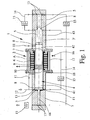
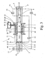
- the Fig. 1 . 3 and 5 show three different embodiments of a fluid working machine 1 according to the invention, wherein the figures are only simplified representations, so that only the essential components for the present invention are shown.
- the fluid working machines 1 shown in the figures serve to compress gases, in particular hydrogen, to a high pressure of, for example, 500 bar. Such fluid working machines 1 can therefore be used advantageously in particular for equipping hydrogen refueling stations.
- the in the Fig. 1 . 3 and 5 1 each have a linear motor 2 for driving a solid-state piston 4 movably arranged in a cylinder 3.
- a linear motor 2 for driving a solid-state piston 4 movably arranged in a cylinder 3.
- a translatory drive force is exerted on the solid-state piston 4, so that the solid-state piston 4 can move axially back and forth within the cylinder 3, 3 '.
- Within the cylinder 3 is at least one compression space 5, for the gas to be compressed, wherein the size of the compression space 5 changes depending on the position of the solid-state piston 4.
- the fluid working machine 1 is formed in a total of 4 stages, so that the compression of the gas takes place in four successive stages. Accordingly, in these two embodiments, four sections 41, 42, 43, 44, each having different diameters, are formed on the solid-body piston 4. Corresponding thereto, the cylinder 3, 3 'has four different sections with different inner diameters, so that a total of four compression chambers 5 are formed.
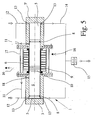
- the fluid working machine 1 according to Fig. 5 trained only one stage, but this is a double-acting fluid working machine 1, so that on Both sides of the solid-state piston 4 each have a compression space 5 is formed.
- linear motor 2 has a stator with a coil 9 and a rotor with a plurality of magnets 10, wherein the magnets 10 are arranged directly on the solid-state piston 4.
- the can 6 in the radial direction between the rotor, that is, the magnet 10 and the coil 9 of the stator arranged so that the can 6 not only the solid-state piston 4 but also the magnets 10 of the rotor encloses.
- the can 6 is thus between the stator and the rotor, so that the can 6 is penetrated by the magnetic field.
- the compression chamber 5 connected to the can 6 may also be connected directly to the fluid inlet side 12, d. H. the fluid inlet takes place in the compression space 5 connected to the can 6. If the fluid to be compressed has a low temperature, cooling of the linear motor 2 can take place at the same time.
- valves 13 which are arranged in the region of the individual compression chambers 5 and preferably formed as a plate valves.
- the fluid working machines 1 also four intake and exhaust valves 13, respectively.
- Fig. 1 and 3 is also indicated that the individual compression chambers 5 are connected to each other via lines 14, wherein in the individual lines 14 each have a heat exchanger 15 is provided for recooling the compressed gas.
- a coolant circuit 16 for cooling the coil 9 of the stator and thus for cooling the linear motor 2 has a total. The cooling takes place from the outside, that is, via a housing 9 surrounding the coil 9, so that the coil 9 does not come into direct contact with the coolant. Both for re-cooling of the compressed gas in the heat exchangers 15 and for cooling the linear motor 2 while the same coolant can be used.
- the illustrated embodiments of the fluid power machine 1 each have two cylinders 3; 3 ', wherein the linear motor 2 with the split tube 6 or the housing surrounding the linear motor 17 between the two cylinders 3, 3' is arranged.
- the sealing between the end faces of the two cylinders 3, 3 'and the corresponding end faces of the housing 17 takes place via static seals 18th
- the fluid working machines 1 shown in the figures are particularly suitable for compressing gases, preferably hydrogen, to high pressures of, for example, 1000 bar, so that such fluid working machines 1 are particularly suitable for equipping hydrogen refueling stations.
Description
Die Erfindung betrifft eine Fluidarbeitsmaschine zum Verdichten bzw. Fördern von Fluiden, insbesondere zum Verdichten von Gasen auf hohe Drücke, mit einem Linearmotor, mindestens einem Zylinder, einem in dem Zylinder axial bewegbaren Festkörperkolben, mindestens einem zwischen dem Zylinder und dem Festkörperkolben bzw. dem Flüssigkeitskolben ausgebildeten Kompressionsraum, und Ventilen für den Einlass und den Auslass des Fluids, die im Bereich des mindestens einen Kompressionsraums angeordnet sind, wobei der Linearmotor eine translatorische Antriebskraft auf den Festkörperkolben überträgt und der Festkörperkolben im Bereich des Linearmotors von einem fest angeordneten Spaltrohr umschlossen ist, so dass zwischen dem Festkörperkolben und dem Spaltrohr ein Zylinderinnenraum ausgebildet ist.The invention relates to a fluid working machine for compressing or conveying fluids, in particular for compressing gases to high pressures, with a linear motor, at least one cylinder, a solid-state piston axially movable in the cylinder, at least one between the cylinder and the solid-body piston or the liquid piston formed compression space, and valves for the inlet and the outlet of the fluid, which are arranged in the region of the at least one compression space, wherein the linear motor transmits a translational driving force to the solid-state piston and the solid-state piston is enclosed in the region of the linear motor of a fixed can, so in that a cylinder interior is formed between the solid-body piston and the can.
Fluidarbeitsmaschinen sind in verschiedenen Ausführungsformen und Varianten aus dem Stand der Technik bekannt. Die Fluidarbeitsmaschinen kann man dabei zunächst danach unterteilen, ob sie zum Fördern bzw. Verdichten von Flüssigkeiten oder von Gasen vorgesehen sind. Fluidarbeitsmaschinen, die zum Fördern von Flüssigkeiten eingesetzt werden, werden allgemein auch als Pumpen bezeichnet, während Fluidarbeitsmaschinen zum Verdichten von Gasen als Verdichter oder Kompressoren bezeichnet werden. Darüber hinaus können Fluidarbeitsmaschinen auch nach der Art der Antriebskraft - hydraulisch, elektrisch oder elektro-magnetisch - sowie nach der Art der Antriebsbewegung - rotatorisch oder translatorisch - unterschieden werden.Fluid power machines are known in various embodiments and variants of the prior art. The fluid working machines can be subdivided first according to whether they are provided for conveying or compressing liquids or gases. Fluid power machines used to convey fluids are also commonly referred to as pumps, while fluid power machines are referred to as compressors for compressing gases. In addition, fluid working machines can also be distinguished by the type of drive force - hydraulic, electric or electro-magnetic - as well as the type of drive movement - rotational or translational.
Die vorliegende Erfindung betrifft eine Fluidarbeitsmaschine, bei der die Antriebskraft von einem Linearmotor erzeugt wird, der auf einen in einem Zylinder geführten Kolben direkt, d. h. ohne Umwandlung einer Drehbewegung über eine Getriebe, eine translatorische Antriebskraft ausübt. Soll mit einer derartigen Fluidarbeitsmaschine ein Gas verdichtet werden, so kann die Maschine auch als Kolbenverdichter oder als Linearkompressor bezeichnet werden. Der Linearmotor besteht dabei im wesentlichen aus einem Stator bzw. Ständer und einem Läufer bzw. Aktuator, wobei der Linearmotor wie auch ein rotierender Motor als Asynchron- oder Synchron-Linearmotor ausgebildet sein kann. Der Linearmotor entspricht dann einem abgewickelten Asynchronmotor mit Kurzschlussläufer oder einem permanent erregten Synchron-Motor, wobei von der Spule bzw. Wicklung des Stators anstelle eines Drehfeldes ein Wanderfeld erzeugt wird. Die Kraftübertragung erfolgt wie bei Drehfeldmaschinen entweder durch Spannungsinduktion im Kurzschlussläufer des Asynchronmotors oder durch Interaktion mit dem Feld der Permanentmagnete des Synchronmotors.The present invention relates to a fluid working machine in which the driving force is generated by a linear motor which exerts a translational driving force on a piston guided in a cylinder directly, that is, without converting a rotational movement via a gear. If a gas is to be compressed with such a fluid working machine, then the machine can also be referred to as a piston compressor or as a linear compressor. The linear motor consists essentially of a stator or stator and a rotor or actuator, wherein the linear motor as well as a rotating motor may be formed as an asynchronous or synchronous linear motor. The linear motor then corresponds to a developed asynchronous motor with a squirrel-cage rotor or a permanently excited synchronous motor, wherein a traveling field is generated by the coil or winding of the stator instead of a rotating field. The power transmission takes place, as in induction machines, either by voltage induction in the squirrel-cage rotor of the asynchronous motor or by interaction with the field of the permanent magnets of the synchronous motor.
Aus der
Aus der
Die
Die
Die
Die
Eingangs ist ausgeführt, dass die Fluidarbeitsmaschine einem in dem Zylinder axial bewegbaren Festkörperkolben aufweist. Unter einem Festkörperkolben sollen dabei im Rahmen der Erfindung (übliche) feste bzw. massive (Metall-) Kolben verstanden werden, wie sie seit langem bekannt sind. Die zuvor beschriebenen Kompressoren weisen derartige Festkörperkolben auf.Initially, it is stated that the fluid working machine has a solid-state piston that is axially movable in the cylinder. In the context of the invention, a solid-state piston should be understood to mean (conventional) solid or solid (metal) pistons, as they have been known for a long time. The compressors described above have such solid-state pistons.
Eine Fluidarbeitsmaschine mit einem Flüssigkeitskolben ist beispielsweise aus der
Der vorliegenden Erfindung liegt die Aufgabe zugrunde, eine eingangs beschriebene Fluidarbeitsmaschine zum Verdichten bzw. Fördern von Fluiden zur Verfügung zu stellen, die bei möglichst einfachem Aufbau eine leckage- und möglichst auch schmiermittelfreie Verdichtung bzw. Förderung von Fluiden, insbesondere eine Verdichtung von Gasen auf hohe Drücke, ermöglicht.The present invention has for its object to provide an initially described fluid working machine for compressing or conveying fluids available, the simplest possible structure a leakage and possibly also lubricant-free compression or delivery of fluids, in particular a compression of gases to high Pressures, allows.
Diese Aufgabe ist bei der eingangs beschriebenen Fluidarbeitsmaschine mit den Merkmalen des Patentanspruchs 1 dadurch gelöst, dass der mit dem Spaltrohr verbundene Kompressionsraum über eine Leitung oder einen Kanal mit der Fluideintrittsseite verbunden ist, so dass der Druck in dem vom Spaltrohr umgebenden Zylinderinnenraum reduziert ist.This object is achieved in the above-described fluid work machine with the features of
Erfindungsgemäß ist der mit dem Spaltrohr verbundene Kompressionsraum über eine Leitung oder einen im Zylinder oder im Gehäuse ausgebildeten Kanal mit der Fluideintrittsseite, d. h. mit der Saugseite der Fluidarbeitsmaschine verbunden. Durch diese Maßnahme wird der Druck im Bereich des Spaltrohres auf den niedrigen Druck an der Fluideintrittsseite reduziert. Interne Leckagen, die entlang der bewegten Kolbenabdichtungen auftreten, werden auf den Saugdruck entspannt und an die Fluideintrittsseite abgeführt. Dadurch kann die erforderliche Wandstärke des Spaltrohres reduziert werden, wodurch sich bei einer Anordnung des Spaltrohres zwischen dem Läufer und der Spule des Stators die elektrischen Verluste verringern. Eine bei besonders hohen Drücken ansonsten erforderliche dick- oder doppelwandige Ausführung des Spaltrohres kann dadurch entfallen. Unabhängig davon ist jedoch zur Erhöhung der Sicherheit, insbesondere bei besonders gefährlichen Gasen (toxischen, umweltbelastenden oder radioaktiven Gasen) die Verwendung eines doppelwandigen Spaltrohres möglich.According to the invention, the compression chamber connected to the can is connected to the fluid inlet side via a conduit or a channel formed in the cylinder or in the housing. H. connected to the suction side of the fluid work machine. By this measure, the pressure in the region of the can is reduced to the low pressure at the fluid inlet side. Internal leaks that occur along the moving piston seals are released to the suction pressure and discharged to the fluid inlet side. As a result, the required wall thickness of the split tube can be reduced, thereby reducing the electrical losses in an arrangement of the can between the rotor and the coil of the stator. An otherwise required at particularly high pressures thick or double-walled design of the can can be eliminated. Irrespective of this, however, the use of a double-walled split tube is possible in order to increase safety, in particular in the case of particularly dangerous gases (toxic, polluting or radioactive gases).
Durch die Anordnung eines Spaltrohres kann auf einfache Art und Weise die Leckagefreiheit zur Atmosphäre erreicht werden. Die bei Abdichtung des Festkörperkolbens zum Antrieb und somit zur Atmosphäre an bewegten Dichtungen prinzipbedingt auftretenden Leckagen werden durch das Spaltrohr vermieden. Durch die Anordnung des Spaltrohres kann zur Atmosphäre ausschließlich mit statischen Dichtungen abgedichtet werden.The arrangement of a split tube can be achieved in a simple way, the freedom from leaks to the atmosphere. The leakage occurring when sealing the solid-state piston to the drive and thus to the atmosphere of moving seals due to the principle are avoided by the can. The arrangement of the split tube can be sealed to the atmosphere only with static seals.
Gemäß einer ersten vorteilhaften Ausgestaltung der Erfindung ist das Spaltrohr in radialer Richtung zwischen dem Läufer und der Spule des Stators angeordnet, so dass das Spaltrohr den Läufer umschließt. Bei dieser Ausführungsform befindet sich das Spaltrohr somit zwischen dem Stator und dem Läufer. Gemäß einer alternativen Ausgestaltung der Erfindung sind sowohl der Läufer als auch die Spule des Stators innerhalb des Spaltrohres angeordnet, so dass das Spaltrohr den Läufer und den Stator umschließt.According to a first advantageous embodiment of the invention, the can is arranged in the radial direction between the rotor and the coil of the stator, so that the can encloses the rotor. In this embodiment, the split tube is thus between the stator and the rotor. According to an alternative embodiment of the invention, both the rotor and the coil of the stator are arranged within the can, so that the can encloses the rotor and the stator.
Bei der ersten Ausführungsvariante dient das Spaltrohr somit als Trennwand zwischen dem elektrischen Antriebssystem und dem fluidberührten Kompressionsraum bzw. dem bewegten Festkörperkolben, wobei das Spaltrohr zur Energieübertragung vom Magnetfeld durchdrungen wird. Dadurch kommt es zu elektrischen Verlusten als Folge von Wirbelströmen im Spaltrohr sowie zu einer Erwärmung des Spaltrohres, so dass der Wirkungsgrad eines Linearmotors mit dazwischen angeordnetem Spaltrohr geringer ist als der Wirkungsgrad eines Linearmotors mit außen liegendem Spaltrohr. Dieser Nachteil der größeren Verluste tritt bei der zweiten Ausführungsvariante, bei der das Spaltrohr den Läufer und den Stator umschließt, nicht auf. Diese Ausführungsform ist somit - zumindest theoretisch - vorteilhaft, es sei denn, dass mit der Fluidarbeitsmaschine aggressive Medien verdichtet werden sollen. In diesem Fall wäre die Spule bei dem außen liegenden Spaltrohr ebenfalls dem aggressiven Medium ausgesetzt, was zu einer Beeinträchtigung der Lebensdauer der Spule fuhren kann.In the first embodiment, the can thus serves as a partition between the electric drive system and the fluid-contacting compression chamber or the moving solid-state piston, wherein the can is penetrated by the magnetic field for energy transfer. This leads to electrical losses as a result of eddy currents in the can and to a heating of the can, so that the efficiency of a linear motor with a gap tube arranged therebetween is lower than the efficiency of a linear motor with an outer gap tube. This disadvantage of greater losses does not occur in the second embodiment in which the can encloses the rotor and the stator. This embodiment is thus - at least theoretically - advantageous unless it is to be compacted with the fluid working machine aggressive media. In this case, the coil would also be exposed to the aggressive medium in the outer split tube, which can lead to an impairment of the life of the coil.
Die erfindungsgemäße Fluidarbeitsmaschine kann vorteilhafter Weise dadurch einfach aufgebaut sein, dass die Magnete des Läufers direkt auf dem Kolben angeordnet sind. Durch eine Befestigung der Magnete des Läufers direkt auf dem Kolben entfällt die Ausbildung und Anordnung eines separaten Magnetrahmens. Darüber hinaus können durch diese Ausgestaltung die radialen Abmessungen der Fluidarbeitsmaschine, insbesondere des Zylinders, verringert werden.The fluid working machine according to the invention can advantageously be constructed simply by arranging the magnets of the rotor directly on the piston. By attaching the magnets of the rotor directly on the piston eliminates the formation and arrangement of a separate magnetic frame. In addition, the radial dimensions of the fluid working machine, in particular of the cylinder can be reduced by this configuration.
Gemäß einer weiteren bevorzugten Ausgestaltung der Erfindung ist die Fluidarbeitsmaschine mehrstufig ausgebildet, d. h. die Verdichtung eines Gases erfolgt in mindestens zwei, vorzugsweise in vier Stufen. Alternativ dazu ist auch eine einstufige Verdichtung möglich, wobei dann vorzugsweise eine Ausgleichsstufe vorgesehen ist, um die für die Verdichtung notwenigen resultierenden Kräfte gering zu halten. Erfolgt die Verdichtung des Gases mehrstufig, so ist vorteilhafter vorgesehen, dass der Festkörperkolben mehrere Abschnitte mit unterschiedlichen Durchmessern aufweist. Der Kolben kann dabei herstellungstechnisch aus mehreren Kolbenabschnitten zusammengesetzt sein.According to a further preferred embodiment of the invention, the fluid working machine is designed in multiple stages, d. H. the compression of a gas takes place in at least two, preferably in four stages. Alternatively, a single-stage compression is possible, in which case preferably a compensation stage is provided in order to keep the resulting forces necessary for the compression low. If the compression of the gas in several stages, it is advantageously provided that the solid-state piston has a plurality of sections with different diameters. The piston can be composed manufacturing technology of several piston sections.
Zur Reduzierung von elektrischen Verlusten, die durch die Verwendung des Spaltrohres auftreten können, ist es darüber hinaus möglich, das Spaltrohr nicht aus Metall sondern aus einem Kunststoff oder aus Keramik herzustellen. Bei der Auswahl des Kunststoffes bzw. der Keramik muss dabei darauf geachtet werden, dass das Spaltrohr auch dem maximal auftretenden Druck sicher standhalten kann.To reduce electrical losses that may occur through the use of the can, it is also possible to make the can not made of metal but of a plastic or ceramic. When selecting the plastic or the ceramic care must be taken to ensure that the canned pipe can withstand the maximum occurring pressure safely.
Gemäß einer weiteren Ausgestaltung der Erfindung ist - wie im Stand der Technik grundsätzlich bekannt - mindestens ein Wärmetauscher zur Rückkühlung des Fluids vorgesehen. Bei einer mehrstufigen Fluidarbeitsmaschine ist dabei vorzugsweise nach jeder Verdichtungsstufe ein derartiger Wärmetauscher angeordnet. Das zur Rückkühlung eines Gases durch den Wärmetauscher benötigte Kühlmittel kann dann vorzugsweise auch zur Kühlung des Linearmotors verwendet werden. Die Kühlung erfolgt dabei vorzugsweise von außen, d. h. über ein den Linearmotor umgebendes Gehäuse, so dass weder der Läufer noch der Stator direkt mit dem Kühlmittel in Berührung kommt. Alternativ zur Verwendung eines separaten Kühlmittels kann sowohl zur Rückkühlung des Fluids als auch zur Kühlung des Linearmotors das Fluid selber verwendet werden, sofern dieses in einem entsprechend kaltem Zustand vorliegt. Handelt es sich bei dem zu verdichtenden Gas, beispielsweise um Wasserstoff, welches vor der Verdichtung tiefkalt in der Flüssigphase vorliegt, so kann das Gas in der Flüssigphase als Kühlmittel genutzt werden.According to a further embodiment of the invention is - as basically known in the art - at least one heat exchanger for recooling the fluid provided. In a multistage fluid working machine, such a heat exchanger is preferably arranged after each compression stage. The coolant required for the recooling of a gas through the heat exchanger can then preferably also be used for cooling the linear motor. The cooling is preferably carried out from the outside, d. H. via a housing surrounding the linear motor, so that neither the rotor nor the stator comes into direct contact with the coolant. As an alternative to the use of a separate coolant, the fluid itself can be used both for re-cooling the fluid and for cooling the linear motor, provided that this is present in a correspondingly cold state. If the gas to be compressed, for example hydrogen, is present in the liquid phase before deep-freezing, then the gas can be used as coolant in the liquid phase.
Die zuvor beschriebene erfindungsgemäße Fluidarbeitsmaschine eignet sich insbesondere zur Verdichtung von Gasen auf hohe Drücke, insbesondere zur Verdichtung von Wasserstoff auf 500 bar oder mehr. Damit eignet sich ein derartiger Linearkompressor insbesondere für die Ausrüstung von Wasserstofftankstellen.The above-described fluid working machine according to the invention is particularly suitable for the compression of gases to high pressures, in particular for the compression of hydrogen to 500 bar or more. Thus, such a linear compressor is particularly suitable for the equipment of hydrogen refueling stations.
Im einzelnen gibt es nun eine Vielzahl von Möglichkeiten, die erfindungsgemäße Fluidarbeitsmaschine auszugestalten und weiterzubilden. Dazu wird verwiesen auf die dem Patentanspruch 1 nachgeordneten Patentansprüche sowie auf die Beschreibung bevorzugter Ausführungsbeispiele in Verbindung mit der Zeichnung. In der Zeichnung zeigen
- Fig. 1
- ein erstes Ausführungsbeispiel einer erfindungsgemäßen Fluidarbeitsmaschine,
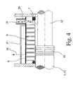
- Fig. 2
- eine vergrößerte Darstellung des Teilbereichs A der Fluidarbeitsmaschine gemäß
Fig. 1 , - Fig. 3
- ein zweites Ausführungsbeispiel einer erfindungsgemäßen Fluidarbeitsmaschine,
- Fig. 4
- eine vergrößerte Darstellung eines Teilbereichs der Fluidarbeitsmaschine gemäß
Fig. 3 , und - Fig. 5
- ein drittes Ausführungsbeispiel einer erfindungsgemäßen Fluidarbeitsmaschine.
- Fig. 1
- A first embodiment of a fluid working machine according to the invention,
- Fig. 2
- an enlarged view of the portion A of the fluid working machine according to
Fig. 1 . - Fig. 3
- A second embodiment of a fluid working machine according to the invention,
- Fig. 4
- an enlarged view of a portion of the fluid working machine according to
Fig. 3 , and - Fig. 5
- A third embodiment of a fluid working machine according to the invention.
Die
Die in den
Bei den beiden Ausführungsbeispielen gemäß den
Allen drei Ausführungsvarianten ist gemeinsam, dass der Festkörperkolben 4 im Bereich des Linearmotors 2 von einem fest angeordneten Spaltrohr 6 umschlossen ist. Durch die Anordnung des Spaltrohres 6 wird dabei eine sichere Abdichtung des Zylinderinnenraums 7 gewährleistet, so dass insgesamt die gewünschte Leckagefreiheit der Fluidarbeitsmaschine 1 auf einfache Art und Weise erreicht wird. Die Leckagefreiheit zur Atmosphäre muss dabei nicht mehr durch die an dem Festkörperkolben 4 angeordneten Kolbenabdichtungen 8 realisiert werden, die die Leckagefreiheit aufgrund ihrer Anordnung und Ausbildung als bewegte Dichtungen prinzipbedingt nicht bzw. nicht dauerhaft und insbesondere nicht schmiermittelfrei gewährleisten können. Die sonst übliche Durchführung der Kolbenstange zum Antrieb entfällt somit, ebenso die dafür erforderlichen bewegten Dichtsysteme. Die-Leckagefreiheit zur Atmosphäre wird somit ausschließlich mit statischen Dichtungen 18 gewährleistet.All three embodiments have in common that the solid-
Der in den
Bei dem Ausführungsbeispiel gemäß
In den
Alternativ dazu kann der mit dem Spaltrohr 6 verbundene Kompressionsraum 5 auch direkt mit der Fluideintrittsseite 12 verbunden sein, d. h. der Fluideintritt erfolgt in dem mit dem Spaltrohr 6 verbundene Kompressionsraum 5. Weist das zu verdichtende Fluid eine niedrige Temperatur auf, so kann dadurch gleichzeitig eine Kühlung des Linearmotors 2 erfolgen.Alternatively, the
Wie im Stand der Technik bekannt, erfolgt der Einlaß sowie der Auslaß des zu verdichtenden Gases über Ventile 13, die im Bereich der einzelnen Kompressionsräume 5 angeordnet und vorzugsweise als Plattenventile ausgebildet sind. Durch die anliegenden Differenzdrücke zwischen dem Kompressionsraum 5 und dem jeweiligen Ein- bzw. Auslaß erfolgt dann ein selbsttätiges Öffnen bzw. Schließen der Ventile 13. Da bei den beiden Ausführungsbeispielen gemäß den
In den
Schließlich ist aus den Figuren noch ersichtlich, dass die dargestellten Ausführungsbeispiele der Fluidarbeitsmaschine 1 jeweils zwei Zylinder 3; 3' aufweisen, wobei der Linearmotor 2 mit dem Spaltröhr 6 bzw. das den Linearmotor z umgebende Gehäuse 17 zwischen den beiden Zylindern 3, 3' angeordnet ist. Die Abdichtung zwischen den Stirnseiten der beiden Zylinder 3, 3' und den korrespondierenden Stirnseiten des Gehäuses 17 erfolgt dabei über statische Dichtungen 18.Finally, it is still apparent from the figures that the illustrated embodiments of the
Den
Die in den Figuren dargestellten Fluidarbeitsmaschinen 1 eignen sich insbesondere zur Verdichtung von Gasen, vorzugsweise von Wasserstoff, auf hohe Drücke von beispielsweise 1000 bar, so dass derartige Fluidarbeitsmaschinen 1 zur Ausrüstung von Wasserstofftankstellen besonders geeignet sind.The
Claims (9)
- Fluid working machine for compressing and/or conveying fluids, in particular for compressing gases to high pressures, having a linear motor (2), at least one cylinder (3), a solid piston (4) which can be moved axially in the cylinder (3), at least one compression space (5) which is formed between the cylinder (3) and the solid piston (4), and valves (13) for the entry and the exit of the fluid, which valves (13) are arranged in the region of the at least one compression space (5), wherein the linear motor (2) transfers a translational driving force to the solid piston (4), and the solid piston (4) being enclosed in the region of the linear motor (2) by a fixedly arranged split pipe (6), so that a cylinder interior space (7) is configured between the solid piston (4) and the split pipe (6),
characterized in
that the compression space which is connected to the split pipe (6) is connected via a line (11) or a duct to the fluid entry side (12), so that the pressure is reduced in the cylinder interior space (7) which is surrounded by the split pipe (6). - Fluid working machine according to Claim 1, the linear motor (2) having a stator and a rotor, characterized in that the split pipe (6) is arranged in the radial direction between the rotor and the coil (9) of the stator, so that the split pipe (6) encloses the rotor.
- Fluid working machine according to Claim 1, wherein the linear motor (2) having a stator and a rotor, characterized in that both the rotor and the coil (9) of the stator are arranged within the split pipe (6), so that the split pipe (6) encloses the rotor and the stator.
- Fluid working machine according to Claim 2 or 3, the rotor having magnets (10), characterized in that the magnets (10) of the rotor are arranged directly on the piston (4).
- Fluid working machine according to one of Claims 1 to 4, characterized in that the compression of a gas takes place in multiple stages.
- Fluid working machine according to Claim 5, characterized in that the solid piston (4) has a plurality of sections (41, 42, 43, 44) with different diameters.
- Fluid working machine according to one of Claims 1 to 6, characterized in that a coolant circuit (16) is provided for cooling the linear motor (2), in particular for cooling the coil (9) of the stator.
- Fluid working machine according to one of Claims 1 to 7, characterized in that at least one heat exchanger (15) is provided for re-cooling the fluid.
- Fluid working machine according to Claims 7 and 8, characterized in that the same coolant or the fluid to be compressed is used to cool the linear motor (2) and to recool the fluid..
Applications Claiming Priority (2)
| Application Number | Priority Date | Filing Date | Title |
|---|---|---|---|
| DE102006060147A DE102006060147B4 (en) | 2006-12-18 | 2006-12-18 | Fluid-working machine |
| PCT/EP2007/010872 WO2008074428A1 (en) | 2006-12-18 | 2007-12-12 | Fluid machine |
Publications (2)
| Publication Number | Publication Date |
|---|---|
| EP2122169A1 EP2122169A1 (en) | 2009-11-25 |
| EP2122169B1 true EP2122169B1 (en) | 2015-09-23 |
Family
ID=39124605
Family Applications (1)
| Application Number | Title | Priority Date | Filing Date |
|---|---|---|---|
| EP07856620.5A Active EP2122169B1 (en) | 2006-12-18 | 2007-12-12 | Fluid machine |
Country Status (5)
| Country | Link |
|---|---|
| US (1) | US20110052430A1 (en) |
| EP (1) | EP2122169B1 (en) |
| JP (2) | JP5431953B2 (en) |
| DE (1) | DE102006060147B4 (en) |
| WO (1) | WO2008074428A1 (en) |
Families Citing this family (27)
| Publication number | Priority date | Publication date | Assignee | Title |
|---|---|---|---|---|
| DE102008036528A1 (en) | 2008-08-06 | 2010-02-11 | Bentec Gmbh Drilling & Oilfield Systems | Method for operating a multi-pulse piston pump, multi-pulse piston pump and production of such |
| DE102008060659A1 (en) | 2008-12-08 | 2010-06-10 | Bentec Gmbh Drilling & Oilfield Systems | Clamping device for cylinder liners and their use and rinsing pump with clamping device |
| JP5377162B2 (en) * | 2009-08-28 | 2013-12-25 | 有限会社いどや | Electromagnetic pump and electromagnetic pump system using the same |
| US20110192573A1 (en) * | 2010-02-08 | 2011-08-11 | Harmel Defretin | System and method for moving a first fluid using a second fluid |
| DE102010053091A1 (en) * | 2010-12-01 | 2012-06-06 | Linde Aktiengesellschaft | Multi-stage piston compressor |
| DE102012008811A1 (en) | 2012-04-25 | 2013-10-31 | Bpg Beteiligungs Gmbh | Heat engine for driving linear generator utilized to produce electrical power in e.g. smaller industries, has cylinder units enabling supply of combustible gas into and discharging of combustion residues from chamber of cylinders |
| DE102012016222A1 (en) | 2012-08-01 | 2014-02-06 | Technische Universität Dresden | Cylinder-, piston- and valveless, continuously working fluid working machine for e.g. dosing liquid in chemical system during plastic production, has blocking region, where portions of liquids slide from region side to region opposite side |
| CN103670996B (en) * | 2012-09-14 | 2016-02-10 | 胜瑞兰工业设备(苏州)有限公司 | A kind of No leakage formula magnetic driving reciprocating pump |
| EP2725227B1 (en) * | 2012-10-24 | 2015-05-20 | Delphi International Operations Luxembourg S.à r.l. | Pump assembly |
| JP6087713B2 (en) | 2013-04-24 | 2017-03-01 | 株式会社神戸製鋼所 | Compression device |
| US11466678B2 (en) * | 2013-11-07 | 2022-10-11 | Gas Technology Institute | Free piston linear motor compressor and associated systems of operation |
| US10323628B2 (en) * | 2013-11-07 | 2019-06-18 | Gas Technology Institute | Free piston linear motor compressor and associated systems of operation |
| DE102013019499A1 (en) * | 2013-11-21 | 2015-05-21 | Linde Aktiengesellschaft | Piston compressor and method for compressing a cryogenic, gaseous medium, in particular hydrogen |
| JP6163646B2 (en) * | 2014-05-27 | 2017-07-19 | 株式会社国際電気通信基礎技術研究所 | Actuator device, humanoid robot and power assist device |
| JP6035590B2 (en) | 2014-05-27 | 2016-11-30 | 株式会社国際電気通信基礎技術研究所 | Actuator device, humanoid robot and power assist device |
| JP6276120B2 (en) * | 2014-06-27 | 2018-02-07 | 株式会社神戸製鋼所 | Gas compressor |
| DE102014012977A1 (en) * | 2014-09-08 | 2016-03-10 | Albonair Gmbh | Reducing agent metering system with improved delivery pump |
| JP6276154B2 (en) * | 2014-09-26 | 2018-02-07 | 株式会社神戸製鋼所 | Reciprocating compressor |
| JP2016213314A (en) * | 2015-05-08 | 2016-12-15 | 富士通株式会社 | Cooling module and electronic device |
| DE102015209728A1 (en) | 2015-05-27 | 2016-12-01 | Robert Bosch Gmbh | Pump device, brake system |
| CN105443977B (en) * | 2015-12-28 | 2017-12-26 | 重庆耐德能源装备集成有限公司 | Natural gas inner-cooled hydraulic booster container |
| US11118578B2 (en) * | 2017-02-15 | 2021-09-14 | Extiel Holdings, Llc | Internally cooled inline drive compressor |
| CN107605691B (en) * | 2017-09-08 | 2019-04-02 | 中国神华能源股份有限公司 | Linear drives plunger pump, linear drives emulsion pump system and control method |
| PL240516B1 (en) * | 2018-01-09 | 2022-04-19 | Dobrianski Jurij | Steam engine |
| BE1026883B1 (en) * | 2018-12-18 | 2020-07-22 | Atlas Copco Airpower Nv | Piston compressor and method in which such a reciprocating compressor is used |
| BE1026881B1 (en) * | 2018-12-18 | 2020-07-22 | Atlas Copco Airpower Nv | Piston compressor |
| JP7330088B2 (en) * | 2019-12-16 | 2023-08-21 | 株式会社東芝 | Liquid piston device and liquid piston operating method |
Family Cites Families (19)
| Publication number | Priority date | Publication date | Assignee | Title |
|---|---|---|---|---|
| US3196797A (en) * | 1961-09-18 | 1965-07-27 | Mario Pagano S P A | Dynamic thrust electromagnetic compressor, particularly suitable for compressing liquid or gaseous substances |
| DE2937157C2 (en) * | 1979-09-13 | 1982-06-16 | Franz Klaus Union Armaturen, Pumpen Gmbh & Co, 4630 Bochum | Piston displacement pumps, in particular metering pumps |
| US4496287A (en) * | 1980-02-14 | 1985-01-29 | Robert M. Nelson | Sensors for detection of fluid condition, and control systems utilizing their signals |
| NL8204005A (en) * | 1982-10-18 | 1984-05-16 | Philips Nv | COOLING SYSTEM WITH TWO-STAGE COMPRESSION DEVICE. |
| JPS60125371U (en) * | 1984-02-03 | 1985-08-23 | 三菱重工業株式会社 | positive displacement pump or blower |
| US4815949A (en) * | 1985-06-24 | 1989-03-28 | Rabson Thomas A | In-well submersible motor with stacked component stator |
| US5354185A (en) * | 1992-10-05 | 1994-10-11 | Aura Systems, Inc. | Electromagnetically actuated reciprocating compressor driver |
| EP1020013B1 (en) * | 1997-10-04 | 2004-04-28 | Z & D Limited | Linear motor compressor |
| DE19846711C2 (en) * | 1998-10-09 | 2003-05-08 | Trumpf Sachsen Gmbh | High pressure pump with linear motor drive |
| US6183206B1 (en) * | 1999-05-10 | 2001-02-06 | The United States Of America As Represented By The Secretary Of The Air Force | Magnetohydrodynamically-driven compressor |
| DE10149506A1 (en) * | 2001-10-06 | 2003-04-10 | Leybold Vakuum Gmbh | Oscillatory piston drive for vacuum pump uses electromagnetic coils cooperating with drive magnet between two sections of vacuum pump piston |
| DE10214047A1 (en) * | 2002-03-28 | 2003-10-09 | Volkswagen Ag | Compressor for a motor vehicle air-conditioning facility has a closed carbon dioxide coolant circuit, a housing as a compression area with a to-and-fro-stroke piston and inlet/outlet valves. |
| DE10314007A1 (en) * | 2003-03-28 | 2004-10-07 | Leybold Vakuum Gmbh | Piston vacuum pump for pumping gas, has sensor that detects speed of switching supply of energizing current between electrical coils by magnet arrangement |
| JP2005307796A (en) * | 2004-04-20 | 2005-11-04 | Matsushita Electric Ind Co Ltd | Linear compressor |
| JP2005351255A (en) * | 2004-06-10 | 2005-12-22 | Kaken Geneqs:Kk | Reciprocating compressor |
| DE102004046316A1 (en) * | 2004-09-24 | 2006-03-30 | Linde Ag | Method and apparatus for compressing a gaseous medium |
| KR100613514B1 (en) * | 2004-10-07 | 2006-08-17 | 엘지전자 주식회사 | Structure of Discharge part for linear compressor |
| DE102004055924B4 (en) * | 2004-11-19 | 2011-08-18 | Lg Electronics Inc., Seoul | Linear compressor, has magnet frame transmitting linear movement of magnet to piston, and cooling pipe disposed in contact with bobbin, where cooling fluid supply unit supplies cooling fluid into pipe |
| EP1785625A3 (en) * | 2005-11-10 | 2009-11-25 | LG Electronics Inc. | Linear Compressor |
-
2006
- 2006-12-18 DE DE102006060147A patent/DE102006060147B4/en not_active Expired - Fee Related
-
2007
- 2007-12-12 WO PCT/EP2007/010872 patent/WO2008074428A1/en active Application Filing
- 2007-12-12 US US12/519,919 patent/US20110052430A1/en not_active Abandoned
- 2007-12-12 EP EP07856620.5A patent/EP2122169B1/en active Active
- 2007-12-12 JP JP2009541843A patent/JP5431953B2/en active Active
-
2013
- 2013-12-05 JP JP2013252239A patent/JP5868382B2/en active Active
Also Published As
| Publication number | Publication date |
|---|---|
| JP5431953B2 (en) | 2014-03-05 |
| WO2008074428A1 (en) | 2008-06-26 |
| US20110052430A1 (en) | 2011-03-03 |
| JP5868382B2 (en) | 2016-02-24 |
| DE102006060147B4 (en) | 2009-05-14 |
| JP2010513779A (en) | 2010-04-30 |
| JP2014090663A (en) | 2014-05-15 |
| EP2122169A1 (en) | 2009-11-25 |
| DE102006060147A1 (en) | 2008-06-19 |
Similar Documents
| Publication | Publication Date | Title |
|---|---|---|
| EP2122169B1 (en) | Fluid machine | |
| EP1999375B1 (en) | Compressor unit | |
| EP1069313B1 (en) | Turbo compressor | |
| DE112010003623B4 (en) | STORAGE SYSTEM FOR FREE-PISTON STIRLING MACHINES | |
| EP1574714B1 (en) | Pump unit | |
| EP1963674B1 (en) | Water-cooled piston compressor | |
| EP0149219A2 (en) | Piston pump | |
| DE102012202460A1 (en) | Electromotive gear device with one-piece housing | |
| EP3480929B1 (en) | Cooled housing for the stator of a direct drive | |
| WO2007110275A1 (en) | Compressor unit | |
| EP3523537B1 (en) | Semi-hermetic coolant compressor | |
| EP1979622A1 (en) | Compressor unit | |
| DE102010064061A1 (en) | Turbo compressor for fuel cell drive of internal combustion engine of hybrid drive for motor vehicle, has drive unit and two compressor wheels driven by drive unit | |
| WO2008046817A1 (en) | Encapsulated electrical machine with liquid-cooled stator | |
| DE102018205269B4 (en) | screw compressor | |
| DE10342421A1 (en) | Plunger compressor for refrigerants | |
| WO2013017669A1 (en) | Compressor device and cooling device fitted therewith and cooler unit fitted therewith | |
| WO2008019815A1 (en) | Rotor cooling for dry-running twin-shaft vacuum pumps or compressors | |
| WO2010084002A2 (en) | Hydraulic machine assembly | |
| EP2795204B1 (en) | Compressor | |
| DE102010015932B4 (en) | Solenoid valve for flow control | |
| DE102018206401A1 (en) | Electric motor and method for producing the same | |
| DE102018203264A1 (en) | Hydraulic actuator | |
| DE102021102648B4 (en) | Piston compressor, in particular for a heat pump | |
| DE102011080377A1 (en) | Compressor device for e.g. compressor refrigerating machine for refrigerator, has compressor unit for compressing helium, and electrical hydrostatic drive unit magnetically or mechanically coupled with compressor element |
Legal Events
| Date | Code | Title | Description |
|---|---|---|---|
| PUAI | Public reference made under article 153(3) epc to a published international application that has entered the european phase |
Free format text: ORIGINAL CODE: 0009012 |
|
| 17P | Request for examination filed |
Effective date: 20090715 |
|
| AK | Designated contracting states |
Kind code of ref document: A1 Designated state(s): AT BE BG CH CY CZ DE DK EE ES FI FR GB GR HU IE IS IT LI LT LU LV MC MT NL PL PT RO SE SI SK TR |
|
| DAX | Request for extension of the european patent (deleted) | ||
| 17Q | First examination report despatched |
Effective date: 20100301 |
|
| GRAP | Despatch of communication of intention to grant a patent |
Free format text: ORIGINAL CODE: EPIDOSNIGR1 |
|
| INTG | Intention to grant announced |
Effective date: 20150330 |
|
| GRAS | Grant fee paid |
Free format text: ORIGINAL CODE: EPIDOSNIGR3 |
|
| GRAA | (expected) grant |
Free format text: ORIGINAL CODE: 0009210 |
|
| AK | Designated contracting states |
Kind code of ref document: B1 Designated state(s): AT BE BG CH CY CZ DE DK EE ES FI FR GB GR HU IE IS IT LI LT LU LV MC MT NL PL PT RO SE SI SK TR |
|
| REG | Reference to a national code |
Ref country code: GB Ref legal event code: FG4D Free format text: NOT ENGLISH |
|
| REG | Reference to a national code |
Ref country code: CH Ref legal event code: EP |
|
| REG | Reference to a national code |
Ref country code: AT Ref legal event code: REF Ref document number: 751404 Country of ref document: AT Kind code of ref document: T Effective date: 20151015 |
|
| REG | Reference to a national code |
Ref country code: IE Ref legal event code: FG4D Free format text: LANGUAGE OF EP DOCUMENT: GERMAN |
|
| REG | Reference to a national code |
Ref country code: DE Ref legal event code: R096 Ref document number: 502007014253 Country of ref document: DE |
|
| REG | Reference to a national code |
Ref country code: FR Ref legal event code: PLFP Year of fee payment: 9 |
|
| PG25 | Lapsed in a contracting state [announced via postgrant information from national office to epo] |
Ref country code: LT Free format text: LAPSE BECAUSE OF FAILURE TO SUBMIT A TRANSLATION OF THE DESCRIPTION OR TO PAY THE FEE WITHIN THE PRESCRIBED TIME-LIMIT Effective date: 20150923 Ref country code: GR Free format text: LAPSE BECAUSE OF FAILURE TO SUBMIT A TRANSLATION OF THE DESCRIPTION OR TO PAY THE FEE WITHIN THE PRESCRIBED TIME-LIMIT Effective date: 20151224 Ref country code: LV Free format text: LAPSE BECAUSE OF FAILURE TO SUBMIT A TRANSLATION OF THE DESCRIPTION OR TO PAY THE FEE WITHIN THE PRESCRIBED TIME-LIMIT Effective date: 20150923 Ref country code: FI Free format text: LAPSE BECAUSE OF FAILURE TO SUBMIT A TRANSLATION OF THE DESCRIPTION OR TO PAY THE FEE WITHIN THE PRESCRIBED TIME-LIMIT Effective date: 20150923 |
|
| REG | Reference to a national code |
Ref country code: LT Ref legal event code: MG4D |
|
| REG | Reference to a national code |
Ref country code: NL Ref legal event code: FP |
|
| PG25 | Lapsed in a contracting state [announced via postgrant information from national office to epo] |
Ref country code: SE Free format text: LAPSE BECAUSE OF FAILURE TO SUBMIT A TRANSLATION OF THE DESCRIPTION OR TO PAY THE FEE WITHIN THE PRESCRIBED TIME-LIMIT Effective date: 20150923 |
|
| PG25 | Lapsed in a contracting state [announced via postgrant information from national office to epo] |
Ref country code: SK Free format text: LAPSE BECAUSE OF FAILURE TO SUBMIT A TRANSLATION OF THE DESCRIPTION OR TO PAY THE FEE WITHIN THE PRESCRIBED TIME-LIMIT Effective date: 20150923 Ref country code: CZ Free format text: LAPSE BECAUSE OF FAILURE TO SUBMIT A TRANSLATION OF THE DESCRIPTION OR TO PAY THE FEE WITHIN THE PRESCRIBED TIME-LIMIT Effective date: 20150923 Ref country code: IS Free format text: LAPSE BECAUSE OF FAILURE TO SUBMIT A TRANSLATION OF THE DESCRIPTION OR TO PAY THE FEE WITHIN THE PRESCRIBED TIME-LIMIT Effective date: 20160123 Ref country code: EE Free format text: LAPSE BECAUSE OF FAILURE TO SUBMIT A TRANSLATION OF THE DESCRIPTION OR TO PAY THE FEE WITHIN THE PRESCRIBED TIME-LIMIT Effective date: 20150923 Ref country code: ES Free format text: LAPSE BECAUSE OF FAILURE TO SUBMIT A TRANSLATION OF THE DESCRIPTION OR TO PAY THE FEE WITHIN THE PRESCRIBED TIME-LIMIT Effective date: 20150923 |
|
| PG25 | Lapsed in a contracting state [announced via postgrant information from national office to epo] |
Ref country code: RO Free format text: LAPSE BECAUSE OF FAILURE TO SUBMIT A TRANSLATION OF THE DESCRIPTION OR TO PAY THE FEE WITHIN THE PRESCRIBED TIME-LIMIT Effective date: 20150923 Ref country code: PL Free format text: LAPSE BECAUSE OF FAILURE TO SUBMIT A TRANSLATION OF THE DESCRIPTION OR TO PAY THE FEE WITHIN THE PRESCRIBED TIME-LIMIT Effective date: 20150923 Ref country code: BE Free format text: LAPSE BECAUSE OF NON-PAYMENT OF DUE FEES Effective date: 20151231 Ref country code: PT Free format text: LAPSE BECAUSE OF FAILURE TO SUBMIT A TRANSLATION OF THE DESCRIPTION OR TO PAY THE FEE WITHIN THE PRESCRIBED TIME-LIMIT Effective date: 20160125 |
|
| REG | Reference to a national code |
Ref country code: DE Ref legal event code: R097 Ref document number: 502007014253 Country of ref document: DE |
|
| PG25 | Lapsed in a contracting state [announced via postgrant information from national office to epo] |
Ref country code: LU Free format text: LAPSE BECAUSE OF FAILURE TO SUBMIT A TRANSLATION OF THE DESCRIPTION OR TO PAY THE FEE WITHIN THE PRESCRIBED TIME-LIMIT Effective date: 20151212 Ref country code: MC Free format text: LAPSE BECAUSE OF FAILURE TO SUBMIT A TRANSLATION OF THE DESCRIPTION OR TO PAY THE FEE WITHIN THE PRESCRIBED TIME-LIMIT Effective date: 20150923 |
|
| PLBE | No opposition filed within time limit |
Free format text: ORIGINAL CODE: 0009261 |
|
| STAA | Information on the status of an ep patent application or granted ep patent |
Free format text: STATUS: NO OPPOSITION FILED WITHIN TIME LIMIT |
|
| GBPC | Gb: european patent ceased through non-payment of renewal fee |
Effective date: 20151223 |
|
| 26N | No opposition filed |
Effective date: 20160624 |
|
| PG25 | Lapsed in a contracting state [announced via postgrant information from national office to epo] |
Ref country code: DK Free format text: LAPSE BECAUSE OF FAILURE TO SUBMIT A TRANSLATION OF THE DESCRIPTION OR TO PAY THE FEE WITHIN THE PRESCRIBED TIME-LIMIT Effective date: 20150923 |
|
| REG | Reference to a national code |
Ref country code: IE Ref legal event code: MM4A |
|
| PG25 | Lapsed in a contracting state [announced via postgrant information from national office to epo] |
Ref country code: GB Free format text: LAPSE BECAUSE OF NON-PAYMENT OF DUE FEES Effective date: 20151223 Ref country code: IE Free format text: LAPSE BECAUSE OF NON-PAYMENT OF DUE FEES Effective date: 20151212 |
|
| PG25 | Lapsed in a contracting state [announced via postgrant information from national office to epo] |
Ref country code: SI Free format text: LAPSE BECAUSE OF FAILURE TO SUBMIT A TRANSLATION OF THE DESCRIPTION OR TO PAY THE FEE WITHIN THE PRESCRIBED TIME-LIMIT Effective date: 20150923 |
|
| REG | Reference to a national code |
Ref country code: FR Ref legal event code: PLFP Year of fee payment: 10 |
|
| PG25 | Lapsed in a contracting state [announced via postgrant information from national office to epo] |
Ref country code: HU Free format text: LAPSE BECAUSE OF FAILURE TO SUBMIT A TRANSLATION OF THE DESCRIPTION OR TO PAY THE FEE WITHIN THE PRESCRIBED TIME-LIMIT; INVALID AB INITIO Effective date: 20071212 Ref country code: BG Free format text: LAPSE BECAUSE OF FAILURE TO SUBMIT A TRANSLATION OF THE DESCRIPTION OR TO PAY THE FEE WITHIN THE PRESCRIBED TIME-LIMIT Effective date: 20150923 |
|
| PG25 | Lapsed in a contracting state [announced via postgrant information from national office to epo] |
Ref country code: CY Free format text: LAPSE BECAUSE OF FAILURE TO SUBMIT A TRANSLATION OF THE DESCRIPTION OR TO PAY THE FEE WITHIN THE PRESCRIBED TIME-LIMIT Effective date: 20150923 |
|
| PG25 | Lapsed in a contracting state [announced via postgrant information from national office to epo] |
Ref country code: MT Free format text: LAPSE BECAUSE OF FAILURE TO SUBMIT A TRANSLATION OF THE DESCRIPTION OR TO PAY THE FEE WITHIN THE PRESCRIBED TIME-LIMIT Effective date: 20150923 Ref country code: TR Free format text: LAPSE BECAUSE OF FAILURE TO SUBMIT A TRANSLATION OF THE DESCRIPTION OR TO PAY THE FEE WITHIN THE PRESCRIBED TIME-LIMIT Effective date: 20150923 |
|
| REG | Reference to a national code |
Ref country code: FR Ref legal event code: PLFP Year of fee payment: 11 |
|
| PGFP | Annual fee paid to national office [announced via postgrant information from national office to epo] |
Ref country code: CH Payment date: 20230103 Year of fee payment: 16 |
|
| PGFP | Annual fee paid to national office [announced via postgrant information from national office to epo] |
Ref country code: NL Payment date: 20231220 Year of fee payment: 17 Ref country code: IT Payment date: 20231228 Year of fee payment: 17 Ref country code: FR Payment date: 20231221 Year of fee payment: 17 Ref country code: AT Payment date: 20231221 Year of fee payment: 17 |
|
| PGFP | Annual fee paid to national office [announced via postgrant information from national office to epo] |
Ref country code: DE Payment date: 20240222 Year of fee payment: 17 Ref country code: CH Payment date: 20240101 Year of fee payment: 17 |