EP2120652B1 - Device for producing hot water or water vapour especially for vehicles, especially motor vehicles - Google Patents
Device for producing hot water or water vapour especially for vehicles, especially motor vehicles Download PDFInfo
- Publication number
- EP2120652B1 EP2120652B1 EP08707456A EP08707456A EP2120652B1 EP 2120652 B1 EP2120652 B1 EP 2120652B1 EP 08707456 A EP08707456 A EP 08707456A EP 08707456 A EP08707456 A EP 08707456A EP 2120652 B1 EP2120652 B1 EP 2120652B1
- Authority
- EP
- European Patent Office
- Prior art keywords
- water
- hot
- steam
- tapping
- tap
- Prior art date
- Legal status (The legal status is an assumption and is not a legal conclusion. Google has not performed a legal analysis and makes no representation as to the accuracy of the status listed.)
- Active
Links
- XLYOFNOQVPJJNP-UHFFFAOYSA-N water Substances O XLYOFNOQVPJJNP-UHFFFAOYSA-N 0.000 title claims abstract description 209
- 238000010079 rubber tapping Methods 0.000 claims abstract description 84
- 230000035622 drinking Effects 0.000 claims description 72
- 238000002360 preparation method Methods 0.000 claims description 38
- 230000008878 coupling Effects 0.000 claims description 11
- 238000010168 coupling process Methods 0.000 claims description 11
- 238000005859 coupling reaction Methods 0.000 claims description 11
- 238000010438 heat treatment Methods 0.000 abstract description 18
- 241000723377 Coffea Species 0.000 description 92
- 235000013353 coffee beverage Nutrition 0.000 description 92
- 238000000605 extraction Methods 0.000 description 88
- 238000013461 design Methods 0.000 description 25
- 239000000284 extract Substances 0.000 description 22
- 238000004519 manufacturing process Methods 0.000 description 12
- 238000003860 storage Methods 0.000 description 11
- 238000000034 method Methods 0.000 description 10
- 230000008569 process Effects 0.000 description 10
- 239000002775 capsule Substances 0.000 description 8
- 238000006073 displacement reaction Methods 0.000 description 8
- 244000269722 Thea sinensis Species 0.000 description 7
- 239000007788 liquid Substances 0.000 description 7
- 230000008901 benefit Effects 0.000 description 6
- 238000004140 cleaning Methods 0.000 description 6
- 239000000843 powder Substances 0.000 description 6
- 238000007789 sealing Methods 0.000 description 6
- 238000005520 cutting process Methods 0.000 description 5
- 241001572165 Coffea benghalensis Species 0.000 description 4
- 238000010276 construction Methods 0.000 description 4
- 230000009977 dual effect Effects 0.000 description 4
- 235000015114 espresso Nutrition 0.000 description 4
- 239000008187 granular material Substances 0.000 description 4
- 230000010354 integration Effects 0.000 description 4
- 230000003287 optical effect Effects 0.000 description 3
- 235000013361 beverage Nutrition 0.000 description 2
- 238000004891 communication Methods 0.000 description 2
- 150000001875 compounds Chemical class 0.000 description 2
- 238000011109 contamination Methods 0.000 description 2
- 238000011161 development Methods 0.000 description 2
- 230000018109 developmental process Effects 0.000 description 2
- 230000000694 effects Effects 0.000 description 2
- 239000013536 elastomeric material Substances 0.000 description 2
- 210000003746 feather Anatomy 0.000 description 2
- 239000012530 fluid Substances 0.000 description 2
- 235000012171 hot beverage Nutrition 0.000 description 2
- 239000000463 material Substances 0.000 description 2
- 239000008267 milk Substances 0.000 description 2
- 210000004080 milk Anatomy 0.000 description 2
- 235000013336 milk Nutrition 0.000 description 2
- 238000003825 pressing Methods 0.000 description 2
- 230000001681 protective effect Effects 0.000 description 2
- 239000000126 substance Substances 0.000 description 2
- 244000236521 Bupleurum rotundifolium Species 0.000 description 1
- 229920000742 Cotton Polymers 0.000 description 1
- 240000003085 Quassia amara Species 0.000 description 1
- 230000004913 activation Effects 0.000 description 1
- 239000000853 adhesive Substances 0.000 description 1
- 230000001070 adhesive effect Effects 0.000 description 1
- XAGFODPZIPBFFR-UHFFFAOYSA-N aluminium Chemical compound [Al] XAGFODPZIPBFFR-UHFFFAOYSA-N 0.000 description 1
- 229910052782 aluminium Inorganic materials 0.000 description 1
- 235000019568 aromas Nutrition 0.000 description 1
- 230000000903 blocking effect Effects 0.000 description 1
- 238000009835 boiling Methods 0.000 description 1
- 238000013124 brewing process Methods 0.000 description 1
- 230000008859 change Effects 0.000 description 1
- 239000003795 chemical substances by application Substances 0.000 description 1
- 230000001419 dependent effect Effects 0.000 description 1
- 239000000645 desinfectant Substances 0.000 description 1
- 238000010586 diagram Methods 0.000 description 1
- 238000004090 dissolution Methods 0.000 description 1
- 238000009826 distribution Methods 0.000 description 1
- 238000005516 engineering process Methods 0.000 description 1
- 230000002349 favourable effect Effects 0.000 description 1
- 239000000945 filler Substances 0.000 description 1
- 239000000796 flavoring agent Substances 0.000 description 1
- 235000019634 flavors Nutrition 0.000 description 1
- 239000003205 fragrance Substances 0.000 description 1
- 239000013505 freshwater Substances 0.000 description 1
- 238000001802 infusion Methods 0.000 description 1
- 238000003780 insertion Methods 0.000 description 1
- 230000037431 insertion Effects 0.000 description 1
- 238000009434 installation Methods 0.000 description 1
- 239000011810 insulating material Substances 0.000 description 1
- 230000007246 mechanism Effects 0.000 description 1
- 239000012528 membrane Substances 0.000 description 1
- 239000000203 mixture Substances 0.000 description 1
- 230000002093 peripheral effect Effects 0.000 description 1
- 238000012545 processing Methods 0.000 description 1
- 230000008439 repair process Effects 0.000 description 1
- 230000007306 turnover Effects 0.000 description 1
- 238000011144 upstream manufacturing Methods 0.000 description 1
- 238000013022 venting Methods 0.000 description 1
- 239000002699 waste material Substances 0.000 description 1
Images


Classifications
-
- A—HUMAN NECESSITIES
- A47—FURNITURE; DOMESTIC ARTICLES OR APPLIANCES; COFFEE MILLS; SPICE MILLS; SUCTION CLEANERS IN GENERAL
- A47J—KITCHEN EQUIPMENT; COFFEE MILLS; SPICE MILLS; APPARATUS FOR MAKING BEVERAGES
- A47J31/00—Apparatus for making beverages
- A47J31/005—Portable or compact beverage making apparatus, e.g. for travelling, for use in automotive vehicles
-
- A—HUMAN NECESSITIES
- A47—FURNITURE; DOMESTIC ARTICLES OR APPLIANCES; COFFEE MILLS; SPICE MILLS; SUCTION CLEANERS IN GENERAL
- A47J—KITCHEN EQUIPMENT; COFFEE MILLS; SPICE MILLS; APPARATUS FOR MAKING BEVERAGES
- A47J31/00—Apparatus for making beverages
- A47J31/44—Parts or details or accessories of beverage-making apparatus
- A47J31/54—Water boiling vessels in beverage making machines
-
- B—PERFORMING OPERATIONS; TRANSPORTING
- B60—VEHICLES IN GENERAL
- B60N—SEATS SPECIALLY ADAPTED FOR VEHICLES; VEHICLE PASSENGER ACCOMMODATION NOT OTHERWISE PROVIDED FOR
- B60N3/00—Arrangements or adaptations of other passenger fittings, not otherwise provided for
- B60N3/18—Arrangements or adaptations of other passenger fittings, not otherwise provided for of drinking-water or other beverage dispensing devices
Definitions
- the invention relates to an arrangement of a device for hot water or steam generation according to the preamble of claim 1.
- hot water generation devices is already known in vehicles in connection with the production of infusion beverages, such as coffee. So it is for example from the DE 103 47 047 A1 known to arrange a water tank together with the pump and heater in a trunk of a motor vehicle, so that from there heated water via a corresponding supply line to a brewing unit, which is arranged in the passenger compartment, can be supplied. In this brewing coffee or tea tabs can be inserted, which are then flowed through by the heated water to provide coffee or tea available, which is then performed as an extract via a further feed line to a cup holder on a cup, where it drips in the usual way from above into the cup.
- the cup holder is here part of a residual container, can be disposed of in the extra residues or other waste.
- a similar hot beverage preparation device is also known from DE 10 2004 016 194 A1 known.
- a H doublingeraufwer which can be connected for installation in a motor vehicle to a 12 or 24 volt DC power source of the vehicle.
- a low-voltage boiler is provided, in which with one or two 12-volt elements about 3.5 dl of water can be heated.
- This amount of hot water should be sufficient to be able to deliver one to two portions of hot water within a very short time in a vessel.
- the control of the amount of water via a pump and a valve.
- a fresh water reservoir is a commercial PET bottle, on the standard spout opening a connection valve is screwed.
- a reservoir for a coffee granules is a commercial coffee powder.
- the aroma closure of the can is broken during the insertion of the can on the connecting piece through the arranged in this neck opener.
- a cup or a cup, in which the coffee granules and / or the hot water is filled, is held by a bracket under a tap, so that here drips the hot water from above into the cup or in the cup.
- a similar principle with a faucet in which the liquid drips from above into a container parked or held behind it, also shows the EP 0 156 719 A1 , the GB 1,417,467 B and the US 4,057,892 B ,
- a device for processing hot drinks for a motor vehicle in which a mobile container an espresso machine is housed, which is operable through an opening on top of the container.
- the container has the shape of a cuboid and is made of a stable plastic, wherein fixing devices are arranged on the bottom side, which serve to hold the container in the passenger compartment, wherein the container can be moved to different positions along a rail arranged on the vehicle floor. Through an opening on the top of the container, the espresso machine can be positively inserted into the container.
- a similar construction in connection with a hot water heater is also from the DE 198 16 031 A1 known.
- a boiling water-preparing water heater which has a mixer tap with swivel spout, an overflow pipe, a water level indicator, a cleaning port, a dip tube and a connecting line.
- the filled amount of water is brought to a boil.
- the hot water is withdrawn through the overflow pipe.
- the mixer tap with swivel spout the removal of the heated water takes place.
- the dip tube is open and the overflow tube is closed.
- the filter device is a filter and a beverage receptacle, which is arranged on a hot plate.
- the filter device also has in addition to a level indicator on an outlet tap and an electrical outlet.
- Devices for hot water production or coffee machines are also also from the WO 01/72187 A1 , of the GB 2394215 A and the FR 2 506 592 A known.
- an arrangement of a device for hot water or steam generation in a wall region having vehicle or building interior wherein the device has at least one water reservoir and at least one heater, can be heated by the water to a predetermined temperature.
- the device further comprises at least one tap for a particular batch-wise tapping of water and / or steam, which, in particular optionally also for tap operation and / or to release a predetermined amount of water or steam, can be coupled or connected to a tap connection element.
- the at least one tap in the manner of a connection coupling or in the manner of a steam or water outlet in a wall region of the vehicle or building interior opens and is formed by a type of valve element or includes such, wherein the valve element in a valve actuation Water or steam in the desired amount, in particular also releases batchwise.
- a valve element is understood in the most general sense as a mechanical, electronic or manually operable or controlled and lockable inlet, outlet or passage device for steam or water.
- Such a mechanically and / or electronically actuated valve element is simple and inexpensive to manufacture and also reliable in operation.
- the preferably substantially the tapping forming valve element also advantageously has a closable in a valve rest position by means of a shut-off valve and valve actuation by means of the shut-off valve element flow channel, which is preferably performed itself or with a secondary connection channel to the heater and with this directly or indirectly connected flow is.
- the at least one tapping point opens on a vehicle-side wall region, preferably on a vehicle-side interior wall region.
- the tapping point opens in the manner of a steam or water outlet, in particular substantially flush with the surface in a vehicle-side wall area, preferably in a vehicle-side interior wall area.
- Such a tap can at various points of a z. B. vehicle, in particular a vehicle interior are arranged, for. B. in storage space, such as the trunk.
- an arrangement of such a tap in a passenger compartment is preferred as the interior region of a vehicle, in particular of a motor vehicle.
- a particular advantage of such a tap is the ability to provide an appropriate amount of hot water or steam at any time for a variety of applications. This means that a separate water tapping point is provided in the vehicle, the regardless of a z. B. coffee or espresso machine can be operated and thus also for other applications or applications is available, which significantly increases the functionality of the device.
- the device according to the invention can also be used or used more universally, such. B.
- hot water is meant in the case of the present invention, any heated to a higher temperature than ambient temperature water.
- other liquids can be used instead of water.
- water is therefore to be understood here as a synonym for all liquids or fluid media suitable for use in connection with the device according to the invention.
- the tapping point can open into a diaphragm or console which forms part of the wall region or can be connected to the wall region.
- a panel or console in particular in conjunction with a modular design in addition to a suitable mounting and / or arrangement possibility of a tap in the vehicle visually also be designed so that these z. B. fits harmoniously into a recurring design element of a vehicle and at the same time meets the special requirements for the storage of a tap.
- z. B. other applications, such. B. in the kitchen or office area, z. B. in connection with worktops or the like.
- the tap according to the invention can be arranged at different positions of a preferred vehicle.
- the wall area is particularly preferably part of an interior trim and / or interior trim of a passenger compartment of a vehicle.
- the term interior and interior trim is to be understood in a comprehensive sense and includes z. As well as components such as the center console, side panels or the like.
- the at least one tap point is arranged in the region between two adjacent seat positions of the passenger compartment. This ensures a particularly easy accessibility of the tap. It is particularly advantageous if the at least one bleed point is part of a center console which is arranged or can be arranged between the rear and / or front occupant position and forms an interior wall area. In such a center console, the components of the device according to the invention can be arranged stowed reliably and easily accessible in a particularly simple manner, without these being perceived as disturbing in the interior or must be arranged in an unusual manner in the passenger compartment. This is the case in particular if the at least one tap is provided in an area or instead of the cup holders usually arranged there.
- the vehicle has a plurality of taps
- these taps represent each independently operable units.
- a control device is preferably provided by means of which the other or at least a part of the other taps blocked or deactivated in the case of actuation of one of the taps are.
- a misuse can be reliably excluded.
- at least one tap in the rear area and at least one tap in the front of a passenger compartment are provided, which are fed via a common water storage and a common heating device.
- the valve element or the tap in an advantageous dual function at the same time a kind of connection coupling or socket, by means of which a connecting device formed with a connection counter element can be connected as a tap connection element releasably connected to the valve element or the tap.
- the tap should here, z. B. vehicle side, be accessible so that this is either arranged from the outset freely accessible in a vehicle interior or a corresponding wall area or that this is freely accessible after removing a protective cover or the like.
- a particularly preferred specific embodiment is provided to form the releasable connection as form-fitting and / or frictional connection, in particular in the form of a rear grip or bayonet connection.
- Such a mechanical connection is characterized by a high reliability and ensures in particular for the case that z. B. hot water for an espresso preparation with a high pressure of up to 19 bar is provided, no unwanted lifting of the then designed as a drinking cup tapping connection element can be done.
- the tap connection element have a mechanical control device which is formed in particular by a mechanical actuating element on the tap connection element, in particular on the connection counter element.
- a mechanical control device By means of such a mechanical control device, the shut-off of the valve element can be relocated reliably and substantially automatically when coupling to the tap in the valve element flow channel releasing release position and held there at a compound of valve element and tap connection element. If the water and / or steam delivery is not already released in this coupling, can be provided according to a preferred embodiment, that on additional controls such. As switches, buttons, operation buttons or the like, the operator of the water or steam flow is functionally reliable and controlled finally released.
- the controls can z. B. via a display or a screen, for. B. in conjunction with a z. B. vehicle-side menu, be selected.
- an arrangement of a predetermined number of controls in the tapping point is possible, for. B. on a tapping point forming screen, console or the like.
- the final release of the steam and / or water flow to the tapping point is thus effected here by actuation of an additional shut-off device upstream of the actual tapping point, which can be designed in any desired manner.
- valve element can also be coupled to an electronic control device, by means of which the shut-off element can be indirectly, for example, for a predetermined period of time. B. via an activatable by means of the control device and with the shut-off cooperating actuator, or directly in the release position is displaced.
- the control device analogous to the previously described embodiment, at least one, z. B. vehicle side, accessible control, z. As a push button or a switch or the like, by means of which the control device can be manually operated.
- the lock z. B. take place in that elsewhere the water and / or steam supply is interrupted by means of an additional shut-off again.
- a hot water supply for a coffee preparation also different buttons may be provided, which are each assigned different amounts of water to be released, z. B. for different types of coffee or steam or water quantities.
- an additional safety function may also be provided in connection with such an embodiment that the controls or the electronic control device can only be operated when connected to the valve element tap point connection element.
- a particularly preferred tap connection element in particular a connection counter element of a tap connection element, the component of a z. B. can be embodied as a receptacle tap connection element or can also be formed as a separate component and connected to the tap connection element, provides a connection element-side shut-off, which closes an inflow passage of the tap connection element or the counter-connection element in a basic position and the in a connection of tapping connection element or connection counter element with the valve element or the tapping point a connection element side inflow so free that the connection element side inflow and a zapfstellen structuraler flow channel, in particular the valve element flow channel are fluidly connected.
- Such a flow connection and configuration of connection counter element and / or Zapfstellen connection element is less susceptible to interference and thus has at the same time relatively simple production a high level of reliability.
- connection element-side shut-off means is formed by a biased in the basic position, in particular spring-loaded obturator, which can be displaced in the release position and held there in the connection of tapping point connection element and tapping point or valve element by means of a zapfstellen- or valve element-side connecting piece.
- the zapfstellen- or valve-element-side connecting piece is preferably approximately centrally and centrally in the connection end of the preferably arranged as a valve element, so that the valve element flow channel can open in the region of the valve element side connecting piece. This results in particular a convenient and compact as well as manufacturing technology simple construction of the connection.
- the at least one tap is part of a hot water preparation module.
- This hot water preparation module particularly preferably has a screen as a wall element which can be arranged on a vehicle-side edge region or forms part of such a wall region, preferably in the form of a console or as a console component.
- a predetermined number of taps may open, which may be accessible for operation, if necessary, after removing or lifting a corresponding tapping cover element.
- the provision of such a cover is merely optional.
- Such a screen can be designed in a visually appealing way, on the one hand so that the tapping point can be easily found and on the other hand so that the screen as a recurring design element to an existing design, eg. B. in a vehicle interior, adapts.
- the screen in conjunction with an application of the device according to the invention in a vehicle, in particular in a motor vehicle, can z. B. form the visible side of a vehicle-side modular module housing.
- a module receiving housing can in turn be accommodated in particular in a vehicle-side storage space, preferably a center console.
- the module receiving housing can be designed differently, namely z. B. such that this only z. B. receives the valve element of a tap.
- the module receiving housing can also be made larger, so that further elements of the hot water preparation module can also be accommodated therein.
- the tap of the hot water preparation module is associated with a water tank forming a water tank, which is also preferably closed with a container lid releasably closed.
- This water tank opens according to a particularly preferred specific embodiment with its container opening also in the screen of the hot water preparation module.
- a water container can then preferably also be accommodated in the module receiving housing and be connected there with a water tank connecting piece, by means of which water can then be withdrawn from the water container to the heater, as will be explained in more detail below.
- the container lid can also be provided on its visible side with a cupholder function, so that z. B. in connection with an arrangement in the center console area of a motor vehicle, a substantially customary interior design can be found and formed, namely on the one cup holder, which forms in its further additional function at the same time the container lid for a water reservoir, and in addition to this the hot water tapping point to z , B. tap hot water for a coffee preparation.
- a substantially customary interior design can be found and formed, namely on the one cup holder, which forms in its further additional function at the same time the container lid for a water reservoir, and in addition to this the hot water tapping point to z , B. tap hot water for a coffee preparation.
- Such a configuration thus allows without significant design technical changes of z. B. vehicle interior an integration of a steam or water tap in the vehicle, so that thereby a high customer acceptance can be achieved.
- the screen of the hot water preparation module can also very well and clearly arranged at least one coupled with an electronic control device for actuating the hot water preparation module control or actuator, wherein the components of the electronic control device can also be accommodated in the module-receiving housing.
- the z. B. may be formed by switches, buttons or the like, is a simple and reliable operation of the tap, z. B. in conjunction with a coffee preparation or a hot-toweling function, as will be explained in more detail below, possible.
- the hot water preparation module preferably comprises a heating device which is fluidly connected via connecting lines or connecting channels to the at least one water reservoir on the one hand and to the at least one bleed point on the other hand.
- a heating device which is fluidly connected via connecting lines or connecting channels to the at least one water reservoir on the one hand and to the at least one bleed point on the other hand. This allows the water to flow from the water storage into the heater, where it is possibly, if desired, heated to a predetermined temperature and flows as water or steam to the tap or is pumped.
- the heating device according to a particularly preferred specific embodiment comprises a conveying device, preferably an electric pump and a electrically heated thermoblock, by means of which the water sucked from the water storage can be heated to a predetermined temperature and provided with a predetermined pressure at the tap.
- thermoblock is preferably operated in conjunction with use in a vehicle preferably with a low voltage of 12 volts and additionally or alternatively with a heating power of about 150 to 250 watts.
- a heating power of about 180 watts has proven in practice as sufficient heating power.
- the heating device itself may preferably be received and fixed in a mounting box as a receiving housing, wherein the lines, in particular the hose lines through a corresponding pit opening out and then possibly again through a housing opening of a receiving housing for the tapping point and / or water storage components, to the tapping point and the water reservoir.
- the electronic components of the heater can be accommodated in a separate, connectable to the mounting box, in particular connectable by means of a screw, additional box. If necessary, the electrical connection between the electronic components and the components of the heating device also takes place via lines led through a box wall.
- the mounting box itself preferably has a removable lid, which is releasably connected to the mounting box to allow easy accessibility to the mounting box interior.
- the removable lid of the mounting box is formed by an armrest, in particular by a center armrest, which between two adjacent seating positions, for. B. is arranged in connection with a center console.
- the armrest, in particular a center arm again turn in a particularly preferred dual function at the same time function in their traditional function as armrest and beyond also as a removable cover of the mounting box, resulting in a high functional integration and thus reducing the variety of components.
- this helps to integrate the tap in conjunction with the hot water preparation module in a visually handsome manner in a high quality vehicle interior design.
- the at least one tap in particular a tap in conjunction with a water tank of a hot water preparation module, as has already been described above, arranged in the region of a center console of a passenger compartment, and substantially immediately before a center armrest between two Occupant seating positions of a front and / or rear area.
- a center console area in current vehicle interior design designs, there are regular cupholder functions which then operate according to the present invention
- This embodiment of the invention by the tapping point are at least partially replaced, so that there is no significant optical change of a vehicle interior design, especially in conjunction with a relatively similar optical design of a tap as z. B. round water outlet, where z. B.
- a tapping point in particular a hot water tapping point in the vehicle, in particular in the just described center console area of a passenger compartment, z. B. make a coffee with a designed as a coffee cup tapping connection element or even a hot-toweling function in conjunction with a designed as a hot-towel receptacle tap-connection element available, as will be explained in more detail below:
- the drinking vessel is provided with a surrounded by a drinking vessel wall and accessible via a drinking opening vessel interior, in which z.
- liquids in particular by means of a feed and metering device generated hot liquids and in particular an extract obtained in an extraction head, preferably a coffee extract obtained in an extraction head of a coffee machine, can be added.
- the drinking vessel in addition to the drinking opening a vessel wall-side inflow, in particular for a coffee extract having.
- a z. B. liquid, in particular a coffee extract substantially from below or optionally also flow from the side into the vessel interior.
- a direct connection between a brewing or extraction head and the drinking vessel is particularly advantageous.
- the drinking vessel with an extraction head for inserting or filling a filler charge, in particular a coffee batch releasably connected and form both components together a z. B. after the brewing or extraction process manageable drinking cup, in particular a coffee mug, which can be decoupled from a tap, in particular a vehicle-side tap.
- This water supply can also provide steam in addition to hot water, z. B. for a milk froth, if the water is heated to a corresponding temperature. In the following, this is no longer explicitly mentioned to avoid repetitions, but should always be included as an additional function.
- the manageable assembly of drinking vessel and brewing unit or extraction head is preferably decoupled from the tapping point by means of a quick-release device, wherein the detachable connection between the drinking vessel and the extraction head itself is designed so that they do not dissolve the units formed by these two components of the tapping point is disconnected.
- a quick-release device for example, be provided that at z. B. releasing the quick release connection z. B. may be formed by a bayonet closure, a rotation in one direction takes place, which supports the connection between the drinking vessel and the brewing unit or the extraction head. This is the case, for example, when the drinking vessel is connected to the extraction head by means of a screw connection, in which the two components are screwed into one another or to one another.
- any other quick release connection can be provided, such.
- B. a compound by means of at least one extraction head side projecting in the direction of extraction head receptacle locking and / or locking element
- the z. B. is formed by a latching lug or a locking hook, which releasably latched with at least one preferably spring-loaded counter element and / or can be locked when the extraction head is inserted into the extraction head receptacle.
- a separate actuator may be provided.
- an overpressing of the spring can be provided.
- such a drinking vessel system is suitable for making coffee.
- another application may be provided, for.
- a tea preparation or just a hot water in which provided by a tap hot water no coffee powder, but z.
- tea or the like extracted. If no substances to be extracted z. B. used in an extraction head, obtained in the drinking vessel only hot water, which can then be used in a desired manner, for. B. also in such a way that in this hot water a tea bag can be hung or a powder, for.
- a milk powder or tea granules or coffee granules can be dissolved.
- connection between the drinking vessel and the brewing unit or the extraction head can be produced in a particularly simple manner by means of a releasable positive locking and / or frictional connection, which is also very functionally reliable and easy to use and thus enables simple replacement of the extracted coffee grounds, in particular of a coffee serving package ,
- a particular advantage of this drinking vessel system or concept is thus that the extraction head simultaneously forms part of the drinking vessel, so that the extraction head not coffee machine side and thus z. B. is not arranged on the vehicle side.
- This has the advantage that when cleaning the extraction head or even when loading the extraction head with the batch to be extracted no handles are required, the coffee machine side and thus z. B. vehicle must be performed so that the risk of contamination of a z. B. vehicle interior with appropriate handling of the components is relatively low or almost impossible.
- the coffee cup formed by the drinking vessel and the extraction head can be removed from the vehicle and cleaned at home. After the cleaning process, the cleaned structural unit can then be used again in the vehicle.
- the detachable connection between the drinking vessel and the extraction head can be locked in the coupled state with the tap by means of a locking device.
- a locking device This is preferably done so that a z. B. spring-loaded locking element is displaced in the state coupled to the dispensing point in a locking position in which cooperates, for example, a extraction head trained locking element with a drinking vessel side locking element.
- an extraction head receiving side actuating device can specifically displace the locking element against the force of a biasing spring into an engaged position with a drinking-vessel-side locking element receptacle.
- the locking element In the decoupled state between the extraction head and tapping point, however, the locking element is displaced into an unlocked position, in which the locking element then releases the detachable connection between the drinking vessel and the extraction head, so that these z. B. can be unscrewed to perform a cleaning process.
- the drinking vessel is connected to the extraction head on the bottom side of the wall, ie, that the drinking vessel side inflow opening is formed in the connected state of the drinking vessel with the extraction head on the drinking vessel bottom, directly a z.
- Coffee portion of the extraction head is assigned. With such an arrangement thus enters the coffee extract from below into the drinking vessel, the connection between the drinking vessel and the extraction head is easy to make.
- At least one agent is provided in the flow path of the coffee extract which is permeable only to the coffee extract.
- This means is preferably arranged extraction head side, but in principle could also be provided in the region of the drinking vessel. Conceivable here are, for example, membrane arrangements, perforated grids finest perforation or the like. If the drinking-vessel-side perforating means is formed by a cutting grid, the coffee-portion-receiving perforating means is preferably formed by a spinous process projecting into the coffee-port receptacle, which in a double function is also designed as a water-feeding channel. This component and function integration provides a compact design that is also easy to manufacture.
- such a spinous process can be designed as a screw-in part, which is screwed tightly into a corresponding threaded element of the extraction head in the region of the coffee port receptacle, in order to establish a flow connection to the further extraction head-side water channel in a simple and functionally reliable manner.
- the drinking-vessel-side inflow opening itself can be designed in any desired manner, but is preferably closed by means of a shut-off device which releases the inflow of coffee extract into the interior of the vessel and prevents the coffee extract from flowing out of the interior of the vessel.
- a shut-off can z. B. be formed in the manner of a check valve.
- the inflow opening is formed by an inlet channel protruding from the vessel wall, in particular from the bottom wall into the vessel interior, via which the coffee extract flows into the drinking vessel.
- This inflow channel preferably has such a vertical extent that this corresponds approximately to a predetermined fill level of the coffee extract in the drinking vessel, whereby a reverse flow of the coffee extract taken in the drinking vessel is prevented in a simple manner, in addition to this backflow opposing inflow, by the high pressure level of coffee making is conditional.
- the extraction head in particular in the region of the spinous process leading and connected to this flow water channel has a shut-off device that releases the water flow from the tap to the extraction head in the connected state of extraction head and water supply and in the dissolved, unconnected state of extraction head and tapping the Water channel of the extraction head seals to the outside.
- the displacement of the obturator which is preferably biased towards closing position, in particular spring-biased, here either automatically mechanically, when coupling the extraction head at the tapping point or by actuation of a separate control element in the coupled state of the extraction head at the tapping point, wherein the operating element means an actuating device is coupled, which cooperates with the obturator.
- the actuator may be formed by such means, the z. B. in conjunction with a switch, a button, a button or the like can be controlled electronically as a control element and then shifted by appropriate drive means so that the obturator is moved to the release position.
- the extraction head is formed in two parts from a first head part and a second head part, whereby a particularly easy accessibility in the context of assembly and repair to the individual components of the extraction head is possible.
- the two head parts are releasably connected to each other, namely screwed together by means of a screw, in such a way that the one head part is screwed into the other head part, so that they are close to each other.
- the connection between the extraction head on the one hand and the tapping point on the other hand then takes place in this embodiment between the second, preferably the obturator to the tapping point having second head part and just the tapping point, in particular with an extraction head receiving there formed together with connecting pieces.
- the tap connection element may be formed as a hot-towel receptacle
- the z. B. can be coupled with a tapping point according to the invention as a feeder for hot water or steam and can record in his hot-toweling room a refreshment towel or towel for applying hot water or steam predetermined temperature.
- a refreshment towel or towel for applying hot water or steam predetermined temperature.
- Such a Oshibori called wet towel or damp towel is known to be often served in airplanes for refreshment or in restaurants before eating. It is used to clean hands or face. Accordingly, the refreshment towel or towel according to a preferred embodiment of cotton.
- the hot towel receptacle has a water inlet and / or steam inlet formed in particular at the bottom, which is formed in particular by a central inflow opening and / or a central inflow channel.
- a water and / or steam inlet about this water and / or steam inlet, the hot water or steam in the connected to the tap state of the hot-towel receptacle in this flow and the refreshing towel or towel, which is arranged in the receptacle, apply accordingly, so that it for refreshment can be used.
- the water provided via the tapping point or the steam made available via the tapping point is taken from the water reservoir functionally coupled to the tapping point, to which water is preferably admixed with a predetermined amount of a fragrance and / or disinfectant.
- the hot-towel receptacle on the receiving space side has at least one nozzle which is flow-connected by means of a nozzle channel to the water and / or steam inlet, in particular with an inflow channel or with an inflow opening.
- This at least one nozzle can basically be produced in different ways.
- the design of the nozzles according to the following embodiment is particularly simple in terms of production: A cup-like insert part forming the hot towel receiving space is inserted in a form-fitting manner into a receiving opening of a base body of the hot towel receptacle which can be connected to the tap point. This insert part then forms between itself and the base body at least one nozzle channel extending along a predetermined circumferential area and extending over a predetermined geodetic height with respect to the hot towel receiving space.
- This at least one nozzle channel opens on the one hand into the insert part and thus into the hot-toweling receiving space and on the other hand with fluidly connected to the water or steam inlet.
- Another advantage of such a structure is that the insert can be relatively easily withdrawn again to z. B. to be able to perform a cleaning of the Hot Towel receiving space regardless of the Hot Towel receptacle main body having the tap connection element.
- the at least one nozzle channel in the area of a hot-towel receiving chamber floor opens into a body-side inflow channel. More preferably, a plurality of circumferentially spaced apart nozzles is provided, which can also be arranged at least partially at geodetically different heights with respect to the hot-toweling receiving space.
- the hot-towel receptacle over a predetermined hot Having Towel receiving space height extending, in particular centrally in the Hot Towel receiving space extending receiving mandrel has.
- This receiving space mandrel has at least one nozzle opening on the receiving space side, which is flow-connected by means of a nozzle channel to the water and / or steam inlet, in particular to an inflow channel or to an inflow opening.
- a plurality of circumferentially spaced nozzles and / or nozzle channels are basically provided, which in turn may alternatively or additionally lie at least in part at geodetically different heights with respect to the hot towel receiving space.
- the receiving space mandrel is integrally formed by just this insert part.
- the receiving space mandrel-side nozzles can be provided here again that the receiving space mandrel is hollow inside, so that in this cavity of the receiving space mandrel a mandrel insert can be inserted positively, between the inserted mandrel insert and the receiving space mandrel then at least one, along a given scope and a predetermined geodetic height extending nozzle channel is formed.
- This nozzle channel opens on the one hand into the receiving space mandrel and thus into the hot towel receiving space and on the other hand is flow-connected to the water and / or steam inlet, in particular with an inflow channel or with an inflow opening.
- nozzle channels arises here, as before in connection with the insert for the wall-side nozzle channels in that here in a simple way, for. B. on the insert outer wall or on the mandrel insert outer wall nozzle bores or nozzle channel bores can be manufactured and provided. Alternatively, it goes without saying that these nozzle channel bores can also be provided on the base side or on the receiving space mandrel on the cavity side.
- the hot-towel receptacle can be releasably closed with a lid.
- a lid At the bottom of the lid can here z. B. also a cover extension be formed, which cooperates in the assembled state of the lid with the mandrel insert and is supported on this in a system connection and / or holds this in position.
- the lid can also be provided on its underside with a plug-in sleeve, which extends in the assembled state of the lid substantially over the entire hot-towel receiving space length and on the easy to be acted upon with water or steam refreshing towel or towel can be wound ,
- This plug-in sleeve is in the assembled state also form-fitting plugged onto the previously discussed in detail mandrel that suitably trained and provided plug-side water or Dampfauslassdüsen aligned with the mandrel side nozzles and a water or steam delivery through the socket into the Hot-Towel Reception room in which the refreshment towel or towel is arranged, allow.
- the lid is always positioned so that the receiving mandrel side and sleeve-side water and / or steam outlet nozzles are aligned, can on the lid and the receptacle, in particular z. B. on the base body and / or insert means may be provided which ensure an always correct lid positioning with respect to the aligned nozzles.
- these may be corresponding latching lugs.
- the hot towel compartment also has an elongated, cylindrical interior geometry in which the towelette is received in rolled condition and / or substantially positive fit, whereby an excellent and functionally reliable moisture exposure can be performed.
- the receptacle-side water and / or steam inlet which is formed in particular by an inflow and / or an inflow, by means of a displaceable obturator closable, wherein the obturator is preferably biased in the closed position, in particular spring-biased.
- the obturator can here similar to previously described in connection with the extraction head be designed so that this in the connected state of Hot-Towel receptacle and tapping the steam and / or water flow from the tapping point to the hot-towel receptacle automatically or due to a additional actuation of a control element releases while it reliably closes or seals the water and / or steam inlet in the dissolved, unconnected state of the hot-towel receptacle and tapping point.
- a design of a tap connection element in particular a coffee mug or a hot towel container, z. B. to adapt a recurring design element of a vehicle interior design, z.
- this may have on its visible side as an outer wall at least one decorative element, which is preferably designed as a ring-like slip-on.
- the container in connection with the decorative element is constructed so modular that the slip-on z. B. on a Aufsteck Scheme an extraction head of a coffee mug can be placed substantially positive fit and there z. B. on a collar of the
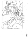
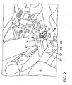
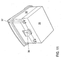
- Fig. 1 and 2 is a preferred embodiment of a device according to the invention for hot water or steam generation as hot water preparation module 1, as shown schematically and in perspective in the Fig. 3 is shown, in a preferred use in the region of a center console 2 of a vehicle interior between a driver's seat 3 and a front passenger seat 4 shown.
- the hot water preparation module 1, as shown in the Fig. 3 is shown in the uninstalled state, a screen 5, which forms part of the center console 2 in the mounted state of the hot water preparation module 1, as is known from Fig. 1 and 2 is apparent.
- this screen 5 opens a trained in the manner of a water outlet tapping point 6, which is designed in the manner of a valve element, which will be explained in more detail below in connection with specific embodiments, wherein the tapping parts in a subsequent to the screen 5 downwards Module receiving housing 7, which in the Fig. 5 is shown in a schematic and perspective plan view are added.
- This module-receiving housing 7 is stored stowed in the installed state in the area of the center console 2, so that in the vehicle interior only the screen 5 with tapping point 6 visible and for the connection of a z.
- B. coffee mug 8 is accessible for a coffee preparation, as shown schematically in the Fig. 2 and in the Fig. 3 is shown, which in each case shows a coffee cup 8 connected to the tapping point 6 in order to tap off a quantity of hot water for a coffee preparation via the tapping point 6, which will be explained in more detail below with a concrete exemplary embodiment.
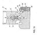
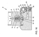
- FIG. 15 shows here only a lower than connecting counter-element 9 formed region of a z. B. designed as a coffee cup 8 tap connection element, the can be releasably locked by means of a bayonet closure connection 10 with the tapping point 6, as shown in the Fig. 16 is shown.
- an inflow channel 11 is formed, which in the in Fig. 15 shown basic position is sealed by means of a biased in the closing direction by a spring 12 shut-off means 13 as a displaceable obturator, including in the bottom-side mouth region of the inflow 11 also sealing elements 14 are arranged.
- a connection counter-element side locking hook 17 of a bayonet connection 10 to release the water or steam supply into the valve element flow channel 16 and thus into the inflow 11 into when inserting the connection counter-element 9 in the tapping point 6, a zapfstellen suit pivotally mounted about a pivot axis 18 safety lever 19 which cooperates with a lever end with a safety pin 20, so shift that this safety pin 20 by the displacement of the safety lever 19 from in the Fig. 15 shown closure position 21 in the in the Fig. 16 shown release position 20 is shifted.
- this in the Fig. 16 shown release position is aligned with a security bolt side provided flow opening 23 with the valve element flow channel 16 and is a z. B. hot water flow in the valve element flow channel 16 free, as indicated by the arrow 24 only schematically.
- the safety pin 20 is biased together with safety lever 19 in the basic position by a spring 25 in the closed position 21.
- control knob 26 in conjunction with in the Fig. 15 and 16 embodiment shown but also be provided to, as will be explained in more detail below, to operate a heater having a pump and a thermoblock to set the hot water and thus the hot water production only in motion, ie, that in conjunction with an embodiment as they are in the Fig. 15 and 16 was explained, first only the flow path in the z. B. coffee cup 8 is released into it before the actual hot water or steam preparation, production and - feed done by pressing the control knob 26.
- control knob 27 may, for. B. in conjunction with the control knob 26 on the one hand a power switch (control knob 26) and on the other hand, a switch (control knob 27) provide, with the hot water preparation module 1 is turned off when enough hot water or hot steam has been tapped.
- the variants just described are only a part of various possibilities in order to realize a corresponding control of hot water preparation or superheated steam preparation and have been explained here only by way of example in order to explain one type of concrete embodiment of the hot water preparation module 1 according to the invention.
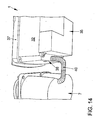
- the tapping point 6 is also associated with a water tank forming a water tank 28, which also accommodated in the module receiving housing 7 and there with a in the Fig. 5 only extremely schematically illustrated water tank connection piece 29 is fluidly connected by means of which water can be withdrawn from the water tank 28 to the heater, as will be explained in more detail below.
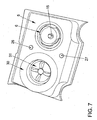
- This water tank opens, as in particular the FIGS. 6 and 7 can be taken, the different assembly states of this module-receiving housing 7, also in the screen 5, wherein the container opening of the water tank 28 with a container lid 30 is releasably closed, which is provided in a dual function at the same time on its top cover with a Cupholder function 31.
- This can, as in particular the Fig. 1 and the Fig. 2 can be removed, installed in the vehicle state a simple filling of the water tank 28 are provided, since this only the freely accessible container lid 30 must be unscrewed.
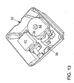
- Fig. 6 the assembly state of the module-receiving housing 7 is shown without cover through the screen 5, which here again very well the exemplary arrangement of the two control buttons 26 and 27 can be seen, the electronics is also included in the module receiving housing 7.
- Fig. 7 then represents the assembly state in which the screen 5 is installed.
- This screen 5 is preferably with such z. B. wood decor or the like provided or formed from such that fits harmoniously into the interior design of the vehicle, for. B. is formed identical to the decorative inserts.
- Fig. 8 the assembly of the module receiving housing 7 is shown again in a perspective exploded view.
- the components have previously been detailed in terms of their function, so that will not be discussed in more detail.
- the hot water preparation module 1 further comprises a mounting box 32 as a receiving housing for a heater 33.
- This mounting box can be designed differently depending on the vehicle type, as this only very schematically and by way of example in the Fig. 9 is shown. So z. B. the mounting box 32 for an embodiment in which more storage space in the vehicle longitudinal direction in the area of a center console 2 is provided with an additional box 34, which is laterally attached to the mounting box 32 in particular via a screw connection. This can be z. As in sedans, especially luxury-class sedans be the case. For vehicle types, such. B.
- SUV's on the other hand, if necessary, more space in vehicle vertical axis direction as storage space for the mounting box 32 is present, so that an additional box 35 can be attached here to a bottom of the mounting box 32, z. B. via a screw connection.
- the electrical system is preferably stowed, as is required for a recorded in the mounting box 32 heater 33.
- different mounting box cover 36, 37 may be provided, which may also be formed depending on the vehicle type different from the length, width and height.
- the further embodiment of the mounting box 32 is explained exclusively in conjunction with an arranged below the mounting box 32 additional box 35, however, an analogous structure with a laterally arranged additional box 34 is also possible at any time.
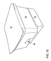
- the mounting box 32 with arranged below additional box 35 and mounting box lid 37 in the assembled state is in the Fig. 10 shown in a schematic, perspective front view.
- the assembly of the Fig. 10 shown in a perspective bottom view, here well a pit opening 38 is visible can be passed through the system lines out of the mounting box 32 out to the module-receiving housing 7, where this, as in particular the Fig. 5 can be removed via a corresponding housing opening. 39 in the interior of the module receiving housing 7 to the arranged there corresponding components of the water tank 28 and the water tank connection piece 29 and to the tapping point 6 can be out.
- Fig. 10 shown in a schematic, perspective front view.
- the assembly of the Fig. 10 shown in a perspective bottom view, here well a pit opening 38 is visible can be passed through the system lines out of the mounting box 32 out to the module-receiving housing 7, where this, as in particular the Fig. 5 can be removed via a corresponding housing opening. 39 in the interior of the module receiving housing 7 to the arranged there
- the heater 33 comprises on the one hand an electric pump 41 and on the other hand an electrically heatable thermoblock 42 as a heating block, by means of which the heated via connecting lines or connecting channels from the water reservoir by means of the electric pump 41 heated water to a predetermined temperature and turn over corresponding connection lines or connection channels with a predetermined pressure at the tapping point 6 can be provided.
- the thermoblock is preferably operated with a low voltage of 12 volts and a heating power of about 180 watts.
- the electronic components of the heating device 33, in particular cables and / or boards 43, 44 are received in the additional box 35, wherein the required electrical lines are optionally passed through a pit wall into the mounting box 32.
- the control of the heater 33 is z. B. made by actuation of a control device by means of z. B. the control buttons 26, 27 can be controlled.
- the electric pump is preferably stored on pump bearings 45, 46 in the interior of the mounting box 32 to ensure a stable and firm connection of the pump.
- a preferably pivotable center armrest 47 which covers the mounting box 32 in direct connection to the screen 5.
- hot water preparation module 1 for preparing coffee or for providing a hot-moist refreshing towel are explained in more detail below:
- the Fig. 17 and 18 show schematically and as a sectional view of a coffee cup 8 formed as a connecting counter-element, which in the Fig. 17 in an exploded view and in the Fig. 18 in the assembled, assembled and also coupled to the tap 6 state is shown.
- the coffee cup 8 has a drinking vessel 48, which is connected by means of a detachable screw connection by means of an extraction head 49 as a brewing unit or brewing, for which on the drinking vessel 48 in the region of a bottom wall of the same edge a projection with an internal thread 50 is formed, the extraction head side with a projection an external thread 51 is assigned, so that the extraction head 49 can be screwed into the bottom wall portion of the drinking vessel 48.
- the internal thread 50 and the external thread 51 together with their projections, on which this thread is formed, are arranged and formed in an annular manner on the edge side, so that an inflow opening formed by an inflow channel 52 can be provided on the bottom wall of the drinking vessel 48 in a central, central region which extends from the bottom wall of the drinking vessel 48, starting from a tower or tube upwards into the interior of the vessel, in the example shown here extending approximately to half the height of the height of the interior of the vessel.
- the height extent of the inflow channel 52 is here preferably dimensioned such that it corresponds approximately to a predetermined fill level of a coffee extract in the drinking vessel 48.
- the inflow channel 52 is here exemplified material and formed integrally with the bottom wall, z. B. of a plastic material.
- the inflow channel can also be formed by a separate component which is connected to the bottom wall by a mechanical connection, for. B. by a screw-in.
- a cutting grid 53 is arranged, whose function will be explained later in more detail.
- the inlet channel 52 is formed in the vessel interior by means of a designed in the manner of a check valve obturator 54 which releases a coffee extract volume flow into the drinking vessel 48 only when reaching a predetermined opening pressure and prevents leakage or low opening pressure, the outflow of the coffee extract from the vessel interior.
- this obturator 54 is disposed at the free end of the inflow 52 and simultaneously forms a deflecting element with a tubular, here slightly convex curved or cambered T-crosspiece 55, which deflects the flow of coffee extract in the direction of side and bottom wall of the drinking vessel 48 ,
- the obturator 54 is made of an elastomeric material, for. B. as a kind of inflatable tube, which inflates and expands at a predetermined pressure so that inflow are released, while the inflow remain without this pressure but closed or not formed.
- annular gap 58 is formed on the extraction head side by a receiving edge region 56 having the external thread 51 and a further, so-called portion-receiving wall region 57 which adjoins it inwardly.
- a receiving space is provided, in which z. B. when loosening the drinking vessel 48 from the extraction head 49 dripping coffee extract can be safely collected in the extraction head, so that dripping on the floor or in the vehicle, if this dissolution of drinking vessel 48 and extraction head 49 should be carried out in the vehicle interior, functionally reliable prevented can be.
- the drinking-vessel-side bottom wall region together with cutting grid 53 and inflow channel 52 is assigned to an end face of the extraction head 49 in which a coffee port receptacle 60 is provided, in particular through the annular portion-receiving edge region 57, into which a coffee portion capsule 61 can be inserted in a form-fitting manner.
- a capsule underside is formed by a spinous process 62 protruding into the coffee portion receptacle 60, which will be described in more detail below, perforated.
- the cutting grid 53 is pressed into the capsule top, whereby it is perforated.
- the coffee serving capsule 61 perforating spinous process 62 of the coffee port receptacle 60 is channel-shaped or tubular and communicates with a extraction head side water channel 63 as an inflow in flow communication.
- the spinous process 62 can be a separate. Be component that is screwed by means of a threaded connection in the extraction head.
- the extraction head 49 as a counter-receptacle element in two parts from a first, the drinking vessel 48 associated head portion 64 in which the coffee portion receptacle 60 is formed, and from a second, the tapping point 6 associated head part 65 is formed.
- the second head part 65 has an external thread, which is assigned an internal thread on the first head part 64, so that the second head part 65 with its external thread can be screwed into the internal thread of the first head part 64, with the interposition of a ring seal surrounding the water channel region 66 can here, as well as between the drinking vessel 48 and the extraction head 49, the threaded arrangement between the components also be reversed, ie z. B. be formed as an external thread on the first head part.
- a spring-loaded obturator 13 is substantially centrally and centrally formed, which as well as the tapping point 6 analogous to that previously in connection with the FIGS. 15 and 16 ge Teslaten embodiments of the local connection counter-element 9 and the local tapping point 6 is formed so that reference is made here with respect to the further operation of the local statements, especially in conjunction with the Fig. 17 and the Fig. 18 also the local reference numerals are used.
- the extraction head 49 forming the receiving counter-element thus has a two-part design, but this has only manufacturing and assembly-related reasons, but no further effect on the functionality as a connecting counter-element or extraction head 49.
- the drinking vessel 48 has a circumferential grip ring 67, which at least partially made of a heat-insulating Material is made.
- This handle ring 67 can by a separate, with the drinking vessel, eg. B. be formed via an adhesive and / or groove connection connectable component.
- the arrangement of a conventional handle or handle is possible.
- locking locking device 68 is provided on the first head portion 64, which is formed by a displaceable on the first head lock rod 69, which is not connected to the tapping point 6 state of the extraction head 49 by means of a spring element 70 in the in the Fig. 17 shown unlocking position is urged, in which a connected to the locking rod 69 stop 71 projects beyond a bottom wall portion 72 of the first head portion 64.
- This stop 71 or this bottom wall region 72 is assigned a counterstop 73 on the tap end, which is at the same time an integral part of the bayonet closure 10 here.
- Both the locking by means of the locking device 68 and the vent is, as previously shown, only optional and need not necessarily be provided.
- the tap connection element is designed as a so-called hot towel receptacle:
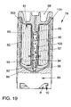
- the hot towel receptacle 79 is in the Fig. 19 shown schematically and by way of example in a sectional view in the assembled state with inserted towel 80.
- the exact structure of this Hot Towel receptacle is exemplified above all with reference to Fig. 20 and 21 explained in more detail.
- the hot towel receptacle 79 comprises a cup-like insert part 82 forming a hot towel receptacle 81, which, as shown particularly in FIGS Fig. 20 can be seen, can be positively inserted into the main body 83 of the hot-towel receptacle 79.
- This insert part 82 has at the lower end part of the insert 83 forming a connection counter-element bottom region 84 diverse and spaced apart and over a predetermined length over a predetermined length along the insert outer wall extending bores or channel-shaped or groove-shaped recesses in the positively inserted state of the insert member 82 then between just the insert member 82 and the base 83 a plurality of spaced apart and along a predetermined peripheral region or over a predetermined geodetic height extending nozzle channels 85, 86 is formed, of which, for technical reasons, only two are shown.
- nozzle channels 85, 86 open with nozzles 87, 88 turn into the hot-toweling receiving space 81.
- the nozzle channels 85, 86 further open with their nozzles 87, 88 opposite channel ends in an inflow 89, which is formed in the receiving counter element forming bottom portion 84 of the hot towel receptacle 79 and the body 83, and about which, as will be explained in more detail below, water flows from a tapping point into the hot-towel receptacle 79.
- the insert 82 has an integrally formed receiving space mandrel 90, which extends from the bottom portion of the insert portion 82, starting up into the hot-towel receiving space 81 inside.
- a mandrel insert 92 are inserted positively such that by corresponding provision of holes or channel or groove-shaped recesses on the Dornun outside, between the mandrel insert 92 and the receiving space mandrel 90 more along a predetermined circumferential area and Over a predetermined geodetic height extending nozzle channels 93, 94 are formed.
- nozzle channels 93, 94 which have different geodetic heights here, open on the one hand via the nozzles 95, 96 into the hot-towel receiving chamber 81 and on the other hand in the region of an inlet opening 97 of the insert part in fluid communication with the inlet channel 89.
- more than two nozzle channels 93, 94 may be formed.
- a lid 98 is also placed on the hot towel receptacle 79, on the lid underside of which a lid extension 99 is formed, which is integral with the lid 98 may be formed, but also as a separate component with the lid 98 may be firmly connected.
- the lid 98 on its underside a socket 100 which in turn may also be integrally formed with the lid 98 or may also be formed by a separate component which can be connected to the lid 98.
- This plug-in sleeve 100 is inserted in the mounted state on the receiving space mandrel 90 and takes this form-fitting in such a way that the receiving space-thorn-side nozzles 95, 96 are aligned with plug-sleeve-side nozzles 101 and 102.
- this is shown here by way of example only in connection with two nozzles.
- another can be another Number of nozzles to be specified.
- the nozzles may be at least partially also at geodetically different heights.
- the receiving space mandrel side nozzles 95, 96 are aligned with the plug-sleeve-side nozzles 101, 102, z. B. between the lid 98 insert 82 may be provided here by way of example by two locking lugs 103, 104 positioning aid.
- the hot-towel receiving space 81 preferably has an elongated, cylindrical inner geometry, so that the towel 80 is received in the hot-towel receiving space 81 substantially positively in the rolled state.
- the flow connection between a tap-side flow channel 16 and the inflow channel 89 is made, so that z. B. hot water or superheated steam via the inlet channel 89 and the nozzle channels 85, 86, 93, 94 in the hot-toweling receiving space 81 and there may apply the towel 80 according to hot water or hot steam.
- the safety pin 20 is actuated here again by means of the locking hook 17 of the bayonet lock 10, as previously described in connection with the Fig. 15 and 16 has been explained in detail and in detail.
- the hot-towel receptacle 79 is explicitly referred to the statements made above, which is particularly true of the embodiments in connection with the Fig. 17 and 18 applies.
- the lid 98 can then be removed and the towel 80 used for refreshment or served.
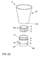
- FIG. 23 and 24 schematically again the coffee cup 8 is shown, which is provided with a decorating sleeve 105 as a decorative element.
- the drinking vessel 48 and the extraction head 49 are shown here only schematically and specifically designed according to the embodiment shown above.
- the extraction head 49 on a Aufsteck Scheme 107 which extends from the annular collar 106, starting at the height a upwards to the area where the external thread 51 begins.
- the slip-on sleeve 105 likewise has a height extent of approximately a, the slip-on sleeve 105, in the plugged-on state, essentially enclosing the attachment region 107 of the extraction head 49 in a form-fitting manner, if appropriate also in conjunction with a clamping connection.
- the drinking vessel 48 After attaching the slip-on sleeve 105, the drinking vessel 48 is screwed with its internal thread not apparent here on the external thread 51 of the extraction head 49, so that the coffee cup 8 is fully assembled.
- the drinking vessel 48 itself also on the bottom side has a circumferential annular collar 108, by means of which the drinking vessel in the in Fig. 24 shown assembled state flush with the decorative element forming a plug-in sleeve 105 can connect.
- the slip-on 105 a slightly, z. B. by 1 mm or the like greater height extent than that specified by the dimension a, so that the slip-on 105 in the in the Fig. 24 shown screwed state of the drinking vessel 48 on the extraction head between the two annular collars 106, 108 is clamped.
- the slip-on sleeve 105 can be designed differently on a visible side, z. B. be designed according to the decorative inlays of an interior design of a vehicle, such. B. according to a wooden version or an aluminum version, just to name a few. Particularly preferred is a harmonizing with the screen 5 design, z. B. an identical design with respect to the design.
- the drinking vessel 48 itself may be additionally or alternatively provided on its outside with a corresponding decorative element, for. B. have on its outside a visible side, the z. B. to a recurring design element of an interior design, z. B. a decorative insert is adjusted.
Landscapes
- Engineering & Computer Science (AREA)
- Food Science & Technology (AREA)
- Transportation (AREA)
- Mechanical Engineering (AREA)
- Vehicle Step Arrangements And Article Storage (AREA)
- Apparatus For Making Beverages (AREA)
- Air-Conditioning For Vehicles (AREA)
Abstract
Description
Die Erfindung betrifft eine Anordnung einer Vorrichtung zur Heißwasser- oder Dampferzeugung nach dem Oberbegriff des Anspruchs 1.The invention relates to an arrangement of a device for hot water or steam generation according to the preamble of
Der Einsatz von Vorrichtungen zur Heißwassererzeugung ist in Fahrzeugen in Verbindung mit der Herstellung von Aufgussgetränken, wie beispielsweise Kaffee, bereits bekannt. So ist es beispielsweise aus der
Aus der
Ein ähnliches Prinzip mit einem Wasserhahn, bei dem die Flüssigkeit von oben her in einen darunter abgestellten oder gehalterten Behälter eintropft, zeigen auch die
Weiter ist aus der
Weiter ist aus der
Vorrichtungen zur Heißwassererzeugung bzw. Kaffeemaschinen sind ferner auch aus der
Demgegenüber ist es Aufgabe der vorliegenden Erfindung, eine alternative Anordnung einer Vorrichtung zur Heißwasser- oder Dampferzeugung zur Verfügung zu stellen, mittels der Heißwasser oder Dampf auf technisch einfache sowie auf optisch ansprechende Weise für eine Vielzahl von Anwendungsfällen zur Verfügung gestellt werden kann.In contrast, it is an object of the present invention to provide an alternative arrangement of a device for hot water or steam generation available by means of hot water or steam in a technically simple and visually appealing way for a variety of applications can be provided.
Diese Aufgabe wird gelöst mit den Merkmalen des Anspruchs 1. Vorteilhafte Weiterbildungen hierzu sind Gegenstand der Unteransprüche.This object is achieved with the features of
Gemäß Anspruch 1 ist eine Anordnung einer Vorrichtung zur Heißwasser- oder Dampferzeugung in einem einen Wandbereich aufweisenden Fahrzeug oder Gebäudeinnenraum vorgesehen, bei der die Vorrichtung wenigstens einen Wasserspeicher sowie wenigstens eine Heizeinrichtung aufweist, mittels der Wasser auf eine vorgegebene Temperatur erwärmt werden kann. Die Vorrichtung weist ferner wenigstens eine Zapfstelle für ein insbesondere chargenweises Abzapfen von Wasser und/oder Dampf auf, die, insbesondere gegebenenfalls auch zur Zapfstellenbetätigung und/oder zur Freigabe einer vorgegebenen Wasser- oder Dampfmenge, mit einem Zapfstellen-Anschlusselement koppelbar oder verbindbar ist. Erfindungsgemäß ist weiter vorgesehen, dass die wenigstens eine Zapfstelle in der Art einer Anschlusskupplung oder in der Art einer Dampf- oder Wassersteckdose in einem Wandbereich des Fahrzeuges oder Gebäudeinnenraums mündet und durch eine Art Ventilelement gebildet ist oder ein solches umfasst, wobei das Ventilelement bei einer Ventilbetätigung Wasser oder Dampf in der gewünschten Menge, insbesondere auch chargenweise freigibt. Unter einem Ventilelement wird hierbei in allgemeinster Weise eine mechanisch, elektronisch oder von Hand betätigbare bzw. gesteuerte und absperrbare Einlass-, Auslass- oder Durchtrittsvorrichtung für Dampf oder Wasser verstanden. Ein derartiges mechanisch und/oder elektronisch betätigbares Ventilelement ist einfach und preiswert in der Herstellung und zudem funktionssicher in der Bedienung. Das bevorzugt im Wesentlichen die Zapfstelle ausbildende Ventilelement weist zudem vorteilhaft einen in einer Ventilruhestellung mittels eines Absperrelementes absperrbaren und bei einer Ventilbetätigung mittels des Absperrelementes freigebbaren Ventilelement-Strömungskanal auf, der bevorzugt selbst oder mit einem weiterführenden Anschlusskanal zur Heizeinrichtung geführt und mit dieser mittelbar oder unmittelbar strömungsverbunden ist. Zum Beispiel mündet die wenigstens eine Zapfstelle an einem fahrzeugseitigen Wandbereich, bevorzugt an einem fahrzeugseitigen Innenraumwandbereich. Hierdurch ist neben einer einfachen Zugänglichkeit auch eine wenig störende und optisch ansprechende Möglichkeit für die konkrete Ausgestaltung einer derartigen erfindungsgemäßen Zapfstelle geschaffen. Eine besonders bevorzugte Weiterbildung hierzu sieht vor, dass die Zapfstelle in der Art einer Dampf- oder Wassersteckdose insbesondere im Wesentlichen oberflächenbündig in einem fahrzeugseitigen Wandbereich, bevorzugt in einem fahrzeugseitigen Innenraumwandbereich mündet.According to
Eine derartige Zapfstelle kann an verschiedensten Stellen eines z. B. Fahrzeugs, insbesondere eines Fahrzeuginnenraums angeordnet werden, z. B. in Stauräumen, wie dem Kofferraum. Bevorzugt ist jedoch eine Anordnung einer derartigen Zapfstelle in einem Fahrgastraum als Innenraumbereich eines Fahrzeuges, insbesondere eines Kraftfahrzeuges. Ein besonderer Vorteil einer derartigen Zapfstelle ist die Möglichkeit, jederzeit für unterschiedlichste Anwendungsfälle eine geeignete Menge an Heißwasser oder Dampf zur Verfügung zu stellen. Das heißt, dass eine separate Wasser-Zapfstelle im Fahrzeug zur Verfügung gestellt wird, die unabhängig von einer z. B. Kaffee- oder Espressomaschine bedient werden kann und somit auch für andere Einsatz- bzw. Anwendungsfälle zur Verfügung steht, was die Funktionalität der Vorrichtung wesentlich erhöht. Unabhängig von der bevorzugten Verwendung in Fahrzeugen kann die erfindungsgemäße Vorrichtung aber auch universeller eingesetzt bzw. verwendet werden, so z. B. als Wasserzapfstelle, vorzugsweise als Heißwasser- oder Dampfzapfstelle in Büros, Küchen oder dergleichen. Ein besonderer Vorteil einer derartigen Verwendung besteht z. B. in Verbindung mit einem z. B. als Kaffeebecher ausgebildeten Zapfstellen-Anschlusselement, was nachfolgend noch näher erläutert wird. Nachfolgend wird die Erfindung im Wesentlichen in Verbindung mit einer besonders bevorzugten Verwendung in Fahrzeugen beschrieben und erläutert, was jedoch nur beispielhaft zu verstehen ist. Sofern eine bestimmte Verwendung auch unabhängig vom Fahrzeug, z. B. im Büro- oder Officebereich, möglich ist, soll dies ausdrücklich vom Schutzumfang mitumfasst sein.Such a tap can at various points of a z. B. vehicle, in particular a vehicle interior are arranged, for. B. in storage space, such as the trunk. However, an arrangement of such a tap in a passenger compartment is preferred as the interior region of a vehicle, in particular of a motor vehicle. A particular advantage of such a tap is the ability to provide an appropriate amount of hot water or steam at any time for a variety of applications. This means that a separate water tapping point is provided in the vehicle, the regardless of a z. B. coffee or espresso machine can be operated and thus also for other applications or applications is available, which significantly increases the functionality of the device. Regardless of the preferred use in vehicles, the device according to the invention can also be used or used more universally, such. B. as a water tapping point, preferably as a hot water or steam tap in offices, kitchens or the like. A particular advantage of such use is z. B. in conjunction with a z. B. designed as a coffee cup Zapfstellen connecting element, which will be explained in more detail below. In the following, the invention will be described and explained essentially in connection with a particularly preferred use in vehicles, which is to be understood only as an example. If a particular use and independent of the vehicle, z. For example, in the office or office area, this should be explicitly included in the scope of protection.
Es versteht sich; dass mittels einer derartigen erfindungsgemäßen Vorrichtung selbstverständlich nicht nur Heißwasser oder heißer Wasserdampf (Dampf) erzeugt werden kann, sondern dass darüber hinaus, z. B. durch entsprechende Abschaltung der Heizeinrichtung bzw. eines Heizmoduls auch nicht erwärmtes Wasser zur Verfügung gestellt werden kann. An dieser Stelle sei ausdrücklich erwähnt, dass für den Fall, dass keine Heißwasser- oder Dampferzeugung gewünscht sein sollte, die Heizeinrichtung der erfindungsgemäßen Vorrichtung entbehrlich ist, so dass neben einem Wasserspeicher und gegebenenfalls einer Förderpumpe lediglich die wenigstens eine erfindungsgemäße Zapfstelle fahrzeugseitig vorzusehen ist. Dies soll ausdrücklich mit vom Schutzumfang umfasst sein, wenngleich die Kombination mit einer Heizeinrichtung, um gleichzeitig auch eine Dampf- oder Heißwasserbereitstellung mit anzubieten bevorzugt ist. Unter heißem Wasser wird dabei im Falle der vorliegenden Erfindung jegliches auf eine höhere Temperatur als Umgebungstemperatur erwärmtes Wasser verstanden. Anstelle von Wasser können zudem selbstverständlich auch andere Flüssigkeiten eingesetzt werden. Der Begriff Wasser ist somit hier als Synonym für sämtliche zum Einsatz in Verbindung mit der erfindungsgemäßen Vorrichtung geeigneten Flüssigkeiten oder fluide Medien zu verstehen.It goes without saying; that by means of such a device according to the invention, of course, not only hot water or hot steam (steam) can be generated, but that beyond, for. B. by appropriate shutdown of the heater or a heating module and not heated water can be provided. It should be expressly mentioned that in the event that no hot water or steam generation should be desired, the heating device of the device according to the invention is dispensable, so that in addition to a water reservoir and optionally a feed pump, only the at least one tap according to the invention is provided on the vehicle side. This is to be expressly included in the scope of protection, although the combination with a heater in order to simultaneously offer a steam or hot water supply with is preferred. By hot water is meant in the case of the present invention, any heated to a higher temperature than ambient temperature water. Of course, other liquids can be used instead of water. The term water is therefore to be understood here as a synonym for all liquids or fluid media suitable for use in connection with the device according to the invention.
Weiter kann die Zapfstelle gemäß einer bevorzugten Ausgestaltung in einer Bestandteil des Wandbereichs bildenden oder mit dem Wandbereich verbindbaren Blende oder Konsole münden. Eine derartige Blende oder Konsole kann, insbesondere in Verbindung mit einer Modulbauweise neben einer geeigneten Halterungs- und/oder Anordnungsmöglichkeit einer Zapfstelle im Fahrzeug optisch auch so gestaltet werden, dass diese sich z. B. in ein wiederkehrendes Designelement eines Fahrzeuges harmonisch einfügt und gleichzeitig den speziellen Anforderungen für die Lagerung einer Zapfstelle genügt. Gleiches gilt für z. B. andere Anwendungen, wie z. B. im Küchen- oder Bürobereich, z. B. in Verbindung mit Arbeitsplatten oder dergleichen.Furthermore, according to a preferred embodiment, the tapping point can open into a diaphragm or console which forms part of the wall region or can be connected to the wall region. Such a panel or console, in particular in conjunction with a modular design in addition to a suitable mounting and / or arrangement possibility of a tap in the vehicle visually also be designed so that these z. B. fits harmoniously into a recurring design element of a vehicle and at the same time meets the special requirements for the storage of a tap. The same applies to z. B. other applications, such. B. in the kitchen or office area, z. B. in connection with worktops or the like.
Wie bereits zuvor geschildert, kann die erfindungsgemäße Zapfstelle an unterschiedlichen Positionen eines bevorzugt Fahrzeugs angeordnet sein. Besonders bevorzugt ist jedoch der Wandbereich Bestandteil einer Innenausstattung und/oder Innenverkleidung eines Fahrgastraumes eines Fahrzeugs. Der Begriff Innenausstattung und Innenverkleidung ist hierbei im umfassenden Sinne zu verstehen und umfasst z. B. auch Bauteile wie die Mittelkonsole, Seitenverkleidungen oder dergleichen.As already described above, the tap according to the invention can be arranged at different positions of a preferred vehicle. However, the wall area is particularly preferably part of an interior trim and / or interior trim of a passenger compartment of a vehicle. The term interior and interior trim is to be understood in a comprehensive sense and includes z. As well as components such as the center console, side panels or the like.
Gemäß einer besonders bevorzugten konkreten Ausgestaltung ist zudem vorgesehen, dass die wenigstens eine Zapfstelle im Bereich zwischen zwei benachbarten Sitzpositionen des Fahrgastraumes angeordnet ist. Dadurch ist eine besonders einfache Zugänglichkeit der Zapfstelle gewährleistet. Besonders vorteilhaft ist es, wenn die wenigstens eine Zapfstelle Bestandteil einer zwischen Fond- und/oder Frontinsassenposition angeordneten oder anordenbaren und einen Innenraumwandbereich bildenden Mittelkonsole ist. In einer derartigen Mittelkonsole können die Bauteile der erfindungsgemäßen Vorrichtung auf besonders einfache Weise zuverlässig und gut zugänglich verstaut angeordnet werden, ohne dass diese im Innenraum als störend empfunden werden bzw. in unüblicher Weise im Fahrgastraum angeordnet werden müssen. Dies ist insbesondere dann der Fall, wenn die wenigstens eine Zapfstelle in einem Bereich oder anstelle der dort üblicherweise angeordneten Cupholder vorgesehen wird.According to a particularly preferred specific embodiment, it is additionally provided that the at least one tap point is arranged in the region between two adjacent seat positions of the passenger compartment. This ensures a particularly easy accessibility of the tap. It is particularly advantageous if the at least one bleed point is part of a center console which is arranged or can be arranged between the rear and / or front occupant position and forms an interior wall area. In such a center console, the components of the device according to the invention can be arranged stowed reliably and easily accessible in a particularly simple manner, without these being perceived as disturbing in the interior or must be arranged in an unusual manner in the passenger compartment. This is the case in particular if the at least one tap is provided in an area or instead of the cup holders usually arranged there.
Für den Fall, dass das Fahrzeug mehrere Zapfstellen aufweist, kann vorgesehen sein, dass diese Zapfstellen jeweils unabhängig voneinander bedienbare Einheiten darstellen. Für den Fall jedoch, dass wenigstens ein Teil dieser mehreren Zapfstellen von demselben Wasserspeicher bzw. von derselben Heizeinrichtung gespeist wird, ist bevorzugt eine Steuereinrichtung vorgesehen, mittels der im Falle der Betätigung einer der Zapfstellen die anderen oder wenigstens ein Teil der anderen Zapfstellen gesperrt oder deaktiviert sind. Dadurch lässt sich eine Fehlbedienung zuverlässig ausschließen. Beispielsweise kann vorgesehen sein, dass wenigstens eine Zapfstelle im Fondbereich und wenigstens eine Zapfstelle im Frontbereich eines Fahrgastraumes vorgesehen sind, die über einen gemeinsamen Wasserspeicher und eine gemeinsame Heizeinrichtung gespeist werden.In the event that the vehicle has a plurality of taps, it can be provided that these taps represent each independently operable units. In the event, however, that at least a portion of these multiple taps is fed by the same water storage or the same heater, a control device is preferably provided by means of which the other or at least a part of the other taps blocked or deactivated in the case of actuation of one of the taps are. As a result, a misuse can be reliably excluded. For example, it can be provided that at least one tap in the rear area and at least one tap in the front of a passenger compartment are provided, which are fed via a common water storage and a common heating device.
Gemäß einer weiteren besonders bevorzugten konkreten Ausgestaltung bildet das Ventilelement bzw. die Zapfstelle in einer vorteilhaften Doppelfunktion gleichzeitig eine Art Anschlusskupplung oder Steckdose aus, mittels der eine mit einem Anschlussgegenelement ausgebildete Anschlusseinrichtung als Zapfstellen-Anschlusselement lösbar mit dem Ventilelement bzw. der Zapfstelle verbunden werden kann. Die Zapfstelle soll hierbei, z. B. fahrzeugseitig, so zugänglich sein, dass diese entweder von vorneherein frei zugänglich in einem Fahrzeug-Innenraum bzw. einem entsprechenden Wandbereich angeordnet ist oder dass diese nach dem Entfernen einer Schutzabdeckung oder dergleichen frei zugänglich ist. Mit der gleichzeitigen Integration einer derartigen Anschlusskupplungsfunktion in das Ventilelement bzw. die Zapfstelle wird die Bauteilvielfalt reduziert und gleichzeitig eine funktionssichere und einfach zu bedienende Anschlussmöglichkeit bzw. Abzapfmöglichkeit von Wasser zur Verfügung gestellt. Dies begünstigt den Wunsch, Wasser im Fahrzeug möglichst tropffrei abzapfen zu können, um keine unerwünschte Verunreinigung im Fahrzeug zu erhalten.According to a further particularly preferred specific embodiment, the valve element or the tap in an advantageous dual function at the same time a kind of connection coupling or socket, by means of which a connecting device formed with a connection counter element can be connected as a tap connection element releasably connected to the valve element or the tap. The tap should here, z. B. vehicle side, be accessible so that this is either arranged from the outset freely accessible in a vehicle interior or a corresponding wall area or that this is freely accessible after removing a protective cover or the like. With the simultaneous integration of such a connection coupling function in the valve element or the tapping point, the variety of components is reduced while providing a functionally reliable and easy-to-use connection option or tapping possibility of water available. This favors the desire to tap off water in the vehicle as possible drip-free, in order to obtain any unwanted contamination in the vehicle.
Gemäß einer besonders bevorzugten konkreten Ausgestaltung ist vorgesehen, die lösbare Verbindung als Formschluss- und/oder Kraftschlussverbindung, insbesondere in der Form einer Hintergriff- oder Bajonettverschluss-Verbindung auszubilden. Eine derartige mechanische Verbindung zeichnet sich durch eine hohe Funktionssicherheit aus und gewährleistet insbesondere für den Fall, dass z. B. Heißwasser für eine Espressobereitung mit einem hohen Druck von bis zu 19 bar zur Verfügung gestellt wird, kein unerwünschtes Abheben des dann als Trinkbecher ausgebildeten Zapfstellen-Anschlusselementes erfolgen kann.According to a particularly preferred specific embodiment is provided to form the releasable connection as form-fitting and / or frictional connection, in particular in the form of a rear grip or bayonet connection. Such a mechanical connection is characterized by a high reliability and ensures in particular for the case that z. B. hot water for an espresso preparation with a high pressure of up to 19 bar is provided, no unwanted lifting of the then designed as a drinking cup tapping connection element can be done.
Zur Zapfstellen- bzw. Ventilbetätigung selbst gibt es grundsätzlich mehrere Möglichkeiten. So kann z. B. das Zapfstellen-Anschlusselement eine mechanische Steuerungseinrichtung aufweisen, die insbesondere durch ein mechanisches Betätigungselement am Zapfstellen-Anschlusselement, insbesondere am Anschlussgegenelement, gebildet ist. Mittels einer derartigen mechanischen Steuerungseinrichtung kann das Absperrelement des Ventilelementes bei einer Verbindung von Ventilelement und Zapfstellen-Anschlusselement zuverlässig und im Wesentlichen selbsttätig beim Ankoppeln an die Zapfstelle in die den Ventilelement-Strömungskanal freigebende Freigabeposition verlagert und dort gehalten werden. Sofern die Wasser- und/oder Dampfabgabe nicht bereits bei diesem Ankoppeln freigegeben werden soll, kann gemäß einer bevorzugten Ausführungsform vorgesehen sein, dass über zusätzliche Bedienelemente, wie z. B. Schalter, Taster, Betätigungsknöpfe oder dergleichen, vom Bediener der Wasser- oder Dampfstrom funktionssicher und kontrolliert endgültig freigegeben wird. Diese Freigabe soll bevorzugt nur dann möglich sein, wenn das Zapfstellen-Anschlusselement richtig angekoppelt ist. Die Bedienelemente können z. B. über ein Display oder einen Bildschirm, z. B. in Verbindung mit einer z. B. fahrzeugseitigen Menüführung, angewählt werden. Ebenso ist aber auch eine Anordnung einer vorgegebenen Anzahl von Bedienelementen im Bereich der Zapfstelle möglich, z. B. an einer die Zapfstelle ausbildenden Sichtblende, Konsole oder dergleichen. Die endgültige Freigabe des Dampf- und/oder Wasserstroms zur Zapfstelle hin erfolgt hier somit durch Betätigung einer zusätzlichen der eigentlichen Zapfstelle vorgelagerten Absperreinrichtung, die auf beliebige Art ausgebildet sein kann.There are basically several options for the tap or valve actuation itself. So z. B. the tap connection element have a mechanical control device which is formed in particular by a mechanical actuating element on the tap connection element, in particular on the connection counter element. By means of such a mechanical control device, the shut-off of the valve element can be relocated reliably and substantially automatically when coupling to the tap in the valve element flow channel releasing release position and held there at a compound of valve element and tap connection element. If the water and / or steam delivery is not already released in this coupling, can be provided according to a preferred embodiment, that on additional controls such. As switches, buttons, operation buttons or the like, the operator of the water or steam flow is functionally reliable and controlled finally released. This release should preferably only be possible if the tap connection element is correctly coupled. The controls can z. B. via a display or a screen, for. B. in conjunction with a z. B. vehicle-side menu, be selected. Likewise, however, an arrangement of a predetermined number of controls in the tapping point is possible, for. B. on a tapping point forming screen, console or the like. The final release of the steam and / or water flow to the tapping point is thus effected here by actuation of an additional shut-off device upstream of the actual tapping point, which can be designed in any desired manner.
Alternativ oder aber gegebenenfalls auch zusätzlich dazu kann das Ventilelement auch mit einer elektronischen Steuereinrichtung gekoppelt sein, mittels der das Absperrelement für eine vorgegebene Zeitdauer mittelbar, z. B. über eine mittels der Steuereinrichtung aktivierbare und mit dem Absperrelement zusammenwirkende Betätigungseinrichtung, oder unmittelbar in die Freigabeposition verlagerbar ist. Bevorzugt weist die Steuereinrichtung analog zu der vorher beschriebenen Ausgestaltung hierzu wenigstens ein, z. B. fahrzeugseitig, zugängliches Bedienelement, z. B. einen Druckknopf oder einen Schalter oder dergleichen, auf, mittels dem die Steuereinrichtung manuell betätigt werden kann.Alternatively, or possibly also in addition thereto, the valve element can also be coupled to an electronic control device, by means of which the shut-off element can be indirectly, for example, for a predetermined period of time. B. via an activatable by means of the control device and with the shut-off cooperating actuator, or directly in the release position is displaced. Preferably, the control device analogous to the previously described embodiment, at least one, z. B. vehicle side, accessible control, z. As a push button or a switch or the like, by means of which the control device can be manually operated.
Insgesamt gesehen gibt es somit in Verbindung mit sowohl der mechanischen als auch der elektronischen Steuereinrichtung mehrere Möglichkeiten, mit ggf. zusätzlichen Bedienelementen, die Abzuzapfen gewünschte Wasser- oder Dampfmenge freizugeben, festzulegen oder auszuwählen. In einer einfachen Ausführungsform kann z. B. lediglich ein Ein- oder Ausschalten erfolgen, so dass eine Wasser- oder Dampfabgabe nur solange erfolgt, wie die Vorrichtung z. B. über einen Schalter oder dergleichen eingeschaltet ist. Auch eine Zeitsteuerung kann vorgesehen sein, z. B. dergestalt, dass bei einer Betätigung des Bedienelementes die Dampf- und/oder Wasserzufuhr für eine vorgegebene Zeit freigegeben wird und nach Ablauf der vorgegebenen Zeit wieder gesperrt wird. Dieses Sperren kann in Verbindung mit einer elektronischen Steuereinrichtung, mittels der das Absperrorgan verlagert wird, so erfolgen, dass das Absperrorgan wieder in seine Schließstellung zurückverlagert wird. In Verbindung mit einer mechanischen Steuereinrichtung zur für die Dauer der Ankupplung an die Zapfstelle im Wesentlichen dauerhaften Verlagerung des Absperrorgans kann das Sperren z. B. dadurch erfolgen, dass an anderer Stelle die Wasser- und/oder Dampfzufuhr mittels eines zusätzlichen Absperrelementes wieder unterbrochen wird. Beispielsweise können in Verbindung mit einer Heißwasserbereitstellung für eine Kaffeebereitung auch unterschiedliche Taster vorgesehen sein, denen jeweils unterschiedliche Mengen an freizugebendem Wasser zugeordnet sind, z. B. für unterschiedliche Kaffee-Arten oder Dampf- bzw. Wassermengen. Als zusätzliche Sicherungsfunktion kann in Verbindung mit einer derartigen Ausführungsform auch vorgesehen sein, dass die Bedienelemente bzw. die elektronische Steuereinrichtung nur bei mit dem Ventilelement verbundenem Zapfstellen-Anschlusselement betätigt werden können.Overall, therefore, there are several options in connection with both the mechanical and the electronic control device, with optional additional controls to release, select or select the desired amount of water or steam tapping. In a simple embodiment, for. B. only be switched on or off, so that a water or steam delivery only as long as the device z. B. is switched on via a switch or the like. A time control can be provided, for. B. in such a way that upon actuation of the control element, the steam and / or water supply is released for a predetermined time and is locked again after the predetermined time. This lock can be done in conjunction with an electronic control device by means of which the obturator, so that the obturator is moved back into its closed position. In conjunction with a mechanical control device for the duration of the coupling to the tap substantially permanent displacement of the obturator, the lock z. B. take place in that elsewhere the water and / or steam supply is interrupted by means of an additional shut-off again. For example, in connection with a hot water supply for a coffee preparation also different buttons may be provided, which are each assigned different amounts of water to be released, z. B. for different types of coffee or steam or water quantities. As an additional safety function may also be provided in connection with such an embodiment that the controls or the electronic control device can only be operated when connected to the valve element tap point connection element.
Ein besonders bevorzugtes Zapfstellen-Anschlusselement, insbesondere ein Anschlussgegenelement eines Zapfstellen-Anschlusselementes, das Bestandteil eines z. B. als Aufnahmegefäß ausbildbaren Zapfstellen-Anschlusselementes sein kann oder aber auch als separates Bauteil ausgebildet und mit dem Zapfstellen-Anschlusselement verbunden sein kann, sieht ein anschlusselementseitiges Absperrmittel vor, das einen Einströmkanal des Zapfstellen-Anschlusselementes bzw. des Anschlussgegenelementes in einer Grundstellung verschließt und das bei einer Verbindung von Zapfstellen-Anschlusselement oder Anschlussgegenelement mit dem Ventilelement bzw. der Zapfstelle einen anschlusselementseitigen Einströmkanal so freigibt, dass der anschlusselementseitige Einströmkanal und ein zapfstellenseitiger Strömungskanal, insbesondere der Ventilelement-Strömungskanal strömungsverbunden sind. Eine derartige Strömungsverbindung und Ausgestaltung von Anschlussgegenelement und/oder Zapfstellen-Anschlusselement ist wenig störanfällig und weist damit bei gleichzeitig relativ einfacher Herstellungsweise eine hohe Funktionssicherheit auf.A particularly preferred tap connection element, in particular a connection counter element of a tap connection element, the component of a z. B. can be embodied as a receptacle tap connection element or can also be formed as a separate component and connected to the tap connection element, provides a connection element-side shut-off, which closes an inflow passage of the tap connection element or the counter-connection element in a basic position and the in a connection of tapping connection element or connection counter element with the valve element or the tapping point a connection element side inflow so free that the connection element side inflow and a zapfstellenseitiger flow channel, in particular the valve element flow channel are fluidly connected. Such a flow connection and configuration of connection counter element and / or Zapfstellen connection element is less susceptible to interference and thus has at the same time relatively simple production a high level of reliability.
Besonders bevorzugt ist das anschlusselementseitige Absperrmittel durch ein in Richtung Grundstellung vorgespanntes, insbesondere federvorgespanntes Absperrorgan ausgebildet, das bei der Verbindung von Zapfstellen-Anschlusselement und Zapfstelle bzw. Ventilelement mittels eines zapfstellen- bzw. ventilelementseitigen Anschlussstutzens in die Freigabestellung verlagert und dort gehalten werden kann. Der zapfstellen- bzw. ventilelementseitige Anschlussstutzen ist dabei bevorzugt in etwa mittig und zentral im anschlussseitigen Ende der bevorzugt als Ventilelement angeordnet, so dass der Ventilelement-Strömungskanal im Bereich des ventilelementseitigen Anschlussstutzens münden kann. Dadurch ergibt sich insbesondere ein zweckmäßiger und kompakter sowie herstellungstechnisch einfacher Aufbau der Anschlussverbindung.Particularly preferably, the connection element-side shut-off means is formed by a biased in the basic position, in particular spring-loaded obturator, which can be displaced in the release position and held there in the connection of tapping point connection element and tapping point or valve element by means of a zapfstellen- or valve element-side connecting piece. The zapfstellen- or valve-element-side connecting piece is preferably approximately centrally and centrally in the connection end of the preferably arranged as a valve element, so that the valve element flow channel can open in the region of the valve element side connecting piece. This results in particular a convenient and compact as well as manufacturing technology simple construction of the connection.
Gemäß einer weiteren besonders bevorzugten Ausgestaltung der vorliegenden Erfindung ist die wenigstens eine Zapfstelle Bestandteil eines Heißwasserbereitungsmoduls. Dieses Heißwasserbereitungsmodul weist besonders bevorzugt eine Sichtblende als an einem fahrzeugseitigen Randbereich anordenbares oder Bestandteil eines solchen Wandbereiches bildendes Wandelement auf, und zwar bevorzugt in Form einer Konsole oder als Konsolenbestandteil. In einer derartigen Sichtblende kann eine vorgegebene Anzahl von Zapfstellen münden, die für eine Bedienung ggf. nach Entfernen oder Abheben eines entsprechenden Zapfstellen-Abdeckelementes zugänglich sein kann. Das Vorsehen einer derartigen Abdeckung ist lediglich optional. Eine derartige Sichtblende kann auf optisch ansprechende Weise gestaltet werden, zum einen so, dass die Zapfstelle einfachst aufgefunden werden kann und zum anderen auch so, dass sich die Sichtblende als wiederkehrendes Designelement an ein vorhandenes Design, z. B. in einem Fahrzeuginnenraum, anpasst.According to a further particularly preferred embodiment of the present invention, the at least one tap is part of a hot water preparation module. This hot water preparation module particularly preferably has a screen as a wall element which can be arranged on a vehicle-side edge region or forms part of such a wall region, preferably in the form of a console or as a console component. In such a screen, a predetermined number of taps may open, which may be accessible for operation, if necessary, after removing or lifting a corresponding tapping cover element. The provision of such a cover is merely optional. Such a screen can be designed in a visually appealing way, on the one hand so that the tapping point can be easily found and on the other hand so that the screen as a recurring design element to an existing design, eg. B. in a vehicle interior, adapts.
Insbesondere in Verbindung mit einer Anwendung der erfindungsgemäßen Vorrichtung in einem Fahrzeug, insbesondere in einem Kraftfahrzeug, kann die Sichtblende z. B. die Sichtseite eines fahrzeugseitig verbaubaren Modul-Aufnahmegehäuses ausbilden. Ein derartiges Modul-Aufnahmegehäuse kann dann wiederum insbesondere in einem fahrzeugseitig ausgebildeten Stauraum, bevorzugt einer Mittelkonsole, aufgenommen werden. Das Modul-Aufnahmegehäuse kann dabei unterschiedlich ausgebildet sein, und zwar z. B. dergestalt, dass dieses lediglich z. B. das Ventilelement einer Zapfstelle aufnimmt. Andererseits kann das Modul-Aufnahmegehäuse aber ggf. auch größer ausgebildet sein, so dass in diesem auch noch weitere Elemente des Heißwasserbereitungsmoduls aufgenommen sein können.In particular, in conjunction with an application of the device according to the invention in a vehicle, in particular in a motor vehicle, the screen can z. B. form the visible side of a vehicle-side modular module housing. Such a module receiving housing can in turn be accommodated in particular in a vehicle-side storage space, preferably a center console. The module receiving housing can be designed differently, namely z. B. such that this only z. B. receives the valve element of a tap. On the other hand, if necessary, the module receiving housing can also be made larger, so that further elements of the hot water preparation module can also be accommodated therein.
Um Wasser zur Verfügung zu stellen, ist bevorzugt vorgesehen, dass der Zapfstelle des Heißwasserbereitungsmoduls ein einen Wasserspeicher ausbildenden Wasserbehälter zugeordnet ist, der zudem bevorzugt mit einem Behälterdeckel lösbar verschließbar ist. Dieser Wasserbehälter mündet gemäß einer besonders bevorzugten konkreten Ausgestaltung mit seiner Behälteröffnung ebenfalls in der Sichtblende des Heißwasserbereitungsmoduls. Ein derartiger Wasserbehälter kann dann bevorzugt ebenfalls im Modul-Aufnahmegehäuse aufgenommen sein und dort mit einem Wasserbehälter-Anschlussstutzen strömungsverbunden sein, mittels dem dann Wasser aus dem Wasserbehälter zur Heizeinrichtung abgezogen werden kann, wie dies nachfolgend noch näher erläutert wird.In order to provide water, it is preferably provided that the tap of the hot water preparation module is associated with a water tank forming a water tank, which is also preferably closed with a container lid releasably closed. This water tank opens according to a particularly preferred specific embodiment with its container opening also in the screen of the hot water preparation module. Such a water container can then preferably also be accommodated in the module receiving housing and be connected there with a water tank connecting piece, by means of which water can then be withdrawn from the water container to the heater, as will be explained in more detail below.
Gemäß einer besonders bevorzugten Doppelfunktion kann der Behälterdeckel an seiner Sichtseite zudem mit einer Cupholder-Funktion versehen sein, so dass z. B. in Verbindung mit einer Anordnung im Mittelkonsolenbereich eines Kraftfahrzeugs eine im Wesentlichen übliche Innenraumgestaltung vorgefunden und ausgebildet werden kann, nämlich zum einen ein Cupholder, der in seiner weiteren zusätzlichen Funktion gleichzeitig den Behälterdeckel für einen Wasserspeicher bildet, und neben diesem die Heißwasserzapfstelle, um z. B. Heißwasser für eine Kaffeebereitung zu zapfen. Eine derartige Ausgestaltung erlaubt somit ohne wesentliche designtechnische Veränderungen des z. B. Fahrzeuginnenraums eine Integration einer Dampf- bzw. Wasserzapfstelle im Fahrzeug, so dass dadurch eine hohe Kundenakzeptanz erzielt werden kann.According to a particularly preferred dual function, the container lid can also be provided on its visible side with a cupholder function, so that z. B. in connection with an arrangement in the center console area of a motor vehicle, a substantially customary interior design can be found and formed, namely on the one cup holder, which forms in its further additional function at the same time the container lid for a water reservoir, and in addition to this the hot water tapping point to z , B. tap hot water for a coffee preparation. Such a configuration thus allows without significant design technical changes of z. B. vehicle interior an integration of a steam or water tap in the vehicle, so that thereby a high customer acceptance can be achieved.
In der Sichtblende des Heißwasserbereitungsmoduls kann ferner sehr gut und übersichtlich wenigstens ein mit einer elektronischen Steuereinrichtung zur Betätigung des Heißwasserbereitungsmoduls gekoppeltes Bedien- oder Betätigungselement angeordnet werden, wobei die Komponenten der elektronischen Steuereinrichtung ebenfalls im Modul-Aufnahmegehäuse aufgenommen sein können. Mit einer derartigen Anordnung der Bedien- oder Betätigungselemente, die z. B. durch Schalter, Taster oder dergleichen gebildet sein können, ist eine einfache und funktionssichere Bedienung der Zapfstelle, z. B. in Verbindung mit einer Kaffeebereitung oder einer Hot-Towel-Funktion, wie diese nachfolgend noch näher erläutert werden, möglich.In the screen of the hot water preparation module can also very well and clearly arranged at least one coupled with an electronic control device for actuating the hot water preparation module control or actuator, wherein the components of the electronic control device can also be accommodated in the module-receiving housing. With such an arrangement of the operating or actuating elements, the z. B. may be formed by switches, buttons or the like, is a simple and reliable operation of the tap, z. B. in conjunction with a coffee preparation or a hot-toweling function, as will be explained in more detail below, possible.
Ferner umfasst das Heißwasserbereitungsmodul bevorzugt eine Heizeinrichtung, die über Verbindungsleitungen oder Verbindungskanäle mit dem wenigstens einen Wasserspeicher einerseits und mit der wenigstens einen Zapfstelle andererseits strömungstechnisch verbunden ist. Dadurch kann das Wasser aus dem Wasserspeicher in die Heizeinrichtung strömen, wo es ggf., falls dies gewünscht wird, auf eine vorgegebene Temperatur aufgeheizt wird und als Wasser oder Dampf zur Zapfstelle strömt oder gepumpt wird. Um das Wasser oder den Dampf pumpen zu können, umfasst die Heizeinrichtung gemäß einer besonders bevorzugten konkreten Ausgestaltung eine Fördereinrichtung, bevorzugt eine elektrische Pumpe und einen elektrisch beheizbaren Thermoblock, mittels denen das aus dem Wasserspeicher angesaugte Wasser auf eine vorgegebene Temperatur aufgeheizt und mit einem vorgegebenen Druck an der Zapfstelle zur Verfügung gestellt werden kann. Der Thermoblock wird insbesondere in Verbindung mit der Verwendung in einem Fahrzeug bevorzugt mit einer Niederspannung von 12 Volt und zusätzlich oder alternativ mit einer Heizleistung von in etwa 150 bis 250 Watt betrieben. Eine Heizleistung von in etwa 180 Watt hat sich in der Praxis als ausreichende Heizleistung erwiesen.Furthermore, the hot water preparation module preferably comprises a heating device which is fluidly connected via connecting lines or connecting channels to the at least one water reservoir on the one hand and to the at least one bleed point on the other hand. This allows the water to flow from the water storage into the heater, where it is possibly, if desired, heated to a predetermined temperature and flows as water or steam to the tap or is pumped. In order to be able to pump the water or the steam, the heating device according to a particularly preferred specific embodiment comprises a conveying device, preferably an electric pump and a electrically heated thermoblock, by means of which the water sucked from the water storage can be heated to a predetermined temperature and provided with a predetermined pressure at the tap. The thermoblock is preferably operated in conjunction with use in a vehicle preferably with a low voltage of 12 volts and additionally or alternatively with a heating power of about 150 to 250 watts. A heating power of about 180 watts has proven in practice as sufficient heating power.
Die Heizeinrichtung selbst kann bevorzugt in einer Montagebox als Aufnahmegehäuse aufgenommen und festgelegt sein, wobei die Leitungen, insbesondere die Schlauchleitungen über eine entsprechende Boxenöffnung heraus sowie anschließend ggf. wieder durch eine Gehäuseöffnung eines Aufnahmegehäuses für die Zapfstellen- und/oder Wasserspeicherbauteile hindurch, zu der Zapfstelle und dem Wasserspeicher geführt werden. Die elektronischen Bauteile der Heizeinrichtung können dabei in einer separaten, mit der Montagebox verbindbaren, insbesondere mittels einer Schraubverbindung verbindbaren, Zusatzbox aufgenommen sein. Die elektrische Verbindung zwischen den elektronischen Bauteilen und den Bauteilen der Heizeinrichtung erfolgt dabei ggf. ebenfalls über durch eine Boxenwand hindurchgeführte Leitungen.The heating device itself may preferably be received and fixed in a mounting box as a receiving housing, wherein the lines, in particular the hose lines through a corresponding pit opening out and then possibly again through a housing opening of a receiving housing for the tapping point and / or water storage components, to the tapping point and the water reservoir. The electronic components of the heater can be accommodated in a separate, connectable to the mounting box, in particular connectable by means of a screw, additional box. If necessary, the electrical connection between the electronic components and the components of the heating device also takes place via lines led through a box wall.
Die Montagebox selbst weist bevorzugt einen abnehmbaren Deckel auf, der mit der Montagebox lösbar verbunden ist, um eine einfache Zugänglichkeit zum Montageboxinnenraum zu ermöglichen. Gemäß einer besonders bevorzugten Ausgestaltung hierzu ist der abnehmbare Deckel der Montagebox durch eine Armlehne, insbesondere durch eine Mittelarmlehne gebildet, die zwischen zwei benachbarten Sitzpositionen, z. B. in Verbindung mit einer Mittelkonsole angeordnet ist. Auch hier kann somit die Armlehne, insbesondere eine Mittelarmlehne wiederum in einer besonders bevorzugten Doppelfunktion gleichzeitig in ihrer angestammten Funktion als Armlehne und darüber hinaus zusätzlich auch noch als abnehmbarer Deckel der Montagebox fungieren, wodurch sich eine hohe Funktionsintegration und damit Reduzierung der Bauteilvielfalt ergibt. Zudem trägt dies dazu bei, die Zapfstelle in Verbindung mit dem Heißwasserbereitungsmodul in optisch ansehnlicher Weise in ein hochwertiges Fahrzeuginnenraumdesign zu integrieren.The mounting box itself preferably has a removable lid, which is releasably connected to the mounting box to allow easy accessibility to the mounting box interior. According to a particularly preferred embodiment of this, the removable lid of the mounting box is formed by an armrest, in particular by a center armrest, which between two adjacent seating positions, for. B. is arranged in connection with a center console. Again, thus, the armrest, in particular a center arm again turn in a particularly preferred dual function at the same time function in their traditional function as armrest and beyond also as a removable cover of the mounting box, resulting in a high functional integration and thus reducing the variety of components. In addition, this helps to integrate the tap in conjunction with the hot water preparation module in a visually handsome manner in a high quality vehicle interior design.
Gemäß einer konkreten Ausgestaltung der vorliegenden Erfindung ist die wenigstens eine Zapfstelle, insbesondere eine Zapfstelle in Verbindung mit einem Wasserbehälter eines Heißwasserbereitungsmoduls, wie dieser bereits zuvor beschrieben worden ist, im Bereich einer Mittelkonsole eines Fahrgastraumes angeordnet, und zwar im Wesentlichen unmittelbar vor einer Mittelarmlehne zwischen zwei Insassensitzpositionen eines Front- und/oder Fondbereichs. In einem derartigen Mittelkonsolenbereich befinden sich bei gegenwärtigen Fahrzeuginnenraumdesigngestaltungen regelmäßig Cupholder-Funktionen, die dann gemäß dieser erfindungsgemäßen Ausführungsform durch die Zapfstelle wenigstens zum Teil ersetzt werden, so dass sich keine wesentliche optische Änderung eines Fahrzeuginnenraumdesigns ergibt, insbesondere in Verbindung mit einer relativ ähnlichen optischen Gestaltung einer Zapfstelle als z. B. runde Wassersteckdose, wobei z. B. in Verbindung mit einem Wasserspeicher-Behälterdeckel, der an seiner Sichtseite mit einer Cupholder-Funktion ausgestattet ist, sogar noch eine Erhöhung der Funktionalität verbunden ist. Denn durch die Bereitstellung einer Zapfstelle, insbesondere einer Heißwasserzapfstelle im Fahrzeug, insbesondere im eben beschriebenen Mittelkonsolenbereich eines Fahrgastraums, lässt sich z. B. eine Kaffeebereitung mit einem als Kaffeebecher ausgebildeten Zapfstellen-Anschlusselement oder aber auch eine Hot-Towel-Funktion in Verbindung mit einem als Hot-Towel-Aufnahmebehältnis ausgebildeten Zapfstellen-Anschlusselement zur Verfügung stellen, wie dies nachfolgend näher erläutert wird:According to a specific embodiment of the present invention, the at least one tap, in particular a tap in conjunction with a water tank of a hot water preparation module, as has already been described above, arranged in the region of a center console of a passenger compartment, and substantially immediately before a center armrest between two Occupant seating positions of a front and / or rear area. In such a center console area, in current vehicle interior design designs, there are regular cupholder functions which then operate according to the present invention This embodiment of the invention by the tapping point are at least partially replaced, so that there is no significant optical change of a vehicle interior design, especially in conjunction with a relatively similar optical design of a tap as z. B. round water outlet, where z. B. in connection with a water tank lid, which is equipped on its visible side with a cupholder function, even an increase in functionality is connected. For by providing a tapping point, in particular a hot water tapping point in the vehicle, in particular in the just described center console area of a passenger compartment, z. B. make a coffee with a designed as a coffee cup tapping connection element or even a hot-toweling function in conjunction with a designed as a hot-towel receptacle tap-connection element available, as will be explained in more detail below:
Bevorzugt ist das Trinkgefäß mit einem von eine Trinkgefäßwand umgebenen und über eine Trinköffnung zugänglichen Gefäßinnenraum versehen, in dem z. B. Flüssigkeiten, insbesondere mittels einer Zuführ- und Dosiereinrichtung erzeugte heiße Flüssigkeiten und insbesondere ein in einem Extraktionskopf gewonnenes Extrakt, vorzugsweise ein in einem Extraktionskopf einer Kaffeemaschine gewonnenes Kaffeeextrakt, aufgenommen werden kann. Dabei ist vorgesehen, dass das Trinkgefäß zusätzlich zur Trinköffnung eine gefäßwandseitige Einströmöffnung, insbesondere für ein Kaffeeextrakt, aufweist. Mit anderen Worten kann hier somit eine z. B. Flüssigkeit, insbesondere ein Kaffeeextrakt, im Wesentlichen von unten bzw. gegebenenfalls auch von der Seite her in den Gefäßinnenraum einströmen.Preferably, the drinking vessel is provided with a surrounded by a drinking vessel wall and accessible via a drinking opening vessel interior, in which z. As liquids, in particular by means of a feed and metering device generated hot liquids and in particular an extract obtained in an extraction head, preferably a coffee extract obtained in an extraction head of a coffee machine, can be added. It is provided that the drinking vessel in addition to the drinking opening a vessel wall-side inflow, in particular for a coffee extract having. In other words, a z. B. liquid, in particular a coffee extract, substantially from below or optionally also flow from the side into the vessel interior.
Grundsätzlich sind hier mehrere Arten einer Strömungsverbindung zwischen dem die Einströmöffnung aufweisenden Trinkgefäß und einer heiße Flüssigkeit, insbesondere heißes Wasser oder Dampf, liefernden Zapfstelle bzw. dem das z. B. Kaffeeextrakt liefernden Extraktionskopf denkbar, so z. B. eine mittelbare Verbindung zwischen dem Trinkgefäß und der Zuführ- und Dosiereinrichtung bzw. dem Extraktionskopf mittels einer Schlauch- oder Rohrverbindung oder dergleichen.Basically, here are several types of flow connection between the inlet opening having drinking vessel and a hot liquid, in particular hot water or steam, supplying tapping point or the z. B. coffee extract supplying extraction head conceivable, such. B. an indirect connection between the drinking vessel and the feeding and metering device or the extraction head by means of a hose or pipe connection or the like.
Besonders vorteilhaft ist jedoch gemäß einer bevorzugten Ausgestaltung der Erfindung eine unmittelbare Verbindung zwischen einem Brüh- oder Extraktionskopf und dem Trinkgefäß. Gemäß dieser Ausführungsform ist das Trinkgefäß mit einem Extraktionskopf zum Einsetzen bzw. Einfüllen einer Füllstoffcharge, insbesondere einer Kaffeecharge, lösbar verbunden und bilden beide Bauteile gemeinsam einen z. B. nach dem Brüh- bzw. Extraktionsvorgang handhabbaren Trinkbecher, insbesondere einen Kaffeebecher, der von einer Zapfstelle, insbesondere einer fahrzeugseitigen Zapfstelle abkoppelbar ist. Diese Wasserzuführeinrichtung kann neben heißem Wasser auch Dampf zur Verfügung stellen, z. B. für eine Milchaufschäumung, sofern das Wasser auf eine entsprechende Temperatur aufgeheizt wird. Nachfolgend wird dies zur Vermeidung von Wiederholungen nicht mehr explizit erwähnt, soll jedoch als zusätzliche Funktion stets mitumfasst sein.However, according to a preferred embodiment of the invention, a direct connection between a brewing or extraction head and the drinking vessel is particularly advantageous. According to this embodiment, the drinking vessel with an extraction head for inserting or filling a filler charge, in particular a coffee batch, releasably connected and form both components together a z. B. after the brewing or extraction process manageable drinking cup, in particular a coffee mug, which can be decoupled from a tap, in particular a vehicle-side tap. This water supply can also provide steam in addition to hot water, z. B. for a milk froth, if the water is heated to a corresponding temperature. In the following, this is no longer explicitly mentioned to avoid repetitions, but should always be included as an additional function.
Die handhabbare Baueinheit aus Trinkgefäß und Brüheinheit bzw. Extraktionskopf ist vorzugsweise mittels einer Schnellverschlussvorrichtung von der Zapfstelle abkoppelbar, wobei die lösbare Verbindung zwischen dem Trinkgefäß und dem Extraktionskopf selbst so gestaltet ist, dass diese beim Lösen der durch diese beiden Bauteile gebildeten Baueinheiten von der Zapfstelle nicht getrennt wird. Hierzu kann beispielsweise vorgesehen sein, dass beim z. B. Lösen der Schnellverschlussverbindung, die z. B. durch einen Bajonett-Verschluss gebildet sein kann, ein Drehen in eine Richtung erfolgt, die die Verbindung zwischen dem Trinkgefäß und der Brüheinheit bzw. dem Extraktionskopf unterstützt. Dies ist beispielsweise der Fall, wenn das Trinkgefäß mit dem Extraktionskopf mittels einer Schraubverbindung verbunden ist, bei der die beiden Bauteile ineinander bzw. miteinander verschraubt werden. Anstelle eines Bajonett-Verschlusses kann aber auch jede andere Schnellverschlussverbindung vorgesehen werden, so z. B. eine Verbindung mittels wenigstens eines extraktionskopfseitig in Richtung Extraktionskopfaufnahme abragenden Rast- und/oder Verriegelungselementes, das z. B. durch eine Rastnase oder einen Verriegelungshaken gebildet ist, das mit wenigstens einem vorzugsweise federbeaufschlagten Gegenelement lösbar verrastet und/oder verriegelt werden kann, wenn der Extraktionskopf in die Extraktionskopfaufnahme eingesteckt wird. Zur Entriegelung kann eine separate Betätigungseinrichtung vorgesehen sein. Alternativ kann aber auch ein Überdrücken der Feder vorgesehen sein.The manageable assembly of drinking vessel and brewing unit or extraction head is preferably decoupled from the tapping point by means of a quick-release device, wherein the detachable connection between the drinking vessel and the extraction head itself is designed so that they do not dissolve the units formed by these two components of the tapping point is disconnected. For this purpose, for example, be provided that at z. B. releasing the quick release connection z. B. may be formed by a bayonet closure, a rotation in one direction takes place, which supports the connection between the drinking vessel and the brewing unit or the extraction head. This is the case, for example, when the drinking vessel is connected to the extraction head by means of a screw connection, in which the two components are screwed into one another or to one another. Instead of a bayonet closure but also any other quick release connection can be provided, such. B. a compound by means of at least one extraction head side projecting in the direction of extraction head receptacle locking and / or locking element, the z. B. is formed by a latching lug or a locking hook, which releasably latched with at least one preferably spring-loaded counter element and / or can be locked when the extraction head is inserted into the extraction head receptacle. For unlocking a separate actuator may be provided. Alternatively, however, an overpressing of the spring can be provided.
Grundsätzlich und hauptsächlich ist ein derartiges Trinkgefäß-System für die Kaffeebereitung geeignet. Alternativ oder zusätzlich kann jedoch mit einem derartigen System auch eine andere Anwendung vorgesehen sein, z. B. eine Teebereitung oder auch lediglich eine Heißwasserbereitung, in dem das durch eine Zapfstelle bereitgestellte heiße Wasser kein Kaffeepulver, sondern z. B. Tee oder dergleichen extrahiert. Werden keine zu extrahierenden Stoffe z. B. in einen Extraktionskopf eingesetzt, erhält man im Trinkgefäß lediglich Heißwasser, das dann in einer gewünschten Weise verwendet werden kann, z. B. auch dergestalt, dass in dieses Heißwasser ein Teebeutel eingehängt werden kann bzw. ein Pulver, z. B. ein Milchpulver oder Teegranulat oder Kaffeegranulat, aufgelöst werden kann. Soll lediglich eine Heißwasserzubereitung erfolgen, kann dies auch mit einer solchen Zuführ- und Dosiereinrichtung erfolgen, in der lediglich das heiße Wasser erzeugt wird und gegebenenfalls unter Druck dem Trinkgefäß zugeführt wird, d. h. mit einer Zuführ- und Dosiereinrichtung die in diesem Fall nicht für einen Extraktionsvorgang ausgestattet sein braucht. Anschließend wird allerdings die weitere Trinkgefäß-Ausgestaltung der Übersichtlichkeit halber nunmehr lediglich anhand der Kaffeebereitung geschildert, ohne dabei jedoch andere Verwendungsweisen, wie z. B. die zuvor geschilderte Teebereitung oder Heißwasserbereitung auszuschließen. Besonders einfach kann die Verbindung zwischen dem Trinkgefäß und der Brüheinheit bzw. dem Extraktionskopf mittels einer lösbaren Formschluss- und/oder Kraftschlussverbindung hergestellt werden, die zudem auch noch sehr funktionssicher und bedienungsfreundlich ist und somit ein einfaches Austauschen des extrahierten Kaffeesatzes, insbesondere einer Kaffeeportionspackung, ermöglicht.Basically and mainly, such a drinking vessel system is suitable for making coffee. Alternatively or additionally, however, with such a system, another application may be provided, for. As a tea preparation or just a hot water, in which provided by a tap hot water no coffee powder, but z. As tea or the like extracted. If no substances to be extracted z. B. used in an extraction head, obtained in the drinking vessel only hot water, which can then be used in a desired manner, for. B. also in such a way that in this hot water a tea bag can be hung or a powder, for. As a milk powder or tea granules or coffee granules can be dissolved. If only a hot water preparation take place, this can also be done with such a feeding and metering device in which only the hot water is generated and optionally supplied under pressure to the drinking vessel, ie with a feed and metering device in this case not for an extraction process needs to be equipped. Subsequently, however, the further drinking vessel configuration for the sake of clarity now only described on the basis of coffee making, but without other uses, such. B. preclude the previously described tea preparation or hot water. The connection between the drinking vessel and the brewing unit or the extraction head can be produced in a particularly simple manner by means of a releasable positive locking and / or frictional connection, which is also very functionally reliable and easy to use and thus enables simple replacement of the extracted coffee grounds, in particular of a coffee serving package ,
Ein besonderer Vorteil dieses Trinkgefäßsystems bzw. -konzeptes ist somit, dass der Extraktionskopf gleichzeitig Bestandteil des Trinkgefäßes bildet, so dass der Extraktionskopf nicht kaffeemaschinenseitig und damit z. B. nicht fahrzeugseitig angeordnet ist. Dies bringt den Vorteil mit sich, dass beim Reinigen des Extraktionskopfes bzw. auch beim Beschicken des Extraktionskopfes mit der zu extrahierenden Charge keine Handgriffe erforderlich sind, die kaffeemaschinenseitig und damit z. B. fahrzeugseitig durchgeführt werden müssen, so dass die Gefahr der Verunreinigung eines z. B. Fahrzeuginnenraumes bei entsprechender Handhabung der Bauteile relativ gering bzw. nahezu ausgeschlossen ist. So kann beispielsweise der durch das Trinkgefäß und den Extraktionskopf gebildete Kaffeebecher aus dem Fahrzeug entnommen werden und zu Hause gereinigt werden. Nach dem Reinigungsvorgang kann dann die gereinigte Baueinheit wieder im Fahrzeug verwendet werden. Auch kann gegebenenfalls bereits eine Beschickung des Trink- bzw. Kaffeebechers mit der zu extrahierenden Substanz außerhalb des Fahrzeugs erfolgen. Der gleiche Vorteil ergibt sich bei einer Verwendung dieses Systems im Küchen-, Büro- oder Officebereich oder dergleichen, wo dann jeder für seine Kaffeebereitung selbst zuständig ist und eine Reinigungsarbeit nicht in Verbindung mit der ortsfesten Zapfstelle sondern individuell mit dem eigenen Trinkgefäß erforderlich ist.A particular advantage of this drinking vessel system or concept is thus that the extraction head simultaneously forms part of the drinking vessel, so that the extraction head not coffee machine side and thus z. B. is not arranged on the vehicle side. This has the advantage that when cleaning the extraction head or even when loading the extraction head with the batch to be extracted no handles are required, the coffee machine side and thus z. B. vehicle must be performed so that the risk of contamination of a z. B. vehicle interior with appropriate handling of the components is relatively low or almost impossible. For example, the coffee cup formed by the drinking vessel and the extraction head can be removed from the vehicle and cleaned at home. After the cleaning process, the cleaned structural unit can then be used again in the vehicle. Also, if necessary, a feeding of the drinking or coffee mug with the substance to be extracted can already take place outside the vehicle. The same advantage arises when using this system in the kitchen, office or office area or the like, where then everyone is responsible for his own coffee making and cleaning work is not required in conjunction with the stationary tap but individually with your own drinking vessel.
Besonders bevorzugt ist hierbei vorgesehen, dass die lösbare Verbindung zwischen dem Trinkgefäß und dem Extraktionskopf im mit der Zapfstelle gekoppelten Zustand mittels einer Verriegelungseinrichtung gesperrt werden kann. Dies erfolgt bevorzugt so, dass ein z. B. federbelastetes Verriegelungselement im mit der Zapfstelle gekoppelten Zustand in eine Verriegelungsstellung verlagert ist, in der beispielsweise ein extraktionskopfseitig ausgebildetes Verriegelungselement mit einem trinkgefäßseitigen Verriegelungselement zusammenwirkt. Beispielsweise kann hierzu konkret eine extraktionskopfaufnahmeseitige Betätigungseinrichtung das Verriegelungselement gegen die Kraft einer Vorspannfeder in eine Eingriffstellung mit einer trinkgefäßseitigen Verriegelungselement-Aufnahme verlagern. Im entkoppelten Zustand zwischen Extraktionskopf und Zapfstelle ist dagegen das Verriegelungselement in eine Entriegelungsstellung verlagert, in der das Verriegelungselement dann die lösbare Verbindung zwischen Trinkgefäß und Extraktionskopf freigibt, so dass diese z. B. auseinandergeschraubt werden können, um einen Reinigungsvorgang durchzuführen.Particularly preferably, it is provided that the detachable connection between the drinking vessel and the extraction head can be locked in the coupled state with the tap by means of a locking device. This is preferably done so that a z. B. spring-loaded locking element is displaced in the state coupled to the dispensing point in a locking position in which cooperates, for example, a extraction head trained locking element with a drinking vessel side locking element. For example, for this purpose, an extraction head receiving side actuating device can specifically displace the locking element against the force of a biasing spring into an engaged position with a drinking-vessel-side locking element receptacle. In the decoupled state between the extraction head and tapping point, however, the locking element is displaced into an unlocked position, in which the locking element then releases the detachable connection between the drinking vessel and the extraction head, so that these z. B. can be unscrewed to perform a cleaning process.
Ergonomisch günstig und sehr bedienerfreundlich ist für einen einfachen Aufbau zudem vorgesehen, dass das Trinkgefäß bodenwandseitig mit dem Extraktionskopf verbunden ist, d. h., dass die trinkgefäßseitige Einströmöffnung im verbundenen Zustand des Trinkgefäßes mit dem Extraktionskopf am Trinkgefäßboden ausgebildet ist, der unmittelbar einer z. B. Kaffeeportionsaufnahme des Extraktionskopfes zugeordnet ist. Mit einer derartigen Anordnung gelangt somit das Kaffeeextrakt von unten her in das Trinkgefäß, wobei die Verbindung zwischen dem Trinkgefäß und dem Extraktionskopf auf einfache Weise herzustellen ist.Ergonomically favorable and very user-friendly, it is also provided for a simple construction that the drinking vessel is connected to the extraction head on the bottom side of the wall, ie, that the drinking vessel side inflow opening is formed in the connected state of the drinking vessel with the extraction head on the drinking vessel bottom, directly a z. B. Coffee portion of the extraction head is assigned. With such an arrangement thus enters the coffee extract from below into the drinking vessel, the connection between the drinking vessel and the extraction head is easy to make.
Um das zu extrahierende Kaffeepulver im Wesentlichen im Extraktionskopf zurückzuhalten, ist im Strömungsweg des Kaffeeextraktes wenigstens ein Mittel vorzusehen, das lediglich für das Kaffeeextrakt durchlässig ist. Dieses Mittel ist vorzugsweise extraktionskopfseitig angeordnet, könnte grundsätzlich jedoch auch im Bereich des Trinkgefäßes vorgesehen sein. Denkbar sind hier beispielsweise Membrananordnungen, Lochgitter feinster Perforation oder dergleichen. Falls das trinkgefäßseitige Perforiermittel durch ein Schneidgitter gebildet ist, ist das kaffeeportionsaufnahmeseitige Perforiermittel bevorzugt durch einen in die Kaffeeportionsaufnahme einragenden Dornfortsatz gebildet, der in einer Doppelfunktion gleichzeitig auch als Wasserzuführkanal ausgebildet ist. Durch diese Bauteil- und Funktionsintegration wird ein kompakter Aufbau zur Verfügung gestellt, der zudem einfach hergestellt werden kann. Beispielsweise kann einer derartiger Dornfortsatz als Einschraubteil ausgebildet sein, der dicht in ein entsprechendes Gewindeelement des Extraktionskopfes im Bereich der Kaffeeportionsaufnahme eingeschraubt wird, um dort eine Strömungsverbindung zum weiteren extraktionskopfseitigen Wasserkanal auf einfache und funktionssichere Weise herzustellen.In order to retain the coffee powder to be extracted essentially in the extraction head, at least one agent is provided in the flow path of the coffee extract which is permeable only to the coffee extract. This means is preferably arranged extraction head side, but in principle could also be provided in the region of the drinking vessel. Conceivable here are, for example, membrane arrangements, perforated grids finest perforation or the like. If the drinking-vessel-side perforating means is formed by a cutting grid, the coffee-portion-receiving perforating means is preferably formed by a spinous process projecting into the coffee-port receptacle, which in a double function is also designed as a water-feeding channel. This component and function integration provides a compact design that is also easy to manufacture. For example, such a spinous process can be designed as a screw-in part, which is screwed tightly into a corresponding threaded element of the extraction head in the region of the coffee port receptacle, in order to establish a flow connection to the further extraction head-side water channel in a simple and functionally reliable manner.
Die trinkgefäßseitige Einströmöffnung selbst kann auf beliebige Weise gestaltet werden, ist jedoch bevorzugt mittels eines Absperrorgans verschlossen, welches das Einströmen des Kaffeeextraktes in den Gefäßinnenraum freigibt und das Ausströmen des Kaffeeextraktes aus dem Gefäßinnenraum verhindert. Ein derartiges Absperrorgan kann z. B. in der Art eines Rückschlagventils ausgebildet sein. Gemäß einer weiteren bevorzugten Ausgestaltung der Erfindung hierzu ist vorgesehen, dass die Einströmöffnung durch einen von der Gefäßwand, insbesondere von der Bodenwand in den Gefäßinnenraum einragenden Einströmkanal gebildet ist, über den das Kaffeeextrakt in das Trinkgefäß einströmt. Dieser Einströmkanal weist bevorzugt eine solche Höhenerstreckung auf, dass diese in etwa einer vorgegebenen Füllstandshöhe des Kaffeeextraktes im Trinkgefäß entspricht, wodurch auf einfache Weise ein Rückströmen der im Trinkgefäß aufgenommenen Kaffeeextraktmenge unterbunden wird, zusätzlich zum diesem Rückströmen entgegenstehenden Einströmdruck, der durch das hohe Druckniveau der Kaffeebereitung bedingt ist.The drinking-vessel-side inflow opening itself can be designed in any desired manner, but is preferably closed by means of a shut-off device which releases the inflow of coffee extract into the interior of the vessel and prevents the coffee extract from flowing out of the interior of the vessel. Such a shut-off can z. B. be formed in the manner of a check valve. According to a further preferred embodiment of the invention for this purpose, it is provided that the inflow opening is formed by an inlet channel protruding from the vessel wall, in particular from the bottom wall into the vessel interior, via which the coffee extract flows into the drinking vessel. This inflow channel preferably has such a vertical extent that this corresponds approximately to a predetermined fill level of the coffee extract in the drinking vessel, whereby a reverse flow of the coffee extract taken in the drinking vessel is prevented in a simple manner, in addition to this backflow opposing inflow, by the high pressure level of coffee making is conditional.
Um einen derartigen Extraktionskopf funktionssicher flüssigkeitsdicht ausgestalten zu können, was insbesondere bei der Handhabung als Trinkgefäß notwendig ist, um ein Abtropfen von heißem Wasser bzw. heißem Kaffeeextrakt zu vermeiden, ist gemäß einer weiterenIn order to make such an extraction head functionally reliable liquid-tight, which is necessary in particular when handling a drinking vessel to prevent dripping hot water or hot coffee extract is, according to another
bevorzugten Erfindungsvariante vorgesehen, dass der Extraktionskopf insbesondere im Bereich eines zum Dornfortsatz führenden und mit diesem strömungsverbundenen Wasserkanal ein Absperrorgan aufweist, das im verbundenen Zustand von Extraktionskopf und Wasserzuführeinrichtung den Wasserstrom von der Zapfstelle zum Extraktionskopf freigibt und im gelösten, unverbundenen Zustand von Extraktionskopf und Zapfstelle den Wasserkanal des Extraktionskopfes nach außen hin abdichtet. Die Verlagerung des Absperrorgans, das vorzugsweise in Richtung Verschlussstellung vorgespannt ist, insbesondere federvorgespannt ist, kann hier entweder selbsttätig mechanisch, beim Ankoppeln des Extraktionskopfes an der Zapfstelle oder mittels Betätigung eines separaten Bedienelementes im angekoppelten Zustand vom Extraktionskopf an der Zapfstelle erfolgen, wobei das Bedienelement mittels einer Betätigungseinrichtung gekoppelt ist, die mit dem Absperrorgan zusammenwirkt. Die Betätigungseinrichtung kann hier durch solche Mittel gebildet sein, die z. B. in Verbindung mit einem Schalter, einem Taster, einem Knopf oder dergleichen als Bedienelement elektronisch angesteuert werden und dann durch entsprechende Antriebsmittel so verlagert werden, dass das Absperrorgan in die Freigabeposition verlagert wird.provided preferred variant of the invention that the extraction head in particular in the region of the spinous process leading and connected to this flow water channel has a shut-off device that releases the water flow from the tap to the extraction head in the connected state of extraction head and water supply and in the dissolved, unconnected state of extraction head and tapping the Water channel of the extraction head seals to the outside. The displacement of the obturator, which is preferably biased towards closing position, in particular spring-biased, here either automatically mechanically, when coupling the extraction head at the tapping point or by actuation of a separate control element in the coupled state of the extraction head at the tapping point, wherein the operating element means an actuating device is coupled, which cooperates with the obturator. The actuator may be formed by such means, the z. B. in conjunction with a switch, a button, a button or the like can be controlled electronically as a control element and then shifted by appropriate drive means so that the obturator is moved to the release position.
Die zapfstellenseitige Freigabe des Dampf- bzw. Wasserstroms wurde bereits eingangs im allgemeinen Teil ausführlich beschrieben und erläutert, und zwar insbesondere in Verbindung mit einer mechanischen und einer elektronischen Steuereinrichtung. Auch hier in der konkreten Ausführungsform in Verbindung mit einem Trinkgefäß gilt wiederum, dass bei einer mechanischen Betätigung des zapfstellenseitigen Absperrelementes durch das Ankoppeln des Extraktionskopfes ein Durchstrom freigegeben ist. Für den Fall, dass eine zusätzliche Kontrolle gewünscht ist, was regelmäßig der Fall sein wird, kann die endgültige Freigabe des Wasserstroms durch Betätigung zusätzlicher Bedienelemente erfolgen, die dann eine endgültige Freigabe des Wasserstroms bzw. des Dampfstroms ermöglichen. Im Falle einer elektrischen Betätigung des zapfstellenseitigen Absperrelementes wird das Durchströmen dann bevorzugt ohnehin erst bei der Betätigung eines entsprechenden Bedienelementes freigegeben. Bezüglich weiterer Ausgestaltungen hierzu wird auf die zuvor gemachten Ausführungen verwiesen.The tap side release of the steam or water flow has already been described and explained in detail in the general part at the beginning, in particular in conjunction with a mechanical and an electronic control device. Again, in the specific embodiment in connection with a drinking vessel again applies that in a mechanical actuation of the tap-side shut-off element by the coupling of the extraction head, a flow is released. In the event that additional control is desired, which will be the case on a regular basis, the final release of the flow of water may be accomplished by operating additional controls which will then allow final release of the water flow or vapor flow. In the case of an electrical actuation of the tap-side shut-off element, the flow through is then preferably only released upon actuation of a corresponding operating element. With regard to further embodiments, reference is made to the statements made above.
Gemäß einer weiteren besonders bevorzugten Ausgestaltungsvariante ist der Extraktionskopf zweiteilig aus einem ersten Kopfteil und einem zweiten Kopfteil ausgebildet, wodurch eine besonders einfache Zugänglichkeit im Rahmen der Montage und der Reparatur zu den einzelnen Bauteilen des Extraktionskopfes möglich ist. Gemäß einer besonders bevorzugten konkreten Ausgestaltung sind die beiden Kopfteile miteinander lösbar verbunden, und zwar mittels einer Schraubverbindung miteinander verschraubbar, und zwar dergestalt, dass das eine Kopfteil in das andere Kopfteil einschraubbar ist, so dass diese dicht aneinander liegen. Die Verbindung zwischen dem Extraktionskopf einerseits und der Zapfstelle andererseits erfolgt dann bei dieser Ausführungsvariante zwischen dem zweiten, vorzugsweise das Absperrorgan zur Zapfstelle aufweisenden zweiten Kopfteil und eben der Zapfstelle, insbesondere mit einer dort ausgebildeten Extraktionskopfaufnahme mitsamt Anschlussstutzen.According to a further particularly preferred embodiment variant, the extraction head is formed in two parts from a first head part and a second head part, whereby a particularly easy accessibility in the context of assembly and repair to the individual components of the extraction head is possible. According to a particularly preferred specific embodiment, the two head parts are releasably connected to each other, namely screwed together by means of a screw, in such a way that the one head part is screwed into the other head part, so that they are close to each other. The connection between the extraction head on the one hand and the tapping point on the other hand then takes place in this embodiment between the second, preferably the obturator to the tapping point having second head part and just the tapping point, in particular with an extraction head receiving there formed together with connecting pieces.
Gemäß einer weiteren, besonders bevorzugten Erfindungsvariante kann das Zapfstellen-Anschlusselement als Hot-Towel-Aufnahmebehältnis ausgebildet sein, das z. B. mit einer erfindungsgemäßen Zapfstelle als Zuführeinrichtung für Heißwasser oder Dampf gekoppelt werden kann und das in seinem Hot-Towel-Aufnahmeraum ein Erfrischungstuch oder Handtuch zur Beaufschlagung mit Heißwasser oder Dampf vorgegebener Temperatur aufnehmen kann. Ein derartiges auch Oshibori bezeichnetes feuchtes Erfrischungstuch oder feuchtes Handtuch wird bekanntermaßen oftmals in Flugzeugen zur Erfrischung oder in Restaurants vor dem Essen gereicht. Es wird dazu benutzt, um sich die Hände oder auch das Gesicht zu Reinigen. Dementsprechend ist das Erfrischungs- oder Handtuch gemäß einer bevorzugten Ausführungsform aus Baumwolle.According to a further, particularly preferred variant of the invention, the tap connection element may be formed as a hot-towel receptacle, the z. B. can be coupled with a tapping point according to the invention as a feeder for hot water or steam and can record in his hot-toweling room a refreshment towel or towel for applying hot water or steam predetermined temperature. Such a Oshibori called wet towel or damp towel is known to be often served in airplanes for refreshment or in restaurants before eating. It is used to clean hands or face. Accordingly, the refreshment towel or towel according to a preferred embodiment of cotton.
Das Hot-Towel-Aufnahmebehältnis weist einen insbesondere bodenseitig ausgebildeten Wasser- und/oder Dampfeinlass auf, der insbesondere durch eine zentrale Einströmöffnung und/oder einen zentralen Einströmkanal ausgebildet ist, auf. Über diesen Wasser- und/oder Dampfeinlass kann das heiße Wasser oder der Dampf im mit der Zapfstelle verbundenen Zustand des Hot-Towel-Aufnahmebehältnisses in dieses einströmen und das Erfrischungstuch oder Handtuch, das im Aufnahmebehältnis angeordnet ist, entsprechend beaufschlagen, so dass es zur Erfrischung benutzt werden kann. Das über die Zapfstelle zur Verfügung gestellte Wasser bzw. der über die Zapfstelle zur Verfügung gestellte Dampf wird aus dem mit der Zapfstelle funktionell gekoppelten Wasserspeicher entnommen, dem vorzugsweise Wasser mit einer vorgegebenen Menge eines Duft- und/oder Desinfektionsmittels beigemischt ist.The hot towel receptacle has a water inlet and / or steam inlet formed in particular at the bottom, which is formed in particular by a central inflow opening and / or a central inflow channel. About this water and / or steam inlet, the hot water or steam in the connected to the tap state of the hot-towel receptacle in this flow and the refreshing towel or towel, which is arranged in the receptacle, apply accordingly, so that it for refreshment can be used. The water provided via the tapping point or the steam made available via the tapping point is taken from the water reservoir functionally coupled to the tapping point, to which water is preferably admixed with a predetermined amount of a fragrance and / or disinfectant.
Gemäß einer konkreten Ausgestaltung weist das Hot-Towel-Aufnahmebehältnis aufnahmeraumseitig wenigstens eine Düse auf, die mittels eines Düsenkanals mit dem Wasser- und/oder Dampfeinlass, insbesondere mit einem Einströmkanal oder mit einer Einströmöffnung, strömungsverbunden ist.According to a specific embodiment, the hot-towel receptacle on the receiving space side has at least one nozzle which is flow-connected by means of a nozzle channel to the water and / or steam inlet, in particular with an inflow channel or with an inflow opening.
Diese wenigstens eine Düse kann grundsätzlich auf unterschiedliche Art und Weise hergestellt werden. Herstellungstechnisch besonders einfach ist die Ausbildung der Düsen gemäß folgender Ausführungsform: In eine Aufnahmeöffnung eines mit der Zapfstelle verbindbaren Grundkörpers des Hot-Towel-Aufnahmebehältnisses wird ein den Hot-Towel-Aufnahmeraum ausbildendes, schalenartiges Einsatzteil formschlüssig eingesetzt. Dieses Einsatzteil bildet dann zwischen sich und dem Grundkörper wenigstens einen sich entlang eines vorgegebenen Umfangbereiches und sich über eine vorgegebene geodätische Höhe bezüglich des Hot-Towel-Aufnahmeraums erstreckenden Düsenkanal aus. Dieser wenigstens eine Düsenkanal mündet einerseits in das Einsatzteil und damit in den Hot-Towel-Aufnahmeraum und ist andererseits mit dem Wasser- oder Dampfeinlass strömungsverbunden. Ein weiterer Vorteil eines derartigen Aufbaus ist, dass das Einsatzteil relativ leicht auch wieder entnommen werden kann, um z. B. eine Reinigung des Hot-Towel-Aufnahmeraums unabhängig vom Hot-Towel-Aufnahmebehältnis-Grundkörper, der das Zapfstellen-Anschlusselement aufweist, durchführen zu können.This at least one nozzle can basically be produced in different ways. The design of the nozzles according to the following embodiment is particularly simple in terms of production: A cup-like insert part forming the hot towel receiving space is inserted in a form-fitting manner into a receiving opening of a base body of the hot towel receptacle which can be connected to the tap point. This insert part then forms between itself and the base body at least one nozzle channel extending along a predetermined circumferential area and extending over a predetermined geodetic height with respect to the hot towel receiving space. This at least one nozzle channel opens on the one hand into the insert part and thus into the hot-toweling receiving space and on the other hand with fluidly connected to the water or steam inlet. Another advantage of such a structure is that the insert can be relatively easily withdrawn again to z. B. to be able to perform a cleaning of the Hot Towel receiving space regardless of the Hot Towel receptacle main body having the tap connection element.
Bevorzugt ist hierbei vorgesehen, dass der wenigstens eine Düsenkanal im Bereich eines Hot-Towel-Aufnahmeraumbodens in einen grundkörperseitigen Einströmkanal mündet. Weiter bevorzugt ist eine Mehrzahl von voneinander umfangsseitig beabstandeten Düsen vorgesehen, die zudem wenigstens zum Teil auch auf geodätisch unterschiedlichen Höhen bezüglich des Hot-Towel-Aufnahmeraums angeordnet sein können. Damit wird eine zuverlässige Verteilung und damit Befeuchtung des Erfrischungstuchs oder Handtuchs möglich, ohne dass trockene Stellen an diesem vorhanden sind.In this case, it is preferably provided that the at least one nozzle channel in the area of a hot-towel receiving chamber floor opens into a body-side inflow channel. More preferably, a plurality of circumferentially spaced apart nozzles is provided, which can also be arranged at least partially at geodetically different heights with respect to the hot-toweling receiving space. Thus, a reliable distribution and thus moistening the refreshment towel or towel is possible without dry spots are present on this.
Um eine Befeuchtung des Erfrischungstuchs oder Handtuchs auch von einem zentralen mittleren Bereich ausgehend, um den das Erfrischungstuch oder Handtuch herumgewickelt ist, zu erzielen, ist gemäß einer weiteren bevorzugten Ausgestaltung zudem vorgesehen, dass das Hot-Towel-Aufnahmebehältnis ein sich über eine vorgegebene Hot-Towel-Aufnahmeraumhöhe erstreckenden, insbesondere sich mittig im Hot-Towel-Aufnahmeraum erstreckenden Aufnahmeraumdorn aufweist. Dieser Aufnahmeraumdorn weist wenigstens eine aufnahmeraumseitig mündende Düse auf, die mittels eines Düsenkanals mit dem Wasser- und/oder Dampfeinlass, insbesondere mit einem Einströmkanal oder mit einer Einströmöffnung, strömungsverbunden ist. Auch hier gilt wieder das zuvor Gesagte, nämlich dass dieser wenigstens eine Düsenkanal im Bereich eines Hot-Towel-Aufnahmeraumbodens in einen grundkörperseitigen Einströmkanal mündet.In order to achieve a moistening of the refreshment towel or towel also starting from a central central area, around which the towel or towel is wrapped around, is also provided according to a further preferred embodiment that the hot-towel receptacle over a predetermined hot Having Towel receiving space height extending, in particular centrally in the Hot Towel receiving space extending receiving mandrel has. This receiving space mandrel has at least one nozzle opening on the receiving space side, which is flow-connected by means of a nozzle channel to the water and / or steam inlet, in particular to an inflow channel or to an inflow opening. Again, the above applies again, namely that this opens at least one nozzle channel in the region of a hot-towel receiving space floor in a body-side inflow channel.
Weiter sind gemäß einer bevorzugten Ausgestaltung grundsätzlich eine Mehrzahl von voneinander umfangsseitig beabstandeten Düsen und/oder Düsenkanälen vorgesehen, die wiederum alternativ oder zusätzlich wenigstens zum Teil auf geodätisch unterschiedlichen Höhen bezüglich des Hot-Towel-Aufnahmeraums liegen können.Furthermore, according to a preferred embodiment, a plurality of circumferentially spaced nozzles and / or nozzle channels are basically provided, which in turn may alternatively or additionally lie at least in part at geodetically different heights with respect to the hot towel receiving space.
Insbesondere in Verbindung mit einem Einsatzteil ist es vorteilhaft, dass der Aufnahmeraumdorn durch eben dieses Einsatzteil integral ausgebildet ist.In particular, in connection with an insert part, it is advantageous that the receiving space mandrel is integrally formed by just this insert part.
Für eine einfache Herstellung der aufnahmeraumdornseitigen Düsen kann hier wiederum vorgesehen sein, dass der Aufnahmeraumdorn innen hohl ausgebildet ist, so dass in diesen Hohlraum des Aufnahmeraumdorns ein Dorneinsatz formschlüssig eingesteckt werden kann, wobei zwischen dem eingesteckten Dorneinsatz und dem Aufnahmeraumdorn dann wenigstens ein, sich entlang eines vorgegebenen Umfangbereiches und sich über eine vorgegebene geodätische Höhe erstreckender Düsenkanal ausgebildet wird. Dieser Düsenkanal mündet einerseits in den Aufnahmeraumdorn und damit in den Hot-Towel-Aufnahmeraum und ist andererseits mit dem Wasser- und/oder Dampfeinlass, insbesondere mit einem Einströmkanal oder mit einer Einströmöffnung, strömungsverbunden.For a simple production of the receiving space mandrel-side nozzles can be provided here again that the receiving space mandrel is hollow inside, so that in this cavity of the receiving space mandrel a mandrel insert can be inserted positively, between the inserted mandrel insert and the receiving space mandrel then at least one, along a given scope and a predetermined geodetic height extending nozzle channel is formed. This nozzle channel opens on the one hand into the receiving space mandrel and thus into the hot towel receiving space and on the other hand is flow-connected to the water and / or steam inlet, in particular with an inflow channel or with an inflow opening.
Die einfache Herstellung der Düsenkanäle ergibt sich hier, wie auch zuvor in Verbindung mit dem Einsatzteil für die wandseitigen Düsenkanäle dadurch, dass hier auf einfache Weise, z. B. an der Einsatzteilaußenwand bzw. an der Dorneinsatzaußenwand Düsenbohrungen bzw. Düsenkanalbohrungen gefertigt und vorgesehen werden können. Alternativ können selbstverständlich diese Düsenkanalbohrungen auch grundkörperseitig bzw. beim Aufnahmeraumdorn hohlraumseitig vorgesehen sein.The simple production of the nozzle channels arises here, as before in connection with the insert for the wall-side nozzle channels in that here in a simple way, for. B. on the insert outer wall or on the mandrel insert outer wall nozzle bores or nozzle channel bores can be manufactured and provided. Alternatively, it goes without saying that these nozzle channel bores can also be provided on the base side or on the receiving space mandrel on the cavity side.
Die umfängsseitige Beabstandung der Düsen bzw. Düsenkanäle bzw. die auf unterschiedlichen geodätischen Höhen liegenden Düsen kann selbstverständlich auch hier vorgesehen sein.Of course, the circumferential spacing of the nozzles or nozzle channels or the nozzles lying at different geodetic heights can also be provided here.
Gemäß einer weiteren bevorzugten Ausgestaltung kann das Hot-Towel-Aufnahmebehältnis mit einem Deckel lösbar verschlossen sein. An der Deckelunterseite kann hier z. B. auch ein Deckelfortsatz ausgebildet sein, der im montierten Zustand des Deckels mit dem Dorneinsatz zusammenwirkt und sich an diesem in einer Anlageverbindung abstützt und/oder diesen in seiner Position hält.According to a further preferred embodiment, the hot-towel receptacle can be releasably closed with a lid. At the bottom of the lid can here z. B. also a cover extension be formed, which cooperates in the assembled state of the lid with the mandrel insert and is supported on this in a system connection and / or holds this in position.
Der Deckel kann an seiner Unterseite zudem mit einer Steckhülse versehen sein, die sich im montierten Zustand des Deckels im Wesentlichen über die gesamte Hot-Towel-Aufnahmeraumlänge erstreckt und auf der auf einfache Weise das mit Wasser oder Dampf zu beaufschlagende Erfrischungstuch oder Handtuch aufgewickelt werden kann. Diese Steckhülse ist im montierten Zustand zudem dergestalt formschlüssig auf den zuvor bereits ausführlich erläuterten Aufnahmedorn aufgesteckt, dass entsprechend ausgebildete und vorgesehene steckhülsenseitige Wasser- oder Dampfauslassdüsen mit den aufnahmedornseitigen Düsen fluchten und eine Wasser- bzw. Dampfabgabe durch die Steckhülse hindurch in den Hot-Towel-Aufnahmeraum hinein, in dem das Erfrischungstuch oder Handtuch angeordnet ist, ermöglichen.The lid can also be provided on its underside with a plug-in sleeve, which extends in the assembled state of the lid substantially over the entire hot-towel receiving space length and on the easy to be acted upon with water or steam refreshing towel or towel can be wound , This plug-in sleeve is in the assembled state also form-fitting plugged onto the previously discussed in detail mandrel that suitably trained and provided plug-side water or Dampfauslassdüsen aligned with the mandrel side nozzles and a water or steam delivery through the socket into the Hot-Towel Reception room in which the refreshment towel or towel is arranged, allow.
Damit der Deckel stets so positioniert wird, dass die aufnahmedornseitigen und steckhülsenseitigen Wasser- und/oder Dampfauslassdüsen miteinander fluchten, können am Deckel und am Aufnahmebehältnis, insbesondere z. B. am Grundkörper und/oder Einsatzteil Mittel vorgesehen sein, die eine stets richtige Deckelpositionierung bezüglich der fluchtenden Düsen gewährleisten. Beispielsweise können dies entsprechende Rastnasen sein.Thus, the lid is always positioned so that the receiving mandrel side and sleeve-side water and / or steam outlet nozzles are aligned, can on the lid and the receptacle, in particular z. B. on the base body and / or insert means may be provided which ensure an always correct lid positioning with respect to the aligned nozzles. For example, these may be corresponding latching lugs.
Der Hot-Towel-Aufnahmeraum weist zudem eine längliche, zylindrische Innengeometrie auf, in dem das Erfrischungs- oder Handtuch in gerolltem Zustand und/oder im Wesentlichen formschlüssig aufgenommen ist, wodurch eine hervorragende und funktionssichere Feuchtigkeitsbeaufschlagung durchgeführt werden kann.The hot towel compartment also has an elongated, cylindrical interior geometry in which the towelette is received in rolled condition and / or substantially positive fit, whereby an excellent and functionally reliable moisture exposure can be performed.
Gemäß einer weiteren bevorzugten konkreten Ausgestaltung ist der aufnahmebehältnisseitige Wasser- und/oder Dampfeinlass, der insbesondere durch einen Einströmkanal und/oder eine Einströmöffnung gebildet ist, mittels eines verlagerbaren Absperrorgans verschließbar, wobei das Absperrorgan vorzugsweise in die Verschlussposition vorgespannt, insbesondere federvorgespannt ist. Das Absperrorgan kann hier ähnlich wie zuvor in Verbindung mit dem Extraktionskopf geschildert so ausgebildet sein, dass dieses im verbundenen Zustand von Hot-Towel-Aufnahmebehältnis und Zapfstelle den Dampf- und/oder Wasserstrom von der Zapfstelle zum Hot-Towel-Aufnahmebehältnis selbsttätig oder aufgrund einer zusätzlichen Betätigung eines Bedienelementes freigibt, während es im gelösten, unverbundenen Zustand von Hot-Towel-Aufnahmebehältnis und Zapfstelle den Wasser- und/oder Dampfeinlass zuverlässig verschließt bzw. abdichtet.According to a further preferred specific embodiment, the receptacle-side water and / or steam inlet, which is formed in particular by an inflow and / or an inflow, by means of a displaceable obturator closable, wherein the obturator is preferably biased in the closed position, in particular spring-biased. The obturator can here similar to previously described in connection with the extraction head be designed so that this in the connected state of Hot-Towel receptacle and tapping the steam and / or water flow from the tapping point to the hot-towel receptacle automatically or due to a additional actuation of a control element releases while it reliably closes or seals the water and / or steam inlet in the dissolved, unconnected state of the hot-towel receptacle and tapping point.
Die zapfstellenseitige Freigabe des Dampf- bzw. Wasserstroms wurde bereits eingangs im allgemeinen Teil ausführlich beschrieben und erläutert, und zwar insbesondere in Verbindung mit einer mechanischen und einer elektronischen Steuereinrichtung. Auch hier in der konkreten Ausführungsform in Verbindung mit einem Hot-Towel-Aufnahmebehältnis gilt wiederum, dass bei einer mechanischen Betätigung des zapfstellenseitigen Absperrelementes durch das Ankoppeln des Hot-Towel-Aufnahmebehältnisses ein Durchstrom freigegeben ist. Für den Fall, dass eine zusätzliche Kontrolle gewünscht ist, was regelmäßig der Fall sein wird, kann die endgültige Freigabe des Wasserstroms durch Betätigung zusätzlicher Bedienelemente erfolgen, die dann eine endgültige Freigabe des Wasserstroms bzw. des Dampfstroms ermöglichen. Im Falle einer elektrischen Betätigung des zapfstellenseiten Absperrelementes wird das Durchströmen dann bevorzugt ohnehin erst bei der Betätigung eines entsprechenden Bedienelementes freigegeben. Bezüglich weiterer Ausgestaltungen hierzu wird auf die zuvor gemachten Ausführungen verwiesen.The tap side release of the steam or water flow has already been described and explained in detail in the general part at the beginning, in particular in conjunction with a mechanical and an electronic control device. Again, in the specific embodiment in connection with a hot-towel receptacle is again true that in a mechanical actuation of the tap-side shut-off element by the coupling of the hot-towel receptacle, a flow is released. In the event that additional control is desired, which will be the case on a regular basis, the final release of the flow of water may be accomplished by operating additional controls which will then allow final release of the water flow or vapor flow. In the case of an electrical actuation of the tap-side shut-off element, the flow through is then preferably released only when an appropriate operating element is actuated. With regard to further embodiments, reference is made to the statements made above.
Um insbesondere ein Design eines Zapfstellen-Anschlusselementes, insbesondere eines Kaffeebechers bzw. eines Hot-Towel-Behältnisses, an z. B. ein wiederkehrendes Designelement eines Fahrzeug-Interieurdesigns anzupassen, z. B. an ein Sichtblendendesign, kann dieses an seiner Sichtseite als Außenwand wenigstens ein Dekorelement aufweisen, das bevorzugt als ringartige Aufsteckhülse ausgebildet ist. Bevorzugt ist das Behältnis in Verbindung mit dem Dekorelement so modular aufgebaut, dass die Aufsteckhülse z. B. auf einen Aufsteckbereich eines Extraktionskopfes eines Kaffeebechers im Wesentlichen formschlüssig aufgesetzt werden kann und sich dort z. B. an einem Ringbund desIn particular, a design of a tap connection element, in particular a coffee mug or a hot towel container, z. B. to adapt a recurring design element of a vehicle interior design, z. As to a screen design, this may have on its visible side as an outer wall at least one decorative element, which is preferably designed as a ring-like slip-on. Preferably, the container in connection with the decorative element is constructed so modular that the slip-on z. B. on a Aufsteckbereich an extraction head of a coffee mug can be placed substantially positive fit and there z. B. on a collar of the
Extraktionskopfes abstützt. Anschließend wird dann das Behältnis mit dem Extraktionskopf z. B. verschraubt, so dass ein z. B. behältnisseitiger Ringbund ebenfalls in eine Abstütz- und Anlageverbindung an der Aufsteckhülse gelangt, so dass diese im Wesentlichen sicher und positionsgenau zwischen Behältnis und Extraktionskopf fixiert und gehaltert ist. Ein analoger Aufbau ist selbstverständlich auch mit einem Hot-Towel-Aufnahmebehältnis möglich.Supporting extraction head. Subsequently, the container with the extraction head z. B. screwed so that a z. B. conditional annular collar also gets into a support and abutment connection to the slip-on, so that it is fixed and held substantially safe and accurate position between container and extraction head. An analogous structure is of course also possible with a hot towel receptacle.
Die Erfindung wird nachfolgend anhand einer Zeichnung näher erläutert.The invention will be explained in more detail with reference to a drawing.
Es zeigen:
- Fig. 1
- schematisch eine perspektivische Ansicht eines Fahrzeuginnenraums mit einer im Bereich einer Mittelkonsole zwischen zwei benachbarten Frontsitzpositionen angeordneten erfindungsgemäßen Vorrichtung als Heißwasserbereitungsmodul,
- Fig. 2
- schematisch die Darstellung gemäß
Fig. 1 mit einem im Bereich einer Zapfstelle des Heißwasserbereitungsmoduls angekoppeltem Kaffeebecher, - Fig. 3
- schematisch eine perspektivische Darstellung des Heißwasseraufbereitungsmoduls im zusammengebauten Zustand,
- Fig. 4
- schematisch eine Sichtblende des Heißwasserbereitungsmoduls der
Fig. 3 mitsamt einem Modul-Aufnahmegehäuse, - Fig. 5
- schematisch eine perspektivische Innenansicht des Modul-Aufnahmegehäuses,
- Fig. 6
- schematisch das Modul-Aufnahmegehäuse der
Fig. 5 mit eingebautem Wasserbehälter und eingebauter Zapfstelle, - Fig. 7
- eine schematische Darstellung gemäß
Fig. 6 mit aufgesetzter fahrzeugseitig sichtbarer Sichtblende, - Fig. 8
- eine schematische, perspektivische Explosionsdarstellung des Sichtblenden- und Modul-Aufnahmegehäuse-Zusammenbaus mitsamt im Bereich der Zapfstelle eingesetztem Kaffeebecher,
- Fig. 9
- schematisch und perspektivisch eine Montagebox zur Aufnahme einer eine elektrische Pumpe und einen elektrisch beheizbaren Thermoblock als Heizblock umfassenden Heizeinrichtung,
- Fig. 10
- die Montagebox im zusammengebauten Zustand in einer perspektivischen Draufsicht,
- Fig. 11
- die Montagebox gemäß
Fig. 9 und 10 im zusammengebauten Zustand sowie in einer perspektivischen Unteransicht, - Fig. 12
- eine schematische, perspektivische Explosionsdarstellung der Montagebox gemäß
Fig. 11 mit elektrischer Pumpe und Thermoblock, - Fig. 13
- die Bauteile der
Fig. 12 im zusammengebauten Zustand in einer perspektivischen Draufsicht bzw. perspektivischen Innenansicht der Montagebox, - Fig. 14
- eine perspektivische Unteransicht der Montagebox und des Modul-Aufnahmegehäuses mit einer Leitungsverbindung,
- Fig. 15
- eine schematische Schnittansicht einer Ausführungsform eines Zapfstellen-Anschlusselementes und einer als Ventilelement ausgebildeten Zapfstelle im nichtverbundenen Zustand von Zapfstellen-Anschlusselement und Zapfstelle,
- Fig. 16
- die schematische Darstellung gemäß
Fig. 15 im angeschlossenen bzw. angekuppelten Zustand von Zapfstellen-Anschlusselement an der Zapfstelle, - Fig. 17
- eine schematische, explosionsartig dargestellte Schnittdarstellung eines Kaffeebechers als Zapfstellen-Anschlusselement mitsamt Zapfstelle,
- Fig. 18
- die Darstellung gemäß
Fig. 17 im zusammengebauten, montierten und angekoppelten Zustand, - Fig. 19
- ein Hot-Towel-Aufnahmebehältnis als Zapfstellen-Anschlusselement im zusammengebauten Zustand und mit im Hot-Towel-Aufnahmeraum angeordnetem Handtuch,
- Fig. 20
- schematisch eine Explosions-Schnittdarstellung eines Grundkörpers, eines Einsatzteils und eines Dorneinsatzes des Hot-Towel-Aufnahmebehältnisses,
- Fig. 21
- eine schematische Schnittdarstellung des Grundkörpers, des Einsatzteils und des Dorneinsatzes der
Fig. 20 im zusammengebauten Zustand sowie des noch zu montierenden Deckels des Hot-Towel-Aufnahmebehältnisses, - Fig. 22
- schematisch eine vergrößerte Schnittdarstellung durch die im Grundkörper des Hot-Towel-Aufnahmebehältnisses ausgebildete Mechanik zur Freigabe des Heißwasserstroms zum Hot-Towel-Aufnahmebehältnis hin, und zwar im in die Zapfstelle eingesetzten Zustand,
- Fig. 23
- schematisch eine perspektivische, auseinandergezogene Darstellung eines Kaffeebechers mit einem zusätzlichen, als Aufsteckhülse ausgebildeten Dekorelement, und
- Fig. 24
- den Kaffeebecher gemäß
Fig. 23 im zusammengebauten Zustand sowie in einer schematischen Seitenansicht.
- Fig. 1
- 1 is a schematic perspective view of a vehicle interior with a device according to the invention arranged as a hot water preparation module in the region of a center console between two adjacent front seat positions;
- Fig. 2
- schematically the representation according to
Fig. 1 with a coffee cup coupled in the region of a tapping point of the hot water preparation module, - Fig. 3
- schematically a perspective view of the hot water treatment module in the assembled state,
- Fig. 4
- schematically a screen of the hot water preparation module of
Fig. 3 together with a module housing, - Fig. 5
- schematically an interior perspective view of the module receiving housing,
- Fig. 6
- schematically the module housing of the
Fig. 5 with built-in water tank and built-in tap, - Fig. 7
- a schematic representation according to
Fig. 6 with attached visible side panel, - Fig. 8
- a schematic, exploded perspective view of the screen and module receiving housing assembly, including in the tapping point used coffee cup,
- Fig. 9
- schematically and in perspective a mounting box for receiving an electric pump and an electrically heatable thermoblock heating block comprising comprehensive
- Fig. 10
- the assembly box in the assembled state in a perspective plan view,
- Fig. 11
- the assembly box according to
Fig. 9 and10 in the assembled state and in a perspective bottom view, - Fig. 12
- a schematic, exploded perspective view of the mounting box according to
Fig. 11 with electric pump and thermoblock, - Fig. 13
- the components of
Fig. 12 in the assembled state in a perspective plan view and perspective inside view of the mounting box, - Fig. 14
- a perspective bottom view of the mounting box and the module receiving housing with a line connection,
- Fig. 15
- 1 a schematic sectional view of an embodiment of a tap connection element and a tap element designed as a valve element in the non-connected state of tap connection element and tap,
- Fig. 16
- the schematic representation according to
Fig. 15 in the connected or coupled state of tapping connection element at the tapping point, - Fig. 17
- a schematic, exploded sectional view of a coffee mug as Zapfstellen connecting element together with tap,
- Fig. 18
- the representation according to
Fig. 17 in the assembled, assembled and coupled state, - Fig. 19
- a hot-towel receptacle as a tap connection element in the assembled state and with a towel arranged in the hot-towel receptacle,
- Fig. 20
- 2 is a schematic exploded sectional view of a main body, an insert part and a mandrel insert of the hot towel receptacle;
- Fig. 21
- a schematic sectional view of the base body, the insert part and the mandrel insert the
Fig. 20 in the assembled state as well as the still to be mounted lid of the Hot Towel receptacle, - Fig. 22
- schematically an enlarged sectional view through the formed in the main body of the hot-towel receptacle mechanism for releasing the hot water flow to the hot-towel receptacle out, in the inserted state in the tap,
- Fig. 23
- schematically a perspective, exploded view of a coffee mug with an additional, designed as a slip-on decorative element, and
- Fig. 24
- the coffee mug according to
Fig. 23 in the assembled state and in a schematic side view.
In den
Konkret umfasst das Heißwasserbereitungsmodul 1, wie es in der
In den
Im Anschluss-Gegenelement 9 ist ein Einströmkanal 11 ausgebildet, der in der in
Im angekoppelten Zustand drückt dann ein zapfstellenseitiger Zapfstutzen 15, wie er schematisch auch in der
Wie dies der Darstellung der
Wie dies den schematischen Darstellungen der
Bei dieser in Verbindung mit der
Weiter alternativ kann ein derartiger Bedienknopf 26 aber in Verbindung mit der in der
Der in Verbindung mit der Darstellung der
Die eben beschriebenen Varianten stellen beispielhaft nur einen Teil von verschiedenen Möglichkeiten dar, um eine entsprechende Steuerung einer Heißwasserbereitung bzw. einer Heißdampfbereitung zu realisieren und wurden hier nur beispielhaft näher erläutert, um eine Art der konkreten Ausführung des erfindungsgemäßen Heißwasserbereitungsmoduls 1 zu erläutern.By way of example, the variants just described are only a part of various possibilities in order to realize a corresponding control of hot water preparation or superheated steam preparation and have been explained here only by way of example in order to explain one type of concrete embodiment of the hot
Wie dies den
Dieser Wasserbehälter mündet, wie dies insbesondere auch den
In der
In der
Wie dies weiter aus der
Ebenso können unterschiedliche Montagebox-Deckel 36, 37 bereitgestellt sein, die ebenfalls je nach Fahrzeugtyp unterschiedlich von der Länge, Breite und Höhe ausgebildet sein können.Likewise, different
Nachfolgend wird die weitere Ausgestaltung der Montagebox 32 ausschließlich in Verbindung mit einer unterhalb der Montagebox 32 angeordneten Zusatzbox 35 erläutert, ein analoger Aufbau mit einer seitlich angeordneten Zusatzbox 34 ist jedoch ebenfalls jederzeit möglich.Subsequently, the further embodiment of the mounting
Die Montagebox 32 mit unterhalb angeordneter Zusatzbox 35 sowie Montagebox-Deckel 37 im zusammengebauten Zustand ist in der
Die Ansteuerung der Heizeinrichtung 33 wird z. B. durch Betätigung einer Steuereinrichtung vorgenommen, die mittels z. B. der Bedienknöpfe 26, 27 ansteuerbar ist.The control of the
Wie dies der
Anstelle oder zusätzlich zum Montagebox-Deckel 37 kann, im verbauten Zustand der Montagebox 32 in der Mittelkonsole 2 des Fahrzeugs zudem eine vorzugsweise schwenkbare Mittelarmlehne 47 vorgesehen sein, die die Montagebox 32 im unmittelbaren Anschluss an die Sichtblende 5 überdeckt. Mit einer derartigen Ausgestaltung kann insbesondere durch Abheben der Mittelarmlehne 47 eine einfache Zugänglichkeit der Montagebox 32 und damit der Heizeinrichtung 33 gewährleistet werden, so dass, wie dies in den
Bevorzugte Verwendungen des Heißwasserbereitungsmoduls 1 zur Kaffeebereitung bzw. zur Bereitstellung eines heißfeuchten Erfrischungstuches werden nachfolgend näher erläutert:Preferred uses of the hot
Die
Der Kaffeebecher 8 weist ein Trinkgefäß 48 auf, der mittels eines Extraktionskopfes 49 als Brüheinheit bzw. Brühkopf mittels einer lösbaren Schraubverbindung verbunden ist, wozu am Trinkgefäß 48 im Bereich einer Bodenwand desselben randseitig ein Vorsprung mit einem Innengewinde 50 ausgebildet ist, dem extraktionskopfseitig ein Vorsprung mit einem Außengewinde 51 zugeordnet ist, so dass der Extraktionskopf 49 in den Bodenwandbereich des Trinkgefäßes 48 eingeschraubt werden kann. Das Innengewinde 50 und das Außengewinde 51 mitsamt ihren Vorsprüngen, an denen dieses Gewinde ausgebildet sind, sind jeweils randseitig ringförmig angeordnet und ausgebildet, so dass an der Bodenwand des Trinkgefäßes 48 in einem mittleren, zentralen Bereich eine durch einen Einströmkanal 52 ausgebildete Einströmöffnung vorgesehen werden kann, der sich von der Bodenwand des Trinkgefäßes 48 ausgehend turm- bzw. rohrartig nach oben in den Gefäßinnenraum erstreckt, im hier gezeigten Beispielfall in etwa bis zur halben Höhe der Höhenerstreckung des Gefäßinnenraums erstreckt. Die Höhenerstreckung des Einströmkanals 52 ist hier bevorzugt so bemessen, dass diese in etwa einer vorgegebenen Füllstandshöhe eines Kaffeextraktes im Trinkgefäß 48 entspricht.The
Der Einströmkanal 52 ist hier beispielhaft materialeinheitlich und einstückig mit der Bodenwand ausgebildet, z. B. aus einem Kunststoffmaterial. Grundsätzlich kann der Einströmkanal aber auch durch ein separates Bauteil ausgebildet sein, das mit der Bodenwand durch eine mechanische Verbindung verbunden ist, z. B. durch eine Einschraubverbindung.The
Im Bereich unterhalb des Einströmkanals 52, dem Extraktionskopf 49 zugeordnet, ist ein Schneidgitter 53 angeordnet, dessen Funktion noch später näher erläutert wird.In the area below the
Der Einströmkanal 52 ist im Gefäßinnenraum mittels eines in der Art eines Rückschlagventils ausgebildeten Absperrorgans 54 ausgebildet, das einen Kaffeeextrakt-Volumenstrom in das Trinkgefäß 48 erst bei Erreichen eines vorgegebenen Öffnungsdruckes freigibt und bei fehlendem oder zu niedrigem Öffnungsdruck das Ausströmen des Kaffeeextraktes aus dem Gefäßinnenraum verhindert. Konkret ist dieses Absperrorgan 54 am freien Ende des Einströmkanals 52 angeordnet und bildet gleichzeitig mit einem rohrförmigen, hier beispielhaft leicht konvex gekrümmten bzw. bombierten T-Querstück 55 ein Umlenkelement aus, welches den Volumenstrom des Kaffeeextraktes in Richtung Seiten- und Bodenwand des Trinkgefäßes 48 umlenkt. Beispielsweise ist das Absperrorgan 54 aus einem Elastomermaterial hergestellt, z. B. als eine Art Blähschlauch, der sich bei einem vorgegebenen Druck so aufbläht und ausdehnt, dass Einströmöffnungen freigegeben werden, während die Einströmöffnungen ohne diesen Druck aber verschlossen bleiben bzw. nicht ausgebildet werden.The
Wie dies den
Wie dies den
Der trinkgefäßseitige Bodenwandbereich mitsamt Schneidgitter 53 und Einströmkanal 52 ist einer Stirnseite des Extraktionskopfes 49 zugeordnet, in der insbesondere durch den ringförmigen Portionsaufnahme-Randbereich 57 eine Kaffeeportionsaufnahme 60 vorgesehen ist, in die eine Kaffeeportionskapsel 61 formschlüssig eingesetzt werden kann.The drinking-vessel-side bottom wall region together with cutting
Beim Einsetzen der Kaffeeportionskapsel 61 in die Kaffeeportionsaufnahme 60 wird eine Kapselunterseite durch einen in die Kaffeeportionsaufnahme 60 einragenden Dornfortsatz 62, der nachfolgend noch näher beschrieben wird, perforiert. Gleichzeitig wird im verbundenen Zustand des Trinkgefäßes 48 mit dem Extraktionskopf 49, d. h. im verschraubten Zustand dieser beiden Bauteile das Schneidgitter 53 in die Kapseloberseite eingedrückt, wodurch diese perforiert wird.When inserting the
Der die Kaffeeportionskapsel 61 perforierende Dornfortsatz 62 der Kaffeeportionsaufnahme 60 ist kanal- bzw. rohrförmig ausgebildet und steht mit einem extraktionskopfseitigen Wasserkanal 63 als Einströmkanal in Strömungsverbindung. Der Dornfortsatz 62 kann dabei ein separates. Bauteil sein, das mittels einer Gewindeschraubverbindung in den Extraktionskopf eingeschraubt wird.The
Wie dies der
In dem zweiten Kopfteil 65 ist im Wesentlichen mittig und zentral ein federbelastetes Absperrorgan 13 ausgebildet, das ebenso wie die Zapfstelle 6 analog zu dem zuvor in Verbindung mit den
Im Unterschied zur Ausgestaltung nach den
Wie dies der
Wie dies den
Um nach dieser Abkopplung des Kaffeebechers 8 von der Zapfstelle 6 sicherzustellen, dass vom Kaffeebecher 8 kein heißes Wasser abtropft, soll das Absperrorgan bzw. Absperrmittel 13 von der Feder 12 sehr schnell in die in der
Sowohl die Verriegelung mittels der Verriegelungseinrichtung 68 als auch die Entlüftung ist, wie zuvor dargestellt, lediglich optional und braucht nicht zwingend vorgesehen sein.Both the locking by means of the
Im vorliegenden Fall eines Kaffeebechers 8 als Zapfstellen-Anschlusselement, gelangt nunmehr bei einer Betätigung des Heißwasseraufbereitungsmoduls 1, z. B. über den Bedienknopf 26 als Einschalter und die damit erfolgende Aktivierung der Heizeinrichtung 33 eine vorgegebene Menge an Heißwasser über den zapfstellenseitigen Zapfstellen-Strömungskanal 16 und den Wasserkanal 63 im Extraktionskopf 49 sowie über den Dornfortsatz 62 in die Kaffeeportionskapsel. Das Heißwasser extrahiert dort alle Aromen und Geschmacksnoten der Kaffeemischung, die durch ein Kaffeepulver gebildet ist, wobei das Heißwasser dann die Kaffeeportionskapsel als Kaffeeextrakt verlässt und in das Trinkgefäß 48 des Kaffeebechers 8 in der zuvor beschriebenen Weise einströmt.In the present case of a
Nach dem Einströmvorgang kann dann der Kaffeebecher 8, d. h. die Baueinheit aus Trinkgefäß 48 und Extraktionskopf 49 durch schnelles und einfaches Lösen des Bajonett-Verschlusses 10 aus der Zapfstelle 6 entnommen werden.After the inflow can then the
Nachfolgend wird nunmehr eine weitere besonders bevorzugte Ausgestaltung der vorliegenden Erfindungsidee näher erläutert, bei der das Zapfstellen-Anschlusselement als ein sogenanntes Hot-Towel-Aufnahmebehältnis ausgebildet ist:Hereinafter, a further particularly preferred embodiment of the present invention idea will now be explained in more detail, in which the tap connection element is designed as a so-called hot towel receptacle:
Das Hot-Towel-Aufnahmebehältnis 79 ist in der
Diese Düsenkanäle 85, 86 münden mit Düsen 87, 88 wiederum in den Hot-Towel-Aufnahmeraum 81. Wie dies insbesondere dem zusammengebauten Zustand der
Wie dies nunmehr wiederum insbesondere der
Wie dies nunmehr insbesondere aus der
Weiter weist der Deckel 98 an seiner Unterseite eine Steckhülse 100 auf, die ebenfalls wiederum integral mit dem Deckel 98 ausgebildet sein kann oder aber auch durch ein separates Bauteil gebildet sein kann, das mit dem Deckel 98 verbunden werden kann. Diese Steckhülse 100 wird im montierten Zustand über den Aufnahmeraumdorn 90 gesteckt und nimmt diesen formschlüssig dergestalt in sich auf, dass die aufnahmeraumdornseitigen Düsen 95, 96 mit steckhülsenseitigen Düsen 101 und 102 fluchten. Wie zuvor geschildert, ist dies hier lediglich beispielhaft in Verbindung mit zwei Düsen gezeigt. Selbstverständlich kann auch eine andere Anzahl von Düsen vorgegeben sein. Ferner können die Düsen wenigstens zum Teil auch auf geodätisch unterschiedlichen Höhen liegen.Next, the
Um bei der Montage des Deckels 98 eine korrekte Deckelpositionierung dahingehend zu erzielen, dass die aufnahmeraumdornseitigen Düsen 95, 96 mit den steckhülsenseitigen Düsen 101, 102 fluchten, kann z. B. zwischen Deckel 98 Einsatzteil 82 eine hier beispielhaft durch zwei Rastnasen 103, 104 gebildete Positionierhilfe vorgesehen sein.In order to achieve a correct lid positioning in the assembly of the
Auf die Steckhülse 100 kann dann z. B. ein Erfrischungstuch bzw. Handtuch 80 aufgewickelt werden und in Verbindung mit der Deckelmontage in den Hot-Towel-Aufnahmeraum 81 eingebracht werden, wie dies schematisch in der
Wird nun das in der
Um wiederum die Strömungsverbindung zum zapfstellenseitigen Strömungskanal 16 freizugeben, wird auch hier wieder mittels des Verriegelungshakens 17 des Bajonett-Verschlusses 10 der Sicherheitsbolzen 20 betätigt, wie dies bereits zuvor in Verbindung mit der
Nach der Beaufschlagung des Handtuchs 80 mit Heißdampf oder Heißwasser kann dann der Deckel 98 abgenommen werden und das Handtuch 80 zur Erfrischung verwendet oder gereicht werden.After loading the
In den
Wie dies insbesondere der
Weiter weist der Extraktionskopf 49 einen Aufsteckbereich 107 auf, der sich vom Ringbund 106 ausgehend um die Höhe a nach oben erstreckt, bis zu dem Bereich, wo das Außengewinde 51 beginnt. Die Aufsteckhülse 105 weist ebenfalls eine Höhenerstreckung von in etwa a auf, wobei die Aufsteckhülse 105 im aufgesteckten Zustand den Aufsteckbereich 107 des Extraktionskopfes 49 im Wesentlichen formschlüssig umschließt, gegebenenfalls auch in Verbindung mit einem Klemmschluss.Further, the
Nach dem Aufstecken der Aufsteckhülse 105 wird das Trinkgefäß 48 mit seinem hier nicht ersichtlichen Innengewinde auf das Außengewinde 51 des Extraktionskopfes 49 aufgeschraubt, so dass der Kaffeebecher 8 fertig montiert ist. In diesem Zusammenhang sei darauf hingewiesen, dass das Trinkgefäß 48 selbst auch bodenseitig einen umlaufenden Ringbund 108 aufweist, mittels dem sich das Trinkgefäß im in der
Die Aufsteckhülse 105 kann dabei an einer Sichtseite unterschiedlich gestaltet sein, z. B. entsprechend den Dekoreinlagen eines Innenraumdesigns eines Fahrzeuges gestaltet sein, so z. B. gemäß einer Holzausführung oder einer Aluminiumausführung, um nur einige zu nennen. Besonders bevorzugt ist ein mit der Sichtblende 5 harmonisierendes Design, z. B. eine bezüglich des Designs identische Ausgestaltung.The slip-on
Selbstverständlich kann auch das Trinkgefäß 48 selbst an seiner Außenseite zusätzlich oder alternativ mit einem entsprechenden Dekorelement versehen sein, z. B. an seiner Außenseite eine Sichtseite aufweisen, die z. B. an ein wiederkehrendes Designelement eines Innenraumdesigns, z. B. einer Dekoreinlage, angepasst ist.Of course, the
Das eben Ausgeführte gilt selbstverständlich auch analog für den Einsatz eines Dekorelementes in Verbindung mit einem Hot-Towel-Aufnahmebehältnis, wozu dieses gegebenenfalls mehrteilig ausgebildet ist bzw. an der Außenseite entsprechende Dekorelement-Aufnahme- bzw. Aufsteckbereiche für ein formschlüssiges Aufstecken ausgebildet sind.The above is of course also analogous to the use of a decorative element in conjunction with a hot-towel receptacle, what this is optionally formed in several parts or on the outside corresponding decorative element receiving or Aufsteckbereiche are designed for a positive plugging.
- 11
- HeißwasserbereitungsmodulHot water heating module
- 22
- Mittelkonsolecenter console
- 33
- Fahrersitzdriver's seat
- 44
- Beifahrersitzpassenger seat
- 55
- Sichtblendemodesty panel
- 66
- Zapfstelletap
- 77
- Modul-AufnahmegehäuseModule receiving housing
- 88th
- Kaffeebechercoffee mug
- 99
- AnschlussgegenelementConnecting counter element
- 1010
- Bajonett-VerschlussverbindungBayonet lock connection
- 1111
- Einströmkanalinflow
- 1212
- Federfeather
- 1313
- Absperrventilshut-off valve
- 1414
- Dichtelementsealing element
- 1515
- ZapfstutzenPTO stub
- 1616
- Ventilelement-StrömungskanalValve member flow passage
- 1717
- Verriegelungshakenlocking hook
- 1818
- Schwenkachseswivel axis
- 1919
- Sicherheitshebelsafety lever
- 2020
- Sicherheitsbolzensafety pins
- 2121
- Verschlusspositionclosed position
- 2222
- Freigabepositionrelease position
- 2323
- Durchströmöffnungflow-through
- 2424
- Pfeilarrow
- 2525
- Federfeather
- 2626
- Bedienknopfcontrol knob
- 2727
- Bedienknopfcontrol knob
- 2828
- Wasserbehälterwater tank
- 2929
- Wasserbehälter-AnschlussstutzenWater tank connection piece
- 3030
- Behälterdeckelcontainer lid
- 3131
- Cupholder-FunktionCupholder function
- 3232
- MontageboxMounting Box
- 3333
- Heizeinrichtungheater
- 3434
- ZusatzboxExtrabox
- 3535
- ZusatzboxExtrabox
- 3636
- Montagebox-DeckelMounting box cover
- 3737
- Montagebox-DeckelMounting box cover
- 3838
- BoxenöffnungBoxing opening
- 3939
- Gehäuseöffnunghousing opening
- 4040
- SchutzschlauchConduit
- 4141
- elektrische Pumpeelectric pump
- 4242
- Thermoblockthermoblock
- 4343
- Platinecircuit board
- 4444
- Platinecircuit board
- 4545
- Pumpenlagerpump bearings
- 4646
- Pumpenlagerpump bearings
- 4747
- Mittelarmlehnecenter armrest
- 4848
- Trinkgefäßdrinking vessel
- 4949
- Extraktionskopfextraction head
- 5050
- Innengewindeinner thread
- 5151
- Außengewindeexternal thread
- 5252
- Einströmkanalinflow
- 5353
- Schneidgittercutting grid
- 5454
- Absperrorganshutoff
- 5555
- T-QuerstückT-crosspiece
- 5656
- AufnahmerandbereichReceiving edge area
- 5757
- Positionsaufnahme-WandbereichePosition recording wall areas
- 5858
- Ringspaltannular gap
- 5959
- Dichtelementsealing element
- 6060
- KaffeeportionsaufnahmeCoffee capsule recording
- 6161
- KaffeeportionskapselCoffee portion capsule
- 6262
- DornfortsatzSpinous process
- 6363
- Wasserkanalwater channel
- 6464
- erstes Kopfteilfirst headboard
- 6565
- zweites Kopfteilsecond headboard
- 6666
- Ringdichtungring seal
- 6767
- Griffringgrip ring
- 6868
- Verriegelungseinrichtunglocking device
- 6969
- Verriegelungsstangelocking bar
- 7070
- Federelementspring element
- 7171
- Anschlagattack
- 7272
- BodenwandbereichBottom wall portion
- 7373
- Gegenanschlagcounterstop
- 7474
- Verlagerungsspaltrelocation gap
- 7575
- Aufnahmeadmission
- 7676
- Entlüftungsbohrungvent hole
- 7777
- Entlüftungsbohrungvent hole
- 7878
- Kolbenraumpiston chamber
- 7979
- Hot-Towel-AufnahmebehälterHot-Towel-receptacle
- 8080
- Handtuchtowel
- 8181
- Hot-Towel-AufnahmeraumHot Towel receiving space
- 8282
- Einsatzteilinsert
- 8383
- Grundkörperbody
- 8484
- Bodenbereichfloor area
- 8585
- Düsenkanalnozzle channel
- 8686
- Düsenkanalnozzle channel
- 8787
- Düsejet
- 8888
- Düsejet
- 8989
- Einströmkanalinflow
- 9090
- AufnahmeraumdornReceiving chamber Dorn
- 9191
- Hohlraumcavity
- 9292
- Dorneinsatzspiny insert
- 9393
- Düsenkanalnozzle channel
- 9494
- Düsenkanalnozzle channel
- 9595
- Düsejet
- 9696
- Düsejet
- 9797
- Einlassöffnunginlet port
- 9898
- Deckelcover
- 9999
- DeckelfortsatzCover extension
- 100100
- Steckhülsereceptacle
- 101101
- Düsejet
- 102102
- Düsejet
- 103103
- Rastnaselocking lug
- 104104
- Rastnaselocking lug
- 105105
- Aufsteckhülseslip-on
- 106106
- Ringbundcollar
- 107107
- Aufsteckbereichattachment area
- 108108
- Ringbundcollar
Claims (7)
- Arrangement of a device for generating hot water or steam in a vehicle or building interior having a wall region, in which arrangement the device for generating hot water or steam has at least one water accumulator and at least one heater, by means of which water can be heated to a stipulated temperature, the device having, further, at least one tapping point (6), designed in the manner of a connecting coupling or steam or water plug socket, for the batchwise tapping of water or steam, which tapping point is couplable or connectable to a tapping-point connecting element (8; 79), and at least one tapping point (6) issuing in a wall region of the vehicle or of the building interior, characterized in that the tapping point (6) is formed by a type of valve element or comprises such, the valve element releasing the flow path for water or steam upon valve actuation by means of the coupling of a tapping-point connecting element.
- Arrangement according to Claim 1, characterized in that the tapping point (6) issues in a cover (5) or console forming an integral part of the wall region or connectable as a separate component to the wall region.
- Arrangement according to Claim 1 or 2, characterized in that the at least one tapping point (6) is arranged on a vehicle-side interior wall region.
- Arrangement according to one of Claims 1 to 3, characterized in that the at least one tapping point (6) on the wall region issues essentially flush with the surface.
- Arrangement according to one of Claims 1 to 4, characterized in that the at least one tapping point (6) is an integral part of a hot-water preparation module (1).
- Arrangement according to one of Claims 1 to 5, characterized in that a tapping point (6) for hot water or steam is couplable to a hot-towel reception container (79) as a tapping-point connecting element, the reception space (81) of which receives a refreshing tissue or hand towel (80) to be acted upon with hot water or steam of a stipulated temperature.
- Arrangement according to one of Claims 1 to 5, characterized in that the tapping-point connecting element is a drinking vessel (8).
Applications Claiming Priority (2)
| Application Number | Priority Date | Filing Date | Title |
|---|---|---|---|
| DE102007007394 | 2007-02-12 | ||
| PCT/EP2008/000769 WO2008098683A2 (en) | 2007-02-12 | 2008-01-31 | Device for producing hot water or water vapour especially for vehicles, especially motor vehicles |
Publications (2)
| Publication Number | Publication Date |
|---|---|
| EP2120652A2 EP2120652A2 (en) | 2009-11-25 |
| EP2120652B1 true EP2120652B1 (en) | 2011-12-21 |
Family
ID=39415413
Family Applications (1)
| Application Number | Title | Priority Date | Filing Date |
|---|---|---|---|
| EP08707456A Active EP2120652B1 (en) | 2007-02-12 | 2008-01-31 | Device for producing hot water or water vapour especially for vehicles, especially motor vehicles |
Country Status (4)
| Country | Link |
|---|---|
| EP (1) | EP2120652B1 (en) |
| AT (1) | ATE537739T1 (en) |
| DE (1) | DE102008007254A1 (en) |
| WO (1) | WO2008098683A2 (en) |
Cited By (8)
| Publication number | Priority date | Publication date | Assignee | Title |
|---|---|---|---|---|
| WO2017200409A1 (en) | 2016-05-16 | 2017-11-23 | Novadelta - Comércio E Indústria De Cafés, S.A. | System for preparing aromatic beverages with optimised beverage discharge arrangement, and method for operating this system |
| WO2018194475A1 (en) | 2017-04-18 | 2018-10-25 | Novadelta - Comércio E Indústria De Cafés, S.A. | Beverage-dispensing system with optimized beverage-discharge arrangement |
| WO2019078748A1 (en) | 2017-10-20 | 2019-04-25 | Novadelta - Comércio E Indústria De Cafés, Lda | Beverage preparation system with beverage receptacle retention |
| WO2020027678A1 (en) * | 2018-08-01 | 2020-02-06 | Novadelta - Comércio E Indústria De Cafés, Lda | Beverage distribution system with enhanced purge and residues discharge, and process of operation of said system |
| WO2020085928A2 (en) | 2018-10-23 | 2020-04-30 | Novadelta - Comércio E Indústria De Cafés, Lda | Systems and methods, for distributing edible products towards a recipient, controlled by said recipient |
| WO2020085930A1 (en) | 2018-10-23 | 2020-04-30 | Novadelta - Comércio E Indústria De Cafés, Lda | System and processes of distribution of edible products with selective access arrangements |
| US11325820B2 (en) | 2018-08-01 | 2022-05-10 | Novadelta-Comércio E Indéstria De Cafés, Lda | Beverage distribution system with composed drinking recipients, and process of operation thereof |
| US11524884B2 (en) | 2018-08-01 | 2022-12-13 | Novadelta—Comércio E Indústria De Cafés, Lda | Beverage distribution system with ergonomic retention of drinking recipients, and process of operation thereof |
Families Citing this family (20)
| Publication number | Priority date | Publication date | Assignee | Title |
|---|---|---|---|---|
| DE102009048233B4 (en) | 2008-10-06 | 2018-12-13 | Volkswagen Ag | Device for the preparation of liquid foods, in particular for the preparation of hot drinks, soups or the like and multi-chamber containers, in particular for use in the device |
| DE102008050532A1 (en) | 2008-10-06 | 2010-04-08 | Volkswagen Ag | Device e.g. espresso coffee machine, for hot water- and/or steam-generation and/or preparation of liquid food e.g. coffee, in motor vehicle, has anti-frost device for partially discharging amount of liquid existing in piping system |
| DE102009012055A1 (en) | 2009-03-06 | 2010-09-09 | Volkswagen Ag | Tap module for use in motor vehicle to produce hot water, has conveying mechanism conveying liquid stored in storage container to tap over heating mechanism, where container is formed as flat canister |
| DE102009012419A1 (en) | 2009-03-10 | 2010-09-16 | Volkswagen Ag | Motor vehicle, has tap module indirectly or directly coupled with energy storage of electric drive of vehicle, where tap module has storage container for storing liquid and electrical heating mechanism |
| DE102010013066B4 (en) * | 2010-03-26 | 2015-08-27 | Ecm Espresso Coffee Machines Manufacture Gmbh | Coffee maker and a brewing group |
| DE102012012268A1 (en) | 2012-06-20 | 2013-12-24 | Audi Ag | Color adjustment of an RGB ambient lighting for a cupholder arrangement |
| CA2893567A1 (en) | 2012-12-07 | 2014-06-12 | Nestec S.A. | Beverage production device with enhanced receptacle injection means |
| JP2017518781A (en) * | 2014-05-12 | 2017-07-13 | ネステク ソシエテ アノニム | Beverage preparation unit |
| PT3142527T (en) | 2014-05-12 | 2018-05-25 | Nestec Sa | Beverage preparation unit with safety valve |
| DE102015006127A1 (en) * | 2015-05-09 | 2016-11-10 | Man Truck & Bus Ag | Apparatus and method for preparing a hot beverage |
| DE102016008168A1 (en) | 2016-07-02 | 2017-02-09 | Daimler Ag | Drinking vessel and filling device for automatically filling a drinking vessel |
| DE102016009927A1 (en) | 2016-08-16 | 2017-02-02 | Daimler Ag | Vehicle with a hot beverage device |
| GB2559623B (en) * | 2017-02-14 | 2022-09-21 | Bayerische Motoren Werke Ag | In-car Drinking System |
| CN110461195A (en) * | 2017-04-11 | 2019-11-15 | 雀巢产品有限公司 | Apparatus for producing beverages with beverage tapping equipment |
| DE102018205554A1 (en) | 2018-04-12 | 2019-10-17 | Audi Ag | Motor vehicle with a device for preparing a drink and method for preparing a drink |
| CA3117358A1 (en) * | 2018-10-23 | 2020-04-30 | Novadelta - Comercio E Industria De Cafes, Lda | Systems of distribution of edible products with enhanced access dispositions and geometries |
| US20220125235A1 (en) * | 2019-02-08 | 2022-04-28 | Novadelta - Comércio E Indústria De Cafés, Lda | Beverage distribution system with placement dispositions of recipients of beverage and of beverage preparation fluid |
| US11878619B2 (en) * | 2020-12-01 | 2024-01-23 | Ford Global Technologies, Llc | Liquid dispensing apparatus for a vehicle with a dispenser and a source of ultraviolet light to sanitize the dispenser |
| DE102021115041A1 (en) | 2021-06-10 | 2022-12-15 | Eugster / Frismag Ag | Infuser with moisture barrier |
| DE102022002449A1 (en) | 2022-07-05 | 2022-08-25 | Mercedes-Benz Group AG | Method for operating a drinking liquid dispenser system of a vehicle |
Citations (3)
| Publication number | Priority date | Publication date | Assignee | Title |
|---|---|---|---|---|
| GB1417467A (en) * | 1973-06-16 | 1975-12-10 | Ohki H Ito Y | System for producing hot liquid by utilizing the engine cooling system of a motor vehicle |
| US4057892A (en) * | 1975-01-02 | 1977-11-15 | Atwood Vacuum Machine Company | Method of installing a water heater in a recreational vehicles |
| EP0156719A1 (en) * | 1984-03-08 | 1985-10-02 | Yves François Antoine Rouviere | Dispenser for a liquid at a given temperature and in a given quantity |
Family Cites Families (13)
| Publication number | Priority date | Publication date | Assignee | Title |
|---|---|---|---|---|
| DE1579454C3 (en) | 1966-03-21 | 1975-02-20 | Hugo 6990 Bad Mergentheim Patzner | Coffee machine for connection in a motor vehicle |
| AU1864870A (en) * | 1969-08-14 | 1972-02-17 | Norman Sinclair Oddy | Beverage dispensers |
| DE2121322A1 (en) | 1971-04-30 | 1972-11-09 | Pönninghaus, Günter, 4971 Lohe | Device for making coffee, tea or other infusions, for use in a vehicle, in such a way that this drink can also be made while driving |
| DD146789A1 (en) * | 1979-12-13 | 1981-03-04 | Elektrowaerme Soernewitz Betri | COMBINABLE HOT WATER TREATMENT |
| FR2506592B1 (en) * | 1981-06-02 | 1987-02-27 | Letallec Francois | EXPRESS COFFEE MACHINE WITH INDEPENDENT GROUPS |
| DE19816031B4 (en) | 1998-04-09 | 2015-04-02 | Volkswagen Ag | Floor group of a passenger car |
| EP1055386A1 (en) | 1999-05-25 | 2000-11-29 | Roland Wolf | Boiler |
| FR2806896B1 (en) * | 2000-03-28 | 2002-11-08 | Michel Vannoye | COMPACT HOT WATER DISPENSER FOR HOT BEVERAGE |
| EP1277428B1 (en) | 2001-07-20 | 2005-09-14 | Societe Des Produits Nestle S.A. | Coffee machine foreseen for a car |
| DE10234025A1 (en) | 2001-08-07 | 2003-03-20 | Opel Adam Ag | Hot drinks maker for vehicle, is accommodated in container mounted to slide in vehicle and connected to internal power supply |
| GB2394215B (en) * | 2002-10-14 | 2005-12-07 | Vallid Ltd | Hot water supply for a beverage dispensing machine |
| DE10347047A1 (en) | 2003-10-07 | 2005-05-04 | Lothar Steigerwald | Process for preparing and providing liquid foods, in particular coffee, tea, soup or the like in a vehicle, in particular a car |
| DE102004016194B4 (en) | 2004-04-01 | 2013-05-29 | Leopold Kostal Gmbh & Co. Kg | Hot beverage facility |
-
2008
- 2008-01-31 EP EP08707456A patent/EP2120652B1/en active Active
- 2008-01-31 WO PCT/EP2008/000769 patent/WO2008098683A2/en active Application Filing
- 2008-01-31 AT AT08707456T patent/ATE537739T1/en active
- 2008-02-01 DE DE102008007254A patent/DE102008007254A1/en not_active Withdrawn
Patent Citations (3)
| Publication number | Priority date | Publication date | Assignee | Title |
|---|---|---|---|---|
| GB1417467A (en) * | 1973-06-16 | 1975-12-10 | Ohki H Ito Y | System for producing hot liquid by utilizing the engine cooling system of a motor vehicle |
| US4057892A (en) * | 1975-01-02 | 1977-11-15 | Atwood Vacuum Machine Company | Method of installing a water heater in a recreational vehicles |
| EP0156719A1 (en) * | 1984-03-08 | 1985-10-02 | Yves François Antoine Rouviere | Dispenser for a liquid at a given temperature and in a given quantity |
Cited By (9)
| Publication number | Priority date | Publication date | Assignee | Title |
|---|---|---|---|---|
| WO2017200409A1 (en) | 2016-05-16 | 2017-11-23 | Novadelta - Comércio E Indústria De Cafés, S.A. | System for preparing aromatic beverages with optimised beverage discharge arrangement, and method for operating this system |
| WO2018194475A1 (en) | 2017-04-18 | 2018-10-25 | Novadelta - Comércio E Indústria De Cafés, S.A. | Beverage-dispensing system with optimized beverage-discharge arrangement |
| WO2019078748A1 (en) | 2017-10-20 | 2019-04-25 | Novadelta - Comércio E Indústria De Cafés, Lda | Beverage preparation system with beverage receptacle retention |
| WO2020027678A1 (en) * | 2018-08-01 | 2020-02-06 | Novadelta - Comércio E Indústria De Cafés, Lda | Beverage distribution system with enhanced purge and residues discharge, and process of operation of said system |
| US11325820B2 (en) | 2018-08-01 | 2022-05-10 | Novadelta-Comércio E Indéstria De Cafés, Lda | Beverage distribution system with composed drinking recipients, and process of operation thereof |
| US11524884B2 (en) | 2018-08-01 | 2022-12-13 | Novadelta—Comércio E Indústria De Cafés, Lda | Beverage distribution system with ergonomic retention of drinking recipients, and process of operation thereof |
| US11767211B2 (en) | 2018-08-01 | 2023-09-26 | Novadelta—Comércio E Indústria De Cafés S.A. | Beverage distribution system with enhanced purge and residue discharge, and process of operation of said system |
| WO2020085928A2 (en) | 2018-10-23 | 2020-04-30 | Novadelta - Comércio E Indústria De Cafés, Lda | Systems and methods, for distributing edible products towards a recipient, controlled by said recipient |
| WO2020085930A1 (en) | 2018-10-23 | 2020-04-30 | Novadelta - Comércio E Indústria De Cafés, Lda | System and processes of distribution of edible products with selective access arrangements |
Also Published As
| Publication number | Publication date |
|---|---|
| WO2008098683A3 (en) | 2008-11-20 |
| WO2008098683A2 (en) | 2008-08-21 |
| EP2120652A2 (en) | 2009-11-25 |
| DE102008007254A1 (en) | 2008-08-14 |
| ATE537739T1 (en) | 2012-01-15 |
Similar Documents
| Publication | Publication Date | Title |
|---|---|---|
| EP2120652B1 (en) | Device for producing hot water or water vapour especially for vehicles, especially motor vehicles | |
| DE102010007143B4 (en) | Coffee machine with a foaming device and means for cleaning the foaming device and a milk suction line and method for rinsing the milk suction line | |
| EP2768357B1 (en) | Milk-frothing apparatus, and coffee or espresso machine and automatic beverage vending machine having a milk-frothing apparatus of this kind | |
| DE102009048233B4 (en) | Device for the preparation of liquid foods, in particular for the preparation of hot drinks, soups or the like and multi-chamber containers, in particular for use in the device | |
| EP1961351B1 (en) | Heating element of a drink preparation device | |
| EP2403387B1 (en) | Device for producing milk foam | |
| EP1949825B1 (en) | Machine with completely removable brew chamber | |
| EP2323523B1 (en) | Holder device | |
| EP2705784B2 (en) | Drink preparer | |
| WO2008006623A2 (en) | Device for supplying milk | |
| EP1797801A1 (en) | Milk conducting device | |
| DE102008050532A1 (en) | Device e.g. espresso coffee machine, for hot water- and/or steam-generation and/or preparation of liquid food e.g. coffee, in motor vehicle, has anti-frost device for partially discharging amount of liquid existing in piping system | |
| EP2080458B1 (en) | Steam pipe for a fully automatic coffee machine | |
| EP1817991A2 (en) | Hot drinks machine | |
| DE102009012055A1 (en) | Tap module for use in motor vehicle to produce hot water, has conveying mechanism conveying liquid stored in storage container to tap over heating mechanism, where container is formed as flat canister | |
| EP1949827B1 (en) | Machine for preparing a hot drink | |
| EP2323522B1 (en) | Beverage-dispensing appliance | |
| EP2875761B1 (en) | Coffee machine | |
| DE102010004729B4 (en) | Device according to the riser principle for the preparation of a hot beverage, in particular espresso pot | |
| DE102015115418A1 (en) | Milk container and beverage preparation system | |
| WO2005072582A1 (en) | Coffee machine with a height-adjustable outlet | |
| DE102008014884B4 (en) | Vending Machine | |
| EP3841936B1 (en) | Device for dispensing a beverage comprising a printing device, a printing module and a method for printing a beverage | |
| DE102009012419A1 (en) | Motor vehicle, has tap module indirectly or directly coupled with energy storage of electric drive of vehicle, where tap module has storage container for storing liquid and electrical heating mechanism | |
| WO2003105643A1 (en) | Espresso machine comprising a coupling arrangement |
Legal Events
| Date | Code | Title | Description |
|---|---|---|---|
| PUAI | Public reference made under article 153(3) epc to a published international application that has entered the european phase |
Free format text: ORIGINAL CODE: 0009012 |
|
| 17P | Request for examination filed |
Effective date: 20090914 |
|
| AK | Designated contracting states |
Kind code of ref document: A2 Designated state(s): AT BE BG CH CY CZ DE DK EE ES FI FR GB GR HR HU IE IS IT LI LT LU LV MC MT NL NO PL PT RO SE SI SK TR |
|
| RIN1 | Information on inventor provided before grant (corrected) |
Inventor name: ANDRONIS, ODYSSEUS Inventor name: HACKENBERG, ULRICH Inventor name: LAMMEL, ULRICH |
|
| 17Q | First examination report despatched |
Effective date: 20100205 |
|
| DAX | Request for extension of the european patent (deleted) | ||
| GRAP | Despatch of communication of intention to grant a patent |
Free format text: ORIGINAL CODE: EPIDOSNIGR1 |
|
| GRAS | Grant fee paid |
Free format text: ORIGINAL CODE: EPIDOSNIGR3 |
|
| GRAA | (expected) grant |
Free format text: ORIGINAL CODE: 0009210 |
|
| AK | Designated contracting states |
Kind code of ref document: B1 Designated state(s): AT BE BG CH CY CZ DE DK EE ES FI FR GB GR HR HU IE IS IT LI LT LU LV MC MT NL NO PL PT RO SE SI SK TR |
|
| REG | Reference to a national code |
Ref country code: GB Ref legal event code: FG4D Free format text: NOT ENGLISH |
|
| REG | Reference to a national code |
Ref country code: CH Ref legal event code: EP |
|
| REG | Reference to a national code |
Ref country code: AT Ref legal event code: REF Ref document number: 537739 Country of ref document: AT Kind code of ref document: T Effective date: 20120115 |
|
| REG | Reference to a national code |
Ref country code: IE Ref legal event code: FG4D |
|
| REG | Reference to a national code |
Ref country code: DE Ref legal event code: R096 Ref document number: 502008005931 Country of ref document: DE Effective date: 20120216 |
|
| REG | Reference to a national code |
Ref country code: NL Ref legal event code: VDEP Effective date: 20111221 |
|
| PG25 | Lapsed in a contracting state [announced via postgrant information from national office to epo] |
Ref country code: LT Free format text: LAPSE BECAUSE OF FAILURE TO SUBMIT A TRANSLATION OF THE DESCRIPTION OR TO PAY THE FEE WITHIN THE PRESCRIBED TIME-LIMIT Effective date: 20111221 Ref country code: NO Free format text: LAPSE BECAUSE OF FAILURE TO SUBMIT A TRANSLATION OF THE DESCRIPTION OR TO PAY THE FEE WITHIN THE PRESCRIBED TIME-LIMIT Effective date: 20120321 |
|
| LTIE | Lt: invalidation of european patent or patent extension |
Effective date: 20111221 |
|
| PG25 | Lapsed in a contracting state [announced via postgrant information from national office to epo] |
Ref country code: SI Free format text: LAPSE BECAUSE OF FAILURE TO SUBMIT A TRANSLATION OF THE DESCRIPTION OR TO PAY THE FEE WITHIN THE PRESCRIBED TIME-LIMIT Effective date: 20111221 Ref country code: LV Free format text: LAPSE BECAUSE OF FAILURE TO SUBMIT A TRANSLATION OF THE DESCRIPTION OR TO PAY THE FEE WITHIN THE PRESCRIBED TIME-LIMIT Effective date: 20111221 Ref country code: NL Free format text: LAPSE BECAUSE OF FAILURE TO SUBMIT A TRANSLATION OF THE DESCRIPTION OR TO PAY THE FEE WITHIN THE PRESCRIBED TIME-LIMIT Effective date: 20111221 Ref country code: SE Free format text: LAPSE BECAUSE OF FAILURE TO SUBMIT A TRANSLATION OF THE DESCRIPTION OR TO PAY THE FEE WITHIN THE PRESCRIBED TIME-LIMIT Effective date: 20111221 Ref country code: GR Free format text: LAPSE BECAUSE OF FAILURE TO SUBMIT A TRANSLATION OF THE DESCRIPTION OR TO PAY THE FEE WITHIN THE PRESCRIBED TIME-LIMIT Effective date: 20120322 Ref country code: HR Free format text: LAPSE BECAUSE OF FAILURE TO SUBMIT A TRANSLATION OF THE DESCRIPTION OR TO PAY THE FEE WITHIN THE PRESCRIBED TIME-LIMIT Effective date: 20111221 |
|
| PG25 | Lapsed in a contracting state [announced via postgrant information from national office to epo] |
Ref country code: CY Free format text: LAPSE BECAUSE OF FAILURE TO SUBMIT A TRANSLATION OF THE DESCRIPTION OR TO PAY THE FEE WITHIN THE PRESCRIBED TIME-LIMIT Effective date: 20111221 |
|
| RAP2 | Party data changed (patent owner data changed or rights of a patent transferred) |
Owner name: VOLKSWAGEN AKTIENGESELLSCHAFT |
|
| REG | Reference to a national code |
Ref country code: IE Ref legal event code: FD4D |
|
| BERE | Be: lapsed |
Owner name: VOLKSWAGEN A.G. Effective date: 20120131 |
|
| PG25 | Lapsed in a contracting state [announced via postgrant information from national office to epo] |
Ref country code: BG Free format text: LAPSE BECAUSE OF FAILURE TO SUBMIT A TRANSLATION OF THE DESCRIPTION OR TO PAY THE FEE WITHIN THE PRESCRIBED TIME-LIMIT Effective date: 20120321 Ref country code: EE Free format text: LAPSE BECAUSE OF FAILURE TO SUBMIT A TRANSLATION OF THE DESCRIPTION OR TO PAY THE FEE WITHIN THE PRESCRIBED TIME-LIMIT Effective date: 20111221 Ref country code: IE Free format text: LAPSE BECAUSE OF FAILURE TO SUBMIT A TRANSLATION OF THE DESCRIPTION OR TO PAY THE FEE WITHIN THE PRESCRIBED TIME-LIMIT Effective date: 20111221 Ref country code: IS Free format text: LAPSE BECAUSE OF FAILURE TO SUBMIT A TRANSLATION OF THE DESCRIPTION OR TO PAY THE FEE WITHIN THE PRESCRIBED TIME-LIMIT Effective date: 20120421 Ref country code: CZ Free format text: LAPSE BECAUSE OF FAILURE TO SUBMIT A TRANSLATION OF THE DESCRIPTION OR TO PAY THE FEE WITHIN THE PRESCRIBED TIME-LIMIT Effective date: 20111221 Ref country code: SK Free format text: LAPSE BECAUSE OF FAILURE TO SUBMIT A TRANSLATION OF THE DESCRIPTION OR TO PAY THE FEE WITHIN THE PRESCRIBED TIME-LIMIT Effective date: 20111221 |
|
| PG25 | Lapsed in a contracting state [announced via postgrant information from national office to epo] |
Ref country code: PL Free format text: LAPSE BECAUSE OF FAILURE TO SUBMIT A TRANSLATION OF THE DESCRIPTION OR TO PAY THE FEE WITHIN THE PRESCRIBED TIME-LIMIT Effective date: 20111221 Ref country code: RO Free format text: LAPSE BECAUSE OF FAILURE TO SUBMIT A TRANSLATION OF THE DESCRIPTION OR TO PAY THE FEE WITHIN THE PRESCRIBED TIME-LIMIT Effective date: 20111221 Ref country code: MC Free format text: LAPSE BECAUSE OF NON-PAYMENT OF DUE FEES Effective date: 20120131 Ref country code: PT Free format text: LAPSE BECAUSE OF FAILURE TO SUBMIT A TRANSLATION OF THE DESCRIPTION OR TO PAY THE FEE WITHIN THE PRESCRIBED TIME-LIMIT Effective date: 20120423 |
|
| PLBE | No opposition filed within time limit |
Free format text: ORIGINAL CODE: 0009261 |
|
| STAA | Information on the status of an ep patent application or granted ep patent |
Free format text: STATUS: NO OPPOSITION FILED WITHIN TIME LIMIT |
|
| PG25 | Lapsed in a contracting state [announced via postgrant information from national office to epo] |
Ref country code: DK Free format text: LAPSE BECAUSE OF FAILURE TO SUBMIT A TRANSLATION OF THE DESCRIPTION OR TO PAY THE FEE WITHIN THE PRESCRIBED TIME-LIMIT Effective date: 20111221 |
|
| 26N | No opposition filed |
Effective date: 20120924 |
|
| GBPC | Gb: european patent ceased through non-payment of renewal fee |
Effective date: 20120321 |
|
| PG25 | Lapsed in a contracting state [announced via postgrant information from national office to epo] |
Ref country code: BE Free format text: LAPSE BECAUSE OF NON-PAYMENT OF DUE FEES Effective date: 20120131 |
|
| REG | Reference to a national code |
Ref country code: DE Ref legal event code: R097 Ref document number: 502008005931 Country of ref document: DE Effective date: 20120924 |
|
| PG25 | Lapsed in a contracting state [announced via postgrant information from national office to epo] |
Ref country code: GB Free format text: LAPSE BECAUSE OF NON-PAYMENT OF DUE FEES Effective date: 20120321 |
|
| PG25 | Lapsed in a contracting state [announced via postgrant information from national office to epo] |
Ref country code: ES Free format text: LAPSE BECAUSE OF FAILURE TO SUBMIT A TRANSLATION OF THE DESCRIPTION OR TO PAY THE FEE WITHIN THE PRESCRIBED TIME-LIMIT Effective date: 20120401 |
|
| PG25 | Lapsed in a contracting state [announced via postgrant information from national office to epo] |
Ref country code: FI Free format text: LAPSE BECAUSE OF FAILURE TO SUBMIT A TRANSLATION OF THE DESCRIPTION OR TO PAY THE FEE WITHIN THE PRESCRIBED TIME-LIMIT Effective date: 20111221 |
|
| PG25 | Lapsed in a contracting state [announced via postgrant information from national office to epo] |
Ref country code: MT Free format text: LAPSE BECAUSE OF FAILURE TO SUBMIT A TRANSLATION OF THE DESCRIPTION OR TO PAY THE FEE WITHIN THE PRESCRIBED TIME-LIMIT Effective date: 20111221 |
|
| REG | Reference to a national code |
Ref country code: AT Ref legal event code: MM01 Ref document number: 537739 Country of ref document: AT Kind code of ref document: T Effective date: 20130131 |
|
| PG25 | Lapsed in a contracting state [announced via postgrant information from national office to epo] |
Ref country code: TR Free format text: LAPSE BECAUSE OF FAILURE TO SUBMIT A TRANSLATION OF THE DESCRIPTION OR TO PAY THE FEE WITHIN THE PRESCRIBED TIME-LIMIT Effective date: 20111221 |
|
| PG25 | Lapsed in a contracting state [announced via postgrant information from national office to epo] |
Ref country code: LU Free format text: LAPSE BECAUSE OF NON-PAYMENT OF DUE FEES Effective date: 20120131 Ref country code: AT Free format text: LAPSE BECAUSE OF NON-PAYMENT OF DUE FEES Effective date: 20130131 |
|
| PG25 | Lapsed in a contracting state [announced via postgrant information from national office to epo] |
Ref country code: HU Free format text: LAPSE BECAUSE OF FAILURE TO SUBMIT A TRANSLATION OF THE DESCRIPTION OR TO PAY THE FEE WITHIN THE PRESCRIBED TIME-LIMIT Effective date: 20080131 |
|
| REG | Reference to a national code |
Ref country code: FR Ref legal event code: PLFP Year of fee payment: 9 |
|
| REG | Reference to a national code |
Ref country code: FR Ref legal event code: PLFP Year of fee payment: 10 |
|
| REG | Reference to a national code |
Ref country code: FR Ref legal event code: PLFP Year of fee payment: 11 |
|
| PGFP | Annual fee paid to national office [announced via postgrant information from national office to epo] |
Ref country code: FR Payment date: 20230124 Year of fee payment: 16 |
|
| PGFP | Annual fee paid to national office [announced via postgrant information from national office to epo] |
Ref country code: IT Payment date: 20230120 Year of fee payment: 16 |
|
| P01 | Opt-out of the competence of the unified patent court (upc) registered |
Effective date: 20230523 |
|
| PGFP | Annual fee paid to national office [announced via postgrant information from national office to epo] |
Ref country code: DE Payment date: 20240131 Year of fee payment: 17 Ref country code: CH Payment date: 20240202 Year of fee payment: 17 |