EP2096799A1 - Redundant communications network - Google Patents
Redundant communications network Download PDFInfo
- Publication number
- EP2096799A1 EP2096799A1 EP09006695A EP09006695A EP2096799A1 EP 2096799 A1 EP2096799 A1 EP 2096799A1 EP 09006695 A EP09006695 A EP 09006695A EP 09006695 A EP09006695 A EP 09006695A EP 2096799 A1 EP2096799 A1 EP 2096799A1
- Authority
- EP
- European Patent Office
- Prior art keywords
- data
- main
- participant
- participants
- data transmission
- Prior art date
- Legal status (The legal status is an assumption and is not a legal conclusion. Google has not performed a legal analysis and makes no representation as to the accuracy of the status listed.)
- Granted
Links
Images

Classifications
-
- H—ELECTRICITY
- H04—ELECTRIC COMMUNICATION TECHNIQUE
- H04L—TRANSMISSION OF DIGITAL INFORMATION, e.g. TELEGRAPHIC COMMUNICATION
- H04L12/00—Data switching networks
- H04L12/28—Data switching networks characterised by path configuration, e.g. LAN [Local Area Networks] or WAN [Wide Area Networks]
- H04L12/42—Loop networks
- H04L12/437—Ring fault isolation or reconfiguration
Definitions
- the invention relates to a method for operating a redundant, annular communication network and to a communication network which makes use of this method.
- FIG. 1a The German patent application with the file number DE 10 2004 041 093 describes such a circular communication system in FIG. 1a which could represent, for example, a control and drive systems for shaftless production machines.
- Such systems use a so-called opposing double ring for communication.
- redundancy error trap
- the double ring breaks down into two line topologies. Communication between substations that are not affected by the disturbance then takes place exclusively by copying all data sent by other participants via the main station. This significantly increases the utilization of the main station and causes propagation delays between immediately adjacent secondary participants.
- the object of the invention is to ensure a data transmission in the event of an error, to relieve the main participant as best as possible and to avoid propagation delays between secondary participants as far as possible.
- the object is achieved by means of a method for operating a redundant, annular, in particular countercommunicating, communication network with at least one main participant and at least two secondary participants, which communicate with each other by means of a data transmission device, wherein the secondary participants communicate directly by means of the data transmission device and / or indirectly by means of the Main participant and the data transmission device communicate with each other by the main participant exchanges the data to be exchanged between the secondary participants between its data transmission device terminals, in particular in accordance with a transmission clock.
- the data transmission device could, for example, be realized by means of a line-bound or radio-bound data transmission, which permits bidirectional communication.
- the subscriber's data transmission device ports are the interfaces between the main subscriber and the data communication device. Since it is a ring-shaped, redundant system, each participant (secondary participant and main participant) comprises four connections for the data transmission device (2 inputs and 2 outputs each).
- the invention provides a redundant and fail-safe system, because the secondary participants can communicate directly with each other independently of the main participant, thereby relieving them. Immediately adjacent participants thus communicate with each other on the shortest path, this reduces the duration of the data. In addition, in the case of a malfunction of the data transmission device for the secondary participants still has the opportunity to communicate by means of the main participant.
- the main participant exchanges all data sent by the secondary participants in the event of an interruption of the data transmission between two secondary participants in accordance with a transmission cycle between secondary participants.
- the master station begins to transmit all data from slave stations connected to the first communications gateway port to the second communications gateway port to which other slave stations are connected and vice versa. This ensures that each secondary participant can receive the data intended for him from the data stream.
- the secondary participants communicate efficiently with one another bypassing the main station. The utilization of the main user CPU is thus kept low, and despite the error communication can be maintained.
- the main participant exclusively exchanges cross-communication data (data determined by secondary participants for secondary participants) in the event of a disturbance of the data transmission device between the secondary participants in accordance with a transmission cycle. It is no longer exchanged all the data sent by the secondary participants, which could also contain data for a main participant, but only those data that are actually intended for other secondary participants. Data, which are to be exchanged between secondary participant and main participant, are thus not made accessible to other secondary participants. The process becomes more efficient, because the data volume is significantly reduced in this case.
- the method is further refined insofar as exclusively those secondary participants who are directly affected by a fault communicate by means of the main subscriber, in that, in particular, they recognize the fault and report it to the main subscriber.
- the main station locates the data to be copied on the basis of the now known error location. Accordingly, the main station only determines those data that are from a still functional partial line to the other still functional partial line of the communication network (see FIG. 2 ) need to be replaced. Only this data will be copied.
- Data between secondary participants, which can still communicate directly with each other are excluded from the data stream. Only the secondary participant data of secondary participants affected by the disruption, which can no longer be transmitted directly between the secondary participants, therefore find their way via the main participant.
- the disturbance is communicated to the main subscriber by means of the data transmission device and the main subscriber coordinates the communication on the basis of the localized disturbance. This method increases the efficiency due to the reduced data load in the main subscriber.
- the main participant processes the data forwarded to a secondary participant in such a way that they can be distinguished from data exchanged directly between secondary participants, for example by manipulating data fields within the data telegrams on which the data transmission is based.
- Such data processing by the secondary participant is also conceivable. This is particularly advantageous because, due to the indirect data transmission via the main subscriber, a propagation delay of the data telegrams can result. The data affected by this propagation delay are now marked separately by means of the main participant, are thus identifiable and optionally editable.
- the data is advantageously subjected to additional data processing by the secondary participants and / or the main participant.
- additional data processing for example by means of extrapolation, enables targeted time-of-flight corrections or, for example, an averaging. Errors in the system due to erroneous data is thus prevented, the system becomes more stable and less maintenance-prone.
- a wired communication network based on the inventive method, this on the Ethernet technology or based on optical fiber technology and the communication is based on a fieldbus standard.
- the Ethernet technology allows easy handling of the interconnections, as these are usually based on copper lines. Ethernet is proven, less expensive and less error prone.
- Optical fiber technology is immune to electromagnetic interference and increases data security.
- the implementation of the communication network in the context of a fieldbus network provides access to automation technology. The use of real-time communication opens up further advantageous application fields, in particular in the processing of time-critical data.
- a drive system in particular for automation purposes, uses such a communication network, this comprising as the main participant an electrical control and / or drive controller and as secondary participants electrical controls and / or electrical drive controller.
- a communication network comprising as the main participant an electrical control and / or drive controller and as secondary participants electrical controls and / or electrical drive controller.
- the communication network shown comprises a main subscriber 1 with a data processing device 1c and two network connections 1a and 1b and secondary participants 2a, b, c, d, which are connected to one another by means of the bidirectional connection line 3.
- the bidirectional connection line 3 allows a direct and bidirectional data exchange between the individual secondary participants 2a, b, c, d and the main participant 1.
- bidirectional Connection line 3 in the form of an opposing ring redundancy is created by the fact that secondary participants 2a, b, c, d can communicate with each other by means of the main participant 1 by the main participant at the entrance of its terminal 1a (input / output) incoming data by means of data processing 1c on forwards the output of port 1b (input / output).
- the secondary participant 2b either the possibility to communicate directly with the secondary participant 2c by means of the bidirectional connection 3, or indirectly by means of the main participant 1.
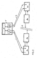
- FIG. 2 can in the case of a line interruption 4, for example, between the secondary participants 2b and 2c, the invention be used to maintain the traffic between the secondary participants 2b and 2c on the main participant 1 upright.
- the annular communication network breaks down into a line-shaped topology, with the main participant 1 forming, together with the secondary participants 2a and 2b, a first partial line and the main participant 1 together with the secondary participants 2c and 2d forming a second partial line.
- the secondary participant 2a could now as well as the secondary participant 2b by means of the above-described data forwarding function of the main participant 1 with the secondary participant 2c and / or 2d communicate.
- the detour via the main subscriber 1 is thus selected, whereby a communication is maintained despite the error.
- the main participant 1 exchanges thus exclusively cross-communication data (user data, which are exclusively exchanged between secondary participants and no data for the main participant as such) at a line break between the secondary participants in accordance with a transmission cycle and focuses only on those required for cross-communication between the secondary participants Data, which makes the process more efficient, because the data volume is much lower in this case.
- the communication network could also be designed so that only those secondary participants 2b, 2c, which of the Line interruption 4 are directly affected, communicate by means of the main participant 1 by a secondary participant 2b, 2c detects a physical interruption 4 in the communication network and reports this interruption to the main participant 1 by means of the still functioning partial line to which it is connected.
- the secondary users 2a and 2b, and 2c and 2d would still communicate with each other directly as in the faultless case.
- the data between these sub-participants are thus excluded from the data stream that passes through the main participant 1. This reduces the amount of data to be processed by the main subscriber and additionally increases the efficiency of the network.
- main participant 1 can process data in such a way that they can be distinguished from data exchanged directly between secondary participants.
- the secondary participants 2a, b, c, d are then able, if necessary, to perform a data postprocessing in order, for example, to correct runtime errors.
- the main station 1 knows in this case the error location and is informed about which slave stations can no longer communicate directly with each other.
- the main station 1 could copy the cross-communication data from one termination 1a to the other terminal 1b and vice versa, so that both data paths, i. the direct communication between the secondary participants and the indirect communication via the main participant is available.
- the computing power available in the main subscriber 1 and the secondary subscribers 2 a, b, c, d can thus be used in an application-specific manner.
- the bidirectional connection lines 3 are preferably based on Ethernet technology (copper lines) or on optical waveguide technology.
- the use of common protocols within the current fieldbus standards provides access to the world of Automation technology, so that as the main participant 1, for example, an electrical control and as secondary participants 2a, 2b, 2c, 2d electrical controls and / or electrical drive controller may be included.
- the inventive concept increases the availability of the machines, which are realized by means of the drive system.
- the secondary participants implemented by means of control systems represent so-called substations and the main participant a so-called head station.
- controllers in ring or line form can be connected. This is also possible at the head end itself, but this preferably takes over central tasks.
- the in the FIGS. 1 and 2 The headend shown only performs higher-level, distributed control tasks, while the substations perform central control tasks.
Abstract
Description
Die Erfindung befasst sich mit einem Verfahren zum Betreiben eines redundanten, ringförmigen Kommunikationsnetzwerkes sowie mit einem Kommunikationsnetzwerk, welches sich dieses Verfahrens bedient.The invention relates to a method for operating a redundant, annular communication network and to a communication network which makes use of this method.
Aus dem Stand der Technik sind ringförmige Kommunikationssysteme mit Redundanzfunktion, die einen Hauptteilnehmer ("Master") und Nebenteilnehmer ("Slaves") umfassen, bekannt. Derartige Kommunikationssysteme sind bspw. in der
Die deutsche Patentanmeldung mit dem Aktenzeichen
Die Aufgabe der Erfindung besteht darin, eine Datenübertragung im Fehlerfalle sicher zu stellen, den Hauptteilnehmer bestmöglich zu entlasten und Laufzeitverzögerungen zwischen Nebenteilnehmern weitestgehend zu vermeiden.The object of the invention is to ensure a data transmission in the event of an error, to relieve the main participant as best as possible and to avoid propagation delays between secondary participants as far as possible.
Gelöst wird die Aufgabe mittels eines Verfahrens zum Betreiben eines redundanten, ringförmigen, insbesondere gegenläufig kommunizierenden, Kommunikationsnetzwerkes mit zumindest einem Hauptteilnehmer und zumindest zwei Nebenteilnehmern, welche mittels einer Datenübertragungseinrichtung miteinander kommunizieren, wobei die Nebenteilnehmer unmittelbar mittels der Datenübertragungseinrichtung miteinander kommunizieren und/oder mittelbar mittels des Hauptteilnehmers und der Datenübertragungseinrichtung miteinander kommunizieren, indem der Hauptteilnehmer die zwischen den Nebenteilnehmern auszutauschenden Daten zwischen seinen Datenübertragungseinrichtungsanschlüssen, insbesondere nach Maßgabe eines Übertragungstaktes, austauscht.The object is achieved by means of a method for operating a redundant, annular, in particular countercommunicating, communication network with at least one main participant and at least two secondary participants, which communicate with each other by means of a data transmission device, wherein the secondary participants communicate directly by means of the data transmission device and / or indirectly by means of the Main participant and the data transmission device communicate with each other by the main participant exchanges the data to be exchanged between the secondary participants between its data transmission device terminals, in particular in accordance with a transmission clock.
Die Datenübertragungseinrichtung könnte beispielsweise mittels einer leitungs-oder funkgebundenen Datenübertragung realisiert sein, welche eine bidirektionale Kommunikation zulässt. Bei den Datenübertragungseinrichtungsanschlüssen des Hauptteilnehmers handelt es sich um die Schnittstellen zwischen Hauptteilnehmer und Datenübertragungseinrichtung. Da es sich um ein ringförmiges, redundantes System handelt, umfasst jeder Teilnehmer (Nebenteilnehmer und Hauptteilnehmer) vier Anschlüsse für die Datenübertragungseinrichtung (jeweils 2 Eingänge und 2 Ausgänge). Die Erfindung schafft ein redundantes und fehlersicheres System, weil die Nebenteilnehmer unabhängig vom Hauptteilnehmer unmittelbar miteinander kommunizieren können, wodurch sie diesen entlasten. Unmittelbar benachbarte Nebenteilnehmer kommunizieren somit auf dem kürzesten Weg miteinander, dies reduziert die Laufzeit der Daten. Zusätzlich besteht im Falle einer Funktionsstörung der Datenübertragungseinrichtung für die Nebenteilnehmer trotzdem noch die Möglichkeit mittels des Hauptteilnehmers zu kommunizieren.The data transmission device could, for example, be realized by means of a line-bound or radio-bound data transmission, which permits bidirectional communication. The subscriber's data transmission device ports are the interfaces between the main subscriber and the data communication device. Since it is a ring-shaped, redundant system, each participant (secondary participant and main participant) comprises four connections for the data transmission device (2 inputs and 2 outputs each). The invention provides a redundant and fail-safe system, because the secondary participants can communicate directly with each other independently of the main participant, thereby relieving them. Immediately adjacent participants thus communicate with each other on the shortest path, this reduces the duration of the data. In addition, in the case of a malfunction of the data transmission device for the secondary participants still has the opportunity to communicate by means of the main participant.
Vorzugsweise tauscht der Hauptteilnehmer ausschließlich bei einer Unterbrechung der Datenübertragung zwischen zwei Nebenteilnehmern alle von den Nebenteilnehmern gesendeten Daten nach Maßgabe eines Übertragungstaktes zwischen Nebenteilnehmern aus. Hierbei werden auch Daten von Nebenteilnehmern berücksichtigt, welche nicht von der Störung betroffen sind. Das bedeutet, sobald ein Fehler in der Doppelringtopologie vorliegt, beginnt die Hauptstation, alle Daten von Nebenstationen, welche am ersten Datenübertragungseinrichtungsanschluss angeschlossen sind, auf den zweiten Datenübertragungseinrichtungsanschluss, an dem weitere Nebenstationen angeschlossen sind, zu übertragen und umgekehrt. Damit wird sichergestellt, dass jeder Nebenteilnehmer aus dem Datenstrom die für ihn bestimmten Daten empfangen kann. Im fehlerfreien Betrieb kommunizieren die Nebenteilnehmer effizient unter Umgehung der Hauptstation unmittelbar miteinander. Die Auslastung der Hauptteilnehmer-CPU wird somit gering gehalten, wobei trotz des Fehlers eine Kommunikation aufrecht erhalten werden kann.Preferably, the main participant exchanges all data sent by the secondary participants in the event of an interruption of the data transmission between two secondary participants in accordance with a transmission cycle between secondary participants. Here are also Takes into account data from other participants who are not affected by the incident. That is, as soon as there is an error in the dual-ring topology, the master station begins to transmit all data from slave stations connected to the first communications gateway port to the second communications gateway port to which other slave stations are connected and vice versa. This ensures that each secondary participant can receive the data intended for him from the data stream. In error-free operation, the secondary participants communicate efficiently with one another bypassing the main station. The utilization of the main user CPU is thus kept low, and despite the error communication can be maintained.
Alternativ tauscht der Hauptteilnehmer ausschließlich Querkommunikationsdaten (von Nebenteilnehmern für Nebenteilnehmer bestimmte Daten) bei einer Störung der Datenüberträgungseinrichtung zwischen den Nebenteilnehmern nach Maßgabe eines Übertragungstaktes aus. Es werden nun nicht mehr alle von den Nebenteilnehmern gesendeten Daten ausgetauscht, die auch Daten für einen Hauptteilnehmer enthalten könnten, sondern nur noch diejenigen Daten, welche tatsächlich auch für andere Nebenteilnehmer bestimmt sind. Daten, welche zwischen Nebenteilnehmer und Hauptteilnehmer auszutauschen sind, werden somit nicht für andere Nebenteilnehmer zugänglich gemacht. Das Verfahren wird dadurch effizienter, denn das Datenaufkommen wird in diesem Falle wesentlich verringert.Alternatively, the main participant exclusively exchanges cross-communication data (data determined by secondary participants for secondary participants) in the event of a disturbance of the data transmission device between the secondary participants in accordance with a transmission cycle. It is no longer exchanged all the data sent by the secondary participants, which could also contain data for a main participant, but only those data that are actually intended for other secondary participants. Data, which are to be exchanged between secondary participant and main participant, are thus not made accessible to other secondary participants. The process becomes more efficient, because the data volume is significantly reduced in this case.
Bevorzugt wird das Verfahren insofern noch verfeinert, als ausschließlich diejenigen Nebenteilnehmer, welche von einer Störung unmittelbar betroffen sind, mittels des Hauptteilnehmers kommunizieren, indem insbesondere diese die Störung erkennen und dem Hauptteilnehmer melden. Im Fehlerfalle lokalisiert die Hauptstation die zu kopierenden Daten anhand des nun bekannten Fehlerortes. Die Hauptstation ermittelt demnach nur diejenigen Daten, die von einer noch funktionsfähigen Teillinie zur anderen noch funktionsfähigen Teillinie des Kommunikationsnetzwerkes (siehe
Erfindungsgemäß bearbeitet der Hauptteilnehmer die zu einem Nebenteilnehmer weitergeleitete Daten derart, dass diese von unmittelbar zwischen Nebenteilnehmern ausgetauschten Daten unterscheidbar sind, beispielsweise durch Manipulation von Datenfeldern innerhalb der der Datenübertragung zugrunde liegenden Datentelegramme. Auch eine derartige Datenbearbeitung durch den Nebenteilnehmer ist denkbar. Dies ist besonders vorteilhaft, weil aufgrund der mittelbaren Datenübertragung über den Hauptteilnehmer eine Laufzeitverzögerung der Datentelegramme resultieren kann. Die von dieser Laufzeitverzögerung betroffenen Daten werden mittels des Hauptteilnehmers nun gesondert markiert, sind somit identifizierbar und gegebenenfalls nachträglich bearbeitbar.According to the invention, the main participant processes the data forwarded to a secondary participant in such a way that they can be distinguished from data exchanged directly between secondary participants, for example by manipulating data fields within the data telegrams on which the data transmission is based. Such data processing by the secondary participant is also conceivable. This is particularly advantageous because, due to the indirect data transmission via the main subscriber, a propagation delay of the data telegrams can result. The data affected by this propagation delay are now marked separately by means of the main participant, are thus identifiable and optionally editable.
Ergänzend zu dem zuvor genannten Verfahrensschritt werden die Daten vorteilhafteniveise durch die Nebenteilnehmer und/oder den Hauptteilnehmer einer zusätzlichen Datenbearbeitung unterzogen. Eine derartige Sonderbehandlung der laufzeitverzögerten Daten, beispielsweise mittels einer Extrapolation, ermöglicht gezielte Laufzeitkorrekturen oder beispielsweise eine Mittelwertbildung. Fehlern im System aufgrund fehlerhafter Daten wird somit vorgebeugt, das System wird stabiler und weniger wartungsanfällig.In addition to the aforementioned method step, the data is advantageously subjected to additional data processing by the secondary participants and / or the main participant. Such a special treatment of the delay-delayed data, for example by means of extrapolation, enables targeted time-of-flight corrections or, for example, an averaging. Errors in the system due to erroneous data is thus prevented, the system becomes more stable and less maintenance-prone.
Vorzugsweise basiert ein leitungsgebundenes Kommunikationsnetzwerk auf dem erfindungsgemäßen Verfahren, wobei dieses auf der Ethernettechnologie oder auf der Lichtwellenleitertechnologie basiert und die Kommunikation auf einer Feldbusnorm basiert. Die Ethernettechnologie ermöglicht eine einfache Handhabung der Verbindungsleitungen, da diese in der Regel auf Kupferleitungen basieren. Ethernet ist erprobt, weniger kostenintensiv und weniger fehleranfällig. Die Lichtwellenleitertechnologie ist unanfällig gegenüber elektromagnetischer Störungen und erhöht die Datensicherheit. Die Realisierung des Kommunikationsnetzwerkes im Rahmen eines Feldbusnetzwerkes (Profibus, SERCOS, CANopen, etc.) ermöglicht den Zugang zur Automatisierungstechnik. Bei Verwendung einer echtzeitfähigen Kommunikation erschließen sich weitere vorteilhafte Anwendungsfelder, insbesondere bei der Verarbeitung zeitkritischer Daten.Preferably, a wired communication network based on the inventive method, this on the Ethernet technology or based on optical fiber technology and the communication is based on a fieldbus standard. The Ethernet technology allows easy handling of the interconnections, as these are usually based on copper lines. Ethernet is proven, less expensive and less error prone. Optical fiber technology is immune to electromagnetic interference and increases data security. The implementation of the communication network in the context of a fieldbus network (Profibus, SERCOS, CANopen, etc.) provides access to automation technology. The use of real-time communication opens up further advantageous application fields, in particular in the processing of time-critical data.
Ganz besonders bevorzugt verwendet ein Antriebssystem, insbesondere für Automatisierungszwecke, ein solches Kommunikationsnetzwerk, wobei dieses als Hauptteilnehmer eine elektrische Steuerung und/oder Antriebsregler und als Nebenteilnehmer elektrische Steuerungen und/oder elektrische Antriebsregler umfasst. Das erfindungsgemäße Konzept erhöht die Verfügbarkeit der vom Automatisierungssystem umfassten Maschinen.Very particularly preferably, a drive system, in particular for automation purposes, uses such a communication network, this comprising as the main participant an electrical control and / or drive controller and as secondary participants electrical controls and / or electrical drive controller. The inventive concept increases the availability of the machines included in the automation system.
Die Erfindung wird anhand der nachfolgend gezeigten konkreten Ausgestaltungsbeispiele näher erläutert. Es zeigen:
-
Figur 1 ein störungsfrei arbeitendes, redundantes Kommunikationsnetzwerk. -
Figur 2 ein störungsbehaftetes, redundantes Kommunikationsnetzwerk.
-
FIG. 1 a trouble-free working, redundant communication network. -
FIG. 2 a faulty, redundant communication network.
Das in
Gemäß
Das Kommunikationsnetzwerk könnte auch so konzipiert sein, dass ausschließlich diejenigen Nebenteilnehmer 2b, 2c, welche von der Leitungsunterbrechung 4 unmittelbar betroffen sind, mittels des Hauptteilnehmers 1 kommunizieren, indem ein Nebenteilnehmer 2b, 2c eine physikalisch bedingte Unterbrechung 4 im Kommunikationsnetzwerk erkennt und diese Unterbrechung dem Hauptteilnehmer 1 mittels der noch funktionsfähigen Teillinie, an der er angeschlossen ist, meldet. Bei dieser Konfiguration würden die Nebenteilnehmer 2a und 2b bzw. 2c und 2d nach wie vor wie im fehlerfreien Fall unmittelbar miteinander kommunizieren. Die Daten zwischen diesen Nebenteilnehmern sind somit von dem Datenstrom ausgenommen, der über den Hauptteilnehmer 1 läuft. Dies reduziert die vom Hauptteilnehmer zu verarbeitende Datenmenge und erhöht die Effizienz des Netzwerkes zusätzlich.The communication network could also be designed so that only those
Der Hauptteilnehmer 1 kann im Falle der Weiterleitung an Nebenteilnehmer 2a,b,c,d Daten derart bearbeiten, dass diese von unmittelbar zwischen Nebenteilnehmern ausgetauschten Daten unterscheidbar sind. Die Nebenteilnehmer 2a,b,c,d sind dann in der Lage, gegebenenfalls einer Datennachbearbeitung zu unterziehen, um beispielsweise Laufzeitfehler zu korrigieren. Die Hauptstation 1 kennt in diesem Falle den Fehlerort und ist darüber informiert welche Nebenstationen nicht mehr direkt miteinander kommunizieren können.In the case of forwarding to
Auch im fehlerfreien Falle könnte die Hauptstation 1 die Querkommunikationsdaten von einem Abschluss 1 a zum anderen Anschluss 1b und umgekehrt kopieren, so dass beide Datenpfade, d.h. die unmittelbare Kommunikation zwischen den Nebenteilnehmern und die mittelbare Kommunikation über den Hauptteilnehmer, zur Verfügung steht. Die im Hauptteilnehmer 1 und den Nebenteilnehmern 2a, b, c, d zur Verfügung stehende Rechenleistung kann somit anwendungsspezifisch genutzt werden.Even in the error-free case, the main station 1 could copy the cross-communication data from one termination 1a to the other terminal 1b and vice versa, so that both data paths, i. the direct communication between the secondary participants and the indirect communication via the main participant is available. The computing power available in the main subscriber 1 and the
Die bidirektionalen Verbindungsleitungen 3 basieren vorzugsweise auf der Ethernettechnologie (Kupferleitungen) oder auf der Lichtwellenleitertechnologie. Die Verwendung von im Rahmen der gängigen Feldbusnormen üblichen Protokollen (Profibus, SERCOS I, II, III) ermöglicht den Zugang zur Welt der Automatisierungstechnik, so dass als Hauptteilnehmer 1 beispielsweise eine elektrische Steuerung und als Nebenteilnehmer 2a, 2b, 2c, 2d elektrische Steuerungen und/oder elektrische Antriebsregler umfasst sein können. Das erfindungsgemäße Konzept erhöht die Verfügbarkeit der Maschinen, welche mittels des Antriebssystems realisiert sind.The
Die mittels Steuerungen realisierten Nebenteilnehmer stellen so genannte Unterstationen und der Hauptteilnehmer eine so genannte Kopfstation dar. An jeder Unterstation können Antriebsregler in Ring- oder Linienform angeschlossen sein. Auch an der Kopfstation selbst ist das möglich, wobei diese jedoch bevorzugt zentrale Aufgaben übernimmt. Die in den
- 11
- Hauptteilnehmermain participants
- 1a1a
- Anschluss (Eingang- und Ausgang) 1Connection (input and output) 1
- 1b1b
- Anschluss (Eingang- und Ausgang) 2Connection (input and output) 2
- 1c1c
- Datenverarbeitungdata processing
- 2a,b,c,d2a, b, c, d
- NebenteilnehmerIn addition to participants
- 33
- Verbindungsleitungconnecting line
- 44
- Unterbrechunginterruption
Claims (12)
Applications Claiming Priority (2)
| Application Number | Priority Date | Filing Date | Title |
|---|---|---|---|
| DE102006004339A DE102006004339A1 (en) | 2006-01-30 | 2006-01-30 | Redundant communication network |
| EP07001438.6A EP1814266B1 (en) | 2006-01-30 | 2007-01-24 | Redundant communications network |
Related Parent Applications (3)
| Application Number | Title | Priority Date | Filing Date |
|---|---|---|---|
| EP07001438.6A Division-Into EP1814266B1 (en) | 2006-01-30 | 2007-01-24 | Redundant communications network |
| EP07001438.6A Division EP1814266B1 (en) | 2006-01-30 | 2007-01-24 | Redundant communications network |
| EP07001438.6 Division | 2007-01-24 |
Publications (2)
| Publication Number | Publication Date |
|---|---|
| EP2096799A1 true EP2096799A1 (en) | 2009-09-02 |
| EP2096799B1 EP2096799B1 (en) | 2011-01-19 |
Family
ID=38006864
Family Applications (2)
| Application Number | Title | Priority Date | Filing Date |
|---|---|---|---|
| EP07001438.6A Not-in-force EP1814266B1 (en) | 2006-01-30 | 2007-01-24 | Redundant communications network |
| EP09006695A Not-in-force EP2096799B1 (en) | 2006-01-30 | 2007-01-24 | Redundant communications network |
Family Applications Before (1)
| Application Number | Title | Priority Date | Filing Date |
|---|---|---|---|
| EP07001438.6A Not-in-force EP1814266B1 (en) | 2006-01-30 | 2007-01-24 | Redundant communications network |
Country Status (5)
| Country | Link |
|---|---|
| US (1) | US8559300B2 (en) |
| EP (2) | EP1814266B1 (en) |
| JP (1) | JP5150105B2 (en) |
| AT (1) | ATE496456T1 (en) |
| DE (2) | DE102006004339A1 (en) |
Families Citing this family (10)
| Publication number | Priority date | Publication date | Assignee | Title |
|---|---|---|---|---|
| DE102004055330A1 (en) * | 2004-11-16 | 2006-05-24 | Bosch Rexroth Aktiengesellschaft | Method and device for operating a network |
| DE102005016596A1 (en) * | 2005-04-11 | 2006-10-19 | Beckhoff Automation Gmbh | Subscriber, master unit, communication system and method of operating the same |
| DE102006018884A1 (en) * | 2006-04-24 | 2007-10-25 | Beckhoff Automation Gmbh | Interface unit and communication system with a master-slave structure |
| CN101132328A (en) * | 2007-08-15 | 2008-02-27 | 北京航空航天大学 | Real-time industry Ethernet EtherCAT communication controller |
| KR101720347B1 (en) * | 2011-01-20 | 2017-03-27 | 엘에스산전 주식회사 | Adaptive multi redundant ring topology system and Method for selecting the detour |
| DE102012000474C5 (en) | 2012-01-13 | 2023-10-05 | Robert Bosch Gmbh | Device and method for wireless point-to-point connection in an automation system and automation system |
| US9860304B2 (en) | 2014-01-21 | 2018-01-02 | Woodward, Inc. | Redundant CAN interface for dual actuation systems |
| EP3477896B1 (en) * | 2017-10-26 | 2020-02-19 | Mitsubishi Electric R&D Centre Europe B.V. | Efficient scheduling telecommunication scheme using a first cyclic ethernet protocol and a second cyclic ethernet protocol |
| CN110474299B (en) * | 2019-08-15 | 2022-04-15 | 荣信汇科电气股份有限公司 | Bypass state cycle reporting method and topology structure of power unit |
| DE102020207794A1 (en) | 2020-06-24 | 2021-12-30 | Robert Bosch Gesellschaft mit beschränkter Haftung | Method for operating a communication system and communication system |
Citations (12)
| Publication number | Priority date | Publication date | Assignee | Title |
|---|---|---|---|---|
| DE19637312A1 (en) * | 1996-09-12 | 1998-03-19 | Bosch Gmbh Robert | Method for checking the connections of a transmission system and component for carrying out the method |
| DE19803686A1 (en) * | 1998-01-30 | 1999-08-05 | Siemens Ag | Method and device for the communication of equal stations of a ring-shaped, serial optical fiber bus |
| EP0980166A1 (en) * | 1998-08-06 | 2000-02-16 | Siemens Aktiengesellschaft | Active publishing |
| DE19904894A1 (en) * | 1999-02-06 | 2000-08-17 | Peter Wratil | Slave to slave communication method for circular local network for automated processes, involves using decentralized units |
| DE19927635A1 (en) * | 1999-06-17 | 2001-01-04 | Phoenix Contact Gmbh & Co | Safety-related automation bus system |
| EP1075110A2 (en) * | 1999-07-28 | 2001-02-07 | PHOENIX CONTACT GmbH & Co. | Combined master/slave-producer/consumer communication method for a network |
| EP1133106A2 (en) * | 2000-02-12 | 2001-09-12 | PHOENIX CONTACT GmbH & Co. | Device for controlling the data exchange in a communication terminal |
| WO2003049366A2 (en) * | 2001-11-30 | 2003-06-12 | Siemens Aktiengesellschaft | Arrangement with a measuring transducer and at least one sensor connected in common to a process controller by means of a field bus |
| WO2003073704A1 (en) | 2002-02-22 | 2003-09-04 | Siemens Aktiengesellschaft | Local network, particularly ethernet network having redundancy properties, and redundancy manager for such a network |
| US20040223503A1 (en) | 2003-05-06 | 2004-11-11 | Overture Networks, Inc. | Protected switching ring |
| EP1585266A2 (en) * | 2004-03-24 | 2005-10-12 | Bosch Rexroth AG | Method for transferring data |
| DE102004041093A1 (en) | 2004-08-24 | 2006-03-09 | Bosch Rexroth Aktiengesellschaft | Main station and slave station in a network and a method for transmitting data in a network |
Family Cites Families (14)
| Publication number | Priority date | Publication date | Assignee | Title |
|---|---|---|---|---|
| US4539655A (en) * | 1982-03-16 | 1985-09-03 | Phoenix Digital Corporation | Microcomputer based distributed control network |
| JPS5940739A (en) * | 1982-08-30 | 1984-03-06 | Fujitsu Ltd | Loopback control system |
| JPH03123244A (en) * | 1989-10-06 | 1991-05-27 | Matsushita Electric Ind Co Ltd | Communication equipment |
| DE19810587A1 (en) * | 1998-03-11 | 1999-09-16 | Siemens Ag | Ethernet (RTM) network with redundancy characteristics |
| JP2000115202A (en) * | 1998-09-30 | 2000-04-21 | Omron Corp | Network connector and communication control method |
| US6594232B1 (en) * | 1999-06-02 | 2003-07-15 | Marconi Communications, Inc. | Transmitter-based path protection switching in a ring network |
| US7657330B2 (en) * | 1999-06-11 | 2010-02-02 | Parker-Hannifin Corporation | Optical ring architecture |
| DE10047923C2 (en) * | 2000-09-27 | 2003-04-10 | Siemens Ag | Method for generating a connection redundancy for a serial communication system with a master unit and a plurality of slave units, which are connected to one another as a series of point-to-point connections in line topology, and a corresponding serial communication system |
| US7024257B2 (en) * | 2001-02-09 | 2006-04-04 | Motion Engineering, Inc. | System for motion control, method of using the system for motion control, and computer-readable instructions for use with the system for motion control |
| US7142504B1 (en) * | 2001-04-25 | 2006-11-28 | Cisco Technology, Inc. | Fault tolerant network traffic management |
| US6766482B1 (en) * | 2001-10-31 | 2004-07-20 | Extreme Networks | Ethernet automatic protection switching |
| JP3717460B2 (en) * | 2002-06-07 | 2005-11-16 | ボーダフォン株式会社 | Network, network center and network device |
| US7599315B2 (en) * | 2002-12-16 | 2009-10-06 | Alcatel-Lucent Canada Inc. | Topology discovery in a dual ring network |
| US7515531B2 (en) * | 2004-08-17 | 2009-04-07 | Cox Communications | Apparatus and methods for the communication and fault management of data in a multipath data network |
-
2006
- 2006-01-30 DE DE102006004339A patent/DE102006004339A1/en not_active Withdrawn
-
2007
- 2007-01-24 EP EP07001438.6A patent/EP1814266B1/en not_active Not-in-force
- 2007-01-24 AT AT09006695T patent/ATE496456T1/en active
- 2007-01-24 DE DE502007006334T patent/DE502007006334D1/en active Active
- 2007-01-24 EP EP09006695A patent/EP2096799B1/en not_active Not-in-force
- 2007-01-25 US US11/627,127 patent/US8559300B2/en not_active Expired - Fee Related
- 2007-01-30 JP JP2007019561A patent/JP5150105B2/en not_active Expired - Fee Related
Patent Citations (12)
| Publication number | Priority date | Publication date | Assignee | Title |
|---|---|---|---|---|
| DE19637312A1 (en) * | 1996-09-12 | 1998-03-19 | Bosch Gmbh Robert | Method for checking the connections of a transmission system and component for carrying out the method |
| DE19803686A1 (en) * | 1998-01-30 | 1999-08-05 | Siemens Ag | Method and device for the communication of equal stations of a ring-shaped, serial optical fiber bus |
| EP0980166A1 (en) * | 1998-08-06 | 2000-02-16 | Siemens Aktiengesellschaft | Active publishing |
| DE19904894A1 (en) * | 1999-02-06 | 2000-08-17 | Peter Wratil | Slave to slave communication method for circular local network for automated processes, involves using decentralized units |
| DE19927635A1 (en) * | 1999-06-17 | 2001-01-04 | Phoenix Contact Gmbh & Co | Safety-related automation bus system |
| EP1075110A2 (en) * | 1999-07-28 | 2001-02-07 | PHOENIX CONTACT GmbH & Co. | Combined master/slave-producer/consumer communication method for a network |
| EP1133106A2 (en) * | 2000-02-12 | 2001-09-12 | PHOENIX CONTACT GmbH & Co. | Device for controlling the data exchange in a communication terminal |
| WO2003049366A2 (en) * | 2001-11-30 | 2003-06-12 | Siemens Aktiengesellschaft | Arrangement with a measuring transducer and at least one sensor connected in common to a process controller by means of a field bus |
| WO2003073704A1 (en) | 2002-02-22 | 2003-09-04 | Siemens Aktiengesellschaft | Local network, particularly ethernet network having redundancy properties, and redundancy manager for such a network |
| US20040223503A1 (en) | 2003-05-06 | 2004-11-11 | Overture Networks, Inc. | Protected switching ring |
| EP1585266A2 (en) * | 2004-03-24 | 2005-10-12 | Bosch Rexroth AG | Method for transferring data |
| DE102004041093A1 (en) | 2004-08-24 | 2006-03-09 | Bosch Rexroth Aktiengesellschaft | Main station and slave station in a network and a method for transmitting data in a network |
Non-Patent Citations (4)
| Title |
|---|
| INTERESSENSGEMEINSCHAFT SERCOS INTERFACE E V: "SERCOS-III (Dritte Generation SERCOS interface)", INTERNET CITATION, April 2004 (2004-04-01), XP002356906, Retrieved from the Internet <URL:http://www.sercos.de/pdf/SERCOS-III_V134d_public.pdf> [retrieved on 20051201] * |
| SCHEMM, EBERHARD: "Innovation durch Kombination", PRAXIS PROFILINE - SERCOS INTERFACE, 31 May 2004 (2004-05-31), Vogel Verlag, Würzburg, pages 26 - 28, XP002444455, ISBN: 3-8259-1926-9 * |
| SCHWEINZER H ET AL: "Shared Data on Interbus", INTERNET CITATION, XP002269738, Retrieved from the Internet <URL:http://www.ict.tuwien.ac.at/komzent/interbus/SharedData.pdf> [retrieved on 20040210] * |
| TUERKE C: "INTERBUS-S IN DER REGELSCHLEIFE. DATENTRANSFER VON SLAVE ZU SLAVE MACHT'S MOEGLICH", ELEKTRONIK, WEKA FACHZEITSCHRIFTENVERLAG, POING, DE, vol. 44, no. 12, 13 June 1995 (1995-06-13), pages 79,81 - 84, XP000515422, ISSN: 0013-5658 * |
Also Published As
| Publication number | Publication date |
|---|---|
| JP5150105B2 (en) | 2013-02-20 |
| US20070192449A1 (en) | 2007-08-16 |
| EP1814266A2 (en) | 2007-08-01 |
| EP1814266A3 (en) | 2008-02-06 |
| EP1814266B1 (en) | 2014-03-26 |
| EP2096799B1 (en) | 2011-01-19 |
| JP2007208982A (en) | 2007-08-16 |
| DE502007006334D1 (en) | 2011-03-03 |
| US8559300B2 (en) | 2013-10-15 |
| DE102006004339A1 (en) | 2007-08-02 |
| ATE496456T1 (en) | 2011-02-15 |
Similar Documents
| Publication | Publication Date | Title |
|---|---|---|
| EP1814266B1 (en) | Redundant communications network | |
| EP2098018B1 (en) | Communication system having a master/slave structure | |
| EP2098019B1 (en) | Communication system having a master/slave structure | |
| EP1869836B1 (en) | Master unit communication system and method for operation thereof | |
| EP1748338B1 (en) | Method for optimizing bandwidth usage in bus systems | |
| EP1657608B1 (en) | Method and apparatus for operating a network | |
| EP2866387B1 (en) | Bus system and method for operating such a bus system | |
| EP2838220B1 (en) | Method for the redundant transmission of messages in an industrial communication network and communication device | |
| DE102009042354B4 (en) | Method and device for safety-related communication in the communication network of an automation system | |
| EP2014025B1 (en) | Interface unit and communication system having a master/slave structure | |
| EP1789857B1 (en) | Data transfer method and automation system used in said data transfer method | |
| EP2981868B1 (en) | Control and data transmission system, process device and method for redundant process control with decentralized redundancy | |
| EP2438722B1 (en) | Data transfer device for remote-control and remote-monitoring of a distributed processing system | |
| DE102008050102A1 (en) | Communication entity for communication via a bus-oriented communication network | |
| EP2713563B1 (en) | Redundant industrial communication system, communication apparatus and method for redundant operation of an industrial communication system | |
| WO2016008948A1 (en) | Control and data-transfer system, gateway module, i/o module, and method for process control | |
| DE102015105929A1 (en) | Automation device for redundantly controlling a bus subscriber | |
| EP1609273A2 (en) | Communication system with redundant communication | |
| EP1193916A2 (en) | Link redundancy for a serial communication system | |
| DE102004044764A1 (en) | Transmission of data packets between two devices in automation system, using check symbol from last data packet received as start value when calculating check symbols for packet to be sent | |
| EP2817923B1 (en) | Computer network with a ring bus connection | |
| EP2182680B1 (en) | Method for operating a communication network and communication components | |
| DE102014201373A1 (en) | Method for operating a redundant communication network | |
| EP2750340A1 (en) | Method for message communication in a redundant operated industrial communication network and network infrastructure device |
Legal Events
| Date | Code | Title | Description |
|---|---|---|---|
| PUAI | Public reference made under article 153(3) epc to a published international application that has entered the european phase |
Free format text: ORIGINAL CODE: 0009012 |
|
| AC | Divisional application: reference to earlier application |
Ref document number: 1814266 Country of ref document: EP Kind code of ref document: P |
|
| AK | Designated contracting states |
Kind code of ref document: A1 Designated state(s): AT BE BG CH CY CZ DE DK EE ES FI FR GB GR HU IE IS IT LI LT LU LV MC NL PL PT RO SE SI SK TR |
|
| RIN1 | Information on inventor provided before grant (corrected) |
Inventor name: SCHULTZE, STEPHAN DR. Inventor name: NOACK, GERALD Inventor name: ACKERMANN, ROLAND Inventor name: TCHEKLER, ALEXANDER |
|
| 17P | Request for examination filed |
Effective date: 20100302 |
|
| 17Q | First examination report despatched |
Effective date: 20100323 |
|
| GRAP | Despatch of communication of intention to grant a patent |
Free format text: ORIGINAL CODE: EPIDOSNIGR1 |
|
| GRAS | Grant fee paid |
Free format text: ORIGINAL CODE: EPIDOSNIGR3 |
|
| GRAA | (expected) grant |
Free format text: ORIGINAL CODE: 0009210 |
|
| AC | Divisional application: reference to earlier application |
Ref document number: 1814266 Country of ref document: EP Kind code of ref document: P |
|
| AK | Designated contracting states |
Kind code of ref document: B1 Designated state(s): AT BE BG CH CY CZ DE DK EE ES FI FR GB GR HU IE IS IT LI LT LU LV MC NL PL PT RO SE SI SK TR |
|
| REG | Reference to a national code |
Ref country code: GB Ref legal event code: FG4D Free format text: NOT ENGLISH |
|
| REG | Reference to a national code |
Ref country code: CH Ref legal event code: EP |
|
| REG | Reference to a national code |
Ref country code: IE Ref legal event code: FG4D Free format text: LANGUAGE OF EP DOCUMENT: GERMAN |
|
| REF | Corresponds to: |
Ref document number: 502007006334 Country of ref document: DE Date of ref document: 20110303 Kind code of ref document: P |
|
| REG | Reference to a national code |
Ref country code: DE Ref legal event code: R096 Ref document number: 502007006334 Country of ref document: DE Effective date: 20110303 |
|
| REG | Reference to a national code |
Ref country code: NL Ref legal event code: VDEP Effective date: 20110119 |
|
| LTIE | Lt: invalidation of european patent or patent extension |
Effective date: 20110119 |
|
| PG25 | Lapsed in a contracting state [announced via postgrant information from national office to epo] |
Ref country code: LT Free format text: LAPSE BECAUSE OF FAILURE TO SUBMIT A TRANSLATION OF THE DESCRIPTION OR TO PAY THE FEE WITHIN THE PRESCRIBED TIME-LIMIT Effective date: 20110119 Ref country code: IS Free format text: LAPSE BECAUSE OF FAILURE TO SUBMIT A TRANSLATION OF THE DESCRIPTION OR TO PAY THE FEE WITHIN THE PRESCRIBED TIME-LIMIT Effective date: 20110519 Ref country code: PT Free format text: LAPSE BECAUSE OF FAILURE TO SUBMIT A TRANSLATION OF THE DESCRIPTION OR TO PAY THE FEE WITHIN THE PRESCRIBED TIME-LIMIT Effective date: 20110519 Ref country code: SE Free format text: LAPSE BECAUSE OF FAILURE TO SUBMIT A TRANSLATION OF THE DESCRIPTION OR TO PAY THE FEE WITHIN THE PRESCRIBED TIME-LIMIT Effective date: 20110119 Ref country code: GR Free format text: LAPSE BECAUSE OF FAILURE TO SUBMIT A TRANSLATION OF THE DESCRIPTION OR TO PAY THE FEE WITHIN THE PRESCRIBED TIME-LIMIT Effective date: 20110420 Ref country code: LV Free format text: LAPSE BECAUSE OF FAILURE TO SUBMIT A TRANSLATION OF THE DESCRIPTION OR TO PAY THE FEE WITHIN THE PRESCRIBED TIME-LIMIT Effective date: 20110119 Ref country code: ES Free format text: LAPSE BECAUSE OF FAILURE TO SUBMIT A TRANSLATION OF THE DESCRIPTION OR TO PAY THE FEE WITHIN THE PRESCRIBED TIME-LIMIT Effective date: 20110430 |
|
| BERE | Be: lapsed |
Owner name: ROBERT BOSCH G.M.B.H. Effective date: 20110131 |
|
| REG | Reference to a national code |
Ref country code: IE Ref legal event code: FD4D |
|
| PG25 | Lapsed in a contracting state [announced via postgrant information from national office to epo] |
Ref country code: NL Free format text: LAPSE BECAUSE OF FAILURE TO SUBMIT A TRANSLATION OF THE DESCRIPTION OR TO PAY THE FEE WITHIN THE PRESCRIBED TIME-LIMIT Effective date: 20110119 Ref country code: CY Free format text: LAPSE BECAUSE OF FAILURE TO SUBMIT A TRANSLATION OF THE DESCRIPTION OR TO PAY THE FEE WITHIN THE PRESCRIBED TIME-LIMIT Effective date: 20110119 Ref country code: SI Free format text: LAPSE BECAUSE OF FAILURE TO SUBMIT A TRANSLATION OF THE DESCRIPTION OR TO PAY THE FEE WITHIN THE PRESCRIBED TIME-LIMIT Effective date: 20110119 Ref country code: PL Free format text: LAPSE BECAUSE OF FAILURE TO SUBMIT A TRANSLATION OF THE DESCRIPTION OR TO PAY THE FEE WITHIN THE PRESCRIBED TIME-LIMIT Effective date: 20110119 Ref country code: BG Free format text: LAPSE BECAUSE OF FAILURE TO SUBMIT A TRANSLATION OF THE DESCRIPTION OR TO PAY THE FEE WITHIN THE PRESCRIBED TIME-LIMIT Effective date: 20110419 Ref country code: FI Free format text: LAPSE BECAUSE OF FAILURE TO SUBMIT A TRANSLATION OF THE DESCRIPTION OR TO PAY THE FEE WITHIN THE PRESCRIBED TIME-LIMIT Effective date: 20110119 Ref country code: MC Free format text: LAPSE BECAUSE OF NON-PAYMENT OF DUE FEES Effective date: 20110131 |
|
| PG25 | Lapsed in a contracting state [announced via postgrant information from national office to epo] |
Ref country code: IE Free format text: LAPSE BECAUSE OF FAILURE TO SUBMIT A TRANSLATION OF THE DESCRIPTION OR TO PAY THE FEE WITHIN THE PRESCRIBED TIME-LIMIT Effective date: 20110119 Ref country code: EE Free format text: LAPSE BECAUSE OF FAILURE TO SUBMIT A TRANSLATION OF THE DESCRIPTION OR TO PAY THE FEE WITHIN THE PRESCRIBED TIME-LIMIT Effective date: 20110119 Ref country code: DK Free format text: LAPSE BECAUSE OF FAILURE TO SUBMIT A TRANSLATION OF THE DESCRIPTION OR TO PAY THE FEE WITHIN THE PRESCRIBED TIME-LIMIT Effective date: 20110119 |
|
| PLBE | No opposition filed within time limit |
Free format text: ORIGINAL CODE: 0009261 |
|
| STAA | Information on the status of an ep patent application or granted ep patent |
Free format text: STATUS: NO OPPOSITION FILED WITHIN TIME LIMIT |
|
| PG25 | Lapsed in a contracting state [announced via postgrant information from national office to epo] |
Ref country code: RO Free format text: LAPSE BECAUSE OF FAILURE TO SUBMIT A TRANSLATION OF THE DESCRIPTION OR TO PAY THE FEE WITHIN THE PRESCRIBED TIME-LIMIT Effective date: 20110119 Ref country code: CZ Free format text: LAPSE BECAUSE OF FAILURE TO SUBMIT A TRANSLATION OF THE DESCRIPTION OR TO PAY THE FEE WITHIN THE PRESCRIBED TIME-LIMIT Effective date: 20110119 Ref country code: BE Free format text: LAPSE BECAUSE OF NON-PAYMENT OF DUE FEES Effective date: 20110131 Ref country code: SK Free format text: LAPSE BECAUSE OF FAILURE TO SUBMIT A TRANSLATION OF THE DESCRIPTION OR TO PAY THE FEE WITHIN THE PRESCRIBED TIME-LIMIT Effective date: 20110119 |
|
| REG | Reference to a national code |
Ref country code: DE Ref legal event code: R119 Ref document number: 502007006334 Country of ref document: DE Effective date: 20110802 |
|
| 26N | No opposition filed |
Effective date: 20111020 |
|
| PG25 | Lapsed in a contracting state [announced via postgrant information from national office to epo] |
Ref country code: IT Free format text: LAPSE BECAUSE OF FAILURE TO SUBMIT A TRANSLATION OF THE DESCRIPTION OR TO PAY THE FEE WITHIN THE PRESCRIBED TIME-LIMIT Effective date: 20110119 |
|
| PGFP | Annual fee paid to national office [announced via postgrant information from national office to epo] |
Ref country code: GB Payment date: 20130122 Year of fee payment: 7 Ref country code: CH Payment date: 20130123 Year of fee payment: 7 Ref country code: FR Payment date: 20130207 Year of fee payment: 7 |
|
| PG25 | Lapsed in a contracting state [announced via postgrant information from national office to epo] |
Ref country code: LU Free format text: LAPSE BECAUSE OF NON-PAYMENT OF DUE FEES Effective date: 20110124 |
|
| PG25 | Lapsed in a contracting state [announced via postgrant information from national office to epo] |
Ref country code: DE Free format text: LAPSE BECAUSE OF NON-PAYMENT OF DUE FEES Effective date: 20110802 |
|
| PG25 | Lapsed in a contracting state [announced via postgrant information from national office to epo] |
Ref country code: TR Free format text: LAPSE BECAUSE OF FAILURE TO SUBMIT A TRANSLATION OF THE DESCRIPTION OR TO PAY THE FEE WITHIN THE PRESCRIBED TIME-LIMIT Effective date: 20110119 |
|
| PG25 | Lapsed in a contracting state [announced via postgrant information from national office to epo] |
Ref country code: HU Free format text: LAPSE BECAUSE OF FAILURE TO SUBMIT A TRANSLATION OF THE DESCRIPTION OR TO PAY THE FEE WITHIN THE PRESCRIBED TIME-LIMIT Effective date: 20110119 |
|
| REG | Reference to a national code |
Ref country code: CH Ref legal event code: PL |
|
| GBPC | Gb: european patent ceased through non-payment of renewal fee |
Effective date: 20140124 |
|
| PG25 | Lapsed in a contracting state [announced via postgrant information from national office to epo] |
Ref country code: CH Free format text: LAPSE BECAUSE OF NON-PAYMENT OF DUE FEES Effective date: 20140131 Ref country code: LI Free format text: LAPSE BECAUSE OF NON-PAYMENT OF DUE FEES Effective date: 20140131 |
|
| REG | Reference to a national code |
Ref country code: FR Ref legal event code: ST Effective date: 20140930 |
|
| PG25 | Lapsed in a contracting state [announced via postgrant information from national office to epo] |
Ref country code: GB Free format text: LAPSE BECAUSE OF NON-PAYMENT OF DUE FEES Effective date: 20140124 Ref country code: FR Free format text: LAPSE BECAUSE OF NON-PAYMENT OF DUE FEES Effective date: 20140131 |
|
| PGFP | Annual fee paid to national office [announced via postgrant information from national office to epo] |
Ref country code: AT Payment date: 20160120 Year of fee payment: 10 |
|
| REG | Reference to a national code |
Ref country code: AT Ref legal event code: MM01 Ref document number: 496456 Country of ref document: AT Kind code of ref document: T Effective date: 20170124 |
|
| PG25 | Lapsed in a contracting state [announced via postgrant information from national office to epo] |
Ref country code: AT Free format text: LAPSE BECAUSE OF NON-PAYMENT OF DUE FEES Effective date: 20170124 |