EP2067020B1 - Luminescence microscopy with enhanced resolution - Google Patents
Luminescence microscopy with enhanced resolution Download PDFInfo
- Publication number
- EP2067020B1 EP2067020B1 EP07802252A EP07802252A EP2067020B1 EP 2067020 B1 EP2067020 B1 EP 2067020B1 EP 07802252 A EP07802252 A EP 07802252A EP 07802252 A EP07802252 A EP 07802252A EP 2067020 B1 EP2067020 B1 EP 2067020B1
- Authority
- EP
- European Patent Office
- Prior art keywords
- sample
- laser radiation
- luminescence
- frequency
- radiation
- Prior art date
- Legal status (The legal status is an assumption and is not a legal conclusion. Google has not performed a legal analysis and makes no representation as to the accuracy of the status listed.)
- Active
Links
- 238000004020 luminiscence type Methods 0.000 title claims abstract description 32
- 238000000386 microscopy Methods 0.000 title claims abstract description 13
- 230000005855 radiation Effects 0.000 claims abstract description 90
- 238000000034 method Methods 0.000 claims abstract description 41
- 230000005284 excitation Effects 0.000 claims abstract description 37
- 238000001914 filtration Methods 0.000 claims abstract description 6
- 230000001678 irradiating effect Effects 0.000 claims description 11
- 238000001514 detection method Methods 0.000 claims description 6
- 239000000523 sample Substances 0.000 description 45
- 230000005283 ground state Effects 0.000 description 15
- 239000000975 dye Substances 0.000 description 10
- 230000008569 process Effects 0.000 description 9
- 230000000694 effects Effects 0.000 description 7
- 230000003287 optical effect Effects 0.000 description 7
- 238000011896 sensitive detection Methods 0.000 description 6
- 238000000799 fluorescence microscopy Methods 0.000 description 5
- 230000008901 benefit Effects 0.000 description 4
- 230000007704 transition Effects 0.000 description 4
- 238000006243 chemical reaction Methods 0.000 description 3
- 238000009826 distribution Methods 0.000 description 3
- 238000005286 illumination Methods 0.000 description 3
- 238000003384 imaging method Methods 0.000 description 3
- 238000002360 preparation method Methods 0.000 description 3
- 229920006395 saturated elastomer Polymers 0.000 description 3
- 238000012546 transfer Methods 0.000 description 3
- 238000010521 absorption reaction Methods 0.000 description 2
- 238000013459 approach Methods 0.000 description 2
- 238000005311 autocorrelation function Methods 0.000 description 2
- VYXSBFYARXAAKO-WTKGSRSZSA-N chembl402140 Chemical compound Cl.C1=2C=C(C)C(NCC)=CC=2OC2=C\C(=N/CC)C(C)=CC2=C1C1=CC=CC=C1C(=O)OCC VYXSBFYARXAAKO-WTKGSRSZSA-N 0.000 description 2
- 238000009792 diffusion process Methods 0.000 description 2
- 230000005281 excited state Effects 0.000 description 2
- 238000002474 experimental method Methods 0.000 description 2
- 230000004907 flux Effects 0.000 description 2
- 230000003993 interaction Effects 0.000 description 2
- 230000010355 oscillation Effects 0.000 description 2
- 238000012805 post-processing Methods 0.000 description 2
- 238000004621 scanning probe microscopy Methods 0.000 description 2
- MYMOFIZGZYHOMD-UHFFFAOYSA-N Dioxygen Chemical compound O=O MYMOFIZGZYHOMD-UHFFFAOYSA-N 0.000 description 1
- 230000008859 change Effects 0.000 description 1
- 230000002860 competitive effect Effects 0.000 description 1
- 238000001218 confocal laser scanning microscopy Methods 0.000 description 1
- 238000004624 confocal microscopy Methods 0.000 description 1
- 238000007796 conventional method Methods 0.000 description 1
- 238000011161 development Methods 0.000 description 1
- 238000005516 engineering process Methods 0.000 description 1
- 238000002875 fluorescence polarization Methods 0.000 description 1
- 238000001506 fluorescence spectroscopy Methods 0.000 description 1
- 239000007850 fluorescent dye Substances 0.000 description 1
- 238000011835 investigation Methods 0.000 description 1
- 238000002372 labelling Methods 0.000 description 1
- 238000000691 measurement method Methods 0.000 description 1
- 230000007246 mechanism Effects 0.000 description 1
- 238000012986 modification Methods 0.000 description 1
- 230000004048 modification Effects 0.000 description 1
- 238000012634 optical imaging Methods 0.000 description 1
- 238000000399 optical microscopy Methods 0.000 description 1
- 238000005457 optimization Methods 0.000 description 1
- 230000010287 polarization Effects 0.000 description 1
- 238000012545 processing Methods 0.000 description 1
- 238000010791 quenching Methods 0.000 description 1
- 230000000171 quenching effect Effects 0.000 description 1
- 238000000926 separation method Methods 0.000 description 1
- 210000002023 somite Anatomy 0.000 description 1
- 230000002269 spontaneous effect Effects 0.000 description 1
- 230000004936 stimulating effect Effects 0.000 description 1
- 230000001052 transient effect Effects 0.000 description 1
Images


Classifications
-
- G—PHYSICS
- G02—OPTICS
- G02B—OPTICAL ELEMENTS, SYSTEMS OR APPARATUS
- G02B21/00—Microscopes
- G02B21/0004—Microscopes specially adapted for specific applications
- G02B21/002—Scanning microscopes
- G02B21/0024—Confocal scanning microscopes (CSOMs) or confocal "macroscopes"; Accessories which are not restricted to use with CSOMs, e.g. sample holders
- G02B21/0052—Optical details of the image generation
- G02B21/0076—Optical details of the image generation arrangements using fluorescence or luminescence
-
- G—PHYSICS
- G01—MEASURING; TESTING
- G01N—INVESTIGATING OR ANALYSING MATERIALS BY DETERMINING THEIR CHEMICAL OR PHYSICAL PROPERTIES
- G01N21/00—Investigating or analysing materials by the use of optical means, i.e. using sub-millimetre waves, infrared, visible or ultraviolet light
- G01N21/62—Systems in which the material investigated is excited whereby it emits light or causes a change in wavelength of the incident light
- G01N21/63—Systems in which the material investigated is excited whereby it emits light or causes a change in wavelength of the incident light optically excited
- G01N21/64—Fluorescence; Phosphorescence
- G01N21/645—Specially adapted constructive features of fluorimeters
- G01N21/6456—Spatial resolved fluorescence measurements; Imaging
- G01N21/6458—Fluorescence microscopy
-
- G—PHYSICS
- G02—OPTICS
- G02B—OPTICAL ELEMENTS, SYSTEMS OR APPARATUS
- G02B21/00—Microscopes
- G02B21/0004—Microscopes specially adapted for specific applications
- G02B21/002—Scanning microscopes
- G02B21/0024—Confocal scanning microscopes (CSOMs) or confocal "macroscopes"; Accessories which are not restricted to use with CSOMs, e.g. sample holders
- G02B21/008—Details of detection or image processing, including general computer control
- G02B21/0084—Details of detection or image processing, including general computer control time-scale detection, e.g. strobed, ultra-fast, heterodyne detection
Definitions
- the invention relates to the resolution-enhanced luminescence microscopy and more particularly to a method in which a luminescent sample to be examined is illuminated with excitation radiation and an image of the sample excited for luminescence is obtained.
- the invention further relates to a microscope for resolution-enhanced luminescence microscopy of a sample comprising means for exciting luminescence which excite excitation radiation in the sample and means for obtaining an image of the excited sample.
- a classical field of application of light microscopy for the investigation of biological preparations is luminescence microscopy.
- certain dyes so-called phosphors or fluorophores
- the sample is illuminated with excitation radiation and the luminescence light stimulated thereby is detected with suitable detectors.
- a dichroic beam splitter in combination with block filters is provided for this purpose in the light microscope, which split off the fluorescence radiation from the excitation radiation and enable separate observation.
- the representation of individual, differently colored cell parts in the light microscope is possible.
- several parts of a preparation can be dyed at the same time with different dyes that are specifically attached to different structures of the preparation. This process is called multiple luminescence. It is also possible to measure samples which luminesce per se, ie without the addition of dye.
- Luminescence is understood here, as is common practice, as a generic term for phosphorescence and fluorescence, so it covers both processes.
- LSM laser scanning microscopes
- a confocal detection arrangement this is called a confocal LSM
- multiphoton microscopy only reproduce that plane which is in the focal plane of the lens.
- An optical section is obtained, and the recording of several optical sections at different depths of the sample then makes it possible, with the aid of a suitable data processing device, to generate a three-dimensional image of the sample, which is composed of the various optical sections.
- Laser scanning microscopy is thus suitable for the examination of thick specimens.
- luminescence microscopy and laser scanning microscopy are also used, in which a luminescent sample is imaged at different depth levels by means of an LSM.
- the optical resolution of a light microscope including an LSM, diffraction-limited by the laws of physics.
- special lighting configurations such as 4Pi or standing wave field devices.
- the resolution especially in the axial direction compared to a classic LSM can be significantly improved.
- the resolution can be further increased to a factor of up to 10 compared to a diffraction-limited confocal LSM.
- the US 5814820 describes a luminescence microscopy method in which a sample is irradiated with a pumping laser beam that excites molecules in the sample. Another probe laser beam is used to generate the emission of fluorescence radiation in the excited molecules.
- the two laser beams have different wavelengths.
- the pump laser radiation is modulated at a first frequency and the probe laser radiation at a second frequency. This produces fluorescence radiation which has a cross-correlation signal with a frequency which corresponds to the frequency spacing between the modulation of the pump and the modulation of the probe laser beam.
- the two beams are focused in a common focus, so they completely overlap.
- the US 2001/0045529 A1 and the WO-A1-2006 / 016475 describe luminescence microscopy methods in which two different excitation radiation fields are used, which partially overlap in the sample.
- GSD triplet state
- STED saturated excitation of the fluorescent state
- the DE 19908883 A1 suggests a direct saturation of the fluorescence transition as a nonlinear process.
- the increased resolution is based on a periodically structured illumination of the sample, which results in a transfer of high object space frequencies into the area of the optical transfer function of the microscope.
- the transfer can be achieved by complex computational post-processing of the data.
- the invention is therefore based on the object of specifying a luminescence microscopy method or a luminescence microscope which achieves an increase in resolution without resorting to a plurality of wavelengths or without costly computational post-processing of the data.
- a resolution-enhanced luminescence microscopy method in which a sample is excited by the emission of excitation radiation to emit luminescent radiation and an image of the luminescent sample is obtained, wherein in a first sample subvolume of the sample a first laser radiation field of the excitation radiation and in a second sample sub-volume of the sample, a second laser radiation field of the excitation radiation is irradiated, wherein the first and second sample sub-volumes are partially, but not completely overlap, only the first laser radiation field is modulated at a first frequency, luminescence radiation from the first part of the sample volume is detected modulationsfilternd so that luminescence radiation is suppressed from the second sample sub-volume.
- the object is further achieved by a resolution-enhanced luminescence microscope according to claim 8 with means for irradiating excitation radiation to a sample for exciting the emission of luminescence and means for image acquisition of the luminescent sample, wherein the means for irradiating the excitation radiation means for irradiating a first laser radiation field in a first Sample portion volumes of the sample and means for irradiating a second laser radiation field into a second sample sub-volume of the sample, wherein first and second sample sub-volumes partially but not completely overlap, the means for irradiating the first laser radiation field comprise a modulator having the first laser radiation field at a first frequency modulates the means for image acquisition luminescence radiation from the first sample sub-volume modulationsfilternd detect, so that luminescence radiation from the second sample sub-volume through the filtering is suppressed.
- the inventive method according to claim 1 and the corresponding device according to claim 8 are like GSD or STED the "single-point" techniques allocate in which by non-linear interaction of at least two laser radiation fields, an increase in resolution beyond the resolution of the laser radiation field irradiation is completed.
- a non-linear process can be similar to DE 19908883 A1 direct saturation of the fluorescence junction is used.
- MMF modulation mark
- two laser radiation fields are irradiated to increase the resolution.
- One of the two laser radiation fields is modulated.
- This laser radiation field is referred to below as central beam or central radiation or central laser radiation.
- This laser radiation field overlapping but not completely overlapping a second laser radiation field is irradiated, the radiation is not modulated linearly.
- This laser radiation field is addressed here below as a side laser radiation or side laser beam.
- the two laser radiation fields are structured so that the maximum of the central laser beam coincides with the interference minimum of the side laser beam.
- the resolution is improved compared to the resolution with which central laser beam and side laser beam are coupled in.
- the modulation-labeled fluorescence (MMF) makes it possible to further improve high-resolution optical imaging. It is an alternative to the two already known "single-point" methods GSD and STED. Like here, at least two laser radiation fields (central and side laser beam) are also used. While efforts are being made in GSD or STED to completely suppress the fluorescence in the side laser beam range, in MMF the central and the laterally excited sample region can be distinguished from the signal of interest by modulated central laser beam excitation with subsequent phase-sensitive detection and thus be separated. The application of modulation frequency sensitive detection, e.g. Lock-in technology is central to this. The avoidance of labeled fluorescence in the side laser beam region, i.
- An excitation by photons of the central laser radiation field can be achieved by an unbalanced intensity ratio between the laser radiation fields or a saturated depopulation of the ground state.
- a major advantage of MMF compared to the known methods GSD or STED is the freedom in the choice of fluorophore and the ability to operate central and side lasers at the same wavelength can.
- Fig. 1 schematically shows the typical arrangement of the lowest energy levels known for a fluorescent dye molecule.
- photons of energy hv excite the molecules from state S 0,0 (approximately oscillation ground state in the lowest electronic state) into a vibrationally excited vibronic state S 1, v .
- S 1, v the vibrationally excited vibronic state
- S 1, v the stimulated emission is also possible.
- S 1, v there is a fast oscillation relaxation in the state S 1.0 and then, as competitive processes, either fluorescence or the transition into the triplet state T 1, v with subsequent phosporescence.
- the excitation now takes place by means of at least two different light fields, which are arranged in the same way as the excitation and saturation laser radiation field in the known GSD or STED method.
- the use of lasers seems reasonable, but generally does not limit the process.
- the fields are referred to below with central ray and side beam. They can have the same wavelength.
- Fig. 3 shows an embodiment of the device, which here has a Mach-Zehnder similar structure.
- Behind a light source 1 via a beam splitter 2 is a division into the central 4 and side beam 3, wherein in the latter is a unit for spatial beam forming 5.
- This can for example include a ring aperture, which is imaged on the sample 10.
- Other possibilities are for example in TA Klar, E. Engel and SW Hell, "Breaking Abbe's diffraction resolution limit in fluorescence microscopy with stimulated emission depletion beams of various shapes", Phys. Rev. E 64, 066613 (2001 ).
- two separate beam sources can be used.
- a modulation unit 6 is provided, which modulates this beam with a frequency f c . After superposition, both beams are focused diffraction-limited into the sample 10. This purpose is served by a lens 9. The focus is additionally shifted two-dimensionally by means of a scanning unit 8.
- Fig. 2 shows superposition of central and side beam.
- the fluorescence excited thereby is recorded via objective 9, scanning unit 8 as well as a preferably dichroic beam splitter 7 with a detector 12, which can be configured confocal, for example.
- the operation of the device is controlled by a control unit (not shown).
- the fluorescence signal measured in this way can be assigned to the respective beam 3, 4 by taking into account the modulation, ie the fluorescence is marked accordingly.
- the fluorescence signal generated by the central beam is then also modulated at the frequency f c .
- This effect corresponds, inter alia, to that which is also used in the phase method for measuring fluorescence lifetimes (see, for example, US Pat MJ Booth and T.
- the side beam and the center beam are to be modulated with the frequencies f s and f c , where: f s ⁇ f c .
- the modulation frequency f c can be optimized according to the dye. Will now be like in Fig. 3 shown by way of example, phase-sensitive detected by means of a lock-in amplifier (13) on the frequency f c , then the fluorescence signal generated by the central beam is extracted. On the other hand, molecules which are excited by the side laser beam show non-modulated fluorescence and therefore do not contribute to the signal at the output 14. In order to increase this effect even further, a polarization-sensitive detection can additionally take place by exploiting the fluorescence polarization.
- resolution at the molecular level can be achieved by ensuring that molecules located in a sample area in which the side laser has a nonzero intensity are most likely to be excited by the side laser beam. It does not matter if the excited by the side laser beam state has singlet or triplet properties. It is only essential that the intensity of the radiation emitted by the molecules excited by the side laser beam is not modulated at the frequency f s and is therefore suppressed by the lock-in method.
- the lock-in technique is just one example of a phase or frequency sensitive detection method.
- the said condition can be met, for example, if the side laser beam 5 has such a high intensity that a saturation of the fluorescence transition occurs in the sample 10.
- N p, s represent the photon flux (of the side laser beam 5) and ⁇ the absorption cross section of the optical transition.
- the intensity of the fluorescence radiation is proportional to N 1, v , which can directly verify the nonlinear relationship between the intensity of the stimulating light and that of the emitted light necessary for high resolution. For very high photon fluxes a uniform occupation of the states and thus a saturation is achieved.
- Np, s >> Np , c an intensity of the modulated central laser beam 4 which is much smaller than that of the side laser beam 5 (ie Np, s >> Np , c )
- the probability of fluorescence excitation by the central laser beam 4 differs substantially from zero only at the minimum of interference is. This fact is based on Fig. 4 clearly, where according to the intensity gradients in Fig.
- the ratio I c / I s (centroid intensity to side beam intensity) is plotted as a function of the normalized coordinate v.
- three different ratios of the respective integral intensities are taken into account. It can be seen that with an integral ratio of 0.01 (ie, the side laser beam 4 is 100 times stronger than the central laser beam 5) in the range 1 v 1> 1 there is only a very small probability for the excitation by the central laser beam 5. Accordingly, molecules localized here display hardly any modulated fluorescence and are consequently suppressed in the modulation-frequency-sensitive detection. Thus, this mechanism achieves an increase in resolution beyond the diffraction limit.
- Fig. 1 included vibration levels of the individual electronic states in the considerations.
- rate equations for different laser intensities can be solved in a first approximation (neglecting coherence terms).
- Fig. 5 shows the population of the states S 0,0 and S 1,0 (N 0,0 and N 1,0 respectively) as a function of the laser beam intensity.
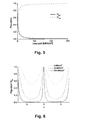
- Fig. 6 The special shape of the curves in Fig. 6 Of course, this depends mainly on the properties of the selected fluorophore or sample 10. The above example is based on a fluorescence lifetime of 2 ns. More efficient saturation (and thus lower intensities) can be achieved when dyes with longer lifetimes are used.
- Fig. 7 corresponds to Fig. 6 , where a lifetime of 10 ns was assumed here. It can clearly be seen that a flattening of the population curve already occurs here at 20 MW / cm 2 .
- Fig. 8 shows how, under these conditions and assuming an irradiation intensity of 20 MW / cm 2, the populations of the states S 0.0 , S 1.0 and T 1.0 (cf. Fig.
- the fluorescence of molecules in the overlap region of two laser radiation fields can be specifically detected by applying a lock-in detection with the sum or difference frequency f s + f c or f s -f c (the designation central field and side field meet here may no longer be allowed).
- f s + f c or f s -f c the designation central field and side field meet here may no longer be allowed.
- f s + f c or f s -f c the designation central field and side field meet here may no longer be allowed.
Landscapes
- Physics & Mathematics (AREA)
- General Physics & Mathematics (AREA)
- Chemical & Material Sciences (AREA)
- Analytical Chemistry (AREA)
- Health & Medical Sciences (AREA)
- Optics & Photonics (AREA)
- General Health & Medical Sciences (AREA)
- Nuclear Medicine, Radiotherapy & Molecular Imaging (AREA)
- Biochemistry (AREA)
- Immunology (AREA)
- Pathology (AREA)
- Engineering & Computer Science (AREA)
- Computer Vision & Pattern Recognition (AREA)
- General Engineering & Computer Science (AREA)
- Life Sciences & Earth Sciences (AREA)
- Investigating, Analyzing Materials By Fluorescence Or Luminescence (AREA)
- Microscoopes, Condenser (AREA)
Abstract
Description
Die Erfindung bezieht sich auf die auflösungsgesteigerte Lumineszenzmikroskopie und insbesondere auf ein Verfahren, bei dem eine zu untersuchende lumineszierende Probe mit Anregungsstrahlung beleuchtet wird und ein Bild der zur Lumineszenz angeregten Probe gewonnen wird. Die Erfindung bezieht sich weiter auf ein Mikroskop zur auflösungsgesteigerten Lumineszenzmikroskopie einer Probe, das Mittel zur Anregung von Lumineszenz, die in der Probe Anregungsstrahlung einstrahlen, und Mittel zur Gewinnung eines Bildes der angeregten Probe aufweist.The invention relates to the resolution-enhanced luminescence microscopy and more particularly to a method in which a luminescent sample to be examined is illuminated with excitation radiation and an image of the sample excited for luminescence is obtained. The invention further relates to a microscope for resolution-enhanced luminescence microscopy of a sample comprising means for exciting luminescence which excite excitation radiation in the sample and means for obtaining an image of the excited sample.
Ein klassisches Anwendungsgebiet der Lichtmikroskopie zur Untersuchung von biologischen Präparaten ist die Lumineszenzmikroskopie. Hierbei werden bestimmte Farbstoffe (sogenannte Phosphore oder Fluorophore) zur spezifischen Markierung von Proben, z.B. von Zellteilen, verwendet. Die Probe wird, wie erwähnt, mit Anregungsstrahlung beleuchtet und das dadurch angeregte Lumineszenzlicht mit geeigneten Detektoren erfaßt. Üblicherweise ist dazu im Lichtmikroskop ein dichroitischer Strahlteiler in Kombination mit Blockfiltern vorgesehen, die die Fluoreszenzstrahlung von der Anregungsstrahlung abspalten und eine getrennte Beobachtung ermöglichen. Durch dieses Vorgehen ist die Darstellung einzelner, verschieden gefärbter Zellteile im Lichtmikroskop möglich. Natürlich können auch mehrere Teile eines Präparates gleichzeitig mit verschiedenen, sich spezifisch an unterschiedliche Strukturen des Präparates anlagemden Farbstoffen eingefärbt werden. Dieses Verfahren bezeichnet man als Mehrfachlumineszenz. Auch kann man Proben vermessen, die per se, also ohne Farbstoffzugabe lumineszieren.A classical field of application of light microscopy for the investigation of biological preparations is luminescence microscopy. Here, certain dyes (so-called phosphors or fluorophores) are used for the specific labeling of samples, e.g. of cell parts, used. As mentioned, the sample is illuminated with excitation radiation and the luminescence light stimulated thereby is detected with suitable detectors. Typically, a dichroic beam splitter in combination with block filters is provided for this purpose in the light microscope, which split off the fluorescence radiation from the excitation radiation and enable separate observation. By this procedure, the representation of individual, differently colored cell parts in the light microscope is possible. Of course, several parts of a preparation can be dyed at the same time with different dyes that are specifically attached to different structures of the preparation. This process is called multiple luminescence. It is also possible to measure samples which luminesce per se, ie without the addition of dye.
Lumineszenz wird hier, wie allgemein üblich, als Oberbegriff für Phosphoreszenz und Fluoreszenz verstanden, erfaßt also beide Prozesse.Luminescence is understood here, as is common practice, as a generic term for phosphorescence and fluorescence, so it covers both processes.
Weiter ist es zur Probenuntersuchung bekannt, Laser-Scanning-Mikroskope (auch LSM abgekürzt) zu verwenden, die aus einem dreidimensional ausgeleuchteten Bild mittels einer konfokalen Detektionsanordnung (dann spricht man von einem konfokalen LSM) oder einer nichtlinearen Probenwechselwirkung (sogenannte Multiphotonenmikroskopie) nur diejenige Ebene wiedergeben, die sich in der Fokusebene des Objektives befindet. Es wird ein optischer Schnitt gewonnen, und die Aufzeichnung mehrerer optischer Schnitte in verschiedenen Tiefen der Probe erlaubt es anschließend, mit Hilfe eines geeigneten Datenverarbeitungsgerätes ein dreidimensionales Bild der Probe zu generieren, das aus den verschiedenen optischen Schnitten zusammengesetzt ist. Die Laser-Scanning-Mikroskopie ist somit zur Untersuchung von dicken Präparaten geeignet.Furthermore, it is known for sample examination to use laser scanning microscopes (also abbreviated LSM), which consists of a three-dimensionally illuminated image by means of a confocal detection arrangement (this is called a confocal LSM) or a nonlinear sample interaction (so-called multiphoton microscopy) only reproduce that plane which is in the focal plane of the lens. An optical section is obtained, and the recording of several optical sections at different depths of the sample then makes it possible, with the aid of a suitable data processing device, to generate a three-dimensional image of the sample, which is composed of the various optical sections. Laser scanning microscopy is thus suitable for the examination of thick specimens.
Natürlich wird auch eine Kombination von Lumineszenzmikroskopie und Laser-Scanning-Mikroskopie verwendet, bei der eine lumineszierende Probe in verschiedenen Tiefenebenen mit Hilfe eines LSM abgebildet wird.Of course, a combination of luminescence microscopy and laser scanning microscopy is also used, in which a luminescent sample is imaged at different depth levels by means of an LSM.
Prinzipiell ist die optische Auflösung eines Lichtmikroskopes, auch eines LSM, durch die physikalischen Gesetze beugungsbegrenzt. Zur optimalen Auflösung innerhalb dieser Grenzen sind spezielle Beleuchtungskonfigurationen bekannt, wie beispielsweise 4Pi-Anordnung oder Anordnungen mit Stehwellenfeldern. Damit kann die Auflösung, insbesondere in axialer Richtung gegenüber einem klassischen LSM deutlich verbessert werden. Mit Hilfe nicht-linearer Entvölkerungsprozesse kann weiter die Auflösung auf einen Faktor von bis zu 10 gegenüber einem beugungsbegrenzten konfokalen LSM angehoben werden.In principle, the optical resolution of a light microscope, including an LSM, diffraction-limited by the laws of physics. For optimal resolution within these limits, special lighting configurations are known, such as 4Pi or standing wave field devices. Thus, the resolution, especially in the axial direction compared to a classic LSM can be significantly improved. With the aid of non-linear depopulation processes, the resolution can be further increased to a factor of up to 10 compared to a diffraction-limited confocal LSM.
In den letzten Jahren ist eine Vielzahl solcher Techniken vorgeschlagen bzw. entwickelt worden, die es erlauben, optische Mikroskopie, insbesondere mit LSM, mit einer Auflösung jenseits der klassischen Abbé'schen Beugungsgrenze zu betreiben [vgl.
Um bei konventioneller Fluoreszenzmikroskopie mit gegebener numerischer Apertur (NA) und Anregungswellenlänge die Abbé-Grenze der übertragbaren Raumfrequenzen signifikant zu überschreiten, muß der erwähnte nichtlineare Zusammenhang zwischen der Intensität des anregenden und der des emittierten Lichts hergestellt werden [vgl.
Die
Die
Andere Ansätze sind die von Hell et al. vorgeschlagenen Methoden des "Ground-State-Depletion" (GSD) [vgl.
Die
Der Erfindung liegt deshalb die Aufgabe zugrunde, ein Lumineszenzmikroskopieverfahren bzw. ein Lumineszenzmikroskop anzugeben, das eine Auflösungssteigerung ohne Rückgriff auf mehrere Wellenlängen bzw. ohne aufwendige rechnerische Nachbearbeitung der Daten erreicht.The invention is therefore based on the object of specifying a luminescence microscopy method or a luminescence microscope which achieves an increase in resolution without resorting to a plurality of wavelengths or without costly computational post-processing of the data.
Diese Aufgabe wird erfindungsgemäß gelöst mit einem auflösungsgesteigerten Lumineszenz-Mikroskopieverfahren nach Anspruch 1, bei dem eine Probe durch Einstrahlung von Anregungsstrahlung zur Emission von Lumineszenzstrahlung angeregt wird und ein Bild der lumineszierenden Probe gewonnen wird, wobei in einem ersten Probenteilvolumen der Probe ein erstes Laserstrahlungsfeld der Anregungsstrahlung und in einem zweiten Probenteilvolumen der Probe ein zweites Laserstrahlungsfeld der Anregungsstrahlung eingestrahlt wird, wobei erstes und zweites Probenteilvolumen sich teilweise, aber nicht vollständig überlappen, nur das erste Laserstrahlungsfeld mit einer ersten Frequenz moduliert wird, Lumineszenzstrahlung aus dem ersten Probenteilvolumen modulationsfilternd detektiert wird, so daß Lumineszenzstrahlung aus dem zweiten Probenteilvolumen unterdrückt wird.This object is achieved according to the invention with a resolution-enhanced luminescence microscopy method according to
Die Aufgabe wird weitergelöst durch ein auflösungsgesteigertes Lumineszenzmikroskop nach Anspruch 8 mit Mitteln zum Einstrahlen von Anregungsstrahlung auf eine Probe zur Anregung der Emission von Lumineszenzstrahlung und Mittel zur Bildgewinnung der lumineszierenden Probe, wobei die Mittel zum Einstrahlen der Anregungsstrahlung Mittel zum Einstrahlen eines ersten Laserstrahlungsfelds in ein erstes Probenteilvolumen der Probe und Mittel zum Einstrahlen eines zweiten Laserstrahlungsfelds in ein zweites Probenteilvolumen der Probe aufweisen, wobei erstes und zweites Probenteilvolumen sich teilweise, aber nicht vollständig überlappen, die Mittel zum Einstrahlen des ersten Laserstrahlungsfeldes einen Modulator aufweisen, der das erste Laserstrahlungsfeld mit einer ersten Frequenz moduliert, die Mittel zur Bildgewinnung Lumineszenzstrahlung aus dem ersten Probenteilvolumen modulationsfilternd detektieren, so daß Lumineszenzstrahlung aus dem zweiten Probenteilvolumen durch die Filterung unterdrückt ist.The object is further achieved by a resolution-enhanced luminescence microscope according to
Das erfindungsgemäße Verfahren nach Anspruch 1 sowie die entsprechende Vorrichtung nach Anspruch 8 sind wie GSD oder STED den "Single-Point"-Techniken zuzuordnen, bei denen durch nichtlineare Zusammenwirkung mindestens zweier Laserstrahlungsfeldern eine Auflösungssteigerung über die Auflösung der Laserstrahlungsfeldeinstrahlung hinaus vollzogen wird. Als nichtlinearer Prozess kann ähnlich wie bei
Erfindungsgemäß werden also zwei Laserstrahlungsfelder zur Auflösungssteigerung eingestrahlt. Einer der beiden Laserstrahlungsfelder wird moduliert. Dieses Laserstrahlungsfeld wird nachfolgend als Zentralstrahl bzw. Zentralstrahlung oder Zentrallaserstrahlung bezeichnet. Dieses Laserstrahlungsfeld überlappend aber nicht vollständig überdeckend wird ein zweites Laserstrahlungsfeld eingestrahlt, dessen Strahlung nicht linear moduliert ist. Dieses Laserstrahlungsfeld wird hier nachfolgend als Seitenlaserstrahlung oder Seitenlaserstrahl angesprochen. Vorzugsweise werden die beiden Laserstrahlungsfelder so strukturiert, daß das Maximum des Zentrallaserstrahls mit dem Interferenzminimum des Seitenlaserstrahls zusammenfällt. Prinzipiell ist die Auflösung gegenüber der Auflösung, mit der Zentrallaserstrahl sowie Seitenlaserstrahl eingekoppelt werden, verbessert.Thus, according to the invention, two laser radiation fields are irradiated to increase the resolution. One of the two laser radiation fields is modulated. This laser radiation field is referred to below as central beam or central radiation or central laser radiation. This laser radiation field overlapping but not completely overlapping a second laser radiation field is irradiated, the radiation is not modulated linearly. This laser radiation field is addressed here below as a side laser radiation or side laser beam. Preferably, the two laser radiation fields are structured so that the maximum of the central laser beam coincides with the interference minimum of the side laser beam. In principle, the resolution is improved compared to the resolution with which central laser beam and side laser beam are coupled in.
Der erfindungsgemäße Ansatz ist eine Weiterentwicklung der bekannten GSD- und STED-Verfahren. Er hat gegenüber diesen allerdings einige Vorteile, die hier kurz erwähnt seien sollen:
- GSD basiert auf einer Sättigung der Triplettbesetzung und erfordert daher Moleküle mit großer Intersystem-Crossing-Rate. Diese Einschränkung ist bei der modulationsmarkierten Fluoreszenz nicht gegeben, denn sowohl die Seitenlaserstrahl-T1,0-Anregung als auch die Seitenlaserstrahl-S1,0-Anregung wirken sich nicht auf das durch den Zentrallaserstrahl generierte Signal aus. In dem zuerst genannten Fall ergibt sich keine Fluorezenz, während in dem zuletzt genannten Fall keine modulierte Fluoreszenz auftritt.
- Ein Nachteil des GSD-Verfahrens ist die relativ lange Pixel-Verweildauer beim Abscannen, das zur Bilderzeugung nötig ist. Zum einen wird sie benötigt, um das für die Triplettsättigung nötige stationäre Gleichgewicht zu erreichen (ca. 10 µs). Weiter ist nach der Detektion eines Punktes zur Detektion eines benachbarten Punktes zunächst eine Relaxation aller Moleküle zurück in den Grundzustand erforderlich (nochmals ca. 10 µs). Erfindungsgemäß ist eine Sättigung des Triplettzustands nicht erforderlich, weshalb nun mit kürzeren Verweildauern gearbeitet werden kann, die nach unten im Wesentlichen durch die Periode der Zentrallaserstrahlmodulationen limitiert sind.
- Die im Rahmen der Erfindung benötigten Intensitäten fallen niedriger als bei STED aus.
- Ein wesentlicher Vorteil der Erfindung ist die Flexibilität hinsichtlich der Wahl des Farbstoffs sein. Während man bei GSD durch das nötige Intersystern-Crossing eingeschränkt ist, werden bei STED Moleküle benötigt, bei denen eine möglichst effiziente Abregung des S1,0-Zustands möglich ist. Die Erfindung ist demgegenüber mit fast jedem Farbstoff möglich, dessen Niveauschema dem in
Fig. 1 skizzierten ungefähr entspricht. Eine Optimierung der Reaktionsraten (z.B. hinsichtlich moderat längerer Fluoreszenzlebensdauern) ist vorteilhaft, stellt aber keine prinzipielle Beschränkung des Verfahrens dar. Es ist zu betonen, daß die wesentliche Modifikation hinsichtlich konventioneller Techniken in der Art der Anregung und Detektion zu suchen sind und weniger in der Wahl der zu untersuchenden Probe (ganz im Gegensatz beispielsweise zuDE 10325460 A1 - Bei den bisher realisierten STED-Experimenten sind zwei Wellenlängen nötig, wohingegen die Erfindung mit nur einer Wellenlänge arbeitet. Die Anwendung mehrere dichroitischer Strahlteiler ist nicht erforderlich. Somit kann ein verhältnismäßig einfacher Aufbau verwendet werden.
- Bei STED-Experimenten ist in der Regel eine Anwendung von intensiven gepulsten Lasern sinnvoll, denn die Population des angeregten Zustands sollte im Seitenlaserstrahlbereich abgebaut sein, bevor Fluoreszenz einsetzt. Demgegenüber kann die Erfindung mit cw-Lasem arbeiten, die gleichzeitig eingestrahlt werden. Vorteilhaft ist es allerdings, die Bestrahlung mit dem Zentrallaserstrahl gegenüber dem Seitenlaserstrahl um ca. 10 ns zu verzögern, da dann bereits eine weitgehende Depopulation des Grundzustands stattgefunden hat (vgl.
Fig. 7 ). Unter Umständen ist es auch möglich die Modulation in Form eines gepulsten Lasers zu realisieren.
- GSD is based on saturation of triplet occupancy and therefore requires molecules with large intersystem crossing rates. This limitation is not present in modulation-labeled fluorescence because both the side laser beam T 1.0 excitation and the side laser beam S 1.0 excitation do not affect the signal generated by the center laser beam. In the former case, there is no fluorescence, whereas in the latter case no modulated fluorescence occurs.
- A disadvantage of the GSD method is the relatively long pixel dwell time during scanning, which is necessary for image generation. On the one hand, it is needed to reach the stationary equilibrium necessary for triplet saturation (about 10 μs). Furthermore, after the detection of a point for the detection of an adjacent point, first of all a relaxation of all molecules back to the ground state is required (again about 10 μs). According to the invention, a saturation of the triplet state is not required, which is why it is now possible to work with shorter residence times, which are limited to the bottom essentially by the period of the central laser beam modulations.
- The intensities required in the context of the invention are lower than in STED.
- A significant advantage of the invention is its flexibility in the choice of dye . While GSD is constrained by the necessary intersystern crossing, STED requires molecules that allow the most efficient excitation of the S 1.0 state. In contrast, the invention is possible with almost any dye whose level scheme corresponds to that in
Fig. 1 sketched roughly corresponds. An optimization of the reaction rates (eg with regard to moderately longer fluorescence lifetimes) is advantageous, but does not represent a fundamental limitation of the process. It should be emphasized that the substantial modification with respect to conventional techniques is to be sought in the mode of excitation and detection and less in the choice the sample to be examined (in contrast, for example, toDE 10325460 A1 - In the previously realized STED experiments two wavelengths are needed, whereas the invention operates with only one wavelength . The application of multiple dichroic beam splitters is not required. Thus, a relatively simple structure can be used.
- In STED experiments, it is usually useful to use intense pulsed lasers because the population of the excited state should be degraded in the side laser beam region before fluorescence sets in. In contrast, the invention can work with cw Lasem, which are irradiated simultaneously. It is advantageous, however, to delay the irradiation with the central laser beam with respect to the side laser beam by about 10 ns, because then already a substantial depopulation of the ground state has taken place (see.
Fig. 7 ). Under certain circumstances it is also possible to realize the modulation in the form of a pulsed laser.
Die erfindungsgemäße modulationsmarkierte Fluoreszenz (MMF) erlaubt eine hochauflösende optische Abbildungen nochmals zu verbessern. Sie ist eine Alternativen zu den beiden bereits bekannten "Single-Point"-Verfahren GSD und STED. Wie dort wird auch hier mit mindestens zwei Laserstrahlungsfeldern (Zentral- und Seitenlaserstrahl) gearbeitet. Während man bei GSD bzw. STED allerdings bemüht ist, die Fluoreszenz im Seitenlaserstrahlbereich komplett zu unterdrücken, wird bei MMF der Zentral- und der seitlich angeregte Probenbereich beispielsweise durch modulierte Zentrallaserstrahlanregung mit anschließender phasensensitiver Detektion vom interessierenden Signal unterscheidbar und damit separierbar. Die Anwendung einer modulationsfrequenzempfindlichen Detektion, z.B. durch Lock-In-Technik, ist ein zentraler Punkt dafür. Das Vermeiden von markierter Fluoreszenz im Seitenlaserstrahlbereich, d.h. eine Anregung durch Photonen des ZentralLaserstrahlungsfeldes, läßt sich durch ein unausgeglichenes Intensitätsverhältnis zwischen den Laserstrahlungsfeldern bzw. eine gesättigte Depopulation des Grundzustands erreichen. Ein wesentlicher Vorteil von MMF gegenüber den bekannten Verfahren GSD bzw. STED ist die Freiheit in der Wahl des Fluorophors und die Möglichkeit, Zentral- und Seitenlaser bei der gleichen Wellenlänge betreiben zu können.The modulation-labeled fluorescence (MMF) according to the invention makes it possible to further improve high-resolution optical imaging. It is an alternative to the two already known "single-point" methods GSD and STED. Like here, at least two laser radiation fields (central and side laser beam) are also used. While efforts are being made in GSD or STED to completely suppress the fluorescence in the side laser beam range, in MMF the central and the laterally excited sample region can be distinguished from the signal of interest by modulated central laser beam excitation with subsequent phase-sensitive detection and thus be separated. The application of modulation frequency sensitive detection, e.g. Lock-in technology is central to this. The avoidance of labeled fluorescence in the side laser beam region, i. An excitation by photons of the central laser radiation field can be achieved by an unbalanced intensity ratio between the laser radiation fields or a saturated depopulation of the ground state. A major advantage of MMF compared to the known methods GSD or STED is the freedom in the choice of fluorophore and the ability to operate central and side lasers at the same wavelength can.
Die Erfindung wird nachfolgend unter Bezugnahme auf die Zeichnungen beispielshalber noch näher erläutert. In den Zeichnungen zeigt:
- Fig. 1
- ein beispielhaftes Energieschema eines Farbstoffmoleküls oder einer Probe, das bzw. die im Rahmen der Erfindung verwendet wird;
- Fig. 2
- eine mögliche Intensitätsverteilung für einen Seitenstrahl und einen Zentralstrahl im erfindungsgemäßen Verfahren bzw. in der erfindungsgemäßen Vorrichtung;
- Fig. 3
- ein exemplarisches Schema für eine Vorrichtung gemäß der Erfindung;
- Fig. 4
- das Intensitätsverhältnis zwischen Zentralstrahl und Seitenstrahl für verschiedene Ausführungsformen der Erfindung;
- Fig. 5
- die Gleichgewichtspopulation als Funktion der eingestrahlten Laserstrahlungsintensität für einen beispielhaften Farbstoff, er im Rahmen der Erfindung verwendet werden kann;
- Fig. 6
- die Gleichgewichtspopulation des Grundzustandes entlang einer normalisierten Koordinate bei Einstrahlung des Seitenlaserstrahls im erfindungsgemäßen Verfahren für drei verschiedene mögliche Spitzenintensitäten;
- Fig. 7
- eine Abbildung ähnlich der
Fig. 6 für andere Farbstoffparameter und - Fig. 8
- Population der Grundzustände sowie angeregter Zustände als Funktion der Beleuchtungszeit bei einer bestimmten Ausführungsform der Erfindung.
- Fig. 1
- an exemplary energy scheme of a dye molecule or sample used in the invention;
- Fig. 2
- a possible intensity distribution for a side beam and a central beam in the method according to the invention or in the device according to the invention;
- Fig. 3
- an exemplary scheme for a device according to the invention;
- Fig. 4
- the intensity ratio between central beam and side beam for various embodiments of the invention;
- Fig. 5
- the equilibrium population as a function of irradiated laser radiation intensity for an exemplary dye, it can be used in the invention;
- Fig. 6
- the equilibrium population of the ground state along a normalized coordinate when the side laser beam is irradiated in the method according to the invention for three different possible peak intensities;
- Fig. 7
- a picture similar to the one
Fig. 6 for other dye parameters and - Fig. 8
- Population of the ground states and excited states as a function of the illumination time in a specific embodiment of the invention.
Die Anregung erfolgt erfindungsgemäß nun durch mindestens zwei unterschiedliche Lichtfelder, die in gleicher Weise angeordnet sind wie Anregungs- und SättigungsLaserstrahlungsfeld im bekannten GSD- bzw. STED-Verfahren. Die Verwendung von Lasern erscheint sinnvoll, stellt aber generell keine Beschränkung des Verfahrens dar.According to the invention, the excitation now takes place by means of at least two different light fields, which are arranged in the same way as the excitation and saturation laser radiation field in the known GSD or STED method. The use of lasers seems reasonable, but generally does not limit the process.
Für den nicht räumlich strahlgeformten Zentralstrahlengang 4 ist eine Modulationseinheit 6 vorgesehen, die diesen Strahl mit einer Frequenz fc moduliert. Nach Überlagerung werden beide Strahlen beugungsbegrenzt in die Probe 10 fokussiert. Dazu dient ein Objektiv 9. Der Fokus wird zusätzlich zweidimensional mittels einer Scan-Einheit 8 verschoben.For the non-spatially beam-shaped
In der Probe 10 entsteht folglich an verschiedenen Stellen die in
Wesentlich ist nun, daß das so gemessene Fluoreszenzsignal durch Berücksichtigung der Modulation dem jeweiligen Strahl 3, 4 zugeordnet werden kann, d.h. die Fluoreszenz wird entsprechend markiert. Dies gelingt durch Ausnutzung von Modulationseffekten. Im einfachsten Fall ist beispielsweise der Seitenstrahl nicht moduliert (fs = 0), während die Intensität des Zentralstrahls sinusförmig mit einer Frequenz fc von typischerweise 1-100 MHz variiert, wozu im Zentralstrahlengang die entsprechende Modulationseinheit 6 eingebracht ist. Das durch den Zentralstrahl erzeugte Fluoreszenzsignal ist dann ebenfalls mit der Frequenz fc moduliert. Dieser Effekt entspricht unter anderem demjenigen, welcher auch bei der Phasenmethode zur Messung von Fluoreszenzlebensdauern angewandt wird (siehe z.B.
Die Modulationsfrequenz fc kann dem Farbstoff entsprechend optimiert werden. Wird nun wie in
Bei einer Anordnung entsprechend
Die genannte Bedingung läßt sich beispielsweise erfüllen, wenn der Seitenlaserstrahl 5 eine so hohe Intensität aufweist, daß in der Probe 10 eine Sättigung des Fluoreszenzübergangs eintritt. Liegt gemäß 
wobei Np,s den Photonenfluss (des Seitenlaserstrahls 5) und σ den Absorptionsquerschnitt des optischen Übergangs darstellen. Die Intensität der Fluoreszenzstrahlung ist proportional zu N1,v, woran sich direkt der oben für hohe Auflösung nötige nichtlineare Zusammenhang zwischen der Intensität des anregenden und der des emittierten Lichts verifizieren läßt. Für sehr hohe Photonenflüsse wird eine Gleichbesetzung der Zustände und damit eine Sättigung erreicht. Zudem ergibt sich für den Fall einer im Vergleich zum Seitenlaserstrahls 5 sehr viel kleineren Intensität des modulierten Zentrallaserstrahls 4 (d.h. Np,s >> Np,c), daß die Wahrscheinlichkeit einer Fluoreszenzanregung durch den Zentrallaserstrahl 4 nur am Intereferenzminimum wesentlich von Null verschieden ist. Dieser Sachverhalt wird anhand von
where N p, s represent the photon flux (of the side laser beam 5) and σ the absorption cross section of the optical transition. The intensity of the fluorescence radiation is proportional to N 1, v , which can directly verify the nonlinear relationship between the intensity of the stimulating light and that of the emitted light necessary for high resolution. For very high photon fluxes a uniform occupation of the states and thus a saturation is achieved. In addition, in the case of an intensity of the modulated
In einer Weiterbildung werden die in
Die spezielle Form der Kurven in
In einem realen System ist die Bedingung eines verschwindenden Intersystem-Crossings in der Regel nicht vollständig erfüllt. Als typische Werte können in diesem Zusammenhang Raten von kISC = (10-6s)-1 und kPh = (2*10-6s)-1 angenommen werden, wie sie beispielsweise für Rhodamin 6G dokumentiert sind [vgl.
An dieser Stelle sei erwähnt, daß auch andere Laserstrahlungsfeldanordnungen und Modulationsschemata als das oben beschriebene denkbar sind. So kann beispielsweise gezielt die Fluoreszenz von Molekülen im Überlappbereich zweier Laserstrahlungsfelder detektiert werden, indem eine Lock-In-Detektion mit der Summen- oder Differenzfrequenz fs+fc bzw. fs-fc angewandt wird (die Bezeichnung Zentralfeld und Seitenfeld trifft hier unter Umständen nicht mehr zu). Werden dabei zwei einfache (teilweise überlappende) Airy-Profile gewählt, so ist eine ähnliche Auflösung erreichbar, wie beim sogen. "Point-Spread-Autocorrelation-Function-Imaging" [vgl.
Claims (14)
- A method for resolution-enhanced luminescence microscopy in which method- a sample (10) is excited through irradiation of excitation radiation (4, 5) to the emission of luminescence radiation, and an image of the luminescing sample (10) is aquired, wherein- a first laser radiation field (5) of the excitation radiation is irradiated to a first volume part of the sample (10), and a second laser radiation field (4) of the excitation radiation is irradiated to a second volume part of the sample, wherein- the first volume part of the sample and the second volume part of the sample overlap one another partially but not completely, characterized in that- only the first laser radiation field (5) is modulated with a first frequency,- the first and second laser radiation fields (4, 5) have the same wavelength and- luminescence radiation is detected from the first volume part of the sample with modulation filtering so that luminescence radiation from the second volume part of the sample is suppressed.
- The method according to claim 1, wherein the second volume part of the sample is brought to luminescence saturation by the second laser radiation field (4).
- The method according to any of the above claims, wherein the intensity of the second laser radiation field (4) is at least 50-times greater, preferably 100-times greater, than that of the first laser radiation field (5).
- The method according to any of the above claims, wherein at least the first laser radiation field (5) is focused on the sample (10) in a diffraction-limited manner.
- The method according to any of the above claims, wherein the second laser radiation field (4) is modulated with a second frequency that differs from the first frequency.
- The method according to any of the above claims, wherein modulation-filtering detection is carried out by lock-in technique.
- The method according to any of the above claims, wherein the first frequency is between 1 MHz and 100 MHz.
- A resolution-enhanced luminescence microscope comprising means for irradiating a sample (10) with excitation radiation for exciting the emission of luminescence radiation, and means for acquiring an image of the luminescing sample (10), wherein the means for irradiating with excitation radiation comprise a modulator (6) modulating the excitation radiation with a first frequency, wherein- the means for irradiating with excitation radiation have means for irradiating a first volume part of the sample (10) with a first laser radiation field (5) and means for irradiating a second volume part of the sample with a second laser radiation field (4),- the first volume part of the sample and the second volume part of the sample overlap one another partially but not completely, characterized in that- the first and second laser radiation fields (4, 5) have the same wavelength and- the modulator (6) modulates only the first laser radiation field (5) with the first frequency, and- the means for acquiring an image detect luminescence radiation from the first volume part of the sample with modulation filtering so that the luminescence radiation from the second volume part of the sample is suppressed by the filtering.
- The microscope according to claim 8, wherein the second volume part of the sample is brought to luminescence saturation by the means for irradiating with second laser radiation field (4).
- The microscope according to any of the above device claims, wherein the intensity of the second laser radiation field (4) is at least 50-times, preferably 100-times greater, than that of the first laser radiation field (5).
- The microscope according to any of the above device claims, further comprising optics (9) which focus the laser radiation for the first laser radiation field (5) on the sample (10) in a diffraction-limited manner.
- The microscope according to according to any of the above device claims, wherein a modulator is provided which modulates the second laser radiation field (4) with a second frequency that differs from the first frequency.
- The microscope according to any of the above device claims, wherein the means for acquiring images have a lock-in amplifier (13), the first frequency and the signals of a detector (12) being fed to the lock-in amplifier (13).
- The microscope according to any of the above device claims, wherein the first frequency is between 1 MHz and 100 MHz.
Applications Claiming Priority (2)
| Application Number | Priority Date | Filing Date | Title |
|---|---|---|---|
| DE102006046369A DE102006046369A1 (en) | 2006-09-29 | 2006-09-29 | Luminescence microscopy method for examining biological preparations, involves detecting luminescence radiation from sample partial volume in modulation-filtering manner, so that luminescence radiation from another volume is suppressed |
| PCT/EP2007/007882 WO2008040435A1 (en) | 2006-09-29 | 2007-09-10 | Luminescence microscopy with enhanced resolution |
Publications (2)
| Publication Number | Publication Date |
|---|---|
| EP2067020A1 EP2067020A1 (en) | 2009-06-10 |
| EP2067020B1 true EP2067020B1 (en) | 2012-05-30 |
Family
ID=38924834
Family Applications (1)
| Application Number | Title | Priority Date | Filing Date |
|---|---|---|---|
| EP07802252A Active EP2067020B1 (en) | 2006-09-29 | 2007-09-10 | Luminescence microscopy with enhanced resolution |
Country Status (5)
| Country | Link |
|---|---|
| US (2) | US20090294694A1 (en) |
| EP (1) | EP2067020B1 (en) |
| JP (1) | JP2010505094A (en) |
| DE (1) | DE102006046369A1 (en) |
| WO (1) | WO2008040435A1 (en) |
Families Citing this family (24)
| Publication number | Priority date | Publication date | Assignee | Title |
|---|---|---|---|---|
| JP5699421B2 (en) * | 2008-09-16 | 2015-04-08 | 横河電機株式会社 | Microscope equipment |
| DE102008054317A1 (en) | 2008-11-03 | 2010-05-06 | Carl Zeiss Microlmaging Gmbh | combining microscopy |
| JP5589374B2 (en) * | 2009-06-22 | 2014-09-17 | 横河電機株式会社 | Microscope equipment |
| DE102010028138A1 (en) * | 2010-04-22 | 2011-10-27 | MAX-PLANCK-Gesellschaft zur Förderung der Wissenschaften e.V. | Determining the distribution of a substance by scanning with a measuring front |
| JP6003072B2 (en) * | 2011-02-08 | 2016-10-05 | 横河電機株式会社 | Microscope equipment |
| JP5609729B2 (en) * | 2011-03-18 | 2014-10-22 | 横河電機株式会社 | Microscope device, observation method and sample mounting mechanism |
| JP5784393B2 (en) * | 2011-07-11 | 2015-09-24 | オリンパス株式会社 | Sample observation equipment |
| US9664614B2 (en) | 2011-07-11 | 2017-05-30 | University Of Limerick | Method for high resolution sum-frequency generation and infrared microscopy |
| DE102012017922B4 (en) * | 2012-09-11 | 2024-03-14 | Carl Zeiss Microscopy Gmbh | Optical arrangement and light microscope |
| ITTO20120929A1 (en) * | 2012-10-23 | 2014-04-24 | Fond Istituto Italiano Di Tecnologia | OPTICAL MICROSCOPY SYSTEM BASED ON REVERSIBLE SATURABLE OPTICAL TRANSITIONS (RESOLFT), IN FREQUENCY MODULATION. |
| EP2941662B1 (en) | 2013-01-04 | 2019-03-13 | University of Limerick | Differential infra red nanoscopy system and method |
| DE102013100174A1 (en) | 2013-01-09 | 2014-07-10 | MAX-PLANCK-Gesellschaft zur Förderung der Wissenschaften e.V. | A method for spatially high resolution imaging of a luminophor structure of a sample |
| DE102013100172A1 (en) * | 2013-01-09 | 2014-07-10 | MAX-PLANCK-Gesellschaft zur Förderung der Wissenschaften e.V. | A method for spatially high resolution imaging of a luminophor structure of a sample |
| JP6253266B2 (en) * | 2013-06-11 | 2017-12-27 | オリンパス株式会社 | Confocal image generator |
| KR20160042434A (en) | 2013-08-08 | 2016-04-19 | 어플라이드 머티어리얼스, 인코포레이티드 | Photonic activation of reactants for sub-micron feature formation using depleted beams |
| JP6613552B2 (en) * | 2013-09-09 | 2019-12-04 | 株式会社ニコン | Super-resolution observation apparatus and super-resolution observation method |
| JP2016012114A (en) * | 2014-06-02 | 2016-01-21 | オリンパス株式会社 | Luminaire, microscope device having the same, and microscope observation method |
| US9384537B2 (en) * | 2014-08-31 | 2016-07-05 | National Taiwan University | Virtual spatial overlap modulation microscopy for resolution improvement |
| DE102016117096C5 (en) * | 2015-09-22 | 2023-11-30 | MAX-PLANCK-Gesellschaft zur Förderung der Wissenschaften e.V. | Method for high-resolution local imaging of a structure in a sample |
| EP3159676B1 (en) * | 2015-10-23 | 2018-04-04 | Abberior Instruments GmbH | Method and device for high precision imaging of a structure of a sample marked with fluorescence markers |
| US11181727B2 (en) * | 2016-03-10 | 2021-11-23 | University Of Notre Dame Du Lac | Super-sensitivity multiphoton frequency-domain fluorescence lifetime imaging microscopy |
| WO2018083772A1 (en) * | 2016-11-02 | 2018-05-11 | 株式会社ニコン | Microscope system |
| IT201700118432A1 (en) | 2017-10-19 | 2019-04-19 | Fondazione St Italiano Tecnologia | COLLECTED MICROSCOPY METHOD BY MEANS OF HIGH SPATIAL STIMULATED EMISSION |
| KR102105814B1 (en) * | 2018-12-21 | 2020-05-04 | 한국표준과학연구원 | Laser Spatial Modulation Super-resolution Optical Microscopy |
Family Cites Families (15)
| Publication number | Priority date | Publication date | Assignee | Title |
|---|---|---|---|---|
| DE4331570C2 (en) * | 1993-08-17 | 1996-10-24 | Hell Stefan | Process for the optical excitation of a sample |
| US6903347B2 (en) * | 1994-07-15 | 2005-06-07 | Stephen C. Baer | Superresolution in microlithography and fluorescence microscopy |
| US5866911A (en) * | 1994-07-15 | 1999-02-02 | Baer; Stephen C. | Method and apparatus for improving resolution in scanned optical system |
| US5814820A (en) * | 1996-02-09 | 1998-09-29 | The Board Of Trustees Of The University Of Illinois | Pump probe cross correlation fluorescence frequency domain microscope and microscopy |
| US5978074A (en) * | 1997-07-03 | 1999-11-02 | Therma-Wave, Inc. | Apparatus for evaluating metalized layers on semiconductors |
| DE19956620A1 (en) * | 1999-11-25 | 2001-05-31 | Zeiss Carl Jena Gmbh | Detecting fluorescence events in microscope, involves exposing specimen to light from modulated and/or pulsed laser source, detecting fluorescence at two or more detector phase angles |
| US6844963B2 (en) * | 2000-03-23 | 2005-01-18 | Olympus Optical Co., Ltd. | Double-resonance-absorption microscope |
| DE10063276C2 (en) * | 2000-12-19 | 2002-11-07 | Leica Microsystems | scanning microscope |
| DE10154699B4 (en) * | 2001-11-09 | 2004-04-08 | MAX-PLANCK-Gesellschaft zur Förderung der Wissenschaften e.V. | Method and device for stimulating an optical transition in a spatially limited manner |
| DE10231543B3 (en) * | 2002-07-11 | 2004-02-26 | Universität Siegen | Confocal 3D scanning absorption |
| DE10340965A1 (en) * | 2003-09-05 | 2005-03-24 | Leica Microsystems Heidelberg Gmbh | scanning microscope |
| EP1668394A1 (en) * | 2003-09-25 | 2006-06-14 | Leica Microsystems Heidelberg GmbH | Microscope with evanescent wave illumination |
| DE102004039035A1 (en) * | 2004-04-07 | 2005-10-27 | EuroPhoton GmbH Gesellschaft für optische Sensorik | Method and apparatus for fluorescence lifetime imaging nanoscopy |
| JP2006047912A (en) | 2004-08-09 | 2006-02-16 | Olympus Corp | Super-resolution microscope |
| US7485875B2 (en) * | 2005-07-22 | 2009-02-03 | Carl Zeiss Microimaging Gmbh | Resolution-enhanced luminescence microscopy |
-
2006
- 2006-09-29 DE DE102006046369A patent/DE102006046369A1/en not_active Withdrawn
-
2007
- 2007-09-10 WO PCT/EP2007/007882 patent/WO2008040435A1/en active Application Filing
- 2007-09-10 JP JP2009529561A patent/JP2010505094A/en not_active Withdrawn
- 2007-09-10 EP EP07802252A patent/EP2067020B1/en active Active
- 2007-09-10 US US12/442,093 patent/US20090294694A1/en not_active Abandoned
-
2012
- 2012-01-03 US US13/342,370 patent/US8399857B2/en active Active
Also Published As
| Publication number | Publication date |
|---|---|
| JP2010505094A (en) | 2010-02-18 |
| DE102006046369A1 (en) | 2008-04-03 |
| EP2067020A1 (en) | 2009-06-10 |
| US8399857B2 (en) | 2013-03-19 |
| US20090294694A1 (en) | 2009-12-03 |
| US20120097865A1 (en) | 2012-04-26 |
| WO2008040435A1 (en) | 2008-04-10 |
Similar Documents
| Publication | Publication Date | Title |
|---|---|---|
| EP2067020B1 (en) | Luminescence microscopy with enhanced resolution | |
| EP1907826B2 (en) | Luminescence microscopy with enhanced resolution | |
| EP3864454B1 (en) | Method and device for high-resolution fluorescence microscopy | |
| DE19829981C2 (en) | Method and arrangement for confocal microscopy | |
| DE4416558C2 (en) | Method for optically measuring a sample point of a sample and device for carrying out the method | |
| DE102011055367B4 (en) | Method and device for tracking a movement of a particle, in particular a single molecule, in a sample | |
| EP2069761B1 (en) | Method and apparatus for the highly resolved optical scanning of a sample | |
| EP2097781B1 (en) | Laser microscope with a physically separating beam splitter | |
| DE102016119263B4 (en) | A method for spatially high-resolution determination of the location of a singled, excitable light for the emission of luminescent light molecule in a sample | |
| DE102016117096B4 (en) | Method for high-resolution local imaging of a structure in a sample | |
| EP1862839B2 (en) | Microscope with improved resolution | |
| DE102016119264B4 (en) | A method for spatially high-resolution determination of the location of a singled, excitable light for the emission of luminescent light molecule in a sample | |
| WO2009100830A1 (en) | Apparatus and method for high spatial resolution imaging of a structure of a sample | |
| DE102005034443A1 (en) | Sample e.g. cell particle, luminescence microscopy method, involves prevailing one of sample regions for image of sample, so that image has local resolution which is enhanced in relation to excitation radiation distribution | |
| DE102006009831B4 (en) | Method and microscope for spatially high-resolution examination of samples | |
| EP2803977A1 (en) | Method for high resolution 3D locating microscopy | |
| DE102020134495B4 (en) | Method and microscope for recording trajectories of individual particles in a sample | |
| DE102020127320B3 (en) | Method and fluorescence microscope for localizing individual fluorescent dye molecules by adaptive scanning | |
| EP1875293B1 (en) | High-resolution optical microscopy featuring fluorescence transient measurement | |
| DE102022112384B4 (en) | METHOD, LIGHT MICROSCOPE AND COMPUTER PROGRAM FOR SETTING A TIME DELAY BETWEEN LIGHT PULSES | |
| DE102018132212B4 (en) | Method and microscope for high-resolution light microscopic imaging of a sample | |
| WO2024038190A1 (en) | Method and device for simultaneously tracking two emitters | |
| WO2020058074A1 (en) | Optical arrangement for fluorescence microscopy applications |
Legal Events
| Date | Code | Title | Description |
|---|---|---|---|
| PUAI | Public reference made under article 153(3) epc to a published international application that has entered the european phase |
Free format text: ORIGINAL CODE: 0009012 |
|
| 17P | Request for examination filed |
Effective date: 20090227 |
|
| AK | Designated contracting states |
Kind code of ref document: A1 Designated state(s): AT BE BG CH CY CZ DE DK EE ES FI FR GB GR HU IE IS IT LI LT LU LV MC MT NL PL PT RO SE SI SK TR |
|
| AX | Request for extension of the european patent |
Extension state: AL BA HR MK RS |
|
| RIN1 | Information on inventor provided before grant (corrected) |
Inventor name: LIPPERT, HELMUT |
|
| 17Q | First examination report despatched |
Effective date: 20090813 |
|
| GRAP | Despatch of communication of intention to grant a patent |
Free format text: ORIGINAL CODE: EPIDOSNIGR1 |
|
| DAX | Request for extension of the european patent (deleted) | ||
| GRAS | Grant fee paid |
Free format text: ORIGINAL CODE: EPIDOSNIGR3 |
|
| RIN1 | Information on inventor provided before grant (corrected) |
Inventor name: LIPPERT, HELMUT |
|
| GRAA | (expected) grant |
Free format text: ORIGINAL CODE: 0009210 |
|
| AK | Designated contracting states |
Kind code of ref document: B1 Designated state(s): AT BE BG CH CY CZ DE DK EE ES FI FR GB GR HU IE IS IT LI LT LU LV MC MT NL PL PT RO SE SI SK TR |
|
| REG | Reference to a national code |
Ref country code: GB Ref legal event code: FG4D Free format text: NOT ENGLISH |
|
| REG | Reference to a national code |
Ref country code: CH Ref legal event code: EP |
|
| RIN2 | Information on inventor provided after grant (corrected) |
Inventor name: LIPPERT, HELMUT |
|
| REG | Reference to a national code |
Ref country code: AT Ref legal event code: REF Ref document number: 560283 Country of ref document: AT Kind code of ref document: T Effective date: 20120615 |
|
| REG | Reference to a national code |
Ref country code: IE Ref legal event code: FG4D Free format text: LANGUAGE OF EP DOCUMENT: GERMAN |
|
| REG | Reference to a national code |
Ref country code: DE Ref legal event code: R096 Ref document number: 502007009950 Country of ref document: DE Effective date: 20120726 |
|
| REG | Reference to a national code |
Ref country code: NL Ref legal event code: VDEP Effective date: 20120530 |
|
| REG | Reference to a national code |
Ref country code: LT Ref legal event code: MG4D Effective date: 20120530 |
|
| PG25 | Lapsed in a contracting state [announced via postgrant information from national office to epo] |
Ref country code: SE Free format text: LAPSE BECAUSE OF FAILURE TO SUBMIT A TRANSLATION OF THE DESCRIPTION OR TO PAY THE FEE WITHIN THE PRESCRIBED TIME-LIMIT Effective date: 20120530 Ref country code: LT Free format text: LAPSE BECAUSE OF FAILURE TO SUBMIT A TRANSLATION OF THE DESCRIPTION OR TO PAY THE FEE WITHIN THE PRESCRIBED TIME-LIMIT Effective date: 20120530 Ref country code: FI Free format text: LAPSE BECAUSE OF FAILURE TO SUBMIT A TRANSLATION OF THE DESCRIPTION OR TO PAY THE FEE WITHIN THE PRESCRIBED TIME-LIMIT Effective date: 20120530 Ref country code: CY Free format text: LAPSE BECAUSE OF FAILURE TO SUBMIT A TRANSLATION OF THE DESCRIPTION OR TO PAY THE FEE WITHIN THE PRESCRIBED TIME-LIMIT Effective date: 20120530 Ref country code: IS Free format text: LAPSE BECAUSE OF FAILURE TO SUBMIT A TRANSLATION OF THE DESCRIPTION OR TO PAY THE FEE WITHIN THE PRESCRIBED TIME-LIMIT Effective date: 20120930 |
|
| PG25 | Lapsed in a contracting state [announced via postgrant information from national office to epo] |
Ref country code: SI Free format text: LAPSE BECAUSE OF FAILURE TO SUBMIT A TRANSLATION OF THE DESCRIPTION OR TO PAY THE FEE WITHIN THE PRESCRIBED TIME-LIMIT Effective date: 20120530 Ref country code: LV Free format text: LAPSE BECAUSE OF FAILURE TO SUBMIT A TRANSLATION OF THE DESCRIPTION OR TO PAY THE FEE WITHIN THE PRESCRIBED TIME-LIMIT Effective date: 20120530 Ref country code: GR Free format text: LAPSE BECAUSE OF FAILURE TO SUBMIT A TRANSLATION OF THE DESCRIPTION OR TO PAY THE FEE WITHIN THE PRESCRIBED TIME-LIMIT Effective date: 20120831 |
|
| PG25 | Lapsed in a contracting state [announced via postgrant information from national office to epo] |
Ref country code: DK Free format text: LAPSE BECAUSE OF FAILURE TO SUBMIT A TRANSLATION OF THE DESCRIPTION OR TO PAY THE FEE WITHIN THE PRESCRIBED TIME-LIMIT Effective date: 20120530 Ref country code: NL Free format text: LAPSE BECAUSE OF FAILURE TO SUBMIT A TRANSLATION OF THE DESCRIPTION OR TO PAY THE FEE WITHIN THE PRESCRIBED TIME-LIMIT Effective date: 20120530 Ref country code: EE Free format text: LAPSE BECAUSE OF FAILURE TO SUBMIT A TRANSLATION OF THE DESCRIPTION OR TO PAY THE FEE WITHIN THE PRESCRIBED TIME-LIMIT Effective date: 20120530 Ref country code: CZ Free format text: LAPSE BECAUSE OF FAILURE TO SUBMIT A TRANSLATION OF THE DESCRIPTION OR TO PAY THE FEE WITHIN THE PRESCRIBED TIME-LIMIT Effective date: 20120530 Ref country code: RO Free format text: LAPSE BECAUSE OF FAILURE TO SUBMIT A TRANSLATION OF THE DESCRIPTION OR TO PAY THE FEE WITHIN THE PRESCRIBED TIME-LIMIT Effective date: 20120530 Ref country code: SK Free format text: LAPSE BECAUSE OF FAILURE TO SUBMIT A TRANSLATION OF THE DESCRIPTION OR TO PAY THE FEE WITHIN THE PRESCRIBED TIME-LIMIT Effective date: 20120530 |
|
| REG | Reference to a national code |
Ref country code: DE Ref legal event code: R082 Ref document number: 502007009950 Country of ref document: DE Representative=s name: GEYER, FEHNERS & PARTNER (G.B.R.), DE |
|
| PG25 | Lapsed in a contracting state [announced via postgrant information from national office to epo] |
Ref country code: PL Free format text: LAPSE BECAUSE OF FAILURE TO SUBMIT A TRANSLATION OF THE DESCRIPTION OR TO PAY THE FEE WITHIN THE PRESCRIBED TIME-LIMIT Effective date: 20120530 Ref country code: PT Free format text: LAPSE BECAUSE OF FAILURE TO SUBMIT A TRANSLATION OF THE DESCRIPTION OR TO PAY THE FEE WITHIN THE PRESCRIBED TIME-LIMIT Effective date: 20121001 Ref country code: IT Free format text: LAPSE BECAUSE OF FAILURE TO SUBMIT A TRANSLATION OF THE DESCRIPTION OR TO PAY THE FEE WITHIN THE PRESCRIBED TIME-LIMIT Effective date: 20120530 |
|
| REG | Reference to a national code |
Ref country code: DE Ref legal event code: R082 Ref document number: 502007009950 Country of ref document: DE Representative=s name: GEYER, FEHNERS & PARTNER (G.B.R.), DE Effective date: 20130204 Ref country code: DE Ref legal event code: R081 Ref document number: 502007009950 Country of ref document: DE Owner name: CARL ZEISS MICROSCOPY GMBH, DE Free format text: FORMER OWNER: CARL ZEISS MICROIMAGING GMBH, 07745 JENA, DE Effective date: 20130204 Ref country code: DE Ref legal event code: R082 Ref document number: 502007009950 Country of ref document: DE Representative=s name: PATENTANWAELTE GEYER, FEHNERS & PARTNER MBB, DE Effective date: 20130204 |
|
| BERE | Be: lapsed |
Owner name: CARL ZEISS MICROIMAGING G.M.B.H. Effective date: 20120930 |
|
| PLBE | No opposition filed within time limit |
Free format text: ORIGINAL CODE: 0009261 |
|
| STAA | Information on the status of an ep patent application or granted ep patent |
Free format text: STATUS: NO OPPOSITION FILED WITHIN TIME LIMIT |
|
| PG25 | Lapsed in a contracting state [announced via postgrant information from national office to epo] |
Ref country code: ES Free format text: LAPSE BECAUSE OF FAILURE TO SUBMIT A TRANSLATION OF THE DESCRIPTION OR TO PAY THE FEE WITHIN THE PRESCRIBED TIME-LIMIT Effective date: 20120910 Ref country code: MC Free format text: LAPSE BECAUSE OF NON-PAYMENT OF DUE FEES Effective date: 20120930 |
|
| REG | Reference to a national code |
Ref country code: CH Ref legal event code: PL |
|
| 26N | No opposition filed |
Effective date: 20130301 |
|
| REG | Reference to a national code |
Ref country code: IE Ref legal event code: MM4A |
|
| REG | Reference to a national code |
Ref country code: DE Ref legal event code: R097 Ref document number: 502007009950 Country of ref document: DE Effective date: 20130301 |
|
| PG25 | Lapsed in a contracting state [announced via postgrant information from national office to epo] |
Ref country code: BG Free format text: LAPSE BECAUSE OF FAILURE TO SUBMIT A TRANSLATION OF THE DESCRIPTION OR TO PAY THE FEE WITHIN THE PRESCRIBED TIME-LIMIT Effective date: 20120830 Ref country code: CH Free format text: LAPSE BECAUSE OF NON-PAYMENT OF DUE FEES Effective date: 20120930 Ref country code: BE Free format text: LAPSE BECAUSE OF NON-PAYMENT OF DUE FEES Effective date: 20120930 Ref country code: LI Free format text: LAPSE BECAUSE OF NON-PAYMENT OF DUE FEES Effective date: 20120930 Ref country code: IE Free format text: LAPSE BECAUSE OF NON-PAYMENT OF DUE FEES Effective date: 20120910 |
|
| REG | Reference to a national code |
Ref country code: AT Ref legal event code: MM01 Ref document number: 560283 Country of ref document: AT Kind code of ref document: T Effective date: 20120910 |
|
| PG25 | Lapsed in a contracting state [announced via postgrant information from national office to epo] |
Ref country code: MT Free format text: LAPSE BECAUSE OF FAILURE TO SUBMIT A TRANSLATION OF THE DESCRIPTION OR TO PAY THE FEE WITHIN THE PRESCRIBED TIME-LIMIT Effective date: 20120530 |
|
| PG25 | Lapsed in a contracting state [announced via postgrant information from national office to epo] |
Ref country code: AT Free format text: LAPSE BECAUSE OF NON-PAYMENT OF DUE FEES Effective date: 20120910 |
|
| PG25 | Lapsed in a contracting state [announced via postgrant information from national office to epo] |
Ref country code: TR Free format text: LAPSE BECAUSE OF FAILURE TO SUBMIT A TRANSLATION OF THE DESCRIPTION OR TO PAY THE FEE WITHIN THE PRESCRIBED TIME-LIMIT Effective date: 20120530 |
|
| PG25 | Lapsed in a contracting state [announced via postgrant information from national office to epo] |
Ref country code: LU Free format text: LAPSE BECAUSE OF NON-PAYMENT OF DUE FEES Effective date: 20120910 |
|
| PG25 | Lapsed in a contracting state [announced via postgrant information from national office to epo] |
Ref country code: HU Free format text: LAPSE BECAUSE OF FAILURE TO SUBMIT A TRANSLATION OF THE DESCRIPTION OR TO PAY THE FEE WITHIN THE PRESCRIBED TIME-LIMIT Effective date: 20070910 |
|
| REG | Reference to a national code |
Ref country code: FR Ref legal event code: PLFP Year of fee payment: 10 |
|
| REG | Reference to a national code |
Ref country code: FR Ref legal event code: PLFP Year of fee payment: 11 |
|
| REG | Reference to a national code |
Ref country code: FR Ref legal event code: PLFP Year of fee payment: 12 |
|
| PGFP | Annual fee paid to national office [announced via postgrant information from national office to epo] |
Ref country code: FR Payment date: 20190926 Year of fee payment: 13 |
|
| PGFP | Annual fee paid to national office [announced via postgrant information from national office to epo] |
Ref country code: GB Payment date: 20190925 Year of fee payment: 13 |
|
| GBPC | Gb: european patent ceased through non-payment of renewal fee |
Effective date: 20200910 |
|
| PG25 | Lapsed in a contracting state [announced via postgrant information from national office to epo] |
Ref country code: FR Free format text: LAPSE BECAUSE OF NON-PAYMENT OF DUE FEES Effective date: 20200930 |
|
| PG25 | Lapsed in a contracting state [announced via postgrant information from national office to epo] |
Ref country code: GB Free format text: LAPSE BECAUSE OF NON-PAYMENT OF DUE FEES Effective date: 20200910 |
|
| PGFP | Annual fee paid to national office [announced via postgrant information from national office to epo] |
Ref country code: DE Payment date: 20230920 Year of fee payment: 17 |