EP2032052B1 - Device for inserting a tracheal cannula into a tracheostoma - Google Patents
Device for inserting a tracheal cannula into a tracheostoma Download PDFInfo
- Publication number
- EP2032052B1 EP2032052B1 EP07765573.6A EP07765573A EP2032052B1 EP 2032052 B1 EP2032052 B1 EP 2032052B1 EP 07765573 A EP07765573 A EP 07765573A EP 2032052 B1 EP2032052 B1 EP 2032052B1
- Authority
- EP
- European Patent Office
- Prior art keywords
- cannula
- screen
- guide catheter
- shield
- displacement body
- Prior art date
- Legal status (The legal status is an assumption and is not a legal conclusion. Google has not performed a legal analysis and makes no representation as to the accuracy of the status listed.)
- Active
Links
- 238000006073 displacement reaction Methods 0.000 claims description 44
- 230000004323 axial length Effects 0.000 claims description 5
- 239000000463 material Substances 0.000 claims description 5
- 239000013013 elastic material Substances 0.000 claims description 3
- 238000003466 welding Methods 0.000 claims description 3
- 238000001746 injection moulding Methods 0.000 claims description 2
- 239000000853 adhesive Substances 0.000 claims 1
- 230000001070 adhesive effect Effects 0.000 claims 1
- 238000003780 insertion Methods 0.000 description 43
- 230000037431 insertion Effects 0.000 description 43
- 210000003437 trachea Anatomy 0.000 description 11
- 241001631457 Cannula Species 0.000 description 10
- 208000014674 injury Diseases 0.000 description 6
- 208000027418 Wounds and injury Diseases 0.000 description 5
- 230000008901 benefit Effects 0.000 description 5
- 239000011248 coating agent Substances 0.000 description 5
- 238000000576 coating method Methods 0.000 description 5
- 230000006378 damage Effects 0.000 description 5
- 230000006641 stabilisation Effects 0.000 description 4
- 238000011105 stabilization Methods 0.000 description 4
- 230000007704 transition Effects 0.000 description 4
- 238000000034 method Methods 0.000 description 3
- 238000004026 adhesive bonding Methods 0.000 description 2
- 230000008859 change Effects 0.000 description 2
- 230000010339 dilation Effects 0.000 description 2
- 239000000314 lubricant Substances 0.000 description 2
- 229920001296 polysiloxane Polymers 0.000 description 2
- 229920002725 thermoplastic elastomer Polymers 0.000 description 2
- 230000008719 thickening Effects 0.000 description 2
- 208000032843 Hemorrhage Diseases 0.000 description 1
- XAGFODPZIPBFFR-UHFFFAOYSA-N aluminium Chemical compound [Al] XAGFODPZIPBFFR-UHFFFAOYSA-N 0.000 description 1
- 229910052782 aluminium Inorganic materials 0.000 description 1
- 238000005452 bending Methods 0.000 description 1
- 208000034158 bleeding Diseases 0.000 description 1
- 230000000740 bleeding effect Effects 0.000 description 1
- 210000000845 cartilage Anatomy 0.000 description 1
- 230000000295 complement effect Effects 0.000 description 1
- 230000000916 dilatatory effect Effects 0.000 description 1
- 230000000694 effects Effects 0.000 description 1
- 229940124645 emergency medicine Drugs 0.000 description 1
- 238000000605 extraction Methods 0.000 description 1
- 229940103547 frova Drugs 0.000 description 1
- XPSQPHWEGNHMSK-SECBINFHSA-N frovatriptan Chemical compound N1C2=CC=C(C(N)=O)C=C2C2=C1CC[C@@H](NC)C2 XPSQPHWEGNHMSK-SECBINFHSA-N 0.000 description 1
- 210000000867 larynx Anatomy 0.000 description 1
- 229920000126 latex Polymers 0.000 description 1
- 239000004816 latex Substances 0.000 description 1
- 230000007774 longterm Effects 0.000 description 1
- 238000004519 manufacturing process Methods 0.000 description 1
- 230000035515 penetration Effects 0.000 description 1
- 229920002635 polyurethane Polymers 0.000 description 1
- 239000004814 polyurethane Substances 0.000 description 1
- 230000009467 reduction Effects 0.000 description 1
- 210000005070 sphincter Anatomy 0.000 description 1
- 238000001356 surgical procedure Methods 0.000 description 1
- 230000008733 trauma Effects 0.000 description 1
- 238000009423 ventilation Methods 0.000 description 1
- 210000001260 vocal cord Anatomy 0.000 description 1
- 230000037303 wrinkles Effects 0.000 description 1
Images

Classifications
-
- A—HUMAN NECESSITIES
- A61—MEDICAL OR VETERINARY SCIENCE; HYGIENE
- A61B—DIAGNOSIS; SURGERY; IDENTIFICATION
- A61B17/00—Surgical instruments, devices or methods, e.g. tourniquets
- A61B17/34—Trocars; Puncturing needles
- A61B17/3415—Trocars; Puncturing needles for introducing tubes or catheters, e.g. gastrostomy tubes, drain catheters
-
- A—HUMAN NECESSITIES
- A61—MEDICAL OR VETERINARY SCIENCE; HYGIENE
- A61M—DEVICES FOR INTRODUCING MEDIA INTO, OR ONTO, THE BODY; DEVICES FOR TRANSDUCING BODY MEDIA OR FOR TAKING MEDIA FROM THE BODY; DEVICES FOR PRODUCING OR ENDING SLEEP OR STUPOR
- A61M16/00—Devices for influencing the respiratory system of patients by gas treatment, e.g. mouth-to-mouth respiration; Tracheal tubes
- A61M16/04—Tracheal tubes
- A61M16/0434—Cuffs
- A61M16/0445—Special cuff forms, e.g. undulated
- A61M16/0447—Bell, canopy or umbrella shaped
-
- A—HUMAN NECESSITIES
- A61—MEDICAL OR VETERINARY SCIENCE; HYGIENE
- A61M—DEVICES FOR INTRODUCING MEDIA INTO, OR ONTO, THE BODY; DEVICES FOR TRANSDUCING BODY MEDIA OR FOR TAKING MEDIA FROM THE BODY; DEVICES FOR PRODUCING OR ENDING SLEEP OR STUPOR
- A61M16/00—Devices for influencing the respiratory system of patients by gas treatment, e.g. mouth-to-mouth respiration; Tracheal tubes
- A61M16/04—Tracheal tubes
- A61M16/0465—Tracheostomy tubes; Devices for performing a tracheostomy; Accessories therefor, e.g. masks, filters
- A61M16/0472—Devices for performing a tracheostomy
-
- A—HUMAN NECESSITIES
- A61—MEDICAL OR VETERINARY SCIENCE; HYGIENE
- A61M—DEVICES FOR INTRODUCING MEDIA INTO, OR ONTO, THE BODY; DEVICES FOR TRANSDUCING BODY MEDIA OR FOR TAKING MEDIA FROM THE BODY; DEVICES FOR PRODUCING OR ENDING SLEEP OR STUPOR
- A61M16/00—Devices for influencing the respiratory system of patients by gas treatment, e.g. mouth-to-mouth respiration; Tracheal tubes
- A61M16/04—Tracheal tubes
- A61M16/0488—Mouthpieces; Means for guiding, securing or introducing the tubes
Definitions
- the present invention relates to a device with a guiding catheter for introducing a tracheostomy tube into a tracheostomy with a guide catheter.
- a guiding catheter for introducing a tracheostomy tube into a tracheostomy with a guide catheter.
- Such an insertion aid with guide catheter is from the EP 0 407 663 B1 known.
- tracheotomy is used in emergency medicine as well as in long-term ventilation.
- various percutaneous tracheostomy techniques have been developed within the last decades, in particular the percutaneous dilatation tracheotomy.
- a guide wire is first inserted into the trachea via a puncture needle. After dilatation with a 14 French 4.67 mm dilator, the guidewire can be reinforced by coating a guide catheter.
- the guidewire and guiding catheter assembly then serves as a guide for dilating the tracheal puncture channel by means of a curved conical dilator, forceps, or helical dilator.
- the tracheostomy tube can be used in an analogous manner using guide wire and guide catheter as a guide rail with the aid of a dedicated Efn Switzerlandhüfe.
- cannula can be proceeded analogously, which can be dispensed with a guide wire.
- the insertion of the tracheostomy tube after removal of the dilator should be done very quickly because the patient is usually not ventilated during this time.
- there is a risk of bleeding as the pressure on the dilated stoma is reduced during removal of the dilator.
- Another problem is that the stoma contracts again after dilatation. To compensate for this, the stoma is dilated much more dilatation than the outer diameter of the tracheal cannula would require. This strong dilatation increases the risk of tracheal sphincter fractures.
- an introducer is used whose maximum outer diameter is slightly smaller than the inner diameter of the cannula and its Tip is similar to the dilators at the distal end (patient end) tapered and is introduced from the proximal end (doctor end) ago in the cannula.
- an introducer having a conical tip at least partially obscuring the distal end face of the tracheal cannula in one state but a smaller base diameter in another state so that the introducer retracts through the tracheostomy tube in this state can.
- This invention has proven to be very successful for cannulas with a thin wall thickness (0.8 mm) and internal diameter of the tracheostomy tube of at least 8 mm.
- the wall thickness of most cannulas is well above 0.8 mm and to compensate for this jump in caliber, you need insertion aids with a conical tip with a correspondingly high wall thickness.
- an introducer for endotracheal tubes which has a conical tip on a sheathed aluminum guide rod which terminates posteriorly in a thin-walled shield, the proximal end of which has a larger diameter than the diameter of the tube and which engages the distal end of the tube to kick and cover this.
- the tube is designed so that it can easily be passed through the opening between the vocal cords.
- a prosthesis placeholder has the form of a tube with an outside attached screen as a fastening part, which is to secure the tube when pushed through a corresponding stoma on the back.
- an insertion aid for endotracheal tubes is known.
- the tube has a blunt, atraumatic shape at the distal end.
- An inner introducer in the tube has a tapered end to facilitate insertion of the tube through the larynx.
- the tube has at its distal end projections which form notches, wherein the insertion aid has corresponding projections which engage with the notches on the tube.
- a slotted conical tip is provided which is collapsible.
- Another problem is that the ratio between free cross-sectional area and wall thickness of the conical tip becomes very unfavorable when the inner diameter of a tracheostomy tube is less than 8 mm, and the conical tip is very difficult to be brought into the state with a small base diameter.
- the present invention has the object to provide a device for introducing a tracheostomy tube into a tracheostomy, which prevents injury from the distal end face of the cannula and which is suitable for use in very flexible cannulas , for cannulas with a narrow inner diameter and / or with a large wall thickness.
- a device is to be made available, with which the dilation of the stoma and the insertion of the tracheal cannula can be performed in one step.
- the guide catheter has a screen which is attached thereto in the vicinity of the distal end of the guide catheter and which consists of a flexible material and has substantially the shape of a distally directed conical tip, wherein the tube of the guide catheter extends through the axis of this tip, with a base outer diameter, which in a first state corresponds approximately to the outer diameter of the tracheal cannula and in a second state by deformation is smaller than the inner diameter of the tracheal cannula and thus retractable by the tracheal cannula, _peni a hollow cylindrical displacement body, the outer diameter of which is smaller than the inner diameter of the cannula and which is slidable in the cannula via the guide catheter, in the first state is engaged with an inner surface of the shield.
- the first and the second state should be selectively adjustable.
- contour of the "cone” may also be concave or convex.
- base refers to the plane of the screen perpendicular to its axis, which has the largest diameter.
- distal refers to the end facing the patient, ie the end that is introduced into the patient, in contrast to “proximal”, which means the end facing the doctor.
- the screen is positioned on the catheter so that during insertion of the catheter into the tracheostoma, with or without the cannula, the tip of the shield points towards the distal end of the catheter and the base is accordingly proximally located.
- An advantage of the device according to the invention is that the distal end face of the cannula wall is completely covered by the screen and thereby injury during insertion of the cannula can be avoided.
- the guiding catheter with the shield is inserted from the distal end into the tracheostomy tube.
- the umbrella can thus be optimally placed and must be retracted only after the insertion of the tracheostomy tube into the trachea of the patient through the cannula.
- An attachment of the screen is possible on any catheter that is suitable for this purpose.
- the distal end of the guide catheter should be as soft and rounded as possible to prevent injury.
- the change in the state of the screen is preferably carried out by targeted relative movement between the guide catheter and cannula, so for example by holding the inserted cannula and retraction of the guide catheter.
- the device according to the invention is also applicable to the insertion of other tubes in artificial or natural body orifices, for example when introducing Endotrachealtuben.
- the dilatation and the insertion of the tracheal cannula can take place in one step.
- the device after dilation with commercially available dilators.
- the device according to the invention also has the advantage that the guide catheter can not slip from the distal end into the insertion aid or the dilator due to the screen attached thereto. This additionally reduces the risk of injury, since in these cases there is a possibility that the unprotected guidewire could break and thus the introducer or dilator could injure the posterior wall of the trachea.
- the outer base diameter of the screen in the first state corresponds to the outer diameter of the tracheal cannula, a deviation (in particular reduction) of the base diameter compared to the outer diameter of the cannula by about 50% of the wall thickness of the tracheal cannula is tolerable, especially if the End of the cannula is rounded.
- the screen in the first state, has substantially the shape of a hollow cone and is conically shaped inside and outside.
- the shape of the screen as a hollow cone has the advantage that there are various possibilities of deformation, by which the screen can be brought into the second state. It is possible that the smaller base outer diameter is achieved by denting the hollow cone wall, similar to the folding of an umbrella. However, it is preferred that the screen is designed so that it partially inverted from the top or completely to get into the second state.
- the screen has a maximum wall thickness at the base of at most 2.5 mm, preferably at most 1.5 mm, and at least 0.4 mm, preferably at least 0.5 mm.
- These wall thicknesses are thick enough to withstand the pressure exerted on the screen during insertion of the cannula into the tracheostoma.
- the wall thicknesses are also thin enough so that the screen can be brought into the second state and thus easily retractable through the tracheostomy tube.
- the wall of the umbrella tapers from the base to the top. As a result, sufficient stabilization is achieved when the tracheal cannula is inserted while the retractor of the umbrella is retractable through the cannula.
- the base of the screen is at a distance of at least 2, more preferably 5 to 14 cm, preferably 7 to 10 cm, from the distal end of the guide catheter.
- a guidewire is first introduced into the tracheostomy, via which the guiding catheter is then introduced.
- This guide catheter serves as a guide for the subsequent introduction of the tracheostomy tube, he must therefore protrude sufficiently far into the trachea.
- too long a protruding distal end of the guide catheter from the tracheal cannula could lead to trauma to the trachea.
- the axial length of the screen is between 1 cm and 6 cm, more preferably between 1.5 cm and 3 cm.
- a screen with a greater axial length would be steric Reasons very difficult or not retractable through the cannula.
- the umbrella should have a minimum length of 1 cm.
- the cone angle between the screen and the longitudinal axis of the guide catheter is between 3 ° and 30 °, preferably between 5 ° and 15 °.
- Umbrellas with a particularly small cone angle cause a particularly gentle insertion into the trachea or a slow dilatation of the stoma. A too small angle would inevitably lead to very long screens at given minimum diameters of cannulas, which would be more difficult to handle.
- a hollow cylindrical displacement body whose outer diameter is smaller than the inner diameter of the cannula and which can be pushed in the cannula via the guide catheter in the first state with an inner surface of the screen is engaged.
- This displacement body serves to stabilize the screen.
- the displacer is retractable independently of the guide catheter after insertion of the tracheal cannula, whereby the guide catheter in the cannula receives more clearance and retraction of the guide catheter with the deformed screen is simplified.
- the displacement body so that it consists essentially of a short hollow cylinder whose diameter is less than the inner diameter of the cannula and comes to rest after insertion in the distal end of the cannula, to the one flexible tubular approach connects, which is longer than the cannula and the insertion and Wiederausausutz the displacement body is used.
- the outer diameter of the displacement body is at least 0.2 mm, preferably at least 1 mm and at most 4 mm, preferably at most 1.5 mm smaller than the inner diameter of the tracheostomy tube.
- the displacer is usually inserted from the proximal end of the tracheostomy tube. If its outer diameter is smaller than the inner diameter of the tracheostomy tube, insertion is facilitated even with cannulas having very flexible walls or a very small inner diameter. If the diameter of the displacement body is too small, it can no longer adequately support the umbrella when inserting the tracheal cannula.
- the base of the screen has a hollow cylindrical projection, with an outer diameter which is adapted to the inner diameter of the cannula and this by more than 10%, preferably not more than 5%, based on the inner diameter, exceeds or falls below, and with a wall thickness that is between 0.5 mm and 2 mm, preferably between 0.5 mm and 1 mm.
- This approach creates a step between the base of the conical tip and the hollow cylindrical projection of the screen.
- the radial depth of the stage corresponds in the first state substantially the thickness of the cannula tube.
- the cylindrical projection at the base of the screen has an outer diameter which is adapted to the inner diameter of the cannula and this by more than 10%, preferably not more than 5%, based on the inner diameter exceeds or falls below, and an inner diameter substantially equal to or slightly smaller than the outer diameter of the displacer.
- the hollow cylindrical projection is in the first state of the screen between the cannula tube and the displacement body.
- the hollow cylindrical neck tapers in the proximal direction.
- the axial length of the hollow cylindrical projection at the base of the screen between 0.3 and 5 mm, preferably between 1 and 3 mm.
- the hollow cylindrical extension must be sufficiently long. A too long approach, however, could be a hindrance to the deformation of the screen or possibly completely prevent them.
- the displacement body has a conical tip at its distal end. It is useful if this tip is complementary to a conical inner surface of the screen is formed. As a result, the screen is stabilized particularly well when inserting the cannula.
- the screen consists of a substantially elastic material. If such an elastic screen is used together with a displacement body, then the screen should have an inner diameter that falls below the outer diameter of the displacement body by 0-40%, preferably 20-30%, based on the outer diameter of the displacement body. As a result, there is a possibility that the screen can be stretched over the tip of the displacer, which increases the stability and the hold of the screen and the displacer, especially when a screen with a hollow cylindrical projection is used at the base.
- the second state of the screen can correspond to the unstressed state of the screen. Such a screen is retractable without everting through the tracheostomy tube.
- an embodiment of the invention is preferred in which the screen and / or the displacement body has a substantially oval cross-section.
- the screen and / or the displacement body should be aligned so that their extension is perpendicular to the tracheal braces of the patient is smaller than in the direction of the course of Trachealspangen. This can be achieved, for example, solely or predominantly by a wall thickness reduced perpendicular to the tracheal braces or enlarged parallel to the tracheal braces, wherein the difference in the wall thicknesses can be, for example, between 0.25 mm and 1 mm.
- this embodiment can be more easily inserted into the stoma or cause easier dilatation of the stoma.
- a further advantage of this embodiment is that the tracheal cannula, which generally has a round cross-section, can be widened and / or reduced perpendicularly in the direction of the tracheal braces by an oval shade and / or an oval displacement body. This oval deformation facilitates insertion of the cannula into the trachea as explained above. This is achieved in particular when the displacement body has an oval cross-section. When the displacer is removed, the tracheal cannula returns to its original round cross-sectional shape. The same effect can be achieved by a displacement body having an oval shape at least at the distal end.
- the displacement body is a conventional insertion aid.
- the known from the prior art insertion aids in which between Insertion aid and distal end of the cannula occurs a step, represent a special embodiment of a displacement body.
- the cost of manufacturing the device according to the invention are reduced, since already on the market cannulas with insertion can be used and only a guide catheter must replace the conventional catheter with the screen according to the invention.
- the screen is made of an elastic material such as silicone, a thermoplastic elastomer (TPE), latex or polyurethane.
- TPE thermoplastic elastomer
- these materials are suitable to produce a sufficiently flexible and optionally elastic screen, which also has the necessary stability.
- these materials may be treated according to the requirements of the medical field, so that they are sterile.
- the screen is provided with a hydrophilic coating.
- a hydrophilic coating preferably has a low coefficient of friction after moistening and thereby facilitates insertion of the cannula.
- the outer surface of the screen is coated with such a coating.
- the screen may also be wetted with lubricant on its outer surface, this has the same function as the coating described above.
- the tip of the screen has a hollow cylindrical projection.
- This approach is essentially the attachment of the screen to the guide catheter.
- it can have a conical tip so that there is no change in the caliber between the guiding catheter and this distal approach. It is particularly advantageous if the conical tip represents an extension of the screen and the outer surfaces of the tip and the screen thereby form a continuous surface without pronounced transition.
- the screen is connected by gluing or welding with the guide catheter.
- This type of attachment is strong enough to prevent detachment of the screen from the guide catheter during retraction, for example.
- the guide catheter could also be made in one piece with the screen, for example by injection molding.
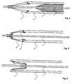
- a guide catheter 1 is shown with a first embodiment of a screen 2.
- the screen has the shape of a hollow cone with substantially conical inner and outer surfaces.
- a hollow-cylindrical projection is shown, which in turn has a substantially conical tip, which prevents a jump in velocity between the guide catheter 1 and the screen 2.
- the screen 2 is located on the guide catheter 1 at the level of the safety stopper or instead of the safety stopper, which ensures in the known insertion aids that the insertion aid can not be accidentally pushed completely over the guide catheter 1.
- the safety stopper of conventional guide catheters is a thickening of the catheter tube. If the screen is mounted in the device according to the invention so that such a thickening is immediately proximal to the tip of the screen, so the tip of the screen is particularly stabilized and facilitates the attachment of the screen, without the retractability of the catheter with the screen through the Restrict tracheal cannula.
- FIG. 2 shows a longitudinal section through a further embodiment of a guide catheter 1 with a screen 2.
- the shield 2 has a thin-walled at its distal end hollow cylindrical approach, which is tapered.
- the approach is an elongated tip of the conical screen 2 and causes between screen 2 and guide catheter 1, a sufficient area is available to connect them by gluing or welding together.
- the screen shown here has at its base a hollow cylindrical projection whose outer diameter is smaller than the diameter of the base of the screen and whose inner diameter is greater than the outer diameter of the displacement body.
- the inner surface of the lug is a continuation of the inner surface of the shield 2 and the lug tapers in the proximal direction.
- FIG. 3 is a longitudinal section of the distal end of a tracheostomy tube 4, a guide catheter 1 with a further embodiment of a screen 2 and a displacement body 3 is shown.
- the projection at the base of the screen 2 is located between the cannula tube 4 and the displacement body 3.
- the displacement body 3 thus fixes the screen 2 in a position in which the screen 2 the Kaliberspang between the guide catheter 1 and the displacement body 3 with the cannula tube 4th balances. This also prevents that when inserting the cannula 4 by means of the device according to the invention the screen 2 folds over too early or deforms.
- the base of the screen 2 covers the distal end face 5 of the cannula tube 4 completely and thereby prevents injuries that may occur when this area is trapped on the trachea.
- the longitudinal section clearly shows that the displacement body 3 must have a central lumen for receiving the guide catheter 1. It is otherwise not possible that the guide catheter 1 with screen 2 and the displacement body 3 are located simultaneously within the cannula 4.
- the displacement body could also consist solely of a conical tip, if appropriate, with a short hollow cylindrical approach, which is connected via a hose or one or more puller wires or threads with the proximal side of this tip, and in this way from the in FIG. 3 can be withdrawn position shown.
- FIG. 4 shows the distal end of a cannula 4 with displacement body 3 and the guide catheter 1 with screen 2 FIG. 3 ,
- the displacement body 3 is slightly displaced in the direction of the proximal end of the cannula 4, so that the fixation of the screen 2 and the fixation of the displacement body 3 is canceled even within the cannula 4.
- the base of the umbrella could, depending on the configuration of the end face of the cannula and the base surface of the shield adjacent thereto, fold inwardly and slide into the cannula.
- FIG. 5 is the cannula 4 with the guide catheter 1 and the screen 2 off FIG. 3 shown.
- the displacement body 3 was already removed from the tracheostomy tube.
- By slightly retracting the guide catheter 1 in the proximal direction of the screen 2 is inverted from the first state in which it bridges the jump between the cannula and the displacement body, from the top inwardly into the second state, in which the guide catheter 1 with the screen 2 by the cannula 4 is retractable, wherein it initially covers the distal end face 5 of the cannula 4.
- FIG. 6 shows the cannula 4 with the guide catheter 1 and the screen 2 FIG. 3 , wherein the screen is finally in the second state.
- the screen 2 By retracting the guide catheter 1 in the direction of the proximal end of the cannula 4, the screen 2 was deformed until it was completely everted. In this case, the screen in its base region also quite throw wrinkles (not shown) In this everted state, the screen 2 can be withdrawn through the cannula 4 in the direction of the proximal end.
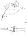
- FIG. 7 is shown as a guide catheter 1 with screen 2 in an embodiment as in FIG. 1 represented, from the distal end into a cannula 4, in which an insertion aid 3 is located as a displacement body, is inserted.
- This displacement body is a common insertion aid 3 with an annular projection 13, which prevents the insertion aid is pushed too far towards the distal end of the cannula 4.
- FIG. 8 represents an embodiment of a screen 2.
- the screen is characterized by a particularly large wall thickness, which can be between 1.5 and 4 mm.
- the base of the umbrella goes from a flat surface into a grooved, arched shape.
- the screen can be made of a compressible material so that the guide catheter 1 is easier to retract together with this screen 2 through a tracheal cannula.
- the guide catheter 1 is designed in this embodiment of the screen so that it has a larger outer diameter proximal of the screen.
- the catheter thus assumes the function of a displacement body and thus contributes to the stabilization of the screen during insertion of the tracheostomy tube into the trachea of the patient.
- the base of the shield encloses a smaller outer diameter catheter section and is thereby sufficiently compressible or deformable to be withdrawn through the cannula.
Landscapes
- Health & Medical Sciences (AREA)
- Pulmonology (AREA)
- Life Sciences & Earth Sciences (AREA)
- General Health & Medical Sciences (AREA)
- Veterinary Medicine (AREA)
- Biomedical Technology (AREA)
- Heart & Thoracic Surgery (AREA)
- Public Health (AREA)
- Engineering & Computer Science (AREA)
- Animal Behavior & Ethology (AREA)
- Emergency Medicine (AREA)
- Hematology (AREA)
- Anesthesiology (AREA)
- Surgery (AREA)
- Gastroenterology & Hepatology (AREA)
- Pathology (AREA)
- Nuclear Medicine, Radiotherapy & Molecular Imaging (AREA)
- Medical Informatics (AREA)
- Molecular Biology (AREA)
- Otolaryngology (AREA)
- Media Introduction/Drainage Providing Device (AREA)
- Surgical Instruments (AREA)
Description
Die vorliegende Erfindung betrifft eine Vorrichtung mit einem Führungskatheter zum Einbringen einer Trachealkanüle in ein Tracheostoma mit einem Führungskatheter. Eine derartige Einführhilfe mit Führungskatheter ist aus der
Die Methode der Tracheotomie findet sowohl in der Notfalimedizin als auch bei der Langzeitbeatmung Anwendung. Als Alternative zu der klassischen operativen Technik wurden innerhalb der letzten Jahrzehnte auch verschiedene perkutane Tracheotomietechniken entwickelt, insbesondere die perkutane Dilatationstracheotomie.The method of tracheotomy is used in emergency medicine as well as in long-term ventilation. As an alternative to the classical surgical technique, various percutaneous tracheostomy techniques have been developed within the last decades, in particular the percutaneous dilatation tracheotomy.
Bei der perkutanen Dilatationstracheotomie nach Ciaglia bzw. Griggs oder Frova wird über eine Punktionsnadel zunächst ein Führungsdraht in die Luftröhre eingebracht. Nach Dilatation mit einem 14 French 4,67 mm Dilatator kann der Führungsdraht durch Überziehen eines Führungskatheters verstärkt werden. Die Einheit aus Führungsdraht und Führungskatheter dient dann als Leitschiene zur Dilatation des trachealen Punktionskanals mit Hilfe eines gebogenen konischen Dilatators, einer Zange oder eines schraubenförmigen Dilatators. Nach entsprechendem Aufweiten des Punktionskanals und anschließendem Entfernen des Dilatators kann die Tracheotomiekanüle in analoger Weise unter Verwendung von Führungsdraht und Führungskatheter als Leitschiene mit Hilfe einer dafür vorgesehenen Efnführhüfe eingesetzt werden. Beim Kanülenwechseln kann analog vorgegangen werden, wobei auf einen Führungsdraht verzichtet werden kann.In the percutaneous dilatation tracheotomy according to Ciaglia or Griggs or Frova, a guide wire is first inserted into the trachea via a puncture needle. After dilatation with a 14 French 4.67 mm dilator, the guidewire can be reinforced by coating a guide catheter. The guidewire and guiding catheter assembly then serves as a guide for dilating the tracheal puncture channel by means of a curved conical dilator, forceps, or helical dilator. After appropriate widening of the puncture channel and subsequent removal of the dilator, the tracheostomy tube can be used in an analogous manner using guide wire and guide catheter as a guide rail with the aid of a dedicated Efnführhüfe. When changing cannula can be proceeded analogously, which can be dispensed with a guide wire.
Das Einsetzen der Tracheostomiekanüle nach dem Entfernen des Dilatators sollte dabei sehr schnell erfolgen, da der Patient während dieser Zeit in der Regel nicht beatmet wird. Außerdem besteht das Risiko einer Blutung, da der Druck auf das aufgeweitete Stoma während der Entnahme des Dilatators reduziert wird. Ein weiteres Problem besteht darin, daß sich das Stoma nach erfolgter Dilatation wieder zusammenzieht. Um dies zu kompensieren wird das Stoma bei der Dilatation meist deutlich weiter aufgedehnt als es der Außendurchmesser der Trachealkanüle erfordern würde. Durch diese starke Dilatation steigt das Risiko von Trachealspangenfrakturen.The insertion of the tracheostomy tube after removal of the dilator should be done very quickly because the patient is usually not ventilated during this time. In addition, there is a risk of bleeding as the pressure on the dilated stoma is reduced during removal of the dilator. Another problem is that the stoma contracts again after dilatation. To compensate for this, the stoma is dilated much more dilatation than the outer diameter of the tracheal cannula would require. This strong dilatation increases the risk of tracheal sphincter fractures.
Um die Tracheotomiekanüle in das bei der perkutanen Dilatationstracheotomie sehr eng angelegte Tracheostoma einführen zu können, verwendet man eine Einführhilfe, deren maximaler Außendurchmesser geringfügig kleiner ist als der Innendurchmesser der Kanüle und deren Spitze ähnlich wie bei den Dilatatoren am distalen Ende (Patientenende) konisch verjüngt ist und die vom proximalen Ende (Arztende) her in die Kanüle eingeführt wird. In diesem Fall gibt es jedoch einen stufenförmigen Kalibersprung am Übergang zwischen der aus dem distalen Ende der Kanüle herausstehenden Einführhilfe und dem Außendurchmesser an der Stirnseite der Kanülenwand. Bei Kanülen mit dicken Wänden kann dieser abrupte Übergang ein ernsthaftes Problem darstellen. Bei dem Versuch die Kanüle einzusetzen, bleibt die Stirnwand der Kanüle häufig an einer der Trachealspangen hängen. Dabei kann es zu einer Fraktur von Knorpelspangen bzw. zu einer Verletzung der Trachearückwand kommen. Einige Hersteller von Tracheotomiekanülen haben versucht, dieses Problem zu lösen, indem sie die Stirnwand der Kanüle konisch nach innen verjüngt haben. Eine Einführhilfe mit einem Führungskatheter, die eine sich am Patientende konisch verjüngende Spitze aufweist und die vom Arztende in die Tracheotomiekanüle eingeführt wird, mit einer Tracheotomiekanüle mit einer solchen konischen Verjüngung der Stirnwand und zusätzlich mit einer geneigt zur Achse verlaufenden Abschrägung des Kanülenendes ist auch im Falle der eingangs genannten
In der noch nicht veröffentlichten
Aus der
Aus der
Aus der
Ein weiteres Problem besteht darin, daß das Verhältnis zwischen freier Querschnittsfläche und Wandstärke der konischen Spitze sehr ungünstig wird, wenn der Innendurchmesser einer Tracheotomiekanüle weniger als 8 mm beträgt, und die konische Spitze dadurch nur sehr schwer in den Zustand mit kleinem Basisdurchmesser gebracht werden kann.Another problem is that the ratio between free cross-sectional area and wall thickness of the conical tip becomes very unfavorable when the inner diameter of a tracheostomy tube is less than 8 mm, and the conical tip is very difficult to be brought into the state with a small base diameter.
Bei bekannten Trachealkanülen mit Einführhilfen besteht zusätzlich das Problem, daß die Einführhilfe nach dem Einsetzen der Trachealkanüle in die Trachea des Patienten nur schwer rückziehbar ist. Dies ist insbesondere dann der Fall, wenn sehr wenig Spiel zwischen der Einführhilfe und der Trachealkanüle vorhanden ist. Auch bei handelsüblichen weichen Kanülen aus Silikon oder PVC und bei Kanülen, deren Biegung so ausgeführt ist, daß die Einführhilfe während des Herausziehens deformiert werden muß, ist das Entfernen der Einführhilfe nur mit erheblichem Kraftaufwand möglich. Dieses Problem kann zwar durch die Verwendung von Gleitmitteln reduziert werden, es besteht jedoch das Risiko, daß der behandelnde Arzt diesen Arbeitsschritt versehentlich überspringt.In the case of known tracheostomy tubes with insertion aids, there is additionally the problem that the insertion aid is difficult to retract after insertion of the tracheal cannula into the trachea of the patient. This is especially the case when there is very little play between the introducer and the tracheal cannula is present. Even with commercially available soft silicone or PVC needles and cannulas whose bending is designed so that the insertion must be deformed during extraction, the removal of the insertion is possible only with considerable effort. Although this problem can be reduced by the use of lubricants, there is a risk that the attending physician may accidentally skip this procedure.
Ausgehend von diesem Stand der Technik liegt der vorliegenden Erfindung die Aufgabe zugrunde, eine Vorrichtung zum Einbringen einer Trachealkanüle in ein Tracheostoma zur Verfügung zu stellen, die eine Verletzung durch die distale stirnseitige Fläche der Kanüle verhindert und die geeignet ist für die Anwendung bei sehr flexiblen Kanülen, bei Kanülen mit engem Innendurchmesser und/oder mit großer Wandstärke. Vorzugsweise soll eine Vorrichtung zu Verfügung gestellt werden, mit der auch die Dilatation des Stomas und das Einbringen der Trachealkanüle in einem Schritt durchgeführt werden kann.Based on this prior art, the present invention has the object to provide a device for introducing a tracheostomy tube into a tracheostomy, which prevents injury from the distal end face of the cannula and which is suitable for use in very flexible cannulas , for cannulas with a narrow inner diameter and / or with a large wall thickness. Preferably, a device is to be made available, with which the dilation of the stoma and the insertion of the tracheal cannula can be performed in one step.
Diese Aufgabe wird dadurch gelöst, daß der Führungskatheter einen Schirm aufweist, der in der Nähe des distalen Endes des Führungskatheters an diesem angebracht ist und der aus einem flexiblen Material besteht und im wesentlichen die Form einer distal gerichteten konischen Spitze hat, wobei das Rohr des Führungskatheters durch die Achse dieser Spitze verläuft, mit einem Basisaußendurchmesser, der in einem ersten Zustand in etwa dem Außendurchmesser der Trachealkanüle entspricht und in einem zweiten Zustand durch Verformung kleiner ist als der Innendurchmesser der Trachealkanüle und damit durch die Trachealkanüle rückziehbar ist,_wobei ein hohlzylinderförmiger Verdrängungskörper, dessen Außendurchmesser kleiner ist als der Innendurchmesser der Kanüle und der in der Kanüle über den Führungskatheter aufschiebbar ist, in dem ersten Zustand mit einer Innenfläche des Schirms in Eingriff steht.This object is achieved in that the guide catheter has a screen which is attached thereto in the vicinity of the distal end of the guide catheter and which consists of a flexible material and has substantially the shape of a distally directed conical tip, wherein the tube of the guide catheter extends through the axis of this tip, with a base outer diameter, which in a first state corresponds approximately to the outer diameter of the tracheal cannula and in a second state by deformation is smaller than the inner diameter of the tracheal cannula and thus retractable by the tracheal cannula, _wobei a hollow cylindrical displacement body, the outer diameter of which is smaller than the inner diameter of the cannula and which is slidable in the cannula via the guide catheter, in the first state is engaged with an inner surface of the shield.
Der erste und der zweite Zustand sollen dabei wahlweise einstellbar sein.The first and the second state should be selectively adjustable.
Der Begriff "konisch" ist nicht im streng geometrischen Sinne zu verstehen, sondern bezieht sich im wesentlichen auf einen von der Spitze zur Basis hin zunehmenden Durchmesser ohne sprunghafte Aufweitung, wobei die Kontur des "Konus" auch konkav oder konvex gewölbt sein kann.The term "conical" is not to be understood in the strict geometric sense, but refers essentially to an increasing diameter from the tip to the base without sudden expansion, wherein the contour of the "cone" may also be concave or convex.
Der Begriff "Basis" bezeichnet die Ebene des Schirms senkrecht zu seiner Achse, die den größten Durchmesser hat.The term "base" refers to the plane of the screen perpendicular to its axis, which has the largest diameter.
Der Begriff "distal" bezeichnet dabei das dem Patienten zugewandte Ende, also das Ende, das in den Patienten eingeführt wird, im Gegensatz zu "proximal", womit das dem Arzt zugewandte Ende bezeichnet wird.The term "distal" refers to the end facing the patient, ie the end that is introduced into the patient, in contrast to "proximal", which means the end facing the doctor.
Selbstverständlich ist dabei der Schirm auf dem Katheter so angeordnet, daß während des Einführens des Katheters in das Tracheostoma, mit oder ohne die Kanüle, die Spitze des Schirms in Richtung des distalen Endes des Katheters zeigt und die Basis dementsprechend proximal gelegen ist.Of course, the screen is positioned on the catheter so that during insertion of the catheter into the tracheostoma, with or without the cannula, the tip of the shield points towards the distal end of the catheter and the base is accordingly proximally located.
Ein Vorteil der erfindungsgemäßen Vorrichtung besteht darin, daß die distale Stirnfläche der Kanülenwand durch den Schirm vollständig abgedeckt wird und dadurch eine Verletzung beim Einbringen der Kanüle vermieden werden kann. Vor der Verwendung dieser Vorrichtung wird der Führungskatheter mit dem Schirm vom distalen Ende her in die Trachealkanüle eingeführt. Der Schirm kann dadurch optimal plaziert werden und muß erst nach dem Einsetzen der Trachealkanüle in die Luftröhre des Patienten durch die Kanüle hindurch zurückgezogen werden. Eine Anbringung des Schirmes ist auf jedem beliebigen Katheter, der für diesen Zweck geeignet ist, möglich. Das distale Ende des Führungskatheters sollte dabei möglichst weich und abgerundet sein, um Verletzungen vorzubeugen.An advantage of the device according to the invention is that the distal end face of the cannula wall is completely covered by the screen and thereby injury during insertion of the cannula can be avoided. Before using this device, the guiding catheter with the shield is inserted from the distal end into the tracheostomy tube. The umbrella can thus be optimally placed and must be retracted only after the insertion of the tracheostomy tube into the trachea of the patient through the cannula. An attachment of the screen is possible on any catheter that is suitable for this purpose. The distal end of the guide catheter should be as soft and rounded as possible to prevent injury.
Die Änderung des Zustands des Schirms erfolgt dabei vorzugsweise durch gezielte Relativbewegung zwischen Führungskatheter und Kanüle, also beispielsweise durch Festhalten der eingesetzten Kanüle und Zurückziehen des Führungskatheters.The change in the state of the screen is preferably carried out by targeted relative movement between the guide catheter and cannula, so for example by holding the inserted cannula and retraction of the guide catheter.
Selbstverständlich ist die erfindungsgemäße Vorrichtung auch beim Einsetzen anderer Tuben in künstliche oder natürliche Körperöffnungen beispielsweise beim Einbringen von Endotrachealtuben anwendbar.Of course, the device according to the invention is also applicable to the insertion of other tubes in artificial or natural body orifices, for example when introducing Endotrachealtuben.
Mit Hilfe der erfindungsgemäßen Vorrichtung kann nach erfolgter Vordilatation (z.B. mit einem üblichen 14 French Dilatator) die Dilatation und das Einführen der Trachealkanüle in einem Schritt erfolgen. Selbstverständlich ist es auch möglich, die Vorrichtung nach der Dilatation mit handelsüblichen Dilatatoren einzusetzen.With the aid of the device according to the invention, after pre-dilatation (for example with a standard 14 French dilator), the dilatation and the insertion of the tracheal cannula can take place in one step. Of course, it is also possible to use the device after dilation with commercially available dilators.
Die erfindungsgemäße Vorrichtung hat weiterhin den Vorteil, daß der Führungskatheter aufgrund des daran befestigten Schirms nicht vom distalen Ende in die Einführhilfe oder den Dilatator verrutschen kann. Dies vermindert zusätzlich das Risiko von Verletzungen, da in diesen Fällen die Möglichkeit bestünde, daß der ungeschützte Führungsdraht abknicken und dadurch die Einführhilfe oder der Dilatator die Rückwand der Trachea verletzen könnte.The device according to the invention also has the advantage that the guide catheter can not slip from the distal end into the insertion aid or the dilator due to the screen attached thereto. This additionally reduces the risk of injury, since in these cases there is a possibility that the unprotected guidewire could break and thus the introducer or dilator could injure the posterior wall of the trachea.
Es ist hierzu bevorzugt, daß der äußere Basisdurchmesser des Schirms in dem ersten Zustand dem Außendurchmesser der Trachealkanüle entspricht, eine Abweichung (insbesondere Verringerung) des Basisdurchmessers gegenüber dem Außendurchmesser der Kanüle um etwa 50% der Wandstärke der Trachealkanüle ist jedoch tolerierbar, insbesondere, wenn die Stirnseite der Kanüle abgerundet ist.It is preferred for this purpose that the outer base diameter of the screen in the first state corresponds to the outer diameter of the tracheal cannula, a deviation (in particular reduction) of the base diameter compared to the outer diameter of the cannula by about 50% of the wall thickness of the tracheal cannula is tolerable, especially if the End of the cannula is rounded.
In einer bevorzugten Ausführungsform hat der Schirm in dem ersten Zustand im wesentlichen die Form eines Hohlkegels und ist innen und außen konisch geformt. Die Ausformung des Schirms als Hohlkegel hat den Vorteil, daß es verschiedene Möglichkeiten der Verformung gibt, durch die der Schirm in den zweiten Zustand gebracht werden kann. Es ist möglich, daß der geringere Basisaußendurchmesser durch Eindellung der Hohlkegelwand, ähnlich dem Zusammenfalten eines Regenschirms, erreicht wird. Bevorzugt ist jedoch, daß der Schirm so ausgearbeitet ist, daß er sich von der Spitze her teilweise oder ganz umstülpt, um in den zweiten Zustand zu kommen.In a preferred embodiment, in the first state, the screen has substantially the shape of a hollow cone and is conically shaped inside and outside. The shape of the screen as a hollow cone has the advantage that there are various possibilities of deformation, by which the screen can be brought into the second state. It is possible that the smaller base outer diameter is achieved by denting the hollow cone wall, similar to the folding of an umbrella. However, it is preferred that the screen is designed so that it partially inverted from the top or completely to get into the second state.
Vorteilhaft ist es, wenn der Schirm eine maximale Wandstärke an der Basis von höchstens 2,5 mm, bevorzugt höchstens 1,5 mm, und wenigstens 0,4 mm, bevorzugt wenigstens 0,5 mm, aufweist. Diese Wandstärken sind dick genug, um dem Druck, der auf dem Schirm beim Einbringen der Kanüle in das Tracheostoma lastet, standzuhalten. Die Wandstärken sind aber auch dünn genug, damit der Schirm in den zweiten Zustand gebracht werden kann und dadurch problemlos durch die Trachealkanüle rückziehbar ist. Vorzugsweise verjüngt sich die Wand des Schirms von der Basis bis zur Spitze. Dadurch wird eine ausreichende Stabilisierung beim Einbringen der Trachealkanüle bei gleichzeitiger Rückziehbarkeit des Schirms durch die Kanüle erreicht.It is advantageous if the screen has a maximum wall thickness at the base of at most 2.5 mm, preferably at most 1.5 mm, and at least 0.4 mm, preferably at least 0.5 mm. These wall thicknesses are thick enough to withstand the pressure exerted on the screen during insertion of the cannula into the tracheostoma. The wall thicknesses are also thin enough so that the screen can be brought into the second state and thus easily retractable through the tracheostomy tube. Preferably, the wall of the umbrella tapers from the base to the top. As a result, sufficient stabilization is achieved when the tracheal cannula is inserted while the retractor of the umbrella is retractable through the cannula.
In einer bevorzugten Ausführungsform der Erfindung befindet sich die Basis des Schirms in einem Abstand von minimal 2, besser 5 bis 14 cm, bevorzugt 7 bis 10 cm, vom distalen Ende des Führungskatheters. Beim Einführen der Kanüle wird zunächst ein Führungsdraht in das Tracheostoma eingebracht, über den daraufhin der Führungskatheter eingeführt wird. Dieser Führungskatheter dient als Führung für das anschließende Einbringen der Trachealkanüle, er muß daher ausreichend weit in die Luftröhre hineinragen. Ein zu langes überstehendes distales Ende des Führungskatheters von der Trachealkanüle könnte andererseits zu Verletzungen der Luftröhre führen.In a preferred embodiment of the invention, the base of the screen is at a distance of at least 2, more preferably 5 to 14 cm, preferably 7 to 10 cm, from the distal end of the guide catheter. When inserting the cannula, a guidewire is first introduced into the tracheostomy, via which the guiding catheter is then introduced. This guide catheter serves as a guide for the subsequent introduction of the tracheostomy tube, he must therefore protrude sufficiently far into the trachea. On the other hand, too long a protruding distal end of the guide catheter from the tracheal cannula could lead to trauma to the trachea.
Bevorzugt beträgt die axiale Länge des Schirms zwischen 1 cm und 6 cm, besonders bevorzugt zwischen 1,5 cm und 3 cm. Ein Schirm mit einer größeren axialen Länge wäre aus sterischen Gründen nur sehr schwer oder gar nicht durch die Kanüle rückziehbar. Um jedoch ein möglichst schonendes Einführen zu ermöglichen und das Stoma nur langsam zu dehnen, soll der Schirm eine Mindestlänge von 1 cm aufweisen.Preferably, the axial length of the screen is between 1 cm and 6 cm, more preferably between 1.5 cm and 3 cm. A screen with a greater axial length would be steric Reasons very difficult or not retractable through the cannula. However, in order to allow the gentlest possible insertion and to stretch the stoma only slowly, the umbrella should have a minimum length of 1 cm.
Bevorzugt ist auch, daß der Konuswinkel zwischen dem Schirm und der Längsachse des Führungskatheters zwischen 3° und 30°, bevorzugt zwischen 5° und 15° beträgt. Schirme mit besonders kleinem Konuswinkel bewirken ein besonders schonendes Einführen in die Trachea bzw. eine langsame Dilatation des Stomas. Ein zu kleiner Winkel würde aber bei gegebenen Mindestdurchmessern von Kanülen zwangsläufig zu sehr langen Schirmen führen, die schwieriger zu handhaben wären.It is also preferred that the cone angle between the screen and the longitudinal axis of the guide catheter is between 3 ° and 30 °, preferably between 5 ° and 15 °. Umbrellas with a particularly small cone angle cause a particularly gentle insertion into the trachea or a slow dilatation of the stoma. A too small angle would inevitably lead to very long screens at given minimum diameters of cannulas, which would be more difficult to handle.
Gemäß einer besonderen Ausführungsform ist vorgesehen, daß ein hohlzylinderförmiger Verdrängungskörper, dessen Außendurchmesser kleiner ist als der Innendurchmesser der Kanüle und der in der Kanüle über den Führungskatheter aufschiebbar ist, in dem ersten Zustand mit einer Innenfläche des Schirms in Eingriff steht. Dieser Verdrängungskörper dient der Stabilisierung des Schirmes. Bei Verwendung des Verdrängungskörpers kann ein größerer Druck über den Schirm auf die Trachea ausgeübt werden, ohne daß der Schirm sich nennenswert verformt oder gar umstülpt, was das Aufweiten des Stomas erleichtert. Der Verdrängungskörper ist nach dem Einbringen der Trachealkanüle unabhängig von dem Führungskatheter zurückziehbar, wodurch der Führungskatheter in der Kanüle mehr Spiel erhält und das Zurückziehen des Führungskatheters mit dem verformten Schirm vereinfacht wird.According to a particular embodiment it is provided that a hollow cylindrical displacement body whose outer diameter is smaller than the inner diameter of the cannula and which can be pushed in the cannula via the guide catheter in the first state with an inner surface of the screen is engaged. This displacement body serves to stabilize the screen. When using the displacement body, a greater pressure can be exerted on the trachea via the screen, without the screen significantly deforming or even everting, which facilitates the expansion of the stoma. The displacer is retractable independently of the guide catheter after insertion of the tracheal cannula, whereby the guide catheter in the cannula receives more clearance and retraction of the guide catheter with the deformed screen is simplified.
Es besteht aber auch die Möglichkeit, den Verdrängungskörper so zu gestalten, daß er im wesentlichen aus einem kurzen Hohlzylinder besteht, dessen Durchmesser wenig geringer ist als der Innendurchmesser der Kanüle und der nach dem Einschieben im distalen Ende der Kanüle zu liegen kommt, an den ein flexibler röhrenförmiger Ansatz anschließt, der länger ist als die Kanüle und dem Einführen und Wiederherausziehen des Verdrängungskörpers dient.But it is also possible to make the displacement body so that it consists essentially of a short hollow cylinder whose diameter is less than the inner diameter of the cannula and comes to rest after insertion in the distal end of the cannula, to the one flexible tubular approach connects, which is longer than the cannula and the insertion and Wiederausausziehen the displacement body is used.
Bevorzugt ist auch eine Ausführungsform, bei der der Außendurchmesser des Verdrängungskörpers mindestens 0,2 mm, bevorzugt mindestens 1 mm und höchstens 4 mm, bevorzugt höchstens 1,5 mm kleiner ist als der Innendurchmesser der Trachealkanüle. Der Verdrängungskörper wird in der Regel vom proximalen Ende der Trachealkanüle eingeschoben. Ist sein Außendurchmesser kleiner als der Innendurchmesser der Trachealkanüle, so wird ein Einschieben auch bei Kanülen mit sehr flexiblen Wänden oder sehr kleinem Innendurchmesser erleichtert. Ist der Durchmesser des Verdrängungskörpers zu klein, so kann er den Schirm beim Einführen der Trachealkanüle nicht mehr ausreichend unterstützen.Also preferred is an embodiment in which the outer diameter of the displacement body is at least 0.2 mm, preferably at least 1 mm and at most 4 mm, preferably at most 1.5 mm smaller than the inner diameter of the tracheostomy tube. The displacer is usually inserted from the proximal end of the tracheostomy tube. If its outer diameter is smaller than the inner diameter of the tracheostomy tube, insertion is facilitated even with cannulas having very flexible walls or a very small inner diameter. If the diameter of the displacement body is too small, it can no longer adequately support the umbrella when inserting the tracheal cannula.
Besonders bevorzugt ist eine Ausführungsform, bei welcher die Basis des Schirms einen hohlzylinderförmigen Ansatz aufweist, mit einem Außendurchmesser, der dem Innendurchmesser der Kanüle angepaßt ist und diesen um maximal 10%, bevorzugt maximal 5%, bezogen auf den Innendurchmesser, über- oder unterschreitet, und mit einer Wandstärke, die zwischen 0,5 mm und 2 mm, bevorzugt zwischen 0,5 mm und 1 mm, beträgt. Durch diesen Ansatz entsteht eine Stufe zwischen der Basis der konischen Spitze und dem hohlzylinderförmigen Ansatz des Schirmes. Die radiale Tiefe der Stufe entspricht im ersten Zustand im wesentlichen der Dicke des Kanülenrohrs. Beim Einschieben des Führungskatheters mit dem Schirm vom distalen Ende in die Kanüle wird der Ansatz in das Kanülenrohr geschoben, während die Basis des Schirms auf der distalen Stirnfläche des Kanülenrohrs zu liegen kommt. Diese Ausführungsform bedingt eine verbesserte Stabilisierung des Schirms, so daß dieser bei Druck in Richtung des Kanülenrohrs nicht versehentlich umklappt oder zusammengestaucht wird. Auch ein Verschieben der Einführhilfe relativ zur Längsachse der Kanüle wird dadurch verhindert, wodurch dem Arzt ein kontrollierteres Einführen oder Dilatieren ermöglicht wird.Particularly preferred is an embodiment in which the base of the screen has a hollow cylindrical projection, with an outer diameter which is adapted to the inner diameter of the cannula and this by more than 10%, preferably not more than 5%, based on the inner diameter, exceeds or falls below, and with a wall thickness that is between 0.5 mm and 2 mm, preferably between 0.5 mm and 1 mm. This approach creates a step between the base of the conical tip and the hollow cylindrical projection of the screen. The radial depth of the stage corresponds in the first state substantially the thickness of the cannula tube. Upon insertion of the guide catheter with the shield from the distal end into the cannula, the lobes are pushed into the cannula tube while the base of the shield comes to rest on the distal end face of the cannula tube. This embodiment requires improved stabilization of the screen, so that it is not accidentally folded or compressed when pressure in the direction of the cannula tube. A displacement of the insertion relative to the longitudinal axis of the cannula is thereby prevented, whereby the doctor a more controlled insertion or dilatation is made possible.
Bei Verwendung eines Verdrängungskörpers ist es günstig, wenn der zylinderförmige Ansatz an der Basis des Schirms einen Außendurchmesser hat, der dem Innendurchmesser der Kanüle angepaßt ist und diesen um maximal 10%, bevorzugt maximal 5%, bezogen auf den Innendurchmesser über- oder unterschreitet, und einen Innendurchmesser, der im wesentlichen dem Außendurchmesser des Verdrängungskörpers entspricht oder etwas kleiner ist, aufweist. Dadurch befindet sich der hohlzylinderförmige Ansatz in dem ersten Zustand des Schirms zwischen dem Kanülenrohr und dem Verdrängungskörper. Zum Aufschieben des Schirms auf den Verdrängungskörper ist es dabei von Vorteil, wenn der hohlzylinderförmige Ansatz sich in proximaler Richtung verjüngt.When using a displacement body, it is advantageous if the cylindrical projection at the base of the screen has an outer diameter which is adapted to the inner diameter of the cannula and this by more than 10%, preferably not more than 5%, based on the inner diameter exceeds or falls below, and an inner diameter substantially equal to or slightly smaller than the outer diameter of the displacer. As a result, the hollow cylindrical projection is in the first state of the screen between the cannula tube and the displacement body. For pushing the screen on the displacement body, it is advantageous if the hollow cylindrical neck tapers in the proximal direction.
Bevorzugt ist weiterhin eine Vorrichtung, bei der die axiale Länge des hohlzylinderförmigen Ansatzes an der Basis des Schirmes zwischen 0,3 und 5 mm, bevorzugt zwischen 1 und 3 mm, beträgt. Für eine optimale Stabilisierung zur Verhinderung des Zusammenklappens des Schirms während des Eindringens der Kanüle muß der hohlzylinderförmige Ansatz ausreichend lang sein. Ein zu langer Ansatz könnte hingegen bei der Verformung des Schirmes hinderlich sein oder diese womöglich gänzlich verhindern.Also preferred is a device in which the axial length of the hollow cylindrical projection at the base of the screen between 0.3 and 5 mm, preferably between 1 and 3 mm. For optimum stabilization to prevent collapse of the shield during penetration of the cannula, the hollow cylindrical extension must be sufficiently long. A too long approach, however, could be a hindrance to the deformation of the screen or possibly completely prevent them.
Bevorzugt ist auch eine Ausführungsform, bei der der Verdrängungskörper an seinem distalen Ende eine konische Spitze aufweist. Zweckmäßig ist es, wenn diese Spitze komplementär zu einer konischen Innenfläche des Schirmes ausgebildet ist. Dadurch wird der Schirm beim Einführen der Kanüle besonders gut stabilisiert.An embodiment in which the displacement body has a conical tip at its distal end is also preferred. It is useful if this tip is complementary to a conical inner surface of the screen is formed. As a result, the screen is stabilized particularly well when inserting the cannula.
Besonders bevorzugt besteht der Schirm aus einem im wesentlichen elastischen Material. Wird ein solcher elastischer Schirm zusammen mit einem Verdrängungskörper verwendet, so sollte der Schirm einen Innendurchmesser aufweisen, der den Außendurchmesser des Verdrängungskörpers um 0-40%, bevorzugt 20-30%, bezogen auf den Außendurchmesser des Verdrängungskörpers unterschreitet. Dadurch besteht die Möglichkeit, daß der Schirm über die Spitze des Verdrängungskörpers gespannt werden kann, was die Stabilität und den Halt des Schirmes und des Verdrängungskörpers erhöht, insbesondere wenn ein Schirm mit einem hohlzylinderförmigen Ansatz an der Basis verwendet wird. Bei der Verwendung eine elastischen Schirms in der erfindungsgemäßen Vorrichtung kann der zweite Zustand des Schirms dem ungespannten Zustand des Schirms entsprechen. Ein solcher Schirm ist ohne Umstülpen durch die Trachealkanüle rückziehbar.Particularly preferably, the screen consists of a substantially elastic material. If such an elastic screen is used together with a displacement body, then the screen should have an inner diameter that falls below the outer diameter of the displacement body by 0-40%, preferably 20-30%, based on the outer diameter of the displacement body. As a result, there is a possibility that the screen can be stretched over the tip of the displacer, which increases the stability and the hold of the screen and the displacer, especially when a screen with a hollow cylindrical projection is used at the base. When using an elastic screen in the device according to the invention, the second state of the screen can correspond to the unstressed state of the screen. Such a screen is retractable without everting through the tracheostomy tube.
Weiterhin ist eine Ausgestaltung der Erfindung bevorzugt, bei welcher der Schirm und/oder der Verdrängungskörper einen im wesentlichen ovalen Querschnitt aufweist. Der Schirm und/oder der Verdrängungskörper sollten dabei so ausgerichtet werden, daß ihre Ausdehnung senkrecht zu den Trachealspangen des Patienten kleiner ist, als in Richtung des Verlaufs der Trachealspangen. Dies kann beispielsweise allein oder überwiegend durch eine senkrecht zu den Trachealspangen verringerte bzw. parallel zu den Trachealspangen vergrößerte Wandstärke erreicht werden, wobei die Differenz der Wandstärken beispielsweise zwischen 0,25 mm und 1 mm betragen kann. Da ein Aufdehnen des Stomas senkrecht zu den Trachealspangen schwieriger ist, als zwischen den Spangen, kann diese Ausführungsform leichter in das Stoma eingeführt werden oder eine einfachere Dilatation des Stomas bewirken. Ein weiterer Vorteil dieser Ausführungsform besteht darin, daß die Trachealkanüle, die in der Regel einen runden Querschnitt aufweist, durch einen ovalen Schirm und/oder ovalen Verdrängungskörper in Richtung der Trachealspangen aufgeweitet und/oder senkrecht dazu reduziert werden kann. Diese ovale Deformation erleichtert das Einführen der Kanüle in die Trachea wie oben erläutert. Dies wird insbesondere dann erreicht, wenn der Verdrängungskörper einen ovalen Querschnitt aufweist. Wird der Verdrängungskörper entfernt, so nimmt die Trachealkanüle wieder ihre ursprüngliche runde Querschnittsform an. Die gleiche Wirkung kann durch einen Verdrängungskörper erzielt werden, der wenigstens am distalen Ende eine ovale Form aufweist.Furthermore, an embodiment of the invention is preferred in which the screen and / or the displacement body has a substantially oval cross-section. The screen and / or the displacement body should be aligned so that their extension is perpendicular to the tracheal braces of the patient is smaller than in the direction of the course of Trachealspangen. This can be achieved, for example, solely or predominantly by a wall thickness reduced perpendicular to the tracheal braces or enlarged parallel to the tracheal braces, wherein the difference in the wall thicknesses can be, for example, between 0.25 mm and 1 mm. Since stretching the stoma perpendicular to the tracheal braces is more difficult than between the braces, this embodiment can be more easily inserted into the stoma or cause easier dilatation of the stoma. A further advantage of this embodiment is that the tracheal cannula, which generally has a round cross-section, can be widened and / or reduced perpendicularly in the direction of the tracheal braces by an oval shade and / or an oval displacement body. This oval deformation facilitates insertion of the cannula into the trachea as explained above. This is achieved in particular when the displacement body has an oval cross-section. When the displacer is removed, the tracheal cannula returns to its original round cross-sectional shape. The same effect can be achieved by a displacement body having an oval shape at least at the distal end.
Besonders bevorzugt ist eine Ausführungsform, bei der der Verdrängungskörper eine herkömmliche Einführhilfe ist. Die aus dem Stand der Technik bekannten Einführhilfen, bei denen zwischen Einführhilfe und distalem Ende der Kanüle eine Stufe auftritt, stellen eine spezielle Ausführung eines Verdrängungskörpers dar. Durch die Verwendung solcher herkömmlicher Einführhilfen verringern sich die Kosten der Herstellung der erfindungsgemäßen Vorrichtung, da bereits auf dem Markt befindliche Kanülen mit Einführhilfe verwendet werden können und lediglich ein Führungskatheter mit dem erfindungsgemäßen Schirm den herkömmlichen Katheter ersetzen muß.Particularly preferred is an embodiment in which the displacement body is a conventional insertion aid. The known from the prior art insertion aids, in which between Insertion aid and distal end of the cannula occurs a step, represent a special embodiment of a displacement body. Through the use of such conventional insertion aids, the cost of manufacturing the device according to the invention are reduced, since already on the market cannulas with insertion can be used and only a guide catheter must replace the conventional catheter with the screen according to the invention.
Vorzugsweise besteht der Schirm aus einem elastischen Material wie Silikon, einem thermoplastischen Elastomer (TPE), Latex oder Polyurethan. Diese Materialien sind geeignet, um einen ausreichend flexiblen und gegebenenfalls elastischen Schirm herzustellen, der gleichzeitig über die notwendige Stabilität verfügt. Im übrigen können diese Materialien entsprechend den Anforderungen im medizinischen Bereich behandelt werden, so daß sie steril sind.Preferably, the screen is made of an elastic material such as silicone, a thermoplastic elastomer (TPE), latex or polyurethane. These materials are suitable to produce a sufficiently flexible and optionally elastic screen, which also has the necessary stability. Incidentally, these materials may be treated according to the requirements of the medical field, so that they are sterile.
Bevorzugt ist auch eine Ausführungsform, bei der der Schirm mit einer hydrophilen Beschichtung versehen ist. Eine solche Beschichtung hat vorzugsweise nach Befeuchtung einen geringen Reibungskoeffizienten und erleichtert dadurch das Einführen dar Kanüle. Selbstverständlich ist es ausreichend, wenn die Außenfläche des Schirms mit einer solchen Beschichtung überzogen ist. Alternativ dazu kann der Schirm auch auf seiner Außenfläche mit Gleitgel benetzt sein, dies hat die gleiche Funktion wie die oben beschriebene Beschichtung.An embodiment in which the screen is provided with a hydrophilic coating is also preferred. Such a coating preferably has a low coefficient of friction after moistening and thereby facilitates insertion of the cannula. Of course, it is sufficient if the outer surface of the screen is coated with such a coating. Alternatively, the screen may also be wetted with lubricant on its outer surface, this has the same function as the coating described above.
Weiterhin bevorzugt ist eine Ausführungsform, bei der die Spitze des Schirmes einen hohlzylinderförmigen Ansatz aufweist. Dieser Ansatz dient im wesentlichen der Befestigung des Schirmes an dem Führungskatheter. Er kann seinerseits über eine konische Spitze verfügen, so daß zwischen dem Führungskatheter und diesem distalen Ansatz kein Kalibersprung vorhanden ist. Besonders vorteilhaft ist es, wenn die konische Spitze einer Verlängerung des Schirms darstellt und die Außenflächen der Spitze und des Schirms dadurch eine durchgehende Fläche ohne ausgeprägten Übergang bilden.Further preferred is an embodiment in which the tip of the screen has a hollow cylindrical projection. This approach is essentially the attachment of the screen to the guide catheter. For its part, it can have a conical tip so that there is no change in the caliber between the guiding catheter and this distal approach. It is particularly advantageous if the conical tip represents an extension of the screen and the outer surfaces of the tip and the screen thereby form a continuous surface without pronounced transition.
Besonders bevorzugt ist eine Ausführungsform, bei welcher der Schirm durch Verkleben oder Verschweißen mit dem Führungskatheter verbunden ist. Diese Art der Befestigung ist stark genug, um ein Ablösen des Schirmes vom Führungskatheter beispielsweise während des Zurückziehens zu verhindern. Der Führungskatheter könnte auch - beispielsweise durch Spritzgießen - einstückig mit dem Schirm hergestellt werden.Particularly preferred is an embodiment in which the screen is connected by gluing or welding with the guide catheter. This type of attachment is strong enough to prevent detachment of the screen from the guide catheter during retraction, for example. The guide catheter could also be made in one piece with the screen, for example by injection molding.
Weitere Vorteile, Merkmale und Anwendungsmöglichkeiten der vorliegenden Erfindung werden deutlich anhand der folgenden Beschreibung bevorzugter Ausführungsformen und den dazu gehörigen Figuren. Es zeigen:
Figur 1- einen Führungskatheter mit Schirm in einer ersten Ausführungsform,
Figur 2- einen Führungskatheter mit einem Schirm in einer weiteren Ausführungsform,
Figur 3- einen Längsschnitt durch eine Trachealkanüle mit Führungskatheter, Verdrängungskörper und Schirm in einem ersten Zustand,
Figur 4- einen Längsschnitt durch eine Trachealkanüle mit Führungskatheter, Verdrängungskörper und Schirm, wobei der Verdrängungskörper zurückgezogen wird,
Figur 5- einen Längsschnitt durch eine Trachealkanüle mit Führungskatheter und Schirm beim Übergang von dem ersten zu dem zweiten Zustand,
Figur 6- einen Längsschnitt durch eine Trachealkanüle mit Führungskatheter und Schirm in dem zweiten Zustand,
Figur 7- eine Trachealkanüle, in die ein Führungskatheter mit Schirm eingeschoben wird, und
- Figur 8
- einen Führungskatheter mit Schirm in einer weiteren Ausführungsform
- FIG. 1
- a guide catheter with a screen in a first embodiment,
- FIG. 2
- a guide catheter with a screen in another embodiment,
- FIG. 3
- a longitudinal section through a tracheostomy tube with guide catheter, displacement body and screen in a first state,
- FIG. 4
- a longitudinal section through a tracheostomy tube with guide catheter, displacement body and screen, wherein the displacer is retracted,
- FIG. 5
- a longitudinal section through a tracheostomy tube with guide catheter and screen in the transition from the first to the second state,
- FIG. 6
- a longitudinal section through a tracheostomy tube with guide catheter and screen in the second state,
- FIG. 7
- a tracheostomy tube into which a guiding catheter with a screen is inserted, and
- FIG. 8
- a guide catheter with screen in another embodiment
In
Bei dem Sicherheitsstopper herkömmlicher Führungskatheter handelt es sich um eine Verdickung des Katheterrohres. Wird der Schirm bei der erfindungsgemäßen Vorrichtung so angebracht, daß sich eine solche Verdickung unmittelbar proximal der Spitze des Schirmes befindet, so wird dadurch die Spitze des Schirmes besonders stabilisiert und auch die Befestigung des Schirmes erleichtert, ohne die Rückziehbarkeit des Katheters mit dem Schirm durch die Trachealkanüle einzuschränken.The safety stopper of conventional guide catheters is a thickening of the catheter tube. If the screen is mounted in the device according to the invention so that such a thickening is immediately proximal to the tip of the screen, so the tip of the screen is particularly stabilized and facilitates the attachment of the screen, without the retractability of the catheter with the screen through the Restrict tracheal cannula.
In
In
In
Für Zwecke der ursprünglichen Offenbarung wird darauf hingewiesen, daß sämtliche Merkmale, wie sie sich aus der vorliegenden Beschreibung, den Zeichnungen und den Ansprüchen für einen Fachmann erschließen, auch wenn sie konkret nur im Zusammenhang mit bestimmten weiteren Merkmalen beschrieben wurden, sowohl einzeln als auch in beliebigen Zusammenstellungen mit anderen der hier offenbarten Merkmale oder Merkmalsgruppen kombinierbar sind, soweit dies nicht ausdrücklich ausgeschlossen wurde oder technische Gegebenheiten derartige Kombinationen unmöglich oder sinnlos machen. Auf die umfassende, explizite Darstellung sämtlicher denkbarer Merkmalskombinationen wird hier nur der Kürze und der Lesbarkeit der Beschreibung wegen verzichtet.For purposes of the original disclosure, it is to be understood that all such features as will become apparent to those skilled in the art from the present description, drawings, and claims, even though they have been specifically described only in connection with certain further features, both individually and separately any combination with other of the features or feature groups disclosed herein are combinable, unless this has been expressly excluded or technical conditions make such combinations impossible or pointless. On the comprehensive, explicit representation of all conceivable combinations of features is omitted here only for the sake of brevity and readability of the description.
Claims (13)
- A device having a guide catheter (1) for the introduction of a tracheal cannula (4) into a tracheostoma, wherein the guide catheter (1) has a shield (2) which is mounted in the proximity of the distal end of the guide catheter (1) and which comprises a flexible material and which is substantially in the form of a distally directed conical tip, wherein the tube of the guide catheter (1) passes through the axis of said tip, with a base outside diameter which in a first state corresponds approximately to the outside diameter of the tracheal cannula (4) and in a second state by deformation is smaller than the inside diameter of the tracheal cannula (4) and is thus retractable through the tracheal cannula, further comprising a displacement body (3) in the form of a hollow cylinder, the outside diameter of which is smaller than the inside diameter of the cannula (4) and which can be pushed on over the guide catheter (1) in the cannula and which is in engagement with an inside surface of the shield (2) in the first state.
- A device according to claim 1 characterised in that the shield (2) in the first state is substantially in the form of a hollow cone and is internally and externally conical.
- A device according to claim 1 or claim 2 characterised in that the shield (2) has a maximum wall thickness at the base of at most 2.5 mm, preferably at most 1.5 mm, and at least 0.4 mm, preferably at least 0.5 mm.
- A device according to one of the preceding claims characterised in that the base of the shield (2) is at a spacing of at least 2, better at least 5 to 14 cm, particularly preferably 7 to 10 cm from the distal end of the guide catheter (1).
- A device according to one of the preceding claims characterised in that the shield (2) is of an axial length of at least 1 cm, preferably at least 1.5 cm and at most 6 cm, preferably at most 3 cm.
- A device according to one of the preceding claims characterised in that the cone angle between the shield (2) and the longitudinal axis of the guide catheter (1) is between 3° and 30°, preferably between 5° and 15°.
- A device according to one of the preceding claims characterised in that the outside diameter of the displacement body (3) is at least 0.2 mm, preferably at least 1 mm and at most 4 mm, preferably at most 1.5 mm smaller than the inside diameter of the tracheal cannula (4).
- A device according to one of the preceding claims characterised in that the base of the shield (2) has an attachment in the form of a hollow cylinder, of an outside diameter which is adapted to the inside diameter of the cannula (4) and which is larger than or smaller than same by a maximum of 10%, preferably by a maximum of 5%, with respect to the inside diameter, and of a wall thickness which is between 0.5 mm and 2 mm, preferably between 0.5 and 1 mm.
- A device according to claim 8 characterised in that the axial length of the attachment in the form of a hollow cylinder is between 0.3 and 5 mm, preferably between 1 and 3 mm.
- A device according to one of the preceding claims characterised in that the displacement body (3) has a conical tip at its distal end.
- A device according to one of the preceding claims characterised in that the shield (2) consists of a substantially elastic material.
- A device according to one of the preceding claims characterised in that the tip of the shield (2) distally has an attachment in the form of a hollow cylinder.
- A device according to one of the preceding claims characterised in that the shield (2) is joined to the guide catheter (1) by adhesive or integrally by injection moulding or welding.
Applications Claiming Priority (2)
| Application Number | Priority Date | Filing Date | Title |
|---|---|---|---|
| DE102006029599A DE102006029599A1 (en) | 2006-06-26 | 2006-06-26 | Device for introducing a tracheostomy tube into a tracheostoma |
| PCT/EP2007/056262 WO2008000701A1 (en) | 2006-06-26 | 2007-06-22 | Device for inserting a tracheal cannula into a tracheostoma |
Publications (2)
| Publication Number | Publication Date |
|---|---|
| EP2032052A1 EP2032052A1 (en) | 2009-03-11 |
| EP2032052B1 true EP2032052B1 (en) | 2014-12-31 |
Family
ID=38480642
Family Applications (1)
| Application Number | Title | Priority Date | Filing Date |
|---|---|---|---|
| EP07765573.6A Active EP2032052B1 (en) | 2006-06-26 | 2007-06-22 | Device for inserting a tracheal cannula into a tracheostoma |
Country Status (6)
| Country | Link |
|---|---|
| US (1) | US8474459B2 (en) |
| EP (1) | EP2032052B1 (en) |
| JP (1) | JP4929351B2 (en) |
| CN (1) | CN101478925B (en) |
| DE (1) | DE102006029599A1 (en) |
| WO (1) | WO2008000701A1 (en) |
Families Citing this family (16)
| Publication number | Priority date | Publication date | Assignee | Title |
|---|---|---|---|---|
| GB2439928A (en) | 2006-07-13 | 2008-01-16 | Ethicon Inc | Hydrogel wound dressings exhibiting reduced fiber losses |
| CN102526852B (en) | 2010-12-29 | 2015-07-22 | 陈志扬 | Flat-head and side-hole tracheal catheter and lead core |
| ITMI20111820A1 (en) * | 2011-10-06 | 2013-04-07 | Enrico Giustiniano | ASSISTIVE DEVICE FOR ORO-TRACHEAL INTUBATION |
| CN103386161A (en) * | 2012-05-10 | 2013-11-13 | 陈志扬 | Guide core applied to retrograde tracheal intubation |
| US9615893B2 (en) * | 2012-11-14 | 2017-04-11 | Covidien Lp | Seal cleaning obturator |
| JP6298836B2 (en) | 2013-03-08 | 2018-03-28 | カンヌフロウ インコーポレイテッドCannuflow, Inc. | Arthroscopic flexible portal cannula device and feeding system |
| CN103479407B (en) * | 2013-10-18 | 2017-04-12 | 刘雅昕 | Closer guiding device |
| CN104287792B (en) * | 2014-09-29 | 2017-09-15 | 中国人民解放军第四军医大学 | For the skirt-type guiding tube in operation on esophagus |
| US9808282B2 (en) | 2015-06-04 | 2017-11-07 | Medos International Sarl | Surgical cannula system and method of use |
| DE102015122810A1 (en) | 2015-12-23 | 2017-06-29 | Tracoe Medical Gmbh | insertion |
| GB201607675D0 (en) * | 2016-04-30 | 2016-06-15 | Smiths Medical Int Ltd | Tracheostomy procedure kits and guiding catheters |
| DE202017002009U1 (en) | 2017-04-15 | 2017-06-02 | Primed Halberstadt Medizintechnik Gmbh | System for inserting a tracheostomy tube into a tracheostoma |
| US11172957B2 (en) | 2018-02-07 | 2021-11-16 | Stryker Corporation | Surgical cannula and methods of use |
| RU185713U1 (en) * | 2018-09-10 | 2018-12-14 | Общество с ограниченной ответственностью "Производственно-техническое объединение "МЕДТЕХНИКА" (ООО "ПТО "МЕДТЕХНИКА") | Device for conducting the opposite end of the venous cannula in soft tissues during minimally invasive heart surgery |
| CN109876276B (en) * | 2019-03-08 | 2021-09-17 | 济南市儿童医院(山东大学齐鲁儿童医院) | Children hemodialysis pipe fixing device |
| WO2021113962A1 (en) * | 2019-12-09 | 2021-06-17 | Mg Stroke Analytics Inc. | Systems and methods for accessing small arteries for conveying catheters to target vessels |
Family Cites Families (26)
| Publication number | Priority date | Publication date | Assignee | Title |
|---|---|---|---|---|
| US3769983A (en) * | 1970-08-26 | 1973-11-06 | A Meray | Medical devices |
| US4351330A (en) * | 1978-01-30 | 1982-09-28 | Scarberry Eugene N | Emergency internal defibrillation |
| DE3322001A1 (en) * | 1982-06-28 | 1983-12-29 | Walter 6222 Geisenheim Koss | Surgical instrument set |
| US4502482A (en) * | 1983-05-23 | 1985-03-05 | Deluccia Victor C | Endotracheal tube complex |
| US4655214A (en) * | 1984-06-28 | 1987-04-07 | Linder Gerald S | Inflatable introducer for aiding the intubation of catheters and endotracheal tubes |
| US4637388A (en) * | 1984-10-15 | 1987-01-20 | Portex, Inc. | Tracheal tube obturator with reversible tip |
| JPS62211074A (en) * | 1986-03-07 | 1987-09-17 | ボ−ド・オブ・リ−ジエンツ、ザ・ユニバ−シテイ−・オブ・テキサス・システム | Suction catheter with leading end balloon |
| US4846804A (en) * | 1988-03-24 | 1989-07-11 | Dlp Inc. | Combined needle protector and guidewire feeder |
| US5058580A (en) * | 1988-05-11 | 1991-10-22 | Hazard Patrick B | Percutaneous tracheostomy tube |
| US4978334A (en) * | 1988-09-08 | 1990-12-18 | Toye Frederic J | Apparatus and method for providing passage into body viscus |
| US4913139A (en) * | 1989-02-09 | 1990-04-03 | Ballew Donald H | Method of translaryngeal retrograde tracheal intubation |
| CA1324555C (en) * | 1989-06-13 | 1993-11-23 | Patrick B. Hazard | Percutaneous tracheostomy tube |
| JPH0339169A (en) * | 1989-07-06 | 1991-02-20 | B Hazaado Patrick | Percutaneous tracheotomic tube |
| JPH0326200U (en) * | 1989-07-26 | 1991-03-18 | ||
| GB9003857D0 (en) * | 1990-02-21 | 1990-04-18 | Smiths Industries Plc | Medico-surgical tube assemblies |
| US5188100A (en) * | 1991-09-09 | 1993-02-23 | New York University | Apparatus for facilitating tracheostomy tube replacement |
| DE9319838U1 (en) * | 1993-12-23 | 1994-02-10 | Greive Michael | Device for securing ends of catheter guidewires |
| CA2184958A1 (en) * | 1995-09-22 | 1997-03-23 | John S. Gentelia | Improved trocar-cannulla device |
| US5653230A (en) * | 1996-01-19 | 1997-08-05 | Cook Incorporated | Percutaneous balloon dilational tracheostomy tube |
| US5882345A (en) * | 1996-05-22 | 1999-03-16 | Yoon; Inbae | Expandable endoscopic portal |
| JP3899471B2 (en) * | 1997-04-15 | 2007-03-28 | 日本シャーウッド株式会社 | Double lumen catheter |
| IS7278A (en) * | 2001-11-26 | 2003-05-27 | Merlyn Associates, Inc. | Tracheal tubing with steerable end and positioning equipment |
| ATE373991T1 (en) * | 2002-07-31 | 2007-10-15 | Power Med Interventions Inc | INTRODUCTION DEVICE INTO AN OPENING |
| CN1234321C (en) * | 2003-10-21 | 2006-01-04 | 王永国 | Tracheal catheter guide tube |
| DE202005003601U1 (en) * | 2005-03-05 | 2005-05-19 | Neubauer, Norbert | Tracheotomy tube used as an artificial larynx comprises a fixed or removable elastic sealing umbrella with a flexible, spreadable umbrella spider that is introduced through an insertion ring into a stoma |
| DE102005021470A1 (en) | 2005-05-10 | 2006-11-16 | Tracoe Medical Gmbh | Introducer for percutaneous tracheostomy |
-
2006
- 2006-06-26 DE DE102006029599A patent/DE102006029599A1/en not_active Ceased
-
2007
- 2007-06-22 WO PCT/EP2007/056262 patent/WO2008000701A1/en active Application Filing
- 2007-06-22 US US12/305,430 patent/US8474459B2/en active Active
- 2007-06-22 JP JP2009517138A patent/JP4929351B2/en active Active
- 2007-06-22 CN CN200780023849.9A patent/CN101478925B/en active Active
- 2007-06-22 EP EP07765573.6A patent/EP2032052B1/en active Active
Also Published As
| Publication number | Publication date |
|---|---|
| DE102006029599A1 (en) | 2007-12-27 |
| EP2032052A1 (en) | 2009-03-11 |
| WO2008000701A1 (en) | 2008-01-03 |
| JP4929351B2 (en) | 2012-05-09 |
| JP2009540987A (en) | 2009-11-26 |
| CN101478925B (en) | 2011-07-27 |
| CN101478925A (en) | 2009-07-08 |
| US20090178674A1 (en) | 2009-07-16 |
| US8474459B2 (en) | 2013-07-02 |
Similar Documents
| Publication | Publication Date | Title |
|---|---|---|
| EP2032052B1 (en) | Device for inserting a tracheal cannula into a tracheostoma | |
| EP1893272B1 (en) | Insertion aid for percutaneous tracheostomy | |
| DE69729339T2 (en) | Device for performing a tracheotomy | |
| DE4236210C1 (en) | Tubular implant for use in percutaneous feeding | |
| DE60315460T2 (en) | INTRODUCTION SLEEVE | |
| EP0222852B1 (en) | Endotube | |
| EP2399639A1 (en) | System for introducing a pump | |
| EP2606919A1 (en) | Sluice device for inserting a catheter | |
| EP2606920A1 (en) | Sluice device for inserting a catheter | |
| DE69828004T2 (en) | Catheter for the right coronary artery | |
| DE102006023637A1 (en) | Tracheostoma placeholder for use in trachea opening e.g. tracheostoma, has tubular support structure that is expandable from initial condition into support condition, where diameter of support structure is increased in support condition | |
| WO2007057127A1 (en) | Expandable device for insertion into organ and/or body orifices | |
| DE202010002803U1 (en) | Insertion aid for cannulas | |
| DE102006035887A1 (en) | Tracheostomy cannula with inner cannula | |
| DE102018208564A1 (en) | Controllable introducer sheath | |
| EP3393568B1 (en) | Insertion aid | |
| EP3535002B1 (en) | Tracheostomy cannula | |
| EP1952770A1 (en) | Ring applicator for tubal ligation | |
| DE202017002009U1 (en) | System for inserting a tracheostomy tube into a tracheostoma | |
| WO2010149386A1 (en) | Dilation device for percutaneous dilational tracheostomy | |
| EP3009088B1 (en) | Trocar sleeve with an asymmetric helix | |
| DE102006060969B3 (en) | Respirator e.g. endotracheal tube, for use in e.g. veterinary medicine, has arrangement with distal area provided with balloon, where balloon has distal section provided to intrude in esophagus, and rods reversibly running by one tube | |
| EP3025749B1 (en) | Dilator for percutaneous dilation tracheotomy | |
| DE3831398A1 (en) | Surgical kit | |
| EP2589349B1 (en) | Medical device for inserting endoscopic instruments into a bodily cavity |
Legal Events
| Date | Code | Title | Description |
|---|---|---|---|
| PUAI | Public reference made under article 153(3) epc to a published international application that has entered the european phase |
Free format text: ORIGINAL CODE: 0009012 |
|
| 17P | Request for examination filed |
Effective date: 20081228 |
|
| AK | Designated contracting states |
Kind code of ref document: A1 Designated state(s): AT BE BG CH CY CZ DE DK EE ES FI FR GB GR HU IE IS IT LI LT LU LV MC MT NL PL PT RO SE SI SK TR |
|
| AX | Request for extension of the european patent |
Extension state: AL BA HR MK RS |
|
| DAX | Request for extension of the european patent (deleted) | ||
| 17Q | First examination report despatched |
Effective date: 20130129 |
|
| RAP1 | Party data changed (applicant data changed or rights of an application transferred) |
Owner name: TRACOE MEDICAL GMBH |
|
| GRAP | Despatch of communication of intention to grant a patent |
Free format text: ORIGINAL CODE: EPIDOSNIGR1 |
|
| INTG | Intention to grant announced |
Effective date: 20140818 |
|
| GRAS | Grant fee paid |
Free format text: ORIGINAL CODE: EPIDOSNIGR3 |
|
| GRAA | (expected) grant |
Free format text: ORIGINAL CODE: 0009210 |
|
| AK | Designated contracting states |
Kind code of ref document: B1 Designated state(s): AT BE BG CH CY CZ DE DK EE ES FI FR GB GR HU IE IS IT LI LT LU LV MC MT NL PL PT RO SE SI SK TR |
|
| REG | Reference to a national code |
Ref country code: CH Ref legal event code: EP Ref country code: GB Ref legal event code: FG4D Free format text: NOT ENGLISH |
|
| REG | Reference to a national code |
Ref country code: IE Ref legal event code: FG4D Free format text: LANGUAGE OF EP DOCUMENT: GERMAN |
|
| REG | Reference to a national code |
Ref country code: AT Ref legal event code: REF Ref document number: 703890 Country of ref document: AT Kind code of ref document: T Effective date: 20150215 |
|
| REG | Reference to a national code |
Ref country code: DE Ref legal event code: R096 Ref document number: 502007013658 Country of ref document: DE Effective date: 20150219 |
|
| PG25 | Lapsed in a contracting state [announced via postgrant information from national office to epo] |
Ref country code: LT Free format text: LAPSE BECAUSE OF FAILURE TO SUBMIT A TRANSLATION OF THE DESCRIPTION OR TO PAY THE FEE WITHIN THE PRESCRIBED TIME-LIMIT Effective date: 20141231 Ref country code: FI Free format text: LAPSE BECAUSE OF FAILURE TO SUBMIT A TRANSLATION OF THE DESCRIPTION OR TO PAY THE FEE WITHIN THE PRESCRIBED TIME-LIMIT Effective date: 20141231 |
|
| REG | Reference to a national code |
Ref country code: NL Ref legal event code: VDEP Effective date: 20141231 |
|
| REG | Reference to a national code |
Ref country code: LT Ref legal event code: MG4D |
|
| PG25 | Lapsed in a contracting state [announced via postgrant information from national office to epo] |
Ref country code: LV Free format text: LAPSE BECAUSE OF FAILURE TO SUBMIT A TRANSLATION OF THE DESCRIPTION OR TO PAY THE FEE WITHIN THE PRESCRIBED TIME-LIMIT Effective date: 20141231 Ref country code: SE Free format text: LAPSE BECAUSE OF FAILURE TO SUBMIT A TRANSLATION OF THE DESCRIPTION OR TO PAY THE FEE WITHIN THE PRESCRIBED TIME-LIMIT Effective date: 20141231 Ref country code: GR Free format text: LAPSE BECAUSE OF FAILURE TO SUBMIT A TRANSLATION OF THE DESCRIPTION OR TO PAY THE FEE WITHIN THE PRESCRIBED TIME-LIMIT Effective date: 20150401 |
|
| PG25 | Lapsed in a contracting state [announced via postgrant information from national office to epo] |
Ref country code: NL Free format text: LAPSE BECAUSE OF FAILURE TO SUBMIT A TRANSLATION OF THE DESCRIPTION OR TO PAY THE FEE WITHIN THE PRESCRIBED TIME-LIMIT Effective date: 20141231 |
|
| PG25 | Lapsed in a contracting state [announced via postgrant information from national office to epo] |
Ref country code: CZ Free format text: LAPSE BECAUSE OF FAILURE TO SUBMIT A TRANSLATION OF THE DESCRIPTION OR TO PAY THE FEE WITHIN THE PRESCRIBED TIME-LIMIT Effective date: 20141231 Ref country code: RO Free format text: LAPSE BECAUSE OF FAILURE TO SUBMIT A TRANSLATION OF THE DESCRIPTION OR TO PAY THE FEE WITHIN THE PRESCRIBED TIME-LIMIT Effective date: 20141231 Ref country code: ES Free format text: LAPSE BECAUSE OF FAILURE TO SUBMIT A TRANSLATION OF THE DESCRIPTION OR TO PAY THE FEE WITHIN THE PRESCRIBED TIME-LIMIT Effective date: 20141231 Ref country code: SK Free format text: LAPSE BECAUSE OF FAILURE TO SUBMIT A TRANSLATION OF THE DESCRIPTION OR TO PAY THE FEE WITHIN THE PRESCRIBED TIME-LIMIT Effective date: 20141231 |
|
| PG25 | Lapsed in a contracting state [announced via postgrant information from national office to epo] |
Ref country code: PL Free format text: LAPSE BECAUSE OF FAILURE TO SUBMIT A TRANSLATION OF THE DESCRIPTION OR TO PAY THE FEE WITHIN THE PRESCRIBED TIME-LIMIT Effective date: 20141231 Ref country code: IS Free format text: LAPSE BECAUSE OF FAILURE TO SUBMIT A TRANSLATION OF THE DESCRIPTION OR TO PAY THE FEE WITHIN THE PRESCRIBED TIME-LIMIT Effective date: 20150430 |
|
| REG | Reference to a national code |
Ref country code: DE Ref legal event code: R097 Ref document number: 502007013658 Country of ref document: DE |
|
| PG25 | Lapsed in a contracting state [announced via postgrant information from national office to epo] |
Ref country code: EE Free format text: LAPSE BECAUSE OF FAILURE TO SUBMIT A TRANSLATION OF THE DESCRIPTION OR TO PAY THE FEE WITHIN THE PRESCRIBED TIME-LIMIT Effective date: 20141231 Ref country code: DK Free format text: LAPSE BECAUSE OF FAILURE TO SUBMIT A TRANSLATION OF THE DESCRIPTION OR TO PAY THE FEE WITHIN THE PRESCRIBED TIME-LIMIT Effective date: 20141231 |
|
| PLBE | No opposition filed within time limit |
Free format text: ORIGINAL CODE: 0009261 |
|
| STAA | Information on the status of an ep patent application or granted ep patent |
Free format text: STATUS: NO OPPOSITION FILED WITHIN TIME LIMIT |
|
| 26N | No opposition filed |
Effective date: 20151001 |
|
| PG25 | Lapsed in a contracting state [announced via postgrant information from national office to epo] |
Ref country code: IT Free format text: LAPSE BECAUSE OF FAILURE TO SUBMIT A TRANSLATION OF THE DESCRIPTION OR TO PAY THE FEE WITHIN THE PRESCRIBED TIME-LIMIT Effective date: 20141231 |
|
| PG25 | Lapsed in a contracting state [announced via postgrant information from national office to epo] |
Ref country code: MC Free format text: LAPSE BECAUSE OF FAILURE TO SUBMIT A TRANSLATION OF THE DESCRIPTION OR TO PAY THE FEE WITHIN THE PRESCRIBED TIME-LIMIT Effective date: 20141231 |
|
| REG | Reference to a national code |
Ref country code: CH Ref legal event code: PL |
|
| PG25 | Lapsed in a contracting state [announced via postgrant information from national office to epo] |
Ref country code: SI Free format text: LAPSE BECAUSE OF FAILURE TO SUBMIT A TRANSLATION OF THE DESCRIPTION OR TO PAY THE FEE WITHIN THE PRESCRIBED TIME-LIMIT Effective date: 20141231 Ref country code: LU Free format text: LAPSE BECAUSE OF FAILURE TO SUBMIT A TRANSLATION OF THE DESCRIPTION OR TO PAY THE FEE WITHIN THE PRESCRIBED TIME-LIMIT Effective date: 20150622 |
|
| REG | Reference to a national code |
Ref country code: IE Ref legal event code: MM4A |
|
| PG25 | Lapsed in a contracting state [announced via postgrant information from national office to epo] |
Ref country code: CH Free format text: LAPSE BECAUSE OF NON-PAYMENT OF DUE FEES Effective date: 20150630 Ref country code: LI Free format text: LAPSE BECAUSE OF NON-PAYMENT OF DUE FEES Effective date: 20150630 Ref country code: IE Free format text: LAPSE BECAUSE OF NON-PAYMENT OF DUE FEES Effective date: 20150622 |
|
| REG | Reference to a national code |
Ref country code: FR Ref legal event code: PLFP Year of fee payment: 10 |
|
| REG | Reference to a national code |
Ref country code: AT Ref legal event code: MM01 Ref document number: 703890 Country of ref document: AT Kind code of ref document: T Effective date: 20150622 |
|
| PG25 | Lapsed in a contracting state [announced via postgrant information from national office to epo] |
Ref country code: AT Free format text: LAPSE BECAUSE OF NON-PAYMENT OF DUE FEES Effective date: 20150622 |
|
| PG25 | Lapsed in a contracting state [announced via postgrant information from national office to epo] |
Ref country code: MT Free format text: LAPSE BECAUSE OF FAILURE TO SUBMIT A TRANSLATION OF THE DESCRIPTION OR TO PAY THE FEE WITHIN THE PRESCRIBED TIME-LIMIT Effective date: 20141231 |
|
| PG25 | Lapsed in a contracting state [announced via postgrant information from national office to epo] |
Ref country code: BG Free format text: LAPSE BECAUSE OF FAILURE TO SUBMIT A TRANSLATION OF THE DESCRIPTION OR TO PAY THE FEE WITHIN THE PRESCRIBED TIME-LIMIT Effective date: 20141231 Ref country code: HU Free format text: LAPSE BECAUSE OF FAILURE TO SUBMIT A TRANSLATION OF THE DESCRIPTION OR TO PAY THE FEE WITHIN THE PRESCRIBED TIME-LIMIT; INVALID AB INITIO Effective date: 20070622 |
|
| REG | Reference to a national code |
Ref country code: FR Ref legal event code: PLFP Year of fee payment: 11 |
|
| PG25 | Lapsed in a contracting state [announced via postgrant information from national office to epo] |
Ref country code: CY Free format text: LAPSE BECAUSE OF FAILURE TO SUBMIT A TRANSLATION OF THE DESCRIPTION OR TO PAY THE FEE WITHIN THE PRESCRIBED TIME-LIMIT Effective date: 20141231 |
|
| PG25 | Lapsed in a contracting state [announced via postgrant information from national office to epo] |
Ref country code: BE Free format text: LAPSE BECAUSE OF NON-PAYMENT OF DUE FEES Effective date: 20150630 |
|
| PG25 | Lapsed in a contracting state [announced via postgrant information from national office to epo] |
Ref country code: TR Free format text: LAPSE BECAUSE OF FAILURE TO SUBMIT A TRANSLATION OF THE DESCRIPTION OR TO PAY THE FEE WITHIN THE PRESCRIBED TIME-LIMIT Effective date: 20141231 |
|
| REG | Reference to a national code |
Ref country code: FR Ref legal event code: PLFP Year of fee payment: 12 |
|
| PG25 | Lapsed in a contracting state [announced via postgrant information from national office to epo] |
Ref country code: PT Free format text: LAPSE BECAUSE OF FAILURE TO SUBMIT A TRANSLATION OF THE DESCRIPTION OR TO PAY THE FEE WITHIN THE PRESCRIBED TIME-LIMIT Effective date: 20141231 |
|
| PGFP | Annual fee paid to national office [announced via postgrant information from national office to epo] |
Ref country code: FR Payment date: 20200619 Year of fee payment: 14 |
|
| PG25 | Lapsed in a contracting state [announced via postgrant information from national office to epo] |
Ref country code: FR Free format text: LAPSE BECAUSE OF NON-PAYMENT OF DUE FEES Effective date: 20210630 |
|
| REG | Reference to a national code |
Ref country code: DE Ref legal event code: R081 Ref document number: 502007013658 Country of ref document: DE Owner name: COLOPLAST A/S, DK Free format text: FORMER OWNER: TRACOE MEDICAL GMBH, 55268 NIEDER-OLM, DE |
|
| PGFP | Annual fee paid to national office [announced via postgrant information from national office to epo] |
Ref country code: DE Payment date: 20230626 Year of fee payment: 17 |
|
| PGFP | Annual fee paid to national office [announced via postgrant information from national office to epo] |
Ref country code: GB Payment date: 20230627 Year of fee payment: 17 |
|
| REG | Reference to a national code |
Ref country code: GB Ref legal event code: 732E Free format text: REGISTERED BETWEEN 20231214 AND 20231220 |