EP2028791B1 - Recognition of incorrect configurations on network infrastructure devices - Google Patents
Recognition of incorrect configurations on network infrastructure devices Download PDFInfo
- Publication number
- EP2028791B1 EP2028791B1 EP08013818A EP08013818A EP2028791B1 EP 2028791 B1 EP2028791 B1 EP 2028791B1 EP 08013818 A EP08013818 A EP 08013818A EP 08013818 A EP08013818 A EP 08013818A EP 2028791 B1 EP2028791 B1 EP 2028791B1
- Authority
- EP
- European Patent Office
- Prior art keywords
- network infrastructure
- devices
- network
- information
- infrastructure device
- Prior art date
- Legal status (The legal status is an assumption and is not a legal conclusion. Google has not performed a legal analysis and makes no representation as to the accuracy of the status listed.)
- Active
Links
- 238000000034 method Methods 0.000 claims description 10
- 238000011156 evaluation Methods 0.000 claims description 5
- 238000007726 management method Methods 0.000 description 15
- 238000001514 detection method Methods 0.000 description 13
- 238000013024 troubleshooting Methods 0.000 description 5
- RYGMFSIKBFXOCR-UHFFFAOYSA-N Copper Chemical compound [Cu] RYGMFSIKBFXOCR-UHFFFAOYSA-N 0.000 description 1
- 241000699670 Mus sp. Species 0.000 description 1
- 229910052802 copper Inorganic materials 0.000 description 1
- 239000010949 copper Substances 0.000 description 1
- 230000009897 systematic effect Effects 0.000 description 1
Images


Classifications
-
- H—ELECTRICITY
- H04—ELECTRIC COMMUNICATION TECHNIQUE
- H04L—TRANSMISSION OF DIGITAL INFORMATION, e.g. TELEGRAPHIC COMMUNICATION
- H04L41/00—Arrangements for maintenance, administration or management of data switching networks, e.g. of packet switching networks
- H04L41/08—Configuration management of networks or network elements
- H04L41/0866—Checking the configuration
- H04L41/0869—Validating the configuration within one network element
-
- H—ELECTRICITY
- H04—ELECTRIC COMMUNICATION TECHNIQUE
- H04L—TRANSMISSION OF DIGITAL INFORMATION, e.g. TELEGRAPHIC COMMUNICATION
- H04L41/00—Arrangements for maintenance, administration or management of data switching networks, e.g. of packet switching networks
- H04L41/02—Standardisation; Integration
- H04L41/0213—Standardised network management protocols, e.g. simple network management protocol [SNMP]
-
- Y—GENERAL TAGGING OF NEW TECHNOLOGICAL DEVELOPMENTS; GENERAL TAGGING OF CROSS-SECTIONAL TECHNOLOGIES SPANNING OVER SEVERAL SECTIONS OF THE IPC; TECHNICAL SUBJECTS COVERED BY FORMER USPC CROSS-REFERENCE ART COLLECTIONS [XRACs] AND DIGESTS
- Y02—TECHNOLOGIES OR APPLICATIONS FOR MITIGATION OR ADAPTATION AGAINST CLIMATE CHANGE
- Y02D—CLIMATE CHANGE MITIGATION TECHNOLOGIES IN INFORMATION AND COMMUNICATION TECHNOLOGIES [ICT], I.E. INFORMATION AND COMMUNICATION TECHNOLOGIES AIMING AT THE REDUCTION OF THEIR OWN ENERGY USE
- Y02D30/00—Reducing energy consumption in communication networks
Definitions
- the invention relates to a method for detecting misconfiguration on network infrastructure devices, wherein a respective network infrastructure device provides information about its own configuration at its own network interface and sends this information to a neighboring network infrastructure device by means of a discovery protocol, according to the features of the preamble of claim 1.
- the prior art is the treatment of information between infrastructure devices by means of discovery protocols.
- a network device management system which provides for distributed processing of network management tasks to different network users while disassociating the management tasks from the mediating network structure.
- This US patent application thus describes a distribution of network management tasks, which are usually performed by a centralized, processing entity of a network management system, to remote nodes of a network.
- a physical or systematic correlation between the processed data on the respective node and the associated network interface (s) may exist, but the distribution to different processing entities may, for example, be for the purpose of load distribution or abstraction of fixed interfaces.
- LLDP Link Layer Discovery Protocol
- SSDP Simple Service Discovery Protocol
- CDP Cisco Discovery Protocol
- devices which are necessary for the operation of the network, for example as a (central) switching unit, are referred to as “devices” or “infrastructure devices” or “network infrastructure devices”. Examples of such devices are Ethernet switches or routers.
- clients Devices that are not required as active components for network operation but use the network provided for productive operation are referred to below as "clients". Examples of clients would be notebooks, personal computers or the control units of machines with Ethernet interfaces.
- each device sends its own information on all interfaces, and receives and evaluates the information of the immediate neighbor at the particular interface that the neighbor is connected to (see FIG. 5 ).
- each device removes the information PDUs received at its interfaces from the network in order to prevent relaying to other infrastructure devices since only the direct neighbors of a device should always receive the respective PDUs.
- the data of the neighboring devices received via the information PDUs are usually stored on each individual device in a data structure, the so-called MIB (Management Information Base).
- MIB Management Information Base
- This MIB can be accessed via a manager edge interface, such as the SNMP (Simple Network Management Protocol), accessed and read the current neighbor information.
- SNMP Simple Network Management Protocol
- each device In addition to the information received from neighbors, each device typically also stores the configuration of its own interfaces in the MIB. Depending on the configuration of the devices, deviations may occur as a result of different settings in the configuration made.
- the object of this invention is therefore the detection of misconfiguration on network infrastructure devices
- the aim of the invention is to describe methods by which the neighbor information available on the network infrastructure devices via discovery protocols (such as LLDP) can be used for the detection of configuration errors between the local and the remote device.
- discovery protocols such as LLDP
- the information provided by the storage unit of the one network infrastructure device about the neighboring network infrastructure devices is used to detect misconfiguration between the respective devices by comparing the data stored in the storage unit.
- the information provided by the storage device (MIB) about the neighboring devices and the local devices can be used to detect misconfiguration between the respective devices.
- the information available in the MIB for the interface at the device in question and the interface at the neighboring device are determined.
- This constellation is subsequently evaluated by an evaluation logic.
- the evaluation determines faultless or faulty configurations between the two devices.
- This information can now be output via an interface to the end user to inform them about the problem in the device configuration.
- a concrete example would be two network switches, which are connected to each other via a twisted pair copper cable.
- On the local device ie the device on the e.g.
- the network interface to which the neighboring device is connected is configured to 100 Mbps Full Duplex Automatically via SNMP.
- the network interface to which the local device is connected is configured to 100 Mbps Full Duplex Manual.
- the evaluation logic compares the information of the local interface and the neighboring interface and determines this configuration problem. Subsequently, the problem is reported to the user in the administration interface of the switch.
- the error detection described hitherto provides individually for each infrastructure device an error detection in the context of the respective local device.
- VLANs Virtual Local Area Networks
- error detection is therefore not necessarily limited to a device-related context, so for example, the representation in the management interface of a single infrastructure device, but can also be done within a higher-level management instance such as a software component for network management.
- FIG. 1 a network infrastructure is shown, within which several network infrastructure devices 1 to 4 are arranged, which are connected to one another via corresponding data lines 5.
- One of these network infrastructure devices 1 collects the configuration data of the remaining connected network infrastructure devices 2 to 4 via the data lines 5, for which purpose these data are transmitted to the network infrastructure device 1 by means of a discovery protocol, for example LLDP, and collected there.
- a memory unit 11, for example an LLDP-MIB, is present in the network infrastructure device 1, in which the transmitted configuration data of the network infrastructure devices 2 to 4 and also of the collecting network infrastructure device 1 are stored.
- the information provided by the memory unit 11 of the one network infrastructure device 1 about the neighboring network infrastructure devices 2 to 4 and its own information is used to detect misconfiguration between the respective devices by comparing the data stored in the memory unit 11.
- the discovery protocol such as LLDP or another
- the information present in the memory unit 11 for the interface at the queried network infrastructure device 1 and the interface at the neighboring network infrastructure device 2 or 3 or 4 and subsequently the information be evaluated against each other (for which the respective network infrastructure device 1 has the necessary hardware and software), resulting in one of many possible constellations of the interface configuration. That means the individual configurations of the network infrastructure devices 1 to 4 can be entered into a table and compared, resulting in freedom from error if the interconnected via a data line 5 network infrastructure devices (for example, 1 with 2 or 1 with 3 or 1 with 4 in the network infrastructure FIG. 1 ) or there is an error if the said configurations of interconnected network infrastructure devices are different.
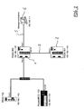
- FIG. 2 shows the network infrastructure in sections, according to FIG. 1 is available.
- the network infrastructure device 1 has the memory unit 11 and the network infrastructure device 2 is connected to it.
- other clients such. B. the RS 20-102 or the Power MICE 103 connected.
- the network infrastructure device 1 makes the local configuration data (its own and that of the network infrastructure device 2 or other network infrastructure devices) available to a higher-level network management unit 6 so as to be able to recognize and remedy errors that occur via the local configuration data of the network infrastructure devices 1, 2 and other network-wide errors can.
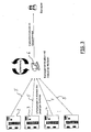
- FIG. 3 This overall error detection is in FIG. 3 shown, from which it is apparent that several network infrastructure devices 1 to 4 (possibly even more) are connected via corresponding data lines to the network management unit 6.
- Each of the network infrastructure devices 1 through 4, as in FIG. 3 are functioning as the network infrastructure device, which the functionality of the network infrastructure device 1 according to FIG. 1 takes over. It is thus possible to detect errors within a complex network topology, to prepare them in the network management unit 6 and to provide a user with error information in the overall context of the network topology. This will allow an error within the configuration of connected devices in a network infrastructure to be detected and made available to a user.
- this user can change and adjust the configuration data of the network infrastructure devices assigned to one another, so that there is no longer a deviation from one another, and this solves the problem.
- This fix can then be displayed in the network management unit which indicates to the user that the error has been corrected.
- This feedback from error detection, display to user, troubleshooting, feedback and display of troubleshooting is in FIG. 4 shown.
- the troubleshooting subsequent error correction by a user is carried out manually, or that alternatively the error detection subsequent error correction is automated.
- the troubleshooting by a user subsequent error correction has the advantage that deliberately intervened in the network infrastructure for the purpose of troubleshooting and the user also gets knowledge of errors and their rectification. It is important that the user can recognize, if at all the fixed error is actually a mistake and, if so, in what way he wants to fix it. If this is not desired, the error correction will be carried out automatically according to programmed procedures, since this can be done faster, for example, with standard errors and the user does not have to switch on. However, he can see the process displayed, so that he is only informed about an error and its automatic correction.
Description
Die Erfindung betrifft ein Verfahren zur Erkennung von Fehlkonfigurationen auf Netzwerkinfrastrukturgeräten, wobei ein jeweiliges Netzwerkinfrastrukturgerät Informationen über die eigene Konfiguration an der eigenen Netzwerkschnittstelle bereitstellt und mittels eines Discovery Protokolls diese Informationen an ein Nachbar-Netzwerkinfrastrukturgerät versendet, gemäß den Merkmalen des Oberbegriffes des Patentanspruches 1.The invention relates to a method for detecting misconfiguration on network infrastructure devices, wherein a respective network infrastructure device provides information about its own configuration at its own network interface and sends this information to a neighboring network infrastructure device by means of a discovery protocol, according to the features of the preamble of
Stand der Technik ist die Übemuittelung von Informationen zwischen Infrastrukturgeräten mittels Discovery Protokollen.The prior art is the treatment of information between infrastructure devices by means of discovery protocols.
In der
Viele moderne Infrastrukturgeräte unterstützen mindestens eine Form eines Dlscovery Protokolls wie beispielsweise das von der IEEE(Institute of Electrical and Electronics Engineers) standardisierte LLDP (Link Layer Discovery Protocol), das durch die Firma Microsoft entwickelte SSDP (Simple Service Discovery Protocol) oder das durch die Firma Cisco entwickelten CDP (Cisco Discovery Protocol), um Informationen über die eigene Konfiguration an den eigenen Netzwerkschnittstellen zu versenden. Zweck dieser Informationspakete ist die Benachrichtigung direkt verbundener Nachbargeräte über die eigene Anwesenheit und gegebenenfalls Konfiguration der eigenen Schnittstellen. Nachbargeräte sind hierbei Geräte, die mittels PDUs der Discovery Protokolle direkt erreichbar sind.Many modern infrastructure devices support at least one form of a Dlscovery protocol, such as the IEEE (IEEE) standardized LLDP (Link Layer Discovery Protocol) SSDP (Simple Service Discovery Protocol) developed by Microsoft or the Cisco Discovery Protocol (CDP) developed by Cisco to send information about its own configuration to its own network interfaces. The purpose of these information packages is to notify directly connected neighboring devices about their own presence and, if necessary, configuration of their own interfaces. Neighboring devices here are devices that are directly accessible via PDUs of the discovery protocols.
Im Nachfolgenden werden Geräte, die für den Betrieb des Netzwerks, beispielsweise als (zentrale) Vermittlungseinheit, notwendig sind, als "Geräte" oder "Infrastrukturgeräte" oder "Netzwerkinlrastrukturgeräte" bezeichnet. Beispielhaft für solche Geräte sind Ethernetswitche oder Router.In the following, devices which are necessary for the operation of the network, for example as a (central) switching unit, are referred to as "devices" or "infrastructure devices" or "network infrastructure devices". Examples of such devices are Ethernet switches or routers.
Geräte, die nicht als aktive Komponenten für den Netzbetrieb notwendig sind, sondern das zur Verfügung gestellte Netz für den Produktivbetrieb nutzen, werden nachfolgend als "Clients" bezeichnet. Beispielhaft für Clients wären Notebooks, Personal Computer oder die Steuerungseinheiten von Maschinen mit Ethernetschnittstellen.Devices that are not required as active components for network operation but use the network provided for productive operation are referred to below as "clients". Examples of clients would be notebooks, personal computers or the control units of machines with Ethernet interfaces.
Viele moderne Infrastrukturgeräte unterstützen mindestens eine Form eines Discovery Protokolls, wie zum Beispiel das von der IEEE (Institute of Electrical and Electronics Engineers) standardisierte LLDP (Link Layer Discovery Protocol) oder das proprietäre CDP (Cisco Discovery Protocol), um Informationen über die eigene Konfiguration an den eigenen Netzwerkschnittstellen zu versenden. Zweck dieser Informationspakete ist die Benachrichtigung direkt verbundener Nachbargeräte über die eigene Anwesenheit und gegebenenfalls Konfiguration der eigenen Schnittstellen.Many modern infrastructure devices support at least some form of discovery protocol, such as the IEEE (IEEE) standardized LLDP (Link Layer Discovery Protocol) or the proprietary CDP (Cisco Discovery Protocol) to provide information about their own configuration to send at their own network interfaces. The purpose of these information packages is to notify directly connected neighboring devices about their own presence and, if necessary, configuration of their own interfaces.
Der Versand der Konfigurationsdaten, sogenannte informations PDUs (Protocol Data Units), erfolgt quasi verbindungslos, d.h. jeder Switch stellt lediglich an seinen Schnittstellen seine eigenen Informations PDUs zur Verfügung, unabhängig davon, ob ein empfangendes Gerät verbunden ist oder nicht.The dispatch of the configuration data, so-called information PDUs (Protocol Data Units), takes place quasi connectionless, ie each switch provides only at its interfaces its own information PDUs, regardless of whether a receiving device is connected or not.
Unterstützen in einer Netzwerkinfrastruktur alle Geräte ein bestimmtes Discovery Protokoll, so sendet jedes Gerät die eigenen Informationen auf allen Schnittstellen, und empfängt und wertet die Informationen des direkten Nachbarn an der jeweiligen Schnittstelle aus, Ober die dieser Nachbar verbunden ist (Siehe
Weiterhin nimmt jedes Gerät die an seinen Schnittstellen empfangenen Informations PDUs vom Netz, um die Weitervermittlung an andere Infrastrukturgeräte zu verhindern, da immer nur jeweils die direkten Nachbarn eines Gerätes die jeweiligen PDUs empfangen sollen.Furthermore, each device removes the information PDUs received at its interfaces from the network in order to prevent relaying to other infrastructure devices since only the direct neighbors of a device should always receive the respective PDUs.
Die über die Informations PDUs empfangenen Daten der Nachbargeräte werden auf jedem einzelnen Gerät üblicherweise in einer Datenstruktur, der sogenannten MIB (Management Information Base) gespeichert.The data of the neighboring devices received via the information PDUs are usually stored on each individual device in a data structure, the so-called MIB (Management Information Base).
Auf diese MIB kann über eine Managerneritschnittstelle, wie z.B. das SNMP (Simple Network Management Protocol), zugegriffen und die aktuellen Nachbarinformationen ausgelesen werden.This MIB can be accessed via a manager edge interface, such as the SNMP (Simple Network Management Protocol), accessed and read the current neighbor information.
Zusätzlich zu den von den Nachbarn erhaltenen Informationen speichert jedes Gerät üblicherweise ebenfalls die Konfiguration seiner eigenen Schnittstellen in der MIB ab. Hierbei kann es je nach Konfiguration der Geräte zu Abweichungen infolge unterschiedlicher Einstellungen bei der vorgenommenen Konfiguration kommen.In addition to the information received from neighbors, each device typically also stores the configuration of its own interfaces in the MIB. Depending on the configuration of the devices, deviations may occur as a result of different settings in the configuration made.
Aufgabe dieser Erfindung ist daher die Erkennung von Fehlkonfigurationen auf NetzwerkinfrastrukturgerätenThe object of this invention is therefore the detection of misconfiguration on network infrastructure devices
Ziel der Erfindung ist die Beschreibung von Verfahren, mit denen die über Discovery Protokolle (wie z.B. LLDP) auf den Netzwerkinfrastrukturgeräten verfügbaren Nachbarinformationen für die Erkennung von Konfigurationsfehlern zwischen dem lokalen und dem entfernten Gerät genutzt werden können.The aim of the invention is to describe methods by which the neighbor information available on the network infrastructure devices via discovery protocols (such as LLDP) can be used for the detection of configuration errors between the local and the remote device.
Diese Aufgabe wird von den Merkmalen des Patentanspruches 1 gelöst.This object is solved by the features of
Erfindungsgemäß ist vorgesehen, dass die von der Speichereinheit des einen Netzwerkinfrastrukturgeräte zur Verfügung gestellten Informationen über die Nachbar-Netzwerkinfrastrukturgeräte zur Erkennung von Fehlkonfigurationen zwischen den jeweiligen Geräten durch Vergleich der in der Speichereinheit abgelegten Daten genutzt werden.According to the invention, the information provided by the storage unit of the one network infrastructure device about the neighboring network infrastructure devices is used to detect misconfiguration between the respective devices by comparing the data stored in the storage unit.
Die Erkennung von Fehlkonfigurationen erfolgt dabei wie folgt beschrieben:The detection of misconfigurations is carried out as follows:
Die von der Speichereinheit (MIB) zur Verfügung gestellten Informationen über die Nachbargeräte und die lokalen Geräte können zur Erkennung von Fehlkonfigurationen zwischen den jeweiligen Geräten genutzt werden.The information provided by the storage device (MIB) about the neighboring devices and the local devices can be used to detect misconfiguration between the respective devices.
Hierfür wird für jedes über das Discovery Protokoll erkannte Gerät die in der MIB vorhandenen Informationen für die Schnittstelle am abgefragten Gerät und die Schnittstelle am Nachbargerät ermittelt.For this purpose, for each device detected via the discovery protocol, the information available in the MIB for the interface at the device in question and the interface at the neighboring device are determined.
Nachfolgend werden die Informationen gegeneinander ausgewertet, woraus sich eine aus vielen möglichen Konstellationen der Schnittstellenkonfiguration ergibt.Subsequently, the information is evaluated against each other, resulting in one of many possible constellations of the interface configuration.
Diese Konstellation wird nachfolgend von einer Auswertelogik bewertet. Die Auswertung ermittelt, abhängig von der bestehenden Konstellation, fehlerfreie oder fehlerbehaftete Konfigurationen zwischen den zwei Geräten.This constellation is subsequently evaluated by an evaluation logic. Depending on the existing constellation, the evaluation determines faultless or faulty configurations between the two devices.
Diese Informationen können nun über eine Schnittstelle zum Endbenutzer ausgegeben werden, um diesen über das Problem in der Gerätekonfiguration zu informieren.This information can now be output via an interface to the end user to inform them about the problem in the device configuration.
Ein konkretes Beispiel wären zwei Netzwerkswitche, die über ein Twisted Pair Kupferkabel miteinander verbunden sind. Auf dem lokalen Gerät, also dem Gerät auf das z.B. über SNMP auf die MIB zugegriffen wird, ist die Netzwerkschnittstelle an der das Nachbargerät angeschlossen ist auf 100 MBit Full Duplex Automatisch konfiguriert.A concrete example would be two network switches, which are connected to each other via a twisted pair copper cable. On the local device, ie the device on the e.g. The network interface to which the neighboring device is connected is configured to 100 Mbps Full Duplex Automatically via SNMP.
Auf dem Nachbargerät ist die Netzwerkschnittstelle, an die das lokale Gerät angeschlossen ist auf 100 MBit Full Duplex Manuell konfiguriert.On the neighboring device, the network interface to which the local device is connected is configured to 100 Mbps Full Duplex Manual.
Diese Konstellation kann unter Umständen zu Problemen im Betrieb führen. Die Auswertelogik vergleicht die Informationen der lokalen Schnittstelle und der Nachbarschnittstelle und ermittelt dieses Konfigurationsproblem. Nachfolgend wird das Problem in der Administrationsoberfläche des Switches dem Benutzer gemeldet.This constellation can possibly lead to problems during operation. The evaluation logic compares the information of the local interface and the neighboring interface and determines this configuration problem. Subsequently, the problem is reported to the user in the administration interface of the switch.
Weiterhin ist eine Nutzung der lokalen Fehlererkennung für die globale Fehlererkennung möglich. Die bisher beschriebene Fehlererkennung bietet für jedes Infrastrukturgerät einzeln eine Fehlererkennung im Kontext des jeweils lokalen Gerätes.Furthermore, a use of the local error detection for the global error detection is possible. The error detection described hitherto provides individually for each infrastructure device an error detection in the context of the respective local device.
Da diese Fehlererkennung auf jedem Gerät einzeln durchgeführt werden kann, stehen für jedes Gerät jeweils lokale Fehlererkennungsdaten in der Gesamtheit der Infrastruktur zur Verfügung.Because this fault detection can be performed on each device individually, local fault detection data is available in the entirety of the infrastructure for each device.
Wenn diese jeweils lokalen Daten einer übergeordneten Instanz, z.B. einer Softwarekomponente für das Netzwerkmanagement zur Verfügung gestellt werden, so können über die lokalen Daten netzwerkübergreifende Fehler erkannt werden, wie beispielsweise über verschiedene Switche falsch konfigurierte VLANs (Virtual Local Area Networks) im Kontext des gesamten Netzwerks.If these local data are made available to a higher-level instance, eg a software component for network management, cross-network errors can be detected via the local data, such as incorrectly configured Virtual Local Area Networks (VLANs) in the context of the entire network ,
Der Einsatz der Fehlererkennung ist also nicht zwingend auf einen gerätebezogenen Kontext beschränkt, also beispielsweise die Darstellung in der Managementschnittstelle eines einzelnen Infrastrukturgerätes, sondern kann auch innerhalb einer übergeordneten Managementinstanz wie beispielsweise einer Softwarekomponente für das Netzwerkmanagement erfolgen.The use of error detection is therefore not necessarily limited to a device-related context, so for example, the representation in the management interface of a single infrastructure device, but can also be done within a higher-level management instance such as a software component for network management.
Eine Ausführung der Erfindung, auf die diese jedoch nicht beschränkt ist, ist im Folgenden erläutert und anhand der Figuren beschrieben.An embodiment of the invention, to which, however, is not limited, is explained below and described with reference to the figures.
In
Dies erfolgt beispielsweise dadurch, dass über das Discovery-Protokoll, wie beispielsweise LLDP oder ein anderes, die in der Speichereinheit 11 vorhandenen Informationen für die Schnittstelle am abgefragten Netzwerkinfrastrukturgerät 1 und die Schnittstelle am Nachbar-Netzwerkinfrastrukturgerät 2 oder 3 oder 4 ermittelt und nachfolgend die Informationen gegeneinander ausgewertet werden (wozu das jeweilige Netzwerkinfrastrukturgerät 1 die nötige Hard- und Software aufweist), woraus sich eine aus vielen möglichen Konstellationen der Schnittstellenkonfiguration ergibt. Das bedeutet, dass die einzelnen Konfigurationen der Netzwerkinfrastrukturgeräte 1 bis 4 in eine Tabelle eingetragen und verglichen werden können, wobei sich Fehlerfreiheit ergibt, wenn die über eine Datenleitung 5 miteinander verbundenen Netzwerkinfrastrukturgeräte (beispielsweise 1 mit 2 oder 1 mit 3 oder 1 mit 4 bei der Netzwerkinfrastruktur gemäss
Diese übergreifende Fehlererkennung ist in
Dabei ist denkbar, dass die der Fehlererkennung nachgehende Fehlerbehebung durch einen Benutzer, insbesondere einen Systemadministrator, manuell durchgeführt wird, oder dass alternativ die der Fehlererkennung nachgehende Fehlerbehebung automatisiert erfolgt. Die der Fehlererkennung nachgehende Fehlerbehebung durch einen Benutzer hat den Vorteil, dass bewusst in die Netzwerkinfrastruktur zwecks Fehlerbehebung eingegriffen wird und der Benutzer auch Kenntnis von Fehlern und deren Behebung bekommt. Wichtig ist dabei, dass der Benutzer erkennen kann, ob überhaupt der feststegestellte Fehler tatsächlich ein Fehler ist und, wenn ja, auf welche Art und Weise er ihn beheben will. Wird dies nicht gewünscht, erfolgt die Fehlerbehebung automatisch nach programmierten Abläufen, da dies zum Beispiel bei Standardfehlern schneller erfolgen kann und sich der Benutzer nicht einschalten muss. Er kann jedoch den Vorgang angezeigt bekommen, so dass er lediglich noch über einen Fehler und dessen automatische Behebung informiert ist.It is conceivable that the troubleshooting subsequent error correction by a user, in particular a system administrator, is carried out manually, or that alternatively the error detection subsequent error correction is automated. The troubleshooting by a user subsequent error correction has the advantage that deliberately intervened in the network infrastructure for the purpose of troubleshooting and the user also gets knowledge of errors and their rectification. It is important that the user can recognize, if at all the fixed error is actually a mistake and, if so, in what way he wants to fix it. If this is not desired, the error correction will be carried out automatically according to programmed procedures, since this can be done faster, for example, with standard errors and the user does not have to switch on. However, he can see the process displayed, so that he is only informed about an error and its automatic correction.
Claims (6)
- Method for recognizing incorrect configurations on network infrastructure devices, wherein a respective local network infrastructure device (1) provides information about its own configuration on its own network interface and uses a discovery protocol to send this information to its neighbouring network infrastructure devices (2 to 4), wherein the neighbouring network infrastructure devices (2 to 4) use the discovery protocol to transmit their configuration data to the local network infrastructure device (1), wherein also each network infrastructure device (1 to 4) takes from the network the configuration data received on its interfaces from the neighbouring network infrastructure devices in order to prevent them from being conveyed onward to other network infrastructure devices which are not neighbours in the sense of direct accessibility, wherein also the configuration data received by the local network infrastructure device (1) from the direct neighbouring network infrastructure devices (2 to 4) are stored in a memory unit on the local network infrastructure device (1) as a data structure, wherein the received data stored in the memory unit of the local network infrastructure device (1) from the direct neighbouring network infrastructure devices (2 to 4) are used for a comparison with the data from the local network infrastructure device (1).
- Method according to Claim 1, characterized in that the discovery protocol is used to ascertain the information available in the memory unit for the interface on the neighbouring network infrastructure device and the interface on the neighbouring network infrastructure device and subsequently to evaluate the pieces of information against one another, which results in one of many possible arrangements for the interface configuration.
- Method according to Claim 2, characterized in that these determined arrangements are assessed by an evaluation logic unit, wherein the evaluation, on the basis of the existing arrangement, ascertains error-free or erroneous configurations between the two devices, and this information is output to the end user via an interface in order to inform said end user about the problem in the device configuration.
- Method according to Claim 2 or 3, characterized in that the local configuration data from at least one network infrastructure device are made available to a superordinate network management unit so as to use the local configuration data to recognize cross-network errors.
- Method according to Claim 2, 3 or 4, characterized in that the error correction which succeeds the error recognition is performed manually by a user, particularly a system administrator.
- Method according to Claim 2, 3 or 4, characterized in that the error correction which succeeds the error recognition takes place automatically.
Applications Claiming Priority (1)
| Application Number | Priority Date | Filing Date | Title |
|---|---|---|---|
| DE102007039484A DE102007039484A1 (en) | 2007-08-21 | 2007-08-21 | Detection of misconfiguration on network infrastructure |
Publications (2)
| Publication Number | Publication Date |
|---|---|
| EP2028791A1 EP2028791A1 (en) | 2009-02-25 |
| EP2028791B1 true EP2028791B1 (en) | 2012-07-04 |
Family
ID=39735547
Family Applications (1)
| Application Number | Title | Priority Date | Filing Date |
|---|---|---|---|
| EP08013818A Active EP2028791B1 (en) | 2007-08-21 | 2008-08-01 | Recognition of incorrect configurations on network infrastructure devices |
Country Status (3)
| Country | Link |
|---|---|
| US (1) | US20090052328A1 (en) |
| EP (1) | EP2028791B1 (en) |
| DE (1) | DE102007039484A1 (en) |
Families Citing this family (5)
| Publication number | Priority date | Publication date | Assignee | Title |
|---|---|---|---|---|
| WO2005066169A2 (en) * | 2003-12-30 | 2005-07-21 | 3M Innovative Properties Company | Imidazoquinolinyl, imidazopyridinyl, and imidazonaphthyridinyl sulfonamides |
| US8543673B2 (en) * | 2009-04-21 | 2013-09-24 | Alcatel Lucent | Rapid provisioning of network devices using automated configuration |
| JP6537115B2 (en) * | 2016-03-30 | 2019-07-03 | Necプラットフォームズ株式会社 | Network device, configuration exchange method, maintenance exchange method, configuration exchange program, and maintenance exchange program |
| US10644947B2 (en) | 2018-09-27 | 2020-05-05 | International Business Machines Corporation | Non-invasive diagnosis of configuration errors in distributed system |
| US11586488B2 (en) | 2018-11-21 | 2023-02-21 | Cisco Technology, Inc. | Return and replacement protocol (RRP) |
Family Cites Families (7)
| Publication number | Priority date | Publication date | Assignee | Title |
|---|---|---|---|---|
| US5265241A (en) * | 1990-09-04 | 1993-11-23 | International Business Machines Corporation | Method and apparatus for verifying the configuration of a link-connected network |
| US7126964B1 (en) * | 2000-02-11 | 2006-10-24 | Microsoft Corporation | Method and apparatus for network analysis, such as analyzing and correlating identifiers of frame relay circuits in a network |
| US7228346B1 (en) * | 2000-04-21 | 2007-06-05 | Sun Microsystems, Inc. | IDL event and request formatting for corba gateway |
| US7325060B2 (en) * | 2004-03-15 | 2008-01-29 | Micrel, Inc. | Management system for hardware network devices |
| US8644820B2 (en) * | 2006-11-13 | 2014-02-04 | Samsung Electronics Co., Ltd. | Apparatus and method for acquiring service information in wireless network |
| US8140654B2 (en) * | 2007-04-27 | 2012-03-20 | Futurewei Technologies, Inc. | Verifying management virtual local area network identifier provisioning consistency |
| US8442072B2 (en) * | 2007-05-25 | 2013-05-14 | Futurewei Technologies, Inc. | Method of preventing transport leaks in hybrid switching networks by extension of the link layer discovery protocol (LLDP) |
-
2007
- 2007-08-21 DE DE102007039484A patent/DE102007039484A1/en not_active Ceased
-
2008
- 2008-08-01 EP EP08013818A patent/EP2028791B1/en active Active
- 2008-08-21 US US12/195,634 patent/US20090052328A1/en not_active Abandoned
Also Published As
| Publication number | Publication date |
|---|---|
| DE102007039484A1 (en) | 2009-02-26 |
| EP2028791A1 (en) | 2009-02-25 |
| US20090052328A1 (en) | 2009-02-26 |
Similar Documents
| Publication | Publication Date | Title |
|---|---|---|
| EP2049960B1 (en) | Method for the starting up of at least one field instrument | |
| DE102007015539B4 (en) | Method for reconfiguring a communication network | |
| DE60116178T2 (en) | Root cause analysis in a distributed network management architecture | |
| EP2693700B1 (en) | Method for message transmission in a redundant industrial communication network and communication device for a redundant industrial communication network | |
| EP2688249B1 (en) | Method for message transmission in a redundant industrial communication network and communication device for a redundant industrial communication network | |
| DE19526001A1 (en) | Automatic determination of topology of ATM networks | |
| WO2008037679A1 (en) | Method for reconfiguring a communication network | |
| EP2343857A1 (en) | Network node for a communication network | |
| EP1955480B1 (en) | Network having redundancy properties, ethernet switch for such a network, and method for configuring such a network | |
| EP2028791B1 (en) | Recognition of incorrect configurations on network infrastructure devices | |
| EP1869839B1 (en) | Method, computer program product and network node element for the rapid identification of malfunctions in transmission paths and/or in nodes | |
| DE102018213441A1 (en) | ADAPTIVE ETHERNET NETWORK REPEATER WITH AUTO-LINK-SPEED NEGOTIATION | |
| EP3628078B1 (en) | Method for operating a communication network comprising multiple communication devices of an industrial automation system and control unit | |
| EP2704370B1 (en) | Method for message transmission in a redundant industrial communication network and communication device for a redundant industrial communication network | |
| DE10305415A1 (en) | Method and device for media-redundant operation of a terminal in a network | |
| EP3092747B1 (en) | Method for incorporating a communication device in a network, and arrangement having at least one network filter component and at least one configuration server | |
| EP3787237B1 (en) | Method for data transmission in a redundantly operable communication network and coupling communication device | |
| DE102018103097B3 (en) | A topology determination method in a mobile site, a computer program, a computer program product, and a corresponding mobile site | |
| EP1803261B1 (en) | Method for error detection in a packet-based message distribution system | |
| EP2290882B1 (en) | Method for multiple error redundancy in networks with ring topologies | |
| WO2008061691A2 (en) | Method and device for the exchange of data | |
| DE102005003059B4 (en) | Method for operating a network management station | |
| EP1749369B1 (en) | Method and devices for operating a management network in the event a manager fails | |
| EP3649769B1 (en) | Method for operating a data network of a vehicle, and vehicle having a data network | |
| EP3026848A1 (en) | Method for data transmission in a redundantly operable industrial communication network and coupling communication device |
Legal Events
| Date | Code | Title | Description |
|---|---|---|---|
| PUAI | Public reference made under article 153(3) epc to a published international application that has entered the european phase |
Free format text: ORIGINAL CODE: 0009012 |
|
| AK | Designated contracting states |
Kind code of ref document: A1 Designated state(s): AT BE BG CH CY CZ DE DK EE ES FI FR GB GR HR HU IE IS IT LI LT LU LV MC MT NL NO PL PT RO SE SI SK TR |
|
| AX | Request for extension of the european patent |
Extension state: AL BA MK RS |
|
| 17P | Request for examination filed |
Effective date: 20090731 |
|
| 17Q | First examination report despatched |
Effective date: 20090826 |
|
| AKX | Designation fees paid |
Designated state(s): AT BE BG CH CY CZ DE DK EE ES FI FR GB GR HR HU IE IS IT LI LT LU LV MC MT NL NO PL PT RO SE SI SK TR |
|
| GRAP | Despatch of communication of intention to grant a patent |
Free format text: ORIGINAL CODE: EPIDOSNIGR1 |
|
| RTI1 | Title (correction) |
Free format text: RECOGNITION OF INCORRECT CONFIGURATIONS ON NETWORK INFRASTRUCTURE DEVICES |
|
| RIN1 | Information on inventor provided before grant (corrected) |
Inventor name: RENTSCHLER, MARKUS Inventor name: KLEINEBERG, OLIVER |
|
| GRAS | Grant fee paid |
Free format text: ORIGINAL CODE: EPIDOSNIGR3 |
|
| GRAA | (expected) grant |
Free format text: ORIGINAL CODE: 0009210 |
|
| AK | Designated contracting states |
Kind code of ref document: B1 Designated state(s): AT BE BG CH CY CZ DE DK EE ES FI FR GB GR HR HU IE IS IT LI LT LU LV MC MT NL NO PL PT RO SE SI SK TR |
|
| REG | Reference to a national code |
Ref country code: GB Ref legal event code: FG4D Free format text: NOT ENGLISH |
|
| REG | Reference to a national code |
Ref country code: CH Ref legal event code: EP |
|
| REG | Reference to a national code |
Ref country code: AT Ref legal event code: REF Ref document number: 565500 Country of ref document: AT Kind code of ref document: T Effective date: 20120715 |
|
| REG | Reference to a national code |
Ref country code: IE Ref legal event code: FG4D Free format text: LANGUAGE OF EP DOCUMENT: GERMAN |
|
| REG | Reference to a national code |
Ref country code: DE Ref legal event code: R096 Ref document number: 502008007637 Country of ref document: DE Effective date: 20120823 |
|
| REG | Reference to a national code |
Ref country code: NL Ref legal event code: VDEP Effective date: 20120704 |
|
| PG25 | Lapsed in a contracting state [announced via postgrant information from national office to epo] |
Ref country code: SI Free format text: LAPSE BECAUSE OF FAILURE TO SUBMIT A TRANSLATION OF THE DESCRIPTION OR TO PAY THE FEE WITHIN THE PRESCRIBED TIME-LIMIT Effective date: 20120704 |
|
| REG | Reference to a national code |
Ref country code: LT Ref legal event code: MG4D Effective date: 20120704 |
|
| PG25 | Lapsed in a contracting state [announced via postgrant information from national office to epo] |
Ref country code: NO Free format text: LAPSE BECAUSE OF FAILURE TO SUBMIT A TRANSLATION OF THE DESCRIPTION OR TO PAY THE FEE WITHIN THE PRESCRIBED TIME-LIMIT Effective date: 20121004 Ref country code: HR Free format text: LAPSE BECAUSE OF FAILURE TO SUBMIT A TRANSLATION OF THE DESCRIPTION OR TO PAY THE FEE WITHIN THE PRESCRIBED TIME-LIMIT Effective date: 20120704 Ref country code: FI Free format text: LAPSE BECAUSE OF FAILURE TO SUBMIT A TRANSLATION OF THE DESCRIPTION OR TO PAY THE FEE WITHIN THE PRESCRIBED TIME-LIMIT Effective date: 20120704 Ref country code: CY Free format text: LAPSE BECAUSE OF FAILURE TO SUBMIT A TRANSLATION OF THE DESCRIPTION OR TO PAY THE FEE WITHIN THE PRESCRIBED TIME-LIMIT Effective date: 20120704 Ref country code: IS Free format text: LAPSE BECAUSE OF FAILURE TO SUBMIT A TRANSLATION OF THE DESCRIPTION OR TO PAY THE FEE WITHIN THE PRESCRIBED TIME-LIMIT Effective date: 20121104 Ref country code: LT Free format text: LAPSE BECAUSE OF FAILURE TO SUBMIT A TRANSLATION OF THE DESCRIPTION OR TO PAY THE FEE WITHIN THE PRESCRIBED TIME-LIMIT Effective date: 20120704 |
|
| BERE | Be: lapsed |
Owner name: HIRSCHMANN AUTOMATION AND CONTROL G.M.B.H. Effective date: 20120831 |
|
| PG25 | Lapsed in a contracting state [announced via postgrant information from national office to epo] |
Ref country code: LV Free format text: LAPSE BECAUSE OF FAILURE TO SUBMIT A TRANSLATION OF THE DESCRIPTION OR TO PAY THE FEE WITHIN THE PRESCRIBED TIME-LIMIT Effective date: 20120704 Ref country code: PL Free format text: LAPSE BECAUSE OF FAILURE TO SUBMIT A TRANSLATION OF THE DESCRIPTION OR TO PAY THE FEE WITHIN THE PRESCRIBED TIME-LIMIT Effective date: 20120704 Ref country code: GR Free format text: LAPSE BECAUSE OF FAILURE TO SUBMIT A TRANSLATION OF THE DESCRIPTION OR TO PAY THE FEE WITHIN THE PRESCRIBED TIME-LIMIT Effective date: 20121005 Ref country code: SE Free format text: LAPSE BECAUSE OF FAILURE TO SUBMIT A TRANSLATION OF THE DESCRIPTION OR TO PAY THE FEE WITHIN THE PRESCRIBED TIME-LIMIT Effective date: 20120704 Ref country code: PT Free format text: LAPSE BECAUSE OF FAILURE TO SUBMIT A TRANSLATION OF THE DESCRIPTION OR TO PAY THE FEE WITHIN THE PRESCRIBED TIME-LIMIT Effective date: 20121105 |
|
| REG | Reference to a national code |
Ref country code: CH Ref legal event code: PL |
|
| PG25 | Lapsed in a contracting state [announced via postgrant information from national office to epo] |
Ref country code: MC Free format text: LAPSE BECAUSE OF NON-PAYMENT OF DUE FEES Effective date: 20120831 Ref country code: NL Free format text: LAPSE BECAUSE OF FAILURE TO SUBMIT A TRANSLATION OF THE DESCRIPTION OR TO PAY THE FEE WITHIN THE PRESCRIBED TIME-LIMIT Effective date: 20120704 |
|
| PG25 | Lapsed in a contracting state [announced via postgrant information from national office to epo] |
Ref country code: CH Free format text: LAPSE BECAUSE OF NON-PAYMENT OF DUE FEES Effective date: 20120831 Ref country code: EE Free format text: LAPSE BECAUSE OF FAILURE TO SUBMIT A TRANSLATION OF THE DESCRIPTION OR TO PAY THE FEE WITHIN THE PRESCRIBED TIME-LIMIT Effective date: 20120704 Ref country code: LI Free format text: LAPSE BECAUSE OF NON-PAYMENT OF DUE FEES Effective date: 20120831 Ref country code: RO Free format text: LAPSE BECAUSE OF FAILURE TO SUBMIT A TRANSLATION OF THE DESCRIPTION OR TO PAY THE FEE WITHIN THE PRESCRIBED TIME-LIMIT Effective date: 20120704 Ref country code: CZ Free format text: LAPSE BECAUSE OF FAILURE TO SUBMIT A TRANSLATION OF THE DESCRIPTION OR TO PAY THE FEE WITHIN THE PRESCRIBED TIME-LIMIT Effective date: 20120704 Ref country code: ES Free format text: LAPSE BECAUSE OF FAILURE TO SUBMIT A TRANSLATION OF THE DESCRIPTION OR TO PAY THE FEE WITHIN THE PRESCRIBED TIME-LIMIT Effective date: 20121015 Ref country code: DK Free format text: LAPSE BECAUSE OF FAILURE TO SUBMIT A TRANSLATION OF THE DESCRIPTION OR TO PAY THE FEE WITHIN THE PRESCRIBED TIME-LIMIT Effective date: 20120704 |
|
| PLBE | No opposition filed within time limit |
Free format text: ORIGINAL CODE: 0009261 |
|
| STAA | Information on the status of an ep patent application or granted ep patent |
Free format text: STATUS: NO OPPOSITION FILED WITHIN TIME LIMIT |
|
| REG | Reference to a national code |
Ref country code: IE Ref legal event code: MM4A |
|
| PG25 | Lapsed in a contracting state [announced via postgrant information from national office to epo] |
Ref country code: SK Free format text: LAPSE BECAUSE OF FAILURE TO SUBMIT A TRANSLATION OF THE DESCRIPTION OR TO PAY THE FEE WITHIN THE PRESCRIBED TIME-LIMIT Effective date: 20120704 Ref country code: BE Free format text: LAPSE BECAUSE OF NON-PAYMENT OF DUE FEES Effective date: 20120831 Ref country code: IT Free format text: LAPSE BECAUSE OF FAILURE TO SUBMIT A TRANSLATION OF THE DESCRIPTION OR TO PAY THE FEE WITHIN THE PRESCRIBED TIME-LIMIT Effective date: 20120704 |
|
| 26N | No opposition filed |
Effective date: 20130405 |
|
| GBPC | Gb: european patent ceased through non-payment of renewal fee |
Effective date: 20121004 |
|
| PG25 | Lapsed in a contracting state [announced via postgrant information from national office to epo] |
Ref country code: IE Free format text: LAPSE BECAUSE OF NON-PAYMENT OF DUE FEES Effective date: 20120801 Ref country code: GB Free format text: LAPSE BECAUSE OF NON-PAYMENT OF DUE FEES Effective date: 20121004 Ref country code: BG Free format text: LAPSE BECAUSE OF FAILURE TO SUBMIT A TRANSLATION OF THE DESCRIPTION OR TO PAY THE FEE WITHIN THE PRESCRIBED TIME-LIMIT Effective date: 20121004 |
|
| REG | Reference to a national code |
Ref country code: DE Ref legal event code: R097 Ref document number: 502008007637 Country of ref document: DE Effective date: 20130405 |
|
| PG25 | Lapsed in a contracting state [announced via postgrant information from national office to epo] |
Ref country code: MT Free format text: LAPSE BECAUSE OF FAILURE TO SUBMIT A TRANSLATION OF THE DESCRIPTION OR TO PAY THE FEE WITHIN THE PRESCRIBED TIME-LIMIT Effective date: 20120704 |
|
| PG25 | Lapsed in a contracting state [announced via postgrant information from national office to epo] |
Ref country code: TR Free format text: LAPSE BECAUSE OF FAILURE TO SUBMIT A TRANSLATION OF THE DESCRIPTION OR TO PAY THE FEE WITHIN THE PRESCRIBED TIME-LIMIT Effective date: 20120704 |
|
| PG25 | Lapsed in a contracting state [announced via postgrant information from national office to epo] |
Ref country code: LU Free format text: LAPSE BECAUSE OF NON-PAYMENT OF DUE FEES Effective date: 20120801 |
|
| PG25 | Lapsed in a contracting state [announced via postgrant information from national office to epo] |
Ref country code: HU Free format text: LAPSE BECAUSE OF FAILURE TO SUBMIT A TRANSLATION OF THE DESCRIPTION OR TO PAY THE FEE WITHIN THE PRESCRIBED TIME-LIMIT Effective date: 20080801 |
|
| REG | Reference to a national code |
Ref country code: AT Ref legal event code: MM01 Ref document number: 565500 Country of ref document: AT Kind code of ref document: T Effective date: 20130801 |
|
| PG25 | Lapsed in a contracting state [announced via postgrant information from national office to epo] |
Ref country code: AT Free format text: LAPSE BECAUSE OF NON-PAYMENT OF DUE FEES Effective date: 20130801 |
|
| REG | Reference to a national code |
Ref country code: FR Ref legal event code: PLFP Year of fee payment: 9 |
|
| REG | Reference to a national code |
Ref country code: FR Ref legal event code: PLFP Year of fee payment: 10 |
|
| REG | Reference to a national code |
Ref country code: FR Ref legal event code: PLFP Year of fee payment: 11 |
|
| REG | Reference to a national code |
Ref country code: DE Ref legal event code: R079 Ref document number: 502008007637 Country of ref document: DE Free format text: PREVIOUS MAIN CLASS: H04L0012240000 Ipc: H04L0041000000 |
|
| PGFP | Annual fee paid to national office [announced via postgrant information from national office to epo] |
Ref country code: FR Payment date: 20230823 Year of fee payment: 16 Ref country code: DE Payment date: 20230821 Year of fee payment: 16 |