EP2014035B1 - Ethernet vll spoke termination at an ip interface - Google Patents
Ethernet vll spoke termination at an ip interface Download PDFInfo
- Publication number
- EP2014035B1 EP2014035B1 EP07789684A EP07789684A EP2014035B1 EP 2014035 B1 EP2014035 B1 EP 2014035B1 EP 07789684 A EP07789684 A EP 07789684A EP 07789684 A EP07789684 A EP 07789684A EP 2014035 B1 EP2014035 B1 EP 2014035B1
- Authority
- EP
- European Patent Office
- Prior art keywords
- packet
- next hop
- recited
- pseudo
- wire
- Prior art date
- Legal status (The legal status is an assumption and is not a legal conclusion. Google has not performed a legal analysis and makes no representation as to the accuracy of the status listed.)
- Not-in-force
Links
- 238000000034 method Methods 0.000 claims description 45
- 238000005538 encapsulation Methods 0.000 claims description 6
- 238000004590 computer program Methods 0.000 claims 2
- 238000010586 diagram Methods 0.000 description 16
- 238000013459 approach Methods 0.000 description 14
- 230000005641 tunneling Effects 0.000 description 6
- 238000004891 communication Methods 0.000 description 5
- 230000027455 binding Effects 0.000 description 3
- 238000009739 binding Methods 0.000 description 3
- 230000006870 function Effects 0.000 description 3
- 230000005540 biological transmission Effects 0.000 description 2
- 238000010276 construction Methods 0.000 description 2
- 238000012545 processing Methods 0.000 description 2
- 230000007246 mechanism Effects 0.000 description 1
- 238000012986 modification Methods 0.000 description 1
- 230000004048 modification Effects 0.000 description 1
- 230000003287 optical effect Effects 0.000 description 1
- 230000003068 static effect Effects 0.000 description 1
- 239000004557 technical material Substances 0.000 description 1
Images


Classifications
-
- H—ELECTRICITY
- H04—ELECTRIC COMMUNICATION TECHNIQUE
- H04L—TRANSMISSION OF DIGITAL INFORMATION, e.g. TELEGRAPHIC COMMUNICATION
- H04L45/00—Routing or path finding of packets in data switching networks
-
- H—ELECTRICITY
- H04—ELECTRIC COMMUNICATION TECHNIQUE
- H04L—TRANSMISSION OF DIGITAL INFORMATION, e.g. TELEGRAPHIC COMMUNICATION
- H04L45/00—Routing or path finding of packets in data switching networks
- H04L45/50—Routing or path finding of packets in data switching networks using label swapping, e.g. multi-protocol label switch [MPLS]
-
- H—ELECTRICITY
- H04—ELECTRIC COMMUNICATION TECHNIQUE
- H04L—TRANSMISSION OF DIGITAL INFORMATION, e.g. TELEGRAPHIC COMMUNICATION
- H04L2212/00—Encapsulation of packets
Definitions
- Multi-protocol label switching (MPLS)-based virtual lease lines (VLL) and other transparent tunneling mechanisms have been provided.
- MPLS Multi-protocol label switching
- VLL virtual lease lines
- TLS transparent tunneling mechanisms
- Martini encapsulation is used to tunnel customer Ethernet frames between customer sites, through an MPLS provider backbone, in a manner that is largely transparent to the customer, in the sense that hosts at two or more sites appear to one another to be connected to and accessible via a local area network.
- MPLS tunnels known as label switched paths (LSP) are used.
- LSP label switched paths
- a VLL (sometimes referred to herein as a "pseudo-wire”) is provided in some cases by establishing a unidirectional virtual circuit in each direction between customer sites.
- An LSP may be configured to carry traffic associated with multiple virtual circuits.
- Payload data such as customer Ethernet frames
- an MPLS label stack that includes an LSP tunnel label to be used to transport the payload through the MPLS backbone and a VC label to be used at the far end, e.g., by a far end provider edge router, to associate the payload with an outbound port or other interface.
- IP connectivity it is desirable to provide IP connectivity to a remote Ethernet host/router without requiring IP inter-working, i.e., without requiring that routing decisions be made at the far end, e.g., at the far end provider edge router (e.g., ARP cache or routing table).
- the far end provider edge router e.g., ARP cache or routing table.
- any routing decisions must be made at the ingress (near) end.
- To provide IP connectivity to a remote Ethernet host/router without requiring IP inter-working therefore, it is necessary to make at the near end any routing decisions necessary to form the Ethernet (or other Layer 2) header that will be required at the far end to reach, without making an IP routing decision at that far end, the IP routing next hop for the payload (e.g., IP packet).
- the payload e.g., IP packet
- Typical prior art routers require a two step process (e.g., one to derive next hop for remote host Ethernet encapsulation and the other to determine the next hop to reach the pseudo-wire) with an external network communication between the two steps.
- a sending host sends an IP packet intended for a far end destination to a router, which adds the IP routing next hop information.
- the router sends the packet via a network interface to a separate provider edge router that adds the intermediate next hop (LSP/VC) header information and sends the packet via an interface to the LSP.
- LSP/VC intermediate next hop
- the functions of the router and provider edge router described above are integrated into a single physical system, but a separate external network communication between the separate routing processes running in the same physical system is required to perform all of the routing required to forward the packet via the pseudo-wire and have it arrive at the other end with all of the information required to route it to its destination (which may be the ultimate destination or an intermediary like a bridge or router).
- US 2002067725 discloses, in a virtual network construction method, a virtual network construction system, and a relaying apparatus within a public data communication network, control packets each having set a multicast address are multicast, and upon reception of the control packets by the relaying apparatuses belonging to the multicast address group, virtual links to the transmitting sources of the control packets are established and reply packets are returned through the virtual links, whereby the virtual links are established between all of the relaying apparatuses belonging to the multicast address group to establish the virtual network.
- US 2004017816 discloses a technique for implementing VLANs across a service provider network that involve establishing logical ports that have bindings to transport tunnels. The logical ports are then treated the same as physical ports in defining broadcast domains at particular service provider edge devices.
- Logical ports can be established for Layer 2 transport tunnels that use stacked VLAN tunneling and MPLS tunneling. Establishing a logical port that uses stacked VLAN tunneling involves binding a physical port and a stacked VLAN tunnel to the logical port. Establishing a logical port that uses MPLS tunneling involves binding an MPLS tunnel to a logical port. In one embodiment, the logical port is bound to a static MPLS tunnel and in another embodiment, the logical port is bound to a dynamic MPLS tunnel and the destination IP address of the destination service provider edge device.
- Figure 1A is a block diagram illustrating an embodiment of a provider network and associated elements.
- Figure 1B is a block diagram that represents the provider network and associated elements of Figure 1A in way that highlights the manner in which IP connectivity is provided through the MPLS backbone.
- Figure 2 is a block diagram illustrating an embodiment of a system for providing IP connectivity to a remote Ethernet host.
- Figure 3 is a block diagram illustrating an embodiment of a packet used to encapsulate and transport an Ethernet or other frame via an Ethernet pseudo-wire.
- Figure 4A is a block diagram illustrating a prior art approach to providing IP connectivity to a remote Ethernet host.
- Figure 4B is a block diagram illustrating a prior art approach to providing IP connectivity to a remote Ethernet host.
- Figure 5A is a block diagram illustrating an embodiment of an approach to providing IP connectivity to a remote Ethernet host using a single forwarding stage.
- Figure 5B is a block diagram illustrating an embodiment of an approach to providing IP connectivity to a remote Ethernet host using a single forwarding stage.
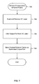
- Figure 6 is a flow chart illustrating an embodiment of a process for providing IP connectivity to a remote Ethernet host.
- Figure 7 is a flow chart illustrating an embodiment of a process for receiving via a pseudo-wire and processing an encapsulated Ethernet frame.
- the invention can be implemented in numerous ways, including as a process, an apparatus, a system, a composition of matter, a computer readable medium such as a computer readable storage medium or a computer network wherein program instructions are sent over optical or electronic communication links.
- these implementations, or any other form that the invention may take, may be referred to as techniques.
- a component such as a processor or a memory described as being configured to perform a task includes both a general component that is temporarily configured to perform the task at a given time or a specific component that is manufactured to perform the task.
- the order of the steps of disclosed processes may be altered within the scope of the invention.
- Ethernet VLL spoke termination at an IP interface is disclosed.
- the remote next hop for Ethernet encapsulation and VLL pseudo-wire dynamic next hop are determined in a single forwarding decision, made at ingress to the provider edge router, providing Ethernet pseudo-wire connectivity to a remote Ethernet attached subnet.
- An IP packet from a sending host arrives at the provider edge router at an interface associated with a routing instance.
- one or more lookups are performed to obtain all of the information required to form for the packet in a single forwarding stage both an IP next hop header and an encapsulation header (e.g., MPLS label stack including a tunnel label and a VC label associated with a pseudo-wire with which the packet is associated).
- MPLS label stack including a tunnel label and a VC label associated with a pseudo-wire with which the packet is associated.
- the far end destination host the IP address of which is the destination IP address of the packet received from the sending host, is associated with a virtual IP interface at the ingress PE, which knows to forward associated IP traffic via the LSP/pseudo-wire.
- FIG. 1A is a block diagram illustrating an embodiment of a provider network and associated elements.
- MPLS backbone 102 is used to provide IP connectivity between hosts (not shown) associated with a near end customer edge (CE) device 104 and hosts (not shown) associated with a far end customer edge device 112.
- CE near end customer edge
- LSP label switched path
- FIG. 1B is a block diagram that represents the provider network and associated elements of Figure 1A in way that highlights the manner in which IP connectivity is provided through the MPLS backbone.
- traffic received at PE 106 from CE 104 is transported via a label switched path (LSP) 120, provided in the example shown in Figures 1A and 1B by PE 106, core routers 108, and egress PE 110.
- LSP label switched path
- a virtual circuit 122 is defined to permit traffic associate with CE 104 and CE 112 to be distinguished form other traffic transported via the LSP 120.
- Martini encapsulation is used.
- An Ethernet (or other) frame desired to be delivered to a host associated with far end CE 112 is encapsulated using an MPLS label stack that includes a tunnel label associated with LSP 120 and a VC label associated with VC 122.
- PE 110 removes the VC label (the penultimate router in the MPLS backbone omits the tunnel label), associates the Ethernet frame with an outbound port based at least in part on the VC label, and sends the Ethernet frame out the identified outbound port. While communication in just one direction is shown in Figures 1A and 1B , typically two way connectivity is provided. Since an LSP is unidirectional, in the example shown connectivity from CE 112 to CE 104, e.g., would be provided by a different LSP, using a VC associated with CE 112 and CE 104.
- FIG. 2 is a block diagram illustrating an embodiment of a system for providing IP connectivity to a remote Ethernet host.
- a sending host “H1" (202) desiring to send an IP packet to a remote host “H2” (204) sends the packet via a customer edge device "CE1" (104), e.g., a switch or router located at the customer premises, to a provider edge router "PE1" (106).
- CE1 (104) is a switch and host H1 (202) determines that PE1 (106) is the IP next hop to send an IP packet to host H2 (204), sends the IP packet intended for host H2 (204) via Ethernet addressed to a MAC address associated with PE1 (106), which Ethernet frame gets switched by CE1 (104) to PE1 (106).
- CE1 (104) is a router and host H1 (202) determines that CE1 (104) is the IP next hop to send an IP packet to host H2 (204), sends the IP packet intended for host H2 (204) via Ethernet addressed to a MAC address associated with CE1 (104), which routes the IP packet to PE1 (106) (e.g., based on a determination that PE1 (106) is the IP next hop to forward from CE1 (104) an IP packet addressed to an IP address associated with host H2 (204)).
- PE1 (106) associates the received packet with a routing context, as described more fully below, and forwards the packet to PE2 (110) via Ethernet pseudo-wire 122 as an encapsulated Ethernet frame.
- PE2 (110) infers, based on a VC label included by PE1 (106) in an MPLS header used to encapsulate the Ethernet frame, an outbound port via which the Ethernet frame is to be sent, and sends the Ethernet frame via the outbound port to CE2 (112), which switches the Ethernet frame or further routes the IP packet payload of the Ethernet frame, as appropriate, to host H2 (204).
- host H2 (204) may be either the ultimate/final destination of the IP packet or an IP next hop configured to further bridge/route the IP packet to its final destination.
- Figure 3 is a block diagram illustrating an embodiment of a packet used to encapsulate and transport an Ethernet or other frame via an Ethernet pseudo-wire.
- the packet shown in Figure 3 is used to tunnel an encapsulated Ethernet packet via a pseudo-wire provided using an MPLS-based LSE; such as the pseudo-wire 122 of Figures 1 and 2 .
- MPLS label stack 304 has been added to encapsulate and original Ethernet (or other) frame 310.
- the MPLS label stack includes a tunnel label 306 that identifies an LSP to be used to tunnel the packet to a far end PE associated with a destination indicated by an inner data link control (DLC) header 312 - e.g., an Ethernet DLC header including a destination MAC address, source MAC address, Ethernet type, and/or other information - included in original Ethernet frame 310.
- Ethernet frame 310 includes a payload 314, e.g., an IP packet for which the destination MAC address indicated in inner DLC header 312 is the IP routing next hop.
- inner DLC header 312 indicates a destination MAC address associated with host H2 (204) of Figure 2 and a source MAC address associated with host H1 (202) of Figure 2 .
- MPLS label stack 304 also includes a VC label 308 that identifies a virtual circuit provisioned to tunnel through the LSP associated with tunnel label 306 traffic associated with hosts H1 (202) and H2 (204), e.g., for a customer with which the two hosts are associated.
- the VC label 308 is used at the far end PE to infer an outbound port via which to send the original Ethernet frame 310.
- the packet of Figure 3 includes an outer DLC header 302 required to send the packet via an Ethernet (or other layer 2) connection between the ingress PE (PE1 in this example) to an intermediate next hop associated with the LSP associated with the tunnel label 306, core router "P1" in this example.
- FIG 4A is a block diagram illustrating a prior art approach to providing IP connectivity to a remote Ethernet host.
- a sending host H1 (402) desiring to send an IP packet to a remote host H2 determines that its IP routing next hop for host H2 is a router R1 (404), to which it forwards the IP packet to H2 (408) via an Ethernet frame (405) addressed to router R1 in a header portion (406) of the Ethernet frame.
- the router R1 (404) determines, e.g., based on a destination IP address associated with the IP packet (408), that the host H2 is a remote host to which IP connectivity is provided via an Ethernet pseudo-wire, forms an inner Ethernet header 414 to be used at the far end to route the IP packet 408 to the IP routing next hop on the far end, and forwards the Ethernet frame to be sent to the far end (414 and 408) via an Ethernet frame (411) sent from the router R1 (404) to a provider edge router PE1 (410) associated with the remote host H2 (e.g., by virtue of being associated with an LSP tunnel and/or virtual circuit with which host H2 is associated).
- a provider edge router PE1 associated with the remote host H2 (e.g., by virtue of being associated with an LSP tunnel and/or virtual circuit with which host H2 is associated).
- the provider edge router PE1 (410) associates the received Ethernet frame with an LSP tunnel/VC, e.g., based on the physical interface (port) on which it was received, and encapsulates the Ethernet frame desired to be sent to the far end (sometimes referred to herein as the "original" Ethernet frame) (414 and 408) to form a packet 416 that includes an MPLS label stack (420) that identifies the LSP tunnel and VC circuit via which the packet is to be sent and an outer Ethernet header (422) to send the packet by Ethernet from the provider edge router PE1 (410) to a first hop core router P1 (not shown in Figure 4A ) along the LSP tunnel.
- an MPLS label stack 420
- an outer Ethernet header (422) to send the packet by Ethernet from the provider edge router PE1 (410) to a first hop core router P1 (not shown in Figure 4A ) along the LSP tunnel.
- the approach illustrated in Figure 4A requires a separate router R1 to determine the IP routing next hop information that will be required to process the frame at the far end, and a network transmission from the router R1 to the provider edge router PE1, which determines the intermediate (tunnel/VC) next hop information.
- FIG. 4B is a block diagram illustrating a prior art approach to providing IP connectivity to a remote Ethernet host.
- the functions of the router R1 (404) have been incorporated into the provider edge router PE1 (410) in the form of an IP next hop routing process (440) running on the provider edge router PE1 (410), eliminating the need for a separate system to perform the functions of router R1 (404) as described above.
- an external network connection (442) between the IP next hop routing process (440) and an intermediate next hop routing process (444) running on the same system (i.e., PE1) is still required to enable the IP next hop routing process (440) to send the Ethernet frame (411) to the intermediate next hop routing process (444) in a manner that enables the intermediate next hop.routing process (444) to associate the frame (411) with the correct routing context (e.g., to identify the tunnel/VC via which the original Ethernet frame is to be transported.
- FIG. 5A is a block diagram illustrating an embodiment of an approach to providing IP connectivity to a remote Ethernet host using a single forwarding stage.
- the IP routing next hop and the intermediate (tunnel/VC) next hop information are determined in a single forwarding stage, eliminating the need for a separate external network connection and transmission between an IP routing system/process and the system/process (e.g., PE) that determines the intermediate next hop for transport via the MPLS (or other) backbone.
- an IP routing system/process e.g., PE
- the system/process e.g., PE
- sending host H1 forwards an IP packet (512) addressed to a remote Ethernet host H2 to a provider edge router PE1 (506) via an Ethernet frame (508, having an Ethernet header 510) sent to PE1 (506), in this example via a switch (504).
- the packet 508 is sent by host H1 (502) via the switch (504) to an IP interface 514 at provider edge router PE1 (506).
- the provider edge router (506) associates the packet (508) with a routing context (516) based at least in part on the interface (514) via which the packet (508) arrived at the provider edge router.
- the routing context (518) is provided at least in part by configuring a virtual IP interface (518) and associating IP interface (514) with the virtual IP interface (518).
- the routing context (516) comprises one or more routing processes and associated data (e.g., forwarding information bases, routing tables, etc.).
- the routing context (516) is configured to determine in a single forwarding stage, based at least in part on IP header information contained in a received IP packet that has been associated with the routing context (516), such as packet (508) in the example shown, both the IP routing next hop information that will be required to deliver the IP packet to its next hop at the far end without requiring that an IP routing decision be made at the far end and the intermediate next hop information required to tunnel the packet to the far end via an associated pseudo-wire.
- the provider edge router PE1 (506) uses the IP next hop routing information to form the inner Ethernet header (524) of outbound packet (522) and the intermediate next hop routing information to form label stark (526) and outer Ethernet header (528) of outbound packet (522), which the provider edge router PE1 (506) send to the LSP tunnel/VC next hop (provider core router P1 in this example, not shown in Figure 5A ) via an interface (520).
- FIG. 5B is a block diagram illustrating an embodiment of an approach to providing IP connectivity to a remote Ethernet host using a single forwarding stage.
- the routing context (516) of Figure 5A comprises a private routing context (516) configured to determine the IP next hop information required to route the packet at the far end.
- the packet received at IP interface (514) is associated within private routing context (516) with virtual IP interface (518).
- the packet is determined to be is associated with a VLL (544) within a global routing context (540), which determines the intermediate next hop information for the outer Ethernet header (528) and MPLS label stack (526) portions of outbound packet (522) required to send the frame to the far end via interface (520) and the associated pseudo-wire.
- Figure 6 is a flow chart illustrating an embodiment of a process for providing IP connectivity to a remote Ethernet host.
- the process of Figure 6 is implemented by an ingress provider edge router such as PE1 (506) of Figure 5 .
- An IP packet is received at an IP interface (602).
- the packet is associated with a routing context (604).
- the packet is associated with a routing context based at least in part on the physical and/or logical interface at which it was received.
- An IP routing next hop information is determined and used to form an inner Ethernet header required to enable a far end provider edge router (i.e., one at the other end of a tunnel from the ingress PE to the far end PE) and/or other elements at the far end to deliver the IP packet to its IP routing next hop on the far end without making at the far end an IP routing decision for the packet (606).
- Intermediate next hop information required to forward the packet to the far end via an associated Ethernet pseudo-wire is determined and used to form an MPLS (or other) label stack (e.g., 526 of Figure 5 ) and outer Ethernet header (e.g., 528 of Figure 5 ).
- the packet formed (606 and 608) is sent to the intermediate next hop (e.g., a next hop provider core router, such as P1 in the example shown in Figures 1A and 5 ) via an interface associated with the LSP/tunnel used to provide the pseudo-wire.
- the process of Figure 6 comprises a single forwarding stage provided and performed at a provider edge router.
- different information sources e.g., forwarding/routing tables
- forwarding/routing tables are used to determine the IP routing next hop and intermediate (tunne!/VC) next hop, respectively, but the determinations are made as part of a single forward process, within one physical system, and without requiring two separate routing systems and/or processes to communicate via an external network connection.
- Figure 7 is a flow chart illustrating an embodiment of a process for receiving via a pseudo-wire and processing an encapsulated Ethernet frame.
- the process of Figure 7 is implemented by a far end (egress) provider edge router, such as PE2 in the example shown in Figures 1A-2 .
- An encapsulated Ethernet frame is received (702).
- a VC label included in a label stack used to encapsulate the received frame in read and removed (704).
- An output port via which the original Ethernet frame encapsulated within the encapsulated Ethernet frame is inferred based at least in part on the VC label (706).
- the original Ethernet frame is sent via the output port inferred at 706 (708).
- the original Ethernet frame includes an inner Ethernet header, such as inner Ethernet header 524 of Figure 5 , that enables the original Ethernet frame to be received and processed at an IP routing next hop for an IP packet that comprises the payload of the original Ethernet frame, without an IP routing decision being made at the end at which the encapsulate Ethernet frame was received at 702.
- inner Ethernet header such as inner Ethernet header 524 of Figure 5
Landscapes
- Engineering & Computer Science (AREA)
- Computer Networks & Wireless Communication (AREA)
- Signal Processing (AREA)
- Data Exchanges In Wide-Area Networks (AREA)
Abstract
Description
- Multi-protocol label switching (MPLS)-based virtual lease lines (VLL) and other transparent tunneling mechanisms (e.g., TLS) have been provided. In some implementations, Martini encapsulation is used to tunnel customer Ethernet frames between customer sites, through an MPLS provider backbone, in a manner that is largely transparent to the customer, in the sense that hosts at two or more sites appear to one another to be connected to and accessible via a local area network. Topically, MPLS tunnels known as label switched paths (LSP) are used. A VLL (sometimes referred to herein as a "pseudo-wire") is provided in some cases by establishing a unidirectional virtual circuit in each direction between customer sites. An LSP may be configured to carry traffic associated with multiple virtual circuits. Payload data, such as customer Ethernet frames, is encapsulated in part by adding to the payload an MPLS label stack that includes an LSP tunnel label to be used to transport the payload through the MPLS backbone and a VC label to be used at the far end, e.g., by a far end provider edge router, to associate the payload with an outbound port or other interface.
- It is desirable to provide IP connectivity to a remote Ethernet host/router without requiring IP inter-working, i.e., without requiring that routing decisions be made at the far end, e.g., at the far end provider edge router (e.g., ARP cache or routing table). To achieve this goal, any routing decisions must be made at the ingress (near) end. To provide IP connectivity to a remote Ethernet host/router without requiring IP inter-working, therefore, it is necessary to make at the near end any routing decisions necessary to form the Ethernet (or other Layer 2) header that will be required at the far end to reach, without making an IP routing decision at that far end, the IP routing next hop for the payload (e.g., IP packet). Typical prior art routers require a two step process (e.g., one to derive next hop for remote host Ethernet encapsulation and the other to determine the next hop to reach the pseudo-wire) with an external network communication between the two steps. In one approach, a sending host sends an IP packet intended for a far end destination to a router, which adds the IP routing next hop information. The router sends the packet via a network interface to a separate provider edge router that adds the intermediate next hop (LSP/VC) header information and sends the packet via an interface to the LSP. In another approach, the functions of the router and provider edge router described above are integrated into a single physical system, but a separate external network communication between the separate routing processes running in the same physical system is required to perform all of the routing required to forward the packet via the pseudo-wire and have it arrive at the other end with all of the information required to route it to its destination (which may be the ultimate destination or an intermediary like a bridge or router).
-
US 2002067725 discloses, in a virtual network construction method, a virtual network construction system, and a relaying apparatus within a public data communication network, control packets each having set a multicast address are multicast, and upon reception of the control packets by the relaying apparatuses belonging to the multicast address group, virtual links to the transmitting sources of the control packets are established and reply packets are returned through the virtual links, whereby the virtual links are established between all of the relaying apparatuses belonging to the multicast address group to establish the virtual network. -
US 2004017816 discloses a technique for implementing VLANs across a service provider network that involve establishing logical ports that have bindings to transport tunnels. The logical ports are then treated the same as physical ports in defining broadcast domains at particular service provider edge devices. Logical ports can be established for Layer 2 transport tunnels that use stacked VLAN tunneling and MPLS tunneling. Establishing a logical port that uses stacked VLAN tunneling involves binding a physical port and a stacked VLAN tunnel to the logical port. Establishing a logical port that uses MPLS tunneling involves binding an MPLS tunnel to a logical port. In one embodiment, the logical port is bound to a static MPLS tunnel and in another embodiment, the logical port is bound to a dynamic MPLS tunnel and the destination IP address of the destination service provider edge device. - Therefore, a way is needed to provide IP connectivity to a remote Ethernet host/router across an Ethernet pseudo-wire without requiring IP inter-working on the far end device and in a in a single forwarding stage while allowing the pseudo-wire to dynamically converge its immediate next hop.
- Various embodiments of the invention are disclosed in the following detailed description and the accompanying drawings.
-
Figure 1A is a block diagram illustrating an embodiment of a provider network and associated elements. -
Figure 1B is a block diagram that represents the provider network and associated elements ofFigure 1A in way that highlights the manner in which IP connectivity is provided through the MPLS backbone. -
Figure 2 is a block diagram illustrating an embodiment of a system for providing IP connectivity to a remote Ethernet host. -
Figure 3 is a block diagram illustrating an embodiment of a packet used to encapsulate and transport an Ethernet or other frame via an Ethernet pseudo-wire. -
Figure 4A is a block diagram illustrating a prior art approach to providing IP connectivity to a remote Ethernet host. -
Figure 4B is a block diagram illustrating a prior art approach to providing IP connectivity to a remote Ethernet host. -
Figure 5A is a block diagram illustrating an embodiment of an approach to providing IP connectivity to a remote Ethernet host using a single forwarding stage. -
Figure 5B is a block diagram illustrating an embodiment of an approach to providing IP connectivity to a remote Ethernet host using a single forwarding stage. -
Figure 6 is a flow chart illustrating an embodiment of a process for providing IP connectivity to a remote Ethernet host. -
Figure 7 is a flow chart illustrating an embodiment of a process for receiving via a pseudo-wire and processing an encapsulated Ethernet frame. - The invention can be implemented in numerous ways, including as a process, an apparatus, a system, a composition of matter, a computer readable medium such as a computer readable storage medium or a computer network wherein program instructions are sent over optical or electronic communication links. In this specification, these implementations, or any other form that the invention may take, may be referred to as techniques. A component such as a processor or a memory described as being configured to perform a task includes both a general component that is temporarily configured to perform the task at a given time or a specific component that is manufactured to perform the task. In general, the order of the steps of disclosed processes may be altered within the scope of the invention.
- A detailed description of one or more embodiments of the invention is provided below along with accompanying figures that illustrate the principles of the invention. The invention is described in connection with such embodiments, but the invention is not limited to any embodiment. The scope of the invention is limited only by the claims and the invention encompasses numerous alternatives, modifications and equivalents. Numerous specific details are set forth in the following description in order to provide a thorough understanding of the invention. These details are provided for the purpose of example and the invention may be practiced according to the claims without some or all of these specific details. For the purpose of clarity, technical material that is known in the technical fields related to the invention has not been described in detail so that the invention is not unnecessarily obscured.
- Ethernet VLL spoke termination at an IP interface is disclosed. In some embodiments, the remote next hop for Ethernet encapsulation and VLL pseudo-wire dynamic next hop are determined in a single forwarding decision, made at ingress to the provider edge router, providing Ethernet pseudo-wire connectivity to a remote Ethernet attached subnet. An IP packet from a sending host arrives at the provider edge router at an interface associated with a routing instance. At egress, one or more lookups are performed to obtain all of the information required to form for the packet in a single forwarding stage both an IP next hop header and an encapsulation header (e.g., MPLS label stack including a tunnel label and a VC label associated with a pseudo-wire with which the packet is associated). In some embodiments, the far end destination host, the IP address of which is the destination IP address of the packet received from the sending host, is associated with a virtual IP interface at the ingress PE, which knows to forward associated IP traffic via the LSP/pseudo-wire.
-
Figure 1A is a block diagram illustrating an embodiment of a provider network and associated elements. In the example shown,MPLS backbone 102 is used to provide IP connectivity between hosts (not shown) associated with a near end customer edge (CE)device 104 and hosts (not shown) associated with a far endcustomer edge device 112. In the example shown, IP traffic from hosts associated withCE 104, labeled "CE1" inFigure 1 , to hosts associated withCE 112, labeled "CE2", is tunneled throughMPLS backbone 102 through a label switched path (LSP) provided by near end provider edge (PE)router 106, labeled "PE1" inFigure 1 ,core provider routers 108, labeled "Pl", "P2", and "P3" inFigure 1 , and a far end (egress) provideredge router PE 110, labeled "PE2". -
Figure 1B is a block diagram that represents the provider network and associated elements ofFigure 1A in way that highlights the manner in which IP connectivity is provided through the MPLS backbone. As shown inFigure 1B , traffic received atPE 106 fromCE 104 is transported via a label switched path (LSP) 120, provided in the example shown inFigures 1A and 1B byPE 106,core routers 108, andegress PE 110. Avirtual circuit 122 is defined to permit traffic associate withCE 104 and CE 112 to be distinguished form other traffic transported via theLSP 120. In some embodiments, Martini encapsulation is used. An Ethernet (or other) frame desired to be delivered to a host associated withfar end CE 112, e.g., an Ethernet frame having an IP packet as its payload for which the Ethernet destination host is the IP routing next hop, is encapsulated using an MPLS label stack that includes a tunnel label associated withLSP 120 and a VC label associated with VC 122. On receipt at the far end, PE 110 removes the VC label (the penultimate router in the MPLS backbone omits the tunnel label), associates the Ethernet frame with an outbound port based at least in part on the VC label, and sends the Ethernet frame out the identified outbound port. While communication in just one direction is shown inFigures 1A and 1B , typically two way connectivity is provided. Since an LSP is unidirectional, in the example shown connectivity fromCE 112 toCE 104, e.g., would be provided by a different LSP, using a VC associated withCE 112 andCE 104. -
Figure 2 is a block diagram illustrating an embodiment of a system for providing IP connectivity to a remote Ethernet host. A sending host "H1" (202) desiring to send an IP packet to a remote host "H2" (204) sends the packet via a customer edge device "CE1" (104), e.g., a switch or router located at the customer premises, to a provider edge router "PE1" (106). In some embodiments, CE1 (104) is a switch and host H1 (202) determines that PE1 (106) is the IP next hop to send an IP packet to host H2 (204), sends the IP packet intended for host H2 (204) via Ethernet addressed to a MAC address associated with PE1 (106), which Ethernet frame gets switched by CE1 (104) to PE1 (106). In some embodiments, CE1 (104) is a router and host H1 (202) determines that CE1 (104) is the IP next hop to send an IP packet to host H2 (204), sends the IP packet intended for host H2 (204) via Ethernet addressed to a MAC address associated with CE1 (104), which routes the IP packet to PE1 (106) (e.g., based on a determination that PE1 (106) is the IP next hop to forward from CE1 (104) an IP packet addressed to an IP address associated with host H2 (204)). PE1 (106) associates the received packet with a routing context, as described more fully below, and forwards the packet to PE2 (110) viaEthernet pseudo-wire 122 as an encapsulated Ethernet frame. PE2 (110) infers, based on a VC label included by PE1 (106) in an MPLS header used to encapsulate the Ethernet frame, an outbound port via which the Ethernet frame is to be sent, and sends the Ethernet frame via the outbound port to CE2 (112), which switches the Ethernet frame or further routes the IP packet payload of the Ethernet frame, as appropriate, to host H2 (204). Note that host H2 (204) may be either the ultimate/final destination of the IP packet or an IP next hop configured to further bridge/route the IP packet to its final destination. -
Figure 3 is a block diagram illustrating an embodiment of a packet used to encapsulate and transport an Ethernet or other frame via an Ethernet pseudo-wire. In some embodiments, the packet shown inFigure 3 is used to tunnel an encapsulated Ethernet packet via a pseudo-wire provided using an MPLS-based LSE; such as the pseudo-wire 122 ofFigures 1 and2 . In the example shown, andMPLS label stack 304 has been added to encapsulate and original Ethernet (or other)frame 310. The MPLS label stack includes atunnel label 306 that identifies an LSP to be used to tunnel the packet to a far end PE associated with a destination indicated by an inner data link control (DLC) header 312 - e.g., an Ethernet DLC header including a destination MAC address, source MAC address, Ethernet type, and/or other information - included inoriginal Ethernet frame 310.Ethernet frame 310 includes apayload 314, e.g., an IP packet for which the destination MAC address indicated ininner DLC header 312 is the IP routing next hop. In the example shown,inner DLC header 312 indicates a destination MAC address associated with host H2 (204) ofFigure 2 and a source MAC address associated with host H1 (202) ofFigure 2 .MPLS label stack 304 also includes aVC label 308 that identifies a virtual circuit provisioned to tunnel through the LSP associated withtunnel label 306 traffic associated with hosts H1 (202) and H2 (204), e.g., for a customer with which the two hosts are associated. As described above, in some embodiments theVC label 308 is used at the far end PE to infer an outbound port via which to send theoriginal Ethernet frame 310. Finally, the packet ofFigure 3 includes anouter DLC header 302 required to send the packet via an Ethernet (or other layer 2) connection between the ingress PE (PE1 in this example) to an intermediate next hop associated with the LSP associated with thetunnel label 306, core router "P1" in this example. Forming theinner DLC header 312 and the intermediate next hop header portions, in this example MPLS (or other tunneling)label stack 304 andouter DLC header 302, in a single forwarding process at PE ingress, as described more fully below in connection withFigures 5-7 , is disclosed. -
Figure 4A is a block diagram illustrating a prior art approach to providing IP connectivity to a remote Ethernet host. A sending host H1 (402) desiring to send an IP packet to a remote host H2 (not shown inFigure 4A , see, e.g.,Figure 2 ) determines that its IP routing next hop for host H2 is a router R1 (404), to which it forwards the IP packet to H2 (408) via an Ethernet frame (405) addressed to router R1 in a header portion (406) of the Ethernet frame. The router R1 (404) determines, e.g., based on a destination IP address associated with the IP packet (408), that the host H2 is a remote host to which IP connectivity is provided via an Ethernet pseudo-wire, forms aninner Ethernet header 414 to be used at the far end to route theIP packet 408 to the IP routing next hop on the far end, and forwards the Ethernet frame to be sent to the far end (414 and 408) via an Ethernet frame (411) sent from the router R1 (404) to a provider edge router PE1 (410) associated with the remote host H2 (e.g., by virtue of being associated with an LSP tunnel and/or virtual circuit with which host H2 is associated). The provider edge router PE1 (410) associates the received Ethernet frame with an LSP tunnel/VC, e.g., based on the physical interface (port) on which it was received, and encapsulates the Ethernet frame desired to be sent to the far end (sometimes referred to herein as the "original" Ethernet frame) (414 and 408) to form apacket 416 that includes an MPLS label stack (420) that identifies the LSP tunnel and VC circuit via which the packet is to be sent and an outer Ethernet header (422) to send the packet by Ethernet from the provider edge router PE1 (410) to a first hop core router P1 (not shown inFigure 4A ) along the LSP tunnel. As one can see fromFigure 4A and the above description, the approach illustrated inFigure 4A requires a separate router R1 to determine the IP routing next hop information that will be required to process the frame at the far end, and a network transmission from the router R1 to the provider edge router PE1, which determines the intermediate (tunnel/VC) next hop information. -
Figure 4B is a block diagram illustrating a prior art approach to providing IP connectivity to a remote Ethernet host. In the approach shown inFigure 4B , the functions of the router R1 (404) have been incorporated into the provider edge router PE1 (410) in the form of an IP next hop routing process (440) running on the provider edge router PE1 (410), eliminating the need for a separate system to perform the functions of router R1 (404) as described above. However, an external network connection (442) between the IP next hop routing process (440) and an intermediate next hop routing process (444) running on the same system (i.e., PE1) is still required to enable the IP next hop routing process (440) to send the Ethernet frame (411) to the intermediate next hop routing process (444) in a manner that enables the intermediate next hop.routing process (444) to associate the frame (411) with the correct routing context (e.g., to identify the tunnel/VC via which the original Ethernet frame is to be transported. -
Figure 5A is a block diagram illustrating an embodiment of an approach to providing IP connectivity to a remote Ethernet host using a single forwarding stage. In the approach illustrated inFigure 5 , the IP routing next hop and the intermediate (tunnel/VC) next hop information are determined in a single forwarding stage, eliminating the need for a separate external network connection and transmission between an IP routing system/process and the system/process (e.g., PE) that determines the intermediate next hop for transport via the MPLS (or other) backbone. In the example shown, sending host H1 (502) forwards an IP packet (512) addressed to a remote Ethernet host H2 to a provider edge router PE1 (506) via an Ethernet frame (508, having an Ethernet header 510) sent to PE1 (506), in this example via a switch (504). In the example shown, thepacket 508 is sent by host H1 (502) via the switch (504) to anIP interface 514 at provider edge router PE1 (506). The provider edge router (506) associates the packet (508) with a routing context (516) based at least in part on the interface (514) via which the packet (508) arrived at the provider edge router. The routing context (518) is provided at least in part by configuring a virtual IP interface (518) and associating IP interface (514) with the virtual IP interface (518). In some embodiments, the routing context (516) comprises one or more routing processes and associated data (e.g., forwarding information bases, routing tables, etc.). In this example, the routing context (516) is configured to determine in a single forwarding stage, based at least in part on IP header information contained in a received IP packet that has been associated with the routing context (516), such as packet (508) in the example shown, both the IP routing next hop information that will be required to deliver the IP packet to its next hop at the far end without requiring that an IP routing decision be made at the far end and the intermediate next hop information required to tunnel the packet to the far end via an associated pseudo-wire. In the example shown, the provider edge router PE1 (506) uses the IP next hop routing information to form the inner Ethernet header (524) of outbound packet (522) and the intermediate next hop routing information to form label stark (526) and outer Ethernet header (528) of outbound packet (522), which the provider edge router PE1 (506) send to the LSP tunnel/VC next hop (provider core router P1 in this example, not shown inFigure 5A ) via an interface (520). -
Figure 5B is a block diagram illustrating an embodiment of an approach to providing IP connectivity to a remote Ethernet host using a single forwarding stage. In this example, the routing context (516) ofFigure 5A comprises a private routing context (516) configured to determine the IP next hop information required to route the packet at the far end. The packet received at IP interface (514) is associated within private routing context (516) with virtual IP interface (518). The packet is determined to be is associated with a VLL (544) within a global routing context (540), which determines the intermediate next hop information for the outer Ethernet header (528) and MPLS label stack (526) portions of outbound packet (522) required to send the frame to the far end via interface (520) and the associated pseudo-wire. -
Figure 6 is a flow chart illustrating an embodiment of a process for providing IP connectivity to a remote Ethernet host. In some embodiments, the process ofFigure 6 is implemented by an ingress provider edge router such as PE1 (506) ofFigure 5 . An IP packet is received at an IP interface (602). The packet is associated with a routing context (604). In some embodiments, the packet is associated with a routing context based at least in part on the physical and/or logical interface at which it was received. An IP routing next hop information is determined and used to form an inner Ethernet header required to enable a far end provider edge router (i.e., one at the other end of a tunnel from the ingress PE to the far end PE) and/or other elements at the far end to deliver the IP packet to its IP routing next hop on the far end without making at the far end an IP routing decision for the packet (606). Intermediate next hop information required to forward the packet to the far end via an associated Ethernet pseudo-wire is determined and used to form an MPLS (or other) label stack (e.g., 526 ofFigure 5 ) and outer Ethernet header (e.g., 528 ofFigure 5 ). The packet formed (606 and 608) is sent to the intermediate next hop (e.g., a next hop provider core router, such as P1 in the example shown inFigures 1A and5 ) via an interface associated with the LSP/tunnel used to provide the pseudo-wire. In some embodiments, the process ofFigure 6 comprises a single forwarding stage provided and performed at a provider edge router. In some embodiments, different information sources (e.g., forwarding/routing tables) are used to determine the IP routing next hop and intermediate (tunne!/VC) next hop, respectively, but the determinations are made as part of a single forward process, within one physical system, and without requiring two separate routing systems and/or processes to communicate via an external network connection. -
Figure 7 is a flow chart illustrating an embodiment of a process for receiving via a pseudo-wire and processing an encapsulated Ethernet frame. In some embodiments, the process ofFigure 7 is implemented by a far end (egress) provider edge router, such as PE2 in the example shown inFigures 1A-2 . An encapsulated Ethernet frame is received (702). A VC label included in a label stack used to encapsulate the received frame in read and removed (704). An output port via which the original Ethernet frame encapsulated within the encapsulated Ethernet frame is inferred based at least in part on the VC label (706). The original Ethernet frame is sent via the output port inferred at 706 (708). In some embodiments, the original Ethernet frame includes an inner Ethernet header, such asinner Ethernet header 524 ofFigure 5 , that enables the original Ethernet frame to be received and processed at an IP routing next hop for an IP packet that comprises the payload of the original Ethernet frame, without an IP routing decision being made at the end at which the encapsulate Ethernet frame was received at 702. - While a number of the examples and embodiments described herein refer to providing IP connectivity to a remote Ethernet host, the approaches disclosed herein may be used to provide connectivity to remote host using any compatible network and/or physical layer protocols.
- Although the foregoing embodiments have been described in some detail for purposes of clarity of understanding, the invention is not limited to the details provided. There are many alternative ways of implementing the invention. The disclosed embodiments are illustrative and not restrictive.
Claims (21)
- A method of providing connectivity to a remote host (204), characterized in that it comprises:receiving (602) at an interface a packet including an address associated with a remote host (204);determining (604, 606) in a single forwarding stage, based at least in part on the interface and the address, a routing next hop information required to route the packet to the remote host (204) at a far end (112) of a pseudo-wire (122) via which connectivity to the remote host (204) is provided and an intermediate next hop information required to send the packet to the far end (112) via the pseudo-wire, said pseudo-wire being a virtual lease line provided by establishing a unidirectional virtual circuit in each direction.
- A method as recited in claim 1, wherein the packet comprises an IP packet.
- A method as recited in claim 1, wherein the address comprises an IP addressed associated with the remote host (204).
- A method as recited in claim 1, wherein the routing next hop information comprises an IP routing next hop information.
- A method as recited in claim 4, further comprising using the IP routing next hop information to form a header required to provide the packet to the remote host (204) at the far end (112) of the pseudo-wire (122) without making at the far end an IP routing decision based on the address.
- A method as recited in claim 1, wherein the interface comprises an IP interface.
- A method as recited in claim 1, wherein the packet is received from a customer equipment associated with a customer with which a sending host (202) that sent the packet is associated.
- A method as recited in claim 1, wherein the pseudo-wire (122) comprises an Ethernet pseudo-wire.
- A method as recited in claim 1, wherein the pseudo-wire (122) comprises a virtual circuit.
- A method as recited in claim 9, wherein the intermediate next hop information includes a virtual circuit information associated with the virtual circuit.
- A method as recited in claim 9, wherein the virtual circuit is associated with a label switched path (LSP) (120).
- A method as recited in claim 11, wherein intermediate next hop information includes a tunnel label associated with the LSP (120).
- A method as recited in claim 11, wherein the LSP (120) comprises a tunnel through an MPLS backbone (102).
- A method as recited in claim 13, further comprising forming a label stack based at least in part on the intermediate next hop information.
- A method as recited in claim 14, wherein the label stack includes the tunnel label.
- A method as recited in claim 14, wherein the virtual circuit information comprises a virtual circuit label and the label stack includes the virtual circuit label.
- A method as recited in claim 1, wherein the remote host (204) comprises a remote Ethernet host.
- A method as recited in claim 1, wherein the intermediate next hop information includes information required to form a data link control layer header required to send the packet to an intermediate next hop associated with the pseudo-wire (122).
- A method as recited in claim 1, further comprising using the routing next hop information and the intermediate next hop information to form an outbound packet comprising an encapsulation of an Ethernet frame of which the received packet comprises the payload.
- A provider edge device, characterized in that it comprises:an interface configured to receive a packet including an address associated with a remote host (204); anda processor coupled to the interface and configured to determine in a single forwarding stage, based at least in part on the interface and the address, a routing next hop information required to route the packet to the remote host (204) at a far end (112) of a pseudo-wire (122) via which connectivity to the remote host (204) is provided and an intermediate next hop information required to send the packet to the far end (112) via the pseudo-wire, said pseudo-wire being a virtual lease line provided by establishing a unidirectional virtual circuit in each direction.
- A computer program product for providing connectivity to a remote host (204), the computer program product being embodied in a computer readable medium and characterized in that it comprises computer instructions for:receiving (602) at an interface a packet including an address associated with a remote host (204);determining (604, 606) in a single forwarding stage, based at least in part on the interface and the address, a routing next hop information required to route the packet to the remote host (204) at a far end (112) of a pseudo-wire (122) via which connectivity to the remote host (204) is provided and an intermediate next hop information required to send the packet to the far end (112) via the pseudo-wire (122), said pseudo-wire being a virtual lease line provided by establishing a unidirectional virtual circuit in each direction.
Applications Claiming Priority (2)
| Application Number | Priority Date | Filing Date | Title |
|---|---|---|---|
| US11/414,726 US7613188B1 (en) | 2006-04-27 | 2006-04-27 | Ethernet VLL spoke termination at an IP interface |
| PCT/IB2007/002539 WO2007125433A2 (en) | 2006-04-27 | 2007-04-27 | Ethernet vll spoke termination at an ip interface |
Publications (2)
| Publication Number | Publication Date |
|---|---|
| EP2014035A2 EP2014035A2 (en) | 2009-01-14 |
| EP2014035B1 true EP2014035B1 (en) | 2011-10-19 |
Family
ID=38655887
Family Applications (1)
| Application Number | Title | Priority Date | Filing Date |
|---|---|---|---|
| EP07789684A Not-in-force EP2014035B1 (en) | 2006-04-27 | 2007-04-27 | Ethernet vll spoke termination at an ip interface |
Country Status (5)
| Country | Link |
|---|---|
| US (1) | US7613188B1 (en) |
| EP (1) | EP2014035B1 (en) |
| CN (1) | CN101433030B (en) |
| AT (1) | ATE529989T1 (en) |
| WO (1) | WO2007125433A2 (en) |
Families Citing this family (16)
| Publication number | Priority date | Publication date | Assignee | Title |
|---|---|---|---|---|
| US8555352B2 (en) * | 2003-06-20 | 2013-10-08 | Juniper Networks, Inc. | Controlling access nodes with network transport devices within wireless mobile networks |
| US7746799B2 (en) * | 2003-06-20 | 2010-06-29 | Juniper Networks, Inc. | Controlling data link layer elements with network layer elements |
| US20060182113A1 (en) * | 2005-02-17 | 2006-08-17 | Lucent Technologies Inc. | Automatic discovery of pseudo-wire peer addresses in ethernet-based networks |
| US8085791B1 (en) | 2006-09-08 | 2011-12-27 | Juniper Networks, Inc. | Using layer two control protocol (L2CP) for data plane MPLS within an L2 network access node |
| US8121126B1 (en) * | 2006-09-08 | 2012-02-21 | Juniper Networks, Inc. | Layer two (L2) network access node having data plane MPLS |
| US20080304476A1 (en) * | 2007-06-08 | 2008-12-11 | Alcatel Lucent | Ethernet over mpls circuit emulation service |
| EP2007078A1 (en) * | 2007-06-19 | 2008-12-24 | Panasonic Corporation | Header size reduction of data packets |
| CN101534240B (en) * | 2008-03-14 | 2012-04-25 | 华为技术有限公司 | Method, system and device for sending mapping information |
| CN101572651B (en) * | 2008-04-30 | 2013-06-05 | 华为技术有限公司 | Method and device for message transfer |
| CN101631072B (en) | 2008-07-17 | 2012-04-04 | 华为技术有限公司 | Method, device and system for establishing pseudowire |
| JP2010088080A (en) * | 2008-10-03 | 2010-04-15 | Fujitsu Ltd | Communication apparatus and communication method |
| EP2439888B1 (en) * | 2009-06-29 | 2014-12-10 | Huawei Technologies Co., Ltd. | Apparatus and method for establishing pseudo wire |
| IL202067A0 (en) * | 2009-11-12 | 2010-11-30 | Eci Telecom Ltd | Ethernet network within mpls network |
| CN102148748B (en) * | 2010-10-26 | 2014-05-21 | 华为技术有限公司 | Method and system for spreading pseudowire routing and sink node equipment |
| CN102143060B (en) * | 2010-12-23 | 2015-07-08 | 北京华为数字技术有限公司 | Method and device for building primary pseudowire and spare pseudowire |
| CN113132235B (en) | 2019-12-31 | 2023-03-31 | 中兴通讯股份有限公司 | Data message processing method based on virtual circuit and construction method of forwarding table item |
Family Cites Families (8)
| Publication number | Priority date | Publication date | Assignee | Title |
|---|---|---|---|---|
| US6339595B1 (en) * | 1997-12-23 | 2002-01-15 | Cisco Technology, Inc. | Peer-model support for virtual private networks with potentially overlapping addresses |
| JP4225681B2 (en) * | 2000-12-06 | 2009-02-18 | 富士通株式会社 | Virtual closed network construction method and apparatus, and relay apparatus |
| US7379465B2 (en) | 2001-12-07 | 2008-05-27 | Nortel Networks Limited | Tunneling scheme optimized for use in virtual private networks |
| US7269135B2 (en) * | 2002-04-04 | 2007-09-11 | Extreme Networks, Inc. | Methods and systems for providing redundant connectivity across a network using a tunneling protocol |
| US7548541B2 (en) | 2002-06-04 | 2009-06-16 | Alcatel-Lucent Usa Inc. | Managing VLAN traffic in a multiport network node using customer-specific identifiers |
| CN100574251C (en) * | 2002-12-10 | 2009-12-23 | 中兴通讯股份有限公司 | A kind of multiprotocol label switching route system interface arrangement and retransmission method |
| US8693323B1 (en) | 2004-04-05 | 2014-04-08 | Verizon Business Global Llc | System and method for managing communications in an access network |
| US7733856B2 (en) * | 2004-07-15 | 2010-06-08 | Alcatel-Lucent Usa Inc. | Obtaining path information related to a virtual private LAN services (VPLS) based network |
-
2006
- 2006-04-27 US US11/414,726 patent/US7613188B1/en active Active
-
2007
- 2007-04-27 CN CN200780014812XA patent/CN101433030B/en not_active Expired - Fee Related
- 2007-04-27 AT AT07789684T patent/ATE529989T1/en not_active IP Right Cessation
- 2007-04-27 EP EP07789684A patent/EP2014035B1/en not_active Not-in-force
- 2007-04-27 WO PCT/IB2007/002539 patent/WO2007125433A2/en active Application Filing
Also Published As
| Publication number | Publication date |
|---|---|
| US7613188B1 (en) | 2009-11-03 |
| ATE529989T1 (en) | 2011-11-15 |
| WO2007125433A2 (en) | 2007-11-08 |
| CN101433030B (en) | 2012-10-31 |
| EP2014035A2 (en) | 2009-01-14 |
| CN101433030A (en) | 2009-05-13 |
| WO2007125433A3 (en) | 2008-02-28 |
Similar Documents
| Publication | Publication Date | Title |
|---|---|---|
| EP2014035B1 (en) | Ethernet vll spoke termination at an ip interface | |
| US11652913B2 (en) | Ethernet virtual private network using segment routing | |
| US11528223B2 (en) | Enhanced hierarchical virtual private local area network service (VPLS) system and method for Ethernet-Tree (E-Tree) services | |
| US8098656B2 (en) | Method and apparatus for implementing L2 VPNs on an IP network | |
| US9225640B2 (en) | Intra-domain and inter-domain bridging over MPLS using MAC distribution via border gateway protocol | |
| EP2104896B1 (en) | Border gateway protocol procedures for mpls and layer-2 vpn using ethernet-based tunnels | |
| US9055001B2 (en) | Border gateway protocol extended community attribute for layer-2 and layer-3 virtual private networks | |
| EP1713197B1 (en) | A method for implementing the virtual leased line | |
| US8151000B1 (en) | Transparently providing layer two (L2) services across intermediate computer networks | |
| US20050147104A1 (en) | Apparatus and method for multihop MPLS/IP/ATM/frame relay/ethernet pseudo-wire | |
| US20040151180A1 (en) | Enhanced H-VPLS service architecture using control word | |
| EP1475942A2 (en) | Address Resolution in IP Internetworking Layer 2 point-to-point connections | |
| WO2009124591A1 (en) | Setting up a virtual private network using virtual lan identifiers | |
| EP2087419B1 (en) | Supporting bgp based ip-vpn in a routed network | |
| CN101926132B (en) | Circuit emulation over ip interworking vll | |
| CN101286918A (en) | Virtual private network system and data processing method thereof | |
| EP3477897B1 (en) | Method for routing data packets in a network topology |
Legal Events
| Date | Code | Title | Description |
|---|---|---|---|
| PUAI | Public reference made under article 153(3) epc to a published international application that has entered the european phase |
Free format text: ORIGINAL CODE: 0009012 |
|
| 17P | Request for examination filed |
Effective date: 20081023 |
|
| AK | Designated contracting states |
Kind code of ref document: A2 Designated state(s): AT BE BG CH CY CZ DE DK EE ES FI FR GB GR HU IE IS IT LI LT LU LV MC MT NL PL PT RO SE SI SK TR |
|
| AX | Request for extension of the european patent |
Extension state: AL BA HR MK RS |
|
| DAX | Request for extension of the european patent (deleted) | ||
| 17Q | First examination report despatched |
Effective date: 20100507 |
|
| GRAP | Despatch of communication of intention to grant a patent |
Free format text: ORIGINAL CODE: EPIDOSNIGR1 |
|
| GRAS | Grant fee paid |
Free format text: ORIGINAL CODE: EPIDOSNIGR3 |
|
| GRAA | (expected) grant |
Free format text: ORIGINAL CODE: 0009210 |
|
| AK | Designated contracting states |
Kind code of ref document: B1 Designated state(s): AT BE BG CH CY CZ DE DK EE ES FI FR GB GR HU IE IS IT LI LT LU LV MC MT NL PL PT RO SE SI SK TR |
|
| REG | Reference to a national code |
Ref country code: GB Ref legal event code: FG4D |
|
| REG | Reference to a national code |
Ref country code: CH Ref legal event code: EP |
|
| REG | Reference to a national code |
Ref country code: IE Ref legal event code: FG4D |
|
| REG | Reference to a national code |
Ref country code: DE Ref legal event code: R096 Ref document number: 602007018086 Country of ref document: DE Effective date: 20111222 |
|
| RAP2 | Party data changed (patent owner data changed or rights of a patent transferred) |
Owner name: ALCATEL LUCENT |
|
| REG | Reference to a national code |
Ref country code: NL Ref legal event code: VDEP Effective date: 20111019 |
|
| LTIE | Lt: invalidation of european patent or patent extension |
Effective date: 20111019 |
|
| REG | Reference to a national code |
Ref country code: AT Ref legal event code: MK05 Ref document number: 529989 Country of ref document: AT Kind code of ref document: T Effective date: 20111019 |
|
| PG25 | Lapsed in a contracting state [announced via postgrant information from national office to epo] |
Ref country code: LT Free format text: LAPSE BECAUSE OF FAILURE TO SUBMIT A TRANSLATION OF THE DESCRIPTION OR TO PAY THE FEE WITHIN THE PRESCRIBED TIME-LIMIT Effective date: 20111019 Ref country code: IS Free format text: LAPSE BECAUSE OF FAILURE TO SUBMIT A TRANSLATION OF THE DESCRIPTION OR TO PAY THE FEE WITHIN THE PRESCRIBED TIME-LIMIT Effective date: 20120219 Ref country code: BE Free format text: LAPSE BECAUSE OF FAILURE TO SUBMIT A TRANSLATION OF THE DESCRIPTION OR TO PAY THE FEE WITHIN THE PRESCRIBED TIME-LIMIT Effective date: 20111019 |
|
| PG25 | Lapsed in a contracting state [announced via postgrant information from national office to epo] |
Ref country code: LV Free format text: LAPSE BECAUSE OF FAILURE TO SUBMIT A TRANSLATION OF THE DESCRIPTION OR TO PAY THE FEE WITHIN THE PRESCRIBED TIME-LIMIT Effective date: 20111019 Ref country code: PT Free format text: LAPSE BECAUSE OF FAILURE TO SUBMIT A TRANSLATION OF THE DESCRIPTION OR TO PAY THE FEE WITHIN THE PRESCRIBED TIME-LIMIT Effective date: 20120220 Ref country code: GR Free format text: LAPSE BECAUSE OF FAILURE TO SUBMIT A TRANSLATION OF THE DESCRIPTION OR TO PAY THE FEE WITHIN THE PRESCRIBED TIME-LIMIT Effective date: 20120120 Ref country code: SE Free format text: LAPSE BECAUSE OF FAILURE TO SUBMIT A TRANSLATION OF THE DESCRIPTION OR TO PAY THE FEE WITHIN THE PRESCRIBED TIME-LIMIT Effective date: 20111019 Ref country code: SI Free format text: LAPSE BECAUSE OF FAILURE TO SUBMIT A TRANSLATION OF THE DESCRIPTION OR TO PAY THE FEE WITHIN THE PRESCRIBED TIME-LIMIT Effective date: 20111019 Ref country code: NL Free format text: LAPSE BECAUSE OF FAILURE TO SUBMIT A TRANSLATION OF THE DESCRIPTION OR TO PAY THE FEE WITHIN THE PRESCRIBED TIME-LIMIT Effective date: 20111019 |
|
| PG25 | Lapsed in a contracting state [announced via postgrant information from national office to epo] |
Ref country code: CY Free format text: LAPSE BECAUSE OF FAILURE TO SUBMIT A TRANSLATION OF THE DESCRIPTION OR TO PAY THE FEE WITHIN THE PRESCRIBED TIME-LIMIT Effective date: 20111019 |
|
| PG25 | Lapsed in a contracting state [announced via postgrant information from national office to epo] |
Ref country code: DK Free format text: LAPSE BECAUSE OF FAILURE TO SUBMIT A TRANSLATION OF THE DESCRIPTION OR TO PAY THE FEE WITHIN THE PRESCRIBED TIME-LIMIT Effective date: 20111019 Ref country code: CZ Free format text: LAPSE BECAUSE OF FAILURE TO SUBMIT A TRANSLATION OF THE DESCRIPTION OR TO PAY THE FEE WITHIN THE PRESCRIBED TIME-LIMIT Effective date: 20111019 Ref country code: BG Free format text: LAPSE BECAUSE OF FAILURE TO SUBMIT A TRANSLATION OF THE DESCRIPTION OR TO PAY THE FEE WITHIN THE PRESCRIBED TIME-LIMIT Effective date: 20120119 Ref country code: EE Free format text: LAPSE BECAUSE OF FAILURE TO SUBMIT A TRANSLATION OF THE DESCRIPTION OR TO PAY THE FEE WITHIN THE PRESCRIBED TIME-LIMIT Effective date: 20111019 Ref country code: SK Free format text: LAPSE BECAUSE OF FAILURE TO SUBMIT A TRANSLATION OF THE DESCRIPTION OR TO PAY THE FEE WITHIN THE PRESCRIBED TIME-LIMIT Effective date: 20111019 |
|
| PLBE | No opposition filed within time limit |
Free format text: ORIGINAL CODE: 0009261 |
|
| STAA | Information on the status of an ep patent application or granted ep patent |
Free format text: STATUS: NO OPPOSITION FILED WITHIN TIME LIMIT |
|
| PG25 | Lapsed in a contracting state [announced via postgrant information from national office to epo] |
Ref country code: IT Free format text: LAPSE BECAUSE OF FAILURE TO SUBMIT A TRANSLATION OF THE DESCRIPTION OR TO PAY THE FEE WITHIN THE PRESCRIBED TIME-LIMIT Effective date: 20111019 Ref country code: RO Free format text: LAPSE BECAUSE OF FAILURE TO SUBMIT A TRANSLATION OF THE DESCRIPTION OR TO PAY THE FEE WITHIN THE PRESCRIBED TIME-LIMIT Effective date: 20111019 Ref country code: PL Free format text: LAPSE BECAUSE OF FAILURE TO SUBMIT A TRANSLATION OF THE DESCRIPTION OR TO PAY THE FEE WITHIN THE PRESCRIBED TIME-LIMIT Effective date: 20111019 |
|
| 26N | No opposition filed |
Effective date: 20120720 |
|
| REG | Reference to a national code |
Ref country code: DE Ref legal event code: R097 Ref document number: 602007018086 Country of ref document: DE Effective date: 20120720 |
|
| PG25 | Lapsed in a contracting state [announced via postgrant information from national office to epo] |
Ref country code: MC Free format text: LAPSE BECAUSE OF NON-PAYMENT OF DUE FEES Effective date: 20120430 |
|
| REG | Reference to a national code |
Ref country code: CH Ref legal event code: PL |
|
| PG25 | Lapsed in a contracting state [announced via postgrant information from national office to epo] |
Ref country code: CH Free format text: LAPSE BECAUSE OF NON-PAYMENT OF DUE FEES Effective date: 20120430 Ref country code: LI Free format text: LAPSE BECAUSE OF NON-PAYMENT OF DUE FEES Effective date: 20120430 Ref country code: AT Free format text: LAPSE BECAUSE OF FAILURE TO SUBMIT A TRANSLATION OF THE DESCRIPTION OR TO PAY THE FEE WITHIN THE PRESCRIBED TIME-LIMIT Effective date: 20111019 |
|
| PG25 | Lapsed in a contracting state [announced via postgrant information from national office to epo] |
Ref country code: ES Free format text: LAPSE BECAUSE OF FAILURE TO SUBMIT A TRANSLATION OF THE DESCRIPTION OR TO PAY THE FEE WITHIN THE PRESCRIBED TIME-LIMIT Effective date: 20120130 Ref country code: IE Free format text: LAPSE BECAUSE OF NON-PAYMENT OF DUE FEES Effective date: 20120427 |
|
| PG25 | Lapsed in a contracting state [announced via postgrant information from national office to epo] |
Ref country code: FI Free format text: LAPSE BECAUSE OF FAILURE TO SUBMIT A TRANSLATION OF THE DESCRIPTION OR TO PAY THE FEE WITHIN THE PRESCRIBED TIME-LIMIT Effective date: 20111019 |
|
| PG25 | Lapsed in a contracting state [announced via postgrant information from national office to epo] |
Ref country code: MT Free format text: LAPSE BECAUSE OF FAILURE TO SUBMIT A TRANSLATION OF THE DESCRIPTION OR TO PAY THE FEE WITHIN THE PRESCRIBED TIME-LIMIT Effective date: 20111019 |
|
| REG | Reference to a national code |
Ref country code: GB Ref legal event code: 732E Free format text: REGISTERED BETWEEN 20130926 AND 20131002 |
|
| REG | Reference to a national code |
Ref country code: FR Ref legal event code: GC Effective date: 20131018 |
|
| PG25 | Lapsed in a contracting state [announced via postgrant information from national office to epo] |
Ref country code: TR Free format text: LAPSE BECAUSE OF FAILURE TO SUBMIT A TRANSLATION OF THE DESCRIPTION OR TO PAY THE FEE WITHIN THE PRESCRIBED TIME-LIMIT Effective date: 20111019 |
|
| PG25 | Lapsed in a contracting state [announced via postgrant information from national office to epo] |
Ref country code: LU Free format text: LAPSE BECAUSE OF NON-PAYMENT OF DUE FEES Effective date: 20120427 |
|
| PG25 | Lapsed in a contracting state [announced via postgrant information from national office to epo] |
Ref country code: HU Free format text: LAPSE BECAUSE OF FAILURE TO SUBMIT A TRANSLATION OF THE DESCRIPTION OR TO PAY THE FEE WITHIN THE PRESCRIBED TIME-LIMIT Effective date: 20070427 |
|
| REG | Reference to a national code |
Ref country code: FR Ref legal event code: RG Effective date: 20141016 |
|
| REG | Reference to a national code |
Ref country code: FR Ref legal event code: PLFP Year of fee payment: 9 |
|
| REG | Reference to a national code |
Ref country code: FR Ref legal event code: PLFP Year of fee payment: 10 |
|
| REG | Reference to a national code |
Ref country code: FR Ref legal event code: PLFP Year of fee payment: 11 |
|
| REG | Reference to a national code |
Ref country code: FR Ref legal event code: PLFP Year of fee payment: 12 |
|
| PGFP | Annual fee paid to national office [announced via postgrant information from national office to epo] |
Ref country code: FR Payment date: 20200312 Year of fee payment: 14 |
|
| PG25 | Lapsed in a contracting state [announced via postgrant information from national office to epo] |
Ref country code: FR Free format text: LAPSE BECAUSE OF NON-PAYMENT OF DUE FEES Effective date: 20210430 |
|
| PGFP | Annual fee paid to national office [announced via postgrant information from national office to epo] |
Ref country code: GB Payment date: 20220303 Year of fee payment: 16 |
|
| PGFP | Annual fee paid to national office [announced via postgrant information from national office to epo] |
Ref country code: DE Payment date: 20220302 Year of fee payment: 16 |
|
| REG | Reference to a national code |
Ref country code: DE Ref legal event code: R119 Ref document number: 602007018086 Country of ref document: DE |
|
| GBPC | Gb: european patent ceased through non-payment of renewal fee |
Effective date: 20230427 |
|
| PG25 | Lapsed in a contracting state [announced via postgrant information from national office to epo] |
Ref country code: GB Free format text: LAPSE BECAUSE OF NON-PAYMENT OF DUE FEES Effective date: 20230427 |
|
| PG25 | Lapsed in a contracting state [announced via postgrant information from national office to epo] |
Ref country code: GB Free format text: LAPSE BECAUSE OF NON-PAYMENT OF DUE FEES Effective date: 20230427 Ref country code: DE Free format text: LAPSE BECAUSE OF NON-PAYMENT OF DUE FEES Effective date: 20231103 |