EP2000826B1 - Method for recording ice on one of the radar sensors used to record objects in a driver assistance system in a motor vehicle - Google Patents
Method for recording ice on one of the radar sensors used to record objects in a driver assistance system in a motor vehicle Download PDFInfo
- Publication number
- EP2000826B1 EP2000826B1 EP08009866A EP08009866A EP2000826B1 EP 2000826 B1 EP2000826 B1 EP 2000826B1 EP 08009866 A EP08009866 A EP 08009866A EP 08009866 A EP08009866 A EP 08009866A EP 2000826 B1 EP2000826 B1 EP 2000826B1
- Authority
- EP
- European Patent Office
- Prior art keywords
- icing
- measurement signals
- radar sensor
- threshold
- assistance system
- Prior art date
- Legal status (The legal status is an assumption and is not a legal conclusion. Google has not performed a legal analysis and makes no representation as to the accuracy of the status listed.)
- Active
Links
- 238000000034 method Methods 0.000 title claims description 24
- 238000005259 measurement Methods 0.000 claims description 53
- 238000001514 detection method Methods 0.000 claims description 27
- 238000004458 analytical method Methods 0.000 claims description 3
- 230000009849 deactivation Effects 0.000 claims description 3
- 238000011156 evaluation Methods 0.000 description 5
- 201000004569 Blindness Diseases 0.000 description 4
- 238000012544 monitoring process Methods 0.000 description 4
- 230000008859 change Effects 0.000 description 3
- 230000008021 deposition Effects 0.000 description 2
- 230000003287 optical effect Effects 0.000 description 2
- 230000008569 process Effects 0.000 description 2
- 230000005855 radiation Effects 0.000 description 2
- 238000012360 testing method Methods 0.000 description 2
- 238000010257 thawing Methods 0.000 description 2
- FGUUSXIOTUKUDN-IBGZPJMESA-N C1(=CC=CC=C1)N1C2=C(NC([C@H](C1)NC=1OC(=NN=1)C1=CC=CC=C1)=O)C=CC=C2 Chemical compound C1(=CC=CC=C1)N1C2=C(NC([C@H](C1)NC=1OC(=NN=1)C1=CC=CC=C1)=O)C=CC=C2 FGUUSXIOTUKUDN-IBGZPJMESA-N 0.000 description 1
- 230000004913 activation Effects 0.000 description 1
- 230000003044 adaptive effect Effects 0.000 description 1
- 238000013459 approach Methods 0.000 description 1
- 230000015572 biosynthetic process Effects 0.000 description 1
- 230000015556 catabolic process Effects 0.000 description 1
- 238000006731 degradation reaction Methods 0.000 description 1
- 238000011161 development Methods 0.000 description 1
- 238000010586 diagram Methods 0.000 description 1
- 230000000694 effects Effects 0.000 description 1
- 230000008014 freezing Effects 0.000 description 1
- 238000007710 freezing Methods 0.000 description 1
- 238000010438 heat treatment Methods 0.000 description 1
- 230000001788 irregular Effects 0.000 description 1
- 230000007257 malfunction Effects 0.000 description 1
- 239000003595 mist Substances 0.000 description 1
- 238000001556 precipitation Methods 0.000 description 1
- 230000001960 triggered effect Effects 0.000 description 1
Images


Classifications
-
- G—PHYSICS
- G01—MEASURING; TESTING
- G01S—RADIO DIRECTION-FINDING; RADIO NAVIGATION; DETERMINING DISTANCE OR VELOCITY BY USE OF RADIO WAVES; LOCATING OR PRESENCE-DETECTING BY USE OF THE REFLECTION OR RERADIATION OF RADIO WAVES; ANALOGOUS ARRANGEMENTS USING OTHER WAVES
- G01S7/00—Details of systems according to groups G01S13/00, G01S15/00, G01S17/00
- G01S7/02—Details of systems according to groups G01S13/00, G01S15/00, G01S17/00 of systems according to group G01S13/00
- G01S7/40—Means for monitoring or calibrating
- G01S7/4004—Means for monitoring or calibrating of parts of a radar system
- G01S7/4039—Means for monitoring or calibrating of parts of a radar system of sensor or antenna obstruction, e.g. dirt- or ice-coating
-
- G—PHYSICS
- G01—MEASURING; TESTING
- G01S—RADIO DIRECTION-FINDING; RADIO NAVIGATION; DETERMINING DISTANCE OR VELOCITY BY USE OF RADIO WAVES; LOCATING OR PRESENCE-DETECTING BY USE OF THE REFLECTION OR RERADIATION OF RADIO WAVES; ANALOGOUS ARRANGEMENTS USING OTHER WAVES
- G01S13/00—Systems using the reflection or reradiation of radio waves, e.g. radar systems; Analogous systems using reflection or reradiation of waves whose nature or wavelength is irrelevant or unspecified
- G01S13/88—Radar or analogous systems specially adapted for specific applications
- G01S13/93—Radar or analogous systems specially adapted for specific applications for anti-collision purposes
- G01S13/931—Radar or analogous systems specially adapted for specific applications for anti-collision purposes of land vehicles
- G01S2013/9327—Sensor installation details
- G01S2013/93271—Sensor installation details in the front of the vehicles
Definitions
- the invention relates to a method for detecting icing of a radar sensor provided for detecting objects of a driver assistance system provided in a motor vehicle, wherein a control device controlling the operation of the radar sensor evaluates the measurement signals given by the radar sensor indicating the presence of an object and object data using a measurement signal comprising a distance of the object and / or the relative speed of the object to the radar sensor and / or the lateral storage of the object to a lying in the signal fan of the radar sensor excellent axis determined.
- Various vehicle-integrated driver assistance systems such as a ACC system (ACC, adaptive cruise control) include mostly provided on the vehicle front radar sensors over which the distance of the own vehicle can be detected to a vehicle in front, which by analyzing the signals given by the radar sensors by an associated control device takes place. From the measurement signals, the relative speed of the own vehicle to the vehicle in front or the lateral storage of the vehicle ahead to the own vehicle can also be determined.
- the "free view" of the radar sensors is crucial for the proper functioning of the driver assistance system. Difficulties can occur especially in winter when snow or slush or ice settles on the radar sensor or the associated cover or optics. To counter this, it is known to provide heaters that prevent deposition of snow or slush or ice formation.
- An object recognition device in the form of a radar sensor for a motor vehicle is known. To distinguish a functional state from a different state, the signal intensities of FM-CW modulated signals and CW-modulated signals are compared with each other.
- the invention is therefore based on the problem of providing a contrast improved icing detection method, which allows reliable detection of a malfunction even in such cases.
- the measurement signals are detected, for which object data are determined whose distance is ⁇ 3m, in particular ⁇ 2m to the radar sensor, wherein the number of counted measurement signals is compared with a threshold value and reaching or exceeding the threshold is taken into account in the icing detection.
- the central parameter selected in the context of the icing detection is the distance of an object to its own motor vehicle, which is determined from the given measuring signals of a radar sensor. If measurement signals are generated as a result of ice reflection, the measurement signals indicate "pseudoobjects" or pseudo-object distances corresponding to the measurement signals which are extremely close to the own motor vehicle are determined. This results from the fact that the ice layer has grown directly on the radar sensor. In the method according to the invention, the corresponding distance object data are now determined for all recorded measurement signals.
- the measurement signals to which very small distances are determined are counted within the time interval and compared continuously during the count or after the expiration of the time interval with a comparison threshold. If the counted number is greater than the threshold, the controller will consider this information or circumstance as part of the icing detection, where icing may already be detected when only the threshold is exceeded or, as will be discussed below, additional additional boundary conditions are fulfilled. If the threshold is not exceeded, so that a very small number of "pseudoobjects" has been detected in the immediate, extreme proximity to the vehicle, icing is not to be assumed.
- the basic monitoring parameter for possible icing is therefore the distance of any reflection-related assumed "pseudoobjects" which are located in an actually not possible distance in front of the motor vehicle.
- the determined number of these measurement signals is according to the invention, if it exceeds a threshold in the icing detection test.
- a plausibility check of the measurement signals takes place, as it were, as to whether a determined condition, namely the presence of a large number of objects directly in front of one's own vehicle, is at all possible, it being assumed according to the invention that there is a fault, if just a sufficient number of such "Pseudomonye" is detected, since this is not the case in normal driving situations.
- the time interval should be ⁇ 20 s, in particular ⁇ 10 s, preferably it should be about 4 s. The shorter the time interval, ie the detection and evaluation time, the faster it can be concluded that an error condition has occurred and, if necessary, the driver assistance system is switched off or marked as inactive.
- the comparison threshold at which the counted number of signals is compared may be between 2 and 100.
- a threshold value of, for example, 8 is expedient, that is, at least eight "pseudoobjects" must be detected in order to reach the threshold value, or at least 9 "pseudoobjects" for exceeding and leading to icing detection ,
- the icing detection is performed only when the actual speed of the vehicle is greater than a threshold speed.
- a threshold speed may be, for example, 10 km / h, preferably at least 20 km / h. If the vehicle is slower, the icing detection is not active, especially as at speeds ⁇ 10 km / h can be quite real objects at a distance of less than 3m to your own vehicle.
- the icing detection can also be carried out only if the ambient temperature is less than a threshold temperature.
- a threshold temperature may be +7 ° C or less.
- icing detection can already make sense in principle.
- the icing detection can also be performed only when a windshield wiper device is inactive. If the windshield wiper is actuated, there is usually moisture on the windshield, be it rain or mist precipitation. In general, it can then also do not come to icing, otherwise an ice sheet would form on the windshield and the operation of the windshield wiper is useful.
- to decide whether the icing detection is activated or not also be taken into account how long the windshield wiper device is activated.
- either the driver assistance system can be automatically deactivated via the control device, and / or the driver can be given warning information that the driver assistance system may no longer be working properly, since there is icing.
- the warning information may also indicate that the driver assistance system has been automatically deactivated.
- a given icing can only be a temporary condition. This means that the ice can melt again after a short time, so therefore the previously erroneous working driver assistance system can work properly again. Nevertheless, it was deactivated before.
- measurement signals are continuously detected according to the invention after an icing detection, wherein, if within a second time interval, a number of measurement signals is determined, to which corresponding object data are determined which is equal to or smaller than a second threshold , the deactivation of the driver assistance system is canceled and / or a new information is output to the driver.
- This second time interval should be at least 60 s, for example 120 s, so that a sufficiently long monitoring period is available in order to be certain that a detected defrosting may actually have occurred.
- the threshold can also be chosen arbitrarily here, but it should be as low as possible, for example 5 or 10 events, in order to have sufficient security.
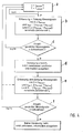
- Fig. 1 shows in the form of a schematic representation of an inventive motor vehicle 1, comprising a driver assistance system 2, for example, a distance holding system, with an associated control unit 3 and a plurality of vehicle front side arranged radar sensors 4, of which Fig. 1 only one is shown.
- the radar sensors 4, which are controlled by the control device 3, send signals and receive reflection signals, the control device 3 determines therefrom the presence of any object in the vehicle apron, and controls the components of the driver assistance system 2 in accordance with the system-inherent function.
- the control device 3 is designed to detect a possible icing of a radar sensor 4, which will be discussed in more detail below.
- the driver assistance system 2 can be deactivated via the control device 3; the driver can be given optical or acoustic information via an optical display device 5, such as a small screen or an acoustic display device 6 such as the integrated loudspeaker system, that the driver assistance system was either automatically disabled, or icing is given and the driver assistance system may not work reliably.
- the control device 3 is also able to detect a change in state, to the effect that the icing is no longer present, and then to reactivate the driver assistance system 2 and to output corresponding information via the display means 5, 6.
- Fig. 2 shows in the form of a schematic representation of a radar image or the course of individual measurement signals, as they result at full functionality of the driver assistance system 2, ie without radar sensor icing. Plotted along the ordinate is the distance of a detected object from the own motor vehicle, along the abscissa the time. As described, each object reflects the emitted radar signal, the radar sensors receive the reflected radar signal, the control device 3 determines the distance of the object from its own vehicle from the measurement signal as the object data. In Fig. 2 the distance is plotted over time, so that the distance of the own vehicle to the preceding object or in this case the preceding objects changing over the time is clearly recognizable.
- the distance values of the individual measurement signals which can be assigned to the respective same objects and are distinguished from one another by corresponding symbols, decrease, that is to say, the own vehicle approaches continuously preceding vehicles.
- An exact resolution is possible, the individual measurement signals can be tracked very accurately and assigned to specific objects.
- step a it is first checked whether the basic prerequisites for a meaningfulness of icing recognition are even met. This is on the one hand, whether the vehicle drives a certain minimum speed, here indicated by V Schwell . It is for example 20 km / h. Another criterion to be checked, whether the ambient temperature T a certain threshold T is smaller threshold, which amounts, for example, +7 or + 4 °. Because only when these conditions are met, on the one hand, is it ensured that the driver assistance system 2 is basically in operation, and, on the other hand, that icing can occur at all.
- step b when the driver assistance system is active and measurement signals are recorded, the measurement signals are started, by means of which specific object data can be determined.
- the distance A so that can be covered by such a measurement signal and counted less than a Schwellabstand is A threshold, which amounts, for example, 2 m or 1.8 m.
- the relative velocity v rel of an object derived from the measurement signal is preferably transmitted to the motor vehicle as a further object data and it is checked whether this relative velocity V rel within a predetermined relative velocity interval [-v threshold ; + v swell], said threshold preferably -v -2 m / s and v + threshold, preferably + 2m / s.
- the lateral tray S can also be determined, which has such a "pseudo-object", which is derived from a measurement signal, to an excellent sensor measuring axis, also checked here whether the lateral filing within a certain storage interval [-S Schwell ; + S threshold ], where -S threshold is preferably -1 m + S threshold +1 m.
- Counted in the present example only those measurement signals in which the distance A ⁇ A threshold and the relative velocity v Rel within the Velocity Interval [-v Threshold ; + v threshold ] is. This count takes place within a predetermined time interval t 1 , which is for example 4 s.
- the measurement interval begins at a certain point in time, for example when a pseudo object measurement signal is present for the first time.
- step c it is now checked whether the counted number corresponds to a predetermined threshold value or is greater than this.
- this comparison threshold value can be, for example, 8 such events or measurement signals. If this is the case, then sufficiently many "pseudoobjects", ie objects that are definitely not in front of the vehicle, are detected, then, as indicated in step d, icing of a radar sensor is assumed, ie the icing is detected.
- the driver assistance system in Fig. 4 abbreviated to FAS, is automatically deactivated via the control device 3, furthermore, alternatively or additionally, information about one of the display means 5, 6 can also be output to the driver.
- the process returns to step a again and checks again whether the conditions for an icing test are met, and if necessary, starts counting again.
- step e a new detection and counting of measurement signals that fulfill the conditions described above, in which thus, the derived distance a ⁇ threshold A and the relative velocity v rel lies within the interval [-v + v swell swell], wherein the lateral tray can be taken into account also optionally, but not necessarily.
- This count takes place within a further time interval t 2 , which can be significantly longer than the first time interval t 1 , for example 60-120 s. Because of this time interval and this re-capture is to ensure that a renewed activation of the driver assistance system only then takes place when it can actually be assumed that there is no more freezing and thus a functionality of the driver assistance system.
- step f will now be made after the time interval t 2, t for example, immediately after the end of the time interval 1 can be triggered for the first time, a new comparison of the counted measurement signal number with a second threshold value, as to whether the counted number is ⁇ the threshold value, which threshold value can also be zero. If this is the case, then sufficiently few erroneous measuring signals are detected, it can be assumed that no more icing is given.
- the control device 3 automatically activates the driver assistance system 2 again, furthermore a corresponding information is output to the driver via one of the display means 5, 6 that the driver assistance system is again available. However, if it is found that the number is greater in number than the threshold value, the method returns to step a, the entire procedure begins again. Alternatively, as shown by the dashed arrow, it is conceivable that the process loop only returns to step e and begins again to acquire and count measurement signals for comparison with the second threshold.
Landscapes
- Engineering & Computer Science (AREA)
- Radar, Positioning & Navigation (AREA)
- Remote Sensing (AREA)
- Computer Networks & Wireless Communication (AREA)
- Physics & Mathematics (AREA)
- General Physics & Mathematics (AREA)
- Radar Systems Or Details Thereof (AREA)
Description
Die Erfindung betrifft ein Verfahren zur Erfassung einer Vereisung eines der Erfassung von Objekten dienenden Radarsensors eines in einem Kraftfahrzeug vorgesehenen Fahrerassistenzsystems, wobei eine den Betrieb des Radarsensors steuernde Steuerungseinrichtung die vom Radarsensor gegebenen Messsignale, die das Vorhandensein eines Objekts anzeigen, auswertet und anhand eines Messsignals Objektdaten umfassend einen Abstand des Objekts und/oder die Relativgeschwindigkeit des Objekts zum Radarsensor und/oder die seitliche Ablage des Objekts zu einer im Signalfächer des Radarsensors liegenden ausgezeichneten Achse ermittelt.The invention relates to a method for detecting icing of a radar sensor provided for detecting objects of a driver assistance system provided in a motor vehicle, wherein a control device controlling the operation of the radar sensor evaluates the measurement signals given by the radar sensor indicating the presence of an object and object data using a measurement signal comprising a distance of the object and / or the relative speed of the object to the radar sensor and / or the lateral storage of the object to a lying in the signal fan of the radar sensor excellent axis determined.
Verschiedene fahrzeugseitig integrierte Fahrerassistenzsysteme, beispielsweise ein Abstandshaltesystem (ACC-System, ACC = adaptiv cruise control) umfassen zumeist fahrzeugfrontseitig vorgesehene Radarsensoren, über die der Abstand des eigenen Fahrzeugs zu einem vorausfahrenden Fahrzeug erfasst werden kann, was durch Analyse der von den Radarsensoren gegebenen Messsignale durch eine zugeordnete Steuerungseinrichtung erfolgt. Aus den Messsignalen kann weiterhin auch die Relativgeschwindigkeit des eigenen Fahrzeugs zum vorausfahrenden Fahrzeug oder die seitliche Ablage des vorausfahrenden Fahrzeugs zum eigenen Fahrzeug ermittelt werden. Die "freie Sicht" der Radarsensoren ist für eine ordnungsgemäße Funktion des Fahrerassistenzsystems entscheidend. Schwierigkeiten können insbesondere im Winter auftreten, wenn sich Schnee oder Schneematsch oder Eis auf dem Radarsensor bzw. der zugeordneten Abdeckung oder Optik ablagern. Um dem zu begegnen, ist es bekannt, Heizeinrichtungen vorzusehen, die ein Ablagern von Schnee oder Schneematsch oder eine Eisbildung verhindern. Jedoch besteht bei ungünstigen Witterungsverhältnissen, z. B. sehr trockener Kälte, und längeren Fahrten die Gefahr, dass der Radarsensor bzw. dessen Optik bzw. die Abdeckung trotz Beheizung vereist. Dabei bildet sich vom Rand her eine Schicht aus blankem Eis, die immer mehr zur Mitte hin zuwächst. Problematisch dabei ist, dass insbesondere Eis in gewissem Maße transparent für Radarstrahlung ist bzw. selbst gesendete Radarstrahlung zurückreflektiert, weshalb herkömmliche Messsignalauswertungen zur Erkennung einer möglichen "Blindheit" eines Radarsensors, also einer Signaldegradation nicht wirksam sind. Derartige Auswertealgorithmen, die einen "Blindheitsindikator" errechnen, berücksichtigen dabei die empfangene Leistung oder die Zahl empfangener Objekte etc. Aufgrund der Reflexionseigenschaften des Eises stellen sich häufig Situationen ein, bei denen diese bekannten Auswertealgorithmen zur Blindheitserfassung einen Blindheitsindikator ermitteln, der deutlich höher als die Abschaltschwelle ist. Denn es wird eine ausreichende rückgestrahlte Energiemenge aufgrund der Eisreflexion ermittelt, wie auch häufig eine Vielzahl von Objekten aufgrund der Eisreflexion erfasst werden können, etc. Eine zuverlässige Objekterkennung ist nicht mehr möglich, da durch die Signalreflexion des Eises fehlerhafte Informationen in die Signalauswertung eingehen bzw Winkelinformationen stark verfälscht werden. Das System müsste eigentlich, da es nicht mehr korrekt arbeitet, abgeschaltet werden, die Abschalterkennung ist jedoch nicht zwingend möglich.Various vehicle-integrated driver assistance systems, such as a ACC system (ACC, adaptive cruise control) include mostly provided on the vehicle front radar sensors over which the distance of the own vehicle can be detected to a vehicle in front, which by analyzing the signals given by the radar sensors by an associated control device takes place. From the measurement signals, the relative speed of the own vehicle to the vehicle in front or the lateral storage of the vehicle ahead to the own vehicle can also be determined. The "free view" of the radar sensors is crucial for the proper functioning of the driver assistance system. Difficulties can occur especially in winter when snow or slush or ice settles on the radar sensor or the associated cover or optics. To counter this, it is known to provide heaters that prevent deposition of snow or slush or ice formation. However, in unfavorable weather conditions, eg. Very much dry cold, and longer trips the risk that the radar sensor or its appearance or the cover iced despite heating. This forms a layer of bare ice from the edge, which grows more and more towards the center. The problem with this is that, in particular, ice is transparent to radar radiation to some extent or reflects radar radiation transmitted back itself, which is why conventional measurement signal evaluations are not effective for detecting a possible "blindness" of a radar sensor, ie signal degradation. Such evaluation algorithms, which calculate a "blindness indicator", take into account the received power or the number of received objects, etc. Due to the reflection properties of the ice, situations often arise in which these known blindness detection algorithms determine a blindness indicator that is significantly higher than the switch-off threshold is. Because it is determined a sufficient amount of re-radiated energy due to the Eisreflexion, as well as a variety of objects can be detected due to the ice reflection, etc. A reliable object detection is no longer possible because the signal reflection of the ice erroneous information received in the signal analysis or angle information be heavily distorted. The system should actually, because it no longer works correctly, be switched off, the disconnect detection is not necessarily possible.
Aus der
Der Erfindung liegt damit das Problem zugrunde, ein demgegenüber verbessertes Verfahren zur Vereisungserfassung anzugeben, das auch in solchen Fällen eine sichere Erkennung einer Fehlfunktion zulässt.The invention is therefore based on the problem of providing a contrast improved icing detection method, which allows reliable detection of a malfunction even in such cases.
Zur Lösung dieses Problems ist bei einem Verfahren der eingangs genannten Art erfindungsgemäß vorgesehen, dass innerhalb eines vorbestimmten Zeitintervalls die Messsignale erfasst werden, zu denen Objektdaten ermittelt werden, deren Abstand ≤ 3m, insbesondere ≤ 2m zum Radarsensor ist, wobei die Anzahl gezählter Messsignale mit einem Schwellwert verglichen wird und ein Erreichen oder Überschreiten des Schwellwerts im Rahmen der Vereisungserfassung berücksichtigt wird.To solve this problem is provided according to the invention in a method of the type mentioned that within a predetermined Time interval, the measurement signals are detected, for which object data are determined whose distance is ≤ 3m, in particular ≤ 2m to the radar sensor, wherein the number of counted measurement signals is compared with a threshold value and reaching or exceeding the threshold is taken into account in the icing detection.
Beim erfindungsgemäßen Verfahren ist der zentrale, im Rahmen der Vereisungserfassung ausgewählte Parameter der Abstand eines Objekts zum eigenen Kraftfahrzeug, der aus den gegebenen Messsignalen eines Radarsensors ermittelt wird. Werden Messsignale aufgrund einer Eisreflexion erzeugt, so zeigen die Messsignale "Pseudoobjekte" an bzw. werden zu den Messsignalen entsprechende Pseudoobjektabstände ermittelt, die extrem nah zum eigenen Kraftfahrzeug sind. Dies resultiert daraus, dass die Eisschicht unmittelbar auf dem Radarsensor aufgewachsen ist. Im erfindungsgemäßen Verfahren werden nun zu allen aufgenommenen Messsignalen die entsprechenden Abstandsobjektdaten ermittelt. Die Messsignale, zu denen sehr geringe Abstände ermittelt werden, also Abstände, die erfindungsgemäß ≤ 3m, vorzugsweise ≤ 2m zu eigenen Fahrzeug sind, werden innerhalb des Zeitintervalls gezählt und kontinuierlich bereits während der Zählung oder nach Ablauf des Zeitintervalls mit einem Vergleichs-Schwellwert verglichen. Ist die gezählte Anzahl größer als der Schwellwert, so wird die Steuerungseinrichtung diese Information oder diesen Umstand im Rahmen der Vereisungserfassung berücksichtigen, wobei eine Vereisung bereits dann erkannt werden kann, wenn ausschließlich der Schwellwert überschritten wird, oder wenn, worauf nachfolgend noch eingegangen wird, zusätzliche weitere Randbedingungen erfüllt sind. Ist der Schwellwert nicht überschritten, ist also eine sehr geringe Anzahl an "Pseudoobjekten" in unmittelbarer, extremer Nähe zum Fahrzeug erfasst worden, ist nicht von einer Vereisung auszugehen.In the method according to the invention, the central parameter selected in the context of the icing detection is the distance of an object to its own motor vehicle, which is determined from the given measuring signals of a radar sensor. If measurement signals are generated as a result of ice reflection, the measurement signals indicate "pseudoobjects" or pseudo-object distances corresponding to the measurement signals which are extremely close to the own motor vehicle are determined. This results from the fact that the ice layer has grown directly on the radar sensor. In the method according to the invention, the corresponding distance object data are now determined for all recorded measurement signals. The measurement signals to which very small distances are determined, ie distances which are according to the invention ≤ 3m, preferably ≤ 2m to own vehicle, are counted within the time interval and compared continuously during the count or after the expiration of the time interval with a comparison threshold. If the counted number is greater than the threshold, the controller will consider this information or circumstance as part of the icing detection, where icing may already be detected when only the threshold is exceeded or, as will be discussed below, additional additional boundary conditions are fulfilled. If the threshold is not exceeded, so that a very small number of "pseudoobjects" has been detected in the immediate, extreme proximity to the vehicle, icing is not to be assumed.
Grundlegender Überwachungsparameter für eine mögliche Vereisung ist also der Abstand etwaiger reflexionsbedingt angenommener "Pseudoobjekte", die sich in einem eigentlich nicht möglichen Abstand vor dem Kraftfahrzeug befinden. Die ermittelte Anzahl dieser Messsignale geht erfindungsgemäß, so sie einen Schwellwert überschreitet, in die Vereisungserfassungsprüfung ein. Es erfolgt hier also quasi eine Plausibilitätsprüfung der Messsignale dahingehend, ob ein ermittelter Zustand, nämlich das Vorhandensein einer Vielzahl von Objekten unmittelbar vor dem eigenen Fahrzeug, überhaupt möglich ist, wobei erfindungsgemäß davon ausgegangen wird, dass ein Fehlerfall vorliegt, wenn eben eine hinreichende Anzahl solcher "Pseudoobjekte" erkannt wird, da dies bei normalen Fahrsituationen eben nicht der Fall ist.The basic monitoring parameter for possible icing is therefore the distance of any reflection-related assumed "pseudoobjects" which are located in an actually not possible distance in front of the motor vehicle. The determined number of these measurement signals is according to the invention, if it exceeds a threshold in the icing detection test. Thus, a plausibility check of the measurement signals takes place, as it were, as to whether a determined condition, namely the presence of a large number of objects directly in front of one's own vehicle, is at all possible, it being assumed according to the invention that there is a fault, if just a sufficient number of such "Pseudoobjekte" is detected, since this is not the case in normal driving situations.
In besonders zweckmäßiger Weiterbildung werden nur Messsignale erfasst und gezählt, zu denen zusätzlich Objektdaten ermittelt werden, deren Relativgeschwindigkeit im Bereich zwischen -3m/s bis +3m/s, insbesondere zwischen -2m/s bis +2m/s liegt, und/oder deren seitliche Ablage zu einer ausgezeichneten Messachse des Radarsensors im Bereich zwischen -1,5m bis +1,5m, insbesondere zwischen -1m bis +1m liegt, wobei eine Vereisung erfasst wird, wenn der Schwellwert erreicht oder überschritten wird. Gemäß dieser Erfindungsausgestaltung wird ein oder werden zwei weitere Parameter im Rahmen einer Vereisungserfassung zusätzlich zu den Abstandsobjektdaten berücksichtigt.In a particularly expedient development, only measurement signals are detected and counted, to which additional object data are determined whose relative speed is in the range between -3m / s to + 3m / s, in particular between -2m / s to + 2m / s, and / or their lateral deposition to an excellent measuring axis of the radar sensor in the range between -1.5m to + 1.5m, in particular between -1m to + 1m, with icing is detected when the threshold is reached or exceeded. According to this embodiment of the invention, one or two further parameters are taken into account in the context of a glaciation detection in addition to the distance object data.
Anhand fehlerhafter Messsignale, also von der Eisschicht reflektierter Messsignale, können ferner extrem niedrige Relativgeschwindigkeiten zwischen dem aus dem Messsignal ermittelten "Pseudoobjekt" und dem eigenen Kraftfahrzeug bestimmt werden. Denn die Eisschicht ist lagefest, ändert also ihre Position nicht. Infolgedessen werden solchen "Pseudoobjekten" häufig Relativgeschwindigkeiten von 0m/s zugeordnet, das heißt, die Signalauswertung ergibt zwangsläufig, dass sich solche "Pseudoobjekte" mit dem Fahrzeug mitbewegen. Erfindungsgemäß können nun nur solche Messsignale erfasst und gezählt werden, bei denen zum einen ein extrem niedriger Abstand im erfindungsgemäßen Intervall ermittelt wird, und bei denen zum anderen eine extrem niedrige Relativgeschwindigkeit ermittelt wird. Alternativ zur Berücksichtigung der Relativgeschwindigkeit besteht auch die Möglichkeit, die seitliche Ablage eines "Pseudoobjekts" zu ermitteln. Auch über die seitliche Ablage kann eine weitere Plausibilisierung fehlerhafter Messsignale erfolgen, die dann tatsächlich zu erfassen und zählen sind. Zweckmäßigerweise können auch beide zusätzlichen Parameter berücksichtigt werden, so dass insgesamt nur Messsignale gezählt werden, bei denen sowohl der Abstand als auch die Relativgeschwindigkeit als auch die seitliche Ablage innerhalb der geforderten Intervalle liegen.On the basis of erroneous measurement signals, that is to say measurement signals reflected by the ice layer, furthermore extremely low relative speeds between the "pseudo object" determined from the measurement signal and the own motor vehicle can be determined. Because the ice layer is stable, so do not change their position. As a result, such "pseudo-objects" are often assigned relative velocities of 0m / s, that is, the signal evaluation inevitably results in such "pseudo-objects" moving with the vehicle. According to the invention, only those measurement signals can now be detected and counted in which, on the one hand, an extremely low distance is determined in the interval according to the invention, and on the other hand, an extremely low relative speed is determined. As an alternative to consideration of the relative velocity, it is also possible to determine the lateral storage of a "pseudo object". Also via the lateral filing, a further plausibility check of erroneous measurement signals can take place, which are then actually to be detected and counted. Appropriately, can Both additional parameters are taken into account, so that in total only measurement signals are counted, in which both the distance and the relative speed and the lateral storage are within the required intervals.
Das Zeitintervall sollte ≤ 20s, insbesondere ≤10s lang sein, vorzugsweise sollte es ca. 4s betragen. Je kürzer das Zeitintervall ist, mithin also die Erfassungs- und Auswertezeit, desto schneller kann auf einen Fehlerzustand geschlossen werden und im Bedarfsfall das Fahrerassistenzsystem abgeschaltet oder als inaktiv gekennzeichnet werden.The time interval should be ≦ 20 s, in particular ≦ 10 s, preferably it should be about 4 s. The shorter the time interval, ie the detection and evaluation time, the faster it can be concluded that an error condition has occurred and, if necessary, the driver assistance system is switched off or marked as inactive.
Der Vergleichs-Schwellwert, mit dem die gezählte Signalanzahl verglichen wird, kann zwischen 2 und 100 betragen. Bei einem kurzen Zeitintervall von beispielsweise 4s ist ein Schwellwert von beispielsweise 8 zweckmäßig, das heißt, es müssen mindestens acht "Pseudoobjekte" erfasst werden, um den Schwellwert zu erreichen, bzw. mindestens 9 "Pseudoobjekte" für ein Überschreiten und zu einer Vereisungserkennung zu führen.The comparison threshold at which the counted number of signals is compared may be between 2 and 100. For a short time interval of, for example, 4 s, a threshold value of, for example, 8 is expedient, that is, at least eight "pseudoobjects" must be detected in order to reach the threshold value, or at least 9 "pseudoobjects" for exceeding and leading to icing detection ,
Zweckmäßigerweise wird die Vereisungserkennung nur dann durchgeführt, wenn die Ist-Geschwindigkeit des Fahrzeugs größer einer Schwellgeschwindigkeit ist. Ist der Radarsensor beispielsweise Teil eines Abstandhaltesystems (ACC-Systems), so macht eine Vereisungsüberprüfung nur dann Sinn, wenn das ACC-System grundsätzlich aktiv ist, was nur dann der Fall ist, wenn das Fahrzeug eine bestimmte Mindestgeschwindigkeit fährt. Diese Schwellgeschwindigkeit kann beispielsweise 10 km/h, vorzugsweise wenigstens 20 km/h betragen. Ist das Fahrzeug langsamer, ist die Vereisungserkennung nicht aktiv, zumal insbesondere bei Geschwindigkeiten ≤ 10 km/h durchaus auch reale Objekte in einem Abstand von weniger als 3m zum eigenen Fahrzeug sein können.Conveniently, the icing detection is performed only when the actual speed of the vehicle is greater than a threshold speed. If, for example, the radar sensor is part of a distance-keeping system (ACC system), an icing check only makes sense if the ACC system is basically active, which is the case only if the vehicle is driving at a certain minimum speed. This threshold speed may be, for example, 10 km / h, preferably at least 20 km / h. If the vehicle is slower, the icing detection is not active, especially as at speeds ≤ 10 km / h can be quite real objects at a distance of less than 3m to your own vehicle.
In vorteilhafter Weiterbildung der Erfindung kann ferner die Vereisungserkennung auch nur dann durchgeführt werden, wenn die Umgebungstemperatur kleiner als eine Schwelltemperatur ist. Eine Vereisung kann zwangsläufig nur bei relativ niedrigen Temperaturen gegeben sein, so dass eine Vereisungserfassung auch nur dann Sinn macht, wenn es hinreichend kalt ist. Eine Schwelltemperatur kann beispielsweise +7 °C oder weniger betragen. Bereits bei Temperaturen im Plus-Gradbereich kann es insbesondere durch den Fahrtwind zu leichten Vereisungen kommen, weshalb eine Vereisungserfassung dann bereits grundsätzlich sinnvoll sein kann.In an advantageous embodiment of the invention, the icing detection can also be carried out only if the ambient temperature is less than a threshold temperature. An icing can be inevitably only given at relatively low temperatures, so that icing detection only makes sense if it is sufficiently cold. For example, a threshold temperature may be +7 ° C or less. Already at temperatures in the plus-degree range, slight icing may occur, in particular due to the airstream, which is why icing detection can already make sense in principle.
Weiterhin kann die Vereisungserfassung auch nur dann durchgeführt werden, wenn eine Scheibenwischeinrichtung inaktiv ist. Wird der Scheibenwischer betätigt, so liegt in der Regel Feuchtigkeit auf der Scheibe, sei es Regen oder Nebelniederschlag. In der Regel kann es dann ebenfalls nicht zu einem Vereisen kommen, da sich ansonsten auf der Windschutzscheibe eine Eisschicht bilden würde und die Betätigung des Scheibenwischers sinnvoll ist. Gegebenenfalls kann zur Entscheidung, ob die Vereisungserkennung aktiviert wird oder nicht, auch berücksichtigt werden, wie lange die Scheibenwischeinrichtung aktiviert wird.Furthermore, the icing detection can also be performed only when a windshield wiper device is inactive. If the windshield wiper is actuated, there is usually moisture on the windshield, be it rain or mist precipitation. In general, it can then also do not come to icing, otherwise an ice sheet would form on the windshield and the operation of the windshield wiper is useful. Optionally, to decide whether the icing detection is activated or not, also be taken into account how long the windshield wiper device is activated.
Wird eine Vereisung erkannt, kann entweder das Fahrerassistenzsystem automatisch über die Steuerungseinrichtung deaktiviert werden, und/oder dem Fahrer eine Warninformation gegeben werden, dass das Fahrerassistenzsystem möglicherweise nicht mehr richtig arbeitet, da eine Vereisung gegeben ist. Die Warninformation kann auch angeben, dass das Fahrerassistenzsystem automatisch deaktiviert wurde.If icing is detected, either the driver assistance system can be automatically deactivated via the control device, and / or the driver can be given warning information that the driver assistance system may no longer be working properly, since there is icing. The warning information may also indicate that the driver assistance system has been automatically deactivated.
Eine gegebene Vereisung kann nur ein temporärer Zustand sein. Das heißt, dass das Eis nach kurzer Zeit auch wieder abschmelzen kann, mithin also das vormals fehlerhaft arbeitende Fahrerassistenzsystem wieder fehlerfrei funktionieren kann. Gleichwohl wurde es aber zuvor deaktiviert. Um es nun im Bedarfsfall wieder aktivieren zu können, werden erfindungsgemäß nach einer Vereisungserkennung kontinuierlich weiterhin Messsignale erfasst, wobei, wenn innerhalb eines zweiten Zeitintervalls eine Anzahl an Messsignalen ermittelt wird, zu denen entsprechende Objektdaten ermittelt werden, die gleich oder kleiner als ein zweiter Schwellwert ist, die Deaktivierung des Fahrerassistenzsystem aufgehoben und/oder eine neue Information an den Fahrer ausgegeben wird. Es erfolgt also kontinuierlich eine weitere Messsignalauswertung hinsichtlich der Parameter "Abstand" und gegebenenfalls "Relativgeschwindigkeit" und/oder "seitliche Ablage", wie auch entsprechende Messsignale, die die eingangs genannten Grenzwerte unterschreiten, gezählt werden. Die Anzahl wird wiederum mit einem zweiten Schwellwert verglichen, wobei in Abhängigkeit des Vergleichsergebnisses es entweder bei der gegebenen Deaktivierung des Fahrerassistenzsystems oder dergleichen bleibt, das heißt, der Vereisungszustand ist nach wie vor gegeben. Entspricht oder unterschreitet die gezählte Signalanzahl jedoch den zweiten Schwellwert, so ist von einer Enteisung auszugehen, da eben innerhalb des Überwachungszeitintervalls keine hinreichende Anzahl an "Pseudoobjekten" detektiert wurde, so dass das Fahrerassistenzsystem wieder aktiviert werden kann. Dieses zweite Zeitintervall sollte wenigstens 60s, beispielsweise 120s betragen, so dass ein hinreichend langer Überwachungszeitraum zur Verfügung steht, um Sicherheit dahingehend zu haben, dass eine erkannte Enteisung auch tatsächlich eingetreten sein kann. Der Schwellwert kann auch hier beliebig gewählt werden, er sollte jedoch möglichst niedrig sein, beispielsweise 5 oder 10 Ereignisse, um ausreichend Sicherheit zu haben.A given icing can only be a temporary condition. This means that the ice can melt again after a short time, so therefore the previously erroneous working driver assistance system can work properly again. Nevertheless, it was deactivated before. In order to be able to reactivate it if necessary, measurement signals are continuously detected according to the invention after an icing detection, wherein, if within a second time interval, a number of measurement signals is determined, to which corresponding object data are determined which is equal to or smaller than a second threshold , the deactivation of the driver assistance system is canceled and / or a new information is output to the driver. Thus, there is a continuous measurement signal evaluation with regard to the parameters "distance" and optionally "relative speed" and / or "lateral storage", as well as corresponding measurement signals which fall below the limits mentioned above, are counted. The number is in turn compared with a second threshold, depending on the comparison result, it either remains at the given deactivation of the driver assistance system or the like, that is, the icing condition is still present. However, if the counted number of signals corresponds to or falls below the second threshold value, defrosting is to be assumed, since just within the monitoring time interval no sufficient number of "pseudoobjects" has been detected so that the driver assistance system can be reactivated. This second time interval should be at least 60 s, for example 120 s, so that a sufficiently long monitoring period is available in order to be certain that a detected defrosting may actually have occurred. The threshold can also be chosen arbitrarily here, but it should be as low as possible, for example 5 or 10 events, in order to have sufficient security.
Weitere Vorteile, Merkmale und Einzelheiten der Erfindung ergeben sich aus dem im folgenden beschriebenen Ausführungsbeispiel sowie anhand der Zeichnungen. Dabei zeigen:
- Fig. 1
- eine Prinzipdarstellung eines erfindungsgemäßen Kraftfahr- zeugs, geeignet zur Durchführung des erfindungsgemäßen Ver- fahrens,
- Fig. 2
- eine Darstellung eines Radarbilds bzw. des Verlaufs einzelner Messsignale bzw. darauf abgeleiteter Objekte über die Zeit oh- ne Sensorvereisung,
- Fig. 3
- eine Darstellung entsprechend
Fig. 2 mit Sensorvereisung, und - Fig. 4
- ein Ablaufdiagramm zur Darstellung des erfindungsgemäßen Verfahrens.
- Fig. 1
- 3 is a schematic representation of a motor vehicle according to the invention, suitable for carrying out the method according to the invention,
- Fig. 2
- a representation of a radar image or the course of individual measurement signals or objects derived thereon over time without sensor icing,
- Fig. 3
- a representation accordingly
Fig. 2 with sensor icing, and - Fig. 4
- a flow diagram for illustrating the method according to the invention.
Anders im Falle einer Vereisung des Radarsensors, wie in
Hier setzt nun das erfindungsgemäße Verfahren an, indem zur Erkennung einer möglichen Vereisung genau solche fehlerhaften Messsignale berücksichtigt werden. Ein Ablaufdiagramm ist in
Im Schritt a wird zunächst überprüft, ob die grundlegenden Voraussetzungen für eine Sinnhaftigkeit einer Vereisungserkennung überhaupt gegeben sind. Dies ist zum einen, ob das Fahrzeug eine gewisse Mindestgeschwindigkeit fährt, hier durch VSchwell angegeben. Sie beträgt beispielsweise 20 km/h. Ein weiteres zu prüfendes Kriterium ist, ob die Umgebungstemperatur T kleiner einer bestimmten Schwelltemperatur TSchwell ist, die beispielsweise +7 oder +4° beträgt. Denn erst wenn diese Voraussetzungen gegeben sind, ist zum einen sichergestellt, dass das Fahrerassistenzsystem 2 grundsätzlich im Betrieb ist, zum anderen, dass es überhaupt zu einer Vereisung kommen kann.In step a, it is first checked whether the basic prerequisites for a meaningfulness of icing recognition are even met. This is on the one hand, whether the vehicle drives a certain minimum speed, here indicated by V Schwell . It is for example 20 km / h. Another criterion to be checked, whether the ambient temperature T a certain threshold T is smaller threshold, which amounts, for example, +7 or + 4 °. Because only when these conditions are met, on the one hand, is it ensured that the
Sind beide Voraussetzungen erfüllt, so wird im Schritt b, wenn das Fahrerassistenzsystem aktiv ist und Messsignale aufgenommen werden, damit begonnen, die Messsignale zu erfassen, anhand denen spezifische Objektdaten ermittelt werden können. Dies ist zum einen der Abstand A, der, damit ein solches Messsignal erfasst und gezählt werden kann, kleiner als ein Schwellabstand ASchwell ist, der beispielsweise 2m oder 1,8m beträgt. Zusätzlich wird bevorzugt als weiteres Objektdatum die Relativgeschwindigkeit vRel eines aus dem Messsignal abgeleiteten Objekts zum eigenen Kraftfahrzeug übermittelt und überprüft, ob diese Relativgeschwindigkeit VRel innerhalb eines vorgegebenen Relativgeschwindigkeitsintervalls [-vSchwell; +vSchwell] liegt, wobei -vSchwell bevorzugt -2m/s und +vSchwell vorzugsweise +2m/s beträgt. Denn die zu erfassenden "Pseudoobjekte", die aus vereisungsbedingt reflektierten Messsignalen resultieren, bewegen sich letztlich üblicherweise mit dem Fahrzeug mit, da die Eisschicht sich ja selbst mit dem Fahrzeug mitbewegt. Gegebenenfalls kann auch zusätzlich die seitliche Ablage S ermittelt werden, die ein solches "Pseudoobjekt", das aus einem Messsignal abgeleitet wird, zu einer ausgezeichneten Sensormessachse aufweist, wobei auch hier überprüft, ob die seitliche Ablage innerhalb eines bestimmten Ablageintervalls [-SSchwell; +SSchwell] liegt, wobei -SSchwell bevorzugt -1 mund +SSchwell +1 m ist.If both prerequisites are fulfilled, then in step b, when the driver assistance system is active and measurement signals are recorded, the measurement signals are started, by means of which specific object data can be determined. This is on the one hand the distance A, so that can be covered by such a measurement signal and counted less than a Schwellabstand is A threshold, which amounts, for example, 2 m or 1.8 m. In addition, the relative velocity v rel of an object derived from the measurement signal is preferably transmitted to the motor vehicle as a further object data and it is checked whether this relative velocity V rel within a predetermined relative velocity interval [-v threshold ; + v swell], said threshold preferably -v -2 m / s and v + threshold, preferably + 2m / s. After all, the "pseudoobjects" to be detected, which result from measurement signals reflected by icing, usually move along with the vehicle, since the ice layer itself moves with the vehicle. Optionally, the lateral tray S can also be determined, which has such a "pseudo-object", which is derived from a measurement signal, to an excellent sensor measuring axis, also checked here whether the lateral filing within a certain storage interval [-S Schwell ; + S threshold ], where -S threshold is preferably -1 m + S threshold +1 m.
Gezählt werden im vorliegenden Beispiel nur solche Messsignale, bei denen der Abstand A ≤ ASchwell und die Relativgeschwindigkeit vRel innerhalb des Geschwindigkeitsintervalls [-vSchwell; +vSchwell] ist. Diese Zählung erfolgt innerhalb eines vorbestimmten Zeitintervalls t1, das beispielsweise 4s beträgt. Das Messintervall beginnt zu einem bestimmten Zeitpunkt, beispielsweise dann, wenn erstmals ein Pseudoobjekt-Messsignal vorliegt.Counted in the present example, only those measurement signals in which the distance A ≤ A threshold and the relative velocity v Rel within the Velocity Interval [-v Threshold ; + v threshold ] is. This count takes place within a predetermined time interval t 1 , which is for example 4 s. The measurement interval begins at a certain point in time, for example when a pseudo object measurement signal is present for the first time.
Im Schritt c wird nun überprüft, ob die gezählte Anzahl einem vorgegebenen Schwellwert entspricht oder größer als dieser ist. Bei einem Zeitintervall t1 von beispielsweise 4s kann dieser Vergleichs-Schwellwert beispielsweise 8 solcher Ereignisse bzw. Messsignale betragen. Ist dies der Fall, werden also hinreichend viele "Pseudoobjekte", also Objekte, die definitiv nicht vor dem Fahrzeug sind, erfasst, so ist, wie in Schritt d angegeben, von einer Vereisung eines Radarsensors auszugehen, die Vereisung wird also erkannt. Das Fahrerassistenzsystem, in
Für den Fall, dass die gezählte Anzahl kleiner als der Schwellwert ist, kehrt das Verfahren wieder zum Schritt a zurück und überprüft erneut, ob die Voraussetzungen für eine Vereisungsprüfung gegeben sind, und beginnt gegebenenfalls erneut mit der Zählung.In the event that the counted number is less than the threshold value, the process returns to step a again and checks again whether the conditions for an icing test are met, and if necessary, starts counting again.
Wird eine Vereisung erkannt, so erfolgt zur kontinuierlichen Überwachung einer möglichen Zustandsänderung dahingehend, dass das Fahrerassistenzsystem erneut zugeschaltet werden kann und die Vereisung nicht mehr gegeben ist, gemäß Schritt e eine erneute Erfassung und Zählung von Messsignalen, die die eingangs beschriebenen Voraussetzungen erfüllen, bei denen also der abgeleitete Abstand A≤ ASchwell ist und die Relativgeschwindigkeit vRel innerhalb des Intervalls [-vSchwell +vSchwell] liegt, wobei auch hier gegebenenfalls, jedoch nicht zwingend, die seitliche Ablage berücksichtigt werden kann. Diese Zählung erfolgt innerhalb eines weiteren Zeitintervalls t2, das deutlich länger als das erste Zeitintervall t1 sein kann, beispielsweise 60 - 120s. Denn über dieses Zeitintervall und diese erneute Erfassung soll sichergestellt werden, dass eine erneute Aktivierung des Fahrerassistenzsystems nur dann erfolgt, wenn tatsächlich definitiv von einer nicht mehr gegebenen Vereisung und damit einer Funktionsfähigkeit des Fahrerassistenzsystems ausgegangen werden kann.If icing is detected, the continuous monitoring of a possible state change takes place in that the driver assistance system can be switched on again and the icing is no longer present, according to step e, a new detection and counting of measurement signals that fulfill the conditions described above, in which thus, the derived distance a≤ threshold A and the relative velocity v rel lies within the interval [-v + v swell swell], wherein the lateral tray can be taken into account also optionally, but not necessarily. This count takes place within a further time interval t 2 , which can be significantly longer than the first time interval t 1 , for example 60-120 s. Because of this time interval and this re-capture is to ensure that a renewed activation of the driver assistance system only then takes place when it can actually be assumed that there is no more freezing and thus a functionality of the driver assistance system.
Im Schritt f erfolgt nun nach Ablauf des Zeitintervalls t2, das beispielsweise unmittelbar nach Ablauf des Zeitintervalls t1 erstmals angestoßen werden kann, ein erneuter Vergleich der gezählten Messsignalanzahl mit einem zweiten Schwellwert, dahingehend, ob die gezählte Anzahl ≤ dem Schwellwert ist, welcher Schwellwert auch Null sein kann. Ist dies der Fall, werden also hinreichend wenige fehlerhafte Messsignale erfasst, ist davon auszugehen, dass keine Vereisung mehr gegeben ist. Die Steuerungseinrichtung 3 aktiviert selbsttätig das Fahrerassistenzsystem 2 erneut, ferner wird eine entsprechende Information an den Fahrer über eines der Anzeigemittel 5, 6 ausgegeben, dass das Fahrerassistenzsystem wieder zur Verfügung steht. Ergibt sich jedoch, dass die Anzahl zahlenmäßig größer als der Schwellwert ist, so kehrt das Verfahren wieder zum Schritt a zurück, das gesamte Prozedere beginnt von vorne. Alternativ ist es auch, wie durch den gestrichelten Pfeil dargestellt, denkbar, dass die Verfahrensschleife nur zum Schritt e zurückkehrt und erneut mit der Erfassung und Zählung von Messsignalen für einen Vergleich mit dem zweiten Schwellwert beginnt.In step f will now be made after the time interval t 2, t for example, immediately after the end of the time interval 1 can be triggered for the first time, a new comparison of the counted measurement signal number with a second threshold value, as to whether the counted number is ≤ the threshold value, which threshold value can also be zero. If this is the case, then sufficiently few erroneous measuring signals are detected, it can be assumed that no more icing is given. The
Claims (12)
- Method for detecting icing on a radar sensor used for the detection of objects in a driver assistance system (2) provided in a motor vehicle (1) wherein a control device (3) controlling the operation of the radar sensor (4) analyses the measurement signals supplied by the radar sensor (4) which indicate the presence of an object and from a measurement signal determines object data including a distance of the object and/or the velocity of the object relative to the radar sensor and/or the lateral deviation of the object from a singular axis lying within the sweep of the radar sensor (4),
characterized in that
those measurement signals acquired within a predetermined time interval (t1) which yield object data with a distance (A) from the radar sensor (4) of 3 m or less, and in particular 2 m or less, [are counted], the number of such counted measurement signals is compared with a threshold value (S), and the reaching or exceeding of the threshold value is taken into account in the icing analysis. - Method according to Claim 1,
characterized in that
only those measurement signals are acquired and counted which moreover yield object data whose relative velocity lies within the range between -3 m/s and +3 m/s, and in particular between -2 m/s and +2 m/s, and/or whose lateral deviation from a singular measurement axis of the radar sensor (4) lies within the range between -1.5 m and +1.5 m, and in particular between -1 m and +1 m, icing being detected if the threshold value is reached or exceeded. - Method according to Claim 1 or Claim 2,
characterized in that
the time interval is 20 s or less, in particular 10 s or less, and preferably 4 s. - Method according to any one of the preceding claims,
characterized in that
the threshold value for the number of counted measurement signals is between 2 and 100. - Method according to any one of the preceding claims,
characterized in that
the icing detection is performed only if the actual velocity of the vehicle (1) is higher than a threshold velocity. - Method according to Claim 5,
characterized in that
the threshold velocity is at least 10 km/h, preferably 20 km/h. - Method according to any one of the preceding claims,
characterized in that
the icing detection is performed only if the ambient temperature is below a threshold temperature. - Method according to Claim 7,
characterized in that
the threshold temperature is +7°C or lower. - Method according to any one of the preceding claims,
characterized in that
the icing detection is performed [only] if the windscreen wiper is inactive. - Method according to any one of the preceding claims,
characterized in that
upon detection of icing, the driver assistance system is deactivated and/or a warning message is given to the driver. - Method according to Claim 10,
characterized in that
following detection of icing, acquisition of measurement signals continues; if a smaller number of measurement signals yielding corresponding object data are detected within a second time interval than a second threshold value, the deactivation of the driver assistance system (2) is cancelled and/or a new message is output to the driver. - Method according to Claim 11,
characterized in that
the second time interval is at least 60 s, and preferably 120 s.
Applications Claiming Priority (1)
| Application Number | Priority Date | Filing Date | Title |
|---|---|---|---|
| DE102007026033A DE102007026033A1 (en) | 2007-06-04 | 2007-06-04 | Method for detecting icing of a radar sensor serving to detect objects of a driver assistance system provided in a motor vehicle |
Publications (2)
| Publication Number | Publication Date |
|---|---|
| EP2000826A1 EP2000826A1 (en) | 2008-12-10 |
| EP2000826B1 true EP2000826B1 (en) | 2009-10-28 |
Family
ID=39734165
Family Applications (1)
| Application Number | Title | Priority Date | Filing Date |
|---|---|---|---|
| EP08009866A Active EP2000826B1 (en) | 2007-06-04 | 2008-05-30 | Method for recording ice on one of the radar sensors used to record objects in a driver assistance system in a motor vehicle |
Country Status (2)
| Country | Link |
|---|---|
| EP (1) | EP2000826B1 (en) |
| DE (2) | DE102007026033A1 (en) |
Families Citing this family (9)
| Publication number | Priority date | Publication date | Assignee | Title |
|---|---|---|---|---|
| DE102009001243A1 (en) * | 2009-02-27 | 2010-09-09 | Robert Bosch Gmbh | Method for detecting icing in an angle-resolving radar sensor in an angle-resolving radar sensor in a driver assistance system for motor vehicles |
| DE102010064727B3 (en) | 2010-05-28 | 2023-02-09 | Valeo Schalter Und Sensoren Gmbh | Method for detecting a blocked state of an ultrasonic sensor of a motor vehicle, driver assistance device and motor vehicle |
| DE102010021960B4 (en) * | 2010-05-28 | 2021-05-06 | Valeo Schalter Und Sensoren Gmbh | Method for detecting a blocked state of an ultrasonic sensor of a motor vehicle, driver assistance device and motor vehicle |
| DE102013223240B3 (en) * | 2013-11-14 | 2014-10-30 | Volkswagen Aktiengesellschaft | Motor vehicle with occlusion detection for ultrasonic sensors |
| DE102016209318A1 (en) * | 2016-05-30 | 2017-11-30 | Conti Temic Microelectronic Gmbh | Apparatus and method for detecting and filtering radar jammers |
| DE102017106851A1 (en) | 2017-03-30 | 2018-10-04 | Geopraevent Ag | Radar system with clearing device |
| DE102018205656A1 (en) * | 2018-04-13 | 2019-10-17 | Siemens Aktiengesellschaft | Temperature monitoring for the detection of functional impairments of radar sensors of rail vehicles |
| DE102019208217A1 (en) * | 2019-06-05 | 2020-12-10 | Volkswagen Aktiengesellschaft | Method and device for monitoring a sensor for detecting surroundings |
| DE102019209846A1 (en) * | 2019-07-04 | 2021-01-07 | Robert Bosch Gmbh | Method of operating a 3D distance sensor device |
Family Cites Families (6)
| Publication number | Priority date | Publication date | Assignee | Title |
|---|---|---|---|---|
| JP3564800B2 (en) * | 1994-08-30 | 2004-09-15 | 株式会社デンソー | Distance measuring device |
| JP2002131428A (en) * | 2000-10-25 | 2002-05-09 | Mitsubishi Electric Corp | Ultrasonic obstacle detecting device |
| DE10211475A1 (en) * | 2002-03-15 | 2003-09-25 | Bosch Gmbh Robert | Operating state control method for automobile speed control system providing automatic disconnection upon blindness of distance sensors |
| JP3915742B2 (en) * | 2003-06-20 | 2007-05-16 | 株式会社デンソー | Vehicle object recognition device |
| DE102005003970A1 (en) * | 2005-01-27 | 2006-08-03 | Daimlerchrysler Ag | Sensor arrangement`s operability determining method for motor vehicle, involves detecting sensor signals successively for different sub-regions while passing at surrounding region, and determining number of measuring events in latter region |
| JP4188336B2 (en) * | 2005-04-12 | 2008-11-26 | 本田技研工業株式会社 | Object detection device |
-
2007
- 2007-06-04 DE DE102007026033A patent/DE102007026033A1/en not_active Withdrawn
-
2008
- 2008-05-30 EP EP08009866A patent/EP2000826B1/en active Active
- 2008-05-30 DE DE502008000164T patent/DE502008000164D1/en active Active
Also Published As
| Publication number | Publication date |
|---|---|
| DE502008000164D1 (en) | 2009-12-10 |
| EP2000826A1 (en) | 2008-12-10 |
| DE102007026033A1 (en) | 2008-12-11 |
Similar Documents
| Publication | Publication Date | Title |
|---|---|---|
| EP2000826B1 (en) | Method for recording ice on one of the radar sensors used to record objects in a driver assistance system in a motor vehicle | |
| EP2051875B1 (en) | Device for detecting a moving object | |
| DE102006002232B4 (en) | Approach warning with collision detector on commercial vehicle | |
| EP1226453B1 (en) | Method and device for identifying the state of a system for effecting the automatic longitudinal and/or lateral control of a motor vehicle | |
| EP1674356B1 (en) | Method and device for a combined signal evaluation of a rain sensor and a camera | |
| DE69922704T2 (en) | LIGHT INDICATOR AND DATA RECORDER FOR MONITORING THE POSITION OF A VEHICLE IN RELATION TO A PREVIOUS VEHICLE | |
| DE102017112300A1 (en) | ADAPTIVE SPEED CONTROL SYSTEM AND METHOD OF OPERATING THE SAME | |
| WO2009135538A1 (en) | Driver assistance method for moving a motor vehicle and driver assistance device | |
| WO2008083731A1 (en) | Method for determining a driver state using a markov model | |
| DE19945250A1 (en) | Method and device for status detection in a system for automatic longitudinal and / or transverse control in a motor vehicle | |
| EP1861722A1 (en) | Lane detection system and method | |
| DE102018201849A1 (en) | Method for reducing the error rate in an object recognition system | |
| DE102011105074A1 (en) | Method for determining visual range for vehicle, involves determining surrounding of vehicle by camera, where contrast dimensions are determined for object depicted in images, where visual range is determined from contrast dimensions | |
| DE102015003964A1 (en) | Method for the autonomous driving of a trajectory by a motor vehicle | |
| DE102005003970A1 (en) | Sensor arrangement`s operability determining method for motor vehicle, involves detecting sensor signals successively for different sub-regions while passing at surrounding region, and determining number of measuring events in latter region | |
| DE102011109711A1 (en) | Method for detecting hands-on or hands-off situation of driver of motor vehicle, involves determining measurement signal which serves for determining safe hands-on situations | |
| EP2342705B1 (en) | Collision recording system | |
| DE10153000C1 (en) | Process for avoiding fogging on windows of a motor vehicle | |
| DE10224971A1 (en) | Method for cleaning a vehicle service brake comprising a brake disc and brake linings | |
| EP1736384B1 (en) | Device and method to control a sensor arrangement in a vehicle | |
| DE102017122578A1 (en) | Method for suppression of false detections, radar system and driver assistance system | |
| EP3788398A1 (en) | Ultrasonic system of a vehicle for determining the condition of the roadway | |
| DE102009036653A1 (en) | Method for controlling heating device in region of optical sensor system in vehicle, involves providing signals based on evaluated state and measuring variables, so that heating elements of pane surface are controlled | |
| DE19948254C2 (en) | Method for detecting contamination and / or blindness in a sensor operating according to the radar or lidar principle | |
| EP3980803A1 (en) | Method and device for monitoring a sensor used for detecting surroundings |
Legal Events
| Date | Code | Title | Description |
|---|---|---|---|
| PUAI | Public reference made under article 153(3) epc to a published international application that has entered the european phase |
Free format text: ORIGINAL CODE: 0009012 |
|
| AK | Designated contracting states |
Kind code of ref document: A1 Designated state(s): AT BE BG CH CY CZ DE DK EE ES FI FR GB GR HR HU IE IS IT LI LT LU LV MC MT NL NO PL PT RO SE SI SK TR |
|
| AX | Request for extension of the european patent |
Extension state: AL BA MK RS |
|
| 17P | Request for examination filed |
Effective date: 20090204 |
|
| GRAP | Despatch of communication of intention to grant a patent |
Free format text: ORIGINAL CODE: EPIDOSNIGR1 |
|
| AKX | Designation fees paid |
Designated state(s): DE FR GB IT |
|
| GRAS | Grant fee paid |
Free format text: ORIGINAL CODE: EPIDOSNIGR3 |
|
| GRAA | (expected) grant |
Free format text: ORIGINAL CODE: 0009210 |
|
| AK | Designated contracting states |
Kind code of ref document: B1 Designated state(s): DE FR GB IT |
|
| REG | Reference to a national code |
Ref country code: GB Ref legal event code: FG4D Free format text: NOT ENGLISH |
|
| REF | Corresponds to: |
Ref document number: 502008000164 Country of ref document: DE Date of ref document: 20091210 Kind code of ref document: P |
|
| PLBE | No opposition filed within time limit |
Free format text: ORIGINAL CODE: 0009261 |
|
| STAA | Information on the status of an ep patent application or granted ep patent |
Free format text: STATUS: NO OPPOSITION FILED WITHIN TIME LIMIT |
|
| 26N | No opposition filed |
Effective date: 20100729 |
|
| REG | Reference to a national code |
Ref country code: FR Ref legal event code: PLFP Year of fee payment: 9 |
|
| REG | Reference to a national code |
Ref country code: FR Ref legal event code: PLFP Year of fee payment: 10 |
|
| REG | Reference to a national code |
Ref country code: FR Ref legal event code: PLFP Year of fee payment: 11 |
|
| PGFP | Annual fee paid to national office [announced via postgrant information from national office to epo] |
Ref country code: IT Payment date: 20220531 Year of fee payment: 15 Ref country code: GB Payment date: 20220522 Year of fee payment: 15 Ref country code: FR Payment date: 20220520 Year of fee payment: 15 Ref country code: DE Payment date: 20220531 Year of fee payment: 15 |
|
| P01 | Opt-out of the competence of the unified patent court (upc) registered |
Effective date: 20230529 |
|
| REG | Reference to a national code |
Ref country code: DE Ref legal event code: R119 Ref document number: 502008000164 Country of ref document: DE |
|
| GBPC | Gb: european patent ceased through non-payment of renewal fee |
Effective date: 20230530 |
|
| PG25 | Lapsed in a contracting state [announced via postgrant information from national office to epo] |
Ref country code: IT Free format text: LAPSE BECAUSE OF NON-PAYMENT OF DUE FEES Effective date: 20230530 Ref country code: DE Free format text: LAPSE BECAUSE OF NON-PAYMENT OF DUE FEES Effective date: 20231201 Ref country code: GB Free format text: LAPSE BECAUSE OF NON-PAYMENT OF DUE FEES Effective date: 20230530 |