EP1993183A1 - Power system stabilizing system - Google Patents
Power system stabilizing system Download PDFInfo
- Publication number
- EP1993183A1 EP1993183A1 EP06713752A EP06713752A EP1993183A1 EP 1993183 A1 EP1993183 A1 EP 1993183A1 EP 06713752 A EP06713752 A EP 06713752A EP 06713752 A EP06713752 A EP 06713752A EP 1993183 A1 EP1993183 A1 EP 1993183A1
- Authority
- EP
- European Patent Office
- Prior art keywords
- power
- frequency
- electric
- dead zone
- hot water
- Prior art date
- Legal status (The legal status is an assumption and is not a legal conclusion. Google has not performed a legal analysis and makes no representation as to the accuracy of the status listed.)
- Granted
Links
Images
Classifications
-
- H—ELECTRICITY
- H02—GENERATION; CONVERSION OR DISTRIBUTION OF ELECTRIC POWER
- H02J—CIRCUIT ARRANGEMENTS OR SYSTEMS FOR SUPPLYING OR DISTRIBUTING ELECTRIC POWER; SYSTEMS FOR STORING ELECTRIC ENERGY
- H02J3/00—Circuit arrangements for ac mains or ac distribution networks
- H02J3/28—Arrangements for balancing of the load in a network by storage of energy
-
- G—PHYSICS
- G06—COMPUTING; CALCULATING OR COUNTING
- G06Q—INFORMATION AND COMMUNICATION TECHNOLOGY [ICT] SPECIALLY ADAPTED FOR ADMINISTRATIVE, COMMERCIAL, FINANCIAL, MANAGERIAL OR SUPERVISORY PURPOSES; SYSTEMS OR METHODS SPECIALLY ADAPTED FOR ADMINISTRATIVE, COMMERCIAL, FINANCIAL, MANAGERIAL OR SUPERVISORY PURPOSES, NOT OTHERWISE PROVIDED FOR
- G06Q50/00—Systems or methods specially adapted for specific business sectors, e.g. utilities or tourism
- G06Q50/06—Electricity, gas or water supply
-
- H—ELECTRICITY
- H02—GENERATION; CONVERSION OR DISTRIBUTION OF ELECTRIC POWER
- H02J—CIRCUIT ARRANGEMENTS OR SYSTEMS FOR SUPPLYING OR DISTRIBUTING ELECTRIC POWER; SYSTEMS FOR STORING ELECTRIC ENERGY
- H02J3/00—Circuit arrangements for ac mains or ac distribution networks
- H02J3/12—Circuit arrangements for ac mains or ac distribution networks for adjusting voltage in ac networks by changing a characteristic of the network load
- H02J3/14—Circuit arrangements for ac mains or ac distribution networks for adjusting voltage in ac networks by changing a characteristic of the network load by switching loads on to, or off from, network, e.g. progressively balanced loading
-
- H—ELECTRICITY
- H02—GENERATION; CONVERSION OR DISTRIBUTION OF ELECTRIC POWER
- H02J—CIRCUIT ARRANGEMENTS OR SYSTEMS FOR SUPPLYING OR DISTRIBUTING ELECTRIC POWER; SYSTEMS FOR STORING ELECTRIC ENERGY
- H02J2310/00—The network for supplying or distributing electric power characterised by its spatial reach or by the load
- H02J2310/10—The network having a local or delimited stationary reach
- H02J2310/12—The local stationary network supplying a household or a building
- H02J2310/14—The load or loads being home appliances
-
- H—ELECTRICITY
- H02—GENERATION; CONVERSION OR DISTRIBUTION OF ELECTRIC POWER
- H02J—CIRCUIT ARRANGEMENTS OR SYSTEMS FOR SUPPLYING OR DISTRIBUTING ELECTRIC POWER; SYSTEMS FOR STORING ELECTRIC ENERGY
- H02J2310/00—The network for supplying or distributing electric power characterised by its spatial reach or by the load
- H02J2310/50—The network for supplying or distributing electric power characterised by its spatial reach or by the load for selectively controlling the operation of the loads
- H02J2310/56—The network for supplying or distributing electric power characterised by its spatial reach or by the load for selectively controlling the operation of the loads characterised by the condition upon which the selective controlling is based
- H02J2310/62—The condition being non-electrical, e.g. temperature
- H02J2310/64—The condition being economic, e.g. tariff based load management
-
- Y—GENERAL TAGGING OF NEW TECHNOLOGICAL DEVELOPMENTS; GENERAL TAGGING OF CROSS-SECTIONAL TECHNOLOGIES SPANNING OVER SEVERAL SECTIONS OF THE IPC; TECHNICAL SUBJECTS COVERED BY FORMER USPC CROSS-REFERENCE ART COLLECTIONS [XRACs] AND DIGESTS
- Y02—TECHNOLOGIES OR APPLICATIONS FOR MITIGATION OR ADAPTATION AGAINST CLIMATE CHANGE
- Y02B—CLIMATE CHANGE MITIGATION TECHNOLOGIES RELATED TO BUILDINGS, e.g. HOUSING, HOUSE APPLIANCES OR RELATED END-USER APPLICATIONS
- Y02B70/00—Technologies for an efficient end-user side electric power management and consumption
- Y02B70/30—Systems integrating technologies related to power network operation and communication or information technologies for improving the carbon footprint of the management of residential or tertiary loads, i.e. smart grids as climate change mitigation technology in the buildings sector, including also the last stages of power distribution and the control, monitoring or operating management systems at local level
- Y02B70/3225—Demand response systems, e.g. load shedding, peak shaving
-
- Y—GENERAL TAGGING OF NEW TECHNOLOGICAL DEVELOPMENTS; GENERAL TAGGING OF CROSS-SECTIONAL TECHNOLOGIES SPANNING OVER SEVERAL SECTIONS OF THE IPC; TECHNICAL SUBJECTS COVERED BY FORMER USPC CROSS-REFERENCE ART COLLECTIONS [XRACs] AND DIGESTS
- Y04—INFORMATION OR COMMUNICATION TECHNOLOGIES HAVING AN IMPACT ON OTHER TECHNOLOGY AREAS
- Y04S—SYSTEMS INTEGRATING TECHNOLOGIES RELATED TO POWER NETWORK OPERATION, COMMUNICATION OR INFORMATION TECHNOLOGIES FOR IMPROVING THE ELECTRICAL POWER GENERATION, TRANSMISSION, DISTRIBUTION, MANAGEMENT OR USAGE, i.e. SMART GRIDS
- Y04S20/00—Management or operation of end-user stationary applications or the last stages of power distribution; Controlling, monitoring or operating thereof
- Y04S20/20—End-user application control systems
- Y04S20/222—Demand response systems, e.g. load shedding, peak shaving
-
- Y—GENERAL TAGGING OF NEW TECHNOLOGICAL DEVELOPMENTS; GENERAL TAGGING OF CROSS-SECTIONAL TECHNOLOGIES SPANNING OVER SEVERAL SECTIONS OF THE IPC; TECHNICAL SUBJECTS COVERED BY FORMER USPC CROSS-REFERENCE ART COLLECTIONS [XRACs] AND DIGESTS
- Y04—INFORMATION OR COMMUNICATION TECHNOLOGIES HAVING AN IMPACT ON OTHER TECHNOLOGY AREAS
- Y04S—SYSTEMS INTEGRATING TECHNOLOGIES RELATED TO POWER NETWORK OPERATION, COMMUNICATION OR INFORMATION TECHNOLOGIES FOR IMPROVING THE ELECTRICAL POWER GENERATION, TRANSMISSION, DISTRIBUTION, MANAGEMENT OR USAGE, i.e. SMART GRIDS
- Y04S20/00—Management or operation of end-user stationary applications or the last stages of power distribution; Controlling, monitoring or operating thereof
- Y04S20/20—End-user application control systems
- Y04S20/242—Home appliances
-
- Y—GENERAL TAGGING OF NEW TECHNOLOGICAL DEVELOPMENTS; GENERAL TAGGING OF CROSS-SECTIONAL TECHNOLOGIES SPANNING OVER SEVERAL SECTIONS OF THE IPC; TECHNICAL SUBJECTS COVERED BY FORMER USPC CROSS-REFERENCE ART COLLECTIONS [XRACs] AND DIGESTS
- Y04—INFORMATION OR COMMUNICATION TECHNOLOGIES HAVING AN IMPACT ON OTHER TECHNOLOGY AREAS
- Y04S—SYSTEMS INTEGRATING TECHNOLOGIES RELATED TO POWER NETWORK OPERATION, COMMUNICATION OR INFORMATION TECHNOLOGIES FOR IMPROVING THE ELECTRICAL POWER GENERATION, TRANSMISSION, DISTRIBUTION, MANAGEMENT OR USAGE, i.e. SMART GRIDS
- Y04S50/00—Market activities related to the operation of systems integrating technologies related to power network operation or related to communication or information technologies
- Y04S50/10—Energy trading, including energy flowing from end-user application to grid
Definitions
- the present invention relates to a power system stabilization system that serves to stabilize the quality of power in a regional energy supply system having natural energy power generation.
- a conventional regional energy supply system provided with natural energy electric power generation equipment using natural energy such as wind power, solar power, etc., has a distributed power supply device with a storage battery for eliminating the instability of power supply due to frequent output fluctuations thereof, and includes an optimum system operation planning section that creates an optimum operation plan of the distributed power supply device, and a control command value decision section that stores an amount of accumulated or stored electricity (electric power) and the cost for accumulating or storing electricity (electric power) by measuring and summing the amount of charge and discharge and the charging cost of the storage battery, wherein when it is determined, by the calculation of simulating the cases when the amount of charge and discharge of the storage battery is increased or decreased, that the sum of an amount of variation of the cost of buying and selling electric power due to the transmission (receiving and sending) thereof with an electric power system and an amount of variation of the charging cost due to the amount of charge and discharge of the storage battery becomes negative, the control command value decision section changes a control command value for the amount of charge and discharge of the storage battery in the process of
- the electricity accumulation or storage equipment has the problem that it is high in cost and the service life thereof is short in comparison with other equipment.
- the object of the present invention is to provide a power system stabilization system which serves to make it stable at a low cost to maintain the demand and supply of electric power within a regional energy supply system or the quality of electric power of a commercial power system in which an amount of natural energy power generation introduced has been increased.
- the power system stabilization system includes: an electric water heater that receives electric power from the electric power system and heats water; a system frequency measuring device that measures a system frequency of the electric power system; and a hot water controller that increases the power consumption of the electric water heater when the system frequency exceeds a reference frequency, and on the contrary, decreases the power consumption of the electric water heater when the system frequency is less than the reference frequency, whereby the frequency of the electric power system is maintained within a predetermined range.
- the advantageous effects of the power system stabilization system according to the present invention are as follows. That is, the balance of the power demand and supply of the electric power system is recovered by increasing and decreasing the power consumption of an electric water heater based on a system frequency controlled by a rotating power generator in accordance with the demand and supply balance of the electric power system, and the system stabilization system can be achieved at a low cost because the electric water heater is in general existing with customers.
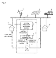
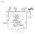
- FIG. 1 is a block diagram of a power system provided with a power system stabilization system according to a first embodiment of the present invention.
- a power system stabilization system 1 according to the first embodiment of the present invention is intended to maintain and stabilize the power quality of an electric power system 5 of a regional energy supply system to which a rotating power generator 2, which generates electric power by combusting fossil fuel, wind power generation equipment 3 and photovoltaic generation equipment 4, which serve to perform natural energy power generation, are connected.
- a customer 6 is connected to this electric power system 5, wherein electric power is supplied not by an electric power company but by a small-scale system.
- warm water is also supplied to the regional energy supply system.
- the power system stabilization system 1 includes a system frequency measuring device 10 for measuring the system frequency of the electric power system 5, an electric water heater 11 for supplying warm water to the customer 6, and a hot water controller 12 for controlling the operation of the electric water heater 11 based on the system frequency and the amount of hot water in the electric water heater 11.
- This electric water heater 11 is supplied with electric power from the electric power system 5 to heat water.
- This electric water heater 11 is an electric water heater, a heat pump water heater, etc.
- the frequency of the electric power system 5 is decided by the rotating power generator 2, and the wind power generation equipment 3 and the photovoltaic generation equipment 4 are synchronized with the frequency to generate electricity. If the balance of electric power supply and demand in the electric power system 5 can be maintained, the rotating power generator 2 generates electricity at a constant frequency. When the power demand and supply balance is broken to bring about an excess of supply, the frequency of the rotating power generator 2 rises naturally due to the characteristic of the rotating power generator 2, whereas on the contrary, when the power supply becomes short, the frequency comes down naturally. Accordingly, the balance of power supply and demand in the electric power system 5 can generally be determined by taking the system frequency into consideration.
- a reference frequency of the electric power system is set to F0 Hz
- FC Hz when the system frequency FC Hz exceeds the reference frequency F0, it means that the power supply exceeds the power demand
- the system frequency FC when the system frequency FC is lower than the reference frequency F0, it means that the power demand exceeds the power supply.
- the system frequency measuring device 10 serves to measure the system frequency FC that varies naturally in this manner due to the unbalance of supply and demand of electric power, and send it to the hot water controller 12.
- a dead zone which extends above and below the reference frequency F0 so as to be sandwiched between a dead zone upper limit Fd1 Hz and a dead zone lower limit Fd2 Hz.
- an up side control delay time TUP is set at the time when the system frequency FC exceeds the dead zone upper limit Fd1
- a down side control delay time TDN is set at the time when the system frequency FC is less than the dead zone lower limit Fd2.
- a hot water storage rate upper limit and a hot water storage rate lower limit are provided for the amount of hot water stored in the electric water heater 11.
- the dead zone is moved to a high frequency side, and the up side control delay time TUP is made longer and the down side control delay time TDN is made shorter.
- the dead zone is moved to a low frequency side, and the up side control delay time TUP is made shorter and the down side control delay time TDN is made longer.
- the hot water controller 12 changes the dead zone, the up side control delay time TUP and the down side control delay time TDN based on the hot water storage rate by means of the above-mentioned method. Further, the hot water controller 12 determines the demand and supply balance of electric power based on the system frequency according to the above-mentioned method, and if it is in the excess of power supply, the power demand is increased by making the power consumption of the electric water heater 11 larger to store it as thermal energy, whereas if it is short of the power supply, the power demand is decreased by making the power consumption of the electric water heater 11 smaller.
- the power consumption is increased by a change value ⁇ P of the power consumption that is obtained by multiplying a difference between the system frequency FC and the dead zone upper limit Fd1 by a predetermined coefficient k1.
- the power consumption is decreased by a change value ⁇ P of the power consumption that is obtained by multiplying the difference between the system frequency FC and the dead zone lower limit Fd2 by the predetermined coefficient k1.
- the hot water controller 12 is constituted by a computer that has a CPU, a ROM, a RAM and an interface circuit.
- the electric water heater 11 receives an operation command from the hot water controller 12, and changes the operating state thereof so as to increase and decrease the power consumption thereof by changing conditions such as activation, stopping, an operating load factor, etc.
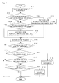
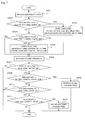
- Fig. 2 is a flow chart of an operation command decision routine that is performed in the hot water supply controller 12.
- this operation command decision routine is activated in a periodic manner.
- step S 101 the hot water storage rate (from 0 when the hot water is empty to 1 when it is full) is calculated from the amount of hot water stored in the electric water heater 11.
- step S102 the hot water storage rate exceeds the hot water storage rate upper limit
- the control process proceeds to step S103, whereas when the hot water storage rate is less than the hot water storage rate upper limit, the control process proceeds to step S104.
- step S103 both the dead zone upper limit and the dead zone lower limit are raised so that water should not be boiled or heated in a preferential manner, and at the same time, the up side delay time until the power consumption is increased is extended, and the down side delay time is shortened, after which the control process proceeds to step S106.
- step S 104 the hot water storage rate is less than the hot water storage rate lower limit
- the control process proceeds to step S105, whereas when the hot water storage rate is equal to or larger than the hot water storage rate lower limit, the control process proceeds to step S106.
- step S15 both the dead zone upper limit and the dead zone lower limit are lowered so that the electric water heater 11 heats or boil the water therein in a preferential manner, and at the same time, the up side delay time until the power consumption is increased is shortened, and the down side delay time is extended, after which the control process proceeds to step S106.
- step S 106 the system frequency is measured and then the control process proceeds to step S107.
- step S 107 it is determined whether the frequency exceeds the dead zone upper limit, and when the frequency exceeds the dead zone upper limit, the control process proceeds to step S108, whereas when the frequency is equal to or less than the dead zone upper limit, the operation command decision routine is terminated.
- step S 108 it is determined whether the period of time in which the frequency exceeds the dead zone upper limit continues for over the up side delay time, and when it continues, the control process proceeds to step S109, whereas when it does not continue, the control process proceeds to step S110.
- step S109 the power consumption of the electric water heater 11 is increased and the operation command decision routine is then terminated.
- step S110 it is determined whether the frequency is less than the dead zone lower limit, and when the frequency is less than the dead zone lower limit, the control process proceeds to step S111, whereas when the frequency is equal to or larger than the dead zone lower limit, the operation command decision routine is terminated.
- step S111 it is determined whether the period of time in which the frequency is less than the dead zone upper limit continues for over the down side delay time, and when it continues, the control process proceeds to step S112, whereas when it does not continue, the operation command decision routine is terminated.
- step S 112 the power consumption of the electric water heater 11 is decreased and the operation command decision routine is then terminated.
- Such a power system stabilization system 1 serves to recover the balance of the power demand and supply of the electric power system 5 by increasing and decreasing the power consumption of the electric water heater 11 based on the system frequency controlled by the rotating power generator 2 in accordance with the demand and supply balance of the electric power system 5, and the electric water heater 11 is generally provided in the customer 6, so it is possible to achieve the power system stabilization system 1 at a low cost.
- the dead zone for the system frequency is determined beforehand, and the power consumption of the electric water heater 11 is increased and decreased only when the system frequency deviates from this dead zone, so it is possible to prevent the power consumption of the electric water heater 11 from changing at all times.
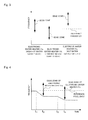
- Fig. 4 shows the operating states of the dead zones of plural power system stabilization systems 1 which are provided in an electric power system 5.
- the hot water storage rate of an electric water heater 11a is high, so the dead zone thereof is located on a high frequency side, and the hot water storage rate of an electric water heater 11b is low, so the dead zone thereof is located on a low frequency side.
- the hot water storage rate of an electric water heater 11c is 1, so the dead zone thereof is located at a high frequency side endpoint.
- the system frequency goes down gradually due to the shortage of the power supply, and at time point t2 at which the system frequency falls below the dead zone lower limit of the electric water heater 11 a, the system frequency is controlled in a direction to decrease the power consumption of the electric water heater 11 a, but at this time point t2, the system frequency remains within the dead zone of the electric water heater 11b, so the power consumption of the electric water heater 11b is not changed.
- the electric water heater 11b is also controlled in a direction to decrease the power consumption thereof.
- the dead zone is located in the high frequency region, so it is possible to prevent a further water boiling or heating operation thereof.
- the rotating power generator 2 generates electricity in accordance with the system frequency of the electric power system, but in case where there is the possibility that power supply shortage will occur in the near future or power generation of a high power generation unit cost will be needed, or the like, as shown in Fig.
- the power generation frequency is intentionally made smaller to lower the system frequency, while on the contrary, in case where there is the possibility that excessive electric power supply will occur or the power generation efficiency will be reduced due to a high electrical load, the power generation frequency is intentionally made larger, thereby increasing the system frequency.
- the rotating power generator 2 predicts the operating condition thereof in the future and changes the system frequency, whereby it is possible to stabilize the electric power system not only at the current point in time but also from after a few minutes.
- Fig. 6 is a block diagram of a power system provided with a power system stabilization system according to a second embodiment of the present invention.
- a power system stabilization system 1B according to the second embodiment of the present invention has a control center 7 added to the power system stabilization system 1 according to the first embodiment, and also has a hot water controller 12B which is different from the one in the first embodiment, but the other construction of this second embodiment is similar to the first embodiment, and hence like components or parts are identified by the same symbols while omitting a detailed explanation thereof.
- the control center 7 acquires data concerning the power generation condition of the rotating power generator 2, the wind power generation equipment 3, and the photovoltaic generation equipment 4, calculates the electricity price of the electric power system 5 at the current point in time in real time, and notifies it the hot water controller 12. In addition, the control center 7 raises the electricity price in case where there is the possibility that power supply shortage will occur in the near future with respect to the electricity price at the current point in time or power generation of a high power generation unit price will be needed, or the like, whereas in the opposite case, it reduces the electricity price, and notifies it to the hot water controller 12B.
- the control center 7, the individual pieces of power generation equipment and the hot water controller 12B are connected with one another by means of a communication line 8.
- an electricity price upper limit and an electricity price lower limit are determined beforehand, and when the electricity price obtained from the control center 7 exceeds the electricity price upper limit, the price of electricity used to supply hot water becomes higher, so heating or boiling water is reduced as much as possible, whereas when, on the contrary, the electricity price obtained from the control center 7 is less than electricity price lower limit, the price of electricity used to supply hot water becomes lower, so heating or boiling hot water is increased as much as possible.
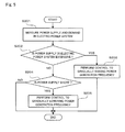
- Fig. 7 is a flow chart of an operation command decision routine that is performed in the hot water supply controller 12B according to the second embodiment.
- the procedure in steps S307 through S311 in Fig. 7 is similar to the procedure in steps S107-S111 in Fig. 2 , so an explanation thereof is omitted, and the procedure in different steps S301 through S305 will be described below.
- this operation command decision routine is activated in a periodic manner.
- an electricity price from the control center 7 is received.
- step S302 the electricity price exceeds the electricity price upper limit
- step S303 both the dead zone upper limit and the dead zone lower limit are raised so that water should not be boiled or heated preferentially, and at the same time, the up side delay time until the power consumption is increased is extended, and the down side delay time is shortened, after which the control process advances to step S306.
- step S304 the electricity price is less than the electricity price lower limit
- step S305 the control process proceeds to step S305, whereas when the hot electricity price is equal to or larger than the electricity price lower limit, the control process proceeds to step S306.
- step S305 both the dead zone upper limit and the dead zone lower limit are lowered so that the electric water heater 11 heats or boil the water therein in a preferential manner, and at the same time, the up side delay time until the power consumption is increased is shortened, and the down side delay time is extended, after which the control process proceeds to step S306.
- Such a power system stabilization system 1B calculates, in the control center 7, the electricity price of the electric power system at the current point in time or in the future, and the amount of water to be boiled or heated is controlled based on the electricity price thus calculated, so it is possible to supply hot water to the customer at a low cost.
- the electricity price is predicted, and the amount of hot water stored in the electric water heater 11 is controlled based the electricity price thus predicted, the power demand and supply balance within the region can be maintained.
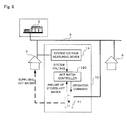
- Fig. 8 is a block diagram of a power distribution system provided with a power system stabilization system according to a third embodiment of the present invention.
- an explanation has been made to the recovery of the unbalance of power supply and demand by increasing and decreasing the power consumption in the electric water heater 11 based on the system frequency that changes depending on the balance of power supply and demand of the electric power system, but in a power system stabilization system 1C according to the third embodiment to be described below, it is a problem to maintain a voltage at a power receiving point of the customer 6.
- the power system stabilization system 1C according to the third embodiment of the present invention has an electric water heater 11 which functions to control power consumption at the power receiving point, as in the power system stabilization system 1 according to the first embodiment.
- the power system stabilization system 1C according to the third embodiment includes, unlike the first embodiment, a system voltage measuring device 14 instead of the system frequency measuring device 10, and a hot water controller C instead of the hot water controller 12.
- the system voltage measuring device 14 according to the third embodiment serves to measure the system voltage at the power receiving point of the customer 6, and to send it to the hot water controller 12C.
- the hot water controller 12C according to the third embodiment serves to control the power consumption of the electric water heater 11 based on the system voltage so that the system voltage is made to coincide with a reference voltage.
- Such a power system stabilization system 1C is able to increase and decrease the power consumption of the electric water heater 11 based on the system voltage at the power receiving point of the customer 6 thereby to keep the voltage at the receiving point constant, and the electric water heater 11 is generally provided in the customer 6, so the voltage at the receiving point can be maintained at the reference voltage at a low cost.
Abstract
Description
- The present invention relates to a power system stabilization system that serves to stabilize the quality of power in a regional energy supply system having natural energy power generation.
- A conventional regional energy supply system provided with natural energy electric power generation equipment using natural energy such as wind power, solar power, etc., has a distributed power supply device with a storage battery for eliminating the instability of power supply due to frequent output fluctuations thereof, and includes an optimum system operation planning section that creates an optimum operation plan of the distributed power supply device, and a control command value decision section that stores an amount of accumulated or stored electricity (electric power) and the cost for accumulating or storing electricity (electric power) by measuring and summing the amount of charge and discharge and the charging cost of the storage battery, wherein when it is determined, by the calculation of simulating the cases when the amount of charge and discharge of the storage battery is increased or decreased, that the sum of an amount of variation of the cost of buying and selling electric power due to the transmission (receiving and sending) thereof with an electric power system and an amount of variation of the charging cost due to the amount of charge and discharge of the storage battery becomes negative, the control command value decision section changes a control command value for the amount of charge and discharge of the storage battery in the process of the optimum operation plan, and sends it to the distributed power supply device (see, for example, a first patent document).
- First Patent Document Japanese patent application laid-open No.
2005-143218 - However, the electricity accumulation or storage equipment has the problem that it is high in cost and the service life thereof is short in comparison with other equipment.
- The object of the present invention is to provide a power system stabilization system which serves to make it stable at a low cost to maintain the demand and supply of electric power within a regional energy supply system or the quality of electric power of a commercial power system in which an amount of natural energy power generation introduced has been increased.
- In a power system stabilization system for stabilizing a small-scale electric power system to which electric power generated by a rotating power generator is supplied, the power system stabilization system according to the present invention includes: an electric water heater that receives electric power from the electric power system and heats water; a system frequency measuring device that measures a system frequency of the electric power system; and a hot water controller that increases the power consumption of the electric water heater when the system frequency exceeds a reference frequency, and on the contrary, decreases the power consumption of the electric water heater when the system frequency is less than the reference frequency, whereby the frequency of the electric power system is maintained within a predetermined range.
- The advantageous effects of the power system stabilization system according to the present invention are as follows. That is, the balance of the power demand and supply of the electric power system is recovered by increasing and decreasing the power consumption of an electric water heater based on a system frequency controlled by a rotating power generator in accordance with the demand and supply balance of the electric power system, and the system stabilization system can be achieved at a low cost because the electric water heater is in general existing with customers.
-
-
Fig. 1 is a block diagram of a power system provided with a power system stabilization system according to a first embodiment of the present invention. -
Fig. 2 is a flow chart of an operation command decision routine that is performed in a hot water supply controller according to the first embodiment. -
Fig. 3 is a graph that shows the magnitude of dead zones in case where there are a plurality of power system stabilization systems. -
Fig. 4 is a graph that shows the change of the power consumption of electric water heaters when a system frequency becomes lower in case where there are a plurality of power system stabilization systems. -
Fig. 5 is a flow chart of a procedure for controlling a power generation frequency by a rotating power generator which predicts the balance between supply and demand of power according to the first embodiment. -
Fig. 6 is a block diagram of a power system provided with a power system stabilization system according to a second embodiment of the present invention. -
Fig. 7 is a flow chart of an operation command decision routine that is performed in a hot water supply controller according to the second embodiment. -
Fig. 8 is a block diagram of a power distribution system provided with a power system stabilization system according to a third embodiment of the present invention. -
Fig. 1 is a block diagram of a power system provided with a power system stabilization system according to a first embodiment of the present invention.
A power system stabilization system 1 according to the first embodiment of the present invention is intended to maintain and stabilize the power quality of anelectric power system 5 of a regional energy supply system to which arotating power generator 2, which generates electric power by combusting fossil fuel, windpower generation equipment 3 andphotovoltaic generation equipment 4, which serve to perform natural energy power generation, are connected. Acustomer 6 is connected to thiselectric power system 5, wherein electric power is supplied not by an electric power company but by a small-scale system. Here, note that warm water is also supplied to the regional energy supply system. - As shown in
Fig. 1 , the power system stabilization system 1 according to the first embodiment includes a systemfrequency measuring device 10 for measuring the system frequency of theelectric power system 5, anelectric water heater 11 for supplying warm water to thecustomer 6, and ahot water controller 12 for controlling the operation of theelectric water heater 11 based on the system frequency and the amount of hot water in theelectric water heater 11. Thiselectric water heater 11 is supplied with electric power from theelectric power system 5 to heat water. Thiselectric water heater 11 is an electric water heater, a heat pump water heater, etc. - The frequency of the
electric power system 5 is decided by the rotatingpower generator 2, and the windpower generation equipment 3 and thephotovoltaic generation equipment 4 are synchronized with the frequency to generate electricity.
If the balance of electric power supply and demand in theelectric power system 5 can be maintained, the rotatingpower generator 2 generates electricity at a constant frequency. When the power demand and supply balance is broken to bring about an excess of supply, the frequency of the rotatingpower generator 2 rises naturally due to the characteristic of therotating power generator 2, whereas on the contrary, when the power supply becomes short, the frequency comes down naturally.
Accordingly, the balance of power supply and demand in theelectric power system 5 can generally be determined by taking the system frequency into consideration. In addition, in case where a reference frequency of the electric power system is set to F0 Hz, when the system frequency FC Hz exceeds the reference frequency F0, it means that the power supply exceeds the power demand, whereas when the system frequency FC is lower than the reference frequency F0, it means that the power demand exceeds the power supply.
The systemfrequency measuring device 10 serves to measure the system frequency FC that varies naturally in this manner due to the unbalance of supply and demand of electric power, and send it to thehot water controller 12. - In a method of recovering the balance between the power supply and demand by increasing and decreasing the power consumption of the
electric water heater 11 according to the present invention, there is provided a dead zone which extends above and below the reference frequency F0 so as to be sandwiched between a dead zone upper limit Fd1 Hz and a dead zone lower limit Fd2 Hz. When the system frequency FC is in the dead zone, the power consumption of theelectric water heater 11 is left as it is, whereas when the system frequency FC deviates from the dead zone, the operating condition of theelectric water heater 11 is changed whereby the power consumption thereof is increased or decreased. Here, it is to be noted that only when the system frequency FC continuously deviates from the dead zone for a predetermined time, it is determined to be actually deviated therefrom, so the operating condition is changed. As such a predetermined time, an up side control delay time TUP is set at the time when the system frequency FC exceeds the dead zone upper limit Fd1, and a down side control delay time TDN is set at the time when the system frequency FC is less than the dead zone lower limit Fd2. - In addition, a hot water storage rate upper limit and a hot water storage rate lower limit are provided for the amount of hot water stored in the
electric water heater 11. When the amount of stored hot water exceeds the hot water storage rate upper limit, the dead zone is moved to a high frequency side, and the up side control delay time TUP is made longer and the down side control delay time TDN is made shorter.
On the contrary, when the amount of stored hot water is less than the hot water storage rate lower limit, the dead zone is moved to a low frequency side, and the up side control delay time TUP is made shorter and the down side control delay time TDN is made longer. - The
hot water controller 12 changes the dead zone, the up side control delay time TUP and the down side control delay time TDN based on the hot water storage rate by means of the above-mentioned method. Further, thehot water controller 12 determines the demand and supply balance of electric power based on the system frequency according to the above-mentioned method, and if it is in the excess of power supply, the power demand is increased by making the power consumption of theelectric water heater 11 larger to store it as thermal energy, whereas if it is short of the power supply, the power demand is decreased by making the power consumption of theelectric water heater 11 smaller.
When it is in the excess of the power supply, the power consumption is increased by a change value ΔP of the power consumption that is obtained by multiplying a difference between the system frequency FC and the dead zone upper limit Fd1 by a predetermined coefficient k1.
On the contrary, when it is short of the power supply, the power consumption is decreased by a change value ΔP of the power consumption that is obtained by multiplying the difference between the system frequency FC and the dead zone lower limit Fd2 by the predetermined coefficient k1.
Here, it is to be noted that when the system frequency FC is within the dead zone or temporarily deviates from the dead zone, the power consumption of theelectric water heater 11 is left just as it is. Thehot water controller 12 is constituted by a computer that has a CPU, a ROM, a RAM and an interface circuit.
Theelectric water heater 11 receives an operation command from thehot water controller 12, and changes the operating state thereof so as to increase and decrease the power consumption thereof by changing conditions such as activation, stopping, an operating load factor, etc. -
Fig. 2 is a flow chart of an operation command decision routine that is performed in the hotwater supply controller 12.
Next, reference will be made to the operation of the power system stabilization system 1 according to this first embodiment while referring toFig. 2 .
When the power system stabilization system 1 is in operation, this operation command decision routine is activated in a periodic manner.
Instep S 101, the hot water storage rate (from 0 when the hot water is empty to 1 when it is full) is calculated from the amount of hot water stored in theelectric water heater 11.
When, in step S102, the hot water storage rate exceeds the hot water storage rate upper limit, the control process proceeds to step S103, whereas when the hot water storage rate is less than the hot water storage rate upper limit, the control process proceeds to step S104.
In step S103, both the dead zone upper limit and the dead zone lower limit are raised so that water should not be boiled or heated in a preferential manner, and at the same time, the up side delay time until the power consumption is increased is extended, and the down side delay time is shortened, after which the control process proceeds to step S106.
When, in step S 104, the hot water storage rate is less than the hot water storage rate lower limit, the control process proceeds to step S105, whereas when the hot water storage rate is equal to or larger than the hot water storage rate lower limit, the control process proceeds to step S106.
In step S15, both the dead zone upper limit and the dead zone lower limit are lowered so that theelectric water heater 11 heats or boil the water therein in a preferential manner, and at the same time, the up side delay time until the power consumption is increased is shortened, and the down side delay time is extended, after which the control process proceeds to step S106.
In step S 106, the system frequency is measured and then the control process proceeds to step S107.
Instep S 107, it is determined whether the frequency exceeds the dead zone upper limit, and when the frequency exceeds the dead zone upper limit, the control process proceeds to step S108, whereas when the frequency is equal to or less than the dead zone upper limit, the operation command decision routine is terminated.
Instep S 108, it is determined whether the period of time in which the frequency exceeds the dead zone upper limit continues for over the up side delay time, and when it continues, the control process proceeds to step S109, whereas when it does not continue, the control process proceeds to step S110.
In step S109, the power consumption of theelectric water heater 11 is increased and the operation command decision routine is then terminated.
In step S110, it is determined whether the frequency is less than the dead zone lower limit, and when the frequency is less than the dead zone lower limit, the control process proceeds to step S111, whereas when the frequency is equal to or larger than the dead zone lower limit, the operation command decision routine is terminated.
In step S111, it is determined whether the period of time in which the frequency is less than the dead zone upper limit continues for over the down side delay time, and when it continues, the control process proceeds to step S112, whereas when it does not continue, the operation command decision routine is terminated.
Instep S 112, the power consumption of theelectric water heater 11 is decreased and the operation command decision routine is then terminated. - Such a power system stabilization system 1 serves to recover the balance of the power demand and supply of the
electric power system 5 by increasing and decreasing the power consumption of theelectric water heater 11 based on the system frequency controlled by therotating power generator 2 in accordance with the demand and supply balance of theelectric power system 5, and theelectric water heater 11 is generally provided in thecustomer 6, so it is possible to achieve the power system stabilization system 1 at a low cost. - In addition, in the
hot water controller 12, the dead zone for the system frequency is determined beforehand, and the power consumption of theelectric water heater 11 is increased and decreased only when the system frequency deviates from this dead zone, so it is possible to prevent the power consumption of theelectric water heater 11 from changing at all times. -
Fig. 4 shows the operating states of the dead zones of plural power system stabilization systems 1 which are provided in anelectric power system 5.
Although in the description up to this point, there has been explained the case where theelectric power system 5 is provided with the single power system stabilization system 1, reference will be made, in the following description, to power system stabilization with respect to anelectric power system 5 which is provided with a plurality of power system stabilization systems 1.
Since the operating times and the amounts of hot water used inindividual customers 6 are different from one another, the dead zones of the individual power system stabilization systems 1 are mutually different from one another, as shown inFig. 4 . The hot water storage rate of an electric water heater 11a is high, so the dead zone thereof is located on a high frequency side, and the hot water storage rate of anelectric water heater 11b is low, so the dead zone thereof is located on a low frequency side. In addition, the hot water storage rate of an electric water heater 11c is 1, so the dead zone thereof is located at a high frequency side endpoint. - In such an
electric power system 5, when the power demand increases, resulting in a shortage of the power supply, the system frequency lowers from time point t1 inFig. 5 . Then, at time point t2, the system frequency becomes less than the dead zone lower limit of the electric water heater 11 a, so the power consumption of the electric water heater 11 a is decreased. Further, as the power demand increases from time point t3, the system frequency decreases further, and at time point t4, it becomes less than the dead zone lower limit of theelectric water heater 11b, so the power consumption of theelectric water heater 11b is decreased. - In this manner, the system frequency goes down gradually due to the shortage of the power supply, and at time point t2 at which the system frequency falls below the dead zone lower limit of the electric water heater 11 a, the system frequency is controlled in a direction to decrease the power consumption of the electric water heater 11 a, but at this time point t2, the system frequency remains within the dead zone of the
electric water heater 11b, so the power consumption of theelectric water heater 11b is not changed. In addition, when the system frequency continues to fall due to the continued power shortage, theelectric water heater 11b is also controlled in a direction to decrease the power consumption thereof. On the other hand, in the electric water heater 11c, the dead zone is located in the high frequency region, so it is possible to prevent a further water boiling or heating operation thereof. - With such a power system stabilization systems 1, the amounts of hot water used by the customers are different from one another, and the hot water storage rates thereof are different, resulting in variations in the dead zone upper limits, the dead zone lower limits, and the control delay times. As a result, the changes of the power consumptions of the individual
electric water heaters 11 with respect to the frequency variation are not uniform but varying in a time series manner, thus making it possible to prevent the system frequency from hunting.
In the first embodiment, therotating power generator 2 generates electricity in accordance with the system frequency of the electric power system, but in case where there is the possibility that power supply shortage will occur in the near future or power generation of a high power generation unit cost will be needed, or the like, as shown inFig. 5 , the power generation frequency is intentionally made smaller to lower the system frequency, while on the contrary, in case where there is the possibility that excessive electric power supply will occur or the power generation efficiency will be reduced due to a high electrical load, the power generation frequency is intentionally made larger, thereby increasing the system frequency.
In this manner, therotating power generator 2 predicts the operating condition thereof in the future and changes the system frequency, whereby it is possible to stabilize the electric power system not only at the current point in time but also from after a few minutes. - In addition, there is an advantageous effect that in case where electricity storage equipment is used together in the electric power system for the purpose of maintaining the demand and supply balance therein, the electricity storage capacity thereof can be reduced.
Moreover, an electric power load, which is consumed by electric hot water supply equipment, can be indirectly controlled through the variation of the frequency and electricity price. As a result, there is an advantageous effect that the overall power generation efficiency in the electric power system can be improved by increasing the electric power load during natural energy power generation which is low in cost. -
Fig. 6 is a block diagram of a power system provided with a power system stabilization system according to a second embodiment of the present invention.
As shown inFig. 6 , a powersystem stabilization system 1B according to the second embodiment of the present invention has acontrol center 7 added to the power system stabilization system 1 according to the first embodiment, and also has ahot water controller 12B which is different from the one in the first embodiment, but the other construction of this second embodiment is similar to the first embodiment, and hence like components or parts are identified by the same symbols while omitting a detailed explanation thereof.
Thecontrol center 7 acquires data concerning the power generation condition of therotating power generator 2, the windpower generation equipment 3, and thephotovoltaic generation equipment 4, calculates the electricity price of theelectric power system 5 at the current point in time in real time, and notifies it thehot water controller 12.
In addition, thecontrol center 7 raises the electricity price in case where there is the possibility that power supply shortage will occur in the near future with respect to the electricity price at the current point in time or power generation of a high power generation unit price will be needed, or the like, whereas in the opposite case, it reduces the electricity price, and notifies it to thehot water controller 12B.
Thecontrol center 7, the individual pieces of power generation equipment and thehot water controller 12B are connected with one another by means of a communication line 8.
Moreover, in thehot water controller 12B, an electricity price upper limit and an electricity price lower limit are determined beforehand, and when the electricity price obtained from thecontrol center 7 exceeds the electricity price upper limit, the price of electricity used to supply hot water becomes higher, so heating or boiling water is reduced as much as possible, whereas when, on the contrary, the electricity price obtained from thecontrol center 7 is less than electricity price lower limit, the price of electricity used to supply hot water becomes lower, so heating or boiling hot water is increased as much as possible. -
Fig. 7 is a flow chart of an operation command decision routine that is performed in the hotwater supply controller 12B according to the second embodiment.
Next, reference will be made to the operation of the powersystem stabilization system 1B according to this second embodiment while referring toFig. 7 . Here, note that the procedure in steps S307 through S311 inFig. 7 is similar to the procedure in steps S107-S111 inFig. 2 , so an explanation thereof is omitted, and the procedure in different steps S301 through S305 will be described below.
When the powersystem stabilization system 1B is in operation, this operation command decision routine is activated in a periodic manner.
In the step S301, an electricity price from thecontrol center 7 is received.
When, in step S302, the electricity price exceeds the electricity price upper limit, the control process proceeds to step S303, whereas when the electricity price is less than the electricity price upper limit, the control process proceeds to step S304.
In step S303, both the dead zone upper limit and the dead zone lower limit are raised so that water should not be boiled or heated preferentially, and at the same time, the up side delay time until the power consumption is increased is extended, and the down side delay time is shortened, after which the control process advances to step S306.
When, in step S304, the electricity price is less than the electricity price lower limit, the control process proceeds to step S305, whereas when the hot electricity price is equal to or larger than the electricity price lower limit, the control process proceeds to step S306.
In step S305, both the dead zone upper limit and the dead zone lower limit are lowered so that theelectric water heater 11 heats or boil the water therein in a preferential manner, and at the same time, the up side delay time until the power consumption is increased is shortened, and the down side delay time is extended, after which the control process proceeds to step S306. - Such a power
system stabilization system 1B calculates, in thecontrol center 7, the electricity price of the electric power system at the current point in time or in the future, and the amount of water to be boiled or heated is controlled based on the electricity price thus calculated, so it is possible to supply hot water to the customer at a low cost..
In addition, the electricity price is predicted, and the amount of hot water stored in theelectric water heater 11 is controlled based the electricity price thus predicted, the power demand and supply balance within the region can be maintained. -
Fig. 8 is a block diagram of a power distribution system provided with a power system stabilization system according to a third embodiment of the present invention.
In the above-mentioned first and second embodiments, an explanation has been made to the recovery of the unbalance of power supply and demand by increasing and decreasing the power consumption in theelectric water heater 11 based on the system frequency that changes depending on the balance of power supply and demand of the electric power system, but in a powersystem stabilization system 1C according to the third embodiment to be described below, it is a problem to maintain a voltage at a power receiving point of thecustomer 6. - As shown in
Fig. 8 , the powersystem stabilization system 1C according to the third embodiment of the present invention has anelectric water heater 11 which functions to control power consumption at the power receiving point, as in the power system stabilization system 1 according to the first embodiment. However, the powersystem stabilization system 1C according to the third embodiment includes, unlike the first embodiment, a systemvoltage measuring device 14 instead of the systemfrequency measuring device 10, and a hot water controller C instead of thehot water controller 12. The systemvoltage measuring device 14 according to the third embodiment serves to measure the system voltage at the power receiving point of thecustomer 6, and to send it to thehot water controller 12C. Thehot water controller 12C according to the third embodiment serves to control the power consumption of theelectric water heater 11 based on the system voltage so that the system voltage is made to coincide with a reference voltage. - Such a power
system stabilization system 1C is able to increase and decrease the power consumption of theelectric water heater 11 based on the system voltage at the power receiving point of thecustomer 6 thereby to keep the voltage at the receiving point constant, and theelectric water heater 11 is generally provided in thecustomer 6, so the voltage at the receiving point can be maintained at the reference voltage at a low cost.
Claims (8)
- A power system stabilization system for stabilizing a small-scale electric power system to which electric power generated by a rotating power generator is supplied, the power system stabilization system characterized by comprising:- an electric water heater that receives electric power from the electric power system and heats water;- a system frequency measuring device that measures a system frequency of the electric power system; and- a hot water controller that increases the power consumption of the electric water heater when the system frequency exceeds a reference frequency, and on the contrary, decreases the power consumption of the electric water heater when the system frequency is less than the reference frequency, whereby the frequency of the electric power system is maintained within a predetermined range.
- The power system stabilization system as set forth in claim 1,
characterized in that
the hot water controller;
has a dead zone that is preset and specified by a dead zone upper limit and a dead zone lower limit; and
increases power consumption by an amount proportional to an amount of deviation of the system frequency from the dead zone upper limit when the system frequency exceeds the dead zone upper limit, and decreases the power consumption by an amount proportional to an amount of deviation of the system frequency from the dead zone lower limit when the system frequency is less than the dead zone lower limit. - The power system stabilization system as set forth in claim 2,
characterized in that
the hot water controller;
has an up side control delay time or a down side control delay time that is preset so as to retard a point in time at which the power consumption of the electric water heater begins to be increased or decreased from a time point at which the system frequency has first deviated from the dead zone;
increases the power consumption of the electric water heater at a time point at which the system frequency has continuously exceeded the dead zone upper limit for the up side control delay time from the time point at which the system frequency exceeded the dead zone upper limit; and
decreases the power consumption of the electric water heater at a time point at which the system frequency has been continuously less than the dead zone lower limit for the down side control delay time from the time point at which the system frequency became less than the dead zone lower limit. - The power system stabilization system as set forth in claim 3,
characterized in that
the hot water controller;
has a hot water storage rate upper limit and a hot water storage rate lower limit for a hot water storage rate of the electric water heater that are set beforehand;
moves the dead zone to a high frequency side, and extends the up side control delay time, and shortens the down side control delay time when the hot water storage rate exceeds the hot water storage rate upper limit; and
moves the dead zone to a low frequency side, shortens the up side control delay time, and extends the down side control delay time when the hot water storage rate is less than the hot water storage rate lower limit. - The power system stabilization system as set forth in any one of claims 1 through 4,
characterized in that
the rotating power generator raises a power generation frequency when it is predicted that power supply will become excessive, and lowers the power generation frequency when it is predicted that power supply will become short. - The power system stabilization system as set forth in claim 3,
characterized by further comprising:a control center that calculates an electricity price of the electric power system and sends it to the hot water controller;wherein the hot water controller;has an electricity price upper limit and an electricity price lower limit for the electricity price that are set beforehand;moves the dead zone to a high frequency side, extends the up side control delay time and shortens the down side control delay time when the electricity price exceeds the electricity price upper limit; andmoves the dead zone to a low frequency side, shortens the up side control delay time, and extends the down side control delay time when the electricity price is less than the electricity price lower limit. - The power system stabilization system as set forth in claim 6,
characterized in that
the control center lowers the electricity price when it is predicted that power supply will become excessive, and raises the electricity price when it is predicted that power supply will become short. - A power system stabilization system for stabilizing an electric power system which receives electricity from a commercial power system, the power system stabilization system characterized by comprising:- an electric water heater that receives electric power from the electric power system and heats water;- a system voltage measuring device that measures a system voltage at a power receiving point of the electric power system; and- a hot water controller that increases the power consumption of the electric water heater when the system voltage exceeds a reference voltage, and on the contrary, decreases the power consumption of the electric water heater when the system voltage is less than the reference voltage, whereby the system voltage at the power receiving point is maintained within a predetermined range.
Applications Claiming Priority (1)
| Application Number | Priority Date | Filing Date | Title |
|---|---|---|---|
| PCT/JP2006/302611 WO2007094054A1 (en) | 2006-02-15 | 2006-02-15 | Power system stabilizing system |
Publications (3)
| Publication Number | Publication Date |
|---|---|
| EP1993183A1 true EP1993183A1 (en) | 2008-11-19 |
| EP1993183A4 EP1993183A4 (en) | 2012-03-28 |
| EP1993183B1 EP1993183B1 (en) | 2016-04-06 |
Family
ID=38371248
Family Applications (1)
| Application Number | Title | Priority Date | Filing Date |
|---|---|---|---|
| EP06713752.1A Not-in-force EP1993183B1 (en) | 2006-02-15 | 2006-02-15 | Power system stabilizing system |
Country Status (6)
| Country | Link |
|---|---|
| US (1) | US7925597B2 (en) |
| EP (1) | EP1993183B1 (en) |
| JP (1) | JP4694614B2 (en) |
| DK (1) | DK1993183T3 (en) |
| ES (1) | ES2569495T3 (en) |
| WO (1) | WO2007094054A1 (en) |
Cited By (16)
| Publication number | Priority date | Publication date | Assignee | Title |
|---|---|---|---|---|
| WO2009062206A1 (en) * | 2007-11-08 | 2009-05-14 | Johan Christian Pienaar | Demand control unit |
| WO2009054942A3 (en) * | 2007-11-08 | 2009-07-23 | Sequentric Energy Systems Llc | Methods, circuits, and computer program products for generation following load management |
| EP2212987A4 (en) * | 2007-11-20 | 2012-05-09 | Kone Corp | Limitation of the loading of a power source |
| WO2012059183A3 (en) * | 2010-11-02 | 2012-09-20 | Chemin Gmbh | System and method for the complete and unrestricted use of electrical energy generated in an uncontrolled manner |
| ITTV20110052A1 (en) * | 2011-04-19 | 2012-10-20 | Bergamin Luca | SINGLE-PHASE AND AUTOMATIC HYBRID SYSTEM WITH DEDICATED EQUIPMENT TO MANAGE ENERGY PRODUCED BY RENEWABLE SOURCES |
| DE102011054971A1 (en) * | 2011-10-31 | 2013-05-02 | Sma Solar Technology Ag | Method for controlling photovoltaic system, involves transferring electric current signals between photovoltaic generator and alternating current network using inverter in accordance with acquired power control signal |
| EP2639922A1 (en) * | 2010-11-10 | 2013-09-18 | Panasonic Corporation | Operation planning method, operation planning device, method for operating heat pump hot-water supply system, and method for operating heat pump hot-water supply and heating system |
| EP2660942A1 (en) * | 2010-12-27 | 2013-11-06 | Panasonic Corporation | Operation planning method and method for operating heat-pump hot-water supply heating system |
| US8897632B2 (en) | 2012-10-17 | 2014-11-25 | Daniel P. Flohr | Methods of remotely managing water heating units in a water heater and related water heaters |
| US8938311B2 (en) | 2007-11-29 | 2015-01-20 | Daniel P. Flohr | Methods of remotely managing water heating units in a water heater |
| FR3019882A1 (en) * | 2014-04-15 | 2015-10-16 | Electricite De France | WATER HEATER SYSTEM WITH MODULAR ENERGY CONSUMPTION |
| EP2580832B1 (en) | 2010-06-10 | 2016-12-28 | Basic Holdings | Thermal storage device controller |
| CN110032217A (en) * | 2019-04-18 | 2019-07-19 | 燕山大学 | Device capable of controlling thickness of non-convective layer of solar pond |
| GB2578300A (en) * | 2018-10-19 | 2020-05-06 | Swanbarton Ltd | Balancing electrical power consumption on an electricity distribution network |
| NO20220745A1 (en) * | 2022-06-30 | 2024-01-01 | Oso Tech As | A method of controlling a heater of a water heater, a water heater assembly, and a computer program |
| US11860594B2 (en) | 2018-01-26 | 2024-01-02 | Grid Edge Limited | Building with energy management system |
Families Citing this family (28)
| Publication number | Priority date | Publication date | Assignee | Title |
|---|---|---|---|---|
| US20100179705A1 (en) * | 2009-01-14 | 2010-07-15 | Sequentric Energy Systems, Llc | Methods, circuits, water heaters, and computer program products for remote management of separate heating elements in storage water heaters |
| EP2078828A1 (en) * | 2008-01-11 | 2009-07-15 | ALSTOM Technology Ltd | Power plant with CO2 capture and compression |
| US8204633B2 (en) * | 2008-07-01 | 2012-06-19 | Carina Technology, Inc. | Water heater demand side management system |
| JP5217852B2 (en) * | 2008-09-30 | 2013-06-19 | 三菱電機株式会社 | Refrigeration cycle equipment |
| JP5256052B2 (en) * | 2009-01-14 | 2013-08-07 | 一般財団法人電力中央研究所 | Power load control device, power load control method, and power load control program |
| US20120229081A1 (en) * | 2009-11-30 | 2012-09-13 | Kyocera Corporation | Control device and control method |
| US9331483B2 (en) * | 2009-12-17 | 2016-05-03 | Battelle Memorial Institute | Thermal energy storage apparatus, controllers and thermal energy storage control methods |
| JP2011151896A (en) * | 2010-01-19 | 2011-08-04 | Toshiba Corp | Charge/discharge controller |
| JP5309077B2 (en) * | 2010-04-28 | 2013-10-09 | 通研電気工業株式会社 | Power system control system and power system control method |
| US8359125B2 (en) | 2010-06-17 | 2013-01-22 | Sharp Laboratories Of America, Inc. | Energy management system to reduce the loss of excess energy generation |
| JP5386444B2 (en) * | 2010-06-30 | 2014-01-15 | 株式会社日立製作所 | Storage battery control device, storage battery control method, and storage battery specification determination method |
| US9246345B2 (en) * | 2010-07-28 | 2016-01-26 | Panasonic Intellectual Property Management Co., Ltd. | Power supply system, controller of power supply system, method of operating power supply system, and method of controlling power supply system |
| GB201113426D0 (en) * | 2011-08-03 | 2011-09-21 | Responsiveload Ltd | Responsive load control method |
| JP5726691B2 (en) * | 2011-09-15 | 2015-06-03 | 株式会社東芝 | Home energy management device and home energy management system |
| KR20130030707A (en) * | 2011-09-19 | 2013-03-27 | 최창준 | Cutting system or method or electric circuits for cutting or reconnecting the terminal electric power load to incoming electric power according to the quality of supplied incoming electricity for preventing of wide blackout crisis |
| JP5776487B2 (en) * | 2011-10-13 | 2015-09-09 | ソニー株式会社 | Power control apparatus and program |
| CA2858189C (en) | 2011-12-05 | 2020-09-29 | Hatch Ltd. | System, method and controller for managing and controlling a micro-grid |
| DE102012203334A1 (en) * | 2012-03-02 | 2013-09-05 | Wobben Properties Gmbh | Method for operating a combined cycle power plant or combined cycle power plant |
| CA2778345C (en) | 2012-06-01 | 2013-08-20 | Bipco-Soft R3 Inc. | Power control device |
| US20130338843A1 (en) * | 2012-06-18 | 2013-12-19 | Reza Iravani | Systems, methods and controllers for control of power distribution devices and systems |
| JP6532453B2 (en) | 2013-03-15 | 2019-06-19 | ペースコントロールズ・エルエルシーPacecontrols Llc | Electronic controller device for automatic control of HVAC & R system and HVAC & R system and method using the same |
| US9405304B2 (en) | 2013-03-15 | 2016-08-02 | A. O. Smith Corporation | Water heater and method of operating a water heater |
| FR3017941B1 (en) * | 2014-02-27 | 2018-07-13 | Ergylink | DEVICE FOR DRIVING AT LEAST ONE SUBASSEMBLY SUITABLE FOR TRANSFORMING ELECTRICAL ENERGY AND STORING IT IN THERMIC FORM, SYSTEM AND METHOD THEREOF |
| WO2015136575A1 (en) | 2014-03-14 | 2015-09-17 | パナソニックIpマネジメント株式会社 | Storage battery control device, storage battery control method, and storage battery control system |
| US10164443B2 (en) * | 2016-11-08 | 2018-12-25 | Korea Electric Power Corporation | Method of controlling frequency of power system |
| CA3147955A1 (en) | 2017-02-15 | 2018-08-23 | Systemex Energies Inc. | Power control device |
| US20190215181A1 (en) * | 2018-01-08 | 2019-07-11 | Spitfire Controls Division of SigmaTron international | Method of demand side management control for electric appliances |
| FR3090829B1 (en) * | 2018-12-21 | 2022-07-22 | Commissariat Energie Atomique | Method for determining a minimum preferential power setpoint, method for controlling a plurality of water heaters and associated device |
Citations (7)
| Publication number | Priority date | Publication date | Assignee | Title |
|---|---|---|---|---|
| GB621436A (en) * | 1947-02-25 | 1949-04-08 | Gen Electric Co Ltd | Improvements in or relating to a.c. electric load controlling devices and a.c. electric supply systems |
| US4406984A (en) * | 1980-02-07 | 1983-09-27 | Southern California Edison Company | Current responsive devices for synchronous generators |
| GB2118742A (en) * | 1982-04-20 | 1983-11-02 | Northern Eng Ind | Electrical generator control system |
| GB2361118A (en) * | 2000-04-07 | 2001-10-10 | Responsiveload Ltd | Responsive load system |
| US20040254654A1 (en) * | 2003-06-13 | 2004-12-16 | Donnelly Matthew K. | Electrical appliance energy consumption control methods and electrical energy consumption systems |
| WO2005029670A1 (en) * | 2003-09-23 | 2005-03-31 | Responsiveload Ltd. | Grid stabilising system |
| EP1891724A2 (en) * | 2005-06-03 | 2008-02-27 | Responsiveload Ltd. | Grid responsive control device |
Family Cites Families (14)
| Publication number | Priority date | Publication date | Assignee | Title |
|---|---|---|---|---|
| US4564003A (en) * | 1980-03-26 | 1986-01-14 | The Commonwealth Of Australia | Solar/gas heater |
| JPS6192127A (en) | 1984-10-09 | 1986-05-10 | 田賀 喜一 | Energy conservation type frequency control system of small-sized hydro-electric generator |
| JPS6416222A (en) * | 1987-07-08 | 1989-01-19 | Toshiba Corp | Receiving and transforming equipment |
| JPH02307397A (en) * | 1989-05-18 | 1990-12-20 | Mitsubishi Electric Corp | Frequency controller for ac generator |
| JPH0515700U (en) * | 1991-08-09 | 1993-02-26 | 株式会社クボタ | Power generation equipment |
| EP0647365B1 (en) * | 1992-09-01 | 1998-10-07 | DOSANI, Nazir | Power controller device |
| JP2001327080A (en) * | 2000-05-10 | 2001-11-22 | Kansai Electric Power Co Inc:The | Power storage device and control method of distributed power supply system equipped therewith |
| JP2002135979A (en) * | 2000-10-30 | 2002-05-10 | Toshiba Corp | Stand-alone hybrid generator system |
| JP3525107B2 (en) * | 2000-11-22 | 2004-05-10 | 中国電力株式会社 | Control method and control device for voltage control device of distribution system |
| JP2002171673A (en) * | 2000-11-30 | 2002-06-14 | Ebara Corp | Co-generation system and operating method of co- generation system facility |
| JP3923765B2 (en) * | 2001-09-18 | 2007-06-06 | 株式会社日立製作所 | Electrical equipment system |
| JP3942400B2 (en) | 2001-10-26 | 2007-07-11 | 関西電力株式会社 | Photovoltaic power generation apparatus and control method thereof |
| JP2003229154A (en) | 2002-02-01 | 2003-08-15 | Mitsubishi Heavy Ind Ltd | Surplus power control system and control method, and power supply system |
| JP4064334B2 (en) | 2003-11-06 | 2008-03-19 | 日本電信電話株式会社 | Energy system control device and control method |
-
2006
- 2006-02-15 JP JP2008500368A patent/JP4694614B2/en active Active
- 2006-02-15 EP EP06713752.1A patent/EP1993183B1/en not_active Not-in-force
- 2006-02-15 US US12/095,030 patent/US7925597B2/en not_active Expired - Fee Related
- 2006-02-15 DK DK06713752.1T patent/DK1993183T3/en active
- 2006-02-15 ES ES06713752.1T patent/ES2569495T3/en active Active
- 2006-02-15 WO PCT/JP2006/302611 patent/WO2007094054A1/en active Application Filing
Patent Citations (7)
| Publication number | Priority date | Publication date | Assignee | Title |
|---|---|---|---|---|
| GB621436A (en) * | 1947-02-25 | 1949-04-08 | Gen Electric Co Ltd | Improvements in or relating to a.c. electric load controlling devices and a.c. electric supply systems |
| US4406984A (en) * | 1980-02-07 | 1983-09-27 | Southern California Edison Company | Current responsive devices for synchronous generators |
| GB2118742A (en) * | 1982-04-20 | 1983-11-02 | Northern Eng Ind | Electrical generator control system |
| GB2361118A (en) * | 2000-04-07 | 2001-10-10 | Responsiveload Ltd | Responsive load system |
| US20040254654A1 (en) * | 2003-06-13 | 2004-12-16 | Donnelly Matthew K. | Electrical appliance energy consumption control methods and electrical energy consumption systems |
| WO2005029670A1 (en) * | 2003-09-23 | 2005-03-31 | Responsiveload Ltd. | Grid stabilising system |
| EP1891724A2 (en) * | 2005-06-03 | 2008-02-27 | Responsiveload Ltd. | Grid responsive control device |
Non-Patent Citations (1)
| Title |
|---|
| See also references of WO2007094054A1 * |
Cited By (26)
| Publication number | Priority date | Publication date | Assignee | Title |
|---|---|---|---|---|
| US8989878B2 (en) | 2007-03-01 | 2015-03-24 | Daniel P. Flohr | Methods, circuits, and computer program products for generation following load management |
| US8571692B2 (en) | 2007-11-08 | 2013-10-29 | Daniel P. Flohr | Methods and computer program products for remotely managing power demand |
| WO2009054942A3 (en) * | 2007-11-08 | 2009-07-23 | Sequentric Energy Systems Llc | Methods, circuits, and computer program products for generation following load management |
| US8121742B2 (en) | 2007-11-08 | 2012-02-21 | Flohr Daniel P | Methods, circuits, and computer program products for generation following load management |
| WO2009062206A1 (en) * | 2007-11-08 | 2009-05-14 | Johan Christian Pienaar | Demand control unit |
| EP2212987A4 (en) * | 2007-11-20 | 2012-05-09 | Kone Corp | Limitation of the loading of a power source |
| US8938311B2 (en) | 2007-11-29 | 2015-01-20 | Daniel P. Flohr | Methods of remotely managing water heating units in a water heater |
| EP2580832B1 (en) | 2010-06-10 | 2016-12-28 | Basic Holdings | Thermal storage device controller |
| DE102010050020B4 (en) | 2010-11-02 | 2022-10-06 | Chemin Gmbh | System and method for the complete and unrestricted use of uncontrolled generated electrical energy |
| WO2012059183A3 (en) * | 2010-11-02 | 2012-09-20 | Chemin Gmbh | System and method for the complete and unrestricted use of electrical energy generated in an uncontrolled manner |
| EP2639922A1 (en) * | 2010-11-10 | 2013-09-18 | Panasonic Corporation | Operation planning method, operation planning device, method for operating heat pump hot-water supply system, and method for operating heat pump hot-water supply and heating system |
| US8972073B2 (en) | 2010-11-10 | 2015-03-03 | Panasonic Corporation | Operation planning method, operation planning device, heat pump hot water supply system operation method, and heat pump hot water supply and heating system operation method |
| EP2639922A4 (en) * | 2010-11-10 | 2014-12-10 | Panasonic Corp | Operation planning method, operation planning device, method for operating heat pump hot-water supply system, and method for operating heat pump hot-water supply and heating system |
| US9261284B2 (en) | 2010-12-27 | 2016-02-16 | Panasonic Intellectual Property Management Co., Ltd. | Operation planning method, and heat pump hot water supply and heating system operation method |
| EP2660942A4 (en) * | 2010-12-27 | 2014-12-10 | Panasonic Corp | Operation planning method and method for operating heat-pump hot-water supply heating system |
| EP2660942A1 (en) * | 2010-12-27 | 2013-11-06 | Panasonic Corporation | Operation planning method and method for operating heat-pump hot-water supply heating system |
| ITTV20110052A1 (en) * | 2011-04-19 | 2012-10-20 | Bergamin Luca | SINGLE-PHASE AND AUTOMATIC HYBRID SYSTEM WITH DEDICATED EQUIPMENT TO MANAGE ENERGY PRODUCED BY RENEWABLE SOURCES |
| DE102011054971A1 (en) * | 2011-10-31 | 2013-05-02 | Sma Solar Technology Ag | Method for controlling photovoltaic system, involves transferring electric current signals between photovoltaic generator and alternating current network using inverter in accordance with acquired power control signal |
| US8897632B2 (en) | 2012-10-17 | 2014-11-25 | Daniel P. Flohr | Methods of remotely managing water heating units in a water heater and related water heaters |
| FR3019882A1 (en) * | 2014-04-15 | 2015-10-16 | Electricite De France | WATER HEATER SYSTEM WITH MODULAR ENERGY CONSUMPTION |
| WO2015158782A1 (en) * | 2014-04-15 | 2015-10-22 | Electricite De France | Water-heater system with alterable energy consumption |
| US11860594B2 (en) | 2018-01-26 | 2024-01-02 | Grid Edge Limited | Building with energy management system |
| GB2578300A (en) * | 2018-10-19 | 2020-05-06 | Swanbarton Ltd | Balancing electrical power consumption on an electricity distribution network |
| GB2578300B (en) * | 2018-10-19 | 2021-02-17 | Swanbarton Ltd | Balancing electrical power consumption on an electricity distribution network |
| CN110032217A (en) * | 2019-04-18 | 2019-07-19 | 燕山大学 | Device capable of controlling thickness of non-convective layer of solar pond |
| NO20220745A1 (en) * | 2022-06-30 | 2024-01-01 | Oso Tech As | A method of controlling a heater of a water heater, a water heater assembly, and a computer program |
Also Published As
| Publication number | Publication date |
|---|---|
| EP1993183B1 (en) | 2016-04-06 |
| WO2007094054A1 (en) | 2007-08-23 |
| EP1993183A4 (en) | 2012-03-28 |
| ES2569495T3 (en) | 2016-05-11 |
| JPWO2007094054A1 (en) | 2009-07-02 |
| US20090164393A1 (en) | 2009-06-25 |
| US7925597B2 (en) | 2011-04-12 |
| JP4694614B2 (en) | 2011-06-08 |
| DK1993183T3 (en) | 2016-05-17 |
Similar Documents
| Publication | Publication Date | Title |
|---|---|---|
| EP1993183B1 (en) | Power system stabilizing system | |
| CN101238625B (en) | Grid responsive control device | |
| JP6168564B2 (en) | Method and power generation system for supplying electrical energy from a distributed energy source | |
| KR101696999B1 (en) | Method for controlling an energy storage device and system for managing a power | |
| JP5110603B2 (en) | Direct load control system | |
| JP6177763B2 (en) | Storage battery control method, storage battery control device, and power control system | |
| JP5167106B2 (en) | Wind power plant and its power generation control method | |
| JP6381362B2 (en) | Solar power generator linked heat pump hot water storage hot water supply system | |
| EP2702657B1 (en) | Energy storage device control | |
| JP2017038432A (en) | Control device, system, and control method | |
| JP4660422B2 (en) | Energy supply system | |
| GB2462913A (en) | Renewable energy system for reducing dependence on mains power | |
| EP1511108B1 (en) | Cogeneration system, operation controller for cogeneration facility, and operation program for cogeneration facility | |
| KR100968581B1 (en) | Combined Heat and Power Co-generation System for Fuel Cell and Operating Method Thereof | |
| WO2018211263A1 (en) | Heat and power generation and storage system | |
| JP2016044849A (en) | Photovoltaic power generation device cooperation heat pump hot water storage type hot water supply system | |
| JP2021535712A (en) | Battery energy storage system | |
| EP3392997B1 (en) | System and method for using excess electrical energy produced by an installation with renewable electricity generation | |
| CN107785932B (en) | Energy real-time balance control system based on phase change heat storage and control method thereof | |
| EP3942371A1 (en) | Energy system control | |
| JP2014121151A (en) | Power storage system and power supply system | |
| JP4267541B2 (en) | Power supply | |
| JP2021010204A (en) | Power supply system | |
| GB2577231A (en) | Power supply apparatus and method | |
| JP2017093060A (en) | Power control device |
Legal Events
| Date | Code | Title | Description |
|---|---|---|---|
| PUAI | Public reference made under article 153(3) epc to a published international application that has entered the european phase |
Free format text: ORIGINAL CODE: 0009012 |
|
| 17P | Request for examination filed |
Effective date: 20080915 |
|
| AK | Designated contracting states |
Kind code of ref document: A1 Designated state(s): AT BE BG CH CY CZ DE DK EE ES FI FR GB GR HU IE IS IT LI LT LU LV MC NL PL PT RO SE SI SK TR |
|
| A4 | Supplementary search report drawn up and despatched |
Effective date: 20120229 |
|
| RIC1 | Information provided on ipc code assigned before grant |
Ipc: H02J 3/28 20060101ALI20120223BHEP Ipc: H02J 3/24 20060101AFI20120223BHEP |
|
| DAX | Request for extension of the european patent (deleted) | ||
| 17Q | First examination report despatched |
Effective date: 20140611 |
|
| REG | Reference to a national code |
Ref country code: DE Ref legal event code: R079 Ref document number: 602006048526 Country of ref document: DE Free format text: PREVIOUS MAIN CLASS: H02J0003240000 Ipc: H02J0003140000 |
|
| GRAP | Despatch of communication of intention to grant a patent |
Free format text: ORIGINAL CODE: EPIDOSNIGR1 |
|
| GRAJ | Information related to disapproval of communication of intention to grant by the applicant or resumption of examination proceedings by the epo deleted |
Free format text: ORIGINAL CODE: EPIDOSDIGR1 |
|
| RIC1 | Information provided on ipc code assigned before grant |
Ipc: H02J 3/14 20060101AFI20150820BHEP Ipc: G06Q 50/06 20120101ALI20150820BHEP Ipc: H02J 3/28 20060101ALI20150820BHEP |
|
| GRAP | Despatch of communication of intention to grant a patent |
Free format text: ORIGINAL CODE: EPIDOSNIGR1 |
|
| INTG | Intention to grant announced |
Effective date: 20150914 |
|
| INTG | Intention to grant announced |
Effective date: 20150930 |
|
| GRAS | Grant fee paid |
Free format text: ORIGINAL CODE: EPIDOSNIGR3 |
|
| GRAA | (expected) grant |
Free format text: ORIGINAL CODE: 0009210 |
|
| AK | Designated contracting states |
Kind code of ref document: B1 Designated state(s): AT BE BG CH CY CZ DE DK EE ES FI FR GB GR HU IE IS IT LI LT LU LV MC NL PL PT RO SE SI SK TR |
|
| REG | Reference to a national code |
Ref country code: GB Ref legal event code: FG4D |
|
| REG | Reference to a national code |
Ref country code: AT Ref legal event code: REF Ref document number: 788712 Country of ref document: AT Kind code of ref document: T Effective date: 20160415 Ref country code: CH Ref legal event code: EP |
|
| REG | Reference to a national code |
Ref country code: IE Ref legal event code: FG4D |
|
| REG | Reference to a national code |
Ref country code: ES Ref legal event code: FG2A Ref document number: 2569495 Country of ref document: ES Kind code of ref document: T3 Effective date: 20160511 |
|
| REG | Reference to a national code |
Ref country code: DK Ref legal event code: T3 Effective date: 20160510 |
|
| REG | Reference to a national code |
Ref country code: DE Ref legal event code: R096 Ref document number: 602006048526 Country of ref document: DE |
|
| REG | Reference to a national code |
Ref country code: NL Ref legal event code: FP |
|
| REG | Reference to a national code |
Ref country code: LT Ref legal event code: MG4D |
|
| REG | Reference to a national code |
Ref country code: AT Ref legal event code: MK05 Ref document number: 788712 Country of ref document: AT Kind code of ref document: T Effective date: 20160406 |
|
| PG25 | Lapsed in a contracting state [announced via postgrant information from national office to epo] |
Ref country code: PL Free format text: LAPSE BECAUSE OF FAILURE TO SUBMIT A TRANSLATION OF THE DESCRIPTION OR TO PAY THE FEE WITHIN THE PRESCRIBED TIME-LIMIT Effective date: 20160406 Ref country code: IS Free format text: LAPSE BECAUSE OF FAILURE TO SUBMIT A TRANSLATION OF THE DESCRIPTION OR TO PAY THE FEE WITHIN THE PRESCRIBED TIME-LIMIT Effective date: 20160806 Ref country code: FI Free format text: LAPSE BECAUSE OF FAILURE TO SUBMIT A TRANSLATION OF THE DESCRIPTION OR TO PAY THE FEE WITHIN THE PRESCRIBED TIME-LIMIT Effective date: 20160406 Ref country code: LT Free format text: LAPSE BECAUSE OF FAILURE TO SUBMIT A TRANSLATION OF THE DESCRIPTION OR TO PAY THE FEE WITHIN THE PRESCRIBED TIME-LIMIT Effective date: 20160406 |
|
| PG25 | Lapsed in a contracting state [announced via postgrant information from national office to epo] |
Ref country code: PT Free format text: LAPSE BECAUSE OF FAILURE TO SUBMIT A TRANSLATION OF THE DESCRIPTION OR TO PAY THE FEE WITHIN THE PRESCRIBED TIME-LIMIT Effective date: 20160808 Ref country code: LV Free format text: LAPSE BECAUSE OF FAILURE TO SUBMIT A TRANSLATION OF THE DESCRIPTION OR TO PAY THE FEE WITHIN THE PRESCRIBED TIME-LIMIT Effective date: 20160406 Ref country code: GR Free format text: LAPSE BECAUSE OF FAILURE TO SUBMIT A TRANSLATION OF THE DESCRIPTION OR TO PAY THE FEE WITHIN THE PRESCRIBED TIME-LIMIT Effective date: 20160707 Ref country code: AT Free format text: LAPSE BECAUSE OF FAILURE TO SUBMIT A TRANSLATION OF THE DESCRIPTION OR TO PAY THE FEE WITHIN THE PRESCRIBED TIME-LIMIT Effective date: 20160406 Ref country code: SE Free format text: LAPSE BECAUSE OF FAILURE TO SUBMIT A TRANSLATION OF THE DESCRIPTION OR TO PAY THE FEE WITHIN THE PRESCRIBED TIME-LIMIT Effective date: 20160406 |
|
| PG25 | Lapsed in a contracting state [announced via postgrant information from national office to epo] |
Ref country code: BE Free format text: LAPSE BECAUSE OF FAILURE TO SUBMIT A TRANSLATION OF THE DESCRIPTION OR TO PAY THE FEE WITHIN THE PRESCRIBED TIME-LIMIT Effective date: 20160406 |
|
| REG | Reference to a national code |
Ref country code: DE Ref legal event code: R097 Ref document number: 602006048526 Country of ref document: DE |
|
| REG | Reference to a national code |
Ref country code: FR Ref legal event code: PLFP Year of fee payment: 12 |
|
| PG25 | Lapsed in a contracting state [announced via postgrant information from national office to epo] |
Ref country code: RO Free format text: LAPSE BECAUSE OF FAILURE TO SUBMIT A TRANSLATION OF THE DESCRIPTION OR TO PAY THE FEE WITHIN THE PRESCRIBED TIME-LIMIT Effective date: 20160406 Ref country code: SK Free format text: LAPSE BECAUSE OF FAILURE TO SUBMIT A TRANSLATION OF THE DESCRIPTION OR TO PAY THE FEE WITHIN THE PRESCRIBED TIME-LIMIT Effective date: 20160406 Ref country code: EE Free format text: LAPSE BECAUSE OF FAILURE TO SUBMIT A TRANSLATION OF THE DESCRIPTION OR TO PAY THE FEE WITHIN THE PRESCRIBED TIME-LIMIT Effective date: 20160406 Ref country code: CZ Free format text: LAPSE BECAUSE OF FAILURE TO SUBMIT A TRANSLATION OF THE DESCRIPTION OR TO PAY THE FEE WITHIN THE PRESCRIBED TIME-LIMIT Effective date: 20160406 |
|
| PLBE | No opposition filed within time limit |
Free format text: ORIGINAL CODE: 0009261 |
|
| STAA | Information on the status of an ep patent application or granted ep patent |
Free format text: STATUS: NO OPPOSITION FILED WITHIN TIME LIMIT |
|
| 26N | No opposition filed |
Effective date: 20170110 |
|
| PG25 | Lapsed in a contracting state [announced via postgrant information from national office to epo] |
Ref country code: SI Free format text: LAPSE BECAUSE OF FAILURE TO SUBMIT A TRANSLATION OF THE DESCRIPTION OR TO PAY THE FEE WITHIN THE PRESCRIBED TIME-LIMIT Effective date: 20160406 |
|
| PG25 | Lapsed in a contracting state [announced via postgrant information from national office to epo] |
Ref country code: MC Free format text: LAPSE BECAUSE OF FAILURE TO SUBMIT A TRANSLATION OF THE DESCRIPTION OR TO PAY THE FEE WITHIN THE PRESCRIBED TIME-LIMIT Effective date: 20160406 |
|
| REG | Reference to a national code |
Ref country code: CH Ref legal event code: PL |
|
| PG25 | Lapsed in a contracting state [announced via postgrant information from national office to epo] |
Ref country code: CH Free format text: LAPSE BECAUSE OF NON-PAYMENT OF DUE FEES Effective date: 20170228 Ref country code: LI Free format text: LAPSE BECAUSE OF NON-PAYMENT OF DUE FEES Effective date: 20170228 |
|
| REG | Reference to a national code |
Ref country code: IE Ref legal event code: MM4A |
|
| REG | Reference to a national code |
Ref country code: DE Ref legal event code: R084 Ref document number: 602006048526 Country of ref document: DE |
|
| PG25 | Lapsed in a contracting state [announced via postgrant information from national office to epo] |
Ref country code: LU Free format text: LAPSE BECAUSE OF NON-PAYMENT OF DUE FEES Effective date: 20170215 |
|
| REG | Reference to a national code |
Ref country code: FR Ref legal event code: PLFP Year of fee payment: 13 |
|
| PG25 | Lapsed in a contracting state [announced via postgrant information from national office to epo] |
Ref country code: IE Free format text: LAPSE BECAUSE OF NON-PAYMENT OF DUE FEES Effective date: 20170215 |
|
| REG | Reference to a national code |
Ref country code: GB Ref legal event code: 746 Effective date: 20180206 |
|
| REG | Reference to a national code |
Ref country code: ES Ref legal event code: GC2A Effective date: 20180306 |
|
| PG25 | Lapsed in a contracting state [announced via postgrant information from national office to epo] |
Ref country code: HU Free format text: LAPSE BECAUSE OF FAILURE TO SUBMIT A TRANSLATION OF THE DESCRIPTION OR TO PAY THE FEE WITHIN THE PRESCRIBED TIME-LIMIT; INVALID AB INITIO Effective date: 20060215 |
|
| PG25 | Lapsed in a contracting state [announced via postgrant information from national office to epo] |
Ref country code: BG Free format text: LAPSE BECAUSE OF FAILURE TO SUBMIT A TRANSLATION OF THE DESCRIPTION OR TO PAY THE FEE WITHIN THE PRESCRIBED TIME-LIMIT Effective date: 20160406 |
|
| PG25 | Lapsed in a contracting state [announced via postgrant information from national office to epo] |
Ref country code: CY Free format text: LAPSE BECAUSE OF NON-PAYMENT OF DUE FEES Effective date: 20160406 |
|
| PG25 | Lapsed in a contracting state [announced via postgrant information from national office to epo] |
Ref country code: TR Free format text: LAPSE BECAUSE OF FAILURE TO SUBMIT A TRANSLATION OF THE DESCRIPTION OR TO PAY THE FEE WITHIN THE PRESCRIBED TIME-LIMIT Effective date: 20160406 |
|
| PGFP | Annual fee paid to national office [announced via postgrant information from national office to epo] |
Ref country code: DK Payment date: 20200211 Year of fee payment: 15 Ref country code: NL Payment date: 20200130 Year of fee payment: 15 Ref country code: GB Payment date: 20200206 Year of fee payment: 15 Ref country code: ES Payment date: 20200302 Year of fee payment: 15 Ref country code: IT Payment date: 20200128 Year of fee payment: 15 Ref country code: DE Payment date: 20200204 Year of fee payment: 15 |
|
| PGFP | Annual fee paid to national office [announced via postgrant information from national office to epo] |
Ref country code: FR Payment date: 20200113 Year of fee payment: 15 |
|
| REG | Reference to a national code |
Ref country code: DE Ref legal event code: R119 Ref document number: 602006048526 Country of ref document: DE |
|
| REG | Reference to a national code |
Ref country code: DK Ref legal event code: EBP Effective date: 20210228 |
|
| GBPC | Gb: european patent ceased through non-payment of renewal fee |
Effective date: 20210215 |
|
| REG | Reference to a national code |
Ref country code: NL Ref legal event code: MM Effective date: 20210301 |
|
| PG25 | Lapsed in a contracting state [announced via postgrant information from national office to epo] |
Ref country code: NL Free format text: LAPSE BECAUSE OF NON-PAYMENT OF DUE FEES Effective date: 20210301 |
|
| PG25 | Lapsed in a contracting state [announced via postgrant information from national office to epo] |
Ref country code: DK Free format text: LAPSE BECAUSE OF NON-PAYMENT OF DUE FEES Effective date: 20210228 Ref country code: DE Free format text: LAPSE BECAUSE OF NON-PAYMENT OF DUE FEES Effective date: 20210901 Ref country code: GB Free format text: LAPSE BECAUSE OF NON-PAYMENT OF DUE FEES Effective date: 20210215 Ref country code: FR Free format text: LAPSE BECAUSE OF NON-PAYMENT OF DUE FEES Effective date: 20210228 |
|
| PG25 | Lapsed in a contracting state [announced via postgrant information from national office to epo] |
Ref country code: IT Free format text: LAPSE BECAUSE OF NON-PAYMENT OF DUE FEES Effective date: 20210215 |
|
| REG | Reference to a national code |
Ref country code: ES Ref legal event code: FD2A Effective date: 20220511 |
|
| PG25 | Lapsed in a contracting state [announced via postgrant information from national office to epo] |
Ref country code: ES Free format text: LAPSE BECAUSE OF NON-PAYMENT OF DUE FEES Effective date: 20210216 |