EP1980030B2 - Method for improved synchronization and information transmission in a communication system - Google Patents
Method for improved synchronization and information transmission in a communication system Download PDFInfo
- Publication number
- EP1980030B2 EP1980030B2 EP06705497.3A EP06705497A EP1980030B2 EP 1980030 B2 EP1980030 B2 EP 1980030B2 EP 06705497 A EP06705497 A EP 06705497A EP 1980030 B2 EP1980030 B2 EP 1980030B2
- Authority
- EP
- European Patent Office
- Prior art keywords
- signal
- sequence
- samples
- centrally symmetric
- correlation
- Prior art date
- Legal status (The legal status is an assumption and is not a legal conclusion. Google has not performed a legal analysis and makes no representation as to the accuracy of the status listed.)
- Active
Links
- 238000004891 communication Methods 0.000 title claims abstract description 26
- 238000000034 method Methods 0.000 title claims abstract description 24
- 230000005540 biological transmission Effects 0.000 title abstract description 8
- 230000002441 reversible effect Effects 0.000 claims description 27
- 125000004122 cyclic group Chemical group 0.000 claims description 16
- 238000001228 spectrum Methods 0.000 claims description 13
- 239000000969 carrier Substances 0.000 claims description 12
- 230000000737 periodic effect Effects 0.000 claims description 8
- 238000013507 mapping Methods 0.000 claims description 7
- 238000005314 correlation function Methods 0.000 description 17
- 230000003252 repetitive effect Effects 0.000 description 14
- 230000000295 complement effect Effects 0.000 description 9
- 238000001514 detection method Methods 0.000 description 8
- 230000001413 cellular effect Effects 0.000 description 6
- 238000005311 autocorrelation function Methods 0.000 description 5
- 230000001934 delay Effects 0.000 description 5
- 238000012544 monitoring process Methods 0.000 description 4
- 230000008859 change Effects 0.000 description 3
- 230000021615 conjugation Effects 0.000 description 3
- 238000012545 processing Methods 0.000 description 3
- 230000003044 adaptive effect Effects 0.000 description 2
- 239000000654 additive Substances 0.000 description 2
- 230000000996 additive effect Effects 0.000 description 2
- 230000008901 benefit Effects 0.000 description 2
- 230000000694 effects Effects 0.000 description 2
- 230000004044 response Effects 0.000 description 2
- 238000004088 simulation Methods 0.000 description 2
- 230000001360 synchronised effect Effects 0.000 description 2
- 101150069124 RAN1 gene Proteins 0.000 description 1
- 101100355633 Salmo salar ran gene Proteins 0.000 description 1
- 230000009286 beneficial effect Effects 0.000 description 1
- 230000015572 biosynthetic process Effects 0.000 description 1
- 230000003247 decreasing effect Effects 0.000 description 1
- 238000013461 design Methods 0.000 description 1
- 238000005516 engineering process Methods 0.000 description 1
- 238000002372 labelling Methods 0.000 description 1
- 238000010606 normalization Methods 0.000 description 1
- 230000009467 reduction Effects 0.000 description 1
- 238000005070 sampling Methods 0.000 description 1
- 230000035945 sensitivity Effects 0.000 description 1
- 238000003786 synthesis reaction Methods 0.000 description 1
- 238000012549 training Methods 0.000 description 1
- 238000012546 transfer Methods 0.000 description 1
- 230000009466 transformation Effects 0.000 description 1
Images


Classifications
-
- H—ELECTRICITY
- H04—ELECTRIC COMMUNICATION TECHNIQUE
- H04L—TRANSMISSION OF DIGITAL INFORMATION, e.g. TELEGRAPHIC COMMUNICATION
- H04L7/00—Arrangements for synchronising receiver with transmitter
- H04L7/04—Speed or phase control by synchronisation signals
- H04L7/041—Speed or phase control by synchronisation signals using special codes as synchronising signal
- H04L7/043—Pseudo-noise [PN] codes variable during transmission
-
- H—ELECTRICITY
- H04—ELECTRIC COMMUNICATION TECHNIQUE
- H04L—TRANSMISSION OF DIGITAL INFORMATION, e.g. TELEGRAPHIC COMMUNICATION
- H04L27/00—Modulated-carrier systems
- H04L27/26—Systems using multi-frequency codes
- H04L27/2601—Multicarrier modulation systems
- H04L27/2602—Signal structure
- H04L27/261—Details of reference signals
- H04L27/2613—Structure of the reference signals
-
- H—ELECTRICITY
- H04—ELECTRIC COMMUNICATION TECHNIQUE
- H04L—TRANSMISSION OF DIGITAL INFORMATION, e.g. TELEGRAPHIC COMMUNICATION
- H04L27/00—Modulated-carrier systems
- H04L27/26—Systems using multi-frequency codes
- H04L27/2601—Multicarrier modulation systems
- H04L27/2647—Arrangements specific to the receiver only
- H04L27/2655—Synchronisation arrangements
- H04L27/2668—Details of algorithms
- H04L27/2673—Details of algorithms characterised by synchronisation parameters
- H04L27/2675—Pilot or known symbols
-
- H—ELECTRICITY
- H04—ELECTRIC COMMUNICATION TECHNIQUE
- H04L—TRANSMISSION OF DIGITAL INFORMATION, e.g. TELEGRAPHIC COMMUNICATION
- H04L5/00—Arrangements affording multiple use of the transmission path
- H04L5/0001—Arrangements for dividing the transmission path
- H04L5/0003—Two-dimensional division
- H04L5/0005—Time-frequency
- H04L5/0007—Time-frequency the frequencies being orthogonal, e.g. OFDM(A), DMT
-
- H—ELECTRICITY
- H04—ELECTRIC COMMUNICATION TECHNIQUE
- H04L—TRANSMISSION OF DIGITAL INFORMATION, e.g. TELEGRAPHIC COMMUNICATION
- H04L27/00—Modulated-carrier systems
- H04L27/26—Systems using multi-frequency codes
- H04L27/2601—Multicarrier modulation systems
- H04L27/2602—Signal structure
- H04L27/261—Details of reference signals
- H04L27/2613—Structure of the reference signals
- H04L27/26132—Structure of the reference signals using repetition
-
- H—ELECTRICITY
- H04—ELECTRIC COMMUNICATION TECHNIQUE
- H04L—TRANSMISSION OF DIGITAL INFORMATION, e.g. TELEGRAPHIC COMMUNICATION
- H04L7/00—Arrangements for synchronising receiver with transmitter
- H04L7/04—Speed or phase control by synchronisation signals
- H04L7/041—Speed or phase control by synchronisation signals using special codes as synchronising signal
Definitions
- the present invention relates to a method for synchronization and information transmission in a communication system, and more particularly to a radio communication system and a transmitter unit.
- the synchronization channel consists of two concatenated identical cell-specific OFDM waveforms, which are preceded by a cyclic prefix of L CP samples (identical to the last L CP samples of the OFDM wavefonn).
- Such SCH is designed to support the initial timing acquisition by using blind differential correlation detection in the receiver, see: T.M.Schmidl and D.C.Cox, "Robust Frequency and Timing Synchronization for OFDM", IEEE Trans. On Communications, Vol. 45, pp. 1613-1621, Dec. 1997 (this paper is called Document 5 hereinafter).
- the cell identification is performed after the initial timing acquisition, by detecting the cell specific OFDM waveform obtained by modulating the sub-carriers with the elements of a cell-specific Zadoff-Chu sequence of prime length (the Zadoff-Chu sequences are the basis for the generation of a much broader family of so-called GCL sequences, see: B. M. Popovic, "Generalized chirp-like polyphase sequences with optimum correlation properties", IEEE Trans. On Information Theory, vol. 38, pp.1406-1409, July 1992 . (this paper is called Document 6 hereinafter).
- the cell-specific index of the GCL sequence can be detected by using an Inverse Discrete Fourier Transform (IDFT), after the differential encoding of the block of the received signal samples.
- IDFT Inverse Discrete Fourier Transform
- the timing of the SCH can be detected in the receiver by the following algorithm:
- the formula (2) explains the broad triangular-like shape of the differential correlation function in Fig.1 .
- Small distortions of the triangular shape come from the fluctuations of the signal envelope.
- the differential correlation function in Fig. 1 reaches a plateau which has a length equal to the length of the cyclic prefix (Document 5).
- the peak detection of the differential correlation can be done, for example by finding the maximum of the correlation function calculated in a (10 ms) frame of the received samples.
- UE user equipment
- the magnitude of each differential correlation value can be compared with an adaptive threshold proportional to the energy of the signal in the correlation window of N /2 samples used to calculate the observed correlation value, so all the correlation values larger than a certain percentage of the signal energy in the corresponding correlation window will be selected for further processing by peak detection to find the accurate time of arrival of each synchronization signal.
- the comparison with the above adaptive threshold is equivalent to comparing the normalized differential correlation as defined in Document 5, eq. (8) (normalized with the received energy in the second half-symbol) with a fixed threshold between 0 and 1.
- eq. (8) normalized with the received energy in the second half-symbol
- a fixed threshold between 0 and 1.
- the signal (3) is explicitly and exclusively defined as an OFDM signal, to be generated by the IFFT, so the Document 7 does not anticipate other types of centrally symmetric synchronization signals, such as spread-spectrum direct sequence signals.
- the shorter length ⁇ N/2) of the basic waveform repeated in the synchronization signal (3) implies a smaller number of different synchronization signals that can be generated.
- the smaller number of potential different synchronization signals with low crosscorrelation implies a smaller amount information that can be conveyed by the synchronization signal.
- the centrally symmetric part of the synchronization signal (3) consists of two symmetric waveforms, so N/2 is an even number. However, in some situations it might be desirable to have a single centrally symmetric waveform of an odd length N/2, which may be repeated a number of times in the synchronization signal.
- a method and a system for synchronizing signals within a communication system is also disclosed in documents EP 0 915 597 A1 and EP 1 126 673 A2 .
- a primary object is consequently to propose a method which enables synchronization of a communication system with decreased sensitivity to noise/interference, and which also enables a simultaneous transfer of information.
- a signal for improving synchronization in a communication system is generated with a centrally symmetric part, s(k) , the centrally symmetric part s(k) being centrally symmetric in the shape of the absolute value thereof, wherein the centrally symmetric part s(k) is of arbitrary length N and is based on a uniquely identifiable sequence c(l) from a set of sequences.
- the method of the present invention as defined in claim 1 could be implemented through a transmitter unit and in a receiver unit in a communication system. Together they would form part of a radio communication system as defined in claim 12 that would include at least one transmitter unit and at least one receiver unit.
- the transmitter unit and the receiver unit are implemented as follows.
- a transmitter unit (120) as defined in claim 11 used in a communication system for improving synchronization and information transmission is configured to generate a signal with a time symmetric property exploitable for synchronization and a centrally symmetric part, s(k), wherein the signal is based on a uniquely identifiable sequence c(l) from a set of sequences, the centrally symmetric part s(k) is symmetric in the shape of the absolute value thereof, and the centrally symmetric part s(k) is of arbitrary length N, and send the signal over a communication channel.
- a receiver unit (130), used in a communication system for improving synchronization and information transmission, is configured to receive a signal with a time symmetric property exploitable for synchronization, wherein the signal is based on a uniquely identifiable sequence c(l) from a set of sequences, calculate and store a correlation from a block of N received signal samples, calculate and store the reverse differential correlation.
- D(p) from a block of N received signal samples r(k), k 0,1, ..., N-1, repeat the previous step for a new block of N samples of the received signal, taken after a delay of one sample compared to the previous block, a number of times, find the delay of the block of N samples that result in a maximum correlation magnitude and select such a delay as the initial timing for demodulation, and detect the unique sequence c(l) from the set of sequences.
- the invention significantly improves the performances of the timing acquisition in the receiver in applications where the synchronization signals transmitted to support and alleviate the timing acquisition in the receiver should also carry some information, such as transmitter's identification number, etc.
- One of such applications is cell search procedure in a cellular system. Besides, it allows an increased amount of information to be carried by the synchronization signals, compared to the prior art in Document 1.
- p denotes the delay of the first sample in the block of N received samples with respect to the true position of the first sample of the synchronization signal
- ⁇ x ⁇ denotes the ceiling function of x , i.e. the smallest integer greater than or equal to x .
- the equation (7) shows that, in general, the non-repetitive , but centrally symmetric pseudo-random signals produce lower correlation sidelobes than the repetitive signals.
- the sampling frequency is 1.92MHz
- the sub-carrier spacing is 15kHz
- the occupied sub-carriers are modulated by the elements of a pseudo-random sequence from the set of sequences with good cross-correlation properties.
- the different sequences from the set are labelled by the different cell identification numbers (IDs).
- the transmitted sequence can be identified by de-mapping from the sub-carriers, followed by a certain signal processing. Low cross-correlation between sequences contributes to more reliable identification of the sequences when multiple signals are concurrently received from different cells.
- the whole block of N samples should be used for OFDM demodulation, and subsequent identification of the information content (cell ID), once the correct timing is acquired.
- the remaining question is which kind of centrally symmetric sequences of odd length L to choose for modulation of the sub-carriers.
- the OFDM synchronization signal is preceded by a cyclic prefix.
- the cyclic prefix makes the reverse differential correlation function asymmetrical, with slightly increased sidelobe levels for the negative delays. However, as the sidelobe levels are still relatively low compared to the main peak, the probability of the false timing acquisition is not expected to be influenced by them.
- the initial frequency error (immediately after power on) of the RF signal might be of the order of tens of thousands of Hz. This frequency error will be reduced within the limits of several hundreds of Hz once the receiver is locked to the received signal from a base station.
- the UE will be locked to a base station after the initial cell search, the task performed by the UE after it is switched on.
- the cell search procedure enters the monitoring mode, where it monitors the available neighbouring cells, either for possible handover, if the UE is in active mode, or for possible cell re-selection (for better signal reception), if the UE is in the idle mode. In the monitoring mode the frequency error between the received signals and the UE's RF signal is significantly reduced because all the cells are tightly frequency synchronised and the UE is already synchronized to one of them.
- the timing acquisition performance of the synchronization signal from the Embodiment 1 is evaluated by simulation, in terms of probability of correct timing acquisition as a function of signal-to-noise ratio (SNR) on Additive White Gaussian Noise (AWGN) channel.
- SNR signal-to-noise ratio
- AWGN Additive White Gaussian Noise
- the cyclic prefix is 10 samples long in all cases.
- the timing acquisition is considered correct if the estimated time of arrival is within the error tolerance zone , which is positioned before the true timing position, so that it overlaps the cyclic prefix in the OFDM signal.
- the size of the error tolerance zone cannot be larger than the length of the cyclic prefix, and should be equal to the part of the cyclic prefix that is not covered by the channel response of the previous OFDM symbol. As the length of cyclic prefix should not be much longer (if at all) than the maximum expected length of the channel response, the error tolerance zone in practice cannot be longer than a few samples. However, as the repetitive synchronization signal from Document 1 is evaluated as the reference for comparison, we shall take the error tolerance zone to be equal to the cyclic prefix, in order to obtain the best performances for the signal from Document 1.
- the centrally symmetric signal detected by the reverse differential correlation outperforms the repetitive signal detected by the differential correlation by more than 1dB at 0.5 probability of correct acquisition, and more than 5dB at 0.9 probability of correct acquisition.
- the performance of the repetitive signal remains unchanged, while the performance of the centrally symmetric signal deteriorates with increase of the frequency error.
- the frequency error of 1 ppm (2600Hz) the relative performances remain almost unchanged.
- the centrally symmetric signal still remains better at probabilities of correct acquisition above 0.5, although the repetitive signal became better at very low SNRs.
- the centrally symmetric signal fails to acquire the timing synchronization regardless of the SNR. This is because some of the sidelobes of the reverse differential correlation become higher than the main lobe, even without the presence of noise.
- the timing acquisition performance results for the signals from Embodiment 1 has demonstrated that if the frequency error is above a certain threshold, the differential correlation produces better timing acquisition than the reverse differential correlation, while below a certain frequency error it is opposite.
- the synchronization signal is both centrally symmetric and periodic.
- Such a signal could be detected in the UE both by the differential correlation and the reverse differential correlation, depending on UE's cell search mode, i.e. depending on the maximum expected frequency error in between the carrier frequency of received signal and the frequency of the reference RF signal in the receiver.
- the initial cell search the synchronization signals transmitted from the base stations should be performed by using the differential correlation.
- the synchronization signals can be detected by the reverse differential correlation, which provide much better timing acquisition performances if the frequency error is low, allowing a faster detection of the neighbouring cells. It should be noted that in the cell search monitoring mode a quick detection of the neighbouring cells with better signal quality reduces the interference in the system because it allows UE to transmit will lower power.
- the signal of length 64 samples obtained by (11) is then periodically extended, i.e. repeated to produce the final centrally symmetric and periodic synchronization signal of length 128 samples.
- the timing acquisition performance of the above synchronization signal is evaluated by simulation, in terms of probability of correct timing acquisition as a function of signal-to-noise ratio (SNR) on Additive White Gaussian Noise (AWGN) channel.
- SNR signal-to-noise ratio
- AWGN Additive White Gaussian Noise
- the chirp-like signals such as the non-repetitive signal from Fig. 3
- the chirp-like signals have the ridge-type ambiguity function, distinguished by a shifted, non-zero delay position of its main lobe at a high frequency error.
- This effect is the major reason for the collapse of the reverse differential correlation at a 3 ppm frequency error.
- the signals with some other cell IDs might be a bit less sensitive to this effect and might converge to a probability of acquisition equal to 1 at higher SNRs, but they will also collapse at frequency errors, which are a bit higher.
- the periodic signals such as the one from Fig. 4
- the periodic signals have so-called bed-of-nails type ambiguity functions, distinguished by rather high sidelobes regularly placed in the time-frequency plane, but the position of the main lobe, corresponding to the zero delay is unchanged with the frequency. Basically, these signals behave as virtually having the shorter length, which results in less distortion at high frequency errors.
- the high sidelobes of the reverse differential correlation come from the repetitive nature of the signal, so that even when there is no frequency error, the signal consisting of two periods of the same basic waveform has the reverse differential correlation sidelobes equal at least to the half of the main lobe. This results in a loss of acquisition performances for low frequency errors (below 2 ppm), as it can be noticed by comparing Fig. 3 and Fig. 4 .
- the error tolerance zone in practice cannot be longer than a few samples.
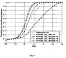
- the differential correlation (used to detect the repetitive synchronization signal from Document 1) shows rather bad performances at high frequency errors, as it can be seen in Fig. 5 , where the timing acquisition performances of the signals from Fig. 3 are evaluated with the tolerance zone of 2 samples.
- pseudo-noise sequences are, for example, the sets of orthogonal Golay (binary) complementary sequences, see M. J. E. Golay, "Complementary Series", IRE Transactions on Information Theory, Vol. IT-7, pp. 82-87, Apr. 1961 (this paper is called Document 8 hereinafter).
- the pairs of complementary Golay sequences exist for even sequence lengths L , and are distinguished by the property that the sum of the aperiodic autocorrelation functions of the sequences equals zero for all non-zero delays.
- a set of orthogonal Golay sequences of length L can be obtained by the bit-wise multiplication of a single Golay complementary sequence of length L with all L Walsh sequences of length L [Document 8].
- the sequences within such a set can be grouped into L /2 different complementary pairs.
- Information embedding in this scenario can for instance be accomplished by labelling each of the orthogonal Golay sequences in the present set. After receiving the signal and demodulating the data from the OFDM signal, the specific sequence could be identified by correlating with all sequences in the present set. Such a bank of correlators can be efficiently implemented, for example, by using the fast Hadamard transformation. Differential encoding might be applied to the demodulated sequence before correlation to remove the channel distortion. In that case the reference sequences used for correlation should be also differentially encoded.
- the present invention also provides a radio communication system, which for instance could consist of base station(s) 120 of a cellular system 100 and terminal(s) 130 communicating with said base station(s).
- the base station(s) and/or terminal(s) would include at least one transmitter unit with means for generating and sending a signal with a centrally symmetric part, s ( k ), wherein said centrally symmetric part s(k) is of arbitrary length N.
- the base station(s) and/or terminal(s) would also include at least one receiver unit including means for receiving and processing signals generated by the transmitter unit.
- the present invention can be used in all applications where synchronization signals are transmitted to support and alleviate timing acquisition in a receiver and also when the signals are carrying some information, such as a transmitter's identification number, etc.
- One of such applications is cell search procedure in the cellular systems.
- the proposed centrally symmetric synchronization signals can be of OFDM type, which brings certain benefits for the demodulation of the information from the signal which has passed multi-path (time-dispersive) propagation channel.
- the noise-like centrally symmetric synchronization signals of other types such as direct-sequence spread-spectrum signals, detected by the reverse differential correlation, can also be deployed with the similar timing acquisition performances.
Landscapes
- Engineering & Computer Science (AREA)
- Signal Processing (AREA)
- Computer Networks & Wireless Communication (AREA)
- Synchronisation In Digital Transmission Systems (AREA)
- Mobile Radio Communication Systems (AREA)
- Transmitters (AREA)
- Radar Systems Or Details Thereof (AREA)
- Reduction Or Emphasis Of Bandwidth Of Signals (AREA)
Abstract
Description
- The present invention relates to a method for synchronization and information transmission in a communication system, and more particularly to a radio communication system and a transmitter unit.
- Several different proposals for the EUTRA synchronization channel (SCH), intended for use in the cell search procedure are proposed in the 3rd Generation Partnership Project RAN1 until now. For instance: Motorola, "Cell Search and Initial Acquisition for OFDM Downlink", R1-051329, Seoul, Korea, Nov.7-11, 2005 (this paper is called
Document 1 hereinafter). - Compared to the solution existing in the WCDMA standard, Motorola's proposal makes a step forward towards concurrent initial timing acquisition and cell identification. In this way, the duration of overall cell search procedure, resulting in complete timing acquisition and cell identification, is supposed to be shortened.
- According to this proposal, the synchronization channel consists of two concatenated identical cell-specific OFDM waveforms, which are preceded by a cyclic prefix of LCP samples (identical to the last LCP samples of the OFDM wavefonn). Such SCH is designed to support the initial timing acquisition by using blind differential correlation detection in the receiver, see: T.M.Schmidl and D.C.Cox, "Robust Frequency and Timing Synchronization for OFDM", IEEE Trans. On Communications, Vol. 45, pp. 1613-1621, Dec. 1997 (this paper is called
Document 5 hereinafter). - The cell identification is performed after the initial timing acquisition, by detecting the cell specific OFDM waveform obtained by modulating the sub-carriers with the elements of a cell-specific Zadoff-Chu sequence of prime length (the Zadoff-Chu sequences are the basis for the generation of a much broader family of so-called GCL sequences, see: B. M. Popovic, "Generalized chirp-like polyphase sequences with optimum correlation properties", IEEE Trans. On Information Theory, vol. 38, pp.1406-1409, July 1992. (this paper is called Document 6 hereinafter). The cell-specific index of the GCL sequence can be detected by using an Inverse Discrete Fourier Transform (IDFT), after the differential encoding of the block of the received signal samples.
- Although the above solution for the synchronization channel seems quite promising in terms of reduced overall cell search time, still its timing acquisition is very sensitive to noise/interference due to the broad triangular shape of the differential correlation function.
- The SCH signal from
Document 1 consists of a cyclic prefix followed by a synchronization signal s(k), k=0,1,..., N-1, consisting of twice repeated basic cell-specific OFDM waveform W(l), l=0,1,...,N/2-1, where N is the number of samples in the OFDM signal obtained after the IDFT in the transmitter. The timing of the SCH can be detected in the receiver by the following algorithm: - A) Take a block of N received signal samples;
- B) Correlate the first N/2 samples of the block with the complex conjugate of the last N/2 samples of the block, and store the resulting differential correlation;
- C) Repeat the first two steps for a new block of N samples of the received signal, taken after a delay of one sample compared to the previous block;
- D) Find the delay of the block of N samples that result in the maximum correlation magnitude, and select it as the initial timing for OFDM symbol demodulation.
- The differential correlation C(p) of the received signal r(k), k=0,1,...,N-1, can be mathematically represented as


- The differential correlation function of the synchronization signal from
Document 1, generated by IFFT of N=128 samples, with cyclic prefix of 10 samples, is shown inFig.1 . - The formula (2) explains the broad triangular-like shape of the differential correlation function in
Fig.1 . Small distortions of the triangular shape come from the fluctuations of the signal envelope. Thus, it can be seen from (2) that the differential correlation depends just on the envelope of synchronization signal, so the different synchronization signals with the constant envelope will produce the same differential correlation. The differential correlation function inFig. 1 reaches a plateau which has a length equal to the length of the cyclic prefix (Document 5). - The peak detection of the differential correlation can be done, for example by finding the maximum of the correlation function calculated in a (10 ms) frame of the received samples. However, there might be synchronization signals from multiple cells that can be received concurrently in the user equipment (UE), and all of them should be detected in the cell search procedure. Consequently, the peak detection of the differential correlation in a frame of received samples is not enough, because it can not discriminate the peaks coming from the different cells.
- Instead, or additionally, some kind of threshold-based selection has to be applied. For example, the magnitude of each differential correlation value can be compared with an adaptive threshold proportional to the energy of the signal in the correlation window of N/2 samples used to calculate the observed correlation value, so all the correlation values larger than a certain percentage of the signal energy in the corresponding correlation window will be selected for further processing by peak detection to find the accurate time of arrival of each synchronization signal.
- The comparison with the above adaptive threshold is equivalent to comparing the normalized differential correlation as defined in
Document 5, eq. (8) (normalized with the received energy in the second half-symbol) with a fixed threshold between 0 and 1. As the timing acquisition performances are basically determined by the properties of differential correlation, we shall not discuss further normalization with the signal energy. - Much better timing acquisition properties would have been obtained if the differential correlation function would have had an impulse-like shape, similar to the aperiodic autocorrelation function of the pseudo random signals, with a narrow central correlation peak corresponding to zero delay, and low correlation sidelobes for other delays.
- An impulse-like differential correlation function is obtained by the OFDM synchronization signal proposed in B. Park et al, "A Novel Timing Estimation Method for OFDM Systems", IEEE Communications Letters, Vol. 7, No.5, pp. 239-241, May 2003 (this paper is called Document 7 hereinafter), eq.(10) as


- The signal (3) is explicitly and exclusively defined as an OFDM signal, to be generated by the IFFT, so the Document 7 does not anticipate other types of centrally symmetric synchronization signals, such as spread-spectrum direct sequence signals.
- If we neglect the complex conjugation in the signal (3), we can notice that it is basically a repetitive signal, whose basic repeated waveform of length N/2 samples is centrally symmetric. Such a signal has an impulse-like differential correlation function, but its repetitive structure results in high correlation sidelobes, equal always to the quarter of the signal energy, regardless of the properties of the pseudo-noise sequences used to modulate the sub-carriers within the OFDM signal. The high correlation sidelobes can cause an increased probability of false timing acquisition, so it is desirable to reduce them as much as possible.
- Besides, the shorter length {N/2) of the basic waveform repeated in the synchronization signal (3) implies a smaller number of different synchronization signals that can be generated. In the application of interest, such as the cell search in a cellular system (which is not considered in Document 7), where the synchronization signals should not just serve for timing acquisition, but also for the information transmission, the smaller number of potential different synchronization signals with low crosscorrelation implies a smaller amount information that can be conveyed by the synchronization signal.
- Further on, the complex conjugation of the basic repeated waveform in the second half of the signal might complicate the implementation of the signal generator and demodulator, especially if the signal is supposed to be obtained by the IDFT of a complex pseudo-noise sequence.
- Also, the centrally symmetric part of the synchronization signal (3) consists of two symmetric waveforms, so N/2 is an even number. However, in some situations it might be desirable to have a single centrally symmetric waveform of an odd length N/2, which may be repeated a number of times in the synchronization signal.
- In the paper, Zhang et al. "Joint Frame Synchronization and Frequency Offset Estimation OFDM Systems" IEEE Trans. on Broadcasting, vol. 51, no 3, September 2005, is described a joint frame synchronization and carrier frequency offset estimation scheme. The paper seems mainly be concentrating on improving the frequency error estimation; it is not said how the arrival time of the training symbol should exactly be estimated.
- The document JIN-WOO LEE ET AL: "Rapid cell search in OFDM-based cellular systems" VEHICULAR TECHNOLOGY CONFERENCE, 2005. VTC 2005-SPRING. 2005 IEEE 61 ST, IEEE, PISCATAWAY, NJ, USA, vol. 2, 30 May 2005 (2005-05-30), pages 1273-1277, XP010855616 ISBN: 978-0-7803-8887-1 discloses a method of synchronization within a communication system wherein from the transmitting side a synchronization signal having a preamble is transmitted. The preamble comprises four repetitive signals of period Np with a guard interval Ng. This document represents the closest prior art.
- A method and a system for synchronizing signals within a communication system is also disclosed in
documents EP 0 915 597 A1 andEP 1 126 673 A2 - It is an object of the present invention to propose a solution for or a reduction of one or more of the problems of the prior art. A primary object is consequently to propose a method which enables synchronization of a communication system with decreased sensitivity to noise/interference, and which also enables a simultaneous transfer of information. These objects are achieved by the appended claim set.
- Thus, according to the invention a signal for improving synchronization in a communication system is generated with a centrally symmetric part, s(k), the centrally symmetric part s(k) being centrally symmetric in the shape of the absolute value thereof, wherein the centrally symmetric part s(k) is of arbitrary length N and is based on a uniquely identifiable sequence c(l) from a set of sequences. According to the invention, the signal is sent over a communication channel and is then received, whereupon a reverse differential correlation D(p) from a block of N received signal samples r(k), k=0,1,...,N-1 is calculated and stored. This is repeated for a new block of N samples of the received signal, taken after a delay of one sample compared to the previous block, a number of times, in order to find the delay of the block of N samples that result in a maximum correlation magnitude, and select such a delay as the initial timing for demodulation, then the unique sequence c(l) from the set of sequences is detected, and thereby the information transmitted is extracted.
- The method of the present invention as defined in
claim 1 could be implemented through a transmitter unit and in a receiver unit in a communication system. Together they would form part of a radio communication system as defined in claim 12 that would include at least one transmitter unit and at least one receiver unit. The transmitter unit and the receiver unit are implemented as follows. - A transmitter unit (120) as defined in claim 11 used in a communication system for improving synchronization and information transmission, is configured to generate a signal with a time symmetric property exploitable for synchronization and a centrally symmetric part, s(k), wherein the signal is based on a uniquely identifiable sequence c(l) from a set of sequences, the centrally symmetric part s(k) is symmetric in the shape of the absolute value thereof, and the centrally symmetric part s(k) is of arbitrary length N, and send the signal over a communication channel.
- A receiver unit (130), used in a communication system for improving synchronization and information transmission, is configured to receive a signal with a time symmetric property exploitable for synchronization, wherein the signal is based on a uniquely identifiable sequence c(l) from a set of sequences, calculate and store a correlation from a block of N received signal samples, calculate and store the reverse differential correlation.
- D(p) from a block of N received signal samples r(k), k = 0,1, ..., N-1, repeat the previous step for a new block of N samples of the received signal, taken after a delay of one sample compared to the previous block, a number of times, find the delay of the block of N samples that result in a maximum correlation magnitude and select such a delay as the initial timing for demodulation, and detect the unique sequence c(l) from the set of sequences.
- The invention significantly improves the performances of the timing acquisition in the receiver in applications where the synchronization signals transmitted to support and alleviate the timing acquisition in the receiver should also carry some information, such as transmitter's identification number, etc. One of such applications is cell search procedure in a cellular system. Besides, it allows an increased amount of information to be carried by the synchronization signals, compared to the prior art in
Document 1. - Additional features and advantages of the present invention will be apparent from the following description.
- Embodiments exemplifying the invention are described, with reference of the appended drawings, in which
- Fig. 1
- illustrates a correlation function according to the prior art;
- Fig. 2
- illustrates a reverse correlation function;
- Fig. 3 to Fig. 6
- are graphs showing various probabilities for correct timing acquisition; and
- Fig. 7
- illustrates a radio communication system according to an embodiment of the present invention.
- In order to achieve an impulse-like differential correlation function, we shall first modify the definition of the differential correlation so that as many as possible different products of samples are involved in the summations corresponding to the different delays. In this way the differential correlation values corresponding to different out-of-synchronization delays will be randomized.
- One way to achieve the random out-of-sync differential correlation values is to reverse the order of samples in one of the blocks of samples used in (1). We shall define so-called reverse differential correlation D(p) as

- To obtain the maximum possible correlation value (5) at p=0, equal to the energy of the signal in the correlation window of ┌N/2┐ samples, the synchronization signal s(k), k=0,1,...,N-1, should be centrally symmetric, i.e. such that

- From (5) and (6) it follows that the reverse differential correlation Ds (p) of the synchronization signal s(k) exists only for p= 0,±1,t2,...,±(┌N/2┐-1), and is given by

- The formula (7) resembles very much to the aperiodic autocorrelation function R(p) of the synchronization signal s(k), defined as

- As it can be seen, the only difference between Ds (p) and R(p) is in a reduced number of summation elements. Thus if the s(k) has an impulse-like aperiodic autocorrelation function, its reverse differential correlation function has very good chances to be impulse-like as well.
- The equation (7) shows that, in general, the non-repetitive, but centrally symmetric pseudo-random signals produce lower correlation sidelobes than the repetitive signals.
- An alternative to centrally symmetrical synchronization signals defined by (6) are such satisfying


- The OFDM synchronization signal (3) proposed in the prior art, Document 7, eq.(10) can be viewed as a special case of signal (9). Note that (9) is more general because it is defined for arbitrary length N, while (3) is defined only for N=0 mod 4.
- The same maximum absolute value of the reverse differential correlation can be obtained if the signal is skew-symmetric, i.e. defined as

- Similarly, the absolute value of (10) will not change if the signal is defined as

- To illustrate the design of centrally symmetric synchronization signals (6) and the properties of the corresponding reverse differential correlation functions (5), we shall generate the set of OFDM centrally symmetric synchronization signals starting from the assumptions given in Document 1: the sampling frequency is 1.92MHz, the sub-carrier spacing is 15kHz, the maximum number of occupied sub-carriers is Nosc=76 out of totally N=128 sub-carriers within 1.92MHz frequency band (the transmission bandwidth is 1.25MHz). The occupied sub-carriers are modulated by the elements of a pseudo-random sequence from the set of sequences with good cross-correlation properties. The different sequences from the set are labelled by the different cell identification numbers (IDs). After the DFT demodulation of the received OFDM signal the transmitted sequence can be identified by de-mapping from the sub-carriers, followed by a certain signal processing. Low cross-correlation between sequences contributes to more reliable identification of the sequences when multiple signals are concurrently received from different cells.
- The output OFDM synchronization signal s(k) of length N=128 samples is obtained by the IDFT of the spectrum H(n) of N=128 Fourier coefficients, as

- If H(n)=H(N-n), n=0,1,2,...,N-1, where H(N)=H(0) holds according to the periodicity of the DFT, it can be shown that the s(k) will be also symmetric around its s(N/2) sample, i.e.

- Starting from the definition of s(k) as


- The spectrum H(n) might be obtained by using the elements of a pseudo-random sequence c(l), l=0, 1,..., L-1, L≤Nosc, as the Fourier coefficients at the occupied sub-carrier frequencies.
- If we define the mapping between c(l) and H(n) as

- Consequently, the resulting synchronization signal s(k), k=0,1,2,...,N-1, is a low-pass base-band OFDM signal symmetrical around its s(N/2) sample, meaning that only the sample s(0) does not have its symmetrical counterpart with respect to s(N/2). In other words, the resulting OFDM synchronization signal can be considered as consisting of two parts: the first part contains one sample and the second part contains N-1 centrally symmetric samples, such that s(k) =s(N-k), k=1,2,...,N-1.
- It further means that for the blind detection of the above OFDM signal we should use the blocks of N-1 input signal samples, and perform the reversed differential correlation as

- However, the whole block of N samples should be used for OFDM demodulation, and subsequent identification of the information content (cell ID), once the correct timing is acquired.
- The remaining question is which kind of centrally symmetric sequences of odd length L to choose for modulation of the sub-carriers. The L-1 pseudo-noise sequences {ar (l)}, r=1,...,L-1, where L is a prime number, used in
Document 1 to produce the repetitive OFDM synchronization signals are Zadoff-Chu (ZC) sequences of odd length L, defined as

- If L is odd, it can be easily shown that the ZC sequence (15)is centrally symmetric (around its (L-1)/2+1-th element), i.e. ar (l)= ar (L-1-l), l=0, 1,..., L-1. To accommodate the sequence length to be equal or less than the maximum number of occupied sub-carriers, we can discard a certain number of sequence elements at the beginning and at the end of the ZC sequence so that the resulting shortened sequence remains centrally symmetrical.
- As the maximum allowed number of occupied sub-carriers is Nosc=76, and the ZC sequence length should be a prime number, we shall use L=79 in (15) to generate a prototype ZC sequence, which is then shortened to length L=75 by discarding the first 2 and the last 2 elements of the prototype ZC sequence, so that the resulting shortened ZC sequence remains centrally symmetric. The shortened sequence is then used in (13) to produce the OFDM synchronization signal (11) after IDFT of H(n).
- By choosing the different values of r in (15), we can obtain up to M=L-1=74 different OFDM synchronization signals, each carrying the different information about the cell ID. This number of cell IDs is almost twice larger than the number (41) of cell IDs in
Document 1 for the same size of synchronization signals. In the same time, the principle of the detection of the ZC sequences fromDocument 1, by using differential encoding and IDFT, can be applied also in the example at hand. - To ensure the demodulation robustness in the case of a multipath propagation channel, the OFDM synchronization signal is preceded by a cyclic prefix. The magnitude of the reverse differential correlation function of the OFDM synchronization signal (11) obtained from the shortened ZC sequence of length L=75, with the cell ID=r=29 and with the cyclic prefix of LCP =10 samples, is shown in
Fig.2 . - The cyclic prefix makes the reverse differential correlation function asymmetrical, with slightly increased sidelobe levels for the negative delays. However, as the sidelobe levels are still relatively low compared to the main peak, the probability of the false timing acquisition is not expected to be influenced by them.
- The Zadoff-Chu sequences are the basis for the generation of the GCL sequences {c(l)}, defined as [6]

- In the user equipment (UE) in cellular systems the initial frequency error (immediately after power on) of the RF signal might be of the order of tens of thousands of Hz. This frequency error will be reduced within the limits of several hundreds of Hz once the receiver is locked to the received signal from a base station. The UE will be locked to a base station after the initial cell search, the task performed by the UE after it is switched on. Once the UE has found its "camping" cell, the cell search procedure enters the monitoring mode, where it monitors the available neighbouring cells, either for possible handover, if the UE is in active mode, or for possible cell re-selection (for better signal reception), if the UE is in the idle mode. In the monitoring mode the frequency error between the received signals and the UE's RF signal is significantly reduced because all the cells are tightly frequency synchronised and the UE is already synchronized to one of them.
- Thus, during the initial cell search it should be possible to detect the time-of-arrival of the synchronization signals transmitted from the base station under relatively high frequency error in the receiver.
- The timing acquisition performance of the synchronization signal from the
Embodiment 1 is evaluated by simulation, in terms of probability of correct timing acquisition as a function of signal-to-noise ratio (SNR) on Additive White Gaussian Noise (AWGN) channel. The four values of the initial frequency error df between the UE and the base station are simulated: df=0, 1, 2 and 3 ppm at 2.6GHz carrier frequency. The cyclic prefix is 10 samples long in all cases. - The timing acquisition is considered correct if the estimated time of arrival is within the error tolerance zone, which is positioned before the true timing position, so that it overlaps the cyclic prefix in the OFDM signal. The size of the error tolerance zone cannot be larger than the length of the cyclic prefix, and should be equal to the part of the cyclic prefix that is not covered by the channel response of the previous OFDM symbol. As the length of cyclic prefix should not be much longer (if at all) than the maximum expected length of the channel response, the error tolerance zone in practice cannot be longer than a few samples. However, as the repetitive synchronization signal from
Document 1 is evaluated as the reference for comparison, we shall take the error tolerance zone to be equal to the cyclic prefix, in order to obtain the best performances for the signal fromDocument 1. - It can be easily known that the magnitude of the differential correlation does not depend on the frequency error, so the signal from
Document 1 is evaluated with no frequency error. The results are shown inFig.3 . - Without the initial frequency error, the centrally symmetric signal detected by the reverse differential correlation outperforms the repetitive signal detected by the differential correlation by more than 1dB at 0.5 probability of correct acquisition, and more than 5dB at 0.9 probability of correct acquisition.
- For the non-zero values of the frequency error, the performance of the repetitive signal remains unchanged, while the performance of the centrally symmetric signal deteriorates with increase of the frequency error. At the frequency error of 1 ppm (2600Hz), the relative performances remain almost unchanged. At the frequency error of 2 ppm, the centrally symmetric signal still remains better at probabilities of correct acquisition above 0.5, although the repetitive signal became better at very low SNRs. However, at the frequency error of 3 ppm the centrally symmetric signal fails to acquire the timing synchronization regardless of the SNR. This is because some of the sidelobes of the reverse differential correlation become higher than the main lobe, even without the presence of noise.
- The timing acquisition performance results for the signals from
Embodiment 1 has demonstrated that if the frequency error is above a certain threshold, the differential correlation produces better timing acquisition than the reverse differential correlation, while below a certain frequency error it is opposite. - This result suggests that if the frequency error during the initial cell search is above 2 ppm, it would be beneficial that the synchronization signal is both centrally symmetric and periodic. Such a signal could be detected in the UE both by the differential correlation and the reverse differential correlation, depending on UE's cell search mode, i.e. depending on the maximum expected frequency error in between the carrier frequency of received signal and the frequency of the reference RF signal in the receiver.
- Thus, the initial cell search the synchronization signals transmitted from the base stations should be performed by using the differential correlation. Once the cell search enter the monitoring mode, the synchronization signals can be detected by the reverse differential correlation, which provide much better timing acquisition performances if the frequency error is low, allowing a faster detection of the neighbouring cells. It should be noted that in the cell search monitoring mode a quick detection of the neighbouring cells with better signal quality reduces the interference in the system because it allows UE to transmit will lower power.
- Assuming the same conditions as in
Embodiment 1, the set of centrally symmetric and periodic OFDM synchronization signals can be generated from the set of 36 ZC sequences of prime length L=37, by using the mapping (13), and IDFT (11), where N=64. The signal of length 64 samples obtained by (11) is then periodically extended, i.e. repeated to produce the final centrally symmetric and periodic synchronization signal of length 128 samples. As in the previous example, in the resulting signal s(k) of length N=128 samples, only the sample s(0) does not have its symmetrical counterpart with respect to s(N/2). - The same signal can be obtained directly (without periodic extension) by using (11) and the following general mapping

- The timing acquisition performance of the above synchronization signal is evaluated by simulation, in terms of probability of correct timing acquisition as a function of signal-to-noise ratio (SNR) on Additive White Gaussian Noise (AWGN) channel. The four values of the initial frequency error df between the UE and the base station are simulated: df=0, 1, 2 and 3 ppm at 2.6 GHz carrier frequency. The cyclic prefix is 10 samples long in all cases. The results are shown in
Fig.4 . - From
Fig. 3 andFig. 4 it can be seen that the reverse differential correlation of centrally symmetric and periodic OFDM signal is more robust to the frequency error of 3 ppm than the reverse differential correlation function of the non-periodic OFDM signal. Starting from the similarity between the formulas (7) and (8), the explanation of the different timing acquisition performances inFig. 3 andFig. 4 can be derived from the properties of the generalized aperiodic autocorrelation functions of the corresponding signals, widely known as the ambiguity function. This function is a two-dimensional function of the delay and the frequency error. - It is well known that the chirp-like signals, such as the non-repetitive signal from
Fig. 3 , have the ridge-type ambiguity function, distinguished by a shifted, non-zero delay position of its main lobe at a high frequency error. This effect is the major reason for the collapse of the reverse differential correlation at a 3 ppm frequency error. The signals with some other cell IDs might be a bit less sensitive to this effect and might converge to a probability of acquisition equal to 1 at higher SNRs, but they will also collapse at frequency errors, which are a bit higher. - On the other side, the periodic signals, such as the one from
Fig. 4 , have so-called bed-of-nails type ambiguity functions, distinguished by rather high sidelobes regularly placed in the time-frequency plane, but the position of the main lobe, corresponding to the zero delay is unchanged with the frequency. Basically, these signals behave as virtually having the shorter length, which results in less distortion at high frequency errors. On the other side, the high sidelobes of the reverse differential correlation come from the repetitive nature of the signal, so that even when there is no frequency error, the signal consisting of two periods of the same basic waveform has the reverse differential correlation sidelobes equal at least to the half of the main lobe. This results in a loss of acquisition performances for low frequency errors (below 2 ppm), as it can be noticed by comparingFig. 3 andFig. 4 . - As abovementioned, the error tolerance zone in practice cannot be longer than a few samples. In that case, however, even the differential correlation (used to detect the repetitive synchronization signal from Document 1) shows rather bad performances at high frequency errors, as it can be seen in
Fig. 5 , where the timing acquisition performances of the signals fromFig. 3 are evaluated with the tolerance zone of 2 samples. - The reason for bad performances of the differential correlation lies in the plateau shown in
Fig. 1 , which makes it highly probable that the noise will produce a correlation peak at the delay within the correlation plateau less than the zero (correct) delay. Thus, the curve corresponding to repetitive signal converges very slowly to thevalue 1 with an increase of SNR. - The previous discussion about the different types of the ambiguity functions leads to consideration of other types of the pseudo-noise sequences, with ambiguity functions more tolerant to frequency errors. Such pseudo-noise sequences are, for example, the sets of orthogonal Golay (binary) complementary sequences, see M. J. E. Golay, "Complementary Series", IRE Transactions on Information Theory, Vol. IT-7, pp. 82-87, Apr. 1961 (this paper is called Document 8 hereinafter). The pairs of complementary Golay sequences exist for even sequence lengths L, and are distinguished by the property that the sum of the aperiodic autocorrelation functions of the sequences equals zero for all non-zero delays. A set of orthogonal Golay sequences of length L can be obtained by the bit-wise multiplication of a single Golay complementary sequence of length L with all L Walsh sequences of length L [Document 8]. The sequences within such a set can be grouped into L/2 different complementary pairs.
- If the bits of a Golay sequence from the set of orthogonal Golay complementary pairs are used as the Fourier coefficients H(n) in (11), the resulting OFDM synchronization signal s(k) is similar to (9) and has the property:

- Such a signal can be detected by a modified reversed differential correlation (10), as

- It can be easily known that the magnitudes of the reversed differential correlations (10) and (19) remain unchanged under arbitrary frequency error in the signal received over a single-path propagation channel. This is a general property that is valid for arbitrary signals (9), (9.1) and (18).
- If the elements of a Golay sequence c(k) are mapped as the Fourier coefficients of the equidistant consecutive sub-carriers, for example as

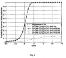
- The timing acquisition performances of an OFDM signal obtained from a Golay complementary sequence of length L=64 mapped according to (20) and (11) into an OFDM signal of length N=128, are shown in
Fig. 6 . It can be seen that the timing acquisition performances of the OFDM signal obtained from a Golay complementary sequence do not change with the increase of the frequency error. - Information embedding in this scenario can for instance be accomplished by labelling each of the orthogonal Golay sequences in the present set. After receiving the signal and demodulating the data from the OFDM signal, the specific sequence could be identified by correlating with all sequences in the present set. Such a bank of correlators can be efficiently implemented, for example, by using the fast Hadamard transformation. Differential encoding might be applied to the demodulated sequence before correlation to remove the channel distortion. In that case the reference sequences used for correlation should be also differentially encoded.
- Now with reference to
Fig. 7 , the present invention also provides a radio communication system, which for instance could consist of base station(s) 120 of acellular system 100 and terminal(s) 130 communicating with said base station(s). The base station(s) and/or terminal(s) would include at least one transmitter unit with means for generating and sending a signal with a centrally symmetric part, s(k), wherein said centrally symmetric part s(k) is of arbitrary length N. The base station(s) and/or terminal(s) would also include at least one receiver unit including means for receiving and processing signals generated by the transmitter unit. - The present invention can be used in all applications where synchronization signals are transmitted to support and alleviate timing acquisition in a receiver and also when the signals are carrying some information, such as a transmitter's identification number, etc. One of such applications is cell search procedure in the cellular systems.
- The proposed centrally symmetric synchronization signals can be of OFDM type, which brings certain benefits for the demodulation of the information from the signal which has passed multi-path (time-dispersive) propagation channel.
- However, the noise-like centrally symmetric synchronization signals of other types, such as direct-sequence spread-spectrum signals, detected by the reverse differential correlation, can also be deployed with the similar timing acquisition performances.
Claims (12)
- A method of synchronization in a communication system, characterised by the steps of
generating a signal with a time symmetric property exploitable for synchronization, wherein the signal is based on a uniquely identifiable sequence c(l) from a set of sequences;
sending the signal over a communication channel; and,
in the step of generating the signal, generating the signal with a centrally symmetric part, s(k), wherein the centrally symmetric part s(k) is centrally symmetric in the shape of the absolute value, and the centrally symmetric part s(k) is of arbitrary length N;- comprising generating the signal such that s(k) is obtained as the IDFT of the spectrum H(n) of N sub-carrier weights, the spectrum H(n) being generated by using the elements of a sequence c(l), l=0, 1,..., L-1, L≤Nosc , as the Fourier coefficients at the occupied sub-carrier frequencies, Nosc being the maximum number of occupied sub-carriers;- comprising generating the signal such that s(k) is obtained as the IDFT of the spectrum H(n) of N sub-carrier weights, such that H(n)=H(N-n), n=0,1,2,...,N-1, where H(N)=H(0) holds according to the periodicity of the DFT, andcomprising mapping the sequence c(l) on to the spectrum H(n) as
- The method according to claim 1, comprising:receiving the signal;calculating and storing a correlation from a block of N received signal samples;repeating the previous step for a new block of N samples of the received signal, taken after a delay of one sample compared to the previous block, a number of times;finding the delay of the block of N samples that result in a maximum correlation magnitude, and selecting such a delay as the initial timing for demodulation;detecting the unique sequence c(l) from the set of sequences and thereby extracting the information transmitted,in the step of calculating and storing a correlation, calculating and storing the reverse differential correlation D(p) from a block of N received signal samples r(k), k=0,1,...,N-1.
- The method according to claims 1 or 2, comprising generating the signal such that the centrally symmetry of the shape of the absolute value of the centrally symmetric part s(k) is due to the centrally symmetric part s(k) being

- The method according to any of claims 1 to 3, comprising generating the signal such that N is an even positive integer, and where s(k) is also periodic with period N/2, i.e. such that s(k)= s(k+Nl2).
- The method according to any of claims 1 to 4, comprising generating the signal such that s(k) is preceded by a cyclic prefix of LCP samples, identical to the last LCP samples of s(k).
- The method according to claim 1, comprising using a sequence c(l) that is pseudo-random.
- The method according to claim 6, wherein the sequence c(l) is a Zadoff-Chu sequence defined as


or, the sequence c(l) is a Generalized Chirp-Like (GCL) sequence defined as
- The method according to any of claims 1 to 7, comprising

- The method according to any of claims 4 to 8, comprising
using differential correlation under relatively high frequency error in the received signal,
using the reverse differential correlation under relatively low frequency error in the received signal. - The method according to any of claims 1 to 9, comprising mapping the sequence c(l) to the identity of a sender of the signal s(k), and/or using a sequence c(l) that is binary.
- A transmitter unit (120), for use in a communication system, characterised in that the transmitter unit (120) is:configured to generate a signal with a time symmetric property exploitable for synchronization and a centrally symmetric part, s(k), wherein the signal is based on a uniquely identifiable sequence c(l) from a set of sequences, the centrally symmetric part s(k) is centrally symmetric in the shape of the absolute value thereof, and the centrally symmetric part s(k) is of arbitrary length N, andconfigured to send the signal over a communication channel;wherein the transmitter unit (120) is configured to generate the signal such that s(k) is obtained as the IDFT of the spectrum H(n) of N sub-carrier weights, the spectrum H(n) being generated by using the elements of a sequence c(l), l=0, 1,.... L-1, L≤Nosc, as the Fourier coefficients at the occupied sub-carrier frequencies, Nosc being the maximum number of occupied sub-carriers; andwherein the transmitter unit (120) is configured to generate the signal such that s(k) is obtained as the IDFT of the spectrum H(n) of N sub-carrier weights, such that H(n)=H(N-n), n=0,1,2,...,N-1, where H(N)=H(0) holds according to the periodicity of the DFT, andwherein the transmitter is configured to map the sequence c(l) on to the spectrum H(n) as

- A radio communication system (100), including at least one transmitter unit (120) according to claim 11, and at least one receiver unit (130), for use in the communication system, characterised in that the receiver unit (130) is:configured to receive a signal with a time symmetric property exploitable for synchronization, and wherein the signal is based on a uniquely identifiable sequence c(l) from a set of sequences,configured to calculate and store a correlation from a block of N received signal samples,and calculate and store the reverse differential correlation D(p) from a block of N received signal samples r(k), k=0,1,...,N-1,configured to repeat the previous step for a new block of N samples of the received signal, taken after a delay of one sample compared to the previous block, a number of times,configured to find the delay of the block of N samples that result in a maximum correlation magnitude, and for selecting such a delay as the initial timing for demodulation,configured to detect the unique sequence c(l) from the set of sequences.
Applications Claiming Priority (1)
| Application Number | Priority Date | Filing Date | Title |
|---|---|---|---|
| PCT/CN2006/000076 WO2007082408A1 (en) | 2006-01-18 | 2006-01-18 | Method for improved synchronization and information transmission in a communication system |
Publications (4)
| Publication Number | Publication Date |
|---|---|
| EP1980030A1 EP1980030A1 (en) | 2008-10-15 |
| EP1980030A4 EP1980030A4 (en) | 2009-08-19 |
| EP1980030B1 EP1980030B1 (en) | 2010-08-25 |
| EP1980030B2 true EP1980030B2 (en) | 2017-08-09 |
Family
ID=38287230
Family Applications (1)
| Application Number | Title | Priority Date | Filing Date |
|---|---|---|---|
| EP06705497.3A Active EP1980030B2 (en) | 2006-01-18 | 2006-01-18 | Method for improved synchronization and information transmission in a communication system |
Country Status (9)
| Country | Link |
|---|---|
| US (5) | US8139663B2 (en) |
| EP (1) | EP1980030B2 (en) |
| JP (1) | JP4976420B2 (en) |
| CN (1) | CN101233701B (en) |
| AT (1) | ATE479241T1 (en) |
| DE (1) | DE602006016492D1 (en) |
| ES (1) | ES2349148T5 (en) |
| PT (1) | PT1980030E (en) |
| WO (1) | WO2007082408A1 (en) |
Families Citing this family (31)
| Publication number | Priority date | Publication date | Assignee | Title |
|---|---|---|---|---|
| ES2349148T5 (en) | 2006-01-18 | 2017-12-19 | Huawei Technologies Co., Ltd. | Method to improve the synchronization and transmission of information in a communication system |
| CN101297486B (en) | 2006-09-25 | 2010-05-19 | 华为技术有限公司 | Information carrying synchronization code and method for frame timing synchronization |
| CN101536379A (en) * | 2006-11-10 | 2009-09-16 | 夏普株式会社 | Wireless communication method, receiving method and wireless communication device |
| GB2458418B (en) | 2006-12-19 | 2011-08-03 | Lg Electronics Inc | Sequence generating method for efficient detection and method for transmitting and receiving signals using the same |
| US20080151980A1 (en) * | 2006-12-22 | 2008-06-26 | Bengt Lindoff | Method of and apparatus for adaptive frequency error estimation |
| SI2090050T2 (en) * | 2007-05-02 | 2017-10-30 | Huawei Technologies Co., Ltd. | Method and apparatus of establishing a synchronisation signal in a communication system |
| EP2145420B1 (en) * | 2007-05-17 | 2012-10-17 | LG Electronics Inc. | Method of transmitting synchronization signal in wireless communication system |
| US20080310539A1 (en) * | 2007-06-15 | 2008-12-18 | Kowalski John M | Systems and methods for generating an orthogonal signal from sequences that are not multiples of 2n |
| HUE031920T2 (en) * | 2007-06-18 | 2017-08-28 | Panasonic Ip Corp America | Sequence allocating method, transmitting method and wireless mobile station device |
| KR100938756B1 (en) | 2007-07-06 | 2010-01-26 | 엘지전자 주식회사 | Method for performing cell search procedure in wireless communication system |
| WO2009021382A1 (en) | 2007-08-15 | 2009-02-19 | Huawei Technologies Co., Ltd. | Generation and detection of synchronization signals |
| US7965797B2 (en) | 2007-11-01 | 2011-06-21 | Texas Instruments Incorporated | Method, system and apparatus for generating constant amplitude zero autocorrelation sequences |
| JP5646609B2 (en) * | 2009-05-29 | 2014-12-24 | トムソン ライセンシングThomson Licensing | Method and apparatus for symbol timing recovery |
| JP5612224B2 (en) | 2011-03-14 | 2014-10-22 | エヌイーシー(チャイナ)カンパニー, リミテッドNEC(China)Co.,Ltd. | Primary synchronization signal detection method and apparatus |
| CN106534027B (en) | 2011-09-29 | 2020-05-19 | 广东天讯达资讯科技股份有限公司 | Method for generating synchronization signal for wireless communication system |
| JP5988622B2 (en) * | 2012-03-08 | 2016-09-07 | ホアウェイ・テクノロジーズ・カンパニー・リミテッド | Method for improving synchronization and information transmission in a communication system |
| KR101340048B1 (en) | 2012-06-12 | 2013-12-11 | (주)에프씨아이 | Apparatus and method for detecting spectrum inversion |
| US20150117295A1 (en) * | 2013-10-30 | 2015-04-30 | Electronics And Telecommunications Research Institute | Method and apparatus for device-to-device communication |
| US9615341B2 (en) * | 2013-11-01 | 2017-04-04 | Futurewei Technologies, Inc. | System and method for transmitting a synchronization signal |
| CN110365366B (en) * | 2013-11-01 | 2021-09-03 | 华为技术有限公司 | Transmitter, receiver and method of generating synchronization signal |
| KR102244944B1 (en) * | 2014-04-21 | 2021-04-27 | 삼성전자주식회사 | Transmitting apparatus and receiving apparatus and controlling method thereof |
| TR201810572T4 (en) | 2015-03-06 | 2018-08-27 | Ericsson Telefon Ab L M | Beam creation using an antenna assembly. |
| US20160381652A1 (en) * | 2015-06-24 | 2016-12-29 | Nokia Technologies Oy | Method and apparatus for detection of synchronization signals in wireless networks |
| US10700762B2 (en) | 2016-05-04 | 2020-06-30 | Telefonaktiebolaget Lm Ericsson (Publ) | Beam forming using an antenna arrangement |
| CN107566022B (en) * | 2016-06-30 | 2020-10-23 | 华为技术有限公司 | Beam training sequence design method and device |
| CN105978841A (en) * | 2016-07-04 | 2016-09-28 | 东南大学 | Symbol synchronization method in visible light DCO-OFDM communication system |
| US11855821B2 (en) * | 2016-09-30 | 2023-12-26 | Nec Corporation | Methods and apparatuses for synchronous signal transmission |
| US11030827B2 (en) | 2018-01-12 | 2021-06-08 | Ford Global Technologies, Llc | Method and apparatus for dynamic distributed services redistribution |
| CN112019292B (en) * | 2020-08-14 | 2021-08-03 | 武汉大学 | LTE downlink hybrid timing synchronization method and system |
| CN112422257A (en) * | 2020-11-17 | 2021-02-26 | 上海道生物联技术有限公司 | Method and system for sending synchronization signal |
| CN115174333B (en) * | 2022-07-06 | 2024-03-12 | 上海大学 | Extremely simple signal receiving and transmitting method suitable for URLLC scene |
Family Cites Families (32)
| Publication number | Priority date | Publication date | Assignee | Title |
|---|---|---|---|---|
| EP1720311B1 (en) | 1997-11-05 | 2011-06-01 | Sony Deutschland Gmbh | Synchronisation of digital communication systems |
| US6618452B1 (en) | 1998-06-08 | 2003-09-09 | Telefonaktiebolaget Lm Ericsson (Publ) | Burst carrier frequency synchronization and iterative frequency-domain frame synchronization for OFDM |
| CA2276971A1 (en) | 1999-07-06 | 2001-01-06 | Wen Tong | Preamble using golay sequence for access channel in cellular communications systems |
| US6922388B1 (en) * | 2000-02-11 | 2005-07-26 | Lucent Technologies Inc. | Signal construction, detection and estimation for uplink timing synchronization and access control in a multi-access wireless communication system |
| US6704374B1 (en) * | 2000-02-16 | 2004-03-09 | Thomson Licensing S.A. | Local oscillator frequency correction in an orthogonal frequency division multiplexing system |
| JP2001333043A (en) | 2000-03-15 | 2001-11-30 | Sony Corp | Method and device for data modulation and communication equipment |
| US7106821B2 (en) | 2000-03-15 | 2006-09-12 | Sony Corporation | Data modulation method, data modulation device and communication device |
| KR100377356B1 (en) * | 2000-05-19 | 2003-03-26 | 삼성전자주식회사 | Symbol and/or frequency Synchronization of Orthogonal Frequency Division Multiplexed signals |
| JP3690293B2 (en) | 2001-03-06 | 2005-08-31 | 株式会社日立製作所 | Multi-carrier modulation synchronization method |
| US7706458B2 (en) | 2001-04-24 | 2010-04-27 | Mody Apurva N | Time and frequency synchronization in Multi-Input, Multi-Output (MIMO) systems |
| US6959050B2 (en) | 2001-06-15 | 2005-10-25 | Motorola, Inc. | Method and apparatus for synchronizing an OFDM signal |
| KR100555721B1 (en) | 2001-08-20 | 2006-03-03 | 삼성전자주식회사 | Method for creating Symmetric-Identical preamble and method for synchronizing symbol and frequency of Orthogonal Frequency Division Multiplexed signals by using the Symmetric-Identical preamble |
| US7116745B2 (en) * | 2002-04-17 | 2006-10-03 | Intellon Corporation | Block oriented digital communication system and method |
| KR100866181B1 (en) | 2002-07-30 | 2008-10-30 | 삼성전자주식회사 | The method and apparatus for transmitting/receiving signal in a communication system |
| US7251490B2 (en) | 2003-06-18 | 2007-07-31 | Qualcomm Incorporated | System and method for GSM hard handoff |
| CN1691659B (en) * | 2004-04-23 | 2012-01-18 | 北京三星通信技术研究有限公司 | A method for synchronization in OFDM system |
| CN100389582C (en) | 2004-07-26 | 2008-05-21 | 南京邮电学院 | Synchronous method of orthogonal freuency division multiplex in broadband radio insertion system |
| WO2006015108A2 (en) | 2004-07-27 | 2006-02-09 | Zte San Diego, Inc. | Transmission and reception of reference preamble signals in ofdma or ofdm communication systems |
| JP2006054540A (en) * | 2004-08-10 | 2006-02-23 | Nakayo Telecommun Inc | Synchronization method of communication |
| CN1780276B (en) * | 2004-11-25 | 2012-01-04 | 都科摩(北京)通信技术研究中心有限公司 | Combined time synchronizing and frequency bias evaluation and evaluating device for orthogonal frequency division duplex system |
| KR100688086B1 (en) * | 2004-12-13 | 2007-03-02 | 한국전자통신연구원 | Apparatus and Method for Correlation using Symmetry of Multiplying Coefficients |
| JP4463780B2 (en) * | 2005-06-14 | 2010-05-19 | 株式会社エヌ・ティ・ティ・ドコモ | Transmitting apparatus and transmitting method |
| US8730877B2 (en) * | 2005-06-16 | 2014-05-20 | Qualcomm Incorporated | Pilot and data transmission in a quasi-orthogonal single-carrier frequency division multiple access system |
| CN1889553A (en) | 2005-06-30 | 2007-01-03 | 都科摩(北京)通信技术研究中心有限公司 | Training sequence generating method, communicating system and communicating method |
| CN100362810C (en) | 2005-07-28 | 2008-01-16 | 华为技术有限公司 | Method for implementing fast switching of virtual special LAN service |
| KR101306696B1 (en) * | 2005-11-10 | 2013-09-10 | 엘지전자 주식회사 | apparatus and method for transmitting data using a plurality of carriers |
| EP1955509A4 (en) * | 2005-11-28 | 2011-07-06 | Lg Electronics Inc | Method and apparatus for generating and transmitting code sequence in a wireless communication system |
| USRE44351E1 (en) | 2005-12-20 | 2013-07-09 | Lg Electronics Inc. | Method of generating code sequence and method of transmitting signal using the same |
| US8830983B2 (en) | 2005-12-20 | 2014-09-09 | Lg Electronics Inc. | Method of generating code sequence and method of transmitting signal using the same |
| CN101326739B (en) * | 2006-01-18 | 2011-08-03 | 华为技术有限公司 | Synchronization method and system for mobile communication |
| ES2349148T5 (en) | 2006-01-18 | 2017-12-19 | Huawei Technologies Co., Ltd. | Method to improve the synchronization and transmission of information in a communication system |
| SI2090050T2 (en) | 2007-05-02 | 2017-10-30 | Huawei Technologies Co., Ltd. | Method and apparatus of establishing a synchronisation signal in a communication system |
-
2006
- 2006-01-18 ES ES06705497.3T patent/ES2349148T5/en active Active
- 2006-01-18 WO PCT/CN2006/000076 patent/WO2007082408A1/en active Application Filing
- 2006-01-18 JP JP2008550603A patent/JP4976420B2/en active Active
- 2006-01-18 DE DE602006016492T patent/DE602006016492D1/en active Active
- 2006-01-18 EP EP06705497.3A patent/EP1980030B2/en active Active
- 2006-01-18 AT AT06705497T patent/ATE479241T1/en not_active IP Right Cessation
- 2006-01-18 CN CN200680027974.2A patent/CN101233701B/en active Active
- 2006-01-18 PT PT06705497T patent/PT1980030E/en unknown
-
2008
- 2008-07-18 US US12/175,632 patent/US8139663B2/en active Active
-
2012
- 2012-02-03 US US13/365,957 patent/US9337998B2/en active Active
- 2012-02-03 US US13/365,889 patent/US8867636B2/en active Active
-
2014
- 2014-10-24 US US14/523,478 patent/US9369271B2/en active Active
-
2016
- 2016-05-16 US US15/155,753 patent/US10491369B2/en active Active
Also Published As
| Publication number | Publication date |
|---|---|
| WO2007082408A1 (en) | 2007-07-26 |
| JP4976420B2 (en) | 2012-07-18 |
| US20080310567A1 (en) | 2008-12-18 |
| PT1980030E (en) | 2010-12-02 |
| US8139663B2 (en) | 2012-03-20 |
| CN101233701B (en) | 2015-12-02 |
| EP1980030A1 (en) | 2008-10-15 |
| US8867636B2 (en) | 2014-10-21 |
| US9369271B2 (en) | 2016-06-14 |
| US20150103935A1 (en) | 2015-04-16 |
| CN101233701A (en) | 2008-07-30 |
| ES2349148T3 (en) | 2010-12-28 |
| JP2009524299A (en) | 2009-06-25 |
| US20120134432A1 (en) | 2012-05-31 |
| DE602006016492D1 (en) | 2010-10-07 |
| ATE479241T1 (en) | 2010-09-15 |
| US10491369B2 (en) | 2019-11-26 |
| US9337998B2 (en) | 2016-05-10 |
| ES2349148T5 (en) | 2017-12-19 |
| EP1980030A4 (en) | 2009-08-19 |
| EP1980030B1 (en) | 2010-08-25 |
| US20120134443A1 (en) | 2012-05-31 |
| US20160261402A1 (en) | 2016-09-08 |
Similar Documents
| Publication | Publication Date | Title |
|---|---|---|
| EP1980030B2 (en) | Method for improved synchronization and information transmission in a communication system | |
| US10009928B2 (en) | Method, apparatus and system for random access | |
| EP1974516B1 (en) | Method of generating code sequence and method of transmitting signal using the same | |
| US8254344B2 (en) | Reference sequence construction for fast cell search | |
| US8320360B2 (en) | Method and apparatus for fast cell search | |
| US8830983B2 (en) | Method of generating code sequence and method of transmitting signal using the same | |
| US10135654B2 (en) | Method and apparatus for generating code sequence in a communication system | |
| EP2117147A1 (en) | Transmitting device and receiving device in cellular system | |
| CN102255722A (en) | Method for synchronizing and transmitting information in improved communication system | |
| CN102340475A (en) | Method for improving synchronous and information transmission in communication system | |
| KR20080031111A (en) | Mobile communication system and its signal transfer method | |
| JP5875561B2 (en) | Method for improving synchronization and information transmission in a communication system | |
| JP5988622B2 (en) | Method for improving synchronization and information transmission in a communication system |
Legal Events
| Date | Code | Title | Description |
|---|---|---|---|
| PUAI | Public reference made under article 153(3) epc to a published international application that has entered the european phase |
Free format text: ORIGINAL CODE: 0009012 |
|
| 17P | Request for examination filed |
Effective date: 20080801 |
|
| AK | Designated contracting states |
Kind code of ref document: A1 Designated state(s): AT BE BG CH CY CZ DE DK EE ES FI FR GB GR HU IE IS IT LI LT LU LV MC NL PL PT RO SE SI SK TR |
|
| A4 | Supplementary search report drawn up and despatched |
Effective date: 20090716 |
|
| RIC1 | Information provided on ipc code assigned before grant |
Ipc: H04L 7/04 20060101AFI20090710BHEP Ipc: H04L 27/26 20060101ALI20090710BHEP Ipc: H04B 7/00 20060101ALI20090710BHEP |
|
| GRAP | Despatch of communication of intention to grant a patent |
Free format text: ORIGINAL CODE: EPIDOSNIGR1 |
|
| RIC1 | Information provided on ipc code assigned before grant |
Ipc: H04B 7/00 20060101ALI20100408BHEP Ipc: H04L 7/04 20060101AFI20100408BHEP Ipc: H04L 27/26 20060101ALI20100408BHEP |
|
| DAX | Request for extension of the european patent (deleted) | ||
| GRAS | Grant fee paid |
Free format text: ORIGINAL CODE: EPIDOSNIGR3 |
|
| GRAA | (expected) grant |
Free format text: ORIGINAL CODE: 0009210 |
|
| AK | Designated contracting states |
Kind code of ref document: B1 Designated state(s): AT BE BG CH CY CZ DE DK EE ES FI FR GB GR HU IE IS IT LI LT LU LV MC NL PL PT RO SE SI SK TR |
|
| REG | Reference to a national code |
Ref country code: GB Ref legal event code: FG4D |
|
| REG | Reference to a national code |
Ref country code: CH Ref legal event code: EP |
|
| REG | Reference to a national code |
Ref country code: IE Ref legal event code: FG4D |
|
| REF | Corresponds to: |
Ref document number: 602006016492 Country of ref document: DE Date of ref document: 20101007 Kind code of ref document: P |
|
| REG | Reference to a national code |
Ref country code: PT Ref legal event code: SC4A Free format text: AVAILABILITY OF NATIONAL TRANSLATION Effective date: 20101124 |
|
| REG | Reference to a national code |
Ref country code: SE Ref legal event code: TRGR |
|
| REG | Reference to a national code |
Ref country code: NL Ref legal event code: VDEP Effective date: 20100825 |
|
| REG | Reference to a national code |
Ref country code: ES Ref legal event code: FG2A Effective date: 20101215 |
|
| LTIE | Lt: invalidation of european patent or patent extension |
Effective date: 20100825 |
|
| PG25 | Lapsed in a contracting state [announced via postgrant information from national office to epo] |
Ref country code: FI Free format text: LAPSE BECAUSE OF FAILURE TO SUBMIT A TRANSLATION OF THE DESCRIPTION OR TO PAY THE FEE WITHIN THE PRESCRIBED TIME-LIMIT Effective date: 20100825 Ref country code: AT Free format text: LAPSE BECAUSE OF FAILURE TO SUBMIT A TRANSLATION OF THE DESCRIPTION OR TO PAY THE FEE WITHIN THE PRESCRIBED TIME-LIMIT Effective date: 20100825 Ref country code: LT Free format text: LAPSE BECAUSE OF FAILURE TO SUBMIT A TRANSLATION OF THE DESCRIPTION OR TO PAY THE FEE WITHIN THE PRESCRIBED TIME-LIMIT Effective date: 20100825 |
|
| REG | Reference to a national code |
Ref country code: RO Ref legal event code: EPE |
|
| PG25 | Lapsed in a contracting state [announced via postgrant information from national office to epo] |
Ref country code: SI Free format text: LAPSE BECAUSE OF FAILURE TO SUBMIT A TRANSLATION OF THE DESCRIPTION OR TO PAY THE FEE WITHIN THE PRESCRIBED TIME-LIMIT Effective date: 20100825 Ref country code: PL Free format text: LAPSE BECAUSE OF FAILURE TO SUBMIT A TRANSLATION OF THE DESCRIPTION OR TO PAY THE FEE WITHIN THE PRESCRIBED TIME-LIMIT Effective date: 20100825 Ref country code: CY Free format text: LAPSE BECAUSE OF FAILURE TO SUBMIT A TRANSLATION OF THE DESCRIPTION OR TO PAY THE FEE WITHIN THE PRESCRIBED TIME-LIMIT Effective date: 20100825 Ref country code: IS Free format text: LAPSE BECAUSE OF FAILURE TO SUBMIT A TRANSLATION OF THE DESCRIPTION OR TO PAY THE FEE WITHIN THE PRESCRIBED TIME-LIMIT Effective date: 20101225 Ref country code: BG Free format text: LAPSE BECAUSE OF FAILURE TO SUBMIT A TRANSLATION OF THE DESCRIPTION OR TO PAY THE FEE WITHIN THE PRESCRIBED TIME-LIMIT Effective date: 20101125 |
|
| REG | Reference to a national code |
Ref country code: HU Ref legal event code: AG4A Ref document number: E009380 Country of ref document: HU |
|
| PG25 | Lapsed in a contracting state [announced via postgrant information from national office to epo] |
Ref country code: NL Free format text: LAPSE BECAUSE OF FAILURE TO SUBMIT A TRANSLATION OF THE DESCRIPTION OR TO PAY THE FEE WITHIN THE PRESCRIBED TIME-LIMIT Effective date: 20100825 Ref country code: LV Free format text: LAPSE BECAUSE OF FAILURE TO SUBMIT A TRANSLATION OF THE DESCRIPTION OR TO PAY THE FEE WITHIN THE PRESCRIBED TIME-LIMIT Effective date: 20100825 Ref country code: BE Free format text: LAPSE BECAUSE OF FAILURE TO SUBMIT A TRANSLATION OF THE DESCRIPTION OR TO PAY THE FEE WITHIN THE PRESCRIBED TIME-LIMIT Effective date: 20100825 Ref country code: GR Free format text: LAPSE BECAUSE OF FAILURE TO SUBMIT A TRANSLATION OF THE DESCRIPTION OR TO PAY THE FEE WITHIN THE PRESCRIBED TIME-LIMIT Effective date: 20101126 |
|
| PG25 | Lapsed in a contracting state [announced via postgrant information from national office to epo] |
Ref country code: DK Free format text: LAPSE BECAUSE OF FAILURE TO SUBMIT A TRANSLATION OF THE DESCRIPTION OR TO PAY THE FEE WITHIN THE PRESCRIBED TIME-LIMIT Effective date: 20100825 |
|
| PG25 | Lapsed in a contracting state [announced via postgrant information from national office to epo] |
Ref country code: EE Free format text: LAPSE BECAUSE OF FAILURE TO SUBMIT A TRANSLATION OF THE DESCRIPTION OR TO PAY THE FEE WITHIN THE PRESCRIBED TIME-LIMIT Effective date: 20100825 |
|
| PLBI | Opposition filed |
Free format text: ORIGINAL CODE: 0009260 |
|
| PLBP | Opposition withdrawn |
Free format text: ORIGINAL CODE: 0009264 |
|
| PLAX | Notice of opposition and request to file observation + time limit sent |
Free format text: ORIGINAL CODE: EPIDOSNOBS2 |
|
| 26 | Opposition filed |
Opponent name: ZHOU, XING Effective date: 20110525 Opponent name: TELEFONAKTIEBOLAGET L M ERICSSON (PUBL) Effective date: 20110525 |
|
| REG | Reference to a national code |
Ref country code: SK Ref legal event code: T3 Ref document number: E 9046 Country of ref document: SK |
|
| PLBI | Opposition filed |
Free format text: ORIGINAL CODE: 0009260 |
|
| REG | Reference to a national code |
Ref country code: DE Ref legal event code: R026 Ref document number: 602006016492 Country of ref document: DE Effective date: 20110525 |
|
| PG25 | Lapsed in a contracting state [announced via postgrant information from national office to epo] |
Ref country code: MC Free format text: LAPSE BECAUSE OF NON-PAYMENT OF DUE FEES Effective date: 20110131 |
|
| 26 | Opposition filed |
Opponent name: ZHOU, XING Effective date: 20110525 Opponent name: ZTE DEUTSCHLAND GMBH Effective date: 20110805 |
|
| PLAF | Information modified related to communication of a notice of opposition and request to file observations + time limit |
Free format text: ORIGINAL CODE: EPIDOSCOBS2 |
|
| PLBB | Reply of patent proprietor to notice(s) of opposition received |
Free format text: ORIGINAL CODE: EPIDOSNOBS3 |
|
| RDAF | Communication despatched that patent is revoked |
Free format text: ORIGINAL CODE: EPIDOSNREV1 |
|
| PLBI | Opposition filed |
Free format text: ORIGINAL CODE: 0009260 |
|
| APBM | Appeal reference recorded |
Free format text: ORIGINAL CODE: EPIDOSNREFNO |
|
| APBP | Date of receipt of notice of appeal recorded |
Free format text: ORIGINAL CODE: EPIDOSNNOA2O |
|
| APAH | Appeal reference modified |
Free format text: ORIGINAL CODE: EPIDOSCREFNO |
|
| 26 | Opposition filed |
Opponent name: ZHOU, XING Effective date: 20110525 Opponent name: ZTE CORPORATION Effective date: 20120822 |
|
| APBQ | Date of receipt of statement of grounds of appeal recorded |
Free format text: ORIGINAL CODE: EPIDOSNNOA3O |
|
| PG25 | Lapsed in a contracting state [announced via postgrant information from national office to epo] |
Ref country code: LU Free format text: LAPSE BECAUSE OF NON-PAYMENT OF DUE FEES Effective date: 20110118 |
|
| PG25 | Lapsed in a contracting state [announced via postgrant information from national office to epo] |
Ref country code: TR Free format text: LAPSE BECAUSE OF FAILURE TO SUBMIT A TRANSLATION OF THE DESCRIPTION OR TO PAY THE FEE WITHIN THE PRESCRIBED TIME-LIMIT Effective date: 20100825 |
|
| PLAB | Opposition data, opponent's data or that of the opponent's representative modified |
Free format text: ORIGINAL CODE: 0009299OPPO |
|
| APBU | Appeal procedure closed |
Free format text: ORIGINAL CODE: EPIDOSNNOA9O |
|
| PLAY | Examination report in opposition despatched + time limit |
Free format text: ORIGINAL CODE: EPIDOSNORE2 |
|
| PLAH | Information related to despatch of examination report in opposition + time limit modified |
Free format text: ORIGINAL CODE: EPIDOSCORE2 |
|
| REG | Reference to a national code |
Ref country code: FR Ref legal event code: PLFP Year of fee payment: 11 |
|
| PLBC | Reply to examination report in opposition received |
Free format text: ORIGINAL CODE: EPIDOSNORE3 |
|
| REG | Reference to a national code |
Ref country code: FR Ref legal event code: PLFP Year of fee payment: 12 |
|
| PUAH | Patent maintained in amended form |
Free format text: ORIGINAL CODE: 0009272 |
|
| STAA | Information on the status of an ep patent application or granted ep patent |
Free format text: STATUS: PATENT MAINTAINED AS AMENDED |
|
| 27A | Patent maintained in amended form |
Effective date: 20170809 |
|
| AK | Designated contracting states |
Kind code of ref document: B2 Designated state(s): AT BE BG CH CY CZ DE DK EE ES FI FR GB GR HU IE IS IT LI LT LU LV MC NL PL PT RO SE SI SK TR |
|
| REG | Reference to a national code |
Ref country code: DE Ref legal event code: R102 Ref document number: 602006016492 Country of ref document: DE |
|
| REG | Reference to a national code |
Ref country code: CH Ref legal event code: AELC |
|
| REG | Reference to a national code |
Ref country code: SE Ref legal event code: RPEO |
|
| REG | Reference to a national code |
Ref country code: FR Ref legal event code: PLFP Year of fee payment: 13 |
|
| REG | Reference to a national code |
Ref country code: ES Ref legal event code: DC2A Ref document number: 2349148 Country of ref document: ES Kind code of ref document: T5 Effective date: 20171219 |
|
| REG | Reference to a national code |
Ref country code: SK Ref legal event code: T5 Ref document number: E 9046 Country of ref document: SK |
|
| PGFP | Annual fee paid to national office [announced via postgrant information from national office to epo] |
Ref country code: ES Payment date: 20230216 Year of fee payment: 18 Ref country code: CH Payment date: 20230106 Year of fee payment: 18 |
|
| PGFP | Annual fee paid to national office [announced via postgrant information from national office to epo] |
Ref country code: IT Payment date: 20221213 Year of fee payment: 18 |
|
| P01 | Opt-out of the competence of the unified patent court (upc) registered |
Effective date: 20230514 |
|
| PGFP | Annual fee paid to national office [announced via postgrant information from national office to epo] |
Ref country code: SK Payment date: 20231213 Year of fee payment: 19 |
|
| PGFP | Annual fee paid to national office [announced via postgrant information from national office to epo] |
Ref country code: GB Payment date: 20231130 Year of fee payment: 19 |
|
| PGFP | Annual fee paid to national office [announced via postgrant information from national office to epo] |
Ref country code: SE Payment date: 20231213 Year of fee payment: 19 Ref country code: RO Payment date: 20231220 Year of fee payment: 19 Ref country code: IE Payment date: 20231211 Year of fee payment: 19 Ref country code: FR Payment date: 20231212 Year of fee payment: 19 |
|
| PGFP | Annual fee paid to national office [announced via postgrant information from national office to epo] |
Ref country code: ES Payment date: 20240208 Year of fee payment: 19 |
|
| PGFP | Annual fee paid to national office [announced via postgrant information from national office to epo] |
Ref country code: HU Payment date: 20231213 Year of fee payment: 19 Ref country code: DE Payment date: 20231205 Year of fee payment: 19 Ref country code: CZ Payment date: 20240103 Year of fee payment: 19 Ref country code: CH Payment date: 20240201 Year of fee payment: 19 Ref country code: PT Payment date: 20240116 Year of fee payment: 19 |