JP2006054540A - Synchronization method of communication - Google Patents
Synchronization method of communication Download PDFInfo
- Publication number
- JP2006054540A JP2006054540A JP2004233072A JP2004233072A JP2006054540A JP 2006054540 A JP2006054540 A JP 2006054540A JP 2004233072 A JP2004233072 A JP 2004233072A JP 2004233072 A JP2004233072 A JP 2004233072A JP 2006054540 A JP2006054540 A JP 2006054540A
- Authority
- JP
- Japan
- Prior art keywords
- signal
- unit
- synchronization signal
- synchronization
- correlation
- Prior art date
- Legal status (The legal status is an assumption and is not a legal conclusion. Google has not performed a legal analysis and makes no representation as to the accuracy of the status listed.)
- Pending
Links
Images
Abstract
Description
本発明は、FH-MMFSK(Frequency Hopping - M-ary Multilevel FSK)あるいはFH-M3FSK(Frequency Hopping - M-ary Multilevel Multitone FSK)を用いた通信の同期技術に関する。 The present invention, FH-MMFSK about - - (M-ary Multilevel Multitone FSK Frequency Hopping) synchronization technique of communication using (Frequency Hopping M-ary Multilevel FSK ) or FH-M 3 FSK.
周波数ホッピング(FH:Frequency Hopping)によるスペクトル拡散通信における同期技術としては、受信側装置に設けられた周波数ホッピングシンセサイザあるいはマッチドフィルタにより、受信信号に対して、送信側装置が周波数ホッピングに用いたホッピングパターンとの相関演算を行う技術が一般的である(例えば、特許文献1参照)。また、近年、周波数ホッピングを用いた無線通信技術として、FH-MMFSKおよびFH-M3FSKが提案されている(例えば、非特許文献1参照)。 As a synchronization technique in spread spectrum communication by frequency hopping (FH: Frequency Hopping), a hopping pattern used by the transmission side device for frequency hopping with respect to the received signal by a frequency hopping synthesizer or matched filter provided in the reception side device. Is generally performed (see, for example, Patent Document 1). In recent years, FH-MMFSK and FH-M 3 FSK have been proposed as radio communication technologies using frequency hopping (see, for example, Non-Patent Document 1).
ところで、周波数ホッピングによるスペクトル拡散通信では、ユーザ(受信側装置)毎にホッピングパターンが割当てられる。したがって、受信側装置は、受信信号に対して、自身に割当てられたホッピングパターンとの相関演算を行うことで同期を図ることができる。しかし、FH-MMFSKおよびFH-M3FSKによる通信では、ホッピングパターン自体に情報を持たせている。つまり、同じユーザに対しても、持たせる情報によってホッピングパターンが異なる。したがって、FH-MMFSKおよびFH-M3FSKによる通信における同期に、上記のホッピングパターンとの相関演算を行って同期を図る技術を適用した場合、受信側装置において、受信信号に対して、情報が割当てられた複数のホッピングパターンのそれぞれについて相関演算を行う必要が生じる。このため、受信側装置の回路規模が大きくなる。 By the way, in spread spectrum communication by frequency hopping, a hopping pattern is assigned to each user (receiving side device). Therefore, the reception-side apparatus can achieve synchronization by performing a correlation operation with the hopping pattern assigned to itself on the received signal. However, in communication using FH-MMFSK and FH-M 3 FSK, information is given to the hopping pattern itself. That is, even for the same user, the hopping pattern varies depending on information to be held. Therefore, when a technique for performing synchronization by performing a correlation operation with the hopping pattern described above is applied to synchronization in communication by FH-MMFSK and FH-M 3 FSK, information is received with respect to the received signal in the reception side device. It is necessary to perform a correlation operation for each of a plurality of assigned hopping patterns. For this reason, the circuit scale of the receiving device increases.
本発明は上記事情に鑑みてなされたものであり、本発明の目的は、情報が割当てられた複数のホッピングパターンのそれぞれについて相関演算を行う必要のない、FH-MMFSKあるいはFH-M3FSKを用いた通信の同期技術を提供することにある。 The present invention has been made in view of the above circumstances, and an object of the present invention is to perform FH-MMFSK or FH-M 3 FSK that does not require correlation calculation for each of a plurality of hopping patterns to which information is assigned. It is to provide a communication synchronization technique used.
上記課題を解決するために、本発明では、送信側装置が通信フレームに同期信号を付加して送信し、受信側装置が、受信信号に対して、同期信号の波形との相互相関演算および時間軸方向の波形の自己相関演算の組合せ、あるいは、時間軸方向の波形の自己相関演算のみを用いて、受信信号から同期信号を検出し、この検出した同期信号を用いて通信フレームを認識する。 In order to solve the above-described problem, in the present invention, a transmission-side apparatus adds a synchronization signal to a communication frame for transmission, and a reception-side apparatus performs a cross-correlation calculation with the waveform of the synchronization signal and a time for the reception signal. The synchronization signal is detected from the received signal using only the combination of the autocorrelation operations of the waveform in the axial direction or the autocorrelation operation of the waveform in the time axis direction, and the communication frame is recognized using the detected synchronization signal.
例えば、本発明の第一の態様は、FH-MMFSKあるいはFH-M3FSKを用いた通信の同期方法であって、送信側装置が、通信フレームに、時間軸方向に左右対称の信号波形を有する同期信号を付加して送信する送信ステップを行い、受信側装置が、前記送信側装置からの受信信号に対して、予め記憶された同期信号の波形データとの相関を計算する相互相関演算、および、時間軸方向の左右対称性を計算する自己相関演算を行って、前記受信信号から同期信号を検出し、検出した同期信号に基づいて通信フレームを認識する受信ステップを行なう。 For example, the first aspect of the present invention is a communication synchronization method using FH-MMFSK or FH-M 3 FSK, in which a transmission side device generates a signal waveform symmetrical in the time axis direction in a communication frame. A cross-correlation operation for performing a transmission step of adding and transmitting a synchronization signal having, and calculating a correlation between the reception-side device and the waveform data of the synchronization signal stored in advance for the reception signal from the transmission-side device; And the autocorrelation calculation which calculates the left-right symmetry of a time-axis direction is performed, a synchronizing signal is detected from the said received signal, and the receiving step which recognizes a communication frame based on the detected synchronizing signal is performed.
また、本発明の第二の態様は、FH-MMFSKあるいはFH-M3FSKを用いた通信の同期方法であって、送信側装置が、通信フレームに、変調信号に使用されない周波数又は変調信号に使用されている周波数であっても組合せが異なる同期信号波形であって、時間軸方向に4以上の偶数の区分に分割した場合に、相似の波形を有する区分の組合せを複数有する同期信号を付加して送信する送信ステップを行い、受信側装置が、前記送信側装置からの受信信号に対して、時間軸方向の波形の相関を計算する自己相関演算を行って、前記受信信号から同期信号を検出し、検出した同期信号に基づいて通信フレームを認識する受信ステップを行なう。 Further, the second aspect of the present invention is a communication synchronization method using FH-MMFSK or FH-M 3 FSK, in which a transmission side device uses a frequency or modulation signal that is not used for a modulation signal in a communication frame. Even if the frequency is being used, the sync signal waveforms have different combinations, and when divided into four or more even segments in the time axis direction, a sync signal having multiple combinations of segments having similar waveforms is added. The transmitting device performs a transmission step, and the receiving device performs autocorrelation calculation for calculating the correlation of the waveform in the time axis direction with respect to the received signal from the transmitting device, and obtains a synchronization signal from the received signal. A reception step of detecting and recognizing a communication frame based on the detected synchronization signal is performed.
本発明によれば、通信フレームに付加された同期信号を用いて通信フレームを認識するので、情報が割当てられた複数のホッピングパターンのそれぞれについて相関演算を行う必要がない。このため、受信側装置の回路規模が小さくすることができる。 According to the present invention, since the communication frame is recognized using the synchronization signal added to the communication frame, it is not necessary to perform a correlation operation for each of a plurality of hopping patterns to which information is assigned. For this reason, the circuit scale of the receiving apparatus can be reduced.
以下、本発明の実施の形態について説明する。 Embodiments of the present invention will be described below.
<<第1実施形態>>
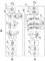
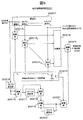
図1は本発明の第1実施形態が適用されたFH-M3FSK用モデム装置の概略図である。図示するように、本実施形態のFH-M3FSK用モデム装置は、送信データをFH-M3FSK信号に変換して送信する送信部10と、FH-M3FSK信号を受信して受信データに変換する受信部20と、を有する。
<< first embodiment >>
FIG. 1 is a schematic diagram of an FH-M 3 FSK modem device to which the first embodiment of the present invention is applied. As shown in the figure, the FH-M 3 FSK modem apparatus according to the present embodiment receives and receives a FH-M 3 FSK signal by transmitting a
送信部10は、S/P(Serial/Parallel)変換部101と、レベル変換部102と、パターン選択部103と、ホッピングパターン記憶部104と、加算部105と、剰余演算部106と、レベル-周波数演算部107と、IFFT(Inverse Fast Fourier Transform)部108と、同期信号付加部109と、DA(Digital Analog)変換部110と、AFE(Analog Front End)部111と、を有する。
The
送信部10に入力されたKビットのシリアルデータ(送信データ)は、S/P変換部101でパラレルデータに変換され、その上位(または下位)K1ビットがレベル変換部102に入力され、残りのK2ビットがパターン選択部103に入力される。
Serial data K bits inputted to the transmitting unit 10 (transmitting data) is converted into parallel data by the S /
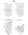
レベル変換部102は、S/P変換部101から入力されたK1ビットのパラレルデータを、当該パラレルデータが示す値に応じたレベルに変換する。そして、変換されたレベルが1ホッピングを構成するチップ(シンボル)数分(1チップの時間幅をτとする)連続して構成されたレベルパターンを加算部105に出力する。図2(a)は、レベル変換部102が出力するレベルパターン1021を模試的に表した図である。この例では、1ホッピングのチップ数=5、K1ビットのビット数=3、そして、K1ビットのパラレルデータが「011」の場合を示している。ビット数=3の場合、ビットデータがとり得る値は8通りとなる。このため、レベル数=8となる。
The
パターン選択部103は、S/P変換部101から入力されたK2ビットのパラレルデータが示す値に対応付けられたホッピングパターンをホッピングパターン記憶部104から読み出して加算部105に出力する。ここで、ホッピングパターン記憶部104には、K2ビットのパラデータがとり得る値毎にホッピングパターンが記憶されている。なお、ホッピングパターンのチップ数、レベル数は、レベル変換部102が出力するレベルパターンのチップ数、レベル数と同じである。図2(b)は、ホッピングパターン記憶部104に記憶されているホッピングパターン1041を模試的に表した図である。K2ビットのパラデータがとり得る値各々に対応付けるホッピングパターンは、チップ数×レベル数のマトリックスがとり得るパターンのうち、ホッピングパターンとして使える組合せ(他のホッピングパターンと識別可能な程度にバラツキがある組合せ)の中から選択される。
The
加算部105は、レベル変換部102から入力されたレベルパターンのレベルとパターン選択部103から出力されたホッピングパターンのレベルとをチップ毎に加算する。そして、加算結果を剰余演算部106に出力する。剰余演算部106は、加算部105から入力される各チップの加算結果に対して、レベルパターンおよびホッピングパターンのレベル数の剰余を演算する。つまり、加算結果をx、レベルパターンおよびホッピングパターンのレベル数をnとした場合、x(mod n)を計算する。そして、その計算結果をレベル-周波数変換部107に出力する。但し、計算結果が0の場合、レベル数nを計算結果として出力する。
Adder 105 adds the level of the level pattern input from
レベル-周波数変換部107は、予め登録されたレベル-周波数変換テーブルを用いて、剰余演算部106から入力される各チップの計算結果を、周波数の組合せ(周波数スペクトル)に変換し、IFFT部108に出力する。図2(c)は、レベル-周波数変換部107に登録されているレベル-周波数変換テーブル1071を模式的に表した図である。図示するように、剰余演算部106の計算結果がとり得る値毎、つまり、レベルパターンおよびホッピングパターンのレベル毎に、予め定められたn個の周波数のうちのm個の周波数の組合せが対応付けられている。この例では、レベルパターンおよびホッピングパターンのチップ数と同じ5個の周波数のうち、2個の周波数の組合せが対応付けられている。なお、利用される周波数は、チップの周波数(1/τ)の整数倍である。図2(d)は、レベル-周波数変換部107から出力される1ホッピング分(レベルパターンおよびホッピングパターンのチップ数分)の送信スペクトル1072を模式的に表した図である。この例では、加算部105に入力されたレベルパターン、ホッピングパターンが図2(a)、図2(b)に示すパターンであり、レベル-周波数変換部107に登録されたレベル-周波数変換テーブルが図2(c)に示すテーブルである場合に、レベル-周波数変換部107から出力される送信スペクトルを示している。
The level-
次に、IFFT部108は、レベル-周波数変換部107から入力される1ホッピング分の各チップの周波数スペクトルにIFFT処理を施して波形データに変換し、同期信号付加部109に出力する。
Next, IFFT
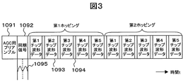
さて、同期信号付加部109は、IFFT部108から入力される各チップの波形データにサイクリックプリフィックス(cyclicprefix)を付加する。サイクリックプリフィックスは、FH-M3FSK信号の同期ずれによるシンボル(チップ)間干渉を回避するためのものである。チップ毎に、波形データの後部データをコピーして、これをサイクリックプリフィックスとして、当該波形データの前方へ付加する。また、同期信号付加部109は、少なくとも1ホッピング分の波形データで構成される通信フレームの先頭に、AGC(Auto Gain Control)用のプリアンブルと同期信号とを付加する。図3は同期信号付加部109から出力されるFH-M3FSK信号の通信フレームを模式的に表した図である。図示するように、本実施形態で用いるFH-M3FSK信号の通信フレームは、AGC用プリアンブル1091と、同期信号1092と、少なくとも1ホッピング分(ここでは2ホッピング分)のチップの波形データ1093と、各波形データ1093の前方に付加されたサイクリックプリフィックス1094と、を備えて構成される。なお、本実施形態では、同期信号1092として、図示するように、時間軸方向に左右対称の波形1095を有する信号(但し、変調信号(周波数ホッピング)に使用されていない周波数とする)を用いている。以上のようにして、同期信号付加部109は、AGC用プリアンブル、同期信号およびサイクリックプリフィックスが付加されたFH-M3FSK信号の通信フレームをDA変換部110に出力する。
The synchronization signal adding unit 109 adds a cyclic prefix to the waveform data of each chip input from the IFFT
次に、DA変換部110は、同期信号付加部109より出力されたFH-M3FSK信号の通信フレームをアナログ信号に変換する。このアナログ信号は、AFE部111を介してアンテナから送信される。
Next, the
一方、受信部20は、AFE部201と、AD(Analog Digital)変換部202と、同期部203と、FFT(Fast Fourier Transform)部204と、周波数-レベル変換部205と、ホッピングパターン記憶部206と、複数の減算部2071〜207nと、複数の剰余演算部2081〜208nと、多数決判定部209と、P/S(Parallel/Serial)変換部210と、を有する。
On the other hand, the receiving
AFE部201を介してアンテナから受信されたFH-M3FSK信号は、AD変換部202でデジタル信号に変換されて、同期信号検出部203に入力される。同期部203は、入力されたたFH-M3FSK信号から同期信号を検出し、検出した同期信号に基づいてFH-M3FSK信号の通信フレームを認識する。そして、認識した通信フレームに格納されているホッピング毎に、各チップの波形データをFFT部204に出力する。なお、同期部203の詳細については後述する。
The FH-M 3 FSK signal received from the antenna via the
次に、FFT部204は、同期部203から入力される1ホッピング分の各チップの波形データにFFT処理を施して周波数スペクトルに変換し、周波数-レベル変換部205に出力する。
Next, the
周波数-レベル変換部205には、通信相手のレベル-周波数変換部107に登録されているレベル-周波数変換テーブルと同じテーブルが登録されている。そして、このテーブルを用いて、FFT部204から入力される各チップの周波数スペクトル(周波数の組合せ)をレベルに変換し、減算部2071〜207nに出力する。
In the frequency-
ホッピングパターン記憶部206には、K2ビットのパラレルデータがとり得る値毎に、当該値に対応付けられて通信相手のホッピングパターン記憶部206に記憶されているホッピングパターンと同じパターンが記憶されている。減算部2071〜207nおよび剰余演算部2081〜208nは、ホッピングパターン記憶部206に記憶されているホッピングパターン毎に設けられている。減算部2071〜207nは、対応するホッピングパターンのレベルと周波数-レベル変換部205から出力される1ホッピング分のチップのレベルとをチップ毎に減算し、その減算結果を対応する剰余演算部2081〜208nに出力する。剰余演算部2081〜208nは、対応する減算部2071〜207nから入力された減算結果に対して、通信相手が使用するレベルパターンおよびホッピングパターンのレベル数の剰余を演算する。つまり、減算結果をy、通信相手が使用するレベルパターンおよびホッピングパターンのレベル数をnとした場合、y(mod n)を計算する。そして、その計算結果を多数決判定部209に出力する。
The hopping
多数決判定部209には、剰余演算部2081〜208n各々に対応付けられて、当該剰余演算部2081〜208nが対応付けられているホッピングパターンに対応するK2ビットのパラレルデータのデータ値が登録されている。さて、多数決判定部209は、剰余演算部2081〜208n各々から入力された1ホッピング分のチップの計算結果に対して多数決判定を行い、同じ計算結果を持つチップを最も多く含む1ホッピング分のチップの計算結果を出力した剰余演算部2081〜208nを特定する。そして、特定した剰余演算部2081〜208nが最も多く出力したチップの計算結果(レベル)に応じた値のK1ビットのパラレルデータを出力すると共に、特定した剰余演算部2081〜208nに対応付けられて登録されているK2ビットのパラレルデータを出力する。
The
P/S変換部210は、多数決判定部209から出力されたK1ビット、K2ビットのパラレルデータを、K1ビットを上位(あるいは下位)ビットデータとし、K2ビットを残りのビットデータとするKビットのシリアルデータ(受信データ)に変換し出力する。
P /
なお、上述したFH-M3FSK用モデム装置の各構成は、ASIC(Application Specific Integrated Circuit)、FPGA(Field Programmable Gate Array)などの集積ロジックICによりハード的に実行されるものでもよいし、あるいは、DSP(Digital Signal Processor)など計算機によりソフトウエア的に実行されるものでもよい。 Each configuration of the above-described FH-M 3 FSK modem device may be executed in hardware by an integrated logic IC such as an application specific integrated circuit (ASIC) or a field programmable gate array (FPGA). , A DSP (Digital Signal Processor) or the like executed by a computer by a computer.
次に、同期部203の詳細について説明する。
Next, details of the
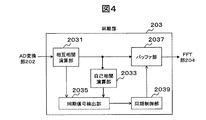
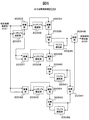
図4は同期部203の概略構成図である。図示するように、同期部203は、相互相関演算部2031と、自己相関演算部2033と、同期信号検出部2035と、バッファ部2037と、同期制御部2039と、を有する。
FIG. 4 is a schematic configuration diagram of the
相互相関演算部2031は、AD変換部202から入力されたFH-M3FSK信号のデジタル信号に対して、予め記憶された同期信号の波形データとの相関を検出する相互相関演算を行う。具体的には、同期信号の波形データのA/D変換によるサンプルデータをY1〜Ymとし(サンプル数m)、AD変換部202から逐次出力されるFH-M3FSK信号のサンプルデータをXiとした場合、((ΣXi・Yi)/m)/(√(ΣXi 2・ΣYi 2)/m2)、あるいは、簡易的に、(ΣXi・Yi)/(ΣXi 2・ΣYi 2)を計算する。但し、Σはi=1〜mの総和である。
The
図5は相互相関演算部2031の概略構成例を示す図である。図示するように、相互相関演算部2031は、遅延部20311と、同期信号波形データ記憶部20312と、複数の乗算部203131〜20313mと、加算部20314と、1サンプル遅延部20315と、乗算部20316と、mサンプル遅延部20317と、減算部20318と、加算部20319と、1サンプル遅延部20320と、乗算部20321と、割算部20322と、を有する。各遅延部には、例えばシフトレジスタが用いられる。
FIG. 5 is a diagram illustrating a schematic configuration example of the
遅延部20311は、1サンプル遅延処理回路〜mサンプル遅延処理回路を有する。そして、サンプルクロックに従ってAD変換部202から逐次出力されるFH-M3FSK信号のサンプルデータに対し、1サンプル遅延処理〜mサンプル遅延処理を行い、各遅延処理回路から遅延サンプルデータを出力する。このうちm遅延処理回路から出力された遅延サンプルデータは、自己相関演算部2033およびバッファ部2037に出力される。
The
同期信号波形データ記憶部20312は、同期信号の波形データを構成するm個のサンプルデータY1〜Ymと、これらのサンプルデータ各々の自乗の総和ΣYi 2と、が記憶されている(但し、Σはi=1〜mの総和)。
Synchronizing signal waveform
乗算部203131〜20313mは、同期信号波形データ記憶部20312に記憶されている同期信号の波形データを構成するm個のサンプルデータY1〜Ymのそれぞれに対応付けられて設けられている。乗算部20313i(但しi=1〜m)は、同期信号波形データ記憶部20312に記憶されている同期信号の波形データを構成するi番目のサンプルデータYiと遅延部20311のiサンプル遅延処理回路から出力されたサンプルデータXiとの乗算を行い、その乗算結果Xi・Yiを加算部20314に出力する。加算部20314は、乗算部203131〜20313mから入力された乗算結果X1・Y1〜Xm・Ymの総和ΣXi・Yiを計算し、計算結果を割算部20322に出力する。
Multiplying
1サンプル遅延部20315は、サンプルクロックに従ってAD変換部202から逐次出力されるFH-M3FSK信号のサンプルデータに対し1サンプル遅延処理を行う。乗算部20316は、1サンプル遅延部20315から出力された1サンプル遅延処理されたサンプルデータX1の自乗を行う。mサンプル遅延部20317は、乗算部20317から出力された計算結果X1 2に対しmサンプル遅延処理を行う。減算部20318は、乗算部20317から出力された計算結果X1 2と、mサンプル遅延部20317によりmサンプル遅延処理された加算部20317の計算結果Xm+1 2との減算を行う。加算部20319は、減算部20318から出力された計算結果X1 2-Xm+1 2と、1サンプル遅延部20320により1サンプル遅延処理された加算部20319の計算結果ΣXi+1 2との加算を行う(但し、Σはi=1〜mの総和)。この結果、加算部20319からの出力は、ΣXi 2となる(但し、Σはi=1〜mの総和)。
The 1-
次に、乗算部20321は、加算部20319の計算結果ΣXi 2と、同期信号波形データ記憶部20312に記憶されている同期信号の波形データを構成するm個のサンプルデータの自乗の総和ΣYi 2とを乗算する(但し、Σはi=1〜mの総和)。そして、割算部20322は、加算部20314の計算結果ΣXi・Yiと、乗算部20321の計算結果ΣXi 2・ΣYi 2との割算を行い、その結果(ΣXi・Yi)/(ΣXi 2・ΣYi 2)を、相互相関値として同期検出部2035に出力する(但し、Σはi=1〜mの総和)。
Then, multiplying
自己相関演算部2033は、AD変換部202から逐次出力されるFH-M3FSK信号のサンプルデータのmサンプル分(ここで、mは同期信号の波形データのサンプル数である)に対して、前方m/2サンプル分のサンプルデータと後方m/2サンプル分のサンプルデータとの相関、つまり、時間軸方向の左右対称性を検出する自己相関演算を行う。具体的には、((ΣXL-i・XL-i-m/2)/m)/(√(ΣXL-i 2・ΣXL-i-m/2 2)/m2)、あるいは、簡易的に、(ΣXL-i・XL-i-m/2)/(ΣXL-i 2・ΣXL-i-m/2 2)を計算する。但し、Σはi=1〜m/2の総和である。
The
図6は自己相関演算部2033の概略構成例を示す図である。図示するように、自己相関演算部2033は、m/2サンプル遅延部20331と、乗算部20332と、m/2サンプル遅延部20333と、減算部20334と、加算部20335と、1サンプル遅延部20336と、乗算部20337と、m/2サンプル遅延部20338と、減算部20339と、加算部20340と、1サンプル遅延部20341と、乗算部20342と、m/2サンプル遅延部20343と、減算部20344と、加算部20345と、1サンプル遅延部20346と、乗算部20347と、割算部20348と、を有する。各遅延部には、例えばシフトレジスタが用いられる。
FIG. 6 is a diagram illustrating a schematic configuration example of the
m/2サンプル遅延部20331は、相互相関演算部2031から出力されるFH-M3FSK信号のサンプルデータXLに対しm/2サンプル遅延処理を行う。乗算部20332は、相互相関演算部2031から出力されたFH-M3FSK信号のサンプルデータXLと、m/2サンプル遅延部20331から出力されたm/2サンプル遅延処理されたサンプルデータXL-m/2との乗算を行う。m/2サンプル遅延部20333は、乗算部20332から出力された計算結果XL・XL-m/2に対しm/2サンプル遅延処理を行う。減算部20334は、乗算部20332から出力された計算結果XL・XL-m/2と、m/2サンプル遅延部20333によりm/2サンプル遅延処理された乗算部20332の計算結果XL-m/2・XL-mとの減算を行う。加算部20335は、減算部20334から出力された計算結果XL・XL-m/2-XL-m/2・XL-mと、1サンプル遅延部20336により1サンプル遅延処理された加算部20335の計算結果ΣXL-i-1・XL-i-m/2-1との加算を行う(但し、Σはi=1〜m/2の総和)。この結果、加算部20335からの出力は、ΣXL-i・XL-i-m/2となる(但し、Σはi=1〜m/2の総和)。
m / 2
また、乗算部20337は、m/2サンプル遅延部20331から出力されたサンプルデータXL-m/2の自乗を行う。m/2サンプル遅延部20338は、乗算部20337から出力された計算結果XL-m/2 2に対しm/2サンプル遅延処理を行う。減算部20339は、乗算部20337から出力された計算結果XL-m/2 2と、m/2サンプル遅延部20338によりm/2サンプル遅延処理された乗算部20338の計算結果XL-m 2との減算を行う。加算部20340は、減算部20339から出力された計算結果XL-m/2 2-XL-m 2と、1サンプル遅延部20341により1サンプル遅延処理された加算部20340の計算結果ΣXL-i-m/2-1 2との加算を行う(但し、Σはi=1〜m/2の総和)。この結果、加算部20340からの出力は、ΣXL-i-m/2 2となる(但し、Σはi=1〜m/2の総和)。
Further, the
また、乗算部20342は、相互相関演算部2031から逐次出力されるFH-M3FSK信号のサンプルデータXLの自乗を行う。m/2サンプル遅延部20343は、乗算部20342から出力された計算結果XL 2に対しm/2サンプル遅延処理を行う。減算部20344は、乗算部20342から出力された計算結果XL 2と、m/2サンプル遅延部20343によりm/2サンプル遅延処理された乗算部20342の計算結果XL-m/2 2との減算を行う。加算部20345は、減算部20344から出力された計算結果XL 2-XL-m/2 2と、1サンプル遅延部20346により1サンプル遅延処理された加算部20345の計算結果ΣXL-i-1 2との加算を行う(但し、Σはi=1〜m/2の総和)。この結果、加算部20345からの出力は、ΣXL-i 2となる(但し、Σはi=1〜m/2の総和)。
Further, multiplying
乗算部20347は、加算部20340の計算結果ΣXL-i-m/2 2と、加算部20345の計算結果ΣXL-i 2とを乗算する(但し、Σはi=1〜m/2の総和)。割算部20348は、加算部20335の計算結果ΣXL-i・XL-i-m/2と、乗算部20347の計算結果ΣXL-i 2・ΣXL-i-m/2 2との割算を行い、その結果(ΣXL-i・XL-i-m/2)/(ΣXL-i 2・ΣXL-i-m/2 2)を、自己相関値として同期検出部2035に出力する(但し、Σはi=1〜m/2の総和)。
Multiplying
バッファ部2037は、AD変換部202から逐次出力されるFH-M3FSK信号のサンプルデータを、相互相関演算部2031を介して受信しバッファリングする。同期信号検出部2035は、相互相関演算部2031から出力される相互相関値および自己相関演算部2033から出力される自己相関値に基づいて、AD変換部202から逐次出力されるFH-M3FSK信号から同期信号を検出する。そして、同期制御部2039は、同期信号検出部2035により検出された同期信号に基づいてFH-M3FSK信号の通信フレームを認識し、バッファ部2037に格納されたサンプルデータの読み出しを制御することで、FH-M3FSK信号の同期を図る。
The
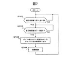
図7は同期信号検出部2035の動作フローを説明するための図である。このフローは、相互相関演算部2031および自己相関演算部2033が、それぞれ図5、図6に示す構成を有することを前提にしている。
FIG. 7 is a diagram for explaining the operation flow of the synchronization
同期信号検出部2035は、相互相関演算部2031から逐次送られてくる相互相関値を予め定められたしきい値と比較する(S101)。そして、相互相関値がしきい値以上となったならば、自己相関演算部2033から逐次送られてくる自己相関値の監視を開始し、自己相関値のピーク値を検出する(S102)。上述したように、本実施形態では同期信号として時間軸方向に左右対称の波形データを用いている。相互相関値がしきい値以上となった時点から決められた時間内の自己相関値のピーク値を検出する。例えば、相互相関値がしきい値以上となってから少なくとも1シンボル(チップ)以内に同期ポイントがあることから、1シンボル以内で自己相関値のピーク値をサーチする。
The synchronization
さて、同期信号検出部2035は、自己相関値のピーク値を検出したならば、その検出タイミングに基づいて、バッファ部2037に記憶されているサンプルデータの中から、同期信号を構成するmサンプル分のサンプルデータを特定する(S103)。具体的には、自己相関演算部2033から前回送られてきた値をピーク値として検出した場合、バッファ部2037に登録されている最新のサンプルデータの1つ前のサンプルデータからm+1つ前のサンプルデータまでのm個のサンプルデータを、同期信号に特定する。そして、同期信号検出部2035は、同期制御部2039を制御し、特定した同期信号に基づいてFH-M3FSK信号の通信フレームの同期を図り、バッファ部2037からデータを読み出す(S104)。
When the synchronization
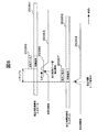
図8は同期信号検出部205の同期信号検出タイミングを説明するための図である。このタイミングは、相互相関演算部2031および自己相関演算部2033が、それぞれ図5、図6に示す構成を有することを前提にしている。
FIG. 8 is a diagram for explaining the synchronization signal detection timing of the synchronization
図8において、符号20361は相互相関演算部2031に入力されるFH-M3FSK信号を、そして、符号20361は自己相関演算部2033に入力されるFH-M3FSK信号を示している。自己相関演算部2033には、相互相関演算部2031の遅延部20311のmサンプル遅延処理回路を介してFH-M3FSK信号が入力されるため、図示するように、自己相関演算部2033に入力されるFH-M3FSK信号は、相互相関演算部2031に入力されるFH-M3FSK信号に対してmサンプル分の遅延がある。さて、相互相関演算部2031から出力される相互相関値20363は、同期信号波形データ記憶部20312に記憶されている同期信号の波形データ20365に近似してくるほど高くなる。そして、相互相関値20363が所定のしきい値20366以上になると、同期信号検出部205は、自己相関演算部2033から出力される自己相関値20364のピーク値検出を開始する。自己相関演算部2033から出力される自己相関値20364は、連続するmサンプル分のサンプルデータ20367の左右対称性が高くなる程高くなる。同期信号検出部205は、自己相関値20364のピーク値を検出すると、そのピーク値検出の対象なった連続するmサンプル分のサンプルデータ20367を同期信号に特定する。
In FIG. 8,
以上、本発明の第1実施形態について説明した。本実施形態によれば、FH-M3FSK信号の通信フレームに付加された同期信号を用いて通信フレームを認識するので、情報が割当てられた複数のホッピングパターンのそれぞれについて相関演算を行う必要がない。このため、受信部20の回路規模を小さくすることができる。
The first embodiment of the present invention has been described above. According to the present embodiment, since the communication frame is recognized using the synchronization signal added to the communication frame of the FH-M 3 FSK signal, it is necessary to perform a correlation operation for each of a plurality of hopping patterns to which information is assigned. Absent. For this reason, the circuit scale of the
また、本実施形態では、同期信号の検出に相互相関演算および自己相関演算の両方を用いている。受信側に同期信号と同じ波形データを保持させて、受信信号との相互相関演算を行う場合、伝送路上での波形歪みやノイズなどにより検出精度が損なわれる場合がある。そこで、本実施形態では、時間軸方向に左右対称の波形を有する同期信号を用い、受信側で受信信号の時間軸方向の左右対称性を検出する自己相関演算を、上記の相互相関演算と併用している。これにより、検出精度を向上させることができる。 In this embodiment, both the cross-correlation calculation and the autocorrelation calculation are used for detecting the synchronization signal. When the reception side holds the same waveform data as that of the synchronization signal and performs cross-correlation calculation with the reception signal, detection accuracy may be impaired due to waveform distortion or noise on the transmission path. Therefore, in the present embodiment, the autocorrelation calculation for detecting the left-right symmetry in the time axis direction of the received signal is used in combination with the above-described cross correlation calculation, using a synchronization signal having a waveform symmetrical in the time axis direction. is doing. Thereby, detection accuracy can be improved.
<<第2実施形態>>
次に、本発明の第2実施形態について説明する。本実施形態のFH-M3FSK用モデム装置が図1に示す第1実施形態のものと異なる点は、送信部10の同期信号付加部109に代えて同期信号付加部109aを設けたこと、および、受信部20の同期部203に代えて同期部203aを設けたことにある。その他の構成は第1実施形態のものと同じである。
<< Second Embodiment >>
Next, a second embodiment of the present invention will be described. The FH-M 3 FSK modem device of this embodiment is different from that of the first embodiment shown in FIG. 1 in that a synchronization signal adding unit 109a is provided instead of the synchronization signal adding unit 109 of the
第1実施形態の同期信号付加部109は、付加する同期信号として時間軸方向に左右対称の波形を有する信号を用いている。これに対して、本実施形態の同期信号付加部109aは、付加する同期信号として、変調信号に使用されていない周波数又は変調信号に使用される周波数であっても組合せが異なる同期信号波形であって、時間軸方向に4以上の偶数に区分に分割した場合に、相似の波形を有する組合せを有する信号を用いている。 The synchronization signal adding unit 109 of the first embodiment uses a signal having a symmetrical waveform in the time axis direction as the added synchronization signal. On the other hand, the synchronization signal adding unit 109a of the present embodiment has a synchronization signal waveform having a different combination even if it is a frequency that is not used for a modulation signal or a frequency that is used for a modulation signal as a synchronization signal to be added. Thus, a signal having a combination having a similar waveform is used when divided into four or more even numbers in the time axis direction.
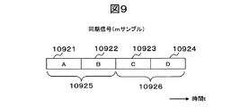
図9は本発明の第2実施形態で用いる同期信号の一例を模式的に表した図である。この例では、同期信号として、チップの周波数(1/τ)の4倍、8倍および16倍の周波数の組合せを用いることで、同期信号を4つの区分10921〜10924に分割した場合に、区分A10921と区分B10922との相関、区分C10923と区分D10924との相関、および、区分A、Bからなる区分10925と区分C、Dからなる区分10926との相関が、それぞれ高くなる(相似形となる)ようにしている。チップの周波数(1/τ)の4倍、8倍および16倍の周波数で構成された同期信号は、このような3つの相関がある。しかし、チップの周波数(1/τ)の4倍、8倍および16倍の周波数は、変調信号に用いられていないため、FH-M3FSK信号の各チップの波形データとの相関は低くなる。
FIG. 9 is a diagram schematically showing an example of the synchronization signal used in the second embodiment of the present invention. In this example, when the synchronization signal is divided into four
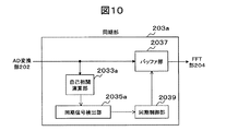
図10は同期部203aの概略構成図である。図示するように、同期部203aは、自己相関演算部2033aと、同期信号検出部2035aと、バッファ部2037と、同期制御部2039と、を有する。
FIG. 10 is a schematic configuration diagram of the
自己相関演算部2033aは、AD変換部202から逐次出力されるFH-M3FSK信号のサンプルデータのmサンプル分(ここで、mは同期信号の波形データのサンプル数である)を、時間軸方向に4以上の偶数の区分に分割し、複数の所定の区分の組合せ各々について自己相関演算を行う。
The
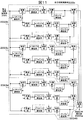
図11は自己相関演算部2033aの概略構成例を示す図である。この例では、同期信号が図9に示す3つの相関を有することを前提としている。図示するように、自己相関演算部2033aは、3つの相関演算部2033b〜2033dと、各相関演算部2033b〜2033dの計算結果を乗算して、その乗算結果を同期信号検出部2035aに出力する乗算部20349と、を有する。
FIG. 11 is a diagram illustrating a schematic configuration example of the
3つの相関演算部2033b〜2033d各々の構成は、基本的に図6に示す第1実施形態の自己相関演算部2033と同様である。但し、相関演算部2033bは、図9に示す区分A10921と区分B10922との自己相関値(ΣXL-i・XL-i-m/4)/(ΣXL-i 2・ΣXl-i-m/4 2)を演算する(但し、Σはi=1〜m/4の総和)。このために、遅延部20331、20333、20338、20343のそれぞれは、m/2サンプル遅延処理に代えてm/4サンプル遅延処理を行う。また、相関演算部2033cは、図9に示す区分C10923と区分D10924との自己相関値(ΣXL-i-m/2・XL-i-3m/4)/(ΣXL-i-m/2 2・ΣXL-i-3m/4 2)を演算する(但し、Σはi=1〜m/4の総和)。このために、遅延部20333、20338、20343のそれぞれは、m/2サンプル遅延処理に代えてm/4サンプル遅延処理を行う。なお、相関演算部2033dは、図9に示す区分A、Bからなる区分10925と区分C、Dからなる区分10926との自己相関値(ΣXL-i・XL-i-m/2)/(ΣXL-i 2・ΣXL-i-m/2 2)を演算する(但し、Σはi=1〜m/2の総和)。したがって、図6に示す第1実施形態の自己相関演算部2033と全く同様である。
The configuration of each of the three
バッファ部2037は、AD変換部202から逐次出力されるFH-M3FSK信号のサンプルデータを受信しバッファリングする。同期信号検出部2035aは、自己相関演算部2033aから出力される自己相関値に基づいて、AD変換部202から逐次出力されるFH-M3FSK信号から同期信号を検出する。同期信号検出部2035aの動作フローは、図7に示す第1実施形態の動作フローからステップS101を省略したものとなる。そして、同期制御部2039は、同期信号検出部2035により検出された同期信号に基づいてFH-M3FSK信号の通信フレームを認識し、バッファ部2037に格納されたサンプルデータの読み出しを制御することで、FH-M3FSK信号の同期を図る。
The
以上、本発明の第2実施形態について説明した。本実施形態では、同期信号として、変調信号(周波数ホッピング)に使用されていない周波数の組合せからなる信号であって、時間軸方向に4以上の偶数の区分に分割した場合に、相似の波形を有する組合せを複数有する信号を用い、受信側において、FH-M3FSK信号のサンプルデータのmサンプル分(ここでmは同期信号の波形データのサンプル数である)を、時間軸方向に4以上の偶数の区分に分割し、複数の所定の区分の組合せ各々について自己相関演算を行うことで、受信したFH-M3FSK信号から同期信号を検出することにより、相互相関演算処理を行うことなく同期信号を検出している。このため、第1実施形態に比べ、受信部20の回路規模をさらに小さくすることができる。
The second embodiment of the present invention has been described above. In this embodiment, as a synchronization signal, a signal composed of a combination of frequencies that are not used for a modulation signal (frequency hopping), and a similar waveform is obtained when divided into four or more even segments in the time axis direction. Using a signal having a plurality of combinations, at the receiving side, m samples of sample data of the FH-M 3 FSK signal (where m is the number of samples of waveform data of the synchronization signal) are 4 or more in the time axis direction. Without performing cross-correlation calculation processing by detecting the synchronization signal from the received FH-M 3 FSK signal. A sync signal is detected. Therefore, the circuit scale of the receiving
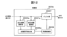
なお、本実施形態では、単一周波数の連続妨害波がチップの周波数(1/τ)の4倍、8倍、16倍であった場合に、同期信号を誤検出する可能性がある。そこで、自己相関値がピーク値となるFH-M3FSK信号のサンプルデータのmサンプル分に対して相互相関演算処理を行い、相互相関値が所定のしきい値以上である場合にのみ、このmサンプル分のサンプルデータを同期信号として検出するようにしてもよい。 In the present embodiment, there is a possibility that the synchronization signal is erroneously detected when the continuous interference wave having a single frequency is 4, 8, or 16 times the chip frequency (1 / τ). Therefore, the cross-correlation calculation process is performed on m samples of the sample data of the FH-M 3 FSK signal in which the autocorrelation value becomes the peak value, and only when the cross-correlation value is equal to or greater than a predetermined threshold value. Sample data for m samples may be detected as a synchronization signal.
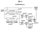
図12は本発明の第2実施形態で用いる同期部203aの変形例であり、相互相関演算部2031aが追加されている。相互相関演算部2031aは、AD変換部202から逐次出力されるFH-M3FSK信号のサンプルデータをm個分保持し、このm個のサンプルデータと予め記憶されている同期信号の波形データ(m個のサンプルデータ)との相関を計算する。
FIG. 12 shows a modification of the
図13は相互相関演算部2031aの概略構成図である。図示するように、相互相関演算部2031aは、シフトレジスタ20351と、シフトレジスタ20352と、同期信号波形データ記憶部20353と、シフトレジスタ20354と、乗算部20355と、加算部20356と、1サンプル遅延部20357と、乗算部20358と、加算部20359と、1サンプル遅延部20360と、割算部20361と、を有する。
FIG. 13 is a schematic configuration diagram of the
シフトレジスタ20351は、AD変換部202から逐次出力されるFH-M3FSK信号のサンプルデータを最新のものからmサンプル分(X1〜Xm)保持する。また、同期信号波形データ記憶部20353には、同期信号の波形データを構成するm個のサンプルデータY1〜Ymが記憶されている。
The
同期信号検出部2035aは、自己相関演算部2033aから出力された自己相関値のピーク値を検出すると、AD変換部202から逐次出力されるFH-M3FSK信号のサンプルデータのシフトレジスタ20351への入力を停止する。また、同期信号検出部2035aは、シフトレジスタ20352に、シフトレジスタ20351に保持されているmサンプル分のサンプルデータX1〜Xmをラッチさせ、順番に出力させると共に、シフトレジスタ20354に、同期信号波形データ記憶部20353に記憶されている同期信号の波形データを構成するmサンプル分のサンプルデータY1〜Ymをラッチさせ、順番に出力させる。
When the synchronization
乗算部20355は、シフトレジスタ20352から順番に出力されるサンプルデータXi(但しi=1〜m)と、シフトレジスタ20353から順番に出力されるサンプルデータYi(但しi=1〜m)とを乗算する。加算部20356は、乗算部20355の計算結果Xi・Yiと、1サンプル遅延部20357により1サンプル遅延処理された加算部20356の加算結果とを加算する。したがって、加算部20356の最終的な出力値はΣXi・Yiとなる(但しΣはi=1〜mの総和)。
The
一方、乗算部20358は、シフトレジスタ20352から順番に出力されるサンプルデータXi(但しi=1〜m)を自乗する。加算部20359は、乗算部20358の計算結果Xi 2と、1サンプル遅延部20360により1サンプル遅延処理された加算部20359の加算結果とを加算する。したがって、加算部20360の最終的な出力値はΣXi 2となる(但しΣはi=1〜mの総和)。
On the other hand, the
割算部20361は、加算部20356の出力値と加算部20360の出力値とを割算し、その結果を相互相関値として同期信号検出部2035aに出力する。したがって、割算部20361から出力される最終的な相互相関値は、(ΣXi・Yi)/ΣXi 2となる(但しΣはi=1〜mの総和)。
The
さて、同期信号検出部2035aは、相互相関演算部2031aから出力された最終的な相互相関値が予め定められたしきい値以上となったか否かを判断し、しきい値以上となった場合にのみ、シフトレジスタ20351に保持されているmサンプル分のサンプルデータ(自己相関値がピーク値となったmサンプル分のサンプルデータ)を同期信号として検出する。
When the synchronization
この変形例によれば、相互相関演算処理は、自己相関値がピーク値となったmサンプル分のサンプルデータに対してのみ行えばよい。このため、図13に示すように、相互相関演算部2031aの回路規模を、第1実施形態の相互相関演算部2031に比べて小さくすることができる。
According to this modification, the cross-correlation calculation process may be performed only on the sample data for m samples for which the autocorrelation value has reached the peak value. For this reason, as shown in FIG. 13, the circuit scale of the
なお、本発明は上記の実施形態に限定されるものではなく、その要旨の範囲内で数々の変形が可能である。例えば、上記の各実施形態ではFH-M3FSK用モデム装置に適用した場合を例にとり説明したが、本発明の同期技術はFH-MMFSK信号の同期を図る場合にも適用することができる。 In addition, this invention is not limited to said embodiment, Many deformation | transformation are possible within the range of the summary. For example, in each of the above embodiments, the case where the present invention is applied to the FH-M 3 FSK modem apparatus has been described as an example. However, the synchronization technique of the present invention can also be applied to the case where the synchronization of the FH-MMFSK signal is achieved.
10…送信部、20…受信部、101…S/P変換部、102…レベル変換部、103…パターン選択部、104…ホッピングパターン記憶部、105…加算部、106…剰余演算部、107…レベル-周波数変換部、108…IFFT部、109…同期信号付加部、110…DA変換部、111…AFE部、201…AFE部、202…AD変換部、203…同期部、203a…同期部、204…FFT部、205…周波数-レベル変換部、206…ホッピングパターン記憶部、207…減算部、208…剰余演算部、209…多数決判定部、210…P/S変換部、2031…相互相関演算部、2031a…相互相関演算部、2033…自己相関演算部、2033a…自己相関演算部、2035…同期信号検出部、2035a…同期信号検出部、2037…バッファ部、2039…同期制御部
DESCRIPTION OF
Claims (6)
送信側装置が、通信フレームに、時間軸方向に左右対称の信号波形を有する同期信号を付加して送信する送信ステップを行い、
受信側装置が、前記送信側装置からの受信信号に対して、予め記憶された同期信号の波形データとの相関を計算する相互相関演算、および、時間軸方向の左右対称性を計算する自己相関演算を行って、前記受信信号から同期信号を検出し、検出した同期信号に基づいて通信フレームを認識する受信ステップを行なうこと
を特徴とする通信の同期方法。 FH-MMFSK a - - (M-ary Multilevel Multitone FSK Frequency Hopping) method of synchronizing communication using, (Frequency Hopping M-ary Multilevel FSK) or FH-M 3 FSK
The transmission side device performs a transmission step of transmitting a communication frame by adding a synchronization signal having a symmetrical signal waveform in the time axis direction,
The cross-correlation calculation for the reception side apparatus to calculate the correlation with the waveform data of the synchronization signal stored in advance for the received signal from the transmission side apparatus, and the autocorrelation for calculating the left-right symmetry in the time axis direction A communication synchronization method comprising: performing a reception step of performing an operation to detect a synchronization signal from the reception signal and recognizing a communication frame based on the detected synchronization signal.
前記受信ステップは、前記送信装置からの受信信号に対して前記相互相関演算を行い、前記受信信号から前記予め記憶された同期信号の波形データと所定のしきい値以上の相関を有する信号部分を抽出し、抽出した信号部分の中から前記自己相関演算の結果がピーク値となる信号部分を特定し、特定した信号部分を同期信号として、前記受信信号から通信フレームを認識すること
を特徴とする通信の同期方法。 The communication synchronization method according to claim 1, comprising:
The reception step performs the cross-correlation operation on the reception signal from the transmission device, and a signal portion having a correlation equal to or greater than a predetermined threshold with the waveform data of the synchronization signal stored in advance from the reception signal. Extracting and identifying a signal part having a peak value as a result of the autocorrelation calculation from the extracted signal part, and identifying a communication frame from the received signal using the identified signal part as a synchronization signal. Communication synchronization method.
送信側装置が、通信フレームに、変調信号に使用されない周波数又は変調信号に使用されている周波数であっても組合せが異なる同期信号波形であって、時間軸方向に4以上の偶数の区分に分割した場合に、相似の波形を有する区分の組合せを複数有する同期信号を付加して送信する送信ステップを行い、
受信側装置が、前記送信側装置からの受信信号に対して、時間軸方向の波形の相関を計算する自己相関演算を行って、前記受信信号から同期信号を検出し、検出した同期信号に基づいて通信フレームを認識する受信ステップを行なうこと
を特徴とする通信の同期方法。 FH-MMFSK a - - (M-ary Multilevel Multitone FSK Frequency Hopping) method of synchronizing communication using, (Frequency Hopping M-ary Multilevel FSK) or FH-M 3 FSK
The transmission side device divides the communication frame into synchronization signal waveforms with different combinations even if the frequency is not used for the modulation signal or the frequency used for the modulation signal, and is divided into even segments of 4 or more in the time axis direction. In this case, a transmission step is performed in which a synchronization signal having a plurality of combinations of sections having similar waveforms is added and transmitted,
The reception side device performs autocorrelation calculation for calculating the correlation of the waveform in the time axis direction with respect to the reception signal from the transmission side device, detects the synchronization signal from the reception signal, and based on the detected synchronization signal And performing a reception step of recognizing a communication frame.
前記受信ステップは、前記送信装置からの受信信号に対して前記自己相関演算を行って、結果がピーク値となる信号部分を抽出し、抽出した信号部分と予め記憶された同期信号の波形データとの相互相関演算を行い、当該信号部分に対する前記相互相関演算の結果が所定のしきい値以上の相関を有することを示している場合に、当該信号部分を同期信号として、前記受信信号から通信フレームを認識すること
を特徴とする通信の同期方法。 The communication synchronization method according to claim 3, comprising:
The reception step performs the autocorrelation calculation on the reception signal from the transmission device, extracts a signal portion whose result is a peak value, and extracts the extracted signal portion and waveform data of a synchronization signal stored in advance. When the cross-correlation calculation of the signal portion indicates that the cross-correlation calculation result has a correlation equal to or higher than a predetermined threshold value, the received signal is used as a synchronization signal from the received signal. A communication synchronization method characterized by recognizing.
通信フレームに、時間軸方向に左右対称の信号波形を有する同期信号を付加して送信する送信部と、
通信相手からの受信信号に対して、予め記憶された同期信号の波形データとの相関を計算する相互相関演算、および、時間軸方向の左右対称性を計算する自己相関演算を行って、前記受信信号から同期信号を検出し、検出した同期信号に基づいて通信フレームを認識する受信部と、を有すること
を特徴とするモデム装置。 A - (M-ary Multilevel Multitone FSK Frequency Hopping) modem device, - FH-MMFSK (Frequency Hopping M-ary Multilevel FSK) or FH-M 3 FSK
A transmission unit that adds a synchronization signal having a symmetrical signal waveform in the time axis direction to the communication frame and transmits the frame,
The received signal from the communication partner is subjected to a cross-correlation operation for calculating a correlation with a waveform signal of a synchronization signal stored in advance and an autocorrelation operation for calculating a left-right symmetry in the time axis direction. And a receiving unit that detects a synchronization signal from the signal and recognizes a communication frame based on the detected synchronization signal.
通信フレームに、変調信号に使用されない周波数又は変調信号に使用されている周波数であっても組合せが異なる同期信号波形であって、時間軸方向に4以上の偶数の区分に分割した場合に、相似の波形を有する区分の組合せを複数有する同期信号を付加して送信する送信部と、
通信相手からの受信信号に対して、時間軸方向の波形の相関を計算する自己相関演算を行って、前記受信信号から同期信号を検出し、検出した同期信号に基づいて通信フレームを認識する受信部と、を有すること
を特徴とするモデム装置。 A - (M-ary Multilevel Multitone FSK Frequency Hopping) modem device, - FH-MMFSK (Frequency Hopping M-ary Multilevel FSK) or FH-M 3 FSK
Similar in the case where the communication frame is a synchronization signal waveform having a different combination even if it is a frequency that is not used for the modulation signal or a frequency that is used for the modulation signal, and is divided into four or more even sections in the time axis direction. A transmission unit for adding and transmitting a synchronization signal having a plurality of combinations of sections having the waveform of:
Receives a received signal from a communication partner by performing an autocorrelation operation that calculates the correlation of the waveform in the time axis direction, detects a synchronization signal from the received signal, and recognizes a communication frame based on the detected synchronization signal A modem device.
Priority Applications (1)
| Application Number | Priority Date | Filing Date | Title |
|---|---|---|---|
| JP2004233072A JP2006054540A (en) | 2004-08-10 | 2004-08-10 | Synchronization method of communication |
Applications Claiming Priority (1)
| Application Number | Priority Date | Filing Date | Title |
|---|---|---|---|
| JP2004233072A JP2006054540A (en) | 2004-08-10 | 2004-08-10 | Synchronization method of communication |
Publications (1)
| Publication Number | Publication Date |
|---|---|
| JP2006054540A true JP2006054540A (en) | 2006-02-23 |
Family
ID=36031746
Family Applications (1)
| Application Number | Title | Priority Date | Filing Date |
|---|---|---|---|
| JP2004233072A Pending JP2006054540A (en) | 2004-08-10 | 2004-08-10 | Synchronization method of communication |
Country Status (1)
| Country | Link |
|---|---|
| JP (1) | JP2006054540A (en) |
Cited By (8)
| Publication number | Priority date | Publication date | Assignee | Title |
|---|---|---|---|---|
| JP2007019985A (en) * | 2005-07-08 | 2007-01-25 | Mitsubishi Electric Corp | Receiver |
| JP2007228468A (en) * | 2006-02-27 | 2007-09-06 | Oki Electric Ind Co Ltd | Multi-carrier frequency hopping system, transmission circuit and receiving circuit |
| JP2008187487A (en) * | 2007-01-30 | 2008-08-14 | Kyocera Corp | Communicating system, base station, terminal, and communication method |
| WO2008146347A1 (en) * | 2007-05-25 | 2008-12-04 | Panasonic Corporation | Multicarrier transmitter and multicarrier receiver |
| JP2009518925A (en) * | 2005-12-08 | 2009-05-07 | コーニンクレッカ フィリップス エレクトロニクス エヌ ヴィ | System, apparatus and method for robust synchronization scheme for digital communication system |
| JP2009524299A (en) * | 2006-01-18 | 2009-06-25 | ホアウェイ・テクノロジーズ・カンパニー・リミテッド | Method for improving synchronization and information transmission in a communication system |
| JP2010520694A (en) * | 2007-03-05 | 2010-06-10 | ウエイブサット インク | Channel profiler and input signal profiling method |
| US8343313B2 (en) | 2006-03-01 | 2013-01-01 | Panasonic Corporation | Plant for production of paper-made part for speaker, paper-made part for speaker produced thereby, and speaker utilizing the same |
-
2004
- 2004-08-10 JP JP2004233072A patent/JP2006054540A/en active Pending
Cited By (17)
| Publication number | Priority date | Publication date | Assignee | Title |
|---|---|---|---|---|
| JP2007019985A (en) * | 2005-07-08 | 2007-01-25 | Mitsubishi Electric Corp | Receiver |
| JP4659540B2 (en) * | 2005-07-08 | 2011-03-30 | 三菱電機株式会社 | Receiver |
| JP2009518925A (en) * | 2005-12-08 | 2009-05-07 | コーニンクレッカ フィリップス エレクトロニクス エヌ ヴィ | System, apparatus and method for robust synchronization scheme for digital communication system |
| US8867636B2 (en) | 2006-01-18 | 2014-10-21 | Huawei Technologies Co., Ltd. | Method for improving synchronization and information transmission in a communication system |
| US10491369B2 (en) | 2006-01-18 | 2019-11-26 | Huawei Technologies Co., Ltd. | Method for improving synchronization and information transmission in a communication system |
| JP2009524299A (en) * | 2006-01-18 | 2009-06-25 | ホアウェイ・テクノロジーズ・カンパニー・リミテッド | Method for improving synchronization and information transmission in a communication system |
| US9369271B2 (en) | 2006-01-18 | 2016-06-14 | Huawei Technologies Co., Ltd. | Method for improving synchronization and information transmission in a communication system |
| US9337998B2 (en) | 2006-01-18 | 2016-05-10 | Huawei Technologies Co., Ltd. | Method for improving synchronization and information transmission in a communication system |
| US8139663B2 (en) | 2006-01-18 | 2012-03-20 | Huawei Technologies Co., Ltd. | Method for improving synchronization and information transmission in a communication system |
| JP2007228468A (en) * | 2006-02-27 | 2007-09-06 | Oki Electric Ind Co Ltd | Multi-carrier frequency hopping system, transmission circuit and receiving circuit |
| US8343313B2 (en) | 2006-03-01 | 2013-01-01 | Panasonic Corporation | Plant for production of paper-made part for speaker, paper-made part for speaker produced thereby, and speaker utilizing the same |
| JP2008187487A (en) * | 2007-01-30 | 2008-08-14 | Kyocera Corp | Communicating system, base station, terminal, and communication method |
| JP2010520694A (en) * | 2007-03-05 | 2010-06-10 | ウエイブサット インク | Channel profiler and input signal profiling method |
| JP5009982B2 (en) * | 2007-05-25 | 2012-08-29 | パナソニック株式会社 | Multi-carrier transmitter |
| WO2008146347A1 (en) * | 2007-05-25 | 2008-12-04 | Panasonic Corporation | Multicarrier transmitter and multicarrier receiver |
| US8249178B2 (en) | 2007-05-25 | 2012-08-21 | Panasonic Corporation | Multicarrier transmitter and multicarrier receiver |
| JPWO2008146347A1 (en) * | 2007-05-25 | 2010-08-12 | パナソニック株式会社 | Multi-carrier transmitter and multi-carrier receiver |
Similar Documents
| Publication | Publication Date | Title |
|---|---|---|
| US8090004B2 (en) | Spectrum spread communication method and system using very weak power, and high frequency radio apparatus | |
| KR100505678B1 (en) | Orthogonal Frequency Division Multiplexor transceiving unit of wireless Local Area Network system providing for symbol timing synchronization by double correlation and double peak comparison and symbol timing synchronization method thereof | |
| JP2007295544A (en) | Signal generating method, preamble signal, transmitter, receiver and synchronization method | |
| US7158541B2 (en) | Signal synchronization method and receiver device for packet communication | |
| JP4199269B2 (en) | Transmission device, reception device, transmission method, and reception method | |
| JP2006054540A (en) | Synchronization method of communication | |
| KR100900669B1 (en) | Wireless Personal Area Networks ZIGBEE RECEIVER AND RECEIVING METHOD THEREOF | |
| JP6061773B2 (en) | Signal processing apparatus, signal processing method, and signal processing program | |
| KR20010102190A (en) | Multibit spread spectrum signalling | |
| JP2006054542A (en) | Communication method and communication apparatus | |
| JP2009118175A (en) | Reception device | |
| JP2001223674A (en) | Spread spectrum demodulator | |
| JP3973332B2 (en) | Digital modulation / demodulation synchronization system | |
| JP5207956B2 (en) | Synchronization detection circuit, synchronization detection method, and receiving apparatus | |
| JP2001177496A (en) | Ofdm communication system and ofdm communication method | |
| JP2006054541A (en) | Communication method and communication apparatus | |
| JP3179554B2 (en) | Spread spectrum communication system | |
| US9143190B2 (en) | System and method for demodulating an incoming signal | |
| KR100323590B1 (en) | Apparatus and method for synchronizing using auto-correlation character | |
| JP2006074276A (en) | Method and apparatus for detecting timing | |
| JP4327842B2 (en) | COMMUNICATION SYSTEM, COMMUNICATION METHOD, AND PROGRAM | |
| JP4833024B2 (en) | COMMUNICATION SYSTEM, COMMUNICATION DEVICE, AND COMMUNICATION METHOD | |
| KR100693756B1 (en) | Apparatus and method of valid data detection in uwb system | |
| JP2006101129A (en) | Communication method and communication apparatus | |
| JP2008306367A (en) | Communication system and synchronization detecting apparatus |