EP1966570B1 - Method for checking the plausibility of a determined vehicle mass - Google Patents
Method for checking the plausibility of a determined vehicle mass Download PDFInfo
- Publication number
- EP1966570B1 EP1966570B1 EP06819497.6A EP06819497A EP1966570B1 EP 1966570 B1 EP1966570 B1 EP 1966570B1 EP 06819497 A EP06819497 A EP 06819497A EP 1966570 B1 EP1966570 B1 EP 1966570B1
- Authority
- EP
- European Patent Office
- Prior art keywords
- wheel
- load
- bend
- vehicle
- loads
- Prior art date
- Legal status (The legal status is an assumption and is not a legal conclusion. Google has not performed a legal analysis and makes no representation as to the accuracy of the status listed.)
- Active
Links
- 238000000034 method Methods 0.000 title claims description 17
- 230000005484 gravity Effects 0.000 description 15
- 230000003068 static effect Effects 0.000 description 4
- 230000001133 acceleration Effects 0.000 description 3
- 238000004364 calculation method Methods 0.000 description 2
- 230000007423 decrease Effects 0.000 description 2
- 238000011156 evaluation Methods 0.000 description 2
- 238000012544 monitoring process Methods 0.000 description 2
- 238000006243 chemical reaction Methods 0.000 description 1
- 230000002950 deficient Effects 0.000 description 1
- 230000001419 dependent effect Effects 0.000 description 1
- 238000010586 diagram Methods 0.000 description 1
- 238000006073 displacement reaction Methods 0.000 description 1
- 238000013178 mathematical model Methods 0.000 description 1
Images

Classifications
-
- G—PHYSICS
- G01—MEASURING; TESTING
- G01G—WEIGHING
- G01G19/00—Weighing apparatus or methods adapted for special purposes not provided for in the preceding groups
- G01G19/08—Weighing apparatus or methods adapted for special purposes not provided for in the preceding groups for incorporation in vehicles
- G01G19/086—Weighing apparatus or methods adapted for special purposes not provided for in the preceding groups for incorporation in vehicles wherein the vehicle mass is dynamically estimated
-
- B—PERFORMING OPERATIONS; TRANSPORTING
- B60—VEHICLES IN GENERAL
- B60G—VEHICLE SUSPENSION ARRANGEMENTS
- B60G17/00—Resilient suspensions having means for adjusting the spring or vibration-damper characteristics, for regulating the distance between a supporting surface and a sprung part of vehicle or for locking suspension during use to meet varying vehicular or surface conditions, e.g. due to speed or load
- B60G17/015—Resilient suspensions having means for adjusting the spring or vibration-damper characteristics, for regulating the distance between a supporting surface and a sprung part of vehicle or for locking suspension during use to meet varying vehicular or surface conditions, e.g. due to speed or load the regulating means comprising electric or electronic elements
- B60G17/016—Resilient suspensions having means for adjusting the spring or vibration-damper characteristics, for regulating the distance between a supporting surface and a sprung part of vehicle or for locking suspension during use to meet varying vehicular or surface conditions, e.g. due to speed or load the regulating means comprising electric or electronic elements characterised by their responsiveness, when the vehicle is travelling, to specific motion, a specific condition, or driver input
- B60G17/0162—Resilient suspensions having means for adjusting the spring or vibration-damper characteristics, for regulating the distance between a supporting surface and a sprung part of vehicle or for locking suspension during use to meet varying vehicular or surface conditions, e.g. due to speed or load the regulating means comprising electric or electronic elements characterised by their responsiveness, when the vehicle is travelling, to specific motion, a specific condition, or driver input mainly during a motion involving steering operation, e.g. cornering, overtaking
-
- G—PHYSICS
- G01—MEASURING; TESTING
- G01M—TESTING STATIC OR DYNAMIC BALANCE OF MACHINES OR STRUCTURES; TESTING OF STRUCTURES OR APPARATUS, NOT OTHERWISE PROVIDED FOR
- G01M1/00—Testing static or dynamic balance of machines or structures
- G01M1/12—Static balancing; Determining position of centre of gravity
- G01M1/122—Determining position of centre of gravity
-
- B—PERFORMING OPERATIONS; TRANSPORTING
- B60—VEHICLES IN GENERAL
- B60G—VEHICLE SUSPENSION ARRANGEMENTS
- B60G2400/00—Indexing codes relating to detected, measured or calculated conditions or factors
- B60G2400/60—Load
- B60G2400/61—Load distribution
-
- B—PERFORMING OPERATIONS; TRANSPORTING
- B60—VEHICLES IN GENERAL
- B60G—VEHICLE SUSPENSION ARRANGEMENTS
- B60G2800/00—Indexing codes relating to the type of movement or to the condition of the vehicle and to the end result to be achieved by the control action
- B60G2800/01—Attitude or posture control
- B60G2800/012—Rolling condition
-
- B—PERFORMING OPERATIONS; TRANSPORTING
- B60—VEHICLES IN GENERAL
- B60G—VEHICLE SUSPENSION ARRANGEMENTS
- B60G2800/00—Indexing codes relating to the type of movement or to the condition of the vehicle and to the end result to be achieved by the control action
- B60G2800/24—Steering, cornering
-
- B—PERFORMING OPERATIONS; TRANSPORTING
- B60—VEHICLES IN GENERAL
- B60G—VEHICLE SUSPENSION ARRANGEMENTS
- B60G2800/00—Indexing codes relating to the type of movement or to the condition of the vehicle and to the end result to be achieved by the control action
- B60G2800/90—System Controller type
- B60G2800/91—Suspension Control
- B60G2800/915—Suspension load distribution
Definitions
- the invention relates to a method for detecting the loading state of a motor vehicle.
- the driving behavior of a vehicle e.g. with respect to the longitudinal or lateral dynamics is significantly influenced by its mass and center of gravity.
- the ideal brake force distribution significantly depends on the respective axle loads.
- the total weight of the vehicle may double by the payload.
- the center of gravity position can shift in the longitudinal direction by several dozen centimeters in the direction of the rear axle. Due to the different total weight, the behavior of driving dynamics and Radschlupfreglern is influenced.
- a loaded vehicle needs much higher drive torque to achieve satisfactory acceleration.
- the loaded drive axle can settle much more drive torque, without running the risk that the driven wheel is driven in excessively high drive slip.
- the model alone can not easily identify the estimated mass as defective.
- the mass estimation can be parameterized such that it is activated only when certain longitudinal acceleration and / or force thresholds are exceeded. In this way, the accuracy of mass estimation be maintained despite mentioned disturbances. However, it then decreases the availability of the estimate as the events that may be estimated decrease with increasing accuracy requirements.
- the US 6, 015, 192A discloses a system for estimating a vehicle speed and / or the coefficient of friction of a road surface.
- This system for wheeled vehicles comprises sensors for detecting the wheel speed, the wheel load, as well as the longitudinal drive or braking force. Depending on these sensor signals, the vehicle longitudinal speed and / or the friction coefficient of the road surface are determined in an estimation and control device.
- the information about the load state is the determination of whether the vehicle is unloaded or loaded. Already by this information a rough plausibilization of a mass estimate is possible.
- An advantageous embodiment of the invention is characterized in that the determination of the first wheel loads and the second wheel loads is performed such that does not change the loading or load distribution of the vehicle between the two determinations.
- An advantageous embodiment of the invention is characterized in that the wheel loads from the tire longitudinal force and the coefficient of friction of the contact between the tire and the road are determined.
- the invention comprises a device containing means for carrying out the abovementioned mentioned methods.
- the essence of the invention is based on the fact that a payload of the vehicle is reflected in changing wheel loads. Conversely, it can be concluded from the static and dynamic wheel loads on the load.
- the wheel loads can be calculated from the slip reaction of the wheel to a known tire longitudinal force.
- wheel loads depends on some of the parameters listed below (for example, tire longitudinal stiffness). Since some of these parameters may change during vehicle operation and could lead to a corresponding error in the wheel load calculation, it is advisable to make the wheel load changes in relation to each other. Assuming that the parameters are largely unknown, but are the same size on all four wheels, these parameters cut out and no longer represent a source of error.
- a typical van has more or less half the distance between the front and rear axles.
- the cargo bed is typically located in the rear of the vehicle.
- the center of gravity of the total mass moves in the direction of the rear axle.
- the wheel loads on the rear axle increase more than those of the front axle.
- the instantaneous coefficient of friction ⁇ results from the so-called ⁇ -slip curve of the tire, which in Fig. 1 is shown.
- the wheel slip ⁇ is plotted in the abscissa direction and the friction coefficient ⁇ is plotted in the ordinate direction.
- the tire longitudinal force Fb can be determined in the case of drive from the drive torque, in the case of braking from the braking force.
- the tire longitudinal slip ⁇ results from the measured wheel speed and the vehicle speed.
- the tire longitudinal stiffness C is a tire-dependent characteristic.
- the result of the wheel load analysis results either analytically directly as a longitudinal displacement or by heuristic evaluation of the input signals ("lifting inside rear wheel in light cornering") and output a payload probability ("vehicle unloaded").
- a plausibility check could be made by setting a minimum lower bounded mass limit to a plausible value, e.g. according to a partially loaded vehicle.
- a mass estimate for the vehicle takes place. With this mass estimation, the vehicle mass m1 is determined.
- an analysis of the wheel loads takes place. With these wheel loads, further information about the mass is obtained in block 202 according to the invention. This may be, for example, information about whether the vehicle is loaded or unloaded.
- block 203 is based This mass information verifies that the vehicle mass determined in block 200 is plausible or not.
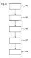
- Fig. 3 The course of the method according to the invention is in Fig. 3 shown.
- block 301 After the start of the method for detecting the loading state of a motor vehicle in block 300, in block 301, in the absence of cornering, first wheel loads of at least the inside rear wheel and the inside front wheel are determined. Subsequently, in block 302, when there is cornering, second wheel loads of at least the inside rear wheel and the inside front wheel are determined. Depending on the first and second wheel loads, information about the load state of the motor vehicle is determined in block 303. In block 304, the method ends.
Landscapes
- Engineering & Computer Science (AREA)
- Physics & Mathematics (AREA)
- General Physics & Mathematics (AREA)
- Aviation & Aerospace Engineering (AREA)
- Mechanical Engineering (AREA)
- Control Of Driving Devices And Active Controlling Of Vehicle (AREA)
- Regulating Braking Force (AREA)
- Electric Propulsion And Braking For Vehicles (AREA)
- Arrangement And Driving Of Transmission Devices (AREA)
Description
Die Erfindung betrifft ein Verfahren zur Detektion des Beladungszustandes eines Kraftfahrzeugs.The invention relates to a method for detecting the loading state of a motor vehicle.
Das Fahrverhalten eines Fahrzeugs z.B. bzgl. der Längs- oder Querdynamik wird wesentlich durch seine Masse und Schwerpunktslage beeinflusst. So hängt z.B. die ideale Bremskraftverteilung wesentlich von den jeweiligen Achslasten ab.The driving behavior of a vehicle e.g. with respect to the longitudinal or lateral dynamics is significantly influenced by its mass and center of gravity. For example, the ideal brake force distribution significantly depends on the respective axle loads.
Bei Fahrzeugen mit einer großen möglichen Zuladung kann sich das Gesamtgewicht des Fahrzeugs durch die Zuladung verdoppeln. Dabei kann sich die Schwerpunktslage in Längsrichtung um mehrere Dutzend Zentimeter in Richtung der Hinterachse verschieben. Durch das unterschiedliche Gesamtgewicht wird das Verhalten von Fahrdynamik- und Radschlupfreglern beeinflusst. So benötigt beispielsweise ein beladenes Fahrzeug ein viel höheres Antriebsmoment, um eine zufriedenstellende Beschleunigung zu erreichen. Gleichzeitig kann die beladene Antriebsachse viel mehr Antriebsmoment absetzen, ohne dabei Gefahr zu laufen, dass das angetriebene Rad in übermäßig hohen Antriebsschlupf getrieben wird.For vehicles with a large possible payload, the total weight of the vehicle may double by the payload. The center of gravity position can shift in the longitudinal direction by several dozen centimeters in the direction of the rear axle. Due to the different total weight, the behavior of driving dynamics and Radschlupfreglern is influenced. For example, a loaded vehicle needs much higher drive torque to achieve satisfactory acceleration. At the same time, the loaded drive axle can settle much more drive torque, without running the risk that the driven wheel is driven in excessively high drive slip.
Die derzeit bekannten Konzepte zur Schätzung der Masse weisen den Nachteil auf, dass sie relativ empfindlich auf Störungen bzw. Veränderungen der Eingangssignale und Systemparameter reagieren.The currently known concepts for estimating the mass have the disadvantage that they are relatively sensitive to disturbances or changes in the input signals and system parameters.
Da die mangelnde Genauigkeit schon im zugrunde gelegten Model verankert ist, kann allein durch das Modell die geschätzte Masse nicht ohne weiteres als fehlerhaft erkannt werden. Je nach Implementierung kann die Massenschätzung so parametrisiert werden, dass sie erst bei Überschreiten bestimmter Längsbeschleunigungs- und/oder Kraft-Schwellen aktiviert wird. Auf diese Weise kann die Genauigkeit der Massenschätzung trotz erwähnter Störgrößen beibehalten werden. Es nimmt dann jedoch die Verfügbarkeit der Schätzung ab, da die Ereignisse, bei denen geschätzt werden darf, mit zunehmender Anforderung an die Genauigkeit abnehmen.Since the lack of accuracy is already anchored in the underlying model, the model alone can not easily identify the estimated mass as defective. Depending on the implementation, the mass estimation can be parameterized such that it is activated only when certain longitudinal acceleration and / or force thresholds are exceeded. In this way, the accuracy of mass estimation be maintained despite mentioned disturbances. However, it then decreases the availability of the estimate as the events that may be estimated decrease with increasing accuracy requirements.
Aus der
Die
Aus
Aus der
Die Merkmale des Oberbegriffs von Anspruch 1 sind der
Die Erfindung betrifft ein Verfahren zur Detektion des Beladungszustandes eines Kraftfahrzeugs, bei dem
- bei Nichtvorliegen einer Kurvenfahrt erste Radlasten aller vier Räder oder zumindest wenigstens des späteren kurveninneren Hinterrades und des späteren kurveninneren Vorderrades ermittelt werden,
- bei Vorliegen einer Kurvenfahrt zweite Radlasten wenigstens des kurveninneren Hinterrades und des kurveninneren Vorderrades ermittelt werden und
- abhängig von den ersten und zweiten Radlasten eine Information über den Beladungszustand des Kraftfahrzeugs ermittelt wird. Dadurch ist es auf einfache Art und Weise möglich, Beladungsinformationen zu gewinnen, welche beispielsweise zur Plausibilisierung einer Massenschätzung verwendet werden können.
- in the absence of cornering first wheel loads of all four wheels or at least at least the later inside rear wheel and the later inside the front wheel are determined,
- be found in the presence of cornering second wheel loads at least the inside rear wheel and the inside front wheel and
- Depending on the first and second wheel loads, information about the loading state of the motor vehicle is determined. This makes it possible in a simple manner to gain loading information, which can be used, for example, to check the plausibility of a mass estimate.
Dabei handelt es sich bei der Information über den Beladungszustand um die Ermittlung, ob das Fahrzeug unbeladen oder beladen ist. Bereits durch diese Information ist eine Grobplausibilisierung einer Massenschätzung möglich.In this case, the information about the load state is the determination of whether the vehicle is unloaded or loaded. Already by this information a rough plausibilization of a mass estimate is possible.
Erfindungsgemäß ist vorgesehen,
dass das Fahrzeug dann als unbeladen detektiert wird, wenn
- die zweite Radlast des kurveninneren Vorderrades um einen ersten Betrag geringer als die erste Radlast des kurveninneren Vorderrades ist und
- die zweite Radlast des kurveninneren Hinterrades um einen zweiten Betrag geringer als die erste Radlast des kurveninneren Hinterrades ist,
- wobei der zweite Betrag größer als der erste Betrag ist.
that the vehicle is then detected as unloaded, if
- the second wheel load of the inside front wheel is smaller by a first amount than the first wheel load of the inside front wheel and
- the second wheel load of the inside rear wheel is lower by a second amount than the first wheel load of the inside rear wheel,
- wherein the second amount is greater than the first amount.
Erfindungsgemäß ist weiter vorgesehen,
dass das Fahrzeug dann als beladen detektiert wird, wenn
- die zweite Radlast des kurveninneren Vorderrades um einen ersten Betrag geringer als die erste Radlast des kurveninneren Vorderrades ist und
- die zweite Radlast des kurveninneren Hinterrades um einen zweiten Betrag geringer als die erste Radlast des kurveninneren Hinterrades ist,
- wobei der zweite Betrag kleiner als der erste Betrag ist.
that the vehicle is then detected as loaded, if
- the second wheel load of the inside front wheel is smaller by a first amount than the first wheel load of the inside front wheel and
- the second wheel load of the inside rear wheel is lower by a second amount than the first wheel load of the inside rear wheel,
- wherein the second amount is less than the first amount.
Eine vorteilhafte Ausgestaltung der Erfindung ist dadurch gekennzeichnet, dass das Fahrzeug dann als unbeladen detektiert wird, wenn
- die zweite Radlast des kurveninneren Vorderrades nur geringfügig geringer als die erste Radlast des kurveninneren Vorderrades ist und
- die zweite Radlast des kurveninneren Hinterrades wesentlich geringer als die erste Radlast des kurveninneren Hinterrades ist.
- the second wheel load of the inside front wheel is only slightly smaller than the first wheel load of the inside front wheel and
- the second wheel load of the inside rear wheel is much lower than the first wheel load of the inside rear wheel.
Eine vorteilhafte Ausgestaltung der Erfindung ist dadurch gekennzeichnet, dass das Fahrzeug dann als beladen detektiert wird, wenn
- die zweite Radlast des kurveninneren Vorderrades wesentlich geringer als die erste Radlast des kurveninneren Vorderrades ist und
- die zweite Radlast des kurveninneren Hinterrades nur geringfügig geringer als die erste Radlast des kurveninneren Hinterrades ist.
- the second wheel load of the inside front wheel is much lower than the first wheel load of the inside front wheel and
- the second wheel load of the inside rear wheel is only slightly smaller than the first wheel load of the inside rear wheel.
Eine vorteilhafte Ausgestaltung der Erfindung ist dadurch gekennzeichnet, dass die Ermittlung der ersten Radlasten und der zweiten Radlasten derart vorgenommen wird, dass sich zwischen den beiden Ermittlungen die Beladung oder Beladungsverteilung des Fahrzeugs nicht ändert.An advantageous embodiment of the invention is characterized in that the determination of the first wheel loads and the second wheel loads is performed such that does not change the loading or load distribution of the vehicle between the two determinations.
Eine vorteilhafte Ausgestaltung der Erfindung ist dadurch gekennzeichnet, dass die Radlasten aus der Reifenlängskraft und dem Reibbeiwert des Kontaktes zwischen Reifen und Fahrbahn ermittelt werden.An advantageous embodiment of the invention is characterized in that the wheel loads from the tire longitudinal force and the coefficient of friction of the contact between the tire and the road are determined.
Eine vorteilhafte Ausgestaltung der Erfindung ist dadurch gekennzeichnet, dass
- zusätzlich die Radlasten an der Hinterachse mit den Radlasten an der Vorderachse verglichen werden und
- für den Fall, dass die Radlasten an der Hinterachse signifikant höher als die Radlasten an der Vorderachse sind, das Fahrzeug als beladen detektiert wird.
- additionally the wheel loads at the rear axle are compared with the wheel loads at the front axle and
- in the event that the wheel loads on the rear axle are significantly higher than the wheel loads on the front axle, the vehicle is detected as laden.
Weiter umfasst die Erfindung eine Vorrichtung, enthaltend Mittel zur Durchführung der vorstehend geschilderten genannten Verfahren.Furthermore, the invention comprises a device containing means for carrying out the abovementioned mentioned methods.
Die vorteilhaften Ausgestaltungen der erfindungsgemäßen Verfahren äußern sich auch als vorteilhafte Ausgestaltungen der erfindungsgemäßen Vorrichtung und umgekehrt.The advantageous embodiments of the method according to the invention are also expressed as advantageous embodiments of the device according to the invention and vice versa.
Die Zeichnung besteht aus den
-
Fig. 1 zeigt die µ-Schtupf-Kurve. -
Fig. 2 in Form eines Blockdiagramms den Einsatz der Erfindung zur Plausibilisierung einer Massenschätzung. -
Fig. 3 zeigt den Ablauf des erfindungsgemäßen Verfahrens.
-
Fig. 1 shows the μ-Schupupf curve. -
Fig. 2 in the form of a block diagram, the use of the invention for plausibility of a mass estimate. -
Fig. 3 shows the sequence of the method according to the invention.
Der Kern der Erfindung beruht auf der Tatsache, dass eine Zuladung des Fahrzeuges sich auf veränderte Radlasten niederschlägt. Umgekehrt kann aus den statischen und dynamischen Radlasten auf die Beladung geschlossen werden. Die Radlasten lassen sich aus der Schlupfreaktion des Rades auf eine bekannte Reifenlängskraft berechnen.The essence of the invention is based on the fact that a payload of the vehicle is reflected in changing wheel loads. Conversely, it can be concluded from the static and dynamic wheel loads on the load. The wheel loads can be calculated from the slip reaction of the wheel to a known tire longitudinal force.
Die Berechnung der Radlasten hängt von einigen weiter unten aufgeführten Parametern (z.B. der Reifenlängssteifigkeit) ab. Da sich einige dieser Parameter während des Fahrzeugsbetriebs ändern können und zu einem entsprechenden Fehler bei der Radlastberechnung führen könnten, bietet es sich an, die Radlaständerungen miteinander ins Verhältnis zu stellen. Geht man davon aus, dass die Parameter zwar weitgehend unbekannt, aber an allen vier Rädern gleich groß sind, kürzen sich diese Parameter heraus und stellen keine Fehlerquelle mehr dar.The calculation of wheel loads depends on some of the parameters listed below (for example, tire longitudinal stiffness). Since some of these parameters may change during vehicle operation and could lead to a corresponding error in the wheel load calculation, it is advisable to make the wheel load changes in relation to each other. Assuming that the parameters are largely unknown, but are the same size on all four wheels, these parameters cut out and no longer represent a source of error.
Aus dem Vergleich der statischen Radlasten zueinander kann zum Beispiel auf die momentane Schwerpunktslage vor allem entlang der Längsachse geschlossen werden. Aus der Verschiebung des Schwerpunktes z.B. im Vergleich zum Leerfahrzeug ist ein Rückschluss über die momentane Beladung möglich.From the comparison of the static wheel loads to each other can be closed, for example, the current center of gravity position, especially along the longitudinal axis. From the shift of the center of gravity, for example, compared to the empty vehicle, a conclusion about the current load is possible.
So hat beispielsweise ein typischer Kleintransporter den Schwerpunkt mehr oder weniger auf der Hälfte des Abstandes zwischen Vorder- und Hinterachse. Außerdem befindet sich die Ladefläche typischerweise im hinteren Teil des Fahrzeugs. Wird das Fahrzeug beladen, so wandert der Schwerpunkt der Gesamtmasse in Richtung der Hinterachse. Die Radlasten an der Hinterachse erhöhen sich mehr als die der Vorderachse. Durch Auswertung des jeweiligen Radverhaltens und durch Vergleich der Räder miteinander, kann die Verschiebung des Schwerpunktes erkannt und auf eine vorhandene Beladung geschlossen werden.For example, a typical van has more or less half the distance between the front and rear axles. In addition, the cargo bed is typically located in the rear of the vehicle. When the vehicle is loaded, the center of gravity of the total mass moves in the direction of the rear axle. The wheel loads on the rear axle increase more than those of the front axle. By evaluating the respective wheel behavior and by comparing the wheels with each other, the shift of the center of gravity can be detected and closed on an existing load.
Die Ergebnisse der Schwerpunktslagenschätzung bzw. Raddynamik-Analyse lassen nicht immer eindeutig auf den Beladungszustand schließen. Verändert sich beispielsweise die Lage des Schwerpunktes nicht, kann nicht zwangsläufig auf ein leeres Fahrzeug geschlossen werden; es wäre nämlich denkbar, dass das Fahrzeug genau im Fahrzeugschwerpunkt beladen worden ist. Andererseits deutet aber eine signifikante Schwerpunktsverschiebung in Richtung der Hinterachse eindeutig auf eine erhöhte Beladung hin. Die Eindeutigkeit der Aussage hängt in bedeutendem Maße von der Fahrzeuggeometrie ab, insbesondere der Lage und Dimensionen der Ladefläche. Aufgrund dieser Einschränkungen ersetzt die hier beschriebene Erfindung nicht eine explizite Massenschätzung, dient aber in konstruktiver Weise der Plausibilisierung der Ergebnisse bestehender Massenalgorithmen.The results of the center of gravity estimation or wheel dynamics analysis can not always be clearly concluded on the loading condition. If, for example, the position of the center of gravity does not change, it is not possible to infer an empty vehicle; it would be conceivable that the vehicle has been loaded exactly in the center of gravity of the vehicle. On the other hand, a significant shift in the direction of the rear axle clearly indicates an increased load. The uniqueness of the statement depends to a large degree on the vehicle geometry, in particular the position and dimensions of the cargo area. Because of these limitations, the invention described herein does not substitute for an explicit mass estimate, but constructively serves to validate the plausibility of the results of existing mass algorithms.
Neben der Auswertung der statischen Radlasten eignen sich auch die dynamischen Radlasten zur Ermittlung der Schwerpunktslage. Zum Beispiel kann man beobachten, dass das kurveninnere Hinterrad beim leeren Fahrzeug während leichter bis mittlerer Kurvenfahrt stark entlastet oder sogar angehoben wird, während das kurveninnere Vorderrad weit weniger stark entlastet wird. Beim beladenen Fahrzeug hingegen kann es sich genau umgekehrt verhalten:
- das kurveninnere Hinterrad wird kaum entlastet, während das kurveninnere Vorderrad stark entlastet wird. Dieses Verhalten lässt sich mit dem auf beiden Achsen verteilten Höhenschwerpunkt begründen. Das Heck des leeren Fahrzeuges hat einen relativ hohen Schwerpunkt, das schon bei moderaten Querbeschleunigungen für hohe dynamische Radlasten sorgt. Dass das Fahrzeug nicht umkippt liegt daran, dass die Frontpartie des Fahrzeuges durch seinen typischerweise tiefen Schwerpunkt für die ausreichende Rollstabilität sorgt. Die Absenkung des Schwerpunktes an der Hinterachse lässt auf ein beladenes Fahrzeug schließen.
- the inside rear wheel is hardly relieved, while the inside front wheel is greatly relieved. This behavior can be explained by the height center of gravity distributed on both axes. The rear of the empty vehicle has a relatively high center of gravity, which ensures high dynamic wheel loads even at moderate lateral accelerations. The fact that the vehicle does not tip over is due to the fact that the front end of the vehicle provides sufficient roll stability due to its typically low center of gravity. The lowering of the center of gravity on the rear axle suggests a loaded vehicle.
Individuelle Radlasten können mittels zwei zugrunde gelegten Formeln berechnet werden. Die Radlast FN berechnet sich bei gegebenem Reibbeiwert und Reifenlängskraft Fb wie folgt: ![]()
![]()
Der momentane Reibbeiwert µ ergibt sich aus der so genannten µ-Schlupf-Kurve des Reifens, welche in
Im linearen Ast der Kurve (linker Bereich) wird der Reibbeiwert µ bei bekanntem Längsschlupf λ und bekannter Reifenlängssteifigkeit C wie folgt berechnet: ![]()
![]()
Die Reifenlängskraft Fb kann im Antriebsfall aus dem Antriebsmoment, im Bremsfall aus der Bremskraft ermittelt werden. Der Reifenlängsschlupf λ ergibt sich aus der gemessenen Raddrehzahl und der Fahrzeuggeschwindigkeit. Die Reifenlängssteifigkeit C ist eine reifenabhängige Kenngröße.The tire longitudinal force Fb can be determined in the case of drive from the drive torque, in the case of braking from the braking force. The tire longitudinal slip λ results from the measured wheel speed and the vehicle speed. The tire longitudinal stiffness C is a tire-dependent characteristic.
Aus den genannten Beziehungen ergibt sich das Ergebnis der Radlasten-Analyse entweder analytisch direkt als Längenverschiebung oder durch heuristische Auswertung der Eingangssignale ("abhebendes kurveninnere Hinterrad bei leichter Kurvenfahrt") und Ausgabe einer Zuladungswahrscheinlichkeit ("Fahrzeug unbeladen").From the above relationships, the result of the wheel load analysis results either analytically directly as a longitudinal displacement or by heuristic evaluation of the input signals ("lifting inside rear wheel in light cornering") and output a payload probability ("vehicle unloaded").
Das jeweilige Ergebnis aus der Analyse der statischen und dynamischen Radlaständerungen wird nun entsprechend der möglichen Schlussfolgerung dahingehend verwendet, eine Massenschätzung zu plausibilisieren. Diese Plausibilisierung kann durch obere und untere Grenzen der geschätzten Masse umgesetzt werden.The respective result from the analysis of the static and dynamic wheel load changes is now used according to the possible conclusion to make a mass estimate plausible. This plausibility check can be implemented by upper and lower limits of the estimated mass.
Wird beispielsweise eine Verlagerung des Schwerpunktes erkannt, so lautet die Schlussfolgerung: "das Fahrzeug ist nicht leer". Eine Plausibilisierung könnte so realisiert werden, dass man eine untere Mindestgrenze für die geschätzte Masse auf einen plausiblen Wert, z.B. entsprechend einem teilbeladenen Fahrzeuges anhebt.If, for example, a shift of the center of gravity is detected, the conclusion is: "the vehicle is not empty". A plausibility check could be made by setting a minimum lower bounded mass limit to a plausible value, e.g. according to a partially loaded vehicle.
In
Der Ablauf des erfindungsgemäßen Verfahrens ist in
Claims (6)
- Method for detecting the load state of a motor vehicle, in which- first wheel loads of all wheels are determined (301) when cornering is not occurring,- second wheel loads of at least the rear wheel on the inside of the bend and the front wheel on the inside of the bend are determined (302) when cornering is occurring, and- information about the load state of the motor vehicle is determined (303) as a function of the first and second wheel loads of the wheels on the inside of the bend, wherein the information about the load state concerns determining whether the vehicle is unladen or laden,characterized
in that the vehicle is detected (303) as being unladen when- the second wheel load (302) of the front wheel on the inside of the bend is lower than the first wheel load (301) of the front wheel on the inside of the bend by a first absolute value, and- the second wheel load (302) of the rear wheel on the inside of the bend is lower than the first wheel load (301) of the rear wheel on the inside of the bend by a second absolute value,wherein the second absolute value is higher than the first absolute value, and
in that the vehicle is detected (303) as being laden when- the second wheel load (302) of the front wheel on the inside of the bend is lower than the first wheel load (301) of the front wheel on the inside of the bend by a first absolute value, and- the second wheel load (302) of the rear wheel on the inside of the bend is lower than the first wheel load (301) of the rear wheel on the inside of the bend by a second absolute value,wherein the second absolute value is lower than the first absolute value. - Method according to Claim 1, characterized in that the vehicle is detected (303) as being unladen when- the second wheel load (302) of the front wheel on the inside of the bend is only slightly lower than the first wheel load (301) of the front wheel on the inside of the bend, and- the second wheel load (302) of the rear wheel on the inside of the bend is significantly lower than the first wheel load (301) of the rear wheel on the inside of the bend.
- Method according to Claim 1, characterized in that the vehicle is detected (303) as being laden when- the second wheel load (302) of the front wheel on the inside of the bend is significantly lower than the first wheel load (301) of the front wheel on the inside of the bend, and- the second wheel load (302) of the rear wheel on the inside of the bend is only slightly lower than the first wheel load (301) of the rear wheel on the inside of the bend.
- Method according to Claim 1, characterized in that the determination of the first wheel loads (301) and the determination of the second wheel loads (302) are performed in such a way that the load or load distribution of the vehicle does not change between the two determinations.
- Method according to Claim 1, characterized in that the wheel loads (301, 302) are determined from the tyre longitudinal force (Fb) and the friction coefficient (µ) of the contact between the tyre and the underlying surface.
- Method according to Claim 1, characterized in that- the wheel loads at the rear axle are additionally compared with the wheel loads at the front axle, and- in the event of the wheel loads at the rear axle being significantly higher than the wheel loads at the front axle, the vehicle is detected as being laden.
Applications Claiming Priority (2)
| Application Number | Priority Date | Filing Date | Title |
|---|---|---|---|
| DE102005060857A DE102005060857A1 (en) | 2005-12-20 | 2005-12-20 | Method for checking the plausibility of a determined vehicle mass |
| PCT/EP2006/068486 WO2007071498A1 (en) | 2005-12-20 | 2006-11-15 | Method for checking the plausibility of a determined vehicle mass |
Publications (2)
| Publication Number | Publication Date |
|---|---|
| EP1966570A1 EP1966570A1 (en) | 2008-09-10 |
| EP1966570B1 true EP1966570B1 (en) | 2015-06-24 |
Family
ID=37607175
Family Applications (1)
| Application Number | Title | Priority Date | Filing Date |
|---|---|---|---|
| EP06819497.6A Active EP1966570B1 (en) | 2005-12-20 | 2006-11-15 | Method for checking the plausibility of a determined vehicle mass |
Country Status (5)
| Country | Link |
|---|---|
| US (1) | US20090204318A1 (en) |
| EP (1) | EP1966570B1 (en) |
| CN (1) | CN101341381B (en) |
| DE (1) | DE102005060857A1 (en) |
| WO (1) | WO2007071498A1 (en) |
Families Citing this family (7)
| Publication number | Priority date | Publication date | Assignee | Title |
|---|---|---|---|---|
| US8498775B2 (en) * | 2011-01-10 | 2013-07-30 | GM Global Technology Operations LLC | Linear and non-linear identification of the longitudinal tire-road friction coefficient |
| FR3014192B1 (en) * | 2013-12-03 | 2015-12-25 | Renault Sas | METHOD AND DEVICE FOR ESTIMATING THE INTERVAL IN WHICH IS THE TOTAL MASS OF A MOTOR VEHICLE |
| WO2015164246A1 (en) * | 2014-04-22 | 2015-10-29 | Michael Hall | Determining haul weight |
| DE102015217905A1 (en) * | 2015-09-18 | 2017-03-23 | Volkswagen Aktiengesellschaft | Automatic adaptation of the brake booster to different brake loads |
| DE102015115852A1 (en) * | 2015-09-21 | 2017-03-23 | Knorr-Bremse Systeme für Nutzfahrzeuge GmbH | Method for estimating an axle load distribution in a lorry |
| US10053104B2 (en) * | 2016-10-20 | 2018-08-21 | Michael Hall | Determining gross combined weight |
| DE102020134639B4 (en) | 2020-12-22 | 2022-10-27 | Continental Automotive Technologies GmbH | Method for determining an error of a weight detection device and a weight detection system of a vehicle and a weight detection device and a weight detection system for a vehicle |
Family Cites Families (15)
| Publication number | Priority date | Publication date | Assignee | Title |
|---|---|---|---|---|
| TW330182B (en) * | 1995-09-26 | 1998-04-21 | Honda Motor Co Ltd | Process for controlling yaw moment in a vehicle |
| JP3633120B2 (en) * | 1996-07-18 | 2005-03-30 | 日産自動車株式会社 | Vehicle speed and road friction coefficient estimation device |
| DE59913456D1 (en) * | 1998-04-07 | 2006-06-29 | Bosch Gmbh Robert | METHOD AND DEVICE FOR STABILIZING A VEHICLE |
| DE10049567B4 (en) * | 1999-10-08 | 2017-12-14 | Toyota Jidosha Kabushiki Kaisha | Vehicle control unit for controlling a four-wheel drive motor vehicle |
| DE10160059A1 (en) * | 2000-12-30 | 2002-08-01 | Bosch Gmbh Robert | Accurate determination of motor vehicle loading from measurements of the normal force component acting between a wheel contact surface and the driving surface |
| US6549842B1 (en) * | 2001-10-31 | 2003-04-15 | Delphi Technologies, Inc. | Method and apparatus for determining an individual wheel surface coefficient of adhesion |
| DE50211515D1 (en) * | 2002-02-15 | 2008-02-21 | Ford Global Tech Llc | Weight monitoring system for a motor vehicle |
| JP2004090744A (en) * | 2002-08-30 | 2004-03-25 | Hitachi Unisia Automotive Ltd | Braking pressure estimating device |
| JP4144789B2 (en) * | 2002-12-06 | 2008-09-03 | 株式会社小糸製作所 | Irradiation direction control device for vehicle headlamp |
| DE10307511B4 (en) * | 2003-02-21 | 2004-12-09 | Knorr-Bremse Systeme für Nutzfahrzeuge GmbH | Method and device for computer-aided estimation of the mass of a vehicle, in particular a commercial vehicle |
| US20050038589A1 (en) * | 2003-08-14 | 2005-02-17 | Deepak Shukla | Method for estimating a friction coefficient |
| JP4511815B2 (en) * | 2003-09-26 | 2010-07-28 | アイシン精機株式会社 | Suspension control device |
| US6904351B1 (en) * | 2004-03-17 | 2005-06-07 | Delphi Technologies, Inc. | Operating a vehicle control system |
| JP4230961B2 (en) * | 2004-06-04 | 2009-02-25 | 富士重工業株式会社 | Estimation apparatus and vehicle motion control apparatus using the same |
| US7668645B2 (en) * | 2004-10-15 | 2010-02-23 | Ford Global Technologies | System and method for dynamically determining vehicle loading and vertical loading distance for use in a vehicle dynamic control system |
-
2005
- 2005-12-20 DE DE102005060857A patent/DE102005060857A1/en not_active Withdrawn
-
2006
- 2006-11-15 US US12/158,353 patent/US20090204318A1/en not_active Abandoned
- 2006-11-15 WO PCT/EP2006/068486 patent/WO2007071498A1/en active Application Filing
- 2006-11-15 CN CN2006800479575A patent/CN101341381B/en active Active
- 2006-11-15 EP EP06819497.6A patent/EP1966570B1/en active Active
Also Published As
| Publication number | Publication date |
|---|---|
| CN101341381B (en) | 2011-01-12 |
| EP1966570A1 (en) | 2008-09-10 |
| WO2007071498A1 (en) | 2007-06-28 |
| CN101341381A (en) | 2009-01-07 |
| US20090204318A1 (en) | 2009-08-13 |
| DE102005060857A1 (en) | 2007-06-28 |
Similar Documents
| Publication | Publication Date | Title |
|---|---|---|
| EP2069178B1 (en) | Method for operating a vehicle | |
| EP0918003B1 (en) | Procedure and device for determining a parameter related to the height of the centre of gravity of a vehicle | |
| DE60022737T2 (en) | Apparatus and method for determining vehicle operating and dynamics parameters | |
| DE102005059205B4 (en) | Vehicle rollover prevention control device | |
| DE69934161T2 (en) | Device for controlling the driving behavior of a motor vehicle using a mathematical tire model | |
| EP3717283B1 (en) | Method, device and system for evaluating the tread depth of a tire | |
| EP1966570B1 (en) | Method for checking the plausibility of a determined vehicle mass | |
| EP1030797B1 (en) | Process and device for stabilising a vehicle depending on the speed of the vehicle | |
| EP2170631B1 (en) | Method and device for monitoring the state of tyres | |
| DE102011004028A1 (en) | Method and method for determining the loading of a motor vehicle and motor vehicle | |
| DE10344210B4 (en) | Method for determining an estimated value of the mass of a motor vehicle | |
| DE102004019320A1 (en) | System for reproducing the dynamic behavior of a vehicle | |
| DE102018132911B4 (en) | Method for mass estimation of a vehicle system | |
| EP3353024B1 (en) | Method for estimating an axle load distribution in a road train | |
| EP1049612A1 (en) | Method and device for determining the adhesion and adhesion limit for vehicle tyres | |
| DE102005056329A1 (en) | Method for controlling a motor vehicle system | |
| WO2005039955A2 (en) | Driving dynamics control system adapted to the loading status of a vehicle | |
| DE102016203545A1 (en) | Method of determining road grip classes | |
| DE102016200778A1 (en) | Method for determining the loading state of a vehicle | |
| DE10053605B4 (en) | System and method for determining the center of gravity of a vehicle | |
| DE102014200987A1 (en) | Method for determining the position of the center of gravity of a vehicle | |
| DE102010031464A1 (en) | Motor vehicle i.e. passenger car, loading condition detecting method, involves evaluating difference in pressure resulting from temperature change caused during rolling by loads, where difference is developed between tires during travel | |
| DE102005031157A1 (en) | Method for determining the loading state or level of a vehicle based on drive parameters such as engine or drive data | |
| DE102014018717A1 (en) | Method for determining a center of gravity of a vehicle and vehicle control system | |
| DE112019007748T5 (en) | State quantity calculation device, control device and vehicle |
Legal Events
| Date | Code | Title | Description |
|---|---|---|---|
| PUAI | Public reference made under article 153(3) epc to a published international application that has entered the european phase |
Free format text: ORIGINAL CODE: 0009012 |
|
| 17P | Request for examination filed |
Effective date: 20080721 |
|
| AK | Designated contracting states |
Kind code of ref document: A1 Designated state(s): DE FR |
|
| DAX | Request for extension of the european patent (deleted) | ||
| RBV | Designated contracting states (corrected) |
Designated state(s): DE FR |
|
| 17Q | First examination report despatched |
Effective date: 20131023 |
|
| REG | Reference to a national code |
Ref country code: DE Ref legal event code: R079 Ref document number: 502006014396 Country of ref document: DE Free format text: PREVIOUS MAIN CLASS: G01G0019080000 Ipc: G01M0001120000 |
|
| GRAP | Despatch of communication of intention to grant a patent |
Free format text: ORIGINAL CODE: EPIDOSNIGR1 |
|
| RIC1 | Information provided on ipc code assigned before grant |
Ipc: B60G 17/016 20060101ALI20150309BHEP Ipc: G01M 1/12 20060101AFI20150309BHEP Ipc: G01G 19/08 20060101ALI20150309BHEP |
|
| INTG | Intention to grant announced |
Effective date: 20150331 |
|
| GRAS | Grant fee paid |
Free format text: ORIGINAL CODE: EPIDOSNIGR3 |
|
| GRAA | (expected) grant |
Free format text: ORIGINAL CODE: 0009210 |
|
| AK | Designated contracting states |
Kind code of ref document: B1 Designated state(s): DE FR |
|
| REG | Reference to a national code |
Ref country code: DE Ref legal event code: R096 Ref document number: 502006014396 Country of ref document: DE |
|
| REG | Reference to a national code |
Ref country code: DE Ref legal event code: R097 Ref document number: 502006014396 Country of ref document: DE |
|
| PLBE | No opposition filed within time limit |
Free format text: ORIGINAL CODE: 0009261 |
|
| STAA | Information on the status of an ep patent application or granted ep patent |
Free format text: STATUS: NO OPPOSITION FILED WITHIN TIME LIMIT |
|
| 26N | No opposition filed |
Effective date: 20160329 |
|
| REG | Reference to a national code |
Ref country code: FR Ref legal event code: ST Effective date: 20160729 |
|
| PG25 | Lapsed in a contracting state [announced via postgrant information from national office to epo] |
Ref country code: FR Free format text: LAPSE BECAUSE OF NON-PAYMENT OF DUE FEES Effective date: 20151130 |
|
| PGFP | Annual fee paid to national office [announced via postgrant information from national office to epo] |
Ref country code: DE Payment date: 20240123 Year of fee payment: 18 |