EP1961329A1 - Hair removal apparatus - Google Patents
Hair removal apparatus Download PDFInfo
- Publication number
- EP1961329A1 EP1961329A1 EP08003213A EP08003213A EP1961329A1 EP 1961329 A1 EP1961329 A1 EP 1961329A1 EP 08003213 A EP08003213 A EP 08003213A EP 08003213 A EP08003213 A EP 08003213A EP 1961329 A1 EP1961329 A1 EP 1961329A1
- Authority
- EP
- European Patent Office
- Prior art keywords
- skin surface
- extractors
- removal apparatus
- hair removal
- epilation
- Prior art date
- Legal status (The legal status is an assumption and is not a legal conclusion. Google has not performed a legal analysis and makes no representation as to the accuracy of the status listed.)
- Granted
Links
Images


Classifications
-
- A—HUMAN NECESSITIES
- A45—HAND OR TRAVELLING ARTICLES
- A45D—HAIRDRESSING OR SHAVING EQUIPMENT; EQUIPMENT FOR COSMETICS OR COSMETIC TREATMENTS, e.g. FOR MANICURING OR PEDICURING
- A45D26/00—Hair-singeing apparatus; Apparatus for removing superfluous hair, e.g. tweezers
- A45D26/0023—Hair-singeing apparatus; Apparatus for removing superfluous hair, e.g. tweezers with rotating clamping elements
- A45D26/0028—Hair-singeing apparatus; Apparatus for removing superfluous hair, e.g. tweezers with rotating clamping elements with rotating discs or blades
-
- B—PERFORMING OPERATIONS; TRANSPORTING
- B26—HAND CUTTING TOOLS; CUTTING; SEVERING
- B26B—HAND-HELD CUTTING TOOLS NOT OTHERWISE PROVIDED FOR
- B26B19/00—Clippers or shavers operating with a plurality of cutting edges, e.g. hair clippers, dry shavers
- B26B19/14—Clippers or shavers operating with a plurality of cutting edges, e.g. hair clippers, dry shavers of the rotary-cutter type; Cutting heads therefor; Cutters therefor
-
- A—HUMAN NECESSITIES
- A45—HAND OR TRAVELLING ARTICLES
- A45D—HAIRDRESSING OR SHAVING EQUIPMENT; EQUIPMENT FOR COSMETICS OR COSMETIC TREATMENTS, e.g. FOR MANICURING OR PEDICURING
- A45D26/00—Hair-singeing apparatus; Apparatus for removing superfluous hair, e.g. tweezers
Definitions
- the present invention relates to a hair removal apparatus for removing unwanted body hair by pulling the hair out of the skin.
- Japanese Unexamined Patent Publication No. 1998-151020 describes a conventionally known example of a hair removal apparatus provided with an extractor for pulling hairs out of human skin by sliding the apparatus along the skin surface so that the extractor grips and removes the hairs.
- the hair removal apparatus proposed in the Publication includes a plurality of tweezing discs (extractor) to provide a capability to treat an increased epilation area.
- the present invention is intended to achieve the aforementioned object. Accordingly, it is a specific object of the invention to provide a hair removal apparatus having a plurality of extractors which can treat an increased epilation area yet preventing a reduction in epilation efficiency.
- a hair removal apparatus comprises a plurality of extractors each of which rotates on a first rotary axis extending in a direction generally parallel to a skin surface during epilation, each of the extractors having a tweezing mechanism for grasping hairs, and a driver for turning each of the extractors on a second rotary axis which is kept generally perpendicular to the skin surface.
- the plurality of extractors are configured to protrude and retract in a direction generally perpendicular to the skin surface independently of one another, and the hair removal apparatus pulls the grasped hairs out of the skin surface when moved with the extractors held in contact with the skin surface.
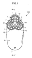
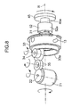
- FIGS. 1 and 2 are a perspective view and a side view of a hair removal apparatus 100 according to a preferred embodiment of the invention, respectively, and FIG. 3 is an exploded perspective view of the hair removal apparatus 100 shown in FIG. 1 .
- FIGS. 4 and 5 are cross-sectional views of the hair removal apparatus 100
- FIG. 6 is a perspective view of a plucking roller 21 of one of epilation units 1.
- FIGS. 7 and 8 are perspective views showing how motive power is generated and transmitted for driving the hair removal apparatus 100
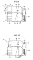
- FIGS. 9 and 10 are side views showing the epilation units 1 under normal conditions and floated conditions, respectively.
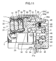
- FIG. 11 is a cross-sectional view corresponding to FIG. 4 showing the epilation unit 1 under the floated conditions.
- the hair removal apparatus 100 is configured to pull out unwanted body hairs, in particular those from arms, legs and underarms.
- the hair removal apparatus 100 includes three epilation units 1, a supportive housing 2 or casing for supporting the three epilation units 1, a motor 3 serving as a power source, a first motive power transmission mechanism 4 for transmitting a rotational driving force generated by the motor 3 to the epilation units 1, and a pair of outer covers 5, 6 incorporating all internal elements of the hair removal apparatus 100 together forming a structure grippable by a single hand.
- the two outer covers 5, 6 are fixed to each other by screws 7.
- There is formed an opening 5a in the outer cover 5 so that the three epilation units 1 are exposed outward toward a skin surface S as shown in FIG. 2 .
- the motor 3 is connected to a battery 9 serving as a power supply.
- the three epilation units 1 are closely located in such a way that central points of the epilation units 1 are positioned at vertices of a generally equilateral triangle in plan view as depicted in FIG. 1 . Also, the three epilation units 1 are disposed to project toward the skin surface S generally by the same amount as depicted in FIG. 2 .
- the hair removal apparatus 100 of this embodiment is configured such that the epilation units 1 can float (i.e., protrude and retract) in a direction generally perpendicular to the skin surface S and/or swing in a direction generally along the skin surface S independently of one another so that the individual epilation units 1 can be held well in close contact with the skin surface S having such bodily features as swells and hollows.
- each of the epilation units 1 includes a rotor 11, a sleeve 12 and a pair of pins 13 serving as a pivotal axis.
- the rotor 11 is configured to rotate on an axis R shown in FIG. 4 due to the rotational driving force transmitted through the first motive power transmission mechanism 4 with the axis R kept generally perpendicular to the skin surface S. Specifically, the axis R of the rotor 11 passes approximately a central point of the plucking roller 21.
- the rotor 11 of each epilation unit 1 includes the aforementioned plucking roller 21, a roller shaft 22, a roller base 23, a protective plate 24 and a second motive power transmission mechanism 25.
- Each of the plucking rollers 21 is supported rotatably on its own axis by the roller shaft 22.
- the plucking roller 21 of each rotor 11 carries a plurality of tweezing mechanisms 21a fitted on a curved outer surface, each tweezing mechanism 21a including a pair of platelike members arranged to extend side by side along a rotating direction of the plucking roller 21 with a narrow gap 21b formed between the platelike members to guide body hairs thereinto as shown in FIG. 6 .
- These tweezing mechanisms 21a are configured to close the gaps 21b when brought into contact with the skin surface S, whereby the tweezing mechanisms 21a grasp the body hairs introduced into the gaps 21b.
- each rotor 11 extends in a direction generally parallel to the skin surface S and each plucking roller 21 supported by the roller shaft 22 rotates on its own axis during epilation.
- the rotating plucking rollers 21 grasp and pull out the body hairs.
- roller base 23 supporting the roller shaft 22 of each rotor 11 is affixed to a later-described roller case 32 by screws 27.
- the protective plates 24 of the rotors 11 lie on areas of the skin surface S with which the individual plucking rollers 21 go into contact.
- the protective plates 24 serve to protect the skin surface S by preventing the tweezing mechanisms 21a from contacting the skin surface S with excessive pressure.
- Each protective plate 24 is affixed to the roller base 23 by screws 28.
- the second motive power transmission mechanism 25 of each rotor 11 is connected to the first motive power transmission mechanism 4 to transmit the rotational driving force supplied therefrom to the plucking roller 21 for rotating the same.
- the second motive power transmission mechanism 25 includes a power input member 31, the aforementioned roller case 32, a crown gear 33 and epilation unit-side gears 34, 35.
- the power input member 31 of each second motive power transmission mechanism 25 is a mechanical element of the epilation unit 1 to which the rotational driving force supplied from the first motive power transmission mechanism 4 is first transmitted.
- Each power input member 31 has a mating part 31a recessed in a U-shaped cross section which can flexibly engage a projecting part 52b of each of later-described cylindrical members 52 of the first motive power transmission mechanism 4. The power input member 31 thus configured turns on the aforementioned axis R due to the rotational driving force input from the first motive power transmission mechanism 4.
- roller case 32 of each second motive power transmission mechanism 25 is joined to the power input member 31 by screws 26, the roller case 32 rotates together with the power input member 31. Also, as the roller base 23 is affixed to the roller case 32 by the screws 27 as mentioned above, the power input member 31, the roller case 32, the roller base 23 and the plucking roller 21 rotate as a single structure on the axis R.
- the crown gear 33 of each epilation unit 1 is fitted with the pair of pins 13. These pins 13 are fitted into pin holes 12a formed in the sleeve 12 and into later-described slots 2a formed in the supportive housing 2, so that the crown gear 33 is a nonrotating element. Further, the crown gear 33 has a face gear portion 33a which meshes with the epilation unit-side gear 34.
- the epilation unit-side gear 34 is pivotably supported by a gear shaft 36 fitted between a side portion of the roller case 32 and a gear cover 38. In the epilation unit 1 thus configured, the epilation unit-side gear 34 turns along the face gear portion 33a of the crown gear 33 when the roller case 32 rotates together with the power input member 31.
- the other epilation unit-side gear 35 mates with the aforementioned epilation unit-side gear 34 and is pivotably supported by a gear shaft 37 fitted on a side portion of the roller base 23.
- This epilation unit-side gear 35 also mates with an unillustrated gear portion formed on an end portion of the plucking roller 21 and thus serves to transmit the rotational driving force to the plucking roller 21 so that the plucking roller 21 can rotate on the roller shaft 22.
- the sleeve 12 of each epilation unit 1 surrounds the plucking roller 21 and projects toward the skin surface S.
- the sleeve 12 is configured such that an outer end 12b thereof placed against the skin surface S becomes flush with an extreme outer part of the plucking roller 21 that is brought into contact with the skin surface S as shown in FIG. 4 .
- the individual sleeves 12 go into contact with the skin surface S together with the plucking rollers 21.
- This arrangement of the embodiment may be modified such that the outer ends 12b of the sleeves 12 slightly project further outward toward the skin surface S than the extreme outer parts of the plucking rollers 21.
- the aforementioned supportive housing 2 has a triple-cup structure for accommodating the three epilation units 1.
- the aforementioned slots 2a in which the pairs of pins 13 of the individual epilation units 1 are fitted are formed in the supportive housing 2 at appropriate points thereof so that each epilation unit 1 can swing in a direction marked by "A" in FIG. 9 with respect to the supportive housing 2.
- the slots 2a in the supportive housing 2 are formed to create some play for the pins 13 of each epilation unit 1 to move along a direction marked by "B" in FIG. 9 so that each epilation unit 1 can float (i.e., protrude and retract) along the B direction with respect to the supportive housing 2.
- This arrangement of the embodiment enables the individual epilation units 1 to float up and down as shown in FIG. 10 while swinging independently of one another.
- the first motive power transmission mechanism 4 includes driving and transmission gears 41-45 and gear shafts 46-49 rotatably supporting the gears 42-45, respectively, which are arranged in this order from a driving side to a driven side.
- the first motive power transmission mechanism 4 further includes a gear cover 51, the aforementioned cylindrical members 52 and compression coil springs 53.
- the driving gear 41 is fitted on a driving shaft 3a of the motor 3.
- the gears 42-44 are rotatably supported by the respective gear shafts 46-48 of which opposite ends are supported by the supportive housing 2 and the gear cover 51.
- the first motive power transmission mechanism 4 thus configured, the motive power of the motor 3 output from the driving shaft 3a is transmitted to the individual epilation units 1 through three driving gears 45.
- the aforementioned gear cover 51 is fixed to an inside of a recessed part 6a of the outer cover 6 by screws 8.
- the three driving gears 45 fitted on the gear shafts 49 which are mounted in the supportive housing 2 are configured to engage the respective cylindrical members 52. Specifically, as gear teeth formed on a curved outer surface of a projecting sleevelike part 45a of each driving gear 45 mesh with gear teeth formed on a curved inner surface of a sleevelike part 52a of the corresponding cylindrical member 52 as shown in FIG. 5 , the motive power of the motor 3 is transmitted to each cylindrical member 52.
- the compression coil spring 53 is fitted in the sleevelike part 52a of the cylindrical member 52 of each epilation unit 1 to produce a biasing force acting on the gear shaft 45 and the cylindrical member 52 in opposite directions, causing both to separate from each other. This configuration makes it possible to easily bring each epilation unit 1 which has retracted into the supportive housing 2 back to an original position.
- Each of the cylindrical members 52 of the first motive power transmission mechanism 4 has the aforementioned projecting part 52b which meshes with the recessed mating part 31a of the corresponding power input member 31.
- the projecting part 52b of each cylindrical member 52 has a generally triangular shape in plan view.
- the mating part 31a of each power input member 31 also has a generally triangular shape in plan view although not illustrated. This arrangement ensures that the epilation units 1 will not easily be disengaged from the supportive housing 2 regardless of floating and/or swinging action of the epilation units 1 relative to the supportive housing 2 (refer to FIG. 11 ).
- the motive power (rotational driving force) produced by the motor 3 is transmitted to the three driving gears 45 through the gears 41-45 of the first motive power transmission mechanism 4 (refer to FIG. 7 ) and then further downstream to the power input members 31 of the epilation units 1 via the respective cylindrical members 52 (refer to FIG. 8 ), thereby causing the rotors 11 of the epilation units 1 to rotate on the respective axes R.
- the cylindrical members 52 of the first motive power transmission mechanism 4 are connected to the power input members 31 with the projecting parts 52b flexibly meshed with the respective mating parts 31a as mentioned above, the cylindrical members 52 and the power input members 31 are securely held in an interconnected state even when the epilation units 1 are making swing motion in the supportive housing 2. Additionally, since the cylindrical members 52 incorporate the compression coil springs 53 for biasing the cylindrical members 52 toward the respective power input members 31, the cylindrical members 52 can float up and down relative to the respective driving gears 45. This structure of the embodiment makes it possible to reliably transmit the motive power (rotational driving force) to the epilation units 1 even when the epilation units 1 swing and float to a great extent relative to the supportive housing 2.
- the epilation unit-side gears 34 built in the rotors 11 mesh with the face gear portions 33a of the respective crown gears 33, the epilation unit-side gears 34 rotate on their own axes when the rotors 11 turn on the respective axes R. Also, as the rotational driving force of the first motive power transmission mechanism 4 is transmitted to the individual plucking rollers 21 via the epilation unit-side gears 34 , 35 , the plucking rollers 21 rotate on the respective roller shafts 22.
- the three epilation units 1 incorporate the rotors 11 of which plucking rollers 21 turn on the respective axes R while rotating on the respective roller shafts 22.
- the hair removal apparatus 100 of the embodiment can pluck the body hairs from the skin.
- the individual epilation units 1 can swing and float independently of one another according to swelling and hollowed features of the skin surface S, the hair removal apparatus 100 can epilate body hairs with the three epilation units 1 held in sufficiently close contact with the skin surface S.
- the hair removal apparatus 100 of the present embodiment is configured such that the three epilation units 1 float, or protrude and retract, independently of one another as much as heights and depths of swells and hollows of the skin surface S as mentioned above, it is possible to pull out body hairs from the skin surface S having swollen and hollowed parts over sufficiently broad areas of contact between the epilation units 1 and the skin surface S.
- the hair removal apparatus 100 provided with the three epilation units 1 can treat an increased epilation area yet preventing a reduction in epilation efficiency.
- the three epilation units 1 are configured to swing independently of one another as mentioned above. Since the individual epilation units 1 swing in appropriate directions so that the epilation units 1 fit swollen and hollowed areas of the skin surface S, it is possible to keep the epilation units 1 in close contact with the skin surface S having swollen and hollowed parts over sufficiently broad skin areas. This structure sufficiently prevents a reduction in epilation area.
- each epilation unit 1 is fitted in the slots 2a formed in the supportive housing 2 as mentioned above.
- This simple structure allows the individual epilation units 1 to float and swing independently of one another with respect to the supportive housing 2.
- each epilation unit 1 is made floatable up and down relative to the supportive housing 2 and the cylindrical member 52 and the power input member 31 are flexibly connected to each other as mentioned above.
- This structure allows each epilation unit 1 to float and swing relative to the supportive housing 2 while transmitting the motive power (rotational driving force) from the first motive power transmission mechanism 4 to the second motive power transmission mechanism 25 in a reliable fashion.
- each epilation unit 1 is biased in the direction toward the skin surface S by the compression coil spring 53 in such a manner that each epilation unit 1 can retract into the supportive housing 2 overwhelming the biasing force of the compression coil spring 53 when the plucking roller 21 is acted upon by a proper level of reaction force from the skin surface S.
- each epilation unit 1 is automatically brought back to the original position by the biasing force of the compression coil spring 53 when the reaction force from the skin surface S is removed.
- the individual sleeves 12 go into contact with the skin surface S together with the plucking rollers 21.
- This arrangement is advantageous for preventing such inconvenience that the hair removal apparatus 100 is led to unintended directions on the skin surface S due to strong contact of only the rotating plucking rollers 21 with the skin, thereby enabling smooth epilation. Additionally, this arrangement of the embodiment serves to alleviate an unpleasant feeling that the user may have when the hair is pulled out of the skin because the sleeves 12 hold the skin tight during epilation.
- the invention has thus been described with reference to the hair removal apparatus 100 of the preferred embodiment provided with the three epilation units 1, the invention is not limited to this embodiment but is similarly applicable to a hair removal apparatus provided with one or two epilation units or more than three epilation units.
- a hair removal apparatus comprises a plurality of extractors each of which rotates on a first rotary axis extending in a direction generally parallel to a skin surface during epilation, each of the extractors having a tweezing mechanism for grasping hairs, and a driver for turning each of the extractors on a second rotary axis which is kept generally perpendicular to the skin surface.
- the plurality of extractors are configured to protrude and retract in a direction generally perpendicular to the skin surface independently of one another, and the hair removal apparatus pulls the grasped hairs out of the skin surface when moved with the extractors held in contact with the skin surface.
- the hair removal apparatus is configured such that the plurality of extractors float, or protrude and retract, independently of one another as much as heights and depths of swells and hollows of the skin surface, it is possible to pull out body hairs from the skin surface having swollen and hollowed parts over sufficiently broad areas of contact between the extractors and the skin surface.
- the hair removal apparatus provided with the plurality of extractors can treat an increased epilation area yet preventing a reduction in epilation efficiency.
- the hair removal apparatus may be configured such that the plurality of extractors are swingable in directions along the skin surface independently of one another while protruding and retracting in the direction generally perpendicular to the skin surface independently of one another.
- the plurality of extractors can swing independently of one another. Since the individual extractors swing in appropriate directions so that the extractors fit swollen and hollowed areas of the skin surface, it is possible to keep the extractors in close contact with the skin surface having swollen and hollowed parts over sufficiently broad skin areas. This structure sufficiently prevents a reduction in epilation area.
- the hair removal apparatus may be configured such that the driver includes a first motive power transmission mechanism connected to a power source, and a plurality of second motive power transmission mechanisms connected to the first motive power transmission mechanism to transmit a driving force supplied therefrom to the individual extractors, wherein each of the extractors and the corresponding second motive power transmission mechanism are assembled to constitute a modular epilation unit.
- the hair removal apparatus may be further provided with a casing for supporting the epilation units, the casing being provided with a pin which is fitted in a slot formed in the casing so that each of the epilation units can protrude and retract, and swing as the pin moves along and turns in the slot.
- the hair removal apparatus may be configured such that the first motive power transmission mechanism has an output portion which is made movable relative to the casing in the direction generally perpendicular to the skin surface, and each of the second motive power transmission mechanisms has an input portion which flexibly meshes with the output portion of the first motive power transmission mechanism.
- This structure allows each epilation unit to float and swing relative to the casing while transmitting motive power (rotational driving force) from the first motive power transmission mechanism to the second motive power transmission mechanisms in a reliable fashion.
- the first motive power transmission mechanism may be provided with a biasing member which biases the output portion of the first motive power transmission mechanism in a direction toward the skin surface.
- each epilation unit can retract into the casing overwhelming a biasing force exerted by the biasing member when the extractor is acted upon by a proper level of reaction force from the skin surface.
- each epilation unit is automatically brought back to an original position by the biasing force of the biasing member when the reaction force from the skin surface is removed.
- the hair removal apparatus may be further provided with a sleeve which surrounds the extractors and projects outward toward the skin surface at least to a point where an outer end of the sleeve becomes flush with an extreme outer part of each of the extractors.
- the sleeve goes into contact with the skin surface together with the extractors.
- This arrangement is advantageous for preventing such inconvenience that the hair removal apparatus is led to unintended directions on the skin surface due to strong contact of only the rotating extractors with the skin, thereby enabling smooth epilation. Additionally, this arrangement serves to alleviate an unpleasant feeling that the user may have when the hair is pulled out of the skin because the sleeves hold the skin tight during epilation.
Landscapes
- Life Sciences & Earth Sciences (AREA)
- Forests & Forestry (AREA)
- Engineering & Computer Science (AREA)
- Mechanical Engineering (AREA)
- Massaging Devices (AREA)
- Hair Curling (AREA)
- Dry Shavers And Clippers (AREA)
- Surgical Instruments (AREA)
- Devices For Medical Bathing And Washing (AREA)
- Removal Of Floating Material (AREA)
- Brushes (AREA)
Abstract
Description
- The present invention relates to a hair removal apparatus for removing unwanted body hair by pulling the hair out of the skin.
- Japanese Unexamined Patent Publication No.
1998-151020 - It has conventionally been desired for the aforementioned type of hair removal apparatuses to ensure an increased contact area between individual extractors and the skin surface yet preventing a reduction in epilation efficiency.
- The present invention is intended to achieve the aforementioned object. Accordingly, it is a specific object of the invention to provide a hair removal apparatus having a plurality of extractors which can treat an increased epilation area yet preventing a reduction in epilation efficiency.
- According to an aspect of the invention, a hair removal apparatus comprises a plurality of extractors each of which rotates on a first rotary axis extending in a direction generally parallel to a skin surface during epilation, each of the extractors having a tweezing mechanism for grasping hairs, and a driver for turning each of the extractors on a second rotary axis which is kept generally perpendicular to the skin surface. The plurality of extractors are configured to protrude and retract in a direction generally perpendicular to the skin surface independently of one another, and the hair removal apparatus pulls the grasped hairs out of the skin surface when moved with the extractors held in contact with the skin surface.
- These and other objects, features and advantages of the invention will become more apparent upon a reading of the following detailed description in conjunction with the accompanying drawings.
-
-
FIG. 1 is a perspective view of a hair removal apparatus according to a preferred embodiment of the invention; -
FIG. 2 is a side view of the hair removal apparatus shown inFIG. 1 ; -
FIG. 3 is an exploded perspective view of the hair removal apparatus shown inFIG. 1 ; -
FIG. 4 is a cross-sectional view of the hair removal apparatus taken along lines IV-IV shown inFIG. 1 ; -
FIG. 5 is a cross-sectional view of the hair removal apparatus taken along lines V-V shown inFIG. 4 ; -
FIG. 6 is a perspective view of a plucking roller of one of epilation units shown inFIG. 4 ; -
FIG. 7 is a perspective view showing how motive power is transmitted by a first motive power transmission mechanism of the hair removal apparatus; -
FIG. 8 is a perspective view showing how the motive power is transmitted by a second motive power transmission mechanism of the hair removal apparatus; -
FIG. 9 is a side view showing the epilation units under normal conditions; -
FIG. 10 is a side view showing the epilation units under floated conditions; and -
FIG. 11 is a cross-sectional view corresponding toFIG. 4 showing one of the epilation units under the floated conditions. - A preferred embodiment of the invention is now described in detail with reference to the accompanying drawings.
-
FIGS. 1 and2 are a perspective view and a side view of ahair removal apparatus 100 according to a preferred embodiment of the invention, respectively, andFIG. 3 is an exploded perspective view of thehair removal apparatus 100 shown inFIG. 1 .FIGS. 4 and5 are cross-sectional views of thehair removal apparatus 100, andFIG. 6 is a perspective view of aplucking roller 21 of one ofepilation units 1.FIGS. 7 and8 are perspective views showing how motive power is generated and transmitted for driving thehair removal apparatus 100 andFIGS. 9 and 10 are side views showing theepilation units 1 under normal conditions and floated conditions, respectively.FIG. 11 is a cross-sectional view corresponding toFIG. 4 showing theepilation unit 1 under the floated conditions. - The
hair removal apparatus 100 is configured to pull out unwanted body hairs, in particular those from arms, legs and underarms. Referring toFIGS. 1 to 3 , thehair removal apparatus 100 includes threeepilation units 1, asupportive housing 2 or casing for supporting the threeepilation units 1, amotor 3 serving as a power source, a first motivepower transmission mechanism 4 for transmitting a rotational driving force generated by themotor 3 to theepilation units 1, and a pair ofouter covers hair removal apparatus 100 together forming a structure grippable by a single hand. The twoouter covers screws 7. There is formed an opening 5a in theouter cover 5 so that the threeepilation units 1 are exposed outward toward a skin surface S as shown inFIG. 2 . Themotor 3 is connected to a battery 9 serving as a power supply. - The three
epilation units 1 are closely located in such a way that central points of theepilation units 1 are positioned at vertices of a generally equilateral triangle in plan view as depicted inFIG. 1 . Also, the threeepilation units 1 are disposed to project toward the skin surface S generally by the same amount as depicted inFIG. 2 . Thehair removal apparatus 100 of this embodiment is configured such that theepilation units 1 can float (i.e., protrude and retract) in a direction generally perpendicular to the skin surface S and/or swing in a direction generally along the skin surface S independently of one another so that theindividual epilation units 1 can be held well in close contact with the skin surface S having such bodily features as swells and hollows. As shown inFIGS. 3 to 5 , each of theepilation units 1 includes arotor 11, asleeve 12 and a pair ofpins 13 serving as a pivotal axis. - The
rotor 11 is configured to rotate on an axis R shown inFIG. 4 due to the rotational driving force transmitted through the first motivepower transmission mechanism 4 with the axis R kept generally perpendicular to the skin surface S. Specifically, the axis R of therotor 11 passes approximately a central point of theplucking roller 21. Therotor 11 of eachepilation unit 1 includes theaforementioned plucking roller 21, aroller shaft 22, aroller base 23, aprotective plate 24 and a second motivepower transmission mechanism 25. - Each of the
plucking rollers 21 is supported rotatably on its own axis by theroller shaft 22. Theplucking roller 21 of eachrotor 11 carries a plurality oftweezing mechanisms 21a fitted on a curved outer surface, eachtweezing mechanism 21a including a pair of platelike members arranged to extend side by side along a rotating direction of theplucking roller 21 with anarrow gap 21b formed between the platelike members to guide body hairs thereinto as shown inFIG. 6 . Thesetweezing mechanisms 21a are configured to close thegaps 21b when brought into contact with the skin surface S, whereby thetweezing mechanisms 21a grasp the body hairs introduced into thegaps 21b. - The
roller shaft 22 of eachrotor 11 extends in a direction generally parallel to the skin surface S and eachplucking roller 21 supported by theroller shaft 22 rotates on its own axis during epilation. When a user moves thehair removal apparatus 100 along the skin surface S, the rotatingplucking rollers 21 grasp and pull out the body hairs. - As shown in
FIG. 5 , theroller base 23 supporting theroller shaft 22 of eachrotor 11 is affixed to a later-describedroller case 32 byscrews 27. - The
protective plates 24 of therotors 11 lie on areas of the skin surface S with which theindividual plucking rollers 21 go into contact. Theprotective plates 24 serve to protect the skin surface S by preventing thetweezing mechanisms 21a from contacting the skin surface S with excessive pressure. Eachprotective plate 24 is affixed to theroller base 23 byscrews 28. - The second motive
power transmission mechanism 25 of eachrotor 11 is connected to the first motivepower transmission mechanism 4 to transmit the rotational driving force supplied therefrom to theplucking roller 21 for rotating the same. As shown inFIG. 4 , the second motivepower transmission mechanism 25 includes apower input member 31, theaforementioned roller case 32, acrown gear 33 and epilation unit-side gears - The
power input member 31 of each second motivepower transmission mechanism 25 is a mechanical element of theepilation unit 1 to which the rotational driving force supplied from the first motivepower transmission mechanism 4 is first transmitted. Eachpower input member 31 has amating part 31a recessed in a U-shaped cross section which can flexibly engage a projectingpart 52b of each of later-describedcylindrical members 52 of the first motivepower transmission mechanism 4. Thepower input member 31 thus configured turns on the aforementioned axis R due to the rotational driving force input from the first motivepower transmission mechanism 4. - As the
roller case 32 of each second motivepower transmission mechanism 25 is joined to thepower input member 31 byscrews 26, theroller case 32 rotates together with thepower input member 31. Also, as theroller base 23 is affixed to theroller case 32 by thescrews 27 as mentioned above, thepower input member 31, theroller case 32, theroller base 23 and theplucking roller 21 rotate as a single structure on the axis R. - The
crown gear 33 of eachepilation unit 1 is fitted with the pair ofpins 13. Thesepins 13 are fitted intopin holes 12a formed in thesleeve 12 and into later-describedslots 2a formed in thesupportive housing 2, so that thecrown gear 33 is a nonrotating element. Further, thecrown gear 33 has aface gear portion 33a which meshes with the epilation unit-side gear 34. The epilation unit-side gear 34 is pivotably supported by agear shaft 36 fitted between a side portion of theroller case 32 and agear cover 38. In theepilation unit 1 thus configured, the epilation unit-side gear 34 turns along theface gear portion 33a of thecrown gear 33 when theroller case 32 rotates together with thepower input member 31. - The other epilation unit-
side gear 35 mates with the aforementioned epilation unit-side gear 34 and is pivotably supported by agear shaft 37 fitted on a side portion of theroller base 23. This epilation unit-side gear 35 also mates with an unillustrated gear portion formed on an end portion of the pluckingroller 21 and thus serves to transmit the rotational driving force to the pluckingroller 21 so that the pluckingroller 21 can rotate on theroller shaft 22. - The
sleeve 12 of eachepilation unit 1 surrounds the pluckingroller 21 and projects toward the skin surface S. In this embodiment, thesleeve 12 is configured such that anouter end 12b thereof placed against the skin surface S becomes flush with an extreme outer part of the pluckingroller 21 that is brought into contact with the skin surface S as shown inFIG. 4 . Thus, theindividual sleeves 12 go into contact with the skin surface S together with the pluckingrollers 21. This arrangement of the embodiment may be modified such that the outer ends 12b of thesleeves 12 slightly project further outward toward the skin surface S than the extreme outer parts of the pluckingrollers 21. - The aforementioned
supportive housing 2 has a triple-cup structure for accommodating the threeepilation units 1. Theaforementioned slots 2a in which the pairs ofpins 13 of theindividual epilation units 1 are fitted are formed in thesupportive housing 2 at appropriate points thereof so that eachepilation unit 1 can swing in a direction marked by "A" inFIG. 9 with respect to thesupportive housing 2. Also, theslots 2a in thesupportive housing 2 are formed to create some play for thepins 13 of eachepilation unit 1 to move along a direction marked by "B" inFIG. 9 so that eachepilation unit 1 can float (i.e., protrude and retract) along the B direction with respect to thesupportive housing 2. This arrangement of the embodiment enables theindividual epilation units 1 to float up and down as shown inFIG. 10 while swinging independently of one another. - Referring to
FIG. 7 , the first motivepower transmission mechanism 4 includes driving and transmission gears 41-45 and gear shafts 46-49 rotatably supporting the gears 42-45, respectively, which are arranged in this order from a driving side to a driven side. The first motivepower transmission mechanism 4 further includes agear cover 51, the aforementionedcylindrical members 52 and compression coil springs 53. - The
driving gear 41 is fitted on a drivingshaft 3a of themotor 3. The gears 42-44 are rotatably supported by the respective gear shafts 46-48 of which opposite ends are supported by thesupportive housing 2 and thegear cover 51. With the first motivepower transmission mechanism 4 thus configured, the motive power of themotor 3 output from the drivingshaft 3a is transmitted to theindividual epilation units 1 through three driving gears 45. Theaforementioned gear cover 51 is fixed to an inside of a recessedpart 6a of theouter cover 6 byscrews 8. - The three driving gears 45 fitted on the
gear shafts 49 which are mounted in thesupportive housing 2 are configured to engage the respectivecylindrical members 52. Specifically, as gear teeth formed on a curved outer surface of a projectingsleevelike part 45a of each drivinggear 45 mesh with gear teeth formed on a curved inner surface of asleevelike part 52a of the correspondingcylindrical member 52 as shown inFIG. 5 , the motive power of themotor 3 is transmitted to eachcylindrical member 52. Thecompression coil spring 53 is fitted in thesleevelike part 52a of thecylindrical member 52 of eachepilation unit 1 to produce a biasing force acting on thegear shaft 45 and thecylindrical member 52 in opposite directions, causing both to separate from each other. This configuration makes it possible to easily bring eachepilation unit 1 which has retracted into thesupportive housing 2 back to an original position. - Each of the
cylindrical members 52 of the first motivepower transmission mechanism 4 has the aforementioned projectingpart 52b which meshes with the recessedmating part 31a of the correspondingpower input member 31. The projectingpart 52b of eachcylindrical member 52 has a generally triangular shape in plan view. Themating part 31a of eachpower input member 31 also has a generally triangular shape in plan view although not illustrated. This arrangement ensures that theepilation units 1 will not easily be disengaged from thesupportive housing 2 regardless of floating and/or swinging action of theepilation units 1 relative to the supportive housing 2 (refer toFIG. 11 ). - In the
hair removal apparatus 100 thus configured, the motive power (rotational driving force) produced by themotor 3 is transmitted to the three drivinggears 45 through the gears 41-45 of the first motive power transmission mechanism 4 (refer toFIG. 7 ) and then further downstream to thepower input members 31 of theepilation units 1 via the respective cylindrical members 52 (refer toFIG. 8 ), thereby causing therotors 11 of theepilation units 1 to rotate on the respective axes R. - Since the
cylindrical members 52 of the first motivepower transmission mechanism 4 are connected to thepower input members 31 with the projectingparts 52b flexibly meshed with therespective mating parts 31a as mentioned above, thecylindrical members 52 and thepower input members 31 are securely held in an interconnected state even when theepilation units 1 are making swing motion in thesupportive housing 2. Additionally, since thecylindrical members 52 incorporate the compression coil springs 53 for biasing thecylindrical members 52 toward the respectivepower input members 31, thecylindrical members 52 can float up and down relative to the respective driving gears 45. This structure of the embodiment makes it possible to reliably transmit the motive power (rotational driving force) to theepilation units 1 even when theepilation units 1 swing and float to a great extent relative to thesupportive housing 2. - Since the epilation unit-side gears 34 built in the
rotors 11 mesh with theface gear portions 33a of the respective crown gears 33, the epilation unit-side gears 34 rotate on their own axes when therotors 11 turn on the respective axes R. Also, as the rotational driving force of the first motivepower transmission mechanism 4 is transmitted to theindividual plucking rollers 21 via the epilation unit-side gears 34 , 35 , the pluckingrollers 21 rotate on therespective roller shafts 22. - As thus far described, the three
epilation units 1 incorporate therotors 11 of which pluckingrollers 21 turn on the respective axes R while rotating on therespective roller shafts 22. With this arrangement, thehair removal apparatus 100 of the embodiment can pluck the body hairs from the skin. As theindividual epilation units 1 can swing and float independently of one another according to swelling and hollowed features of the skin surface S, thehair removal apparatus 100 can epilate body hairs with the threeepilation units 1 held in sufficiently close contact with the skin surface S. - Since the
hair removal apparatus 100 of the present embodiment is configured such that the threeepilation units 1 float, or protrude and retract, independently of one another as much as heights and depths of swells and hollows of the skin surface S as mentioned above, it is possible to pull out body hairs from the skin surface S having swollen and hollowed parts over sufficiently broad areas of contact between theepilation units 1 and the skin surface S. In this structure, thehair removal apparatus 100 provided with the threeepilation units 1 can treat an increased epilation area yet preventing a reduction in epilation efficiency. - In this embodiment, the three
epilation units 1 are configured to swing independently of one another as mentioned above. Since theindividual epilation units 1 swing in appropriate directions so that theepilation units 1 fit swollen and hollowed areas of the skin surface S, it is possible to keep theepilation units 1 in close contact with the skin surface S having swollen and hollowed parts over sufficiently broad skin areas. This structure sufficiently prevents a reduction in epilation area. - In the
hair removal apparatus 100 of the foregoing embodiment, thepins 13 of eachepilation unit 1 are fitted in theslots 2a formed in thesupportive housing 2 as mentioned above. This simple structure allows theindividual epilation units 1 to float and swing independently of one another with respect to thesupportive housing 2. - In this embodiment, the
cylindrical member 52 of eachepilation unit 1 is made floatable up and down relative to thesupportive housing 2 and thecylindrical member 52 and thepower input member 31 are flexibly connected to each other as mentioned above. This structure allows eachepilation unit 1 to float and swing relative to thesupportive housing 2 while transmitting the motive power (rotational driving force) from the first motivepower transmission mechanism 4 to the second motivepower transmission mechanism 25 in a reliable fashion. - Furthermore, the
cylindrical member 52 of eachepilation unit 1 is biased in the direction toward the skin surface S by thecompression coil spring 53 in such a manner that eachepilation unit 1 can retract into thesupportive housing 2 overwhelming the biasing force of thecompression coil spring 53 when the pluckingroller 21 is acted upon by a proper level of reaction force from the skin surface S. In this structure, eachepilation unit 1 is automatically brought back to the original position by the biasing force of thecompression coil spring 53 when the reaction force from the skin surface S is removed. - In this embodiment, the
individual sleeves 12 go into contact with the skin surface S together with the pluckingrollers 21. This arrangement is advantageous for preventing such inconvenience that thehair removal apparatus 100 is led to unintended directions on the skin surface S due to strong contact of only therotating plucking rollers 21 with the skin, thereby enabling smooth epilation. Additionally, this arrangement of the embodiment serves to alleviate an unpleasant feeling that the user may have when the hair is pulled out of the skin because thesleeves 12 hold the skin tight during epilation. - While the invention has thus been described with reference to the
hair removal apparatus 100 of the preferred embodiment provided with the threeepilation units 1, the invention is not limited to this embodiment but is similarly applicable to a hair removal apparatus provided with one or two epilation units or more than three epilation units. - The invention has thus far been described in detail, by way of example, with reference to the preferred embodiment thereof.
- In summary, a hair removal apparatus comprises a plurality of extractors each of which rotates on a first rotary axis extending in a direction generally parallel to a skin surface during epilation, each of the extractors having a tweezing mechanism for grasping hairs, and a driver for turning each of the extractors on a second rotary axis which is kept generally perpendicular to the skin surface. The plurality of extractors are configured to protrude and retract in a direction generally perpendicular to the skin surface independently of one another, and the hair removal apparatus pulls the grasped hairs out of the skin surface when moved with the extractors held in contact with the skin surface.
- Since the hair removal apparatus is configured such that the plurality of extractors float, or protrude and retract, independently of one another as much as heights and depths of swells and hollows of the skin surface, it is possible to pull out body hairs from the skin surface having swollen and hollowed parts over sufficiently broad areas of contact between the extractors and the skin surface. In this structure, the hair removal apparatus provided with the plurality of extractors can treat an increased epilation area yet preventing a reduction in epilation efficiency.
- The hair removal apparatus may be configured such that the plurality of extractors are swingable in directions along the skin surface independently of one another while protruding and retracting in the direction generally perpendicular to the skin surface independently of one another.
- In the hair removal apparatus thus configured, the plurality of extractors can swing independently of one another. Since the individual extractors swing in appropriate directions so that the extractors fit swollen and hollowed areas of the skin surface, it is possible to keep the extractors in close contact with the skin surface having swollen and hollowed parts over sufficiently broad skin areas. This structure sufficiently prevents a reduction in epilation area.
- The hair removal apparatus may be configured such that the driver includes a first motive power transmission mechanism connected to a power source, and a plurality of second motive power transmission mechanisms connected to the first motive power transmission mechanism to transmit a driving force supplied therefrom to the individual extractors, wherein each of the extractors and the corresponding second motive power transmission mechanism are assembled to constitute a modular epilation unit. The hair removal apparatus may be further provided with a casing for supporting the epilation units, the casing being provided with a pin which is fitted in a slot formed in the casing so that each of the epilation units can protrude and retract, and swing as the pin moves along and turns in the slot.
- According to this feature, it is possible to allow the individual epilation units to float and swing independently of one another with respect to the casing with a simple structure using pins and slots.
- The hair removal apparatus may be configured such that the first motive power transmission mechanism has an output portion which is made movable relative to the casing in the direction generally perpendicular to the skin surface, and each of the second motive power transmission mechanisms has an input portion which flexibly meshes with the output portion of the first motive power transmission mechanism.
- This structure allows each epilation unit to float and swing relative to the casing while transmitting motive power (rotational driving force) from the first motive power transmission mechanism to the second motive power transmission mechanisms in a reliable fashion.
- The first motive power transmission mechanism may be provided with a biasing member which biases the output portion of the first motive power transmission mechanism in a direction toward the skin surface.
- According to this feature, each epilation unit can retract into the casing overwhelming a biasing force exerted by the biasing member when the extractor is acted upon by a proper level of reaction force from the skin surface. In this structure, each epilation unit is automatically brought back to an original position by the biasing force of the biasing member when the reaction force from the skin surface is removed.
- The hair removal apparatus may be further provided with a sleeve which surrounds the extractors and projects outward toward the skin surface at least to a point where an outer end of the sleeve becomes flush with an extreme outer part of each of the extractors.
- In this structure, the sleeve goes into contact with the skin surface together with the extractors. This arrangement is advantageous for preventing such inconvenience that the hair removal apparatus is led to unintended directions on the skin surface due to strong contact of only the rotating extractors with the skin, thereby enabling smooth epilation. Additionally, this arrangement serves to alleviate an unpleasant feeling that the user may have when the hair is pulled out of the skin because the sleeves hold the skin tight during epilation.
- This application is based on patent application No.
2007-43360 - As this invention may be embodied in several forms without departing from the spirit of essential characteristics thereof, the present embodiment is therefore illustrative and not restrictive, since the scope of the invention is defined by the appended claims rather than by the description preceding them, and all changes that fall within metes and bounds of the claims, or equivalence of such metes and bounds are therefore intended to embraced by the claims.
Claims (6)
- A hair removal apparatus comprising:a plurality of extractors each of which rotates on a first rotary axis extending in a direction generally parallel to a skin surface during epilation, each of the extractors having a tweezing mechanism for grasping hairs; anda driver for turning each of the extractors on a second rotary axis which is kept generally perpendicular to the skin surface;wherein the plurality of extractors are configured to protrude and retract in a direction generally perpendicular to the skin surface independently of one another, and the hair removal apparatus pulls the grasped hairs out of the skin surface when moved with the extractors held in contact with the skin surface.
- The hair removal apparatus according to claim 1, wherein the plurality of extractors are swingable in directions along the skin surface independently of one another while protruding and retracting in the direction generally perpendicular to the skin surface independently of one another.
- The hair removal apparatus according to claim 1 or 2, wherein the driver includes:a first motive power transmission mechanism connected to a power source; anda plurality of second motive power transmission mechanisms connected to the first motive power transmission mechanism to transmit a driving force supplied therefrom to the individual extractors;wherein each of the extractors and the corresponding second motive power transmission mechanism are assembled to constitute a modular epilation unit;the hair removal apparatus further comprising:a casing for supporting the epilation units, the casing being provided with a pin which is fitted in a slot formed in the casing so that each of the epilation units can protrude and retract, and swing as the pin moves along and turns in the slot.
- The hair removal apparatus according to claim 3, wherein the first motive power transmission mechanism has an output portion which is made movable relative to the casing in the direction generally perpendicular to the skin surface, and each of the second motive power transmission mechanisms has an input portion which flexibly meshes with the output portion of the first motive power transmission mechanism.
- The hair removal apparatus according to claim 4, wherein the first motive power transmission mechanism is provided with a biasing member which biases the output portion of the first motive power transmission mechanism in a direction toward the skin surface.
- The hair removal apparatus according to one of claims 1 to 5, further comprising a sleeve which surrounds the extractors and projects outward toward the skin surface at least to a point where an outer end of the sleeve becomes flush with an extreme outer part of each of the extractors.
Applications Claiming Priority (1)
| Application Number | Priority Date | Filing Date | Title |
|---|---|---|---|
| JP2007043360A JP4265666B2 (en) | 2007-02-23 | 2007-02-23 | Hair removal equipment |
Publications (2)
| Publication Number | Publication Date |
|---|---|
| EP1961329A1 true EP1961329A1 (en) | 2008-08-27 |
| EP1961329B1 EP1961329B1 (en) | 2010-06-09 |
Family
ID=39356787
Family Applications (1)
| Application Number | Title | Priority Date | Filing Date |
|---|---|---|---|
| EP08003213A Not-in-force EP1961329B1 (en) | 2007-02-23 | 2008-02-21 | Hair removal apparatus |
Country Status (9)
| Country | Link |
|---|---|
| US (1) | US20080294176A1 (en) |
| EP (1) | EP1961329B1 (en) |
| JP (1) | JP4265666B2 (en) |
| KR (1) | KR100960435B1 (en) |
| CN (2) | CN201150331Y (en) |
| AT (1) | ATE470368T1 (en) |
| DE (1) | DE602008001449D1 (en) |
| HK (1) | HK1116022A1 (en) |
| RU (1) | RU2373816C1 (en) |
Cited By (2)
| Publication number | Priority date | Publication date | Assignee | Title |
|---|---|---|---|---|
| EP3183993A1 (en) * | 2015-12-22 | 2017-06-28 | Braun GmbH | Epilator |
| US10779626B2 (en) | 2015-12-22 | 2020-09-22 | Braun Gmbh | Skin treatment apparatus |
Families Citing this family (12)
| Publication number | Priority date | Publication date | Assignee | Title |
|---|---|---|---|---|
| JP2004350764A (en) * | 2003-05-27 | 2004-12-16 | Izumi Products Co | Rechargeable electric shaver |
| JP4265666B2 (en) * | 2007-02-23 | 2009-05-20 | パナソニック電工株式会社 | Hair removal equipment |
| JP4462344B2 (en) * | 2007-12-25 | 2010-05-12 | パナソニック電工株式会社 | Electric hair remover |
| JP4613948B2 (en) * | 2007-12-25 | 2011-01-19 | パナソニック電工株式会社 | Electric hair remover |
| US9027251B2 (en) | 2009-04-29 | 2015-05-12 | Spectrum Brands, Inc. | Rotary electric shaver |
| AT508911B1 (en) | 2009-12-02 | 2011-05-15 | Siemens Ag | CONVERTER WITH POWER FACTOR CORRECTION |
| AT508912B1 (en) | 2009-12-02 | 2011-05-15 | Siemens Ag | FLOW CONVERTER WITH POWER FACTOR CORRECTION |
| RU2633194C2 (en) * | 2013-04-16 | 2017-10-11 | БРАУН ГмбХ | Head of epilator and epilator |
| BR112015008478B1 (en) * | 2013-11-05 | 2020-11-03 | Koninklijke Philips N.V. | personal care device |
| WO2017079199A1 (en) * | 2015-11-03 | 2017-05-11 | Spectrum Brands, Inc. | Hair grooming appliance |
| CN105747467B (en) * | 2016-04-20 | 2022-09-09 | 温州市日增电器有限公司 | Hair remover |
| EP3689180B1 (en) * | 2017-10-06 | 2021-11-03 | Braun GmbH | Epilator |
Citations (4)
| Publication number | Priority date | Publication date | Assignee | Title |
|---|---|---|---|---|
| EP0417935A1 (en) * | 1989-09-14 | 1991-03-20 | Crestmoore Ltd. | Depilatory device |
| US5163288A (en) * | 1991-03-05 | 1992-11-17 | Moshe Doley | Rotary head multi-spring hair removal device |
| FR2678822A1 (en) | 1991-07-10 | 1993-01-15 | Mazza Catherine | Apparatus for removing hair from the skin of humans |
| US6163288A (en) | 1997-10-09 | 2000-12-19 | Kabushiki Kaisha Toshiba | Digital-to-analog converter in which an analog output of low order bits is attenuated, and added to an analog output of high order bits |
Family Cites Families (37)
| Publication number | Priority date | Publication date | Assignee | Title |
|---|---|---|---|---|
| US2164425A (en) * | 1937-07-09 | 1939-07-04 | Remington Rand Inc | Multiple head dry shaver |
| US3715803A (en) * | 1971-02-16 | 1973-02-13 | T Tyler | Rotary dry shaver with tiltable shear plates |
| US4001932A (en) * | 1972-07-14 | 1977-01-11 | Bissell Inc. | Rotary shaver with shear plate rotation preventing means |
| JPS5719084Y2 (en) * | 1976-05-26 | 1982-04-21 | ||
| DE3610736A1 (en) * | 1986-03-29 | 1987-10-01 | Braun Ag | ELECTRIC SHAVER WITH A PIVOTING SHEAR HEAD SYSTEM |
| US4875288A (en) * | 1987-09-02 | 1989-10-24 | The Gillette Company | Shaving device |
| NL8800405A (en) | 1988-02-18 | 1989-09-18 | Philips Nv | SHAVER. |
| IL90433A (en) * | 1989-05-26 | 1993-04-04 | Yair Daar Moshav Galia And Shi | Depilatory device |
| US5100414A (en) | 1991-03-05 | 1992-03-31 | Moshe Dolev | Rotary head multi-spring hair removal device |
| EP0613345A1 (en) * | 1991-11-20 | 1994-09-07 | PAYER ELEKTROPRODUKTE GESELLSCHAFT mbH | Epilator |
| US5217469A (en) * | 1992-01-27 | 1993-06-08 | Moshe Dolev | Rotary head spring-loaded tweezer hair removal device |
| DE4244164C2 (en) * | 1992-12-24 | 1995-09-07 | Braun Ag | Dry shaver with a pivoting long hair trimmer |
| DE19521585A1 (en) * | 1995-06-14 | 1996-12-19 | Braun Ag | Device for plucking hair from human skin |
| DE69615771T2 (en) * | 1995-08-28 | 2002-07-11 | Matsushita Electric Works Ltd | hand-held depilating |
| JP3923535B2 (en) * | 1996-08-06 | 2007-06-06 | ブラウン ゲーエムベーハー | Rotating cylinder for hair removal equipment |
| US5899910A (en) * | 1996-09-17 | 1999-05-04 | Etman; Sameer A. | Direct acting cam gripping mechanism |
| JP3640113B2 (en) | 1996-11-26 | 2005-04-20 | 松下電工株式会社 | Hair removal equipment |
| US6212776B1 (en) * | 1997-02-25 | 2001-04-10 | Izuma Products Company | Electric shaver |
| KR100543557B1 (en) * | 1997-10-30 | 2007-04-25 | 산요덴키가부시키가이샤 | Electric shaver |
| US6436106B2 (en) * | 1998-07-09 | 2002-08-20 | Soft Lines, Ltd. | Hair removal device with disc, vibration, and light assemblies |
| JP3849345B2 (en) * | 1999-04-23 | 2006-11-22 | 松下電工株式会社 | Hair removal equipment |
| DE19932884C1 (en) * | 1999-07-16 | 2000-08-10 | Braun Gmbh | Depilation apparatus for plucking hair out of human skin comprises housing in which depilatory head incorporating plucking components and activated by a drive device is located |
| US6585743B2 (en) * | 2000-06-09 | 2003-07-01 | Moshe Dolev | Hair depilating device utilizing mechanism to spirally align coupled-tweezer elements |
| JP2002058887A (en) * | 2000-08-22 | 2002-02-26 | Matsushita Electric Works Ltd | Edge for electric razor |
| JP2002159327A (en) * | 2000-11-27 | 2002-06-04 | Matsushita Electric Works Ltd | Hair remover |
| CN1293998C (en) * | 2000-12-22 | 2007-01-10 | 皇家菲利浦电子有限公司 | Auxiliary part for an electric shaver |
| TW557208B (en) * | 2001-05-28 | 2003-10-11 | Matsushita Electric Works Ltd | Molting apparatus |
| US8627573B2 (en) * | 2002-10-05 | 2014-01-14 | Braun Gmbh | Hair-removing device |
| JP4552646B2 (en) * | 2004-12-16 | 2010-09-29 | パナソニック電工株式会社 | Hair removal equipment |
| JP2006175072A (en) * | 2004-12-22 | 2006-07-06 | Matsushita Electric Works Ltd | Depilation device |
| JP4756908B2 (en) * | 2005-05-18 | 2011-08-24 | 株式会社泉精器製作所 | Rotary electric razor |
| JP4229091B2 (en) * | 2005-05-31 | 2009-02-25 | パナソニック電工株式会社 | Hair treatment equipment |
| JP4919255B2 (en) * | 2005-10-25 | 2012-04-18 | 株式会社泉精器製作所 | Rotary electric razor |
| JP2007151925A (en) * | 2005-12-07 | 2007-06-21 | Izumi Products Co | Rotary electric razor |
| JP2007260172A (en) * | 2006-03-28 | 2007-10-11 | Matsushita Electric Works Ltd | Depilator |
| JP4127299B2 (en) * | 2006-06-16 | 2008-07-30 | 松下電工株式会社 | Hair clipper |
| JP4265666B2 (en) * | 2007-02-23 | 2009-05-20 | パナソニック電工株式会社 | Hair removal equipment |
-
2007
- 2007-02-23 JP JP2007043360A patent/JP4265666B2/en not_active Expired - Fee Related
-
2008
- 2008-02-12 US US12/029,690 patent/US20080294176A1/en not_active Abandoned
- 2008-02-21 CN CNU2008200066475U patent/CN201150331Y/en not_active Expired - Lifetime
- 2008-02-21 DE DE602008001449T patent/DE602008001449D1/en active Active
- 2008-02-21 EP EP08003213A patent/EP1961329B1/en not_active Not-in-force
- 2008-02-21 KR KR1020080015901A patent/KR100960435B1/en not_active IP Right Cessation
- 2008-02-21 AT AT08003213T patent/ATE470368T1/en not_active IP Right Cessation
- 2008-02-21 CN CN200810081914XA patent/CN101248924B/en not_active Expired - Fee Related
- 2008-02-22 RU RU2008106940/12A patent/RU2373816C1/en not_active IP Right Cessation
- 2008-10-24 HK HK08111724.2A patent/HK1116022A1/en not_active IP Right Cessation
Patent Citations (4)
| Publication number | Priority date | Publication date | Assignee | Title |
|---|---|---|---|---|
| EP0417935A1 (en) * | 1989-09-14 | 1991-03-20 | Crestmoore Ltd. | Depilatory device |
| US5163288A (en) * | 1991-03-05 | 1992-11-17 | Moshe Doley | Rotary head multi-spring hair removal device |
| FR2678822A1 (en) | 1991-07-10 | 1993-01-15 | Mazza Catherine | Apparatus for removing hair from the skin of humans |
| US6163288A (en) | 1997-10-09 | 2000-12-19 | Kabushiki Kaisha Toshiba | Digital-to-analog converter in which an analog output of low order bits is attenuated, and added to an analog output of high order bits |
Cited By (5)
| Publication number | Priority date | Publication date | Assignee | Title |
|---|---|---|---|---|
| EP3183993A1 (en) * | 2015-12-22 | 2017-06-28 | Braun GmbH | Epilator |
| WO2017109650A1 (en) * | 2015-12-22 | 2017-06-29 | Braun Gmbh | Epilator |
| CN108366660A (en) * | 2015-12-22 | 2018-08-03 | 博朗有限公司 | Grainer |
| US10779626B2 (en) | 2015-12-22 | 2020-09-22 | Braun Gmbh | Skin treatment apparatus |
| CN108366660B (en) * | 2015-12-22 | 2021-05-14 | 博朗有限公司 | Depilator |
Also Published As
| Publication number | Publication date |
|---|---|
| KR100960435B1 (en) | 2010-05-28 |
| EP1961329B1 (en) | 2010-06-09 |
| CN101248924B (en) | 2010-06-02 |
| CN101248924A (en) | 2008-08-27 |
| ATE470368T1 (en) | 2010-06-15 |
| RU2008106940A (en) | 2009-08-27 |
| JP4265666B2 (en) | 2009-05-20 |
| RU2373816C1 (en) | 2009-11-27 |
| KR20080078579A (en) | 2008-08-27 |
| JP2008206543A (en) | 2008-09-11 |
| US20080294176A1 (en) | 2008-11-27 |
| DE602008001449D1 (en) | 2010-07-22 |
| HK1116022A1 (en) | 2008-12-19 |
| CN201150331Y (en) | 2008-11-19 |
Similar Documents
| Publication | Publication Date | Title |
|---|---|---|
| EP1961329A1 (en) | Hair removal apparatus | |
| US20080208190A1 (en) | Hair removal apparatus | |
| US7797834B2 (en) | Shaving device with a pivotable shaving head carrying an actively driven cutting member | |
| JP4120247B2 (en) | Beauty equipment | |
| CN101732093B (en) | Micromanipulator for enterocoelia minimally invasive surgery | |
| US8296954B2 (en) | Shaver having spaces for collecting cut-off hairs | |
| EP2568850B1 (en) | A drive system | |
| US9009978B2 (en) | Shaver having spaces for collecting cut-off hairs | |
| JP6751913B2 (en) | Attachment of electric hair cutting device | |
| EP0549051A1 (en) | Depilation apparatus with twisting action | |
| EP3104739B1 (en) | Epilator with separable pair of heads | |
| CN112402017A (en) | Surgical robot tail end execution device and surgical robot tail end driving mechanism | |
| JP3804356B2 (en) | Beauty equipment | |
| JP3931713B2 (en) | Hair removal equipment | |
| JP2823081B2 (en) | Rotary electric razor | |
| JP2004222742A (en) | Small electric appliance | |
| JP2001204540A (en) | Depilator | |
| JP2009000280A (en) | Depilation device | |
| JPH0999184A (en) | Power scissors | |
| JPH11299531A (en) | Depilating device |
Legal Events
| Date | Code | Title | Description |
|---|---|---|---|
| PUAI | Public reference made under article 153(3) epc to a published international application that has entered the european phase |
Free format text: ORIGINAL CODE: 0009012 |
|
| AK | Designated contracting states |
Kind code of ref document: A1 Designated state(s): AT BE BG CH CY CZ DE DK EE ES FI FR GB GR HR HU IE IS IT LI LT LU LV MC MT NL NO PL PT RO SE SI SK TR |
|
| AX | Request for extension of the european patent |
Extension state: AL BA MK RS |
|
| RAP1 | Party data changed (applicant data changed or rights of an application transferred) |
Owner name: PANASONIC ELECTRIC WORKS CO., LTD. |
|
| 17P | Request for examination filed |
Effective date: 20090122 |
|
| AKX | Designation fees paid |
Designated state(s): AT BE BG CH CY CZ DE DK EE ES FI FR GB GR HR HU IE IS IT LI LT LU LV MC MT NL NO PL PT RO SE SI SK TR |
|
| GRAP | Despatch of communication of intention to grant a patent |
Free format text: ORIGINAL CODE: EPIDOSNIGR1 |
|
| GRAS | Grant fee paid |
Free format text: ORIGINAL CODE: EPIDOSNIGR3 |
|
| GRAA | (expected) grant |
Free format text: ORIGINAL CODE: 0009210 |
|
| RIN1 | Information on inventor provided before grant (corrected) |
Inventor name: MURAKI, KENICHI Inventor name: HASHIGUCHI, TETSURO |
|
| AK | Designated contracting states |
Kind code of ref document: B1 Designated state(s): AT BE BG CH CY CZ DE DK EE ES FI FR GB GR HR HU IE IS IT LI LT LU LV MC MT NL NO PL PT RO SE SI SK TR |
|
| REG | Reference to a national code |
Ref country code: CH Ref legal event code: EP |
|
| REG | Reference to a national code |
Ref country code: IE Ref legal event code: FG4D |
|
| REF | Corresponds to: |
Ref document number: 602008001449 Country of ref document: DE Date of ref document: 20100722 Kind code of ref document: P |
|
| REG | Reference to a national code |
Ref country code: NL Ref legal event code: VDEP Effective date: 20100609 |
|
| PG25 | Lapsed in a contracting state [announced via postgrant information from national office to epo] |
Ref country code: LT Free format text: LAPSE BECAUSE OF FAILURE TO SUBMIT A TRANSLATION OF THE DESCRIPTION OR TO PAY THE FEE WITHIN THE PRESCRIBED TIME-LIMIT Effective date: 20100609 Ref country code: SE Free format text: LAPSE BECAUSE OF FAILURE TO SUBMIT A TRANSLATION OF THE DESCRIPTION OR TO PAY THE FEE WITHIN THE PRESCRIBED TIME-LIMIT Effective date: 20100609 Ref country code: NO Free format text: LAPSE BECAUSE OF FAILURE TO SUBMIT A TRANSLATION OF THE DESCRIPTION OR TO PAY THE FEE WITHIN THE PRESCRIBED TIME-LIMIT Effective date: 20100909 |
|
| LTIE | Lt: invalidation of european patent or patent extension |
Effective date: 20100609 |
|
| PG25 | Lapsed in a contracting state [announced via postgrant information from national office to epo] |
Ref country code: LV Free format text: LAPSE BECAUSE OF FAILURE TO SUBMIT A TRANSLATION OF THE DESCRIPTION OR TO PAY THE FEE WITHIN THE PRESCRIBED TIME-LIMIT Effective date: 20100609 Ref country code: HR Free format text: LAPSE BECAUSE OF FAILURE TO SUBMIT A TRANSLATION OF THE DESCRIPTION OR TO PAY THE FEE WITHIN THE PRESCRIBED TIME-LIMIT Effective date: 20100609 Ref country code: FI Free format text: LAPSE BECAUSE OF FAILURE TO SUBMIT A TRANSLATION OF THE DESCRIPTION OR TO PAY THE FEE WITHIN THE PRESCRIBED TIME-LIMIT Effective date: 20100609 Ref country code: AT Free format text: LAPSE BECAUSE OF FAILURE TO SUBMIT A TRANSLATION OF THE DESCRIPTION OR TO PAY THE FEE WITHIN THE PRESCRIBED TIME-LIMIT Effective date: 20100609 Ref country code: SI Free format text: LAPSE BECAUSE OF FAILURE TO SUBMIT A TRANSLATION OF THE DESCRIPTION OR TO PAY THE FEE WITHIN THE PRESCRIBED TIME-LIMIT Effective date: 20100609 |
|
| PG25 | Lapsed in a contracting state [announced via postgrant information from national office to epo] |
Ref country code: PL Free format text: LAPSE BECAUSE OF FAILURE TO SUBMIT A TRANSLATION OF THE DESCRIPTION OR TO PAY THE FEE WITHIN THE PRESCRIBED TIME-LIMIT Effective date: 20100609 Ref country code: CY Free format text: LAPSE BECAUSE OF FAILURE TO SUBMIT A TRANSLATION OF THE DESCRIPTION OR TO PAY THE FEE WITHIN THE PRESCRIBED TIME-LIMIT Effective date: 20100609 |
|
| PG25 | Lapsed in a contracting state [announced via postgrant information from national office to epo] |
Ref country code: EE Free format text: LAPSE BECAUSE OF FAILURE TO SUBMIT A TRANSLATION OF THE DESCRIPTION OR TO PAY THE FEE WITHIN THE PRESCRIBED TIME-LIMIT Effective date: 20100609 Ref country code: NL Free format text: LAPSE BECAUSE OF FAILURE TO SUBMIT A TRANSLATION OF THE DESCRIPTION OR TO PAY THE FEE WITHIN THE PRESCRIBED TIME-LIMIT Effective date: 20100609 |
|
| PG25 | Lapsed in a contracting state [announced via postgrant information from national office to epo] |
Ref country code: SK Free format text: LAPSE BECAUSE OF FAILURE TO SUBMIT A TRANSLATION OF THE DESCRIPTION OR TO PAY THE FEE WITHIN THE PRESCRIBED TIME-LIMIT Effective date: 20100609 Ref country code: RO Free format text: LAPSE BECAUSE OF FAILURE TO SUBMIT A TRANSLATION OF THE DESCRIPTION OR TO PAY THE FEE WITHIN THE PRESCRIBED TIME-LIMIT Effective date: 20100609 Ref country code: CZ Free format text: LAPSE BECAUSE OF FAILURE TO SUBMIT A TRANSLATION OF THE DESCRIPTION OR TO PAY THE FEE WITHIN THE PRESCRIBED TIME-LIMIT Effective date: 20100609 Ref country code: BE Free format text: LAPSE BECAUSE OF FAILURE TO SUBMIT A TRANSLATION OF THE DESCRIPTION OR TO PAY THE FEE WITHIN THE PRESCRIBED TIME-LIMIT Effective date: 20100609 Ref country code: PT Free format text: LAPSE BECAUSE OF FAILURE TO SUBMIT A TRANSLATION OF THE DESCRIPTION OR TO PAY THE FEE WITHIN THE PRESCRIBED TIME-LIMIT Effective date: 20101011 Ref country code: IS Free format text: LAPSE BECAUSE OF FAILURE TO SUBMIT A TRANSLATION OF THE DESCRIPTION OR TO PAY THE FEE WITHIN THE PRESCRIBED TIME-LIMIT Effective date: 20101009 |
|
| PG25 | Lapsed in a contracting state [announced via postgrant information from national office to epo] |
Ref country code: IT Free format text: LAPSE BECAUSE OF FAILURE TO SUBMIT A TRANSLATION OF THE DESCRIPTION OR TO PAY THE FEE WITHIN THE PRESCRIBED TIME-LIMIT Effective date: 20100609 |
|
| PLBE | No opposition filed within time limit |
Free format text: ORIGINAL CODE: 0009261 |
|
| STAA | Information on the status of an ep patent application or granted ep patent |
Free format text: STATUS: NO OPPOSITION FILED WITHIN TIME LIMIT |
|
| PG25 | Lapsed in a contracting state [announced via postgrant information from national office to epo] |
Ref country code: DK Free format text: LAPSE BECAUSE OF FAILURE TO SUBMIT A TRANSLATION OF THE DESCRIPTION OR TO PAY THE FEE WITHIN THE PRESCRIBED TIME-LIMIT Effective date: 20100609 |
|
| PG25 | Lapsed in a contracting state [announced via postgrant information from national office to epo] |
Ref country code: GR Free format text: LAPSE BECAUSE OF FAILURE TO SUBMIT A TRANSLATION OF THE DESCRIPTION OR TO PAY THE FEE WITHIN THE PRESCRIBED TIME-LIMIT Effective date: 20100910 |
|
| REG | Reference to a national code |
Ref country code: DE Ref legal event code: R097 Ref document number: 602008001449 Country of ref document: DE Effective date: 20110309 |
|
| PG25 | Lapsed in a contracting state [announced via postgrant information from national office to epo] |
Ref country code: MC Free format text: LAPSE BECAUSE OF NON-PAYMENT OF DUE FEES Effective date: 20110228 |
|
| REG | Reference to a national code |
Ref country code: FR Ref legal event code: ST Effective date: 20111102 |
|
| REG | Reference to a national code |
Ref country code: IE Ref legal event code: MM4A |
|
| PG25 | Lapsed in a contracting state [announced via postgrant information from national office to epo] |
Ref country code: MT Free format text: LAPSE BECAUSE OF FAILURE TO SUBMIT A TRANSLATION OF THE DESCRIPTION OR TO PAY THE FEE WITHIN THE PRESCRIBED TIME-LIMIT Effective date: 20100609 |
|
| PG25 | Lapsed in a contracting state [announced via postgrant information from national office to epo] |
Ref country code: FR Free format text: LAPSE BECAUSE OF NON-PAYMENT OF DUE FEES Effective date: 20110228 Ref country code: IE Free format text: LAPSE BECAUSE OF NON-PAYMENT OF DUE FEES Effective date: 20110221 |
|
| PGFP | Annual fee paid to national office [announced via postgrant information from national office to epo] |
Ref country code: DE Payment date: 20120215 Year of fee payment: 5 |
|
| PGFP | Annual fee paid to national office [announced via postgrant information from national office to epo] |
Ref country code: GB Payment date: 20120215 Year of fee payment: 5 |
|
| REG | Reference to a national code |
Ref country code: CH Ref legal event code: PL |
|
| PG25 | Lapsed in a contracting state [announced via postgrant information from national office to epo] |
Ref country code: CH Free format text: LAPSE BECAUSE OF NON-PAYMENT OF DUE FEES Effective date: 20120229 Ref country code: LI Free format text: LAPSE BECAUSE OF NON-PAYMENT OF DUE FEES Effective date: 20120229 |
|
| PG25 | Lapsed in a contracting state [announced via postgrant information from national office to epo] |
Ref country code: LU Free format text: LAPSE BECAUSE OF NON-PAYMENT OF DUE FEES Effective date: 20110221 |
|
| PG25 | Lapsed in a contracting state [announced via postgrant information from national office to epo] |
Ref country code: TR Free format text: LAPSE BECAUSE OF FAILURE TO SUBMIT A TRANSLATION OF THE DESCRIPTION OR TO PAY THE FEE WITHIN THE PRESCRIBED TIME-LIMIT Effective date: 20100609 Ref country code: BG Free format text: LAPSE BECAUSE OF FAILURE TO SUBMIT A TRANSLATION OF THE DESCRIPTION OR TO PAY THE FEE WITHIN THE PRESCRIBED TIME-LIMIT Effective date: 20100909 |
|
| GBPC | Gb: european patent ceased through non-payment of renewal fee |
Effective date: 20130221 |
|
| PG25 | Lapsed in a contracting state [announced via postgrant information from national office to epo] |
Ref country code: HU Free format text: LAPSE BECAUSE OF FAILURE TO SUBMIT A TRANSLATION OF THE DESCRIPTION OR TO PAY THE FEE WITHIN THE PRESCRIBED TIME-LIMIT Effective date: 20100609 Ref country code: ES Free format text: LAPSE BECAUSE OF FAILURE TO SUBMIT A TRANSLATION OF THE DESCRIPTION OR TO PAY THE FEE WITHIN THE PRESCRIBED TIME-LIMIT Effective date: 20100920 |
|
| REG | Reference to a national code |
Ref country code: DE Ref legal event code: R119 Ref document number: 602008001449 Country of ref document: DE Effective date: 20130903 |
|
| PG25 | Lapsed in a contracting state [announced via postgrant information from national office to epo] |
Ref country code: GB Free format text: LAPSE BECAUSE OF NON-PAYMENT OF DUE FEES Effective date: 20130221 Ref country code: DE Free format text: LAPSE BECAUSE OF NON-PAYMENT OF DUE FEES Effective date: 20130903 |