EP1937380B1 - Kabelloser Videospielcontroller und Verfahren zum Betreiben des kabellosen Videospielcontrollers - Google Patents
Kabelloser Videospielcontroller und Verfahren zum Betreiben des kabellosen Videospielcontrollers Download PDFInfo
- Publication number
- EP1937380B1 EP1937380B1 EP06814475A EP06814475A EP1937380B1 EP 1937380 B1 EP1937380 B1 EP 1937380B1 EP 06814475 A EP06814475 A EP 06814475A EP 06814475 A EP06814475 A EP 06814475A EP 1937380 B1 EP1937380 B1 EP 1937380B1
- Authority
- EP
- European Patent Office
- Prior art keywords
- controller
- sound
- image
- game controller
- game
- Prior art date
- Legal status (The legal status is an assumption and is not a legal conclusion. Google has not performed a legal analysis and makes no representation as to the accuracy of the status listed.)
- Active
Links
- 238000000034 method Methods 0.000 title claims abstract description 79
- 230000003993 interaction Effects 0.000 claims abstract description 13
- 230000033001 locomotion Effects 0.000 claims description 54
- 239000013598 vector Substances 0.000 claims description 18
- 230000005484 gravity Effects 0.000 claims description 6
- 239000007787 solid Substances 0.000 claims description 3
- 230000008859 change Effects 0.000 abstract description 18
- 238000004590 computer program Methods 0.000 abstract description 17
- 230000000694 effects Effects 0.000 abstract description 15
- 238000012545 processing Methods 0.000 description 47
- 230000008569 process Effects 0.000 description 28
- 230000003044 adaptive effect Effects 0.000 description 17
- 238000010586 diagram Methods 0.000 description 17
- 238000013459 approach Methods 0.000 description 15
- 238000004891 communication Methods 0.000 description 15
- 238000001914 filtration Methods 0.000 description 14
- 238000009877 rendering Methods 0.000 description 13
- 230000005236 sound signal Effects 0.000 description 13
- 230000005540 biological transmission Effects 0.000 description 10
- 230000006870 function Effects 0.000 description 10
- 238000005286 illumination Methods 0.000 description 9
- 230000002452 interceptive effect Effects 0.000 description 9
- 230000004044 response Effects 0.000 description 9
- 238000000926 separation method Methods 0.000 description 9
- 230000000875 corresponding effect Effects 0.000 description 8
- 239000000463 material Substances 0.000 description 8
- 230000003287 optical effect Effects 0.000 description 8
- 230000009471 action Effects 0.000 description 7
- 230000000903 blocking effect Effects 0.000 description 6
- 238000004422 calculation algorithm Methods 0.000 description 6
- 238000005516 engineering process Methods 0.000 description 6
- 101000893549 Homo sapiens Growth/differentiation factor 15 Proteins 0.000 description 5
- 101000692878 Homo sapiens Regulator of MON1-CCZ1 complex Proteins 0.000 description 5
- 102100026436 Regulator of MON1-CCZ1 complex Human genes 0.000 description 5
- 238000004364 calculation method Methods 0.000 description 5
- 230000007246 mechanism Effects 0.000 description 5
- 102000008482 12E7 Antigen Human genes 0.000 description 4
- 108010020567 12E7 Antigen Proteins 0.000 description 4
- 239000003086 colorant Substances 0.000 description 4
- 238000001514 detection method Methods 0.000 description 4
- 239000004579 marble Substances 0.000 description 4
- 238000001228 spectrum Methods 0.000 description 4
- 239000000872 buffer Substances 0.000 description 3
- 230000001276 controlling effect Effects 0.000 description 3
- 229920001821 foam rubber Polymers 0.000 description 3
- 230000009466 transformation Effects 0.000 description 3
- 238000004458 analytical method Methods 0.000 description 2
- 230000008901 benefit Effects 0.000 description 2
- 230000015572 biosynthetic process Effects 0.000 description 2
- 238000007418 data mining Methods 0.000 description 2
- 238000013500 data storage Methods 0.000 description 2
- 230000001934 delay Effects 0.000 description 2
- 230000001066 destructive effect Effects 0.000 description 2
- 238000007667 floating Methods 0.000 description 2
- 238000012880 independent component analysis Methods 0.000 description 2
- 238000012544 monitoring process Methods 0.000 description 2
- 238000000844 transformation Methods 0.000 description 2
- 230000007704 transition Effects 0.000 description 2
- 230000000007 visual effect Effects 0.000 description 2
- 238000012935 Averaging Methods 0.000 description 1
- 241000425932 Buddleja globosa Species 0.000 description 1
- 102100032912 CD44 antigen Human genes 0.000 description 1
- 101100130502 Caenorhabditis elegans mics-1 gene Proteins 0.000 description 1
- 101000822695 Clostridium perfringens (strain 13 / Type A) Small, acid-soluble spore protein C1 Proteins 0.000 description 1
- 101000655262 Clostridium perfringens (strain 13 / Type A) Small, acid-soluble spore protein C2 Proteins 0.000 description 1
- 101000868273 Homo sapiens CD44 antigen Proteins 0.000 description 1
- 101000655256 Paraclostridium bifermentans Small, acid-soluble spore protein alpha Proteins 0.000 description 1
- 101000655264 Paraclostridium bifermentans Small, acid-soluble spore protein beta Proteins 0.000 description 1
- 230000001133 acceleration Effects 0.000 description 1
- 230000002238 attenuated effect Effects 0.000 description 1
- 238000013477 bayesian statistics method Methods 0.000 description 1
- 230000006399 behavior Effects 0.000 description 1
- 230000003139 buffering effect Effects 0.000 description 1
- 238000006243 chemical reaction Methods 0.000 description 1
- 230000002596 correlated effect Effects 0.000 description 1
- 230000001419 dependent effect Effects 0.000 description 1
- 238000011161 development Methods 0.000 description 1
- 230000018109 developmental process Effects 0.000 description 1
- 238000003708 edge detection Methods 0.000 description 1
- 230000008451 emotion Effects 0.000 description 1
- 230000007613 environmental effect Effects 0.000 description 1
- 238000004880 explosion Methods 0.000 description 1
- 230000001815 facial effect Effects 0.000 description 1
- 230000008921 facial expression Effects 0.000 description 1
- 239000007850 fluorescent dye Substances 0.000 description 1
- 239000003292 glue Substances 0.000 description 1
- 238000003384 imaging method Methods 0.000 description 1
- 239000004973 liquid crystal related substance Substances 0.000 description 1
- 230000004807 localization Effects 0.000 description 1
- 239000011159 matrix material Substances 0.000 description 1
- 238000005259 measurement Methods 0.000 description 1
- 239000002184 metal Substances 0.000 description 1
- 238000012986 modification Methods 0.000 description 1
- 230000004048 modification Effects 0.000 description 1
- 238000012806 monitoring device Methods 0.000 description 1
- 230000036651 mood Effects 0.000 description 1
- 230000002093 peripheral effect Effects 0.000 description 1
- 239000004033 plastic Substances 0.000 description 1
- 229920000642 polymer Polymers 0.000 description 1
- 238000012805 post-processing Methods 0.000 description 1
- 230000001902 propagating effect Effects 0.000 description 1
- 238000013139 quantization Methods 0.000 description 1
- 230000002441 reversible effect Effects 0.000 description 1
- 238000005096 rolling process Methods 0.000 description 1
- 238000005070 sampling Methods 0.000 description 1
- 230000011218 segmentation Effects 0.000 description 1
- 238000004088 simulation Methods 0.000 description 1
- 230000001360 synchronised effect Effects 0.000 description 1
- 238000013519 translation Methods 0.000 description 1
- 230000001960 triggered effect Effects 0.000 description 1
- 201000009482 yaws Diseases 0.000 description 1
Images


Classifications
-
- A—HUMAN NECESSITIES
- A63—SPORTS; GAMES; AMUSEMENTS
- A63F—CARD, BOARD, OR ROULETTE GAMES; INDOOR GAMES USING SMALL MOVING PLAYING BODIES; VIDEO GAMES; GAMES NOT OTHERWISE PROVIDED FOR
- A63F13/00—Video games, i.e. games using an electronically generated display having two or more dimensions
- A63F13/40—Processing input control signals of video game devices, e.g. signals generated by the player or derived from the environment
- A63F13/42—Processing input control signals of video game devices, e.g. signals generated by the player or derived from the environment by mapping the input signals into game commands, e.g. mapping the displacement of a stylus on a touch screen to the steering angle of a virtual vehicle
-
- A—HUMAN NECESSITIES
- A63—SPORTS; GAMES; AMUSEMENTS
- A63F—CARD, BOARD, OR ROULETTE GAMES; INDOOR GAMES USING SMALL MOVING PLAYING BODIES; VIDEO GAMES; GAMES NOT OTHERWISE PROVIDED FOR
- A63F13/00—Video games, i.e. games using an electronically generated display having two or more dimensions
-
- A—HUMAN NECESSITIES
- A63—SPORTS; GAMES; AMUSEMENTS
- A63F—CARD, BOARD, OR ROULETTE GAMES; INDOOR GAMES USING SMALL MOVING PLAYING BODIES; VIDEO GAMES; GAMES NOT OTHERWISE PROVIDED FOR
- A63F13/00—Video games, i.e. games using an electronically generated display having two or more dimensions
- A63F13/20—Input arrangements for video game devices
- A63F13/21—Input arrangements for video game devices characterised by their sensors, purposes or types
- A63F13/211—Input arrangements for video game devices characterised by their sensors, purposes or types using inertial sensors, e.g. accelerometers or gyroscopes
-
- A—HUMAN NECESSITIES
- A63—SPORTS; GAMES; AMUSEMENTS
- A63F—CARD, BOARD, OR ROULETTE GAMES; INDOOR GAMES USING SMALL MOVING PLAYING BODIES; VIDEO GAMES; GAMES NOT OTHERWISE PROVIDED FOR
- A63F13/00—Video games, i.e. games using an electronically generated display having two or more dimensions
- A63F13/20—Input arrangements for video game devices
- A63F13/21—Input arrangements for video game devices characterised by their sensors, purposes or types
- A63F13/213—Input arrangements for video game devices characterised by their sensors, purposes or types comprising photodetecting means, e.g. cameras, photodiodes or infrared cells
-
- A—HUMAN NECESSITIES
- A63—SPORTS; GAMES; AMUSEMENTS
- A63F—CARD, BOARD, OR ROULETTE GAMES; INDOOR GAMES USING SMALL MOVING PLAYING BODIES; VIDEO GAMES; GAMES NOT OTHERWISE PROVIDED FOR
- A63F13/00—Video games, i.e. games using an electronically generated display having two or more dimensions
- A63F13/20—Input arrangements for video game devices
- A63F13/21—Input arrangements for video game devices characterised by their sensors, purposes or types
- A63F13/215—Input arrangements for video game devices characterised by their sensors, purposes or types comprising means for detecting acoustic signals, e.g. using a microphone
-
- A—HUMAN NECESSITIES
- A63—SPORTS; GAMES; AMUSEMENTS
- A63F—CARD, BOARD, OR ROULETTE GAMES; INDOOR GAMES USING SMALL MOVING PLAYING BODIES; VIDEO GAMES; GAMES NOT OTHERWISE PROVIDED FOR
- A63F13/00—Video games, i.e. games using an electronically generated display having two or more dimensions
- A63F13/20—Input arrangements for video game devices
- A63F13/21—Input arrangements for video game devices characterised by their sensors, purposes or types
- A63F13/219—Input arrangements for video game devices characterised by their sensors, purposes or types for aiming at specific areas on the display, e.g. light-guns
-
- A—HUMAN NECESSITIES
- A63—SPORTS; GAMES; AMUSEMENTS
- A63F—CARD, BOARD, OR ROULETTE GAMES; INDOOR GAMES USING SMALL MOVING PLAYING BODIES; VIDEO GAMES; GAMES NOT OTHERWISE PROVIDED FOR
- A63F13/00—Video games, i.e. games using an electronically generated display having two or more dimensions
- A63F13/50—Controlling the output signals based on the game progress
- A63F13/54—Controlling the output signals based on the game progress involving acoustic signals, e.g. for simulating revolutions per minute [RPM] dependent engine sounds in a driving game or reverberation against a virtual wall
-
- A—HUMAN NECESSITIES
- A63—SPORTS; GAMES; AMUSEMENTS
- A63F—CARD, BOARD, OR ROULETTE GAMES; INDOOR GAMES USING SMALL MOVING PLAYING BODIES; VIDEO GAMES; GAMES NOT OTHERWISE PROVIDED FOR
- A63F13/00—Video games, i.e. games using an electronically generated display having two or more dimensions
- A63F13/60—Generating or modifying game content before or while executing the game program, e.g. authoring tools specially adapted for game development or game-integrated level editor
- A63F13/65—Generating or modifying game content before or while executing the game program, e.g. authoring tools specially adapted for game development or game-integrated level editor automatically by game devices or servers from real world data, e.g. measurement in live racing competition
- A63F13/655—Generating or modifying game content before or while executing the game program, e.g. authoring tools specially adapted for game development or game-integrated level editor automatically by game devices or servers from real world data, e.g. measurement in live racing competition by importing photos, e.g. of the player
-
- F—MECHANICAL ENGINEERING; LIGHTING; HEATING; WEAPONS; BLASTING
- F41—WEAPONS
- F41A—FUNCTIONAL FEATURES OR DETAILS COMMON TO BOTH SMALLARMS AND ORDNANCE, e.g. CANNONS; MOUNTINGS FOR SMALLARMS OR ORDNANCE
- F41A33/00—Adaptations for training; Gun simulators
- F41A33/02—Light- or radiation-emitting guns ; Light- or radiation-sensitive guns; Cartridges carrying light emitting sources, e.g. laser
-
- F—MECHANICAL ENGINEERING; LIGHTING; HEATING; WEAPONS; BLASTING
- F41—WEAPONS
- F41J—TARGETS; TARGET RANGES; BULLET CATCHERS
- F41J5/00—Target indicating systems; Target-hit or score detecting systems
- F41J5/02—Photo-electric hit-detector systems
-
- G—PHYSICS
- G06—COMPUTING; CALCULATING OR COUNTING
- G06F—ELECTRIC DIGITAL DATA PROCESSING
- G06F3/00—Input arrangements for transferring data to be processed into a form capable of being handled by the computer; Output arrangements for transferring data from processing unit to output unit, e.g. interface arrangements
- G06F3/01—Input arrangements or combined input and output arrangements for interaction between user and computer
- G06F3/03—Arrangements for converting the position or the displacement of a member into a coded form
- G06F3/0304—Detection arrangements using opto-electronic means
- G06F3/0325—Detection arrangements using opto-electronic means using a plurality of light emitters or reflectors or a plurality of detectors forming a reference frame from which to derive the orientation of the object, e.g. by triangulation or on the basis of reference deformation in the picked up image
-
- A—HUMAN NECESSITIES
- A63—SPORTS; GAMES; AMUSEMENTS
- A63F—CARD, BOARD, OR ROULETTE GAMES; INDOOR GAMES USING SMALL MOVING PLAYING BODIES; VIDEO GAMES; GAMES NOT OTHERWISE PROVIDED FOR
- A63F13/00—Video games, i.e. games using an electronically generated display having two or more dimensions
- A63F13/80—Special adaptations for executing a specific game genre or game mode
- A63F13/837—Shooting of targets
-
- A—HUMAN NECESSITIES
- A63—SPORTS; GAMES; AMUSEMENTS
- A63F—CARD, BOARD, OR ROULETTE GAMES; INDOOR GAMES USING SMALL MOVING PLAYING BODIES; VIDEO GAMES; GAMES NOT OTHERWISE PROVIDED FOR
- A63F2300/00—Features of games using an electronically generated display having two or more dimensions, e.g. on a television screen, showing representations related to the game
- A63F2300/10—Features of games using an electronically generated display having two or more dimensions, e.g. on a television screen, showing representations related to the game characterized by input arrangements for converting player-generated signals into game device control signals
- A63F2300/105—Features of games using an electronically generated display having two or more dimensions, e.g. on a television screen, showing representations related to the game characterized by input arrangements for converting player-generated signals into game device control signals using inertial sensors, e.g. accelerometers, gyroscopes
-
- A—HUMAN NECESSITIES
- A63—SPORTS; GAMES; AMUSEMENTS
- A63F—CARD, BOARD, OR ROULETTE GAMES; INDOOR GAMES USING SMALL MOVING PLAYING BODIES; VIDEO GAMES; GAMES NOT OTHERWISE PROVIDED FOR
- A63F2300/00—Features of games using an electronically generated display having two or more dimensions, e.g. on a television screen, showing representations related to the game
- A63F2300/10—Features of games using an electronically generated display having two or more dimensions, e.g. on a television screen, showing representations related to the game characterized by input arrangements for converting player-generated signals into game device control signals
- A63F2300/1081—Input via voice recognition
-
- A—HUMAN NECESSITIES
- A63—SPORTS; GAMES; AMUSEMENTS
- A63F—CARD, BOARD, OR ROULETTE GAMES; INDOOR GAMES USING SMALL MOVING PLAYING BODIES; VIDEO GAMES; GAMES NOT OTHERWISE PROVIDED FOR
- A63F2300/00—Features of games using an electronically generated display having two or more dimensions, e.g. on a television screen, showing representations related to the game
- A63F2300/10—Features of games using an electronically generated display having two or more dimensions, e.g. on a television screen, showing representations related to the game characterized by input arrangements for converting player-generated signals into game device control signals
- A63F2300/1087—Features of games using an electronically generated display having two or more dimensions, e.g. on a television screen, showing representations related to the game characterized by input arrangements for converting player-generated signals into game device control signals comprising photodetecting means, e.g. a camera
-
- A—HUMAN NECESSITIES
- A63—SPORTS; GAMES; AMUSEMENTS
- A63F—CARD, BOARD, OR ROULETTE GAMES; INDOOR GAMES USING SMALL MOVING PLAYING BODIES; VIDEO GAMES; GAMES NOT OTHERWISE PROVIDED FOR
- A63F2300/00—Features of games using an electronically generated display having two or more dimensions, e.g. on a television screen, showing representations related to the game
- A63F2300/60—Methods for processing data by generating or executing the game program
- A63F2300/6045—Methods for processing data by generating or executing the game program for mapping control signals received from the input arrangement into game commands
-
- A—HUMAN NECESSITIES
- A63—SPORTS; GAMES; AMUSEMENTS
- A63F—CARD, BOARD, OR ROULETTE GAMES; INDOOR GAMES USING SMALL MOVING PLAYING BODIES; VIDEO GAMES; GAMES NOT OTHERWISE PROVIDED FOR
- A63F2300/00—Features of games using an electronically generated display having two or more dimensions, e.g. on a television screen, showing representations related to the game
- A63F2300/60—Methods for processing data by generating or executing the game program
- A63F2300/6063—Methods for processing data by generating or executing the game program for sound processing
- A63F2300/6081—Methods for processing data by generating or executing the game program for sound processing generating an output signal, e.g. under timing constraints, for spatialization
-
- A—HUMAN NECESSITIES
- A63—SPORTS; GAMES; AMUSEMENTS
- A63F—CARD, BOARD, OR ROULETTE GAMES; INDOOR GAMES USING SMALL MOVING PLAYING BODIES; VIDEO GAMES; GAMES NOT OTHERWISE PROVIDED FOR
- A63F2300/00—Features of games using an electronically generated display having two or more dimensions, e.g. on a television screen, showing representations related to the game
- A63F2300/60—Methods for processing data by generating or executing the game program
- A63F2300/69—Involving elements of the real world in the game world, e.g. measurement in live races, real video
- A63F2300/695—Imported photos, e.g. of the player
-
- A—HUMAN NECESSITIES
- A63—SPORTS; GAMES; AMUSEMENTS
- A63F—CARD, BOARD, OR ROULETTE GAMES; INDOOR GAMES USING SMALL MOVING PLAYING BODIES; VIDEO GAMES; GAMES NOT OTHERWISE PROVIDED FOR
- A63F2300/00—Features of games using an electronically generated display having two or more dimensions, e.g. on a television screen, showing representations related to the game
- A63F2300/80—Features of games using an electronically generated display having two or more dimensions, e.g. on a television screen, showing representations related to the game specially adapted for executing a specific type of game
- A63F2300/8076—Shooting
Definitions
- Example gaming platforms include the Sony Playstation or Sony Playstation2 (PS2), each of which is sold in the form of a game console.
- the game console is designed to connect to a monitor (usually a television) and enable user interaction through handheld controllers.
- the game console is designed with specialized processing hardware, including a CPU, a graphics synthesizer for processing intensive graphics operations, a vector unit for performing geometry transformations, and other glue hardware, firmware, and software.
- the game console is further designed with an optical disc tray for receiving game compact discs for local play through the game console. Online gaming is also possible, wherein a user can interactively play against or with other users over the Internet.
- EP-A 1411461 discloses a user-controlled device such as a mouse for sending control signals to an electronic appliance, such as a computer.
- the device includes input buttons and is movable in three-dimensional space.
- the device sends control signals that are correlated with its position to the computer.
- a MEMS acceleration sensor may be used to detect 3-D movement of the device, and a microcontroller then processes the output of the sensor to generate the control signals.
- EP-A 1411461 discloses an input device for providing position and orientation information with six degrees of freedom for use in manipulating a real or virtual three-dimensional object.
- the device includes a handle with a plate attached to an upper portion thereof.
- a set of LEDs or other light sources Associated with an upper planar surface of the plate is a set of LEDs or other light sources arranged in a designated pattern.
- a camera detects light from the light sources in order to determine the position, e.g., X, Y and Z positional parameters, and orientation, e.g., roll, pitch and yaw rotational parameters, of the input device.
- Control software running on a computer system may be used to detect and localize the light sources that are visible in a given image generated by the camera, to associate each of the light sources with a corresponding label, to determine the position and orientation information from the positions of the light sources in the image, and to communicate the position and orientation information to at least one application running on the computer system.
- a computer input device featuring a set of light emitting diodes viewed by a camera for tracking the position and orientation of the device and to encode the actuation of some of the device switches using some LEDs set on and off according to the switches state.
- a wireless pointing device featuring an accelerometer, two visible light LEDs and one infrared LED. The visible light LEDs are used to provide status feedback to the user of the device. The infrared LED is used for tracking the position using cameras.
- the device is connected via a radiofrequency transmitter to a remote computer.
- Figure 1 illustrates an interactive game setup having an image capture device.
- Figure 2 illustrates a method for ascertaining a pointing direction of an object placed in front of an image capture device.
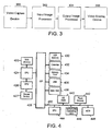
- Figure 3 is a block diagram of an exemplary user input system for interaction with an object on a graphical display.
- Figure 4 is a simplified block diagram of a computer processing system.
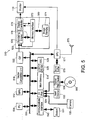
- Figure 5 is a block diagram of a configuration of the components of a video game console adapted for use with a manipulated object serving as an alternative input device.
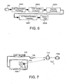
- Figure 6 is a block diagram showing the functional blocks used to track and discriminate a pixel group corresponding to the user input device as it is being manipulated by the user.
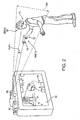
- Figure 7 is a schematic diagram of an example of a deformable user input device.
- Figure 8 shows an exemplary application in which a user is manipulating deformable object
- Figure 9 shows an exemplary deformable object 900 in the form of a basketball
- Figure 10 shows deformable object having a light emitting diode layer (LED) beneath an outer layer.
- LED light emitting diode
- Figure 11 shows an exemplary deformable object in the shape of a football.
- Figure 12 shows an exemplary application for deformable object in which the deformable object in the form of a basketball in use by a user.
- Figure 13 shows a toy gun having a trigger and a trigger sensor.
- Figure 14 shows a toy baseball bat.
- Figure 15 shows a monitor having an image capture unit and a sound capture unit.
- Figure 16 illustrates sound capture units when confronted with two sound sources.
- Figure 17 illustrates the processing of sound A and sound B using a triangulation algorithm so that direction selection can occur.
- Figure 18 illustrates a computing system that may be used in conjunction with an image-sound capture device.
- Figure 19 illustrates an exemplary audio monitor including at least four microphones.
- Figure 20 shows a simplified schematic diagram illustrating an array beam-forming module.
- Figure 21 shows a high level schematic diagram illustrating a blind source separation scheme for separating the noise and source signal components of an audio signal.
- Figure 22 is a schematic diagram illustrating a microphone array framework that incorporates adaptive noise cancellation.
- Figure 23 shows an exemplary toy gun having a trigger and a trigger sensor for interfacing with an audio monitor.
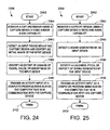
- Figures 24 and 25 show flowcharts for interfacing with a computer program using video capture and audio monitoring, respectively.
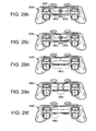
- Figures 26 and 27 show plan and rear elevation views, respectively, of an exemplary controller for interacting with the image capture device of Figure 1 .
- Figures 28 and 29a show plan and rear elevation views, respectively, of a controller having a rectangular configuration of LEDs.
- Figure 29b shows a rear elevation view of a controller incorporates LEDs, a speaker, and a microphone.
- Figure 29c shows a rear elevation view of a controller having LEDs in a rectangular configuration along with centrally located speaker on a rear panel thereof.
- Figure 29d shows a rear elevation view of controller having five LEDs arranged in an arc formation.
- Figure 29e shows a rear elevation view of a controller having LEDs arranged in a wide rectangular configuration.
- Figure 29f shows a controller having six LEDs arranged in a cluster.
- Figure 30 shows flowchart depicting an exemplary procedure for determining what player corresponds to a particular controller when using an image capture device.
- Figure 31 shows a flowchart representing an exemplary procedure for identifying an orientation of a controller using an image capture device.
- Figure 32 shows a flowchart representing an exemplary procedure for identifying an orientation of a controller using an image capture device.
- Figure 33 shows controller having an interface containing a number of controls and a motion sensing device.
- Figure 34 shows a flowchart depicting an exemplary procedure communicating movement of controller to a computer program.
- a computer or gaming system having a video camera and/or audio sensing capability can process image and audio data and identify various actions taking place in a zone of focus for the sensors. Such actions typically include manipulation of an object or creation of sounds, either by voice or by manipulating an object. Examples include pulling the trigger on a toy gun or moving or deforming an object.
- the present technology further provides the additional functionality of sensing and determining an intensity amount associated with these actions. For example, how hard the trigger is pulled, to, what extent is the object deformed, or how tightly is the baseball bat gripped. Using this additional parameter, video game manufacturers and others in fields relating to man-machine interactivity can greatly enhance the user experience. Specific examples of such are described below.
- game controller enhancements to provide increased interactivity between a game controller and a game or other application.
- Such enhancements include providing a plurality of LEDs on the game controller which are viewable by a video capture and processing system, allowing the video game or other application to identify the location, movement, or orientation of the game controller with respect to a video capture device.
- a game controller having sound capture or sound or ultrasonic generation capability for accepting voice commands or communications with other users, and for providing communication between the controller and a base unit.
- FIG. 1 illustrates an interactive game setup 100.
- the interactive game setup 100 includes a computer 102, also referred to herein as "console,” that may be coupled to a display screen 110.
- An image capture device 105 may be placed on top of the display screen 110 and coupled to the computer 102.
- Computer 102 may be a gaming system console which allows users to play video games and interface with the video games through controllers 108.
- the image capture device 105 is shown placed on top of the display screen 110, but it should be understood that the image, capture device 105 can be placed in any other proximate location that will allow it to capture images that are located about in front of the display screen 110.
- Image capture device 105 can be as simple as a standard web cam or can include more advanced technology. Image capture device 105 may be capable of capturing images, digitizing the images, and communicating the image data back to the computer 102. In some cases, the image capture device will have logic integrated therein for performing the digitizing and in another example the image capture device 105 will simply transmit an wog video signal to the computer 102 for digitizing. In either case, she image capture device 105 may be capable of capturing either color or black and white images of any object located in front of the image capture device 105.
- Figure 2 illustrates an exemplary computer 102 for processing image data provided by the image capture device 105 to ascertain a pointing direction of an object placed in front of the image capture device 105.
- the computer 102 may be connected to the image capture device 105.
- the image capture device 105 may be designed to focus onto a capture region 105a.
- a person 112 may be intending to interact with a computer program being executed by the computer 102.
- the computer program in this example, may be a video game which may be rendered and displayed by the display screen 110.
- the video game is a target shooting game in which the person 112 wishes to aim at a target and earn points commensurate with his or her performance.
- an image 112' of the person 112 may also be placed on the display screen 110 during game play.
- the person's image 112' may be omitted from the display screen, depending on the particular device under control or game being played.
- the user experience may be enhanced by illustrating an image 112' of the person 112 during the target shooting exercise to present more reality during game play.
- a feature of the target shooting game may be the ability for person 112 to point or direct an object 124 at particular interactive graphics on the display screen 110.
- the person 112 will hold the object 124 with his or her hand 122.
- the hand 122 will be directionally pointed toward the display screen 110.
- the image capture device 105 will art this point, analyze the digital image capture of the person 112 to determine the location of the person's 112 head 120, and the location of the person's 112 hand 122.
- the person's 112 hand may be extended in front of his body and the image capture device will identify the object 124 when examining the captured digital image.
- the captured digital image will also be examined by code executed at the computer 102 to ascertain the location of the person's 112 head 120.
- Head tracking may be completed with a combination of a template matching (for speed performance), coupled to a face detection code.
- the face detection code will essentially identify the location of the user's face by locating the user's eyes and other facial features.
- the object 124 will, in one example, have an identifier which may be color or lights (e.g., light emitting diodes "LEDs") coupled to the object so that the program analyzing the captured digital image will easily identify the location of the object 124.
- an identifier which may be color or lights (e.g., light emitting diodes "LEDs" coupled to the object so that the program analyzing the captured digital image will easily identify the location of the object 124.
- the computer program will perform computations to determine a relative angle from the image capture device position, and between the detected object 124, and the head 120.
- the relative position of the object 124 and the head 120 will be calculated relative to the image capture device 105. This will produce two angle parameters (theta ⁇ and phi ⁇ ).
- the azimuth angle ⁇ will define the horizontal positioning between the head 120 and the object 124 along an X axis.
- the phi angle ⁇ will produce the altitude angle which is the relative angle between the height of the head 120 and the height of the hand 122.
- an initial calibration operation may be performed before a gaming operation begins to calibrate the object's pointing location on the display screen 110. For instance, the user may be prompted to calibrate the pointing algorithm by having the user point the object 124 at a specific location on the display screen 110.
- the computer 102 will be able to calculate the azimuth angle and the altitude angle (theta and phi) which define the relative positions of the person's head 120 and the person's hand 122, for each successive frame being captured by the image capture device 105.
- the relative positioning between the head and the hand may be calculated for each captured frame or may be captured every other frame, or after a number of frames are captured, depending on the accuracy required for the pointing operation. For example, if the game is a shooting gallery game, it would be important for the relative positioning of the head 120 and the hand 122 to be computed for each frame so that the person 112 will have accurate aiming and triggering capabilities when attempting to secure a good performing score in the video game contest.
- FIG 3 is a block diagram of an exemplary user input system for interaction with an object on a graphical display.
- the user input system may be comprised of a video capture device 300, an input image processor 302, an output image processor 304, and a video display device 306.
- Video capture device 300 may be any device capable of capturing sequences of video images, and may be a digital camera (such as a "web-cam"), or similar image capturing device.
- the video capture device 300 may be configured to provide depth image.
- depth camera and “three-dimensional camera” refer to any camera that is capable of obtaining distance or depth information as well as two-dimensional pixel information.
- a depth camera can utilize controlled infrared lighting to obtain distance information.
- Another exemplary depth camera can be a stereo camera pair, which triangulates distance information using two standard cameras.
- depth sensing device refers to any type of device that is capable of obtaining distance information as well as two-dimensional pixel information.
- Camera 300 can therefore provide the ability to capture and map the third-dimension in addition to normal two-dimensional video imagery. Similar to normal cameras a depth camera captures two-dimensional data for a plurality of pixels that comprise the video image. These values are color values for the pixels, generally red, green, and blue (RGB) values for each pixel. In this manner, objects captured by the camera appear as two-dimension objects on a monitor. However, unlike a conventional camera, a depth camera also captures the z-components of the scene, which represent the depth values for the scene. Since the depth values are typically assigned to the z-axis, the depth values are often referred to as z-values.
- a z-value may be captured for each pixel of the scene.
- Each z-value represents a distance from the camera to a particular object in the scene corresponding to the related pixel.
- a maximum detection range may be defined beyond which depth values will not be detected. This maximum range plane can be utilized to provide user defined object tracking.
- each object can be tracked in three dimensions.
- a computer system can utilize the z-values, along with the two-dimensional pixel data, to create an enhanced three-dimensional interactive environment for the user.
- US Patent Application No. 10/448,614 entitled System and Method for Providing a Real-time three dimensional interactive environment, having a filing date of May 29, 2003.
- input image processor 302 translates the captured video images (which may be depth images) of the control object into signals that are delivered to an output image processor.
- Input image processor 302 may be programmed to isolate the control object from the background in the captured video image through the depth information and generate an output signal responsive to the position and/or movement of the control object.
- the output image processor 304 may be programmed to effect translational and/or rotational movement of an object on the video display device 306 in response to signals received from the input image processor 302.
- This may be implemented by one or more processors which execute software instructions. According to one example, a single processor executes both input image processing and output image processing. However, as shown in the figures and for ease of description, the processing operations are shown as being divided between an input image processor 302 and an output image processor 304. It should be noted that this approach is in no way to be interpreted as limited to any special processor configuration, such as more than one processor. The multiple processing blocks shown in Figure 3 are shown only for convenience of description.
- FIG. 4 is a simplified block diagram of a computer processing system.
- the processing system may represent a computer-based entertainment system that includes central processing unit (“CPU”) 424 coupled to main memory 420 and graphical processing unit (“GPU”) 426.
- CPU 424 may also be coupled to Input/Output Processor ("IOP") Bus. 428.
- GPU 426 includes an internal buffer for fast processing of pixel based graphical data.
- GPU 426 can include an output processing portion or functionality to convert the image data processed into standard television signals, for example NTSC or PAL, for transmission to display device 427 connected external to the entertainment system or elements thereof.
- data output signals can be provided to a display device other than a television monitor, such as a computer monitor, LCD (Liquid Crystal Display) device, or other type of display device.
- IOP bus 428 couples CPU 424 to various input/output devices and other busses or device.
- IOP bus 428 may be connected to input/output processor memory 430, controller 432, memory card 434, Universal Serial Bus (USB) port 436, IEEE1394 (also known as a Firewire interface) port 438, and bus 450.
- Bus 450 couples several other system components to CPU 424, including operating system ("OS”) ROM 440, flash memory 442, sound processing unit (“SPU”) 444, optical disc controlling 4, and hard disk drive (“HDD”) 448.
- OS operating system
- SPU sound processing unit
- HDD hard disk drive
- the video capture device can be directly connected to IOP bus 428 for transmission therethrough to CPU 424; where, data from the video capture device can be used to change or update the values used to generate the graphics images in GPU 426.
- FIG. 5 is a block diagram of a configuration of the components of a video game console adapted for use with a manipulated object serving as an alternative input device.
- Exemplary game console 510 may be equipped by a multiprocessor unit (MPU) 512 for control of overall console 510; main memory 514 which may be used for various program operations and for storage of data, vector calculation unit 516 for performing floating point vector calculations necessary for geometry processing, image processor 520 for generating data based on controls from MPU 512, and for outputting video signals to monitor 110 (for example a CRT), a graphics interface (GIF) 522 for carrying out mediation and the like over a transmission bus between MPU 512 or vector calculation unit 516 and image processor 520, input/output port 524 for facilitating reception and transmission of a data to and from peripheral devices, internal QSD functional ROM (OSDROM) 526 constituted by, for example, a flash memory, for performing control of a kernel or the like, and real time clock 528 having calendar and timer functions.
- MPU
- Main memory 514, vector calculation unit 516, GIF 522, OSDROM 526, real time clock (RTC) 528 and input/output port 524 are connected to MPU 512 over data bus 530.
- image processing unit 538 which is a processor for expanding compressed moving images and texture images, thereby developing the image data.
- the image processing unit 538 can serve functions for decoding and development of bit streams according to the MPEG2 or MPEG4 standard formats, macroblock decoding, performing inverse discrete cosine transformations, color space conversion, vector quantization and the like.
- a sound system may be constituted by sound processing unit SPU 571 for generating musical or other sound effects on the basis of instructions from MPU 512, sound buffer 573 into which waveform data may be recorded by SPU 571, and speaker 575 for outputting the musical or other sound effects generated by SPU 571.
- speaker 575 may be incorporated as part of monitor 110 or may be provided as a separate audio line-out connection attached to external speaker 575.
- Communications interface 540 may also be provided, connected to BUS 530, which is an interface having functions of input/output of digital data, and for input of digital contents.
- BUS 530 is an interface having functions of input/output of digital data, and for input of digital contents.
- user input data may be transmitted to, and status data received from, a server terminal on a network in order to accommodate on-line video gaming applications.
- Input device 532 also known as a controller
- optical disk device 536 for reproduction of the contents of optical disk 569, for example a CD-ROM or the like on which various programs and data (i.e. data concerning objects, texture data and the like), are connected to input/output port 524.
- the present approach further includes digital video camera 105 which may be connected to input/output port 524.
- Input/output port 524 may comprise one or more input interfaces, including serial and USB interfaces, wherein digital video camera 190 may advantageously make use of the USB input or any other conventional interface appropriate for use with camera 105.
- the above-mentioned image processor 520 includes a rendering engine 570, interface 572, image memory 574 and a display control device 576 (e.g. a programmable CRT controller, or the like).
- the rendering engine 570 executes operations for rendering of predetermined image data in the image memory, through memory interface 572, and in correspondence with rendering commands which are supplied from MPU 512.
- the rendering engine 570 has the capability of rendering, in real time, image data of 320 x 240 pixels or 640 x 480 pixels, conforming to, for example, NTSC or PAL standards, and more specifically, at a rate greater than ten to several tens of times per interval of from 1/60 to 1/30 of a second.
- BUS 578 may be connected between memory interface 572 and the rendering engine 570, and a second BUS 580 may be connected between memory interface 572 and the image memory 574.
- First BUS 578 and second BUS 580 respectively, have a bit width of, for example 128 bits, and the rendering engine 570 may be capable of executing high speed rendering processing with respect to the image memory.
- Image memory 574 employs a unified memory structure in which, for example, a texture rendering region and a display rendering region, can be set in a uniform area.
- Display controller 576 may be structured so as to write the texture data which has been retrieved from optical disk 569 through optical disk device 536, or texture data which has been created on main memory 514, to the texture rendering region of image memory 574, via memory interface 572.
- Image data which has been rendered in the display rendering region of image memory 174 may be read out via memory interface 572, outputting the same to monitor 110 whereby it may be displayed on a screen thereof.
- Figure 6 is a block diagram showing the functional blocks used to track and discriminate a pixel group corresponding to the user input device as it is being manipulated by the user. It should be understood that the functions depicted by the blocks are implemented by software which may be executed by the MPU 512 in game console 510 of Figure 5 . Moreover, not all of the functions indicted by the blocks in Figure 6 are used in all cases.
- the pixel data input from the camera may be supplied to game console 510 through input/output port interface 524, enabling the following processes to be performed thereon.
- a color segmentation processing step S201 may be performed, whereby the color of each pixel is determined and the image is divided into various two-dimensional segments of different colors.
- a color transition localization step S203 may be performed, whereby regions where segments of different colors adjoin are more specifically determined, thereby defining the locations of the image in which distinct color transitions occur.
- a step for geometry processing S205 may be performed, which comprises either an edge detection process or performing calculations for area statistics, to thereby define in algebraic or geometric terms the lines, curves and/or polygons corresponding to the edges of the object of interest
- the three-dimensional position and orientation of the object are calculated in step S207, according to algorithms which are to be described below.
- the data of three-dimensional position and orientation also undergoes a processing step S209 for Kalman filtering to improve performance.
- Such processing may be performed to estimate where the object is going to be at a point in time, and to reject spurious measurements that could not be possible, and therefore are considered to lie outside the true data set.
- Another reason for Kalman filtering is that the camera 105 produces images at 30 Hz, whereas the typical display runs at 60 Hz, so Kalman filtering fills the gaps in the data used for controlling action in the game program Smoothing of discrete data via Kalman filtering is well known in the field of computer vision and hence will not be elaborated on further.
- Figure 7 is a schematic diagram of an example of a deformable user deformable object 710, which can exist in a relaxed state 710A or a depressed state 710B, according to the force applied to the deformable device by a user.
- deformable object 710 may be in the form of a collapsible ball.
- any type of deformable object can be tracked by the visual tracking system described herein. It should be appreciated that in this example, the area of deformable object 710 as seen by video digital camera 105 remains relatively constant. Thus, in addition to capturing X and Y planar movements of deformable device 310, digital video camera 190 can also capture movement in the Z direction.
- the Z direction can be used to pull a file, such as file 304B forward or backwards, i.e., in a depth wise fashion as illustrated on monitor 110.
- displayed objects that have been grabbed by deformable object 710 can be made to appear smaller or larger, depending on the direction along the Z axis that deformable object 710 is moved. For example, if deformable object 710 is brought closer to camera 105 the displayed object will be made to appear larger while if deformable object 710 is moved away from camera 105 the displayed object will appear to be smaller on monitor 110.
- the displayed object can be made to change its size and location by a combination of movement if the X, Y and Z directions.
- an angle, theta ( ⁇ ) may be used to determine the movement in three dimensional space.
- theta is an angle in the direction of the view plane of camera 190.
- the camera captures the position of deformable object 710.
- the positional information may be communicated to game console 510.
- the positional information may be processed by game console 510, as described above with reference to Figures 1-3 .
- the processing translates the movement to an object being displayed on monitor 110.
- an audio signal can be generated upon the change in aspect ratio of the deformable device.
- a passive button-press signal can be included in the deformable device. Accordingly, the user would perceive a clicking experience even if the clicking noise is not sensed by the computing system.
- the x, y, z, ⁇ , and squeeze parameters are determined through the analysis of the pixels in the image.
- the pixels in the image are part of the object, i.e., deformable device, being tracked.
- X is proportional to the horizontal centroid of the pixels in the image.
- Y is proportional to the vertical centroid of the pixels in the image.
- Z is inversely proportional to the square root of either the area of the pixels or the principle second moment (producing different accuracy/robustness behavior).
- Theta ( ⁇ ) corresponds to the rotation angle of the principle second moment.
- Squeeze parameters such as squeeze amount, i.e., amount of deformation or change in an aspect ratio, is proportional to the square root of the principle second moment divided by the square root of the minimal second moment.
- squeeze amount i.e., amount of deformation or change in an aspect ratio
- each of the above mentioned parameters can be computed from a single pass through the image.
- the implementation described herein is very fast and less sensitive to noise, i.e., visual error, than other commonly used metrics.
- Figure 8 shows an exemplary application in which a user 805 is manipulating deformable object 710.
- Deformable object 710 may be squeezed by hand 815 of user 805.
- Camera 105 of console 510 identifies that object 710 is deformed.
- a graphical representation of hand 815' picks up checker 817 on virtual checkerboard 820. Thereafter movement of deformable object 710 can be translated into movement of the graphical representation of hand 815'.
- release checker 817 user 805 relaxes hand 815, thereby allowing deformable object 710 to return to its natural shape.
- Figure 9 shows an exemplary deformable object 900 in the form of a basketball.
- deformable object 900 includes means causing it to illuminate when it is deformed.
- deformable object 900 may be formed form a material that changes color when deformed. Color changing materials are known, and typically have a stress-sensitive fluorescent dye embedded in a translucent polymer matrix.
- deformable object 710 may be made of a translucent foam rubber material having a shell of a color changing material.
- FIG 10 shows deformable object 900 having a light emitting diode layer (LED) 904 beneath outer layer 902.
- Batteries 906 are placed inside deformable object 900.
- LED.layer 904 may comprise an LED blanket which lights up when deformed.
- the color of the illumination varies with the intensity of deformation.
- the illumination only occurs in the portions of the object that are deformed. In a different example, the entire object illuminates when deformed.
- the amount of deformation may be sensed by the illuminating material itself.
- the material may be formed of multiple conducting layers that come into contact when the material is deformed, the contact closing a circuit. In one example, only the region being deformed is illuminated.
- the amount of deformation is sensed by a distinct strain gauge circuit, which may be disposed on layer 904 of deformable object 900. In this case, deformation of the object causes the entire object to illuminate, with increasing brightness and/or color change in response to increasing deformation.
- Figure 11 shows an exemplary deformable object in the shape of a football 1100. Because of the football's shape, determining the extent of deformation by measuring the aspect ratio of the imaged deformed object may not be reliable. Therefore, instead of relying on the aspect ratio, football 1100 has a circuit disposed on layer 1108. Layer 1108 includes a deformation sensor 1110 and a plurality of illuminators 1106. Illuminators 1106 may be illuminating diodes, etc.
- football 1100 has a battery compartment 1102 and a balance weight 1104 to balance football 1100. Because of the low voltage and current requirements of illuminators 1106, battery compartment 1102 may be quite small, e.g., the size for one or 2 size "AAA" batteries would be sufficient. The remainder of the volume within football 1100 may be filled with soft foam rubber, allowing football 1100 to be readily squeezed.
- football 1100 When football 1100 is squeezed, it deformation sensor 1110 detects the extent of deformation of football 1100 and generates illumination in response using illuminators 1106. For example, the brightness of the illumination increases with increasing deformation, or the color of the illumination changes with increasing deformation. Changes in color can be achieved by illuminating different colored LEDs. For example, at a low amount of deformation, green LEDs would illuminate. At increased amount of deformation, yellow, then red, then purple, then blue LEDs would illuminate. Thus a range of deformation amounts may be detected and then portrayed by changing the color of the illumination.
- Camera 105 can detect the change in color of football 1100 and, respond accordingly. For example, a virtual player portrayed on screen 110 can squeeze his virtual football in a manner consistent with the amount of deformation of football 1100.
- Figure 12 shows an exemplary application for deformable object 900 in which deformable object 900 in the form of a basketball in use by user 1202.
- User 1202 is dribbling the basketball, which action may be received and interpreted by camera 105.
- An image of a virtual ball player 1206 may be presented on screen 110.
- the action of virtual ball player 1206 may be synchronized with the action of user 1202.
- the deformed portions of the ball are illuminated as shown at 1204, wherein the shaded areas represent increased illumination.
- Virtual player 1206 bounces virtual ball 900' which also "illuminates" or changes color as shown at 1208.
- Figure 13 shows a toy gun 1300 having a trigger 1302 and trigger sensor 1304.
- Trigger sensor 1304 can detect the intensity with which trigger 1302 is squeezed. The intensity can be measured, for example, using a strain gauge or other known means, such as potentiometer and spring. As the intensity of squeezing increases, illuminators 1306 increases in number or brightness and/or changes colors. One possible use may be to change from a single shot mode to a repeating or "machine gun" action mode when trigger 1302 is squeezed to a great amount.
- FIG 14 shows a toy baseball bat 1400 which may be made of translucent soft plastic or translucent foam rubber.
- Baseball bat 1400 includes deformation sensors 1402 at the grip and a illuminators 1404 along a length of the bat. As the user increases his or her grip on bat 1400, illuminators 1404 increase in number or brightness and/or changes colors.
- console 510 may be able to sense an extent of deformation by measuring a percent change in aspect ratio of deformable object 710.
- console 510 can rely in part or in full on such changes to determine an intensity value relative to the extent of deformation.
- stress-sensitive materials or embedded circuitry there may be no limit on the shape of the deformable object. This opens up new possibilities in man-machine interactivity.
- the tightness with which a baseball bat is gripped can be used to as a measure of how hard the swing is in a baseball simulation.
- computers are using various techniques such as posture and facial expression to identify the mood of the user.
- the present technology allows game developers to modify game play based on intensity values exhibited by a user. For example, an intensity value which can be indicative of such emotions as fear, anger, or excitement can be sensed by how tightly a toy gun is being gripped, which can then be used to alter computer-generated character responses.
- intensity of interaction can be received by sound in addition to, or instead of, by imaging.
- a monitor 1506 shown by way of example in Figure 15 , which includes image capture unit 1506b and a sound capture unit 1506a.
- a sound source can be a noise generated by an input object, device, a hand clap or a foot tap, or any other noise.
- the sound will then be captured by the sound capture unit 1506a, and processed by the computing system 102 ( Figure 1 ) for interaction.
- Voice recognition may be used to enable the identification of voice commands.
- the user may be in communication with remote users connected to the Internet or network, but who are also directly or partially involved in the interactivity of the game.
- the sound capture unit 1506a may be configured to include at least two microphones which will enable the computing system 102 to select sound coming from particular directions. By enabling the computing system 102 to filter out sounds from directions which are not central to the interactivity, distracting sounds in the environment will not interfere with or confuse the execution of the interactive program determining an intensity value of the sound generated by the input object, device, or other means.
- the sound capture unit can isolate sounds from a target focus zone to reliably identify an intensity value.
- the zone of focus may be identified by the active image area that is, the focus point of the image capture unit 1506b. In an alternative manner, the zone of focus can be manually selected from a choice of zones presented to the user after an initialization stage.
- the image-sound capture device 1506 includes an image capture unit 1S06b, and the sound capture unit 1S06a.
- the image-sound capture device 1506 may be capable of digitally capturing image frames and then transferring those image frames to the computing system 102 ( Figure 1 ) for further processing.
- An example of the image capture unit 1506b may be a web camera, which is commonly used when video images are desired to be captured and then transferred digitally to a computing device for subsequent storage or communication over a network, such as the Internet.
- Other types of image capture devices are also contemplated, whether analog or digital, so long as the image data is digitally processed to enable the identification and filtering. In one example, the digital processing to enable the filtering may be done in software, after the input data is received.
- the sound capture unit 1506a is shown including a pair of microphones (MIC1 and MIC2).
- the microphones are standard microphones, which can be integrated into the housing that makes up the image-sound capture device 1506.
- Figure 16 illustrates sound capture units 1506a when confronted with sound sources 1616 from sound A and sound B.
- sound A will project its audible sound and will be detected by MIC1 and MIC2 along sound paths 1601a and 1601b.
- Sound B will be projected toward MIC1 and MIC2 over sound paths 1602a and 1602b.
- the sound paths for sound A will be of different lengths, thus providing for a relative delay when compared to sound paths 1602a and 1602b.
- the sound coming from each of sound A and sound B will then be processed using a standard triangulation algorithm so that direction selection can occur in box 1716, shown in Figure 17 .
- the sound coming from MIC1 and MIC2 will each be buffered in buffers 1 and 2 (1710a, 1710b), and passed through delay lines (1712a; 1712b).
- the buffering and delay process will be controlled by software, although hardware can be custom designed to handle the operations as well.
- direction selection 1716 will trigger identification and selection of one of the sound sources 1616.
- the sound coming from each of MICs1 and MICs2 will be summed in box 1714 before being output as the output of the selected source. In this manner, sound coming from directions other than the direction in the active image area will be filtered out so that such sound sources do not distract processing by the computer system 102 ( Figure 1 ) or distract communication with other users that may be interactively plying a video game over a network, or the Internet.
- a video game or other application utilizing this technology can reliably identify and quantify an intensity value of a sound originating from a zone of focus at a predetermined or selected direction relative the sound capture device.
- the intensity value may correlate to the loudness or volume of the sound, the rapidity of the sound, and/or the pitch of the sound. Rapidity is the number of repetitions of a sound in a particular segment of time. In some instances, the intensity may be greater at higher volumes, greater rapidity, or higher pitch. In other instances, the intensity may be greater at reduced volumes, less rapidity, or lower pitch, depending on the application. In any case, isolating the sound from ambient sound and other sound generated in the room enables a more reliable determination of the intensity amount.
- Figure 18 illustrates a computing system 1850 that may be used in conjunction with the image-sound capture device 1506.
- the computing system 1850 includes a processor 1852, and memory 1856.
- a bus 1854 will interconnect the processor and the memory 1856 with the image-sound capture device 1506.
- the memory 1856 will include at least part of the interactive program 1858, and also include selective sound source listening logic or code 1860 for processing the received sound source data. Based on where the zone of focus is identified to be by the image capture unit 1506b, sound sources outside of the zone of focus will be selectively filtered by the selective sound source listening logic 1860 being executed (e.g., by the processor and stored at least partially in the memory 1856).
- the computing system is shown in its most simplistic form, but emphasis is placed on the fact that any hardware configuration can be used, so long as the hardware can process the instructions to effect the processing of the incoming sound sources and thus enable the selective listening.
- the computing system 1850 is also shown interconnected with the display 110 by way of the bus.
- the zone of focus may be identified by the image capture unit being focused toward the sound source B. Sound coming from other sound sources, such as sound source A will be substantially filtered out by the selective sound source listening logic 1860 when the sound is captured by the sound capture unit 1506a and transferred to the computing system 1850.
- a player can be participating in an Internet or networked video game competition with another user where each user's primary audible experience will be by way of speakers.
- the speakers may be part of the computing system or may be part of the monitor 1506.
- the local speakers are what may be generating sound source A as shown in Figure 4 .
- the selective sound source listening logic 1860 will filter out the sound of sound source A so that the competing user will not be provided with feedback of his or her own sound or voice. By supplying this filtering, it is possible to have interactive communication over a network while interfacing with a video game, while advantageously avoiding destructive feedback during the process.
- Figure 19 illustrates an exemplary monitor 1506 including at least four microphones (MIC1 through MIC4).
- the sound capture unit 1506a is therefore capable of triangulation with better granularity to identify the location of sound sources 1616 (A and B). That is, by providing an additional microphone, it is possible to more accurately define the location of the sound sources and thus, eliminate and filter out sound sources that are not of interest or can be destructive to game play or interactivity with a computing system,
- sound source 1616 (B) may be the sound source of interest as identified by the video capture unit 1506b.
- Figure 19 identifies how sound source B is identified to a spatial volume.
- the spatial volume at which sound source B is located will define the volume of focus 1974.
- the image-sound capture device monitor 1506 will preferably include at least four microphones. At least one of the microphones will be in a different plane than three of the microphones. By maintaining one of the microphones in plane 1971 and the remainder of the four in plane 1970 of the image-sound capture device monitor 1506, it is possible to define a spatial volume.
- noise coming from other people in the vicinity (shown as 1976a and 1976b) will be filtered out as they do not lie within the spatial volume defined in the volume focus 1974. Additionally, noise that may be created just outside of the spatial volume, as shown by speaker 1976c, will also be filtered out as it falls outside of the spatial volume.
- the voice input system may be capable of isolating a target audio signal from multiple noise signals. Additionally, there are no constraints on the movement of the portable consumer device, which has the microphone array affixed thereto.
- the microphone array framework includes four main modules.
- the first module may be an acoustic echo cancellation (AEC) module.
- the AEC module may be configured to cancel portable consumer device generated noises. For example, where the portable consumer device is a video game controller, the noises, associated with video game play, i.e., music, explosions, voices, etc., are all known.
- a filter applied to the signal from each of the microphone sensors of the microphone array may remove these known device generated noises.
- the AEC module may be optional and may not be included with the modules described below. Further details on acoustic echo cancellation may be found in " Frequency-Domain and Multirate Adaptive Filtering" by John J. Shynk, IEEE Signal Processing Magazine, pp. 14-37, January 1992 .
- Figure 20 is a simplified schematic diagram illustrating an array beam-forming module configured to suppress a signal not coming from a listening direction.
- the beam-forming may be based on filter-and-sum beam-forming.
- the finite impulse response (FIR) filters also referred to as signal passing filters, are generated through an array calibration process which may be adaptive.
- the beam-forming may be essentially an adaptive beam-former that can track and steer the beam, i.e., listening direction, toward a source signal 2028 without physical movement of the sensor array.
- beam-forming which refers to methods that can have signals from a focal direction enhanced, may be thought of as a process to algorithmically (not physically) steer microphone sensors 2012-1 through 2012-M towards a desired target signal.
- the direction that the sensors 112-1 through 112-M look at may be referred to as the beam-forming direction or listening direction, which may either be fixed or adaptive at run time.
- the fundamental idea behind beam-forming is that the sound signals from a desired source reaches the array of microphone sensors with different time delays.
- the geometry placement of the array being pre-calibrated, thus, the path-length-difference between the sound source and sensor array is a known parameter. Therefore, a process referred to as cross-correlation may be used to time-align signals from different sensors.
- the time-align signals from various sensors are weighted according to the beam-forming direction.
- the weighted signals are then filtered in terms of sensor-specific noise-cancellation setup, i.e., each sensor may be associated with a filter, referred to as a matched filter F 1 F M , 2042-1 through 2042-M, which are included in signal-passing-filter 2062.
- the filtered signals from each sensor are then summed together through module 2072 to generate output Z( ⁇ , ⁇ ).
- the above-described process may be referred to as auto-correlation.
- the signals that do not lie along the beam-forming direction remain misaligned along the time axes, these signals become attenuated by the averaging.
- the overall performance of the microphone array to capture sound from a desired spatial direction using straight line geometry placement) or spatial volumes (using convex geometry array placement) depends on the ability to locate and track the sound source.
- an environment with complicated reverberation noise e.g., a videogame environment, it is practically infeasible to build a general sound location tracking system without integrating the environmental specific parameters.
- the adaptive beam-forming may be alternatively explained as a two-part process.
- the broadside noise is assumed to be in a far field. That is, the distance from source 2028 to microphone centers 2012-1 through 2012-M is large enough so that it may be initially assumed that source 2028 is located on a normal to each of the microphone sensors. For example, with reference to microphone sensor 2012-m the source would be located along normal 2036.
- the broadside noise may be enhanced by applying a filter referred to as F1 herein.
- F1 a filter that may be calibrated periodically
- F2 a factor
- the determination of F2 is explained further with reference to the adaptive array calibration module.
- the signal passing filter may be calibrated every 100 milliseconds. Thus, every 100 milliseconds the signal passing filter may be applied to the fixed beam-forming.
- matched filters 2042-1 through 2042-M supply a steering factor, F2, for each microphone, hereby adjusting the listening direction as illustrated by lines 2038-1 through 2038-M.
- F2 steering factor
- the time-delay for the wave to travel a distance of d between two adjacent sensors may be given by d m cos ⁇ . Further details on fixed beam-forming may be found in the article entitled " Beamforming: A Versatile Approach to Spatial Filtering" by Barry D. Van Veen and Kevin M. Buckley, IEEE ASSP MAGAZINE April 1988 .
- Figure 21 shows a high level schematic diagram illustrating a blind source separation scheme for separating the noise and source signal components of an audio signal.
- explicit knowledge of the source signal and the noise within the audio signal may not be available.
- the characteristics of the source signal and the noise are different.
- a first speaker's audio signal may be distinguished from a second speaker's audio signal because their voices are different and the type of noise is different.
- data 2150 representing the incoming audio signal which includes noise and a source signal, may be separated into a noise component 2152 and source signal 2154 through a data mining operation. Separation filter 2160 then separates the source signal 2150 from the noise signal 2152.
- one method for performing the data mining may be through independent component analysis (ICA) which analyzes the data and finds independent components through second order statistics.
- ICA independent component analysis
- a second order statistic may be calculated to describe or define the characteristics of the data in order to capture a sound fingerprint which distinguishes the various sounds.
- the separation filter may then enabled to separate the source signal from the noise signal. It should be appreciated that the computation of the sound fingerprint may be periodically performed.
- the listening direction may be adjusted each period.
- FIG 22 is a schematic diagram illustrating a microphone array framework that incorporates adaptive noise cancellation.
- Audio signal 2266 which includes noise and a source signal may be received through a microphone sensor array which may be affixed to a portable consumer device 102, e.g., a videogame console or computing device.
- the audio signal received by portable consumer device 102 may then be pre-processed through acoustic echo cancellation (AEC) module 168.
- AEC acoustic echo cancellation
- acoustic echo cancellation may be performed as described by way of example in U.S. Patent Application 10/650,409 .
- Signals Z 1 through Z M which correspond to the number of microphone sensors in the microphone array, are generated and distributed over channels 2270-1 through 2270-M.
- channel 2270-1 may be a reference channel.
- the corresponding signals are then delivered to filter-and-sum module 2062.
- filter-and-sum module 2062 performs the adaptive beam-forming as described above with reference to Figure 20 .
- signals from channels 2270-1 through 2270-M are delivered to blocking filter 2264.
- Blocking filter 2264 may be configured to perform reverse beam-forming where the target signal may be viewed as noise.
- blocking filter 2264 attenuates the source signal and enhances noise. That is, blocking filter 2264 may be configured to determine a calibration coefficient F3 which may be considered the inverse of calibration coefficient F2 determined by the adaptive beam-forming process.
- Filter-and-sum module 2062 and blocking filter module 2264 make up separation filter 2160.
- Noise enhanced signals U 2 through U M are then transmitted to corresponding adaptive filters 2275-2 through 2275-M, respectively.
- Adaptive filters 2275-2 through 2275-M are included in adaptive filter module 2274.
- adaptive filters 2275-2 through 2275-M are configured to align the corresponding signals for the summation operation in module 2276.
- the noise may not stationary, therefore, the signals must be aligned prior to the summation operation.
- the signal from the summation operation of module 2276 may then combined with the signal output from summation operation in module 2272 in order to provide a reduced noise signal through the summation operation module 2278. That is, the enhanced signal output for module 2272 may be combined with the enhanced noise signal from module 2276 in a manner that enhances the desired source signal.
- block 2280 represents the adaptive noise cancellation operation. Additionally, the array calibration occurring in the background may take place every 100 milliseconds as long as a detected signal-to-noise-ratio may be above zero decibels.
- the array calibration updates the signal-passing-filter used in filter-and-sum beam-former 2062 and signal-blocking-filter 2264 that generates pure interferences whose signal-to-noise-ratio may be less than -100 decibels.
- the microphone sensor array output signal may be passed through a post-processing module to further refine the voice quality based on person-dependent voice spectrum filtering by Bayesian statistic modeling. Further information on voice spectrum filtering may be found in the article entitled " Speech Enhancement Using a Mixture-Maximum Model" by David Burshtein, IEEE Transactions on Speech and Audio Processing vol. 10, No. 6, September 2002 . It should be appreciated that the signal processing algorithms mentioned herein are carried out in the frequency domain. In addition, a fast and efficient Fast Fourier transform (FFT) may be applied to reach real time signal response. In one example, the implemented software requires 25 FFT operations with window length of 1024 for every signal input chunk (512 signal samples in a 16 kHz sampling rate). In the exemplary, case of a four-sensor microphone array with equally spaced straight line geometry, without applying acoustic echo cancellation and Bayesian model base voice spectrum filtering, the total computation involved may be about 250 mega floating point operations (250M Flops).
- 250M Flops 250 mega floating point operations
- separation filter 2160 may be decomposed into two orthogonal components that lie in the range and null space by QR orthogonalization procedures. That is, the signal blocking filter coefficient, F3, may be obtained from the null space and the signal passing filter coefficient, F2, may be obtained from the rank space.
- This process may be characterized as Generalized Sidelobe Canceler (GSC) approach. Further details of the GSC approach may be found in the article entitled “Beamforming: A Versatile Approach to Spatial Filtering".
- the audio input system includes a microphone array that may be affixed to a video game controller, e.g., a SONY PLAYSTATION 2® video game controller or any other suitable video game controller.
- the microphone array may be configured so as to not place any constraints on the movement of the video game controller.
- the signals received by the microphone sensors of the microphone array are assumed to include a foreground speaker or audio signal and various background noises including room reverberation. Since the time-delay between background and foreground from various sensors may be different, their second-order statistics in frequency spectrum domain are independent of each other, therefore, the signals may be separated on a frequency component basis.
- the separated signal frequency components are recombined to reconstruct the foreground desired, audio signal.
- the examples described herein define a real time voice input system for issuing commands for a video game, or communicating with other players within a noisy environment.
- Figure 23 shows an exemplary toy gun 2300 having a trigger 2301 and a trigger sensor 2304.
- toy gun 2300 contains a marble 2302.
- marble 2302 comprises a solid metal ball bearing.
- the user can flick gun 2300 cause marble 2302 to slide forward to position 2302' to make a loud "crack" sound, which can then be perceived by monitor 1506.
- the user can squeeze trigger 2301, which may be sensed by trigger sensor 2304.
- Toy gun 2300 contains a circuit 2306 that generates a gun shot sound effect out of speaker 2308. In one example, the harder trigger 2301 may be squeezed, the more rapidly the gunshot effect, or different effects, are produced.
- Computing system 1850 may be capable of distinguishing between the different sounds and can effect a "reload” operation in response to receiving the "crack" sound generated by marble 2002, and a shooting operation in the virtual environment in response to trigger 2301 being squeezed.
- a sound generated may be at a higher or different pitch (frequency). The higher the pitch the increased intensity may be obtainable by monitor 1506.
- a toy gun is shown in Figure 20
- other input devices such as a plush doll, ball, or other implement or toy can be imagined and used with the audio capture 1506a.
- the example described here shows how changes in sound volume, frequency, or rapidity can be interpreted by a computer system to identify an intensity value indicating an interaction with an interface object.
- a toy doll may respond differently to being hugged or squeezed by generating different sounds which can be picked up by the sound capture unit.
- Figure 24 illustrates a flowchart diagram 2400.
- the procedure begins as indicated by start block 2402, and proceeds to operation 2404 wherein a capture region may be monitored using a capture device that has video and/or audio capture capability.
- the procedure flows to operation 2406 wherein an input device may be detected within the capture region.
- An initial shape of the input device may be detected.
- the input device can be detected by its color or shape. For example, if the input device is an orange ball, the video monitor will look for a round orange shape and determine that that is the input device.
- the procedure continues at operation 2408 wherein the extent of change of shape, color, or brightness of the input device may be detected.
- the input device changes color or becomes increasingly illuminated when deformed.
- the input device simply changes shape, e.g., when squeezed by a user.
- the video monitor can detect the change in shape, color, or brightness of the device and identify an intensity value from the extent of change.
- the procedure continues with operation 2410 wherein an activity input is triggered by the computer program being run on a computer in communication with the capture device.
- the activity input can include the intensity value calculated from the extent of deformation, illumination, or color perceived by the video capture device.
- the procedure then ends as indicated by finish block 2412.
- Figure 25 shows a second flowchart 2500.
- a capture region may be monitored using a capture device having video and audio capability as indicated in operation 2504.
- a sound generated by an input device may be detected.
- the procedure then flows to operation 2508 wherein an intensity value may be calculated based on a loudness or rapidity of sound generated by the input device.
- a frequency (pitch) of the sound can be used to determine the intensity value.
- an activity input may be provided to a computer program being run on a computer that may be in communication with the capture device.
- the activity input may include a value representative of the intensity value determined from the sound generated by the input device.
- the procedure then ends as indicated by finish block 2512.
- a video game controller may typically a hand-held device having buttons, knobs, and/or joysticks for providing input into a video game program for controlling action within the game. It would be desirable to add additional functionality to the controller by sensing movement and/or rotation of the controller in space. Thus, a user, for example, can steer a virtual racecar by tilting the whole controller device, which can then be sensed by an image capture device as described above with reference to Figures 1-14 .
- video game controllers provide a stream of analog signals and/or digital data over a cable or wirelessly using one or more of available infra-red or radio frequency (RF) interfaces.
- RF radio frequency
- more than one controller may be placed into electronic communication with the computer system (e.g., the game console).
- Each person interacting with the program may be assigned a number, e.g., "Player 1," "Player 2,” etc.
- game controllers When game controllers are connected to the system, each user can be assigned a number according to the port number to which the controller is connected. Thus, if a computer game has four ports, Player 1 is connected to port number 1, Player 2 is connected to port number 2, etc.
- Wireless controllers allow players to select their player number based on a wireless channel or other hand-shake protocol mechanism allowing the controller to identify itself as for Player 1, Player 2, and so on.
- FIGS 26 and 27 show an exemplary controller 2600 that interacts with an image capture device 105 ( Figure 1 ).
- Controller 2600 includes an interface 2602 containing a plurality of interface devices including various buttons and joysticks.
- the controllers discussed herein can be either wired or wireless. Technologies, such as WiFi, BluetoothTM, IR, sound, and lights may work to interface with a computer, such as a game console.
- controller 2600 has an LED array 2605.
- the LED array may be configured in various layouts, including a 2x2 stack where each LEDs may be positioned at a vertex of an imaginary rectangular or square-shaped binding box.
- LED array 2605 may generate infrared or visible light.
- Image capture device 105 Figure 1
- Each controller can be designated as Player 1 through, for example, Player 4, using switch 2610, which allows a user selection of player number 1-4.
- Each player number selection corresponds to a unique pattern or modulation of LEDs being illuminated by LED array 2605. For example, for Player 1, 1st, 3rd, and 5th LEDs are illuminated.
- Such player information may be encoded and transmitted in a repeated fashion over time across multiple video frames. It may be desirable to engage in an interleave scheme so the controller or device LEDS can switch between a tracking mode and a transmission mode. In the tracking mode, all LEDs may be turned on during a first portion of a cycle. In the transmission mode, information may be modulated by the LEDs during a second portion of a cycle. Over time, the LEDS transmit tracking and communications information to a video analyzer or suitable device capable of receiving the signal. In the transmission mode, the LEDs may encode information representative of the player I.D. The period and duty cycle may be chosen to accommodate speed of tracking, lighting conditions, number of controllers, etc.
- a video capture device may be supplied with adequate information to compute tracking parameters for each controller and to discriminate between controllers. Such discrimination may be used in a video analyzer to isolate each physical controller when monitoring and tracking the position and orientation and other metrics of the controller movement.
- other information including commands or state information may be transmitted by the controller or device LEDs and according to known encoding and modulation schemes.
- a video analyzer coupled to the video captured device may sync with and track the state of the LEDS and decode the information and controller movements. It is known that higher bandwidth may be achieved by modulating data across frames in the transmission mode cycle.
- User interaction with interface 2602 may cause one or more of LEDs in LED array 2605 to modulate and/or change color.
- a joystick LEDs may change brightness or transmit information.
- the changes in intensity or color can be monitored by the computer system and provided to a gaming program as an intensity value as described above with reference to Figures 1-14 .
- each button may be mapped to a change in color or intensity of one or more of the LEDs in LED array 2605.
- image capture device 105 in conjunction with computer system 102 may be capable of identifying these changes and generating a two dimensional vector (for describing movement on the image plane, or a three dimensional vector for describing movement in three dimensional space.
- the vector can be provided as a series of coordinates describing relative movement and/or an absolute position with respect to the image capture device 105.
- movement on a plane perpendicular to the line of sight of image capture device 105 can be identified by an absolute position within the image capture zone, while movement of controller 2600 closer to image capture device 105 can be identified by LED array 2605 appearing to spread out, i.e., the distance between the first and last LED on the image plane can be measured to calculate distance from the image capture device.
- Figure 28 and 29a show a controller 2800 having a rectangular configuration of LEDs 2805, thereby allowing movement of controller 2800 on three and rotation about each axis to be detected.
- controller 2800 may be pitched forward or backward, the top and bottom LEDs will get closer to each other while the left and right LEDs remain the same distance apart.
- controller 2800 yaws left or right, the left and right LEDs will appear to approach each other while the top and bottom LEDs remain the same distance apart.
- Rolling motion of controller 2800 can be detected by identifying the orientation of the LEDs on the image plane.
- LED modulation can be used to identify user interactions with interface 2802.
- Figure 29b shows controller 2920 according to another example, which incorporates LEDs 2922, a speaker 2924, and a microphone 2926.
- LEDs 2922 provide position and orientation information using an image capture device
- speaker 2924 can generate audible or ultrasonic sound, providing sound effects and/or communication using an audio monitor as described above with reference to Figures 15-23 .
- Microphone 2926 provides sound input to the system, which can be used for issuing voice commands, or for communicating with other players in an on-line multiplayer environment.
- Figure,29c shows a controller 2930 having LEDs 2932 in a rectangular configuration along with centrally located speaker on a rear panel of controller 2930.
- Figure 29d shows a controller 2940 having five LEDs 2942 arranged in an arc formation.
- Figure 29e shows a controller 2950 having LEDs arranged in a wide rectangular configuration.
- Figure 29f shows a controller 2960 having six LEDs 296 arranged in a cluster.
- Figure 30 shows flowchart 3000 depicting an exemplary procedure for determining what player corresponds to a particular controller when using an image capture device.
- the procedure begins as indicated at start block 3002 and flows to operation 3004.
- the player selects what player number he or she wants and that selection may be received by the controller.
- the procedure then flows to operation 3006 wherein an LED pattern may be displayed that corresponds to the player number selected by the user.
- an image of the focus zone containing the controller is received by an image capture device which may be connected to a computer.
- the computer having received data representing the image, identifies in operation 3010 the LED pattern generated by the controller, and, in operation 3012, determines from the LED pattern which player corresponds to that controller.
- the procedure then ends as indicated by finish block 3014.
- Figure 31 shows a flowchart 3100 representing an exemplary procedure for identifying an orientation of a controller using an image capture device.
- the procedure begins as indicated by start block 3102 and flows to operation 3104, wherein video images of a focus zone containing a controller are received.
- the orientation and/or position of the controller may be identified from the absolute and relative positions of the LEDs on the controller.
- the orientation and position can be obtained as described above with reference to Figures 28 and 29 .
- the procedure flows to operation 3108 wherein data representing the orientation and/or position of the controller is passed to a computer program which requested or is otherwise receptive to the data.
- the procedure then ends as indicated by finish block 3110.
- Figure 32 shows a flowchart 3200 representing an exemplary procedure for identifying an orientation of a controller using an image capture device.
- the procedure begins as indicated by start block 3202 and flows to operation 3204, wherein video images of a focus zone containing a controller are received.
- operation 3206 actuation of the interface of the controller, e.g., buttons, switches, joysticks, etc., may be identified from controller LED modulation. This operation may be carried out as described above with reference to Figures 26-27 .
- the actuation information may then passed to the computer program.
- finish block 3210 the procedure ends as indicated by finish block 3210.
- Figure 33 shows controller 3300 having an interface 3302 containing a number of controls and a motion sensing device 3305 therein.
- motion sensing device 3305 may be a three axis accelerometer.
- Accelerometers are generally known in the field of electronics, and typically comprise a small solid state device having structures that respond to changes in momentum, and sensors that detect the responses.
- Miniaturized accelerometers are available for sensing translational movements as well as rotational movements. Translational movements are movements along x, y, and z axes. Rotational movements are rotations about one or more of the x, y, and z axes.
- Translation-detecting accelerometers can detect the direction of the pull of gravity, and therefore identify the absolute orientation of a device (such as a game controller) with respect to the pull of gravity.
- Controller 3300 includes a translation sensing accelerometer 3305, which generates digital data received by a circuit (not shown) contained within controller 3300. The digital data can be converted into translational movement vectors and orientation of the device, determinable from the pull of gravity on the device.
- the circuit identifies motion and orientation of controller 3300 and transmits this data along with other data representing user interaction with various controls of interface 3302 to the game console in a manner generally known in the art, e.g., via a cable, infra-red, or radio connection. It is also possible to encode the data into LED modulations for viewing by an image capture device.
- the motion captured by the device can be represented as absolute position and orientation information (taking an initial position as the origin) and/or change in position and orientation.
- Figure 34 shows a flowchart 3400 depicting an exemplary procedure communicating movement of controller 3300 to a computer program.
- the procedure begins as indicated by start block 3402 and proceeds to operation 3404 wherein the motion of the game controller may be detected.
- motion may be detected by detecting changes in momentum of the controller, which may be detected using an accelerometer.
- the changes in momentum may then be converted into movement vectors and/or absolute position vector from an initial origin, and a vector representing the pull of gravity, which identifies the orientation of controller 3300.
- the movement, position, and orientation vectors can be represented as a series of coordinates.
- the procedure flows to operation 3406 wherein data representing the detected motion may be passed to the program which requested the data or may be otherwise receptive to the data.
- the image or audio processing functions described above for determining the intensity value, controller player number, orientation and/or position of one or more input objects including controllers may be carried out in a process executing on a computer system.
- the computing system may be also executing a main process, which may be a gaming application, that requests or is otherwise receptive to the data generated from the image or audio processing, such data comprising the intensity value, controller player number, orientation and/or position of one or more input objects including controllers, controller actuation, etc.
- the process performing the image and/or audio processing functions may be a driver for a video camera or video/audio monitoring device, the driver providing the data to the main process via any type of inter-process communication which may be implementation specific as generally known and understood in the art.
- the process performing image or audio processing executes on the same processor or a different processor as the one executing the gaming or other software. It may also be possible to have a common process for both image or audio processing and game functionality in the same process, e.g., using a procedure call. Therefore, while it may be stated herein that the intensity value or other information may be provided "to the program" it should be recognized that the present approach encompasses providing such data to one routine of a process using a procedure call or other software function such that a single process can both perform image processing functionality as well as gaming functionality, as well as separating the functions into different processes whereby one or more processes, which may execute on a common processor core or multiple processor cores, perform image and/or audio processing as described herein and a separate process performs gaming functions.
- the present approach may be used as presented herein or in combination with other user input mechanisms and notwithstanding mechanisms that track the angular direction of the sound and/or mechanisms that track the position of the object actively or passively, mechanisms using machine vision, combinations thereof and where the object tracked may include ancillary controls or buttons that manipulate feedback to the system and where such feedback may include but is not limited light emission from light sources, sound distortion means, or other suitable transmitters and modulators as well as buttons, pressure pad, etc. that may influence the transmission or modulation of the same, encode state, and/or transmit commands from or to the device being tracked.
- the present approach may be practiced with other computer system configurations including game consoles, gaming computers or computing devices, hand-held devices, microprocessor systems, microprocessor-based or programmable consumer electronics, minicomputers, mainframe computes and the like.
- the present approach may also be practised in distributing computing environments where tasks are performed by remote processing devices that are linked through a network. For instance, on-line gaming systems and software may also be used.
- the present approach may employ various computer-implemented operations involving data stored in computer systems. These operations are those requiring physical manipulation of physical quantities. Usually, though not necessarily, these quantities take the form of electrical or magnetic signals capable of being stored, transferred, combined, compared, and otherwise manipulated. Further, the manipulations performed are often referred to in terms, such as producing, identifying, determining, or comparing.
- the present approach also relates to a device or an apparatus for performing these operations.
- the apparatus may be specially constructed for the required purposes, such as the carrier network discussed above, or it may be a general purpose computer selectively activated or configured by a computer program stored in the computer.
- various general purpose machines may be used with computer programs written in accordance with the teachings herein, or it may be more convenient to construct a more specialized apparatus to perform the required operations.
- the present approach can also be embodied as computer readable code on a computer readable medium.
- the computer readable medium may be any data storage device that can store data, which can thereafter be read by a computer system. Examples of the computer readable medium include hard drives, network attached storage (NAS), read-only memory, random-access memory, FLASH based memory, CD-ROMs, CD-Rs, CD-RWs, DVDs, magnetic tapes, and other optical and non-optical data storage devices.
- the computer readable medium can also be distributed over a network coupled computer systems so that the computer readable code may be stored and executed in a distributed fashion.
Landscapes
- Engineering & Computer Science (AREA)
- Multimedia (AREA)
- Human Computer Interaction (AREA)
- General Engineering & Computer Science (AREA)
- Physics & Mathematics (AREA)
- Theoretical Computer Science (AREA)
- General Physics & Mathematics (AREA)
- Optics & Photonics (AREA)
- Acoustics & Sound (AREA)
- User Interface Of Digital Computer (AREA)
- Image Analysis (AREA)
Claims (6)
- Spielesteuerung (3300) mit einer Schnittstelle, wobei die Schnittstelle (3302) eine Mehrzahl an Tasten aufweist und wobei die Spielesteuerung weiterhin einen Beschleunigungssensor (3305) aufweist, wobei die Spielesteuerung ein Signal erzeugt, das Daten enthält, die Benutzerinteraktionen mit verschiedenen Steuerungen der Schnittstelle und Bewegung und Ausrichtung der Spielesteuerung darstellen,
dadurch gekennzeichnet dass,
die Daten der Spielesteuerung in LED-Modulationen zur Betrachtung durch eine Bilderfassungsvorrichtung kodiert werden. - Spielesteuerung gemäß Anspruch 1, die weiterhin aufweist eine Mehrzahl an LEDS, die über eine Videoerfassungsvorrichtung betrachtet werden können, wobei die LEDs wenigstens eine Identifizierung der Spielernummer, eine Position der Steuerung oder eine Angabe einer Betätigung der Tasten bereitstellen.
- Spielesteuerung gemäß Anspruch 1, wobei der Beschleunigungssensor ein Festkörperbauteil ist.
- Spielesteuerung gemäß Anspruch 1, wobei der Beschleunigungssensor ein Beschleunigungssensor ist, der Translationen erfasst, der die Richtung der Wirkung der Schwerkraft zur Bestimmung der absoluten Ausrichtung der Spielesteuerung bezüglich der Wirkung der Schwerkraft erfassen kann.
- Spielesteuerung gemäß Anspruch 4, wobei der Beschleunigungssensor digitale Daten generiert, mit denen die Bewegung und Ausrichtung der Spielesteuerung bestimmt werden.
- Verfahren zum Betreiben einer Spielesteuerung mit einer Schnittstelle, die eine Mehrzahl an Tasten enthält, wobei das Verfahren aufweist:Verwendung eines Beschleunigungssensors, um Änderungen im Moment der Steuerung zu erfassen,Umwandeln der Änderungen im Moment in Bewegungsvektoren und/oder Vektoren der absoluten Position,Übergabe der Daten, die die erfasste Bewegung darstellen und die die Bewegungsvektoren und/oder die Vektoren der absoluten Position aufweisen,dadurch gekennzeichnet, dassdie übergebenen Daten in LED-Modulationen zur Anzeige durch ein Bilderfassungsgerät kodiert werden.
Priority Applications (1)
| Application Number | Priority Date | Filing Date | Title |
|---|---|---|---|
| EP09006378A EP2111901B1 (de) | 2005-09-15 | 2006-09-11 | Beschaffung einer Eingabe zum Kontrollieren der Ausführung eines Spielprogrammes |
Applications Claiming Priority (4)
| Application Number | Priority Date | Filing Date | Title |
|---|---|---|---|
| US71814505P | 2005-09-15 | 2005-09-15 | |
| US11/301,673 US7646372B2 (en) | 2003-09-15 | 2005-12-12 | Methods and systems for enabling direction detection when interfacing with a computer program |
| US11/429,414 US7627139B2 (en) | 2002-07-27 | 2006-05-04 | Computer image and audio processing of intensity and input devices for interfacing with a computer program |
| PCT/US2006/035383 WO2007035314A2 (en) | 2005-09-15 | 2006-09-11 | Computer image and audio processing of intensity and input devices for interfacing with a computer program |
Related Child Applications (2)
| Application Number | Title | Priority Date | Filing Date |
|---|---|---|---|
| EP09006378A Division EP2111901B1 (de) | 2005-09-15 | 2006-09-11 | Beschaffung einer Eingabe zum Kontrollieren der Ausführung eines Spielprogrammes |
| EP09006378.5 Division-Into | 2009-05-12 |
Publications (2)
| Publication Number | Publication Date |
|---|---|
| EP1937380A2 EP1937380A2 (de) | 2008-07-02 |
| EP1937380B1 true EP1937380B1 (de) | 2012-02-22 |
Family
ID=37575303
Family Applications (1)
| Application Number | Title | Priority Date | Filing Date |
|---|---|---|---|
| EP06814475A Active EP1937380B1 (de) | 2005-09-15 | 2006-09-11 | Kabelloser Videospielcontroller und Verfahren zum Betreiben des kabellosen Videospielcontrollers |
Country Status (3)
| Country | Link |
|---|---|
| US (1) | US7627139B2 (de) |
| EP (1) | EP1937380B1 (de) |
| WO (1) | WO2007035314A2 (de) |
Families Citing this family (215)
| Publication number | Priority date | Publication date | Assignee | Title |
|---|---|---|---|---|
| US7749089B1 (en) | 1999-02-26 | 2010-07-06 | Creative Kingdoms, Llc | Multi-media interactive play system |
| US7015950B1 (en) | 1999-05-11 | 2006-03-21 | Pryor Timothy R | Picture taking method and apparatus |
| US6761637B2 (en) | 2000-02-22 | 2004-07-13 | Creative Kingdoms, Llc | Method of game play using RFID tracking device |
| US7445550B2 (en) | 2000-02-22 | 2008-11-04 | Creative Kingdoms, Llc | Magical wand and interactive play experience |
| US7878905B2 (en) | 2000-02-22 | 2011-02-01 | Creative Kingdoms, Llc | Multi-layered interactive play experience |
| US7328119B1 (en) | 2000-03-07 | 2008-02-05 | Pryor Timothy R | Diet and exercise planning and motivation including apparel purchases based on future appearance |
| US7066781B2 (en) | 2000-10-20 | 2006-06-27 | Denise Chapman Weston | Children's toy with wireless tag/transponder |
| US8306635B2 (en) * | 2001-03-07 | 2012-11-06 | Motion Games, Llc | Motivation and enhancement of physical and mental exercise, rehabilitation, health and social interaction |
| US20070066396A1 (en) | 2002-04-05 | 2007-03-22 | Denise Chapman Weston | Retail methods for providing an interactive product to a consumer |
| US6967566B2 (en) | 2002-04-05 | 2005-11-22 | Creative Kingdoms, Llc | Live-action interactive adventure game |
| US7161579B2 (en) | 2002-07-18 | 2007-01-09 | Sony Computer Entertainment Inc. | Hand-held computer interactive device |
| US7623115B2 (en) | 2002-07-27 | 2009-11-24 | Sony Computer Entertainment Inc. | Method and apparatus for light input device |
| US7646372B2 (en) * | 2003-09-15 | 2010-01-12 | Sony Computer Entertainment Inc. | Methods and systems for enabling direction detection when interfacing with a computer program |
| US8073157B2 (en) * | 2003-08-27 | 2011-12-06 | Sony Computer Entertainment Inc. | Methods and apparatus for targeted sound detection and characterization |
| US7809145B2 (en) * | 2006-05-04 | 2010-10-05 | Sony Computer Entertainment Inc. | Ultra small microphone array |
| US8797260B2 (en) | 2002-07-27 | 2014-08-05 | Sony Computer Entertainment Inc. | Inertially trackable hand-held controller |
| US8947347B2 (en) | 2003-08-27 | 2015-02-03 | Sony Computer Entertainment Inc. | Controlling actions in a video game unit |
| US7783061B2 (en) | 2003-08-27 | 2010-08-24 | Sony Computer Entertainment Inc. | Methods and apparatus for the targeted sound detection |
| US20060256081A1 (en) * | 2002-07-27 | 2006-11-16 | Sony Computer Entertainment America Inc. | Scheme for detecting and tracking user manipulation of a game controller body |
| US8233642B2 (en) | 2003-08-27 | 2012-07-31 | Sony Computer Entertainment Inc. | Methods and apparatuses for capturing an audio signal based on a location of the signal |
| US9174119B2 (en) | 2002-07-27 | 2015-11-03 | Sony Computer Entertainement America, LLC | Controller for providing inputs to control execution of a program when inputs are combined |
| US20060264260A1 (en) * | 2002-07-27 | 2006-11-23 | Sony Computer Entertainment Inc. | Detectable and trackable hand-held controller |
| US8686939B2 (en) | 2002-07-27 | 2014-04-01 | Sony Computer Entertainment Inc. | System, method, and apparatus for three-dimensional input control |
| US8019121B2 (en) * | 2002-07-27 | 2011-09-13 | Sony Computer Entertainment Inc. | Method and system for processing intensity from input devices for interfacing with a computer program |
| US8313380B2 (en) | 2002-07-27 | 2012-11-20 | Sony Computer Entertainment America Llc | Scheme for translating movements of a hand-held controller into inputs for a system |
| US8160269B2 (en) * | 2003-08-27 | 2012-04-17 | Sony Computer Entertainment Inc. | Methods and apparatuses for adjusting a listening area for capturing sounds |
| US8570378B2 (en) | 2002-07-27 | 2013-10-29 | Sony Computer Entertainment Inc. | Method and apparatus for tracking three-dimensional movements of an object using a depth sensing camera |
| US9393487B2 (en) | 2002-07-27 | 2016-07-19 | Sony Interactive Entertainment Inc. | Method for mapping movements of a hand-held controller to game commands |
| US7850526B2 (en) | 2002-07-27 | 2010-12-14 | Sony Computer Entertainment America Inc. | System for tracking user manipulations within an environment |
| US7782297B2 (en) | 2002-07-27 | 2010-08-24 | Sony Computer Entertainment America Inc. | Method and apparatus for use in determining an activity level of a user in relation to a system |
| US10086282B2 (en) * | 2002-07-27 | 2018-10-02 | Sony Interactive Entertainment Inc. | Tracking device for use in obtaining information for controlling game program execution |
| US9474968B2 (en) | 2002-07-27 | 2016-10-25 | Sony Interactive Entertainment America Llc | Method and system for applying gearing effects to visual tracking |
| US8139793B2 (en) | 2003-08-27 | 2012-03-20 | Sony Computer Entertainment Inc. | Methods and apparatus for capturing audio signals based on a visual image |
| US7918733B2 (en) | 2002-07-27 | 2011-04-05 | Sony Computer Entertainment America Inc. | Multi-input game control mixer |
| US7803050B2 (en) | 2002-07-27 | 2010-09-28 | Sony Computer Entertainment Inc. | Tracking device with sound emitter for use in obtaining information for controlling game program execution |
| US20070015559A1 (en) * | 2002-07-27 | 2007-01-18 | Sony Computer Entertainment America Inc. | Method and apparatus for use in determining lack of user activity in relation to a system |
| US7760248B2 (en) | 2002-07-27 | 2010-07-20 | Sony Computer Entertainment Inc. | Selective sound source listening in conjunction with computer interactive processing |
| US7854655B2 (en) | 2002-07-27 | 2010-12-21 | Sony Computer Entertainment America Inc. | Obtaining input for controlling execution of a game program |
| US9682319B2 (en) | 2002-07-31 | 2017-06-20 | Sony Interactive Entertainment Inc. | Combiner method for altering game gearing |
| US9177387B2 (en) | 2003-02-11 | 2015-11-03 | Sony Computer Entertainment Inc. | Method and apparatus for real time motion capture |
| US9446319B2 (en) | 2003-03-25 | 2016-09-20 | Mq Gaming, Llc | Interactive gaming toy |
| US8072470B2 (en) | 2003-05-29 | 2011-12-06 | Sony Computer Entertainment Inc. | System and method for providing a real-time three-dimensional interactive environment |
| US8287373B2 (en) | 2008-12-05 | 2012-10-16 | Sony Computer Entertainment Inc. | Control device for communicating visual information |
| US7874917B2 (en) * | 2003-09-15 | 2011-01-25 | Sony Computer Entertainment Inc. | Methods and systems for enabling depth and direction detection when interfacing with a computer program |
| US8323106B2 (en) | 2008-05-30 | 2012-12-04 | Sony Computer Entertainment America Llc | Determination of controller three-dimensional location using image analysis and ultrasonic communication |
| US9573056B2 (en) | 2005-10-26 | 2017-02-21 | Sony Interactive Entertainment Inc. | Expandable control device via hardware attachment |
| US10279254B2 (en) * | 2005-10-26 | 2019-05-07 | Sony Interactive Entertainment Inc. | Controller having visually trackable object for interfacing with a gaming system |
| US7663689B2 (en) * | 2004-01-16 | 2010-02-16 | Sony Computer Entertainment Inc. | Method and apparatus for optimizing capture device settings through depth information |
| US8547401B2 (en) | 2004-08-19 | 2013-10-01 | Sony Computer Entertainment Inc. | Portable augmented reality device and method |
| WO2006027639A1 (en) * | 2004-09-09 | 2006-03-16 | Pirelli Tyre S.P.A. | Method for allowing a control of a vehicle provided with at least two wheels in case of puncture of a tyre |
| CA2581982C (en) | 2004-09-27 | 2013-06-18 | Nielsen Media Research, Inc. | Methods and apparatus for using location information to manage spillover in an audience monitoring system |
| KR100682455B1 (ko) * | 2005-03-17 | 2007-02-15 | 엔에이치엔(주) | 게임 스크랩 시스템, 게임 스크랩 방법 및 상기 방법을실행시키기 위한 프로그램을 기록한 컴퓨터 판독 가능한기록매체 |
| US7548230B2 (en) * | 2005-05-27 | 2009-06-16 | Sony Computer Entertainment Inc. | Remote input device |
| EP2296079A3 (de) * | 2005-10-26 | 2011-04-13 | Sony Computer Entertainment Inc. | System und Verfahren zur Verbindung und Computerprogramm |
| US8793620B2 (en) * | 2011-04-21 | 2014-07-29 | Sony Computer Entertainment Inc. | Gaze-assisted computer interface |
| US9250703B2 (en) * | 2006-03-06 | 2016-02-02 | Sony Computer Entertainment Inc. | Interface with gaze detection and voice input |
| US8730156B2 (en) | 2010-03-05 | 2014-05-20 | Sony Computer Entertainment America Llc | Maintaining multiple views on a shared stable virtual space |
| JP2007300974A (ja) * | 2006-05-08 | 2007-11-22 | Nintendo Co Ltd | プログラム、情報記憶媒体及び画像生成システム |
| US20090183070A1 (en) * | 2006-05-11 | 2009-07-16 | David Robbins | Multimodal communication and command control systems and related methods |
| CN100580372C (zh) * | 2006-07-19 | 2010-01-13 | 中国人民解放军总后勤部军需装备研究所 | 一种军用救生衣对人体的水中姿态控制测试系统 |
| WO2008021091A2 (en) * | 2006-08-11 | 2008-02-21 | Packetvideo Corp. | 'system and method for delivering interactive audiovisual experiences to portable devices' |
| US7835544B2 (en) * | 2006-08-31 | 2010-11-16 | Avago Technologies General Ip (Singapore) Pte. Ltd. | Method and system for far field image absolute navigation sensing |
| USRE48417E1 (en) | 2006-09-28 | 2021-02-02 | Sony Interactive Entertainment Inc. | Object direction using video input combined with tilt angle information |
| US8781151B2 (en) | 2006-09-28 | 2014-07-15 | Sony Computer Entertainment Inc. | Object detection using video input combined with tilt angle information |
| US8310656B2 (en) | 2006-09-28 | 2012-11-13 | Sony Computer Entertainment America Llc | Mapping movements of a hand-held controller to the two-dimensional image plane of a display screen |
| US8842118B1 (en) * | 2006-10-02 | 2014-09-23 | The Regents Of The University Of California | Automated image replacement using deformation and illumination estimation |
| US20080098448A1 (en) * | 2006-10-19 | 2008-04-24 | Sony Computer Entertainment America Inc. | Controller configured to track user's level of anxiety and other mental and physical attributes |
| US20080096654A1 (en) * | 2006-10-20 | 2008-04-24 | Sony Computer Entertainment America Inc. | Game control using three-dimensional motions of controller |
| US20080096657A1 (en) * | 2006-10-20 | 2008-04-24 | Sony Computer Entertainment America Inc. | Method for aiming and shooting using motion sensing controller |
| US7566858B2 (en) | 2006-11-07 | 2009-07-28 | Apple Inc. | Remote control systems that can distinguish stray light sources |
| US8291346B2 (en) * | 2006-11-07 | 2012-10-16 | Apple Inc. | 3D remote control system employing absolute and relative position detection |
| US20080120115A1 (en) * | 2006-11-16 | 2008-05-22 | Xiao Dong Mao | Methods and apparatuses for dynamically adjusting an audio signal based on a parameter |
| JP5132131B2 (ja) * | 2006-11-17 | 2013-01-30 | 任天堂株式会社 | ポインティング装置の調整プログラムおよびポインティング装置 |
| US8340365B2 (en) * | 2006-11-20 | 2012-12-25 | Sony Mobile Communications Ab | Using image recognition for controlling display lighting |
| US20080148165A1 (en) * | 2006-11-22 | 2008-06-19 | Sony Computer Entertainment America Inc. | System and method of providing assistance over a network |
| US20080194333A1 (en) * | 2006-11-22 | 2008-08-14 | Gary Zalewski | System and method of providing assistance through incentives |
| US8771071B2 (en) * | 2006-11-22 | 2014-07-08 | Sony Computer Entertainment America Llc | System and method of rendering controller information |
| JP4720738B2 (ja) * | 2006-12-20 | 2011-07-13 | 日本ビクター株式会社 | 電子機器 |
| TWI330541B (en) * | 2007-01-31 | 2010-09-21 | Pixart Imaging Inc | Control device and method for controlling an image display |
| US20090017910A1 (en) * | 2007-06-22 | 2009-01-15 | Broadcom Corporation | Position and motion tracking of an object |
| GB0703974D0 (en) * | 2007-03-01 | 2007-04-11 | Sony Comp Entertainment Europe | Entertainment device |
| JP4767200B2 (ja) * | 2007-03-08 | 2011-09-07 | 任天堂株式会社 | 情報選択装置および情報選択プログラム |
| JP4493678B2 (ja) * | 2007-03-27 | 2010-06-30 | 株式会社コナミデジタルエンタテインメント | ゲーム装置、ゲーム処理方法、ならびに、プログラム |
| US20080242414A1 (en) * | 2007-03-29 | 2008-10-02 | Broadcom Corporation, A California Corporation | Game devices with integrated gyrators and methods for use therewith |
| DE602008003010D1 (de) * | 2007-03-29 | 2010-11-25 | Cam Trax Technologies Ltd | System und verfahren zum verfolgen einer elektronischen anordnung |
| US7647071B2 (en) * | 2007-03-29 | 2010-01-12 | Broadcom Corporation | Communication devices with integrated gyrators and methods for use therewith |
| EP1991001A1 (de) * | 2007-05-11 | 2008-11-12 | Siemens Aktiengesellschaft | Eingabegerät zur Interaktion mit einem Endgerät und/oder zur Steuerung des Endgeräts, Endgerät und Verfahren zum Bereitstellen eines mehrstufigen Interaktionsprozesses für Teilnehmer in einem Kommunikationsnetzwerk |
| US8102365B2 (en) * | 2007-05-14 | 2012-01-24 | Apple Inc. | Remote control systems that can distinguish stray light sources |
| JP4856585B2 (ja) * | 2007-06-07 | 2012-01-18 | 株式会社ユニバーサルエンターテインメント | 個人識別通信システム及び個人識別通信システムにおいて実行されるプログラム |
| US20090048710A1 (en) * | 2007-08-15 | 2009-02-19 | Deline Jonathan E | Fuel dispenser |
| US20090062943A1 (en) * | 2007-08-27 | 2009-03-05 | Sony Computer Entertainment Inc. | Methods and apparatus for automatically controlling the sound level based on the content |
| TR200707353A2 (tr) * | 2007-10-26 | 2009-05-21 | Vestel Elektroni̇k Sanayi̇ Ve Ti̇caret A.Ş. | Bir elektronik cihazın kullanıcısının konumunun tespiti ve tanınması |
| TW200923719A (en) * | 2007-11-19 | 2009-06-01 | Asustek Comp Inc | Input apparatus and optical mouse for computer and operation method thereof |
| US8542907B2 (en) | 2007-12-17 | 2013-09-24 | Sony Computer Entertainment America Llc | Dynamic three-dimensional object mapping for user-defined control device |
| CN202028192U (zh) * | 2008-01-04 | 2011-11-09 | 美泰有限公司 | 具有视觉和声音反馈的交互式娱乐设备 |
| US8225343B2 (en) | 2008-01-11 | 2012-07-17 | Sony Computer Entertainment America Llc | Gesture cataloging and recognition |
| GB2456773A (en) * | 2008-01-22 | 2009-07-29 | In2Games Ltd | Sensing the position of a mobile object relative to a fixed object via ultrasound and infrared |
| US20090210101A1 (en) * | 2008-02-15 | 2009-08-20 | Scott Allan Hawkins | Electronic dice |
| JP4926091B2 (ja) * | 2008-02-19 | 2012-05-09 | 株式会社日立製作所 | 音響ポインティングデバイス、音源位置のポインティング方法及びコンピュータシステム |
| US8840470B2 (en) | 2008-02-27 | 2014-09-23 | Sony Computer Entertainment America Llc | Methods for capturing depth data of a scene and applying computer actions |
| US8368753B2 (en) * | 2008-03-17 | 2013-02-05 | Sony Computer Entertainment America Llc | Controller with an integrated depth camera |
| CN102027440A (zh) * | 2008-03-18 | 2011-04-20 | 艾利普提克实验室股份有限公司 | 对象与运动检测 |
| US8760401B2 (en) * | 2008-04-21 | 2014-06-24 | Ron Kimmel | System and method for user object selection in geographic relation to a video display |
| US20090280901A1 (en) * | 2008-05-09 | 2009-11-12 | Dell Products, Lp | Game controller device and methods thereof |
| US8339366B2 (en) * | 2008-05-09 | 2012-12-25 | International Business Machines Corporation | Game console control to initiate system directives |
| JPWO2009150747A1 (ja) * | 2008-06-13 | 2011-11-10 | パイオニア株式会社 | 視線入力によるユーザーインターフェース装置、ユーザーインターフェース方法、ユーザーインターフェースプログラム、及びユーザーインターフェースプログラムが記録された記録媒体 |
| KR20110039318A (ko) * | 2008-07-01 | 2011-04-15 | 힐크레스트 래보래토리스, 인크. | 3d 포인터 매핑 |
| US20100026710A1 (en) * | 2008-07-29 | 2010-02-04 | Ati Technologies Ulc | Integration of External Input Into an Application |
| US8150102B2 (en) * | 2008-08-27 | 2012-04-03 | Samsung Electronics Co., Ltd. | System and method for interacting with a media device using faces and palms of video display viewers |
| GB2463312A (en) * | 2008-09-09 | 2010-03-17 | Skype Ltd | Games system with bi-directional video communication |
| JP5681633B2 (ja) | 2008-10-27 | 2015-03-11 | 株式会社ソニー・コンピュータエンタテインメント | 視覚情報を通信するためのコントロールデバイス |
| US8221229B2 (en) * | 2008-10-27 | 2012-07-17 | Sony Computer Entertainment Inc. | Spherical ended controller with configurable modes |
| US8253801B2 (en) * | 2008-12-17 | 2012-08-28 | Sony Computer Entertainment Inc. | Correcting angle error in a tracking system |
| KR20100072762A (ko) * | 2008-12-22 | 2010-07-01 | 삼성전자주식회사 | 물체 정보 제공장치, 물체 인식 장치 및 물체 인식 시스템 |
| US8376858B2 (en) | 2009-02-20 | 2013-02-19 | Sony Computer Entertainment America Llc | System and method for communicating game information between a portable gaming device and a game controller |
| US8527657B2 (en) | 2009-03-20 | 2013-09-03 | Sony Computer Entertainment America Llc | Methods and systems for dynamically adjusting update rates in multi-player network gaming |
| US8342963B2 (en) | 2009-04-10 | 2013-01-01 | Sony Computer Entertainment America Inc. | Methods and systems for enabling control of artificial intelligence game characters |
| TWI384427B (zh) * | 2009-04-29 | 2013-02-01 | Utechzone Co Ltd | Background establishment method and device |
| US9015638B2 (en) * | 2009-05-01 | 2015-04-21 | Microsoft Technology Licensing, Llc | Binding users to a gesture based system and providing feedback to the users |
| US8942428B2 (en) * | 2009-05-01 | 2015-01-27 | Microsoft Corporation | Isolate extraneous motions |
| US8660303B2 (en) * | 2009-05-01 | 2014-02-25 | Microsoft Corporation | Detection of body and props |
| US8638985B2 (en) * | 2009-05-01 | 2014-01-28 | Microsoft Corporation | Human body pose estimation |
| US8393964B2 (en) * | 2009-05-08 | 2013-03-12 | Sony Computer Entertainment America Llc | Base station for position location |
| US8142288B2 (en) * | 2009-05-08 | 2012-03-27 | Sony Computer Entertainment America Llc | Base station movement detection and compensation |
| US8375295B2 (en) | 2009-05-21 | 2013-02-12 | Sony Computer Entertainment Inc. | Customization of GUI layout based on history of use |
| US8009022B2 (en) | 2009-05-29 | 2011-08-30 | Microsoft Corporation | Systems and methods for immersive interaction with virtual objects |
| US8744121B2 (en) * | 2009-05-29 | 2014-06-03 | Microsoft Corporation | Device for identifying and tracking multiple humans over time |
| US20100303297A1 (en) * | 2009-05-30 | 2010-12-02 | Anton Mikhailov | Color calibration for object tracking |
| US9141193B2 (en) * | 2009-08-31 | 2015-09-22 | Microsoft Technology Licensing, Llc | Techniques for using human gestures to control gesture unaware programs |
| US8508919B2 (en) * | 2009-09-14 | 2013-08-13 | Microsoft Corporation | Separation of electrical and optical components |
| JP5568929B2 (ja) | 2009-09-15 | 2014-08-13 | ソニー株式会社 | 表示装置および制御方法 |
| KR101624505B1 (ko) * | 2009-09-24 | 2016-05-26 | 삼성전자주식회사 | 3-d 포인팅 감지 장치 및 방법 |
| US8325136B2 (en) | 2009-12-01 | 2012-12-04 | Raytheon Company | Computer display pointer device for a display |
| US8429269B2 (en) * | 2009-12-09 | 2013-04-23 | Sony Computer Entertainment Inc. | Server-side rendering |
| JP2011133176A (ja) * | 2009-12-24 | 2011-07-07 | Hitachi Kokusai Electric Inc | 標的装置 |
| CN102111697B (zh) * | 2009-12-28 | 2015-03-25 | 歌尔声学股份有限公司 | 一种麦克风阵列降噪控制方法及装置 |
| US8265341B2 (en) | 2010-01-25 | 2012-09-11 | Microsoft Corporation | Voice-body identity correlation |
| WO2011096976A1 (en) | 2010-02-05 | 2011-08-11 | Sony Computer Entertainment Inc. | Controller for interfacing with a computing program using position, orientation, or motion |
| US20110199302A1 (en) * | 2010-02-16 | 2011-08-18 | Microsoft Corporation | Capturing screen objects using a collision volume |
| US8855101B2 (en) | 2010-03-09 | 2014-10-07 | The Nielsen Company (Us), Llc | Methods, systems, and apparatus to synchronize actions of audio source monitors |
| JP5379064B2 (ja) * | 2010-04-16 | 2013-12-25 | 株式会社ソニー・コンピュータエンタテインメント | 情報処理装置、情報処理システム、情報処理方法、プログラム及び情報記憶媒体 |
| US8602887B2 (en) | 2010-06-03 | 2013-12-10 | Microsoft Corporation | Synthesis of information from multiple audiovisual sources |
| US9008355B2 (en) * | 2010-06-04 | 2015-04-14 | Microsoft Technology Licensing, Llc | Automatic depth camera aiming |
| JP2012000165A (ja) * | 2010-06-14 | 2012-01-05 | Sega Corp | ビデオゲーム装置 |
| US8558873B2 (en) * | 2010-06-16 | 2013-10-15 | Microsoft Corporation | Use of wavefront coding to create a depth image |
| US8296151B2 (en) | 2010-06-18 | 2012-10-23 | Microsoft Corporation | Compound gesture-speech commands |
| US8381108B2 (en) | 2010-06-21 | 2013-02-19 | Microsoft Corporation | Natural user input for driving interactive stories |
| US9086727B2 (en) | 2010-06-22 | 2015-07-21 | Microsoft Technology Licensing, Llc | Free space directional force feedback apparatus |
| US8878656B2 (en) | 2010-06-22 | 2014-11-04 | Microsoft Corporation | Providing directional force feedback in free space |
| TWI471825B (zh) * | 2010-07-27 | 2015-02-01 | Hon Hai Prec Ind Co Ltd | 天台安全監控系統及方法 |
| US9628755B2 (en) * | 2010-10-14 | 2017-04-18 | Microsoft Technology Licensing, Llc | Automatically tracking user movement in a video chat application |
| US8761412B2 (en) * | 2010-12-16 | 2014-06-24 | Sony Computer Entertainment Inc. | Microphone array steering with image-based source location |
| JP2012150761A (ja) * | 2011-01-21 | 2012-08-09 | Fujitsu Ltd | 情報処理装置および情報処理プログラム |
| CN102671382A (zh) * | 2011-03-08 | 2012-09-19 | 德信互动科技(北京)有限公司 | 体感游戏装置 |
| US9098731B1 (en) | 2011-03-22 | 2015-08-04 | Plickers Inc. | Optical polling platform methods, apparatuses and media |
| US9610506B2 (en) | 2011-03-28 | 2017-04-04 | Brian M. Dugan | Systems and methods for fitness and video games |
| US9533228B2 (en) | 2011-03-28 | 2017-01-03 | Brian M. Dugan | Systems and methods for fitness and video games |
| CN102244717B (zh) * | 2011-04-14 | 2014-08-13 | 钰创科技股份有限公司 | 可产生特殊音效的网络摄影机及其产生特殊音效的方法 |
| US8620113B2 (en) | 2011-04-25 | 2013-12-31 | Microsoft Corporation | Laser diode modes |
| US10120438B2 (en) | 2011-05-25 | 2018-11-06 | Sony Interactive Entertainment Inc. | Eye gaze to alter device behavior |
| US8760395B2 (en) | 2011-05-31 | 2014-06-24 | Microsoft Corporation | Gesture recognition techniques |
| US8884949B1 (en) | 2011-06-06 | 2014-11-11 | Thibault Lambert | Method and system for real time rendering of objects from a low resolution depth camera |
| US8890953B1 (en) * | 2011-06-27 | 2014-11-18 | Rawles Llc | Optical-based scene detection and audio extraction |
| US9318129B2 (en) * | 2011-07-18 | 2016-04-19 | At&T Intellectual Property I, Lp | System and method for enhancing speech activity detection using facial feature detection |
| GB2493701B (en) * | 2011-08-11 | 2013-10-16 | Sony Comp Entertainment Europe | Input device, system and method |
| US8635637B2 (en) | 2011-12-02 | 2014-01-21 | Microsoft Corporation | User interface presenting an animated avatar performing a media reaction |
| US9100685B2 (en) | 2011-12-09 | 2015-08-04 | Microsoft Technology Licensing, Llc | Determining audience state or interest using passive sensor data |
| US9389681B2 (en) * | 2011-12-19 | 2016-07-12 | Microsoft Technology Licensing, Llc | Sensor fusion interface for multiple sensor input |
| EP2798633B1 (de) * | 2011-12-29 | 2018-05-16 | Intel Corporation | Akustische signalmodifikation |
| CN104169960A (zh) * | 2012-02-03 | 2014-11-26 | 日本电气方案创新株式会社 | 工作支持系统、工作支持设备、工作支持方法以及程序 |
| US8898687B2 (en) | 2012-04-04 | 2014-11-25 | Microsoft Corporation | Controlling a media program based on a media reaction |
| JP2013230266A (ja) * | 2012-04-27 | 2013-11-14 | Universal Entertainment Corp | ゲーミングマシン |
| CA2775700C (en) | 2012-05-04 | 2013-07-23 | Microsoft Corporation | Determining a future portion of a currently presented media program |
| US9762862B1 (en) * | 2012-10-01 | 2017-09-12 | Amazon Technologies, Inc. | Optical system with integrated projection and image capture |
| US20140179435A1 (en) * | 2012-12-20 | 2014-06-26 | Cadillac Jack | Electronic gaming system with 3d depth image sensing |
| ES2492165B1 (es) * | 2013-02-08 | 2015-04-07 | Universidad De Zaragoza | Sistema y método para la identificación y control de objetos en un espacio delimitado y uso en la creación de videojuegos híbridos |
| US9021516B2 (en) | 2013-03-01 | 2015-04-28 | The Nielsen Company (Us), Llc | Methods and systems for reducing spillover by measuring a crest factor |
| US9118960B2 (en) | 2013-03-08 | 2015-08-25 | The Nielsen Company (Us), Llc | Methods and systems for reducing spillover by detecting signal distortion |
| US9294539B2 (en) * | 2013-03-14 | 2016-03-22 | Microsoft Technology Licensing, Llc | Cooperative federation of digital devices via proxemics and device micro-mobility |
| US9197930B2 (en) * | 2013-03-15 | 2015-11-24 | The Nielsen Company (Us), Llc | Methods and apparatus to detect spillover in an audience monitoring system |
| WO2014147565A1 (en) * | 2013-03-22 | 2014-09-25 | Koninklijke Philips N.V. | Control device comprising a deformable body |
| US9871184B2 (en) | 2013-05-06 | 2018-01-16 | Lokdon Llc | System and a method for emitting an ultrasonic signal |
| CN104376849A (zh) * | 2013-08-14 | 2015-02-25 | Abb技术有限公司 | 区分声音的系统和方法及状态监控系统和移动电话机 |
| US9646630B2 (en) * | 2013-08-30 | 2017-05-09 | Intel Corporation | Voice recognition via wide range adaptive beam forming and multi-channel audio data |
| US10274576B2 (en) * | 2014-05-19 | 2019-04-30 | Nec Corporation | Sonar device, signal processing method, and recording medium |
| US20150364052A1 (en) * | 2014-06-17 | 2015-12-17 | Stephen Brock Blankenship | Tactical injury simulating training device |
| US10525336B2 (en) * | 2014-09-11 | 2020-01-07 | Sony Interactive Entertainment Inc. | Image processing system, image processing method, program, and information storage medium |
| US9594947B1 (en) * | 2014-09-30 | 2017-03-14 | Amazon Technologies, Inc. | Aspect ratio validation |
| US9977565B2 (en) | 2015-02-09 | 2018-05-22 | Leapfrog Enterprises, Inc. | Interactive educational system with light emitting controller |
| KR102306798B1 (ko) * | 2015-03-20 | 2021-09-30 | 삼성전자주식회사 | 에코 제거 방법 및 그 전자 장치 |
| FR3034053B1 (fr) * | 2015-03-26 | 2017-03-17 | Continental Automotive France | Systeme de palette tactile mobile ou deformable formant une interface homme-machine adapte sur un volant de vehicule |
| US9924224B2 (en) | 2015-04-03 | 2018-03-20 | The Nielsen Company (Us), Llc | Methods and apparatus to determine a state of a media presentation device |
| US10456685B2 (en) * | 2015-04-14 | 2019-10-29 | Nintendo Co., Ltd. | Identifying and tracking objects via lighting patterns |
| WO2016167664A2 (en) * | 2015-04-17 | 2016-10-20 | Lagotronics Projects B.V. | Game controller |
| WO2016197307A1 (en) | 2015-06-08 | 2016-12-15 | SZ DJI Technology Co., Ltd. | Methods and apparatus for image processing |
| US9848222B2 (en) | 2015-07-15 | 2017-12-19 | The Nielsen Company (Us), Llc | Methods and apparatus to detect spillover |
| GB2543019A (en) * | 2015-07-23 | 2017-04-12 | Muzaffar Saj | Virtual reality headset user input system |
| US10007339B2 (en) * | 2015-11-05 | 2018-06-26 | Oculus Vr, Llc | Controllers with asymmetric tracking patterns |
| CN106157986B (zh) * | 2016-03-29 | 2020-05-26 | 联想(北京)有限公司 | 一种信息处理方法及装置、电子设备 |
| CN107145162B (zh) * | 2017-04-10 | 2020-12-18 | 北京小鸟看看科技有限公司 | 摄像头角度调整方法、系统和虚拟现实系统 |
| US10705598B2 (en) * | 2017-05-09 | 2020-07-07 | Microsoft Technology Licensing, Llc | Tracking wearable device and handheld object poses |
| GB2565315B (en) * | 2017-08-09 | 2022-05-04 | Emotech Ltd | Robots, methods, computer programs, computer-readable media, arrays of microphones and controllers |
| JP6755843B2 (ja) | 2017-09-14 | 2020-09-16 | 株式会社東芝 | 音響処理装置、音声認識装置、音響処理方法、音声認識方法、音響処理プログラム及び音声認識プログラム |
| US11181995B2 (en) * | 2018-02-27 | 2021-11-23 | Htc Corporation | Traceable optical device |
| CN108458627A (zh) * | 2018-03-22 | 2018-08-28 | 军鹏特种装备股份公司 | 通用型多功能射击显示装置 |
| CN112752922B (zh) * | 2018-05-09 | 2024-02-20 | 梦境沉浸股份有限公司 | 用于光学跟踪虚拟现实系统的用户可选工具 |
| US10776073B2 (en) | 2018-10-08 | 2020-09-15 | Nuance Communications, Inc. | System and method for managing a mute button setting for a conference call |
| US11112886B2 (en) * | 2019-01-30 | 2021-09-07 | Disney Enterprises, Inc. | Model and detachable controller for augmented reality / virtual reality experience |
| KR20210012677A (ko) * | 2019-07-26 | 2021-02-03 | 엘지전자 주식회사 | 사람의 머리를 회피하여 이동하는 로봇 및 이의 동작 제어 방법 |
| CN112099754A (zh) * | 2020-05-13 | 2020-12-18 | 苏州触达信息技术有限公司 | 一种获取介绍信息的方法和智能设备 |
| JP7233399B2 (ja) * | 2020-06-23 | 2023-03-06 | 任天堂株式会社 | ゲームプログラム、ゲーム装置、ゲームシステム、およびゲーム処理方法 |
| CN112437213A (zh) * | 2020-10-28 | 2021-03-02 | 青岛小鸟看看科技有限公司 | 图像采集方法、手柄设备、头戴设备及头戴系统 |
| CN112451962B (zh) * | 2020-11-09 | 2022-11-29 | 青岛小鸟看看科技有限公司 | 一种手柄控制追踪器 |
| CN112527102B (zh) * | 2020-11-16 | 2022-11-08 | 青岛小鸟看看科技有限公司 | 头戴式一体机系统及其6DoF追踪方法和装置 |
| CN114332777B (zh) * | 2022-03-08 | 2022-05-17 | 南京甄视智能科技有限公司 | 高空抛物检测方法及装置 |
Family Cites Families (171)
| Publication number | Priority date | Publication date | Assignee | Title |
|---|---|---|---|---|
| US3943277A (en) | 1969-02-20 | 1976-03-09 | The United States Of America As Represented By The Secretary Of The Navy | Digital memory area correlation tracker |
| US4313227A (en) | 1979-01-29 | 1982-01-26 | Texas Instruments Incorporated | Light energy information transmission system |
| US4263504A (en) | 1979-08-01 | 1981-04-21 | Ncr Corporation | High density matrix code |
| US6772057B2 (en) * | 1995-06-07 | 2004-08-03 | Automotive Technologies International, Inc. | Vehicular monitoring systems using image processing |
| US4565999A (en) | 1983-04-01 | 1986-01-21 | Prime Computer, Inc. | Light pencil |
| US4558864A (en) | 1984-06-13 | 1985-12-17 | Medwedeff Marion C | Handgrip exercising, computer game controller |
| US4843568A (en) | 1986-04-11 | 1989-06-27 | Krueger Myron W | Real time perception of and response to the actions of an unencumbered participant/user |
| JPS6347616A (ja) | 1986-08-15 | 1988-02-29 | Ricoh Co Ltd | 移動量測定方法 |
| US4802227A (en) | 1987-04-03 | 1989-01-31 | American Telephone And Telegraph Company | Noise reduction processing arrangement for microphone arrays |
| WO1990007162A1 (en) | 1988-12-20 | 1990-06-28 | Australian Meat And Live-Stock Research And Development Corporation | An optically readable coded target |
| US5034986A (en) | 1989-03-01 | 1991-07-23 | Siemens Aktiengesellschaft | Method for detecting and tracking moving objects in a digital image sequence having a stationary background |
| US5055840A (en) | 1990-01-16 | 1991-10-08 | Carroll Touch Incorporated | Infrared touch input device and light emitted activation circuit |
| EP0532496B1 (de) | 1990-05-01 | 1995-01-25 | Wang Laboratories Inc. | Handfreie hardwaretastatur |
| US5111401A (en) | 1990-05-19 | 1992-05-05 | The United States Of America As Represented By The Secretary Of The Navy | Navigational control system for an autonomous vehicle |
| US5662111A (en) * | 1991-01-28 | 1997-09-02 | Cosman; Eric R. | Process of stereotactic optical navigation |
| US5534917A (en) | 1991-05-09 | 1996-07-09 | Very Vivid, Inc. | Video image based control system |
| US5144594A (en) | 1991-05-29 | 1992-09-01 | Cyber Scientific | Acoustic mouse system |
| US5227985A (en) | 1991-08-19 | 1993-07-13 | University Of Maryland | Computer vision system for position monitoring in three dimensions using non-coplanar light sources attached to a monitored object |
| US5455685A (en) | 1991-09-04 | 1995-10-03 | Fuji Photo Film Co., Ltd. | Video camera exposure control apparatus for controlling iris diaphragm and automatic gain control operating speed |
| US5889670A (en) | 1991-10-24 | 1999-03-30 | Immersion Corporation | Method and apparatus for tactilely responsive user interface |
| US5444462A (en) | 1991-12-16 | 1995-08-22 | Wambach; Mark L. | Computer mouse glove with remote communication |
| JP3244798B2 (ja) | 1992-09-08 | 2002-01-07 | 株式会社東芝 | 動画像処理装置 |
| US5335011A (en) | 1993-01-12 | 1994-08-02 | Bell Communications Research, Inc. | Sound localization system for teleconferencing using self-steering microphone arrays |
| EP0613294B1 (de) | 1993-02-24 | 1998-10-28 | Matsushita Electric Industrial Co., Ltd. | Vorrichtung zur Gradationskorrektur und Bildaufnahmegerät mit einer solchen Vorrichtung |
| JP3679426B2 (ja) | 1993-03-15 | 2005-08-03 | マサチューセッツ・インスティチュート・オブ・テクノロジー | 画像データを符号化して夫々がコヒーレントな動きの領域を表わす複数の層とそれら層に付随する動きパラメータとにするシステム |
| US5677710A (en) | 1993-05-10 | 1997-10-14 | Apple Computer, Inc. | Recognition keypad |
| US5297061A (en) | 1993-05-19 | 1994-03-22 | University Of Maryland | Three dimensional pointing device monitored by computer vision |
| JP2552427B2 (ja) | 1993-12-28 | 1996-11-13 | コナミ株式会社 | テレビ遊戯システム |
| FR2714502A1 (fr) | 1993-12-29 | 1995-06-30 | Philips Laboratoire Electroniq | Procédé et dispositif de traitement d'image pour construire à partir d'une image source une image cible avec changement de perspective. |
| US5611000A (en) | 1994-02-22 | 1997-03-11 | Digital Equipment Corporation | Spline-based image registration |
| JPH086708A (ja) | 1994-04-22 | 1996-01-12 | Canon Inc | 表示装置 |
| US5543818A (en) | 1994-05-13 | 1996-08-06 | Sony Corporation | Method and apparatus for entering text using an input device having a small number of keys |
| US5563988A (en) | 1994-08-01 | 1996-10-08 | Massachusetts Institute Of Technology | Method and system for facilitating wireless, full-body, real-time user interaction with a digitally represented visual environment |
| JP3270643B2 (ja) | 1994-12-22 | 2002-04-02 | キヤノン株式会社 | 指示位置検出方法及び装置 |
| US5929444A (en) | 1995-01-31 | 1999-07-27 | Hewlett-Packard Company | Aiming device using radiated energy |
| US5568928A (en) | 1995-02-01 | 1996-10-29 | Exertron, Inc. | Video game controller for use with an exercise apparatus |
| US5638228A (en) | 1995-02-14 | 1997-06-10 | Iomega Corporation | Retroreflective marker for data storage cartridge |
| US5583478A (en) | 1995-03-01 | 1996-12-10 | Renzi; Ronald | Virtual environment tactile system |
| US5900863A (en) | 1995-03-16 | 1999-05-04 | Kabushiki Kaisha Toshiba | Method and apparatus for controlling computer without touching input device |
| US5706364A (en) | 1995-04-28 | 1998-01-06 | Xerox Corporation | Method of producing character templates using unsegmented samples |
| DE69634913T2 (de) | 1995-04-28 | 2006-01-05 | Matsushita Electric Industrial Co., Ltd., Kadoma | Schnittstellenvorrichtung |
| US5913727A (en) | 1995-06-02 | 1999-06-22 | Ahdoot; Ned | Interactive movement and contact simulation game |
| US5649021A (en) | 1995-06-07 | 1997-07-15 | David Sarnoff Research Center, Inc. | Method and system for object detection for instrument control |
| IL114278A (en) | 1995-06-22 | 2010-06-16 | Microsoft Internat Holdings B | Camera and method |
| CN1253636A (zh) | 1995-06-22 | 2000-05-17 | 3Dv系统有限公司 | 远心光阑3维照相机及方法 |
| ATE191282T1 (de) | 1995-07-26 | 2000-04-15 | Tegic Communications Inc | System zur unterdrückung der vieldeutigkeit in einer verringerten tastatur |
| US6311214B1 (en) * | 1995-07-27 | 2001-10-30 | Digimarc Corporation | Linking of computers based on optical sensing of digital data |
| US5768415A (en) | 1995-09-08 | 1998-06-16 | Lucent Technologies Inc. | Apparatus and methods for performing electronic scene analysis and enhancement |
| US5850222A (en) | 1995-09-13 | 1998-12-15 | Pixel Dust, Inc. | Method and system for displaying a graphic image of a person modeling a garment |
| US5818424A (en) | 1995-10-19 | 1998-10-06 | International Business Machines Corporation | Rod shaped device and data acquisition apparatus for determining the position and orientation of an object in space |
| US5963250A (en) | 1995-10-20 | 1999-10-05 | Parkervision, Inc. | System and method for controlling the field of view of a camera |
| US6281930B1 (en) | 1995-10-20 | 2001-08-28 | Parkervision, Inc. | System and method for controlling the field of view of a camera |
| US5719561A (en) | 1995-10-25 | 1998-02-17 | Gilbert R. Gonzales | Tactile communication device and method |
| US5870100A (en) | 1995-11-22 | 1999-02-09 | Compaq Computer Corporation | Filling of graphical regions |
| JP2000501033A (ja) | 1995-11-30 | 2000-02-02 | ヴァーチャル テクノロジーズ インコーポレイテッド | 触覚をフィードバックする人間/機械インターフェース |
| JP4079463B2 (ja) | 1996-01-26 | 2008-04-23 | ソニー株式会社 | 被写体検出装置および被写体検出方法 |
| US6049619A (en) | 1996-02-12 | 2000-04-11 | Sarnoff Corporation | Method and apparatus for detecting moving objects in two- and three-dimensional scenes |
| JP2891159B2 (ja) | 1996-02-14 | 1999-05-17 | 日本電気株式会社 | 多眼画像からの物体検出方式 |
| JPH09244793A (ja) | 1996-03-04 | 1997-09-19 | Alps Electric Co Ltd | 入力装置 |
| US5923318A (en) | 1996-04-12 | 1999-07-13 | Zhai; Shumin | Finger manipulatable 6 degree-of-freedom input device |
| US5917493A (en) | 1996-04-17 | 1999-06-29 | Hewlett-Packard Company | Method and apparatus for randomly generating information for subsequent correlating |
| US6151009A (en) | 1996-08-21 | 2000-11-21 | Carnegie Mellon University | Method and apparatus for merging real and synthetic images |
| US6400374B2 (en) | 1996-09-18 | 2002-06-04 | Eyematic Interfaces, Inc. | Video superposition system and method |
| US5930383A (en) | 1996-09-24 | 1999-07-27 | Netzer; Yishay | Depth sensing camera systems and methods |
| US5832931A (en) * | 1996-10-30 | 1998-11-10 | Photogen, Inc. | Method for improved selectivity in photo-activation and detection of molecular diagnostic agents |
| NL1004648C2 (nl) | 1996-11-11 | 1998-05-14 | Johan Michiel Schaaij | Computerspelsysteem. |
| US5914723A (en) | 1996-12-30 | 1999-06-22 | Sun Microsystems, Inc. | Method and system for converting images in computer systems |
| US6243491B1 (en) | 1996-12-31 | 2001-06-05 | Lucent Technologies Inc. | Methods and apparatus for controlling a video system with visually recognized props |
| US6021219A (en) | 1997-01-07 | 2000-02-01 | Lucent Technologies Inc. | Methods and apparatus for distinguishing among several visual patterns |
| US5850473A (en) | 1997-01-07 | 1998-12-15 | Lucent Technologies Inc. | Method and apparatus for compensating for color variation in a video system |
| US5796354A (en) | 1997-02-07 | 1998-08-18 | Reality Quest Corp. | Hand-attachable controller with direction sensing |
| US5993314A (en) | 1997-02-10 | 1999-11-30 | Stadium Games, Ltd. | Method and apparatus for interactive audience participation by audio command |
| US6009210A (en) | 1997-03-05 | 1999-12-28 | Digital Equipment Corporation | Hands-free interface to a virtual reality environment using head tracking |
| EP0970502A1 (de) | 1997-03-07 | 2000-01-12 | 3DV Systems Ltd. | Optischer verschluss |
| US6061055A (en) | 1997-03-21 | 2000-05-09 | Autodesk, Inc. | Method of tracking objects with an imaging device |
| US8120652B2 (en) * | 1997-04-02 | 2012-02-21 | Gentex Corporation | System for controlling vehicle equipment |
| US6587573B1 (en) * | 2000-03-20 | 2003-07-01 | Gentex Corporation | System for controlling exterior vehicle lights |
| US6215898B1 (en) | 1997-04-15 | 2001-04-10 | Interval Research Corporation | Data processing system and method |
| US6428411B1 (en) | 1997-05-02 | 2002-08-06 | Konami Co., Ltd. | Volleyball video game system |
| US6075895A (en) | 1997-06-20 | 2000-06-13 | Holoplex | Methods and apparatus for gesture recognition based on templates |
| US6044181A (en) | 1997-08-01 | 2000-03-28 | Microsoft Corporation | Focal length estimation method and apparatus for construction of panoramic mosaic images |
| US20020036617A1 (en) * | 1998-08-21 | 2002-03-28 | Timothy R. Pryor | Novel man machine interfaces and applications |
| US6720949B1 (en) * | 1997-08-22 | 2004-04-13 | Timothy R. Pryor | Man machine interfaces and applications |
| US6297838B1 (en) | 1997-08-29 | 2001-10-02 | Xerox Corporation | Spinning as a morpheme for a physical manipulatory grammar |
| US6243074B1 (en) | 1997-08-29 | 2001-06-05 | Xerox Corporation | Handedness detection for a physical manipulatory grammar |
| US6101289A (en) | 1997-10-15 | 2000-08-08 | Electric Planet, Inc. | Method and apparatus for unencumbered capture of an object |
| WO1999019828A1 (en) | 1997-10-15 | 1999-04-22 | Electric Planet, Inc. | Method and apparatus for performing a clean background subtraction |
| US6031934A (en) | 1997-10-15 | 2000-02-29 | Electric Planet, Inc. | Computer vision system for subject characterization |
| US6072494A (en) | 1997-10-15 | 2000-06-06 | Electric Planet, Inc. | Method and apparatus for real-time gesture recognition |
| JPH11154240A (ja) * | 1997-11-20 | 1999-06-08 | Nintendo Co Ltd | 取込み画像を用いて画像を作成するための画像作成装置 |
| US6677987B1 (en) * | 1997-12-03 | 2004-01-13 | 8×8, Inc. | Wireless user-interface arrangement and method |
| US6195104B1 (en) | 1997-12-23 | 2001-02-27 | Philips Electronics North America Corp. | System and method for permitting three-dimensional navigation through a virtual reality environment using camera-based gesture inputs |
| US6160540A (en) | 1998-01-12 | 2000-12-12 | Xerox Company | Zoomorphic computer user interface |
| US6134346A (en) | 1998-01-16 | 2000-10-17 | Ultimatte Corp | Method for removing from an image the background surrounding a selected object |
| WO1999040478A1 (en) | 1998-02-08 | 1999-08-12 | 3Dv Systems Ltd. | Large aperture optical image shutter |
| US6115052A (en) | 1998-02-12 | 2000-09-05 | Mitsubishi Electric Information Technology Center America, Inc. (Ita) | System for reconstructing the 3-dimensional motions of a human figure from a monocularly-viewed image sequence |
| US6037942A (en) | 1998-03-10 | 2000-03-14 | Magellan Dis, Inc. | Navigation system character input device |
| US6411392B1 (en) | 1998-04-15 | 2002-06-25 | Massachusetts Institute Of Technology | Method and apparatus for data hiding in printed images |
| US6393142B1 (en) | 1998-04-22 | 2002-05-21 | At&T Corp. | Method and apparatus for adaptive stripe based patch matching for depth estimation |
| US6173059B1 (en) | 1998-04-24 | 2001-01-09 | Gentner Communications Corporation | Teleconferencing system with visual feedback |
| US6593956B1 (en) * | 1998-05-15 | 2003-07-15 | Polycom, Inc. | Locating an audio source |
| US6473516B1 (en) | 1998-05-22 | 2002-10-29 | Asa Systems, Inc. | Large capacity steganography |
| JP3646969B2 (ja) | 1998-05-25 | 2005-05-11 | 富士通株式会社 | 3次元画像表示装置 |
| JP3841132B2 (ja) * | 1998-06-01 | 2006-11-01 | 株式会社ソニー・コンピュータエンタテインメント | 入力位置検出装置及びエンタテインメントシステム |
| US6513160B2 (en) * | 1998-06-17 | 2003-01-28 | Opentv, Inc. | System and method for promoting viewer interaction in a television system |
| IL125221A0 (en) * | 1998-07-06 | 1999-03-12 | Toy Control Ltd | Motion activation using passive sound source |
| US6256398B1 (en) * | 1998-08-22 | 2001-07-03 | Kenneth H. P. Chang | Encoding and decoding a message within an image |
| US6184863B1 (en) | 1998-10-13 | 2001-02-06 | The George Washington University | Direct pointing apparatus and method therefor |
| DE19849515C1 (de) * | 1998-10-19 | 2000-12-28 | Gerhard Wergen | Verfahren zur Übergabe von Zeichen insbesondere an einen Computer und Eingabevorrichtung unter Einsatz dieses Verfahrens |
| US6307568B1 (en) | 1998-10-28 | 2001-10-23 | Imaginarix Ltd. | Virtual dressing over the internet |
| JP2000261752A (ja) * | 1999-03-05 | 2000-09-22 | Hewlett Packard Co <Hp> | 音声付き画像録画再生装置 |
| US6323942B1 (en) | 1999-04-30 | 2001-11-27 | Canesta, Inc. | CMOS-compatible three-dimensional image sensor IC |
| US7164413B2 (en) * | 1999-05-19 | 2007-01-16 | Digimarc Corporation | Enhanced input peripheral |
| US6545706B1 (en) * | 1999-07-30 | 2003-04-08 | Electric Planet, Inc. | System, method and article of manufacture for tracking a head of a camera-generated image of a person |
| US6417836B1 (en) * | 1999-08-02 | 2002-07-09 | Lucent Technologies Inc. | Computer input device having six degrees of freedom for controlling movement of a three-dimensional object |
| JP2001056742A (ja) * | 1999-08-19 | 2001-02-27 | Alps Electric Co Ltd | 入力装置 |
| US6556704B1 (en) * | 1999-08-25 | 2003-04-29 | Eastman Kodak Company | Method for forming a depth image from digital image data |
| EP1214609B1 (de) * | 1999-09-08 | 2004-12-15 | 3DV Systems Ltd. | 3d- bilderzeugungssystem |
| CA2385173A1 (en) * | 1999-09-17 | 2001-03-29 | Nature Technology Co., Ltd. | Image capturing system, image processing system, and camera |
| US6441825B1 (en) | 1999-10-04 | 2002-08-27 | Intel Corporation | Video token tracking system for animation |
| US6753849B1 (en) * | 1999-10-27 | 2004-06-22 | Ken Curran & Associates | Universal remote TV mouse |
| US20050037844A1 (en) * | 2002-10-30 | 2005-02-17 | Nike, Inc. | Sigils for use with apparel |
| US6785329B1 (en) * | 1999-12-21 | 2004-08-31 | Microsoft Corporation | Automatic video object extraction |
| JP2001265275A (ja) * | 2000-03-16 | 2001-09-28 | Olympus Optical Co Ltd | 画像表示装置 |
| US6924787B2 (en) * | 2000-04-17 | 2005-08-02 | Immersion Corporation | Interface for controlling a graphical image |
| US7227526B2 (en) * | 2000-07-24 | 2007-06-05 | Gesturetek, Inc. | Video-based image control system |
| JP4815661B2 (ja) * | 2000-08-24 | 2011-11-16 | ソニー株式会社 | 信号処理装置及び信号処理方法 |
| FR2814965A1 (fr) * | 2000-10-11 | 2002-04-12 | Janick Simeray | Ordinateur et jouets cooperants |
| US7061507B1 (en) * | 2000-11-12 | 2006-06-13 | Bitboys, Inc. | Antialiasing method and apparatus for video applications |
| US6751338B1 (en) * | 2000-12-15 | 2004-06-15 | Cognex Corporation | System and method of using range image data with machine vision tools |
| US20020085097A1 (en) * | 2000-12-22 | 2002-07-04 | Colmenarez Antonio J. | Computer vision-based wireless pointing system |
| DE10103922A1 (de) * | 2001-01-30 | 2002-08-01 | Physoptics Opto Electronic Gmb | Interaktives Datensicht- und Bediensystem |
| JP2003018604A (ja) * | 2001-07-04 | 2003-01-17 | Matsushita Electric Ind Co Ltd | 画像信号符号化方法、画像信号符号化装置および記録媒体 |
| US6931125B2 (en) * | 2001-07-10 | 2005-08-16 | Gregory N. Smallwood | Telephone equipment compatible, twelve button alphanumeric keypad |
| US7039253B2 (en) * | 2001-07-24 | 2006-05-02 | Casio Computer Co., Ltd. | Image display device, image display method, program, and projection system |
| JP3442754B2 (ja) * | 2001-08-10 | 2003-09-02 | 株式会社コナミコンピュータエンタテインメント東京 | ガンシューティングゲーム装置、コンピュータの制御方法及びプログラム |
| US6669341B2 (en) * | 2001-08-31 | 2003-12-30 | Metrologic Instruments, Inc. | Ophthalmic instrument having wavefront sensor with multiple imaging devices that simultaneously capture multiple images of an array of spots produced by a lenslet array |
| KR100846761B1 (ko) * | 2001-09-11 | 2008-07-16 | 삼성전자주식회사 | 포인터 표시방법, 그 포인팅 장치, 및 그 호스트 장치 |
| JP2003114640A (ja) * | 2001-10-04 | 2003-04-18 | Nec Corp | プラズマディスプレイパネル及びその駆動方法 |
| US20030093591A1 (en) * | 2001-11-09 | 2003-05-15 | David Hohl | System and method for fast data transfer to display driver |
| US20030100363A1 (en) * | 2001-11-28 | 2003-05-29 | Ali Guiseppe C. | Method and apparatus for inputting appearance of computer operator into a computer program |
| US20040070565A1 (en) * | 2001-12-05 | 2004-04-15 | Nayar Shree K | Method and apparatus for displaying images |
| KR20030048570A (ko) * | 2001-12-12 | 2003-06-25 | 한국전자통신연구원 | 부가적 버튼을 장착한 키패드 및 그의 작동방법 |
| US20030160862A1 (en) * | 2002-02-27 | 2003-08-28 | Charlier Michael L. | Apparatus having cooperating wide-angle digital camera system and microphone array |
| KR20030075399A (ko) * | 2002-03-18 | 2003-09-26 | 주식회사 소프트로닉스 | 모션마우스 시스템 및 방법 |
| US6847311B2 (en) * | 2002-03-28 | 2005-01-25 | Motorola Inc. | Method and apparatus for character entry in a wireless communication device |
| US20030199324A1 (en) * | 2002-04-23 | 2003-10-23 | Xiaoling Wang | Apparatus and a method for more realistic shooting video games on computers or similar devices using visible or invisible light |
| US20040001082A1 (en) * | 2002-06-26 | 2004-01-01 | Amir Said | System and method of interaction with a computer controlled image display system using a projected light source |
| CA2390072C (en) * | 2002-06-28 | 2018-02-27 | Adrian Gh Podoleanu | Optical mapping apparatus with adjustable depth resolution and multiple functionality |
| US7227976B1 (en) * | 2002-07-08 | 2007-06-05 | Videomining Corporation | Method and system for real-time facial image enhancement |
| US7102615B2 (en) * | 2002-07-27 | 2006-09-05 | Sony Computer Entertainment Inc. | Man-machine interface using a deformable device |
| US7613310B2 (en) * | 2003-08-27 | 2009-11-03 | Sony Computer Entertainment Inc. | Audio input system |
| US20040017355A1 (en) * | 2002-07-24 | 2004-01-29 | Youngtack Shim | Cursor control systems and methods |
| US7039199B2 (en) * | 2002-08-26 | 2006-05-02 | Microsoft Corporation | System and process for locating a speaker using 360 degree sound source localization |
| US6917688B2 (en) * | 2002-09-11 | 2005-07-12 | Nanyang Technological University | Adaptive noise cancelling microphone system |
| US20040063480A1 (en) * | 2002-09-30 | 2004-04-01 | Xiaoling Wang | Apparatus and a method for more realistic interactive video games on computers or similar devices |
| US8206219B2 (en) * | 2002-10-30 | 2012-06-26 | Nike, Inc. | Interactive gaming apparel for interactive gaming |
| US20040095327A1 (en) * | 2002-11-14 | 2004-05-20 | Lo Fook Loong | Alphanumeric data input system and method |
| US7212308B2 (en) * | 2002-12-18 | 2007-05-01 | Morgan Carol L | Interactive photo kiosk |
| US20040140955A1 (en) * | 2003-01-21 | 2004-07-22 | Metz Kristofer Erik | Input device for a computer and method of operation |
| GB2398691B (en) * | 2003-02-21 | 2006-05-31 | Sony Comp Entertainment Europe | Control of data processing |
| US7161634B2 (en) * | 2003-03-06 | 2007-01-09 | Huaya Microelectronics, Ltd. | Encoding system for error diffusion dithering |
| US7379559B2 (en) * | 2003-05-28 | 2008-05-27 | Trw Automotive U.S. Llc | Method and apparatus for determining an occupant's head location in an actuatable occupant restraining system |
| US6881147B2 (en) * | 2003-06-06 | 2005-04-19 | Nyko Technologies, Inc. | Video game controller with integrated microphone and speaker |
| WO2005044098A1 (en) * | 2003-10-28 | 2005-05-19 | Welch Allyn, Inc. | Digital documenting ophthalmoscope |
| US20050105777A1 (en) * | 2003-11-18 | 2005-05-19 | Kozlowski William J.Jr. | Personalized multimedia summary |
| US7927216B2 (en) * | 2005-09-15 | 2011-04-19 | Nintendo Co., Ltd. | Video game system with wireless modular handheld controller |
| US7620316B2 (en) * | 2005-11-28 | 2009-11-17 | Navisense | Method and device for touchless control of a camera |
| US7834850B2 (en) * | 2005-11-29 | 2010-11-16 | Navisense | Method and system for object control |
| JP4481280B2 (ja) * | 2006-08-30 | 2010-06-16 | 富士フイルム株式会社 | 画像処理装置、及び画像処理方法 |
| US8277316B2 (en) * | 2006-09-14 | 2012-10-02 | Nintendo Co., Ltd. | Method and apparatus for using a common pointing input to control 3D viewpoint and object targeting |
-
2006
- 2006-05-04 US US11/429,414 patent/US7627139B2/en not_active Expired - Lifetime
- 2006-09-11 WO PCT/US2006/035383 patent/WO2007035314A2/en active Application Filing
- 2006-09-11 EP EP06814475A patent/EP1937380B1/de active Active
Also Published As
| Publication number | Publication date |
|---|---|
| EP1937380A2 (de) | 2008-07-02 |
| US20060277571A1 (en) | 2006-12-07 |
| WO2007035314A2 (en) | 2007-03-29 |
| WO2007035314A3 (en) | 2007-06-21 |
| US7627139B2 (en) | 2009-12-01 |
Similar Documents
| Publication | Publication Date | Title |
|---|---|---|
| EP1937380B1 (de) | Kabelloser Videospielcontroller und Verfahren zum Betreiben des kabellosen Videospielcontrollers | |
| US8019121B2 (en) | Method and system for processing intensity from input devices for interfacing with a computer program | |
| EP2111901B1 (de) | Beschaffung einer Eingabe zum Kontrollieren der Ausführung eines Spielprogrammes | |
| US10369466B2 (en) | Combiner method for altering game gearing | |
| US10406433B2 (en) | Method and system for applying gearing effects to visual tracking | |
| US10445884B2 (en) | Control device for communicating visual information | |
| EP2194509A1 (de) | Verfahren zur Implementierung affektiver Eigenschaften in einen computererzeugten Avatar während eines Computerspiels | |
| US9682320B2 (en) | Inertially trackable hand-held controller | |
| US7352359B2 (en) | Method and system for applying gearing effects to inertial tracking | |
| US7391409B2 (en) | Method and system for applying gearing effects to multi-channel mixed input | |
| US10220302B2 (en) | Method and apparatus for tracking three-dimensional movements of an object using a depth sensing camera | |
| US7352358B2 (en) | Method and system for applying gearing effects to acoustical tracking | |
| US8686939B2 (en) | System, method, and apparatus for three-dimensional input control | |
| US20070265075A1 (en) | Attachable structure for use with hand-held controller having tracking ability | |
| JP2009535167A (ja) | 1つ以上の視覚、音響、慣性およびミックスデータに基づく入力にギアリング効果を与える方法ならびに装置 |
Legal Events
| Date | Code | Title | Description |
|---|---|---|---|
| PUAI | Public reference made under article 153(3) epc to a published international application that has entered the european phase |
Free format text: ORIGINAL CODE: 0009012 |
|
| 17P | Request for examination filed |
Effective date: 20080331 |
|
| AK | Designated contracting states |
Kind code of ref document: A2 Designated state(s): AT BE BG CH CY CZ DE DK EE ES FI FR GB GR HU IE IS IT LI LT LU LV MC NL PL PT RO SE SI SK TR |
|
| 17Q | First examination report despatched |
Effective date: 20080903 |
|
| GRAP | Despatch of communication of intention to grant a patent |
Free format text: ORIGINAL CODE: EPIDOSNIGR1 |
|
| RIC1 | Information provided on ipc code assigned before grant |
Ipc: A63H 30/04 20060101ALI20110809BHEP Ipc: A63F 13/02 20060101AFI20110809BHEP Ipc: G06F 3/033 20060101ALI20110809BHEP |
|
| RTI1 | Title (correction) |
Free format text: WIRELESS VIDEO GAME CONTROLLER AND METHOD FOR OPERATING A WIRELESS VIDEO GAME CONTROLLER |
|
| DAX | Request for extension of the european patent (deleted) | ||
| RIN1 | Information on inventor provided before grant (corrected) |
Inventor name: ZALEWSKI, GARY, M. Inventor name: MAO, XIADONG Inventor name: MARKS, RICHARD, L. |
|
| GRAS | Grant fee paid |
Free format text: ORIGINAL CODE: EPIDOSNIGR3 |
|
| GRAA | (expected) grant |
Free format text: ORIGINAL CODE: 0009210 |
|
| AK | Designated contracting states |
Kind code of ref document: B1 Designated state(s): AT BE BG CH CY CZ DE DK EE ES FI FR GB GR HU IE IS IT LI LT LU LV MC NL PL PT RO SE SI SK TR |
|
| REG | Reference to a national code |
Ref country code: GB Ref legal event code: FG4D |
|
| REG | Reference to a national code |
Ref country code: CH Ref legal event code: EP |
|
| REG | Reference to a national code |
Ref country code: AT Ref legal event code: REF Ref document number: 546202 Country of ref document: AT Kind code of ref document: T Effective date: 20120315 |
|
| REG | Reference to a national code |
Ref country code: IE Ref legal event code: FG4D |
|
| REG | Reference to a national code |
Ref country code: NL Ref legal event code: T3 |
|
| REG | Reference to a national code |
Ref country code: DE Ref legal event code: R096 Ref document number: 602006027831 Country of ref document: DE Effective date: 20120419 |
|
| LTIE | Lt: invalidation of european patent or patent extension |
Effective date: 20120222 |
|
| PG25 | Lapsed in a contracting state [announced via postgrant information from national office to epo] |
Ref country code: LT Free format text: LAPSE BECAUSE OF FAILURE TO SUBMIT A TRANSLATION OF THE DESCRIPTION OR TO PAY THE FEE WITHIN THE PRESCRIBED TIME-LIMIT Effective date: 20120222 Ref country code: IS Free format text: LAPSE BECAUSE OF FAILURE TO SUBMIT A TRANSLATION OF THE DESCRIPTION OR TO PAY THE FEE WITHIN THE PRESCRIBED TIME-LIMIT Effective date: 20120622 |
|
| PG25 | Lapsed in a contracting state [announced via postgrant information from national office to epo] |
Ref country code: PT Free format text: LAPSE BECAUSE OF FAILURE TO SUBMIT A TRANSLATION OF THE DESCRIPTION OR TO PAY THE FEE WITHIN THE PRESCRIBED TIME-LIMIT Effective date: 20120622 Ref country code: BE Free format text: LAPSE BECAUSE OF FAILURE TO SUBMIT A TRANSLATION OF THE DESCRIPTION OR TO PAY THE FEE WITHIN THE PRESCRIBED TIME-LIMIT Effective date: 20120222 Ref country code: LV Free format text: LAPSE BECAUSE OF FAILURE TO SUBMIT A TRANSLATION OF THE DESCRIPTION OR TO PAY THE FEE WITHIN THE PRESCRIBED TIME-LIMIT Effective date: 20120222 Ref country code: FI Free format text: LAPSE BECAUSE OF FAILURE TO SUBMIT A TRANSLATION OF THE DESCRIPTION OR TO PAY THE FEE WITHIN THE PRESCRIBED TIME-LIMIT Effective date: 20120222 Ref country code: GR Free format text: LAPSE BECAUSE OF FAILURE TO SUBMIT A TRANSLATION OF THE DESCRIPTION OR TO PAY THE FEE WITHIN THE PRESCRIBED TIME-LIMIT Effective date: 20120523 |
|
| REG | Reference to a national code |
Ref country code: AT Ref legal event code: MK05 Ref document number: 546202 Country of ref document: AT Kind code of ref document: T Effective date: 20120222 |
|
| PG25 | Lapsed in a contracting state [announced via postgrant information from national office to epo] |
Ref country code: CY Free format text: LAPSE BECAUSE OF FAILURE TO SUBMIT A TRANSLATION OF THE DESCRIPTION OR TO PAY THE FEE WITHIN THE PRESCRIBED TIME-LIMIT Effective date: 20120222 |
|
| PG25 | Lapsed in a contracting state [announced via postgrant information from national office to epo] |
Ref country code: EE Free format text: LAPSE BECAUSE OF FAILURE TO SUBMIT A TRANSLATION OF THE DESCRIPTION OR TO PAY THE FEE WITHIN THE PRESCRIBED TIME-LIMIT Effective date: 20120222 Ref country code: SE Free format text: LAPSE BECAUSE OF FAILURE TO SUBMIT A TRANSLATION OF THE DESCRIPTION OR TO PAY THE FEE WITHIN THE PRESCRIBED TIME-LIMIT Effective date: 20120222 Ref country code: PL Free format text: LAPSE BECAUSE OF FAILURE TO SUBMIT A TRANSLATION OF THE DESCRIPTION OR TO PAY THE FEE WITHIN THE PRESCRIBED TIME-LIMIT Effective date: 20120222 Ref country code: SI Free format text: LAPSE BECAUSE OF FAILURE TO SUBMIT A TRANSLATION OF THE DESCRIPTION OR TO PAY THE FEE WITHIN THE PRESCRIBED TIME-LIMIT Effective date: 20120222 Ref country code: RO Free format text: LAPSE BECAUSE OF FAILURE TO SUBMIT A TRANSLATION OF THE DESCRIPTION OR TO PAY THE FEE WITHIN THE PRESCRIBED TIME-LIMIT Effective date: 20120222 Ref country code: CZ Free format text: LAPSE BECAUSE OF FAILURE TO SUBMIT A TRANSLATION OF THE DESCRIPTION OR TO PAY THE FEE WITHIN THE PRESCRIBED TIME-LIMIT Effective date: 20120222 Ref country code: DK Free format text: LAPSE BECAUSE OF FAILURE TO SUBMIT A TRANSLATION OF THE DESCRIPTION OR TO PAY THE FEE WITHIN THE PRESCRIBED TIME-LIMIT Effective date: 20120222 |
|
| PG25 | Lapsed in a contracting state [announced via postgrant information from national office to epo] |
Ref country code: SK Free format text: LAPSE BECAUSE OF FAILURE TO SUBMIT A TRANSLATION OF THE DESCRIPTION OR TO PAY THE FEE WITHIN THE PRESCRIBED TIME-LIMIT Effective date: 20120222 Ref country code: IT Free format text: LAPSE BECAUSE OF FAILURE TO SUBMIT A TRANSLATION OF THE DESCRIPTION OR TO PAY THE FEE WITHIN THE PRESCRIBED TIME-LIMIT Effective date: 20120222 |
|
| PLBE | No opposition filed within time limit |
Free format text: ORIGINAL CODE: 0009261 |
|
| STAA | Information on the status of an ep patent application or granted ep patent |
Free format text: STATUS: NO OPPOSITION FILED WITHIN TIME LIMIT |
|
| 26N | No opposition filed |
Effective date: 20121123 |
|
| PG25 | Lapsed in a contracting state [announced via postgrant information from national office to epo] |
Ref country code: AT Free format text: LAPSE BECAUSE OF FAILURE TO SUBMIT A TRANSLATION OF THE DESCRIPTION OR TO PAY THE FEE WITHIN THE PRESCRIBED TIME-LIMIT Effective date: 20120222 |
|
| REG | Reference to a national code |
Ref country code: DE Ref legal event code: R097 Ref document number: 602006027831 Country of ref document: DE Effective date: 20121123 |
|
| PG25 | Lapsed in a contracting state [announced via postgrant information from national office to epo] |
Ref country code: ES Free format text: LAPSE BECAUSE OF FAILURE TO SUBMIT A TRANSLATION OF THE DESCRIPTION OR TO PAY THE FEE WITHIN THE PRESCRIBED TIME-LIMIT Effective date: 20120602 Ref country code: MC Free format text: LAPSE BECAUSE OF NON-PAYMENT OF DUE FEES Effective date: 20120930 |
|
| REG | Reference to a national code |
Ref country code: CH Ref legal event code: PL |
|
| REG | Reference to a national code |
Ref country code: IE Ref legal event code: MM4A |
|
| REG | Reference to a national code |
Ref country code: FR Ref legal event code: ST Effective date: 20130531 |
|
| PG25 | Lapsed in a contracting state [announced via postgrant information from national office to epo] |
Ref country code: IE Free format text: LAPSE BECAUSE OF NON-PAYMENT OF DUE FEES Effective date: 20120911 Ref country code: BG Free format text: LAPSE BECAUSE OF FAILURE TO SUBMIT A TRANSLATION OF THE DESCRIPTION OR TO PAY THE FEE WITHIN THE PRESCRIBED TIME-LIMIT Effective date: 20120522 Ref country code: LI Free format text: LAPSE BECAUSE OF NON-PAYMENT OF DUE FEES Effective date: 20120930 Ref country code: CH Free format text: LAPSE BECAUSE OF NON-PAYMENT OF DUE FEES Effective date: 20120930 |
|
| PG25 | Lapsed in a contracting state [announced via postgrant information from national office to epo] |
Ref country code: FR Free format text: LAPSE BECAUSE OF NON-PAYMENT OF DUE FEES Effective date: 20121001 |
|
| PG25 | Lapsed in a contracting state [announced via postgrant information from national office to epo] |
Ref country code: TR Free format text: LAPSE BECAUSE OF FAILURE TO SUBMIT A TRANSLATION OF THE DESCRIPTION OR TO PAY THE FEE WITHIN THE PRESCRIBED TIME-LIMIT Effective date: 20120222 |
|
| PG25 | Lapsed in a contracting state [announced via postgrant information from national office to epo] |
Ref country code: LU Free format text: LAPSE BECAUSE OF NON-PAYMENT OF DUE FEES Effective date: 20120911 |
|
| PG25 | Lapsed in a contracting state [announced via postgrant information from national office to epo] |
Ref country code: HU Free format text: LAPSE BECAUSE OF FAILURE TO SUBMIT A TRANSLATION OF THE DESCRIPTION OR TO PAY THE FEE WITHIN THE PRESCRIBED TIME-LIMIT Effective date: 20060911 |
|
| P01 | Opt-out of the competence of the unified patent court (upc) registered |
Effective date: 20230519 |
|
| PGFP | Annual fee paid to national office [announced via postgrant information from national office to epo] |
Ref country code: NL Payment date: 20230926 Year of fee payment: 18 Ref country code: GB Payment date: 20230927 Year of fee payment: 18 |
|
| PGFP | Annual fee paid to national office [announced via postgrant information from national office to epo] |
Ref country code: DE Payment date: 20230927 Year of fee payment: 18 |